


Abstract
Based on the Zhengzhou–Xuchang Intercity Railway tunnel project passing beneath Terminal 1 of Xinzheng International Airport, this study employs a three-dimensional numerical analysis model to investigate the effects of tunnel depth and pile foundation structure on ground surface settlement and pile foundation response during twin-line shield tunnelling in typical cohesive soils under tunnel side-crossing and under-crossing conditions. The results indicate that during tunnel side-crossing, the ground surface settlement profiles evolved from V-shaped to W-shaped before and after twin-tunnel breakthrough. With increasing tunnel depth, the lateral displacement profiles of the left-row and right-row piles transformed from spindle-shaped to X-shaped. With increasing pile count, the maximum axial force per pile decreased from 320.1 kN in the single-pile configuration to 197.4 kN in the six-pile configuration, a reduction of 38.3%. During tunnel under-crossing, the lateral displacement profiles of both left-row and right-row piles exhibit X-shaped profiles at different tunnel depths, and the pile-top displacement varies slightly with a maximum of 1.1 mm. With increasing pile count, the maximum axial force per pile decreased from 202.2 kN to 132.1 kN, a reduction of 34.7%. The findings provide valuable reference for design and construction control of twin-line shield tunnels crossing existing airport pile foundations in cohesive soil.
1. Introduction
With the increasing development of urban underground space and the rapid expansion of urban rail transit, shield tunnelling frequently encounters situations where tunnels pass in close proximity to existing building pile foundations. Shield tunnelling alters the surrounding soil stress field and may adversely affect adjacent pile foundations [1,2]. In recent years, such cases of new metro tunnels crossing near pile foundations of existing buildings have become increasingly common, and the mechanisms of pile responses induced by tunnelling have become a research focus [3,4,5,6].
Extensive studies have been carried out worldwide on the influence of single shield tunnelling on existing buildings and pile foundations [7,8,9,10]. In terms of field monitoring, Berthoz et al. [11] analysed the impacts of a single shield tunnel at a depth of 21.0 m on existing piles and the ground in a marly limestone stratum along Paris Metro Line 16 and investigated the pile–soil interaction and the evolution of ground settlement using measured ground displacements and pore-water pressures. Based on monitoring data from the north-west section of Paris Metro Line 15 in the sedimentary rocks of the Paris Basin, Fessler et al. [12] proposed practical ground control criteria for urban single-tunnel crossings by analysing key structural control points to constrain tunnelling-induced settlement. In terms of physical model testing, Huang et al. [13] conducted model tests for a single shield tunnel in loose and weak ground and found that ground settlement above the face started when the face advanced to approximately 0.4–0.6 times the excavation diameter from the section, and settlement reached its maximum when the advance exceeded about 0.7 times the excavation diameter. For three-dimensional numerical analysis, Liu et al. [14] studied the effects of a single tunnel at a depth of 15.0 m on a nearby viaduct pile foundation in soft clay and silty clay, showing that a high support pressure could cause vertical heave of nearby piles and lateral pile displacement away from the tunnel. Mohamad et al. [15], investigated a single shield tunnel at a depth of 21.9 m in a fine-grained clayey sand stratum. The results indicated that the surface settlement followed a Gaussian distribution and that tunnelling induced a redistribution of pile axial force. Moreover, the relative position between the pile tip and tunnel significantly influenced the relative pile–soil settlement. Huang et al. [16] analysed the influence of a single tunnel at a depth of 19.8 m on an adjacent single pile in silty clay, indicating that soil above the tunnel axis mainly settled while soil below the axis mainly heaved. The maximum surface settlement occurred directly above the tunnel axis, the maximum lateral displacement of the pile concentrated near the tunnel axis, and the vertical displacement profile of the pile with depth was generally consistent with that of the surrounding soil.
For twin shield tunnelling effects on existing buildings [17,18,19,20], Simic-Silva et al. [21], investigated the impact of double-line opposing shield tunnelling at a burial depth of 17.0 m on existing pile foundations under cohesive soil conditions and found that surface settlement was significantly affected by the stiffness of the superstructure; pile settlement was jointly controlled by the building stiffness and pile tip bearing capacity, and the tunnelling process caused a redistribution of pile axial force. Nematollahi et al. [22], investigated the differences between twin-line and single-line shield tunnelling at a burial depth of 21.44 m in gypseous lean clay strata. The results showed that twin-line tunnelling induces greater ground surface settlement compared with single-line construction. After breakthrough of the twin tunnels, pile vertical displacement increased, the maximum pile axial force occurred near the tunnel centreline, while the maximum bending moment develops near the crown and invert positions. In addition, the distribution of pile shear force is markedly influenced by the soil layer interface and the relative position of the tunnel. Khabbaz et al. [23] examined twin shield tunnelling at depths of 20.0–25.0 m in weathered sandstone and shale and reported that twin tunnelling had pronounced effects on pile lateral displacement and axial force, and piles near the lower edge of the surface building were more prone to larger additional bending moments. Liu et al. [24] extended Peck’s formula for ground settlement induced by single-tube tunnelling and derived a prediction model for soil displacement during the excavation of closely spaced twin tunnels by introducing the maximum settlement offset and soil loss ratio. The proposed method was validated through case studies, and the results indicate that increasing the tunnel spacing, increasing the tunnel burial depth, and adopting an alternating excavation sequence for the two tunnels can effectively reduce ground settlement. He et al. [25] investigated ground settlement, pile displacement, and internal force responses induced by twin shield tunnelling using centrifuge model tests, field monitoring, and numerical simulations. The results show that tunnel excavation leads to stress redistribution in the surrounding soil, resulting in the development of negative skin friction along the pile shaft, redistribution of axial force within the pile, and an increase in lateral pile displacement.
In summary, the impacts of single shield tunnelling have been systematically investigated through field monitoring, physical model tests and three-dimensional numerical analyses, leading to a relatively comprehensive understanding of ground settlement characteristics and pile responses. Studies on the effects of twin shield tunnelling, mainly based on case analyses, empirical formulations, and model tests, have shown that twin tunnel construction can further increase ground settlement and pile responses. These responses are strongly influenced by factors such as pile configuration and the relative spatial position between the piles and the tunnels. Current studies on the effects of twin shield tunnelling are primarily based on specific engineering cases, and typically focus on ground settlement and pile responses under identical tunnel crossing modes, tunnel burial depths, and pile foundation configurations. However, systematic investigations into the influence of twin shield tunnelling on existing building pile foundations in typical clay strata under different crossing modes, tunnel depths, and pile configurations remain limited.
Therefore, taking the Zhengzhou–Xuchang Intercity Railway tunnel passing beneath Terminal 1 of Xinzheng International Airport as the engineering background, this study develops a three-dimensional numerical model to investigate twin shield tunnelling under two construction modes (tunnel side-crossing and tunnel under-crossing) in typical cohesive soils, focusing on the influences of tunnel depth and pile foundation structure on surface settlement and pile responses. This study provides a basis for scheme selection, engineering design, and construction control for similar projects involving twin-line shield tunnels passing beneath airport building pile foundations in cohesive soils.
2. Establishment of an Engineering-Based Numerical Model
2.1. Project Overview
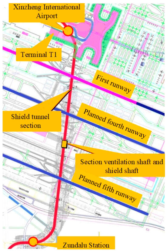
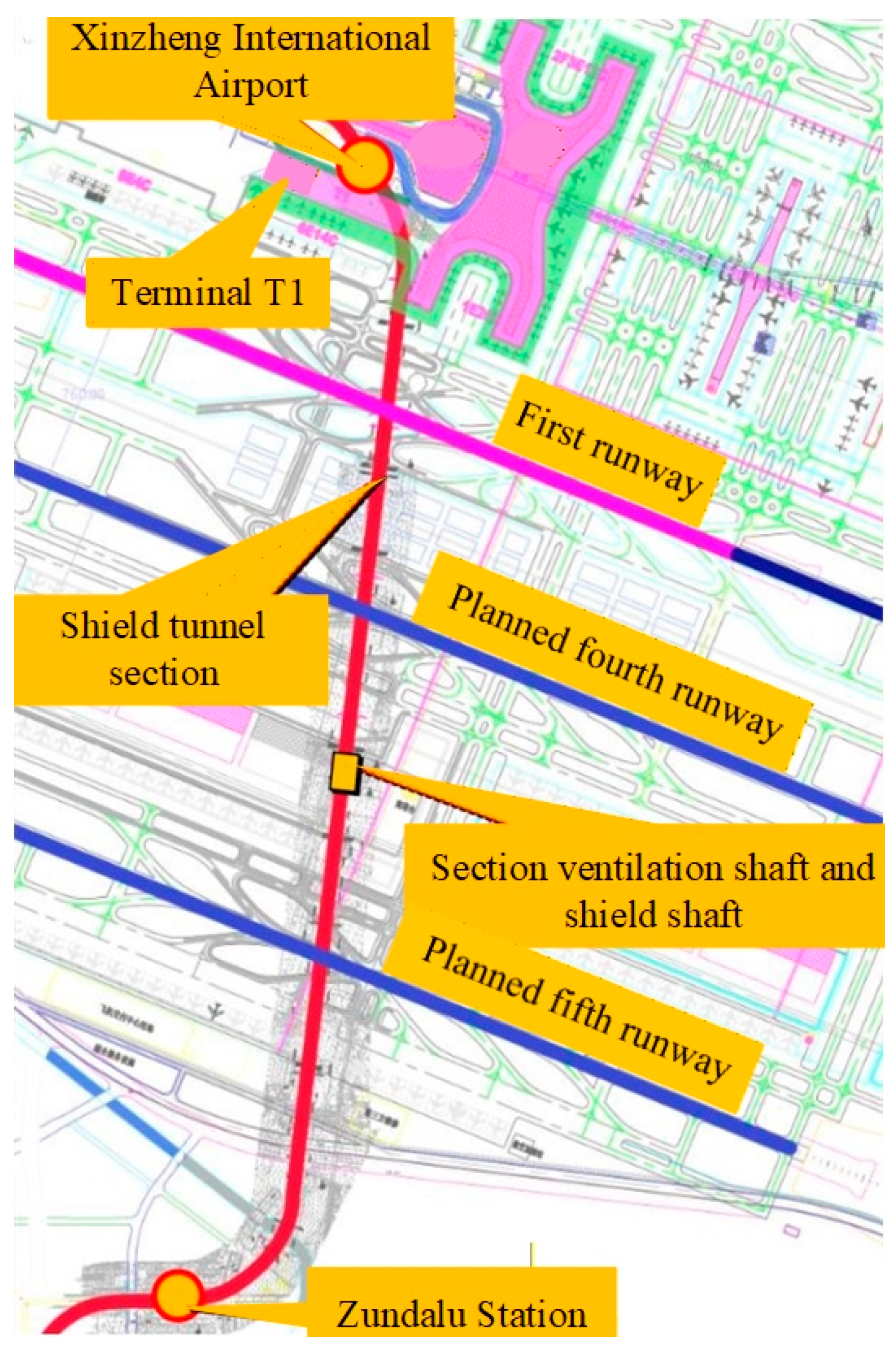
As shown in Figure 1, the Zhengzhou–Xuchang Intercity Railway is an important transport corridor connecting the Zhengzhou Airport Economy Zone and the core area of Xuchang. The tunnel passes beneath the elevated viaduct of the drop-off platform of Terminal T1 at Xinzheng International Airport, the Terminal T1 building, the first runway, and the planned fourth and fifth runways, and extends from farmlands south of the airport to Zunda Road Station. This study is conducted based on the shield tunnel section crossing beneath the elevated viaduct of the drop-off platform of Terminal T1 of Xinzheng International Airport.
Figure 1.
Alignment of the shield tunnel section of the Zhengzhou–Xuchang Intercity Railway crossing beneath Xinzheng International Airport.
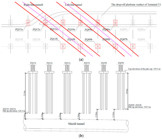
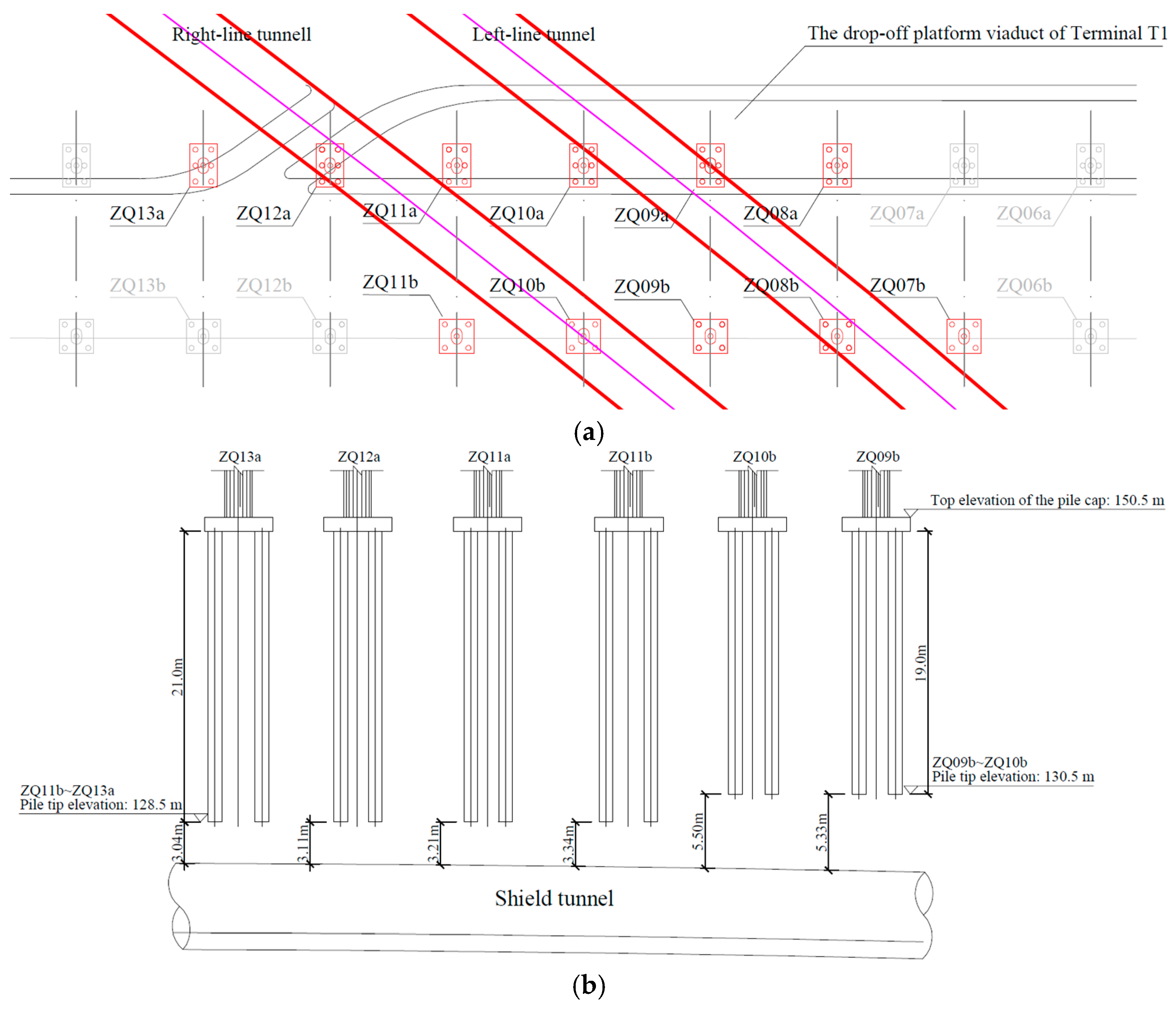
Figure 2 shows the relative position between the shield tunnel section and the pile foundations of the elevated viaduct at the Terminal T1 drop-off platform. During excavation, the shield machine crosses the pile-foundation zone obliquely, and the centre-to-centre spacing between the left-line and right-line tunnels is 15.8–16.9 m. The influences on pile foundations ZQ08a–ZQ13a and ZQ07b–ZQ11b are of particular concern during construction. The pile foundation structure consists of a pile cap and several piles. The pile cap transfers and distributes the superstructure load to individual piles, and the piles mainly transfer load to the surrounding soil through shaft friction. Type-a foundations comprise six piles, while Type-b foundations comprise four piles; each pile is a D500 mm × 125 mm friction-type high-strength prestressed precast concrete pipe pile. The transverse centre spacing between Type-a and Type-b foundations is 16.0 m and the longitudinal centre spacing is 12.0 m. The lengths of pile foundations ZQ13a–ZQ11a and ZQ11b are 21.0 m, and those of ZQ10a–ZQ08a and ZQ10b–ZQ07b are 19.0 m. The clear vertical distance between the pile tip and the tunnel crown ranges from 3.04 m to 5.50 m.
Figure 2.
Spatial relationship between the shield tunnels and pile foundations of the elevated viaduct at the drop-off platform viaduct of Terminal T1. (a) Plan view of tunnels and pile foundations. (b) Section view of tunnels and pile foundations.
2.2. Numerical Model and Validation Based on Engineering Project
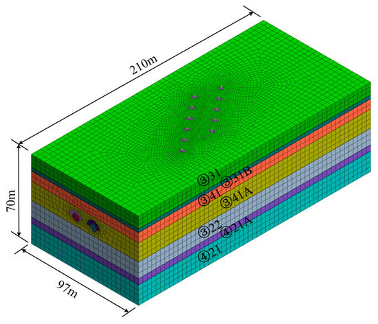
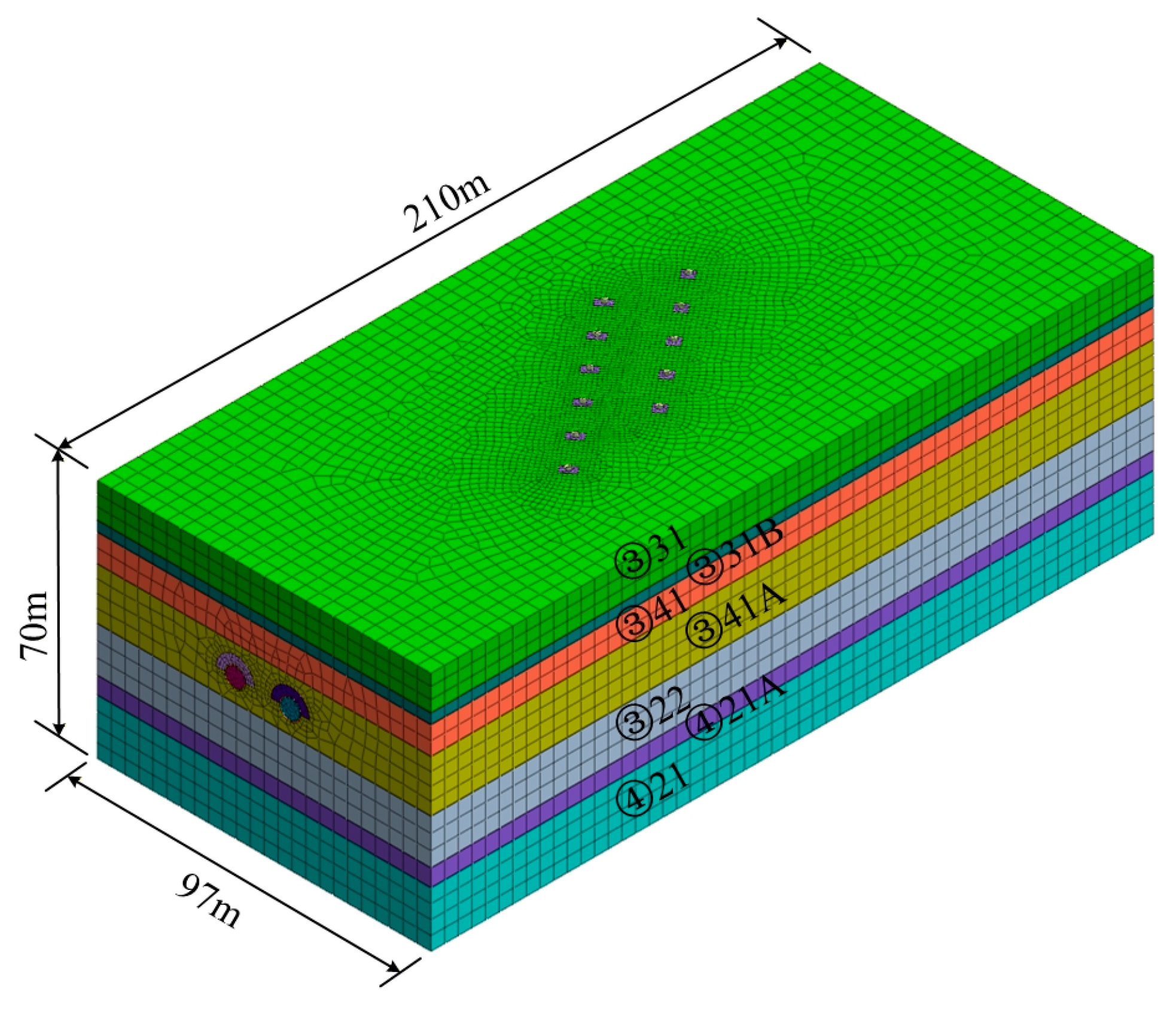
A three-dimensional numerical model for the twin shield tunnels crossing beneath the elevated viaduct of the Terminal T1 drop-off platform at Xinzheng International Airport was established using Midas GTS NX, as shown in Figure 3. Considering boundary effects of tunnel excavation and pile foundations, the model size was set to 97 m × 210 m × 70 m (X × Y × Z). As listed in Table 1 and Table 2, based on the engineering geological investigation report, the ground stratum mainly consists of layered clayey silt and silty clay, representing a typical cohesive soil stratum. The soil layers, pile cap, grouting layer and grouting improvement were modelled using three-dimensional solid elements [26,27,28]. To address the issue of excessive ground heave associated with the conventional Mohr–Coulomb constitutive model and to more accurately capture the nonlinear mechanical behaviour of soils, the modified Mohr–Coulomb constitutive model was adopted for the soil in this study [29]. The pile cap concrete grade is C30, and linear elastic models were used for the concrete and reinforcing steel. Piles were modelled using beam elements with a concrete grade of C80. The shield shell and tunnel lining segments were modelled using shell elements. The segment outer diameter is 6.2 m, inner diameter is 5.5 m, width is 1.5 m and thickness is 0.35 m. They were assembled using a staggered joint construction method [30].
Figure 3.
Numerical model for twin shield tunnels crossing beneath the pile foundations.
Table 1.
Mechanical parameters of soil layers.
Table 2.
Material parameters for the pile foundation and shield tunnels.
Table 3 compares the field monitoring data and numerical results of pile tip displacements after breakthrough of the twin tunnels. The monitored displacements of pile caps for both Type-a and Type-b foundations satisfy the monitoring control criteria for viaducts specified in the Technical Specification for Monitoring of Urban Rail Transit Engineering [31]. The absolute errors of the simulated vertical and horizontal displacements are both less than 10% [32], verifying the accuracy and reliability of the numerical model. Compared with the monitoring data, the simulated displacements were generally smaller. This is mainly attributed to the fact that vehicle loads and certain external loads were not fully considered in the numerical modelling, and that the pile–soil interaction was simplified by assuming a bonded interface without detailed contact behaviour.
Table 3.
Comparison between field monitoring data and numerical results of pile tip displacements.
3. Numerical Model for Parametric Study
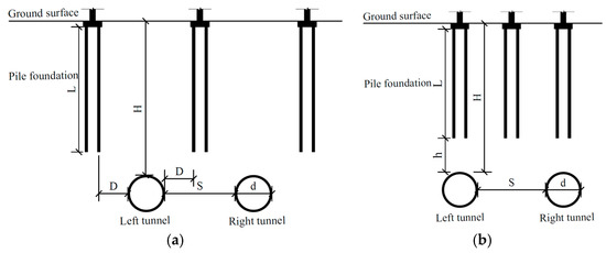
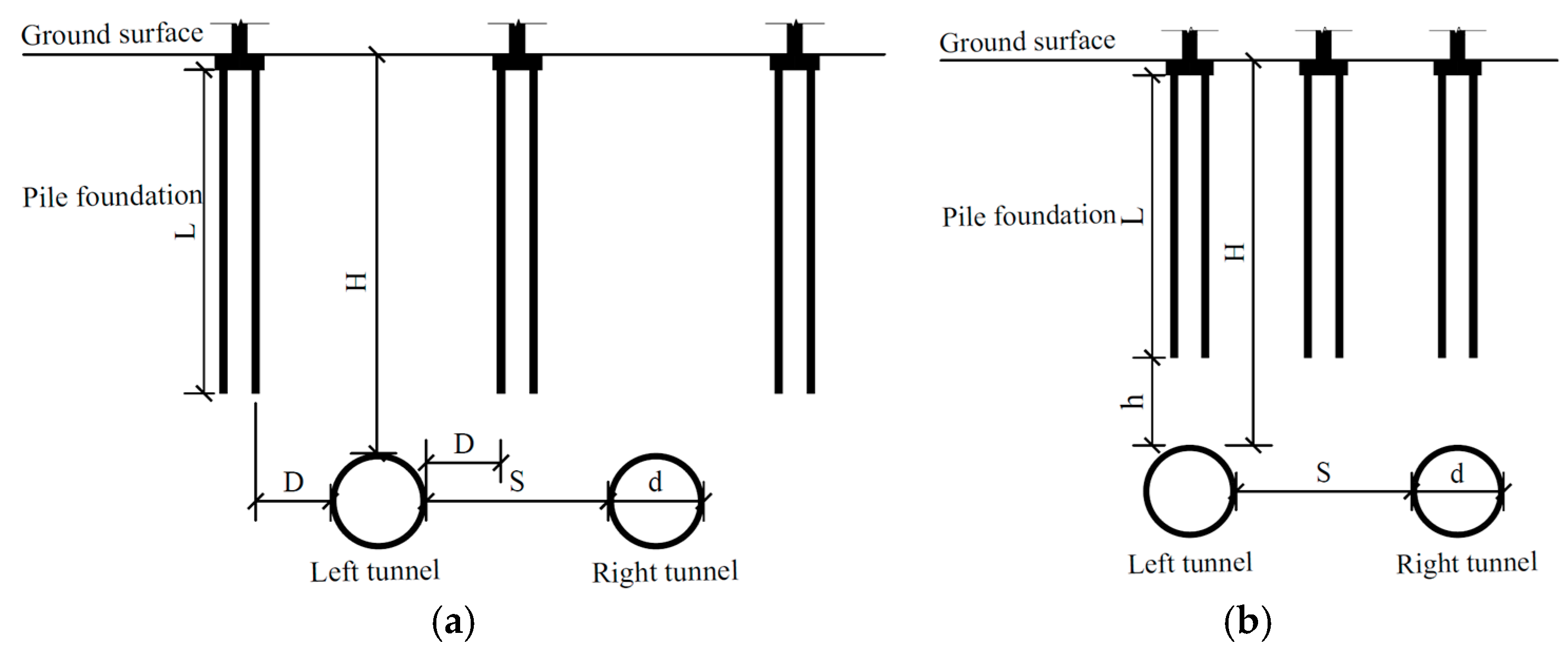
Based on the engineering numerical model shown in Figure 3, a new numerical model for parametric analysis was developed using the same modelling approach and parameter settings. As shown in Figure 4 and Table 4, two main tunnel crossing modes were considered: side-crossing of piles (hereafter “tunnel side-crossing”) and crossing beneath the pile tips (hereafter “tunnel under-crossing”). For each crossing mode, the influences of two key parameters, tunnel depth and pile foundation structure, on existing pile foundations were investigated.
Figure 4.
Crossing modes of twin shield tunnels relative to pile foundations. (a) Side-crossing of pile foundations. (b) Under-crossing beneath pile tips.
Table 4.
Numerical simulation cases for twin shield tunnelling.
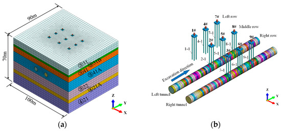
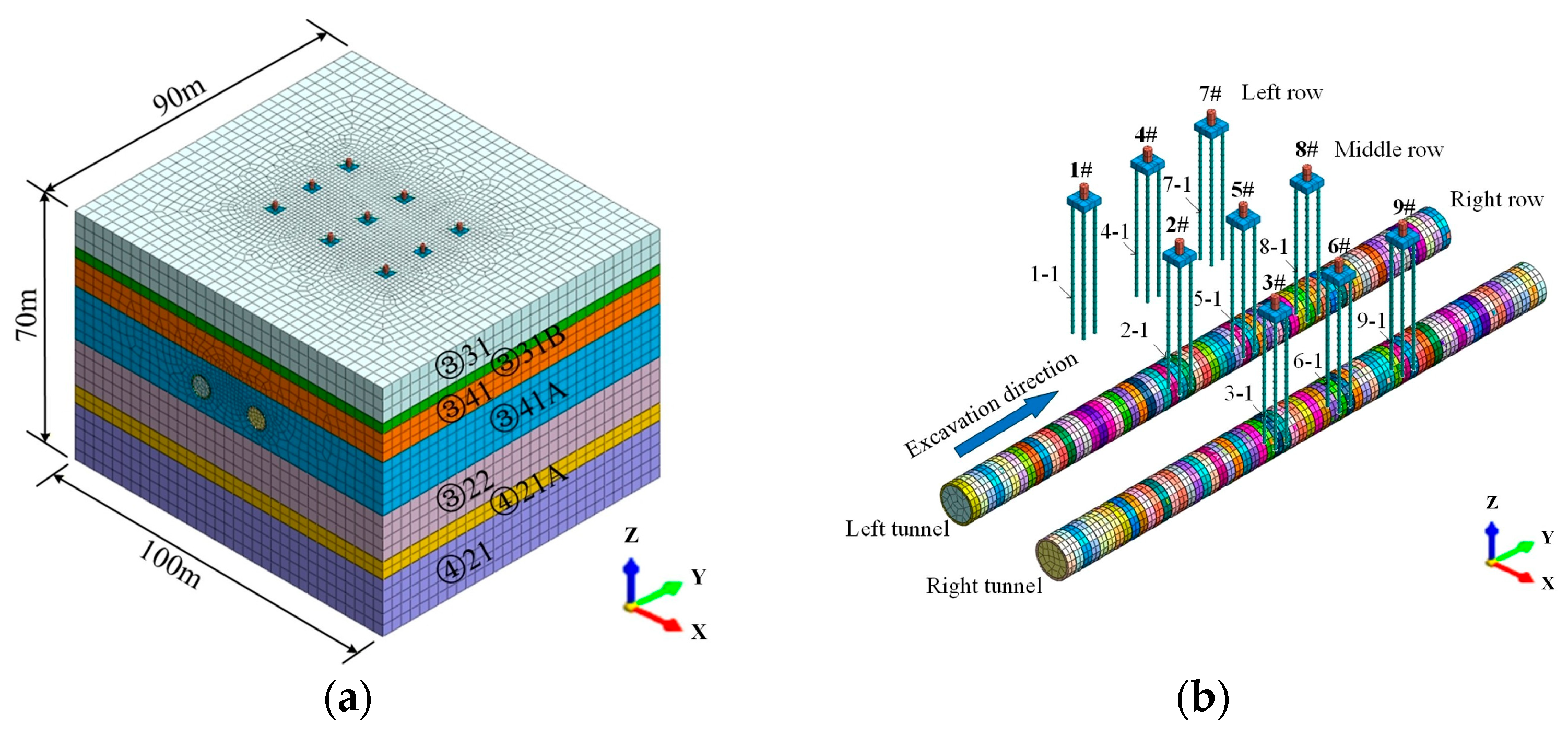
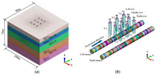
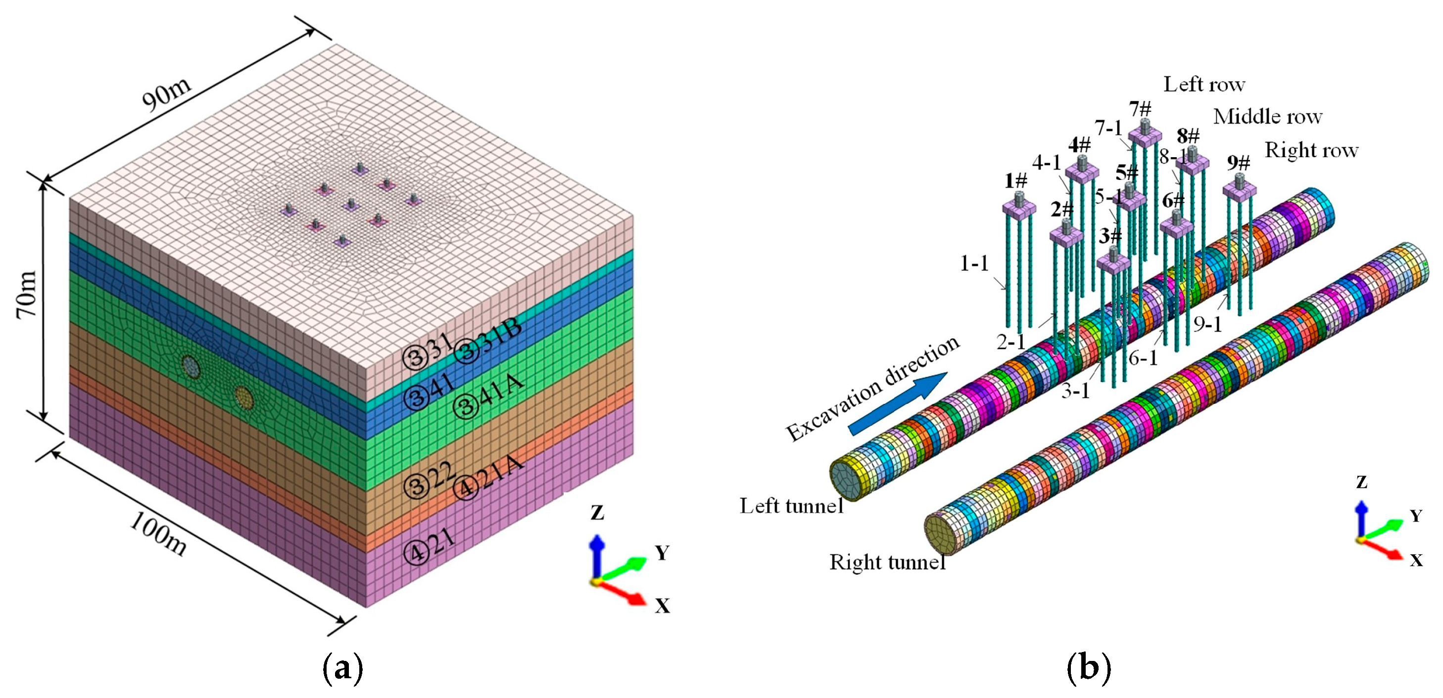
Figure 5 and Figure 6 present the numerical models for twin shield tunnel side-crossing and under-crossing of existing pile foundations, respectively. The model size was set to 100 m × 90 m × 70 m (X × Y × Z). The mechanical parameters of soil layers and the material parameters of the pile foundation and shield tunnels were adopted from Table 1 and Table 2. In both models, the pile foundation structure consists of four piles, and each pile foundation and its lower-left pile were numbered for subsequent analyses.
Figure 5.
Numerical model of twin shield tunnels side-crossing existing pile foundations. (a) Overall numerical model; (b) relative position between twin tunnels and pile foundations.
Figure 6.
Numerical model of twin shield tunnels under-crossing existing pile foundations. (a) Overall numerical model; (b) relative position between twin tunnels and pile foundations.
4. Results and Discussion
4.1. Parametric Analysis for Side-Crossing of Twin Shield Tunnels
4.1.1. Effect of Tunnel Depth
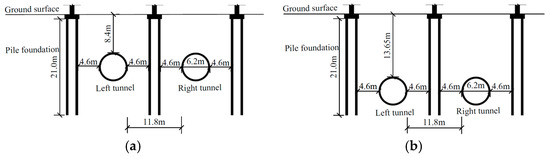
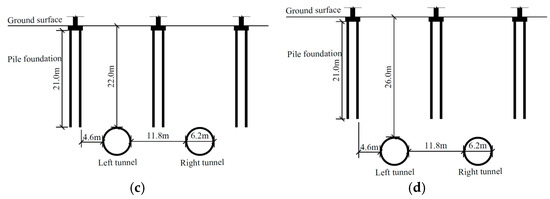
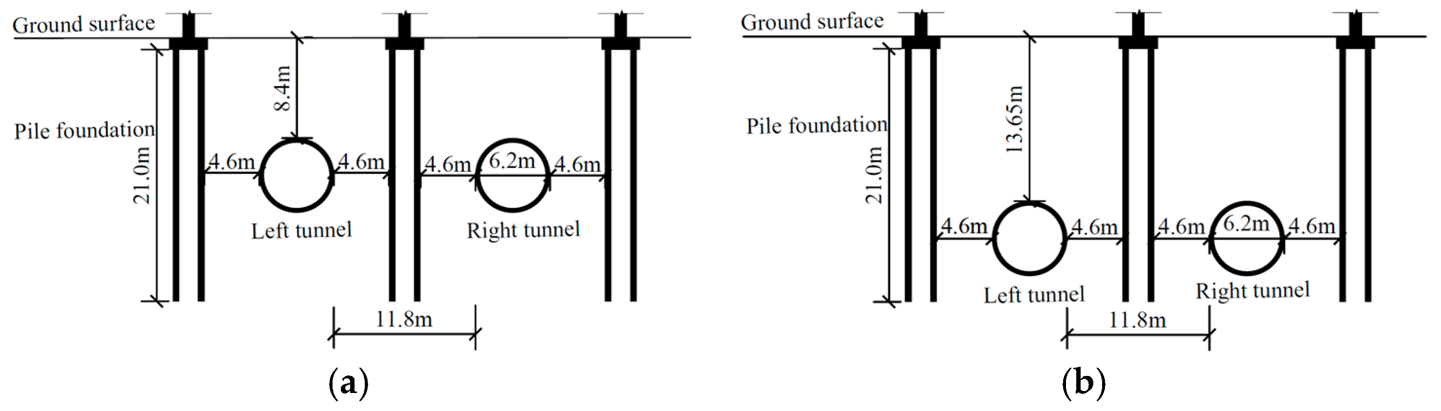
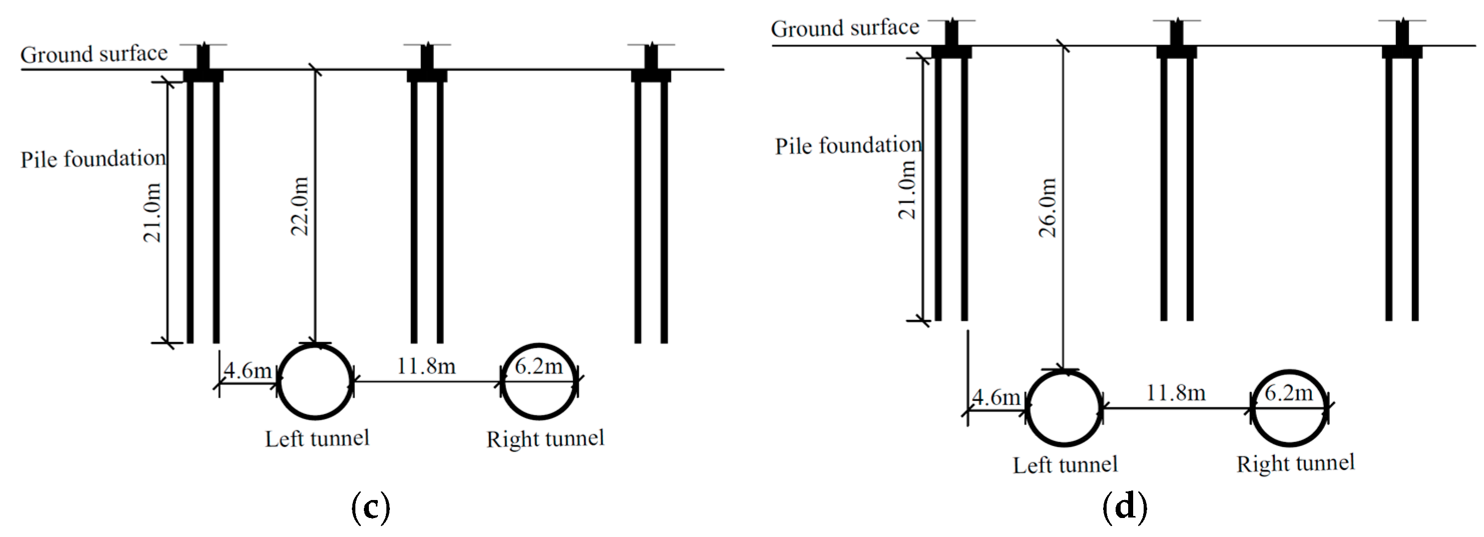
As shown in Table 4 and Figure 7, four cases (A1–A4) were designed to investigate the influence of tunnel depth on pile foundations during tunnel side-crossing, corresponding to tunnel depths of 8.4 m, 13.65 m, 22.0 m and 26.0 m, respectively. In Case A1, the tunnel centre is located at half the pile length; in Case A2, the tunnel centre is located at three-quarters of the pile length; in Case A3, the tunnel crown is located at the pile tip elevation; and Case A4 has the same tunnel depth as the actual project and is taken as the baseline case. The effects of tunnel depth on surface settlement, pile lateral displacement and pile axial force are analysed below.
Figure 7.
Sectional view of twin shield tunnel side-crossing construction at different burial depths. (a) Case A1 (H = 8.4 m); (b) Case A2 (H = 13.65 m); (c) Case A3 (H = 22.0 m); (d) Case A4 (H = 26.0 m).
- (1)
- Ground surface settlement
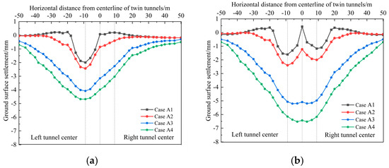
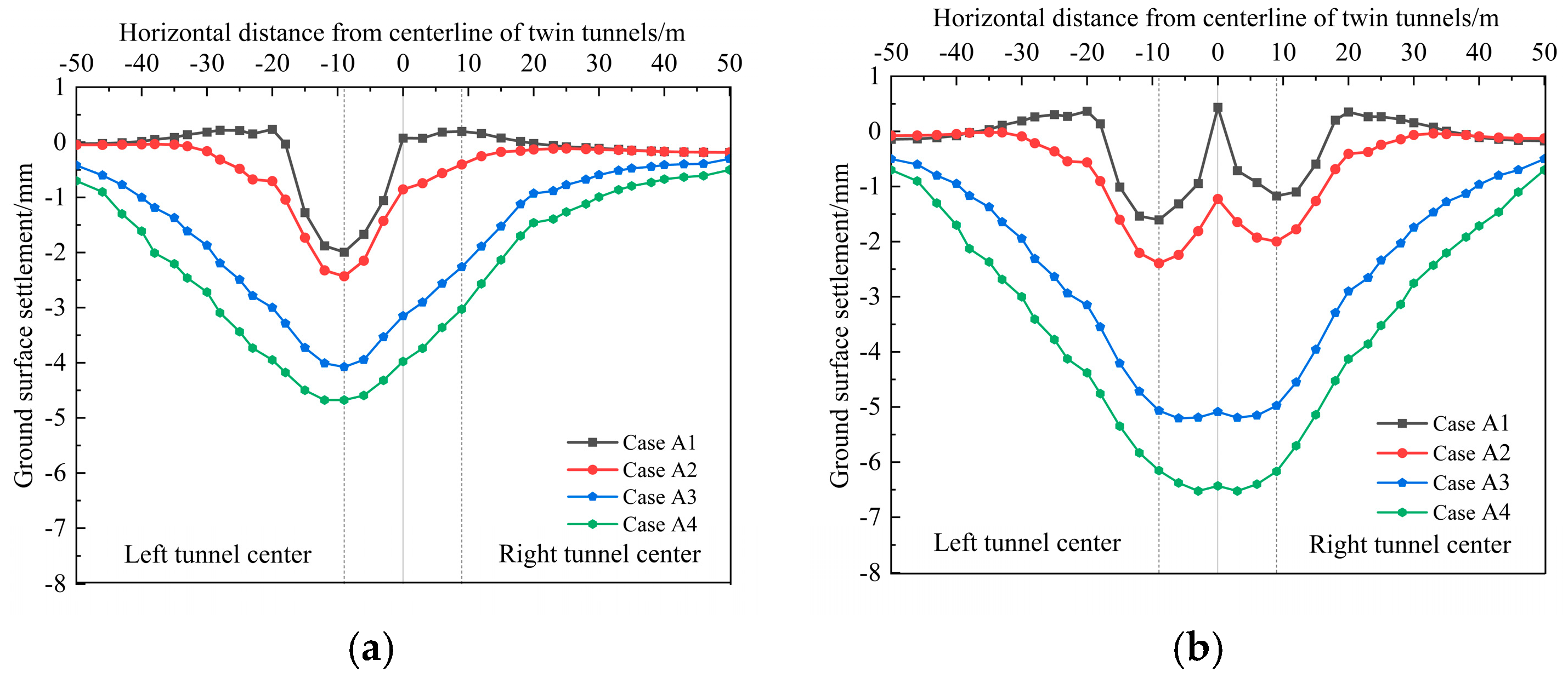
Figure 8 shows the ground surface settlement curve at Y = 45 m in the numerical model shown in Figure 5a. The following observations can be made: (i) The surface settlement increases with tunnel depth and increases markedly when the tunnel depth reaches the pile tip elevation or below. (ii) After breakthrough of the left-line tunnel, the excavation of deep soil layers induced unloading of the surrounding ground, disturbing the original stress equilibrium and leading to stress redistribution. As the cutterhead advanced, the surrounding soil gradually converged toward the tunnel, resulting in ground loss. The settlement profile is V-shaped, with the maximum settlement of 4.7 mm occurring directly above the left-line tunnel centre, which is consistent with the Peck formula for a single tunnel [33]. (iii) After breakthrough of twin tunnels, a new settlement trough forms above the right-line tunnel. Owing to the superposition of ground loss, the existing settlement above the left-line tunnel further increases and the profile evolves from a single-trough to a double-trough feature. When the tunnel depth is above the pile tip elevation, the surface settlement profile is W-shaped [34,35], and the maximum settlement remains directly above the left-line tunnel centre with a value of 2.4 mm. When the tunnel depth reaches or is shallower than the pile tip elevation, the profile becomes a weak W-shape, and the maximum settlement is located between the left-line tunnel centre and the centreline of the twin tunnels, reaching 6.5 mm. Under different burial depths, the extent of ground loss and the degree of stress release vary, leading to changes in the shape and peak position of the settlement trough. The settlement profile follows the distribution characteristics predicted by the superposition principle of Peck’s formula for twin tunnels [36,37].
Figure 8.
Influence of different tunnel depths on ground surface settlement during side-crossing construction of twin shield tunnels. (a) Surface settlement after breakthrough of the left-line tunnel. (b) Surface settlement after breakthrough of the twin tunnels.
- (2)
- Pile lateral displacement
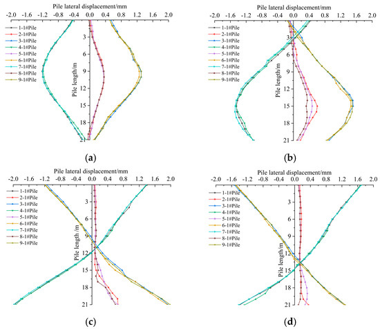
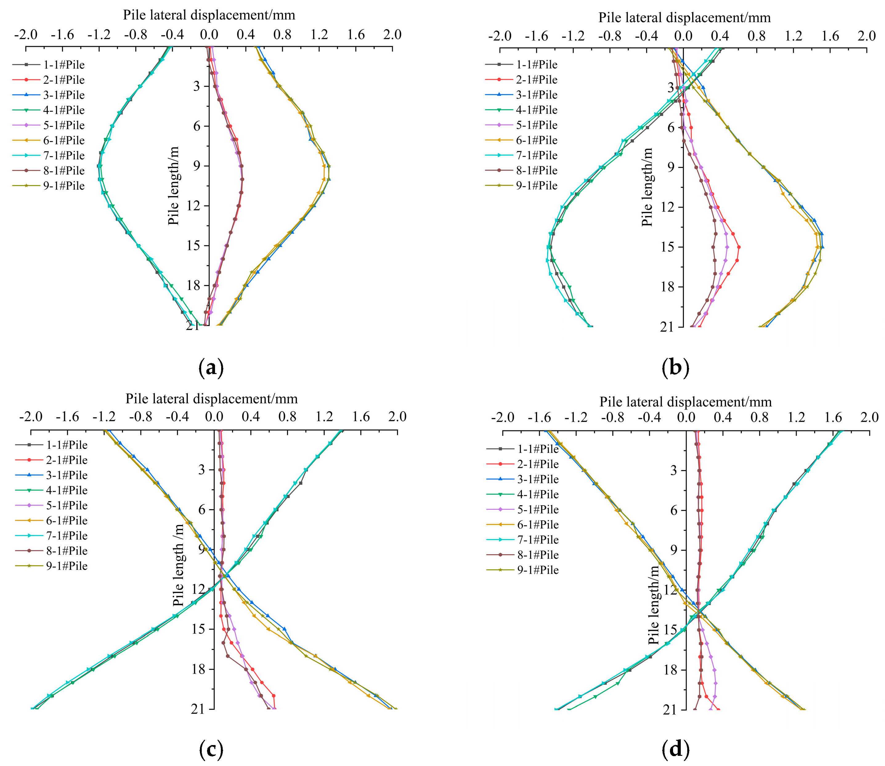
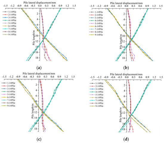
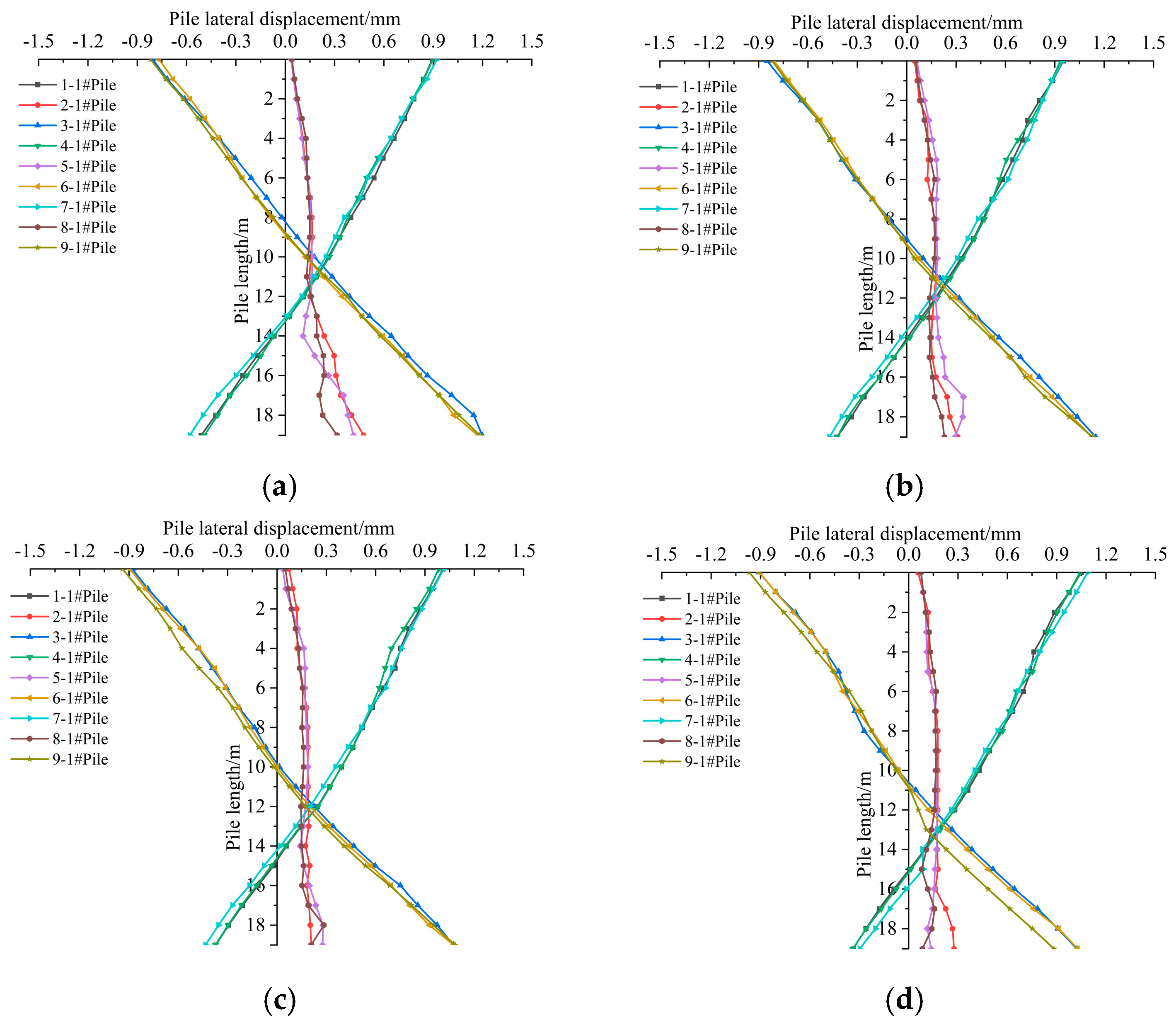
Figure 9 shows the distribution of lateral displacement of piles along the pile length under different tunnel depths after breakthrough of the twin tunnels. The lower-left pile of each pile foundation structure in the model shown in Figure 5b was selected for analysis. The pile lateral displacement is defined as positive in the X-axis direction. The results indicate the following: (i) The shapes of lateral displacement profiles for piles in the left row (1-1#, 4-1#, 7-1#), middle row (2-1#, 5-1#, 8-1#) and right row (3-1#, 6-1#, 9-1#) are generally similar. Because the left-line tunnel was excavated before the right-line tunnel, the stress release and redistribution of the soil between the two tunnels are asymmetric, leading to an overall offset of middle-row piles toward the right-line tunnel. (ii) When the tunnel depth is above the pile tip elevation, excavation and segment deformation induce a squeezing effect on lateral soils, forcing the left-row and right-row piles to move away from the tunnels; consequently, the pile lateral displacement profiles shows a spindle shape [38,39]. The maximum absolute lateral displacement occurs in Pile 7-1# in the left row, with a value of 1.5 mm located near the tunnel centre elevation. (iii) When the tunnel depth reaches or is shallower than the pile tip elevation, the excavation of deep soil causes settlement of the overlying ground. As the soil converges toward the tunnel, the pile head moves toward the tunnel, while the squeezing effect of the deep soil induces a tendency for the pile top to move away from the tunnel [40]. As a result, the lateral displacement profiles of the left-row and right-row piles become X-shaped. The maximum displacement of the pile top occurs in Pile 7-1# in the left row, reaching 1.7 mm.
Figure 9.
Influence of different tunnel depths on pile lateral displacement during side-crossing construction of twin shield tunnels. (a) Case A1 (H = 8.4 m): pile lateral displacement; (b) Case A2 (H = 13.65 m): pile lateral displacement; (c) Case A3 (H = 22.0 m): pile lateral displacement; (d) Case A4 (H = 26.0 m): pile lateral displacement.
- (3)
- Pile axial force
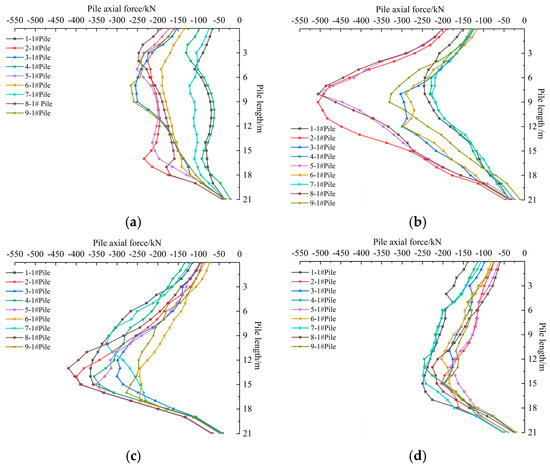
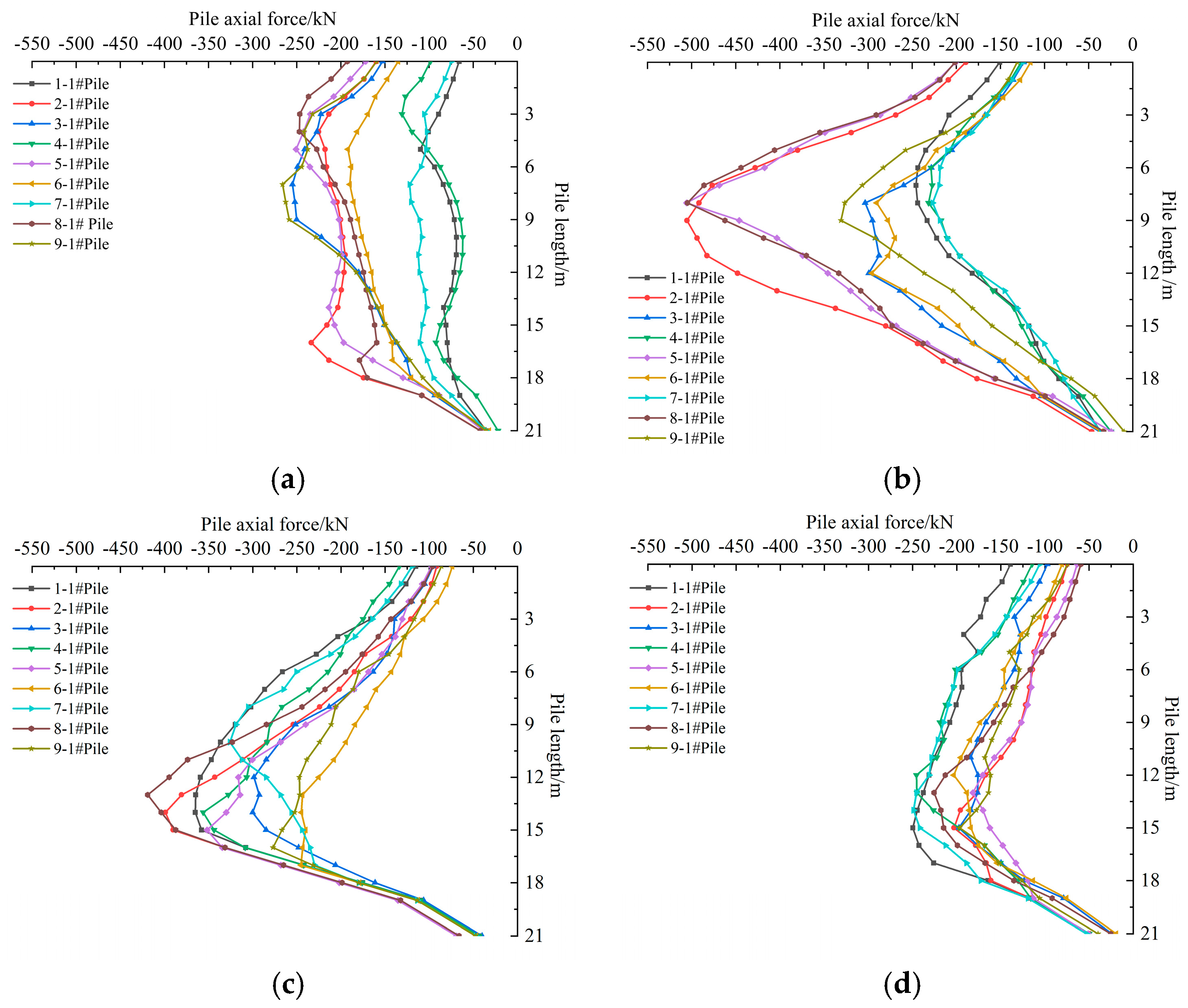
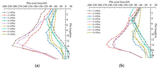
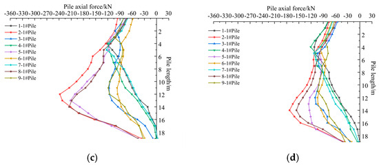
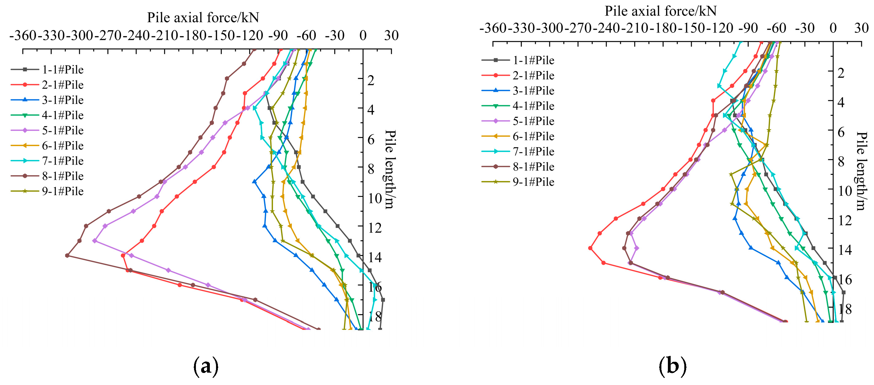
Figure 10 shows the distribution of pile axial force along the pile length for different tunnel depths after breakthrough of the twin tunnels; the pile axial force is positive when tensile. The results show that (i) the axial force variation patterns of the piles are generally consistent. When the surrounding soil settles due to tunnel construction and the soil settlement exceeds that of the pile, negative skin friction gradually develops along the pile shaft. This negative skin friction generates a downdrag effect, transferring load downward along the pile shaft and resulting in redistribution of axial force within the pile. As the tunnel burial depth varies, the extent of soil stress release changes accordingly, leading to variations in the development zone of negative skin friction and the location of the neutral plane. Consequently, the pile axial force first increases and then decreases, and the location of the maximum axial force shifts downward with increasing tunnel burial depth [41,42]. (ii) When the tunnel depth is above the pile tip elevation, the maximum axial force of a single pile increases with tunnel depth. Taking Pile 8-1# in the middle row as an example, the maximum axial force increases from 248.1 kN to 505.8 kN (an increase of 103.9%), and its position shifts from 4.0 m to 8.0 m. (iii) When the tunnel depth reaches the pile tip elevation or below, deeper excavation leads to more pronounced soil settlement, and the negative skin friction on the pile shaft increases significantly and its influence zone moves downward; consequently, the maximum axial force decreases with tunnel depth. For Pile 8-1#, the maximum axial force decreases from 419.1 kN to 225.6 kN (a reduction of 46.2%), and its position shifts from 13.0 m to 15.0 m.
Figure 10.
Influence of different tunnel depths on pile axial force during side-crossing construction of twin shield tunnels. (a) Case A1 (H = 8.4 m): pile axial force; (b) Case A2 (H = 13.65 m): pile axial force; (c) Case A3 (H = 22.0 m): pile axial force; (d) Case A4 (H = 26.0 m): pile axial force.
4.1.2. Effect of Pile Foundation Structure
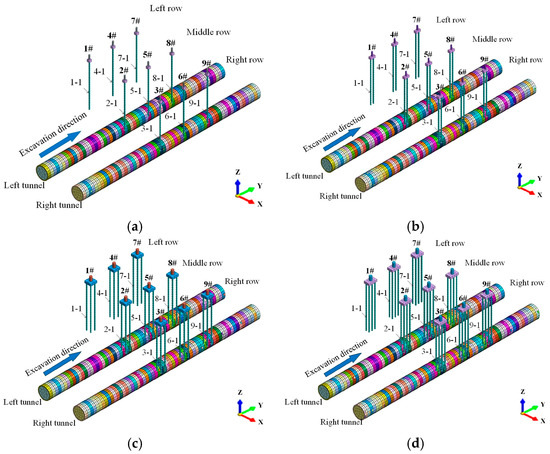
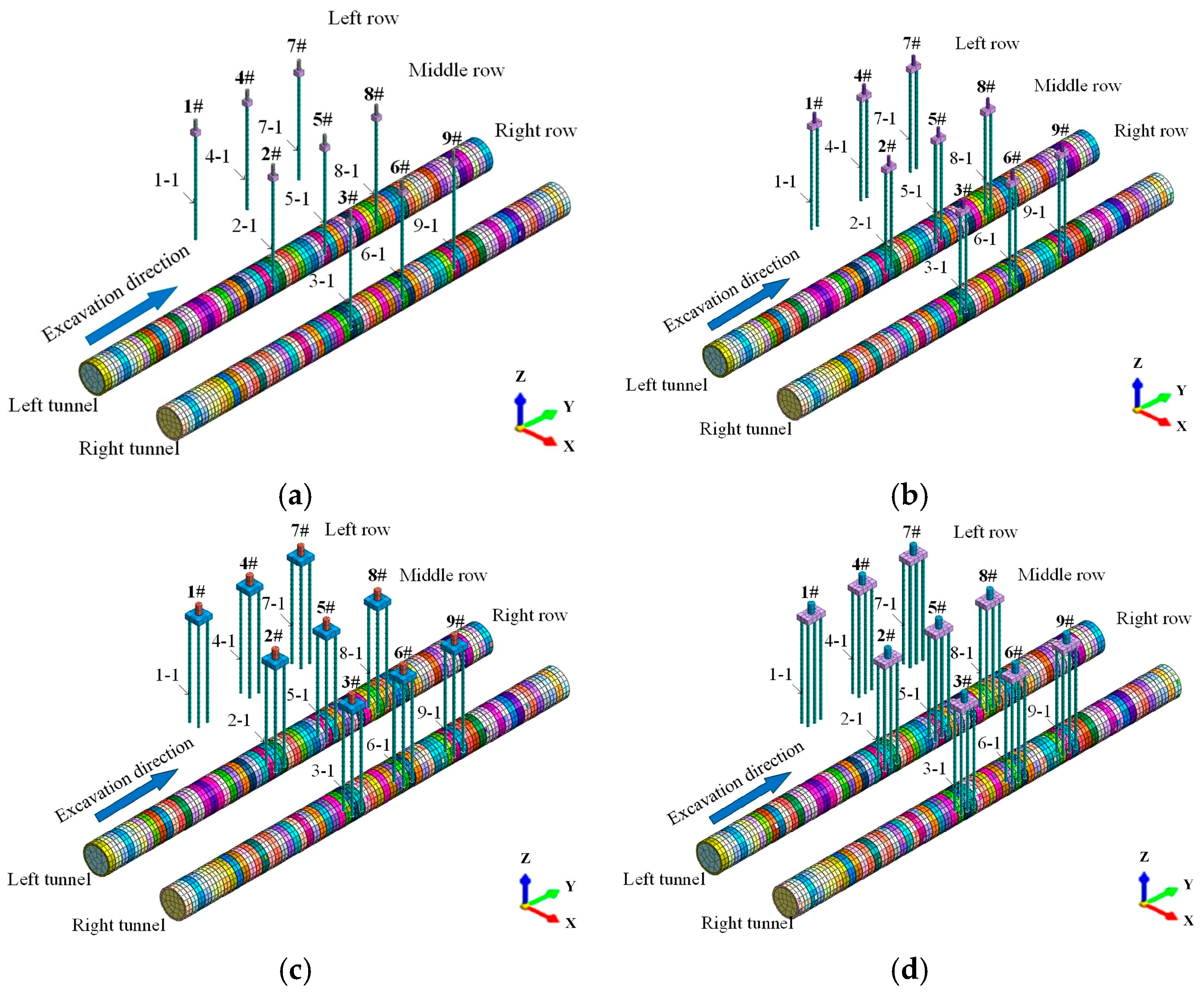
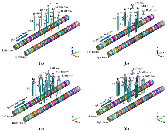
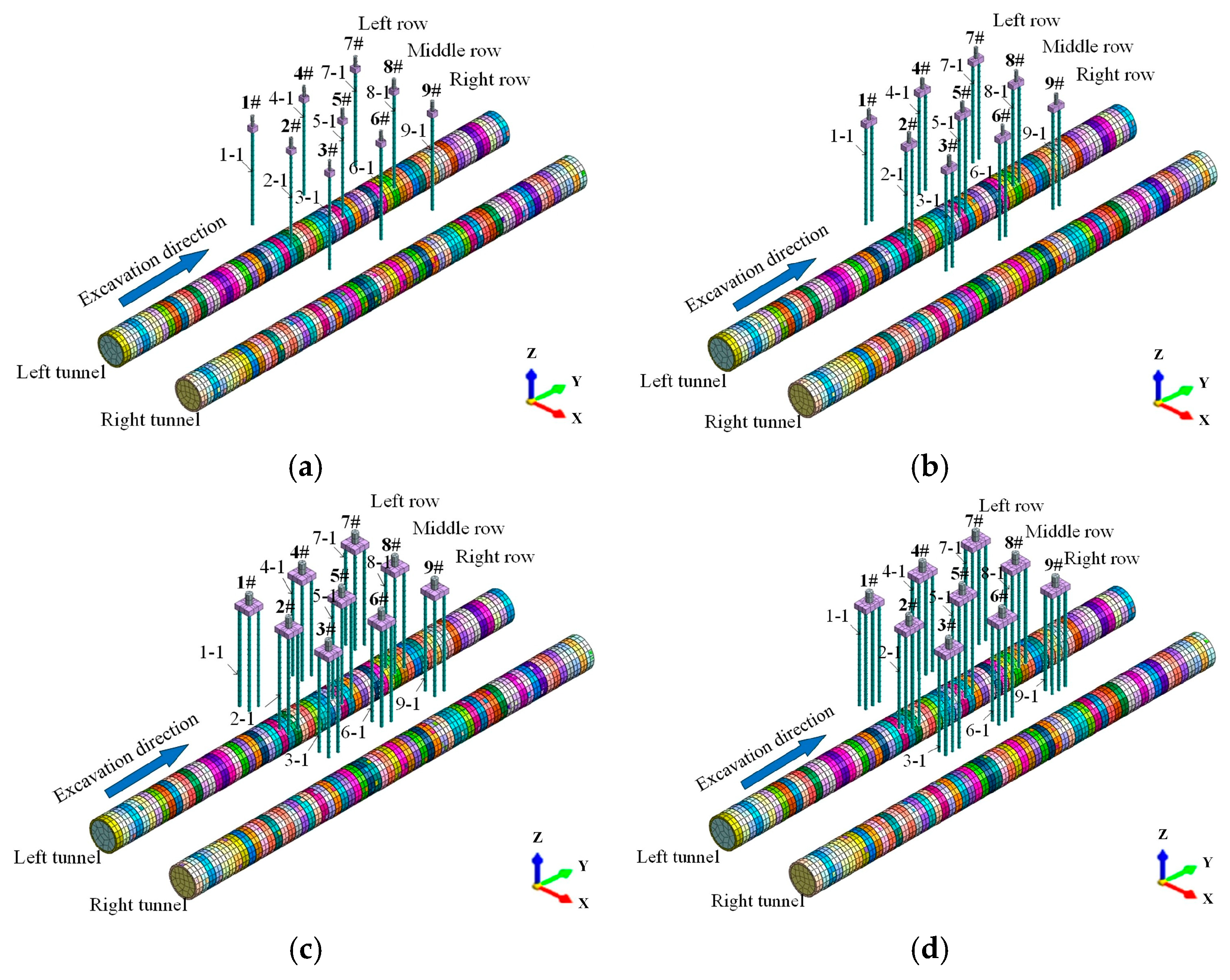
As listed in Table 4 and shown in Figure 11, four cases (B1–B4) were designed to investigate the influence of pile foundation structure during tunnel side-crossing, corresponding to a single pile, two piles, four piles and six piles, respectively. The four-pile configuration in Case B3 is the same as that in the actual project; Case B3 is identical to Case A4 in Table 4 and is also taken as the baseline case.
Figure 11.
Numerical model for different pile foundation structures during tunnel side-crossing. (a) Case B1 (single-pile); (b) Case B2 (two-pile); (c) Case A3 Case B3 (four-pile); (d) Case B4 (six-pile).
- (1)
- Ground surface settlement
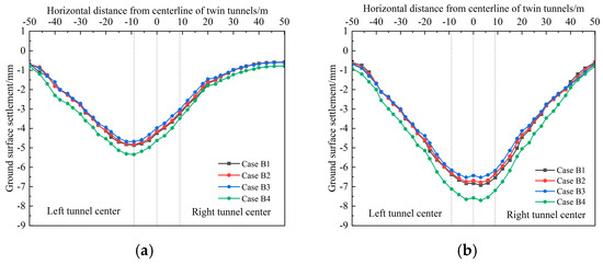
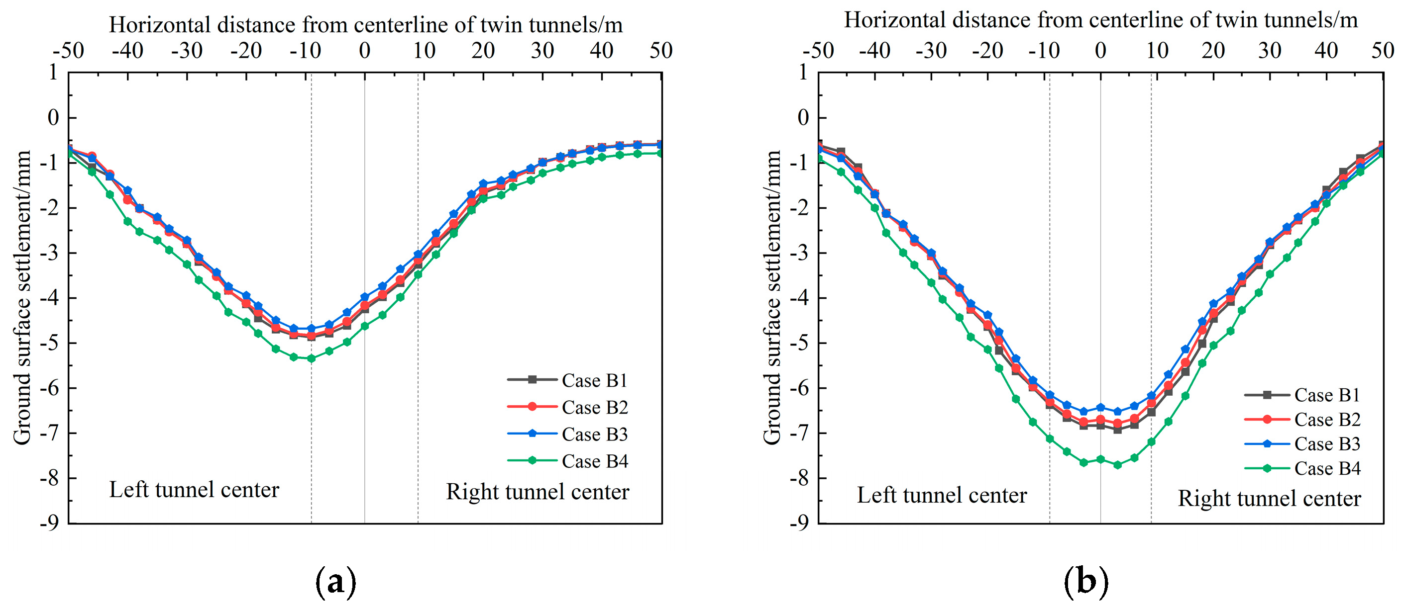
Figure 12 shows the ground surface settlement curve at Y = 45 m in the numerical model shown in Figure 5a. The results indicate that: (i) During tunnel side-crossing, the influence of pile foundation structure on surface settlement is insignificant. (ii) After breakthrough of the left-line tunnel, ground settlement caused by excavation of deep soil layers resulted in soil convergence toward the tunnel axis; the settlement profile is V-shaped with a maximum settlement of 5.3 mm directly above the left-line tunnel centre, consistent with the Peck formula for a single tunnel. (iii) After breakthrough of twin tunnels, the settlement profile becomes a weak W shape with a maximum settlement of 7.7 mm located between the right-line tunnel centre and the centreline of the twin tunnels, consistent with the Peck-based superposition for twin tunnels.
Figure 12.
Influence of different pile foundation structures on ground surface settlement during side-crossing construction of twin shield tunnels. (a) Surface settlement after breakthrough of the left-line tunnel. (b) Surface settlement after breakthrough of the twin tunnels.
- (2)
- Pile lateral displacement
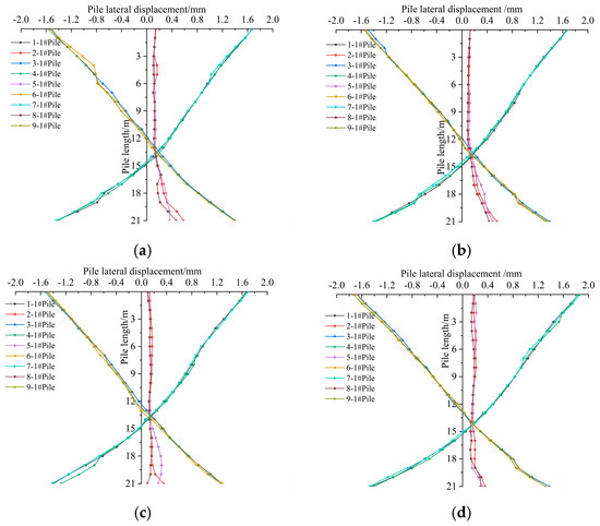
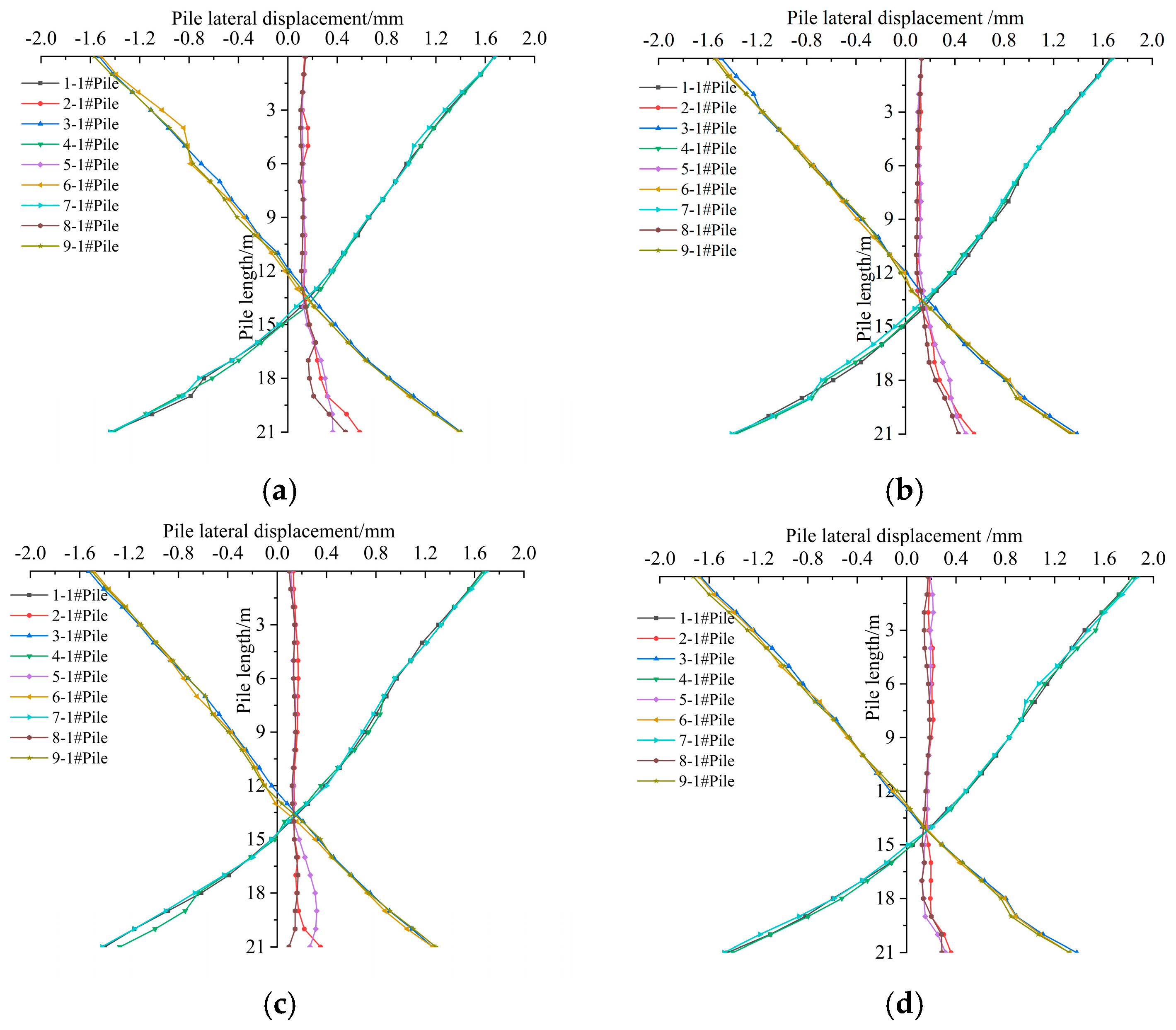
Figure 13 shows the distribution of pile lateral displacement along the pile length for different pile foundation structures after breakthrough of the twin tunnels. The lower-left pile of each pile foundation in the model shown in Figure 11 was selected for analysis. The results show that: (i) The shapes of lateral displacement profiles for piles in the same row are generally consistent; the left-row and right-row piles exhibit X-shaped profiles, while the middle-row piles show an overall offset toward the right-line tunnel. (ii) The effect of pile foundation structure on pile lateral displacement is not obvious, and the maximum displacement of the pile top occurs in Pile 7-1# in the left row, reaching 1.9 mm.
Figure 13.
Influence of different pile foundation structures on pile lateral displacement during side-crossing construction of twin shield tunnels. (a) Case B1 (single-pile): pile lateral displacement; (b) Case B2 (two-pile): pile lateral displacement; (c) Case B3 (four-pile): pile lateral displacement; (d) Case B4 (six-pile): pile lateral displacement.
- (3)
- Pile axial force
Figure 14 shows the distribution of pile axial force along the pile length for different pile foundation structures after breakthrough of the twin tunnels. The results indicate that: (i) The axial-force distribution shapes for piles in the same row are generally consistent; the axial force increases first and then decreases along the pile length, and the maximum axial force is located near three-quarters of the pile length. (ii) As the number of piles increases, the maximum axial force of a single pile gradually decreases. Taking pile 5-1# in the middle-row as an example, the maximum axial force decreases from 320.1 kN to 197.4 kN (about 38.3% reduction). This suggests that increasing the number of piles can effectively share the negative skin friction induced by surrounding soil settlement, reduce the maximum axial force of individual piles, and improve the overall safety of the pile foundation [43].
Figure 14.
Influence of different pile foundation structures on pile axial force during side-crossing construction of twin shield tunnels. (a) Case B1 (single-pile): pile axial force; (b) Case B2 (two-pile): pile axial force; (c) Case B3 (four-pile): pile axial force; (d) Case B4 (six-pile): pile axial force.
4.2. Parametric Analysis for Under-Crossing of Twin Shield Tunnels
4.2.1. Effect of Tunnel Depth
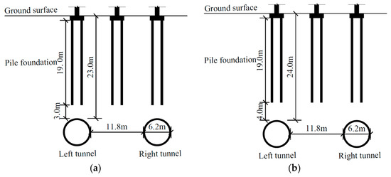
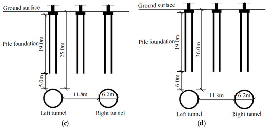
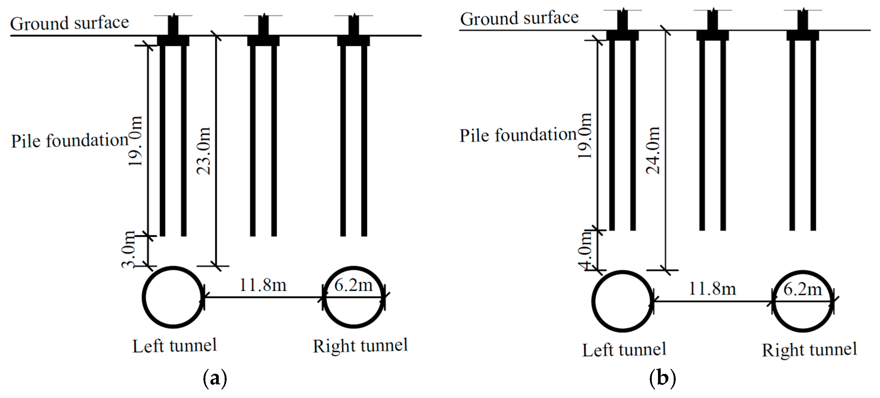
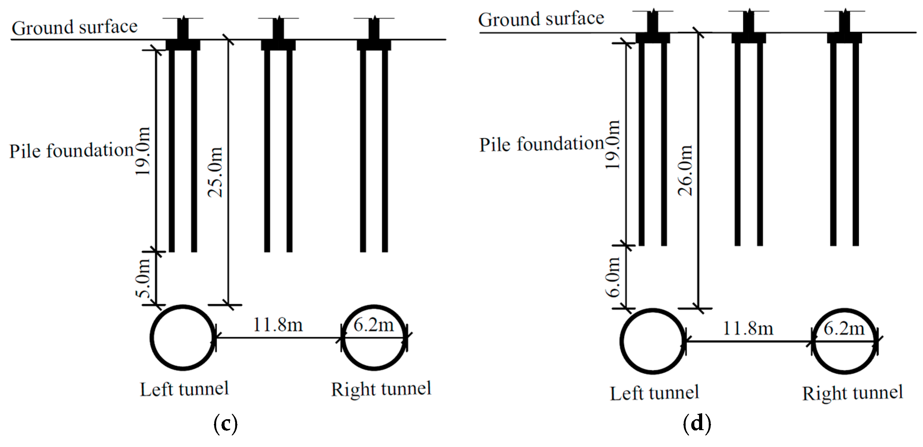
As listed in Table 4 and shown in Figure 15, four cases (C1–C4) were designed to investigate the influence of tunnel depth on pile foundations during tunnel under-crossing, corresponding to tunnel depths of 23.0 m, 24.0 m, 25.0 m and 26.0 m, respectively. The corresponding tunnel–pile clear distances are 3.0 m, 4.0 m, 5.0 m and 6.0 m. Case C4 has the same tunnel depth as the actual project and is taken as the baseline case.
Figure 15.
Sectional view of twin shield tunnel under-crossing construction at different burial depths. (a) Case C1 (H = 23.0 m); (b) Case C2 (H = 24.0 m); (c) Case C3 (H = 25.0 m); (d) Case C4 (H = 26.0 m).
- (1)
- Ground surface settlement
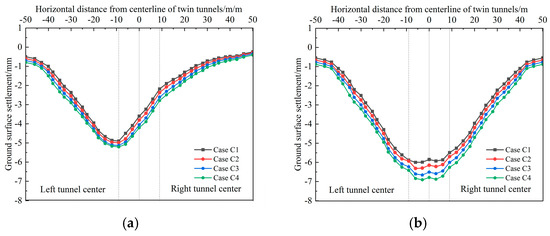
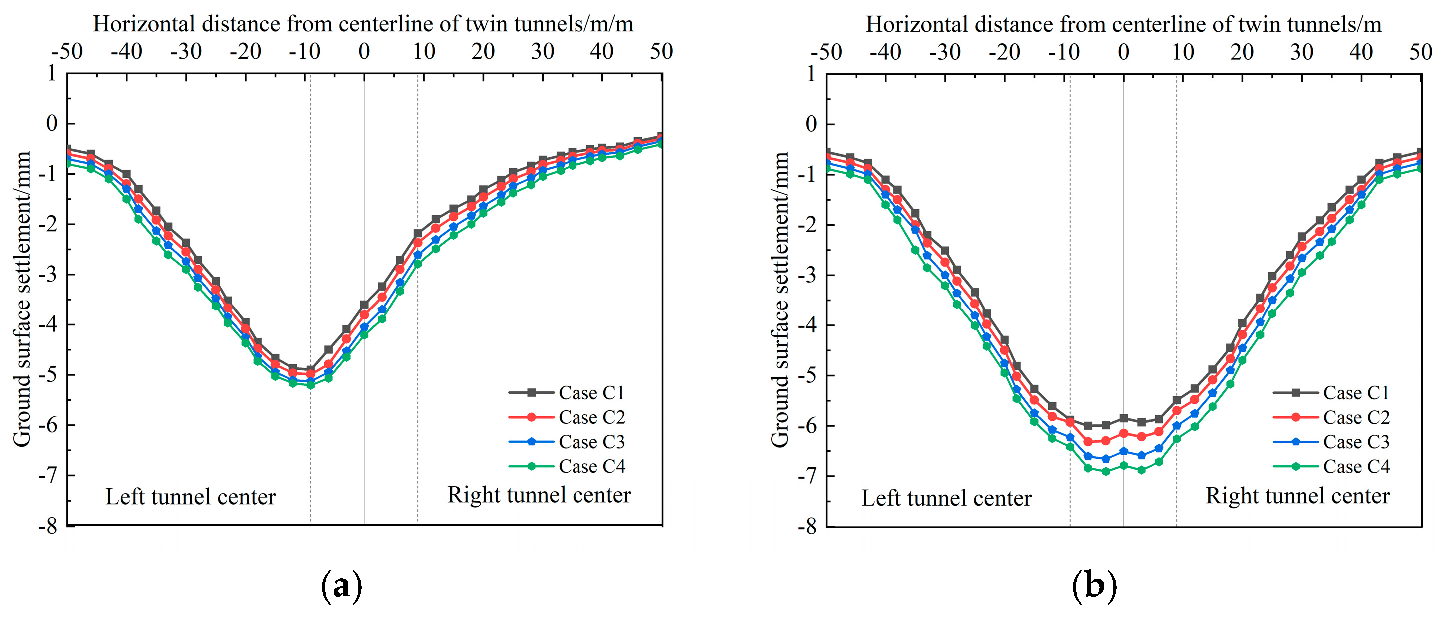
Figure 16 shows the ground surface settlement curve at Y = 45 m in the numerical model shown in Figure 6a. The results indicate that: (i) The surface settlement increases slightly with tunnel depth, suggesting that tunnel depth has a limited influence on surface settlement. (ii) After breakthrough of the left-line tunnel, the settlement profile is V-shaped with a maximum settlement of 5.2 mm directly above the left-line tunnel centre, consistent with the Peck formula for a single tunnel. (iii) After breakthrough of twin tunnels, the settlement profile becomes U-shaped, with a maximum settlement of 6.9 mm located between the left-line tunnel centre and the centreline of the twin tunnels. The settlement curve is consistent with the characteristics of the Peck-based superposition for twin tunnels.
Figure 16.
Influence of different tunnel depths on ground surface settlement during under-crossing construction of twin shield tunnels. (a) Surface settlement after breakthrough of the left-line tunnel; (b) Surface settlement after breakthrough of the twin tunnels.
- (2)
- Pile lateral displacement
Figure 17 shows the distribution of pile lateral displacement along the pile length for different tunnel depths after breakthrough of the twin tunnels. The lower-left pile of each pile foundation in the model shown in Figure 6b was selected for analysis. The results indicate that: (i) The shapes of lateral displacement profiles for piles in the same row are generally consistent. The left-row and right-row piles exhibit X-shaped profiles, while the middle-row piles show an overall offset toward the right-line tunnel. (ii) With increasing tunnel depth, the absolute pile-top lateral displacement increases slightly. The maximum displacement of the pile top occurs in Pile 4-1# in the left row, reaching 1.1 mm.
Figure 17.
Influence of different tunnel depths on pile lateral displacement during under-crossing construction of twin shield tunnels. (a) Case C1 (H = 23.0 m): pile lateral displacement; (b) Case C2 (H = 24.0 m): pile lateral displacement; (c) Case C3 (H = 25.0 m): pile lateral displacement; (d) Case C4 (H = 26.0 m): pile lateral displacement.
- (3)
- Pile axial force
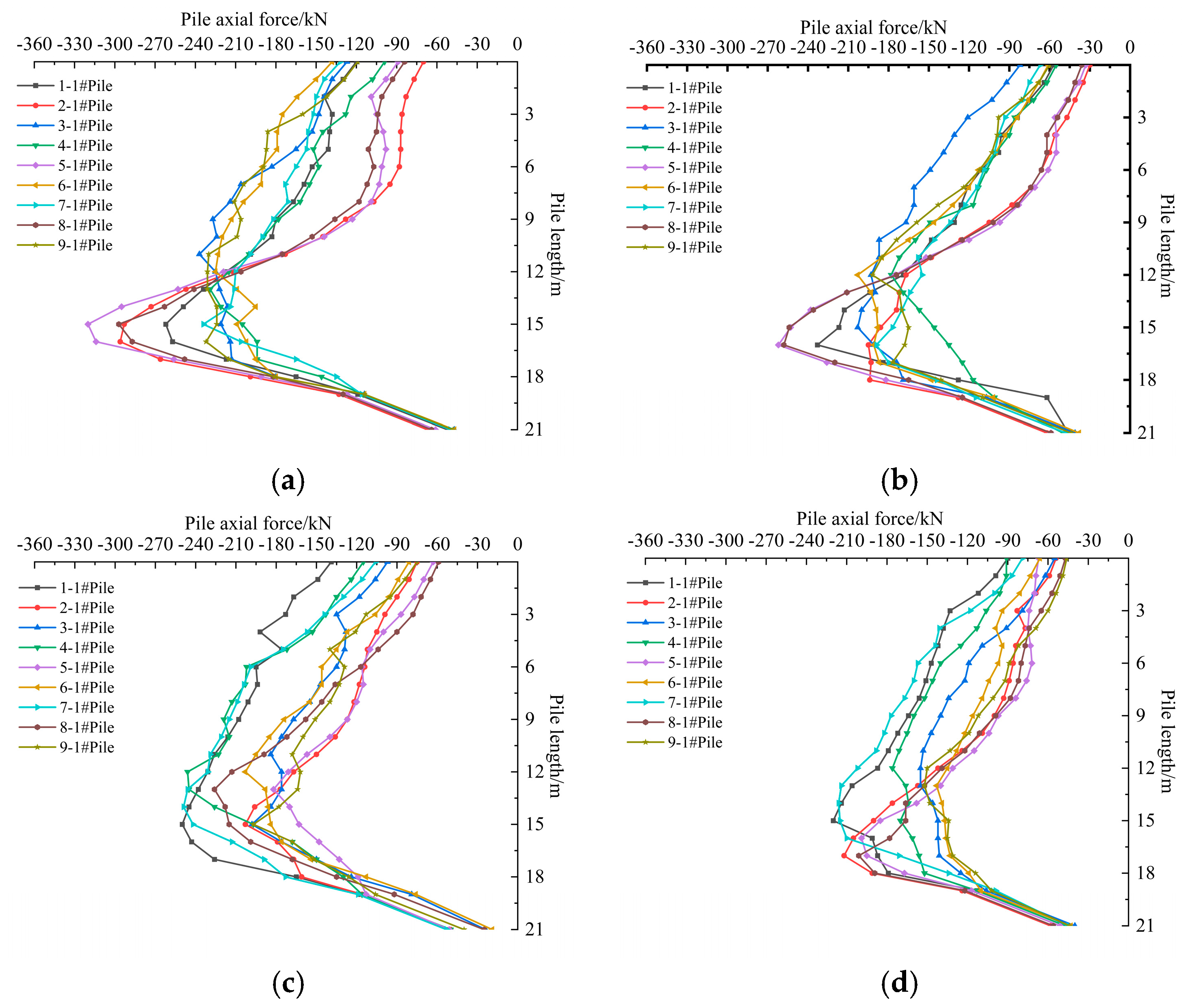
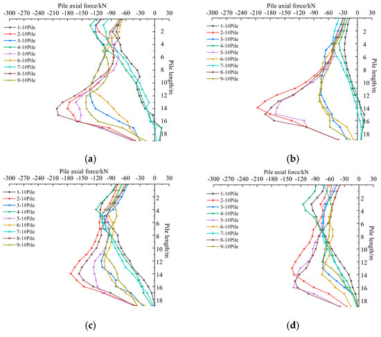
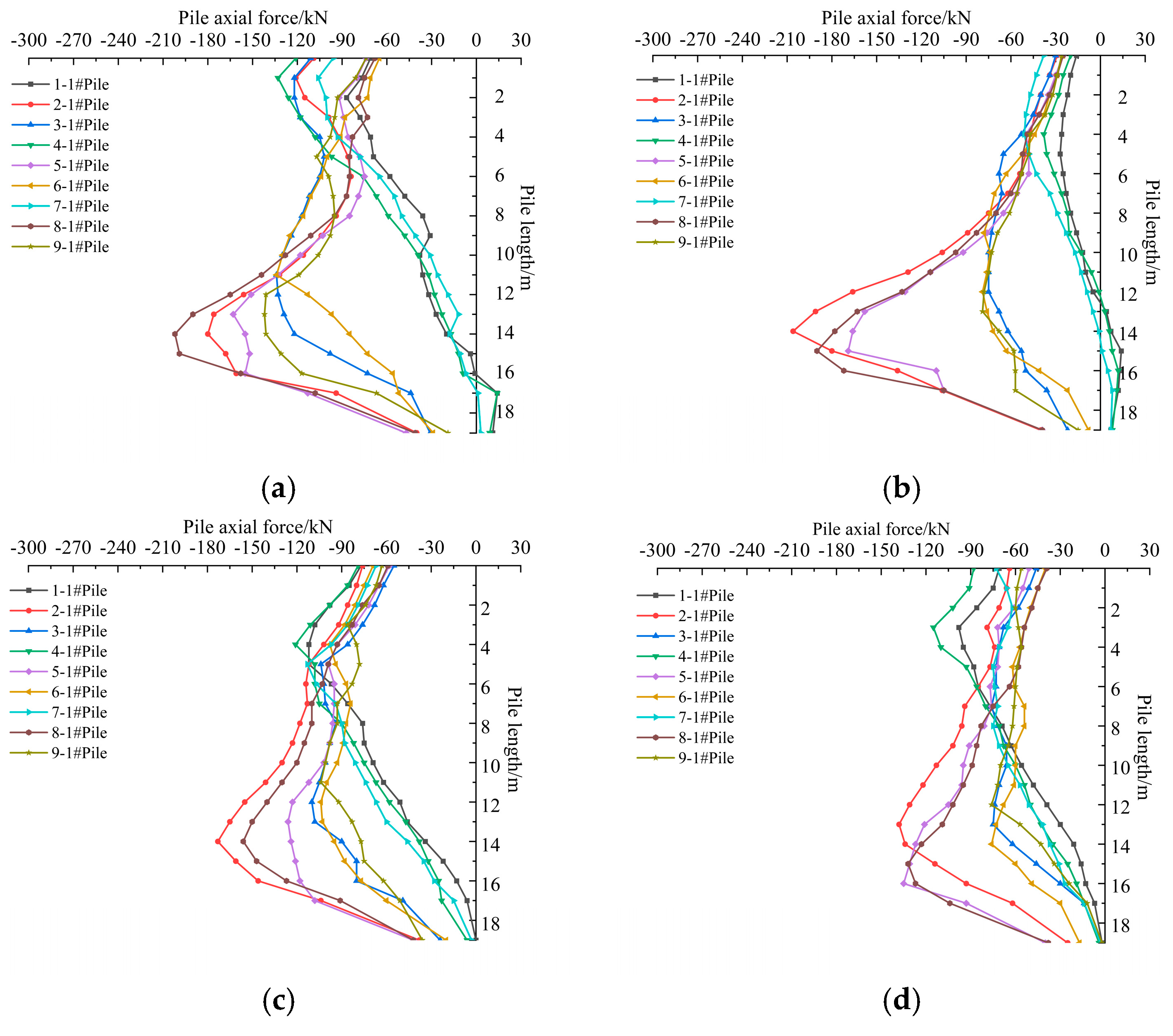
Figure 18 shows the distribution of pile axial force along the pile length for different tunnel depths after breakthrough of the twin tunnels. The results indicate that: (i) Piles in the same row exhibit similar axial-force variation. The axial force increases first and then decreases along the pile length, and the maximum axial force is located near three-quarters of the pile length. Because the middle-row piles bear a larger superposed load effect during tunnel under-crossing, their axial forces are relatively larger. (ii) With increasing tunnel depth, the maximum axial force of a single pile gradually decreases. Taking Pile 2-1# in the middle-row as an example, the maximum axial force decreases from 254.1 kN to 173.4 kN (a reduction of 31.8%).
Figure 18.
Influence of different tunnel depths on pile axial force during under-crossing construction of twin shield tunnels. (a) Case C1 (H = 23.0 m): pile axial force; (b) Case C2 (H = 24.0 m): pile axial force; (c) Case C3 (H = 25.0 m): pile axial force; (d) Case C4 (H = 26.0 m): pile axial force.
4.2.2. Effect of Pile Foundation Structure
As listed in Table 4 and shown in Figure 19, four cases (D1–D4) were designed to investigate the influence of pile foundation structure during tunnel under-crossing, corresponding to a single pile, two piles, four piles and six piles, respectively. The four-pile configuration in Case D3 is the same as that in the actual project; Case D3 is identical to Case C4 in Table 4 and is also taken as the baseline case.
Figure 19.
Numerical model for different pile foundation structures during tunnel under-crossing. (a) Case D1 (single-pile); (b) Case D2 (two-pile); (c) Case D3 (four-pile); (d) Case D4 (six-pile).
- (1)
- Ground surface settlement
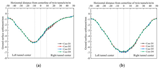
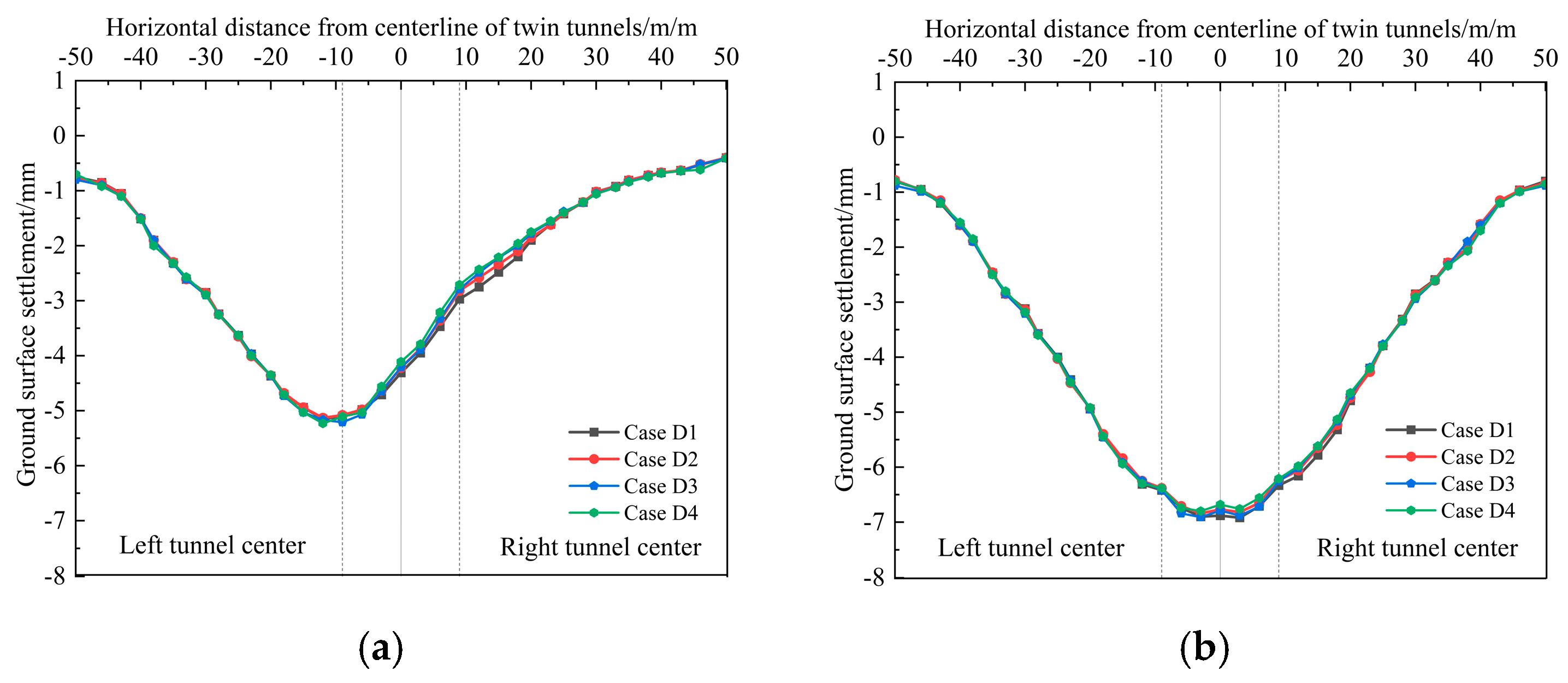
Figure 20 shows the ground surface settlement curve at Y = 45 m in the numerical model shown in Figure 6a. The results indicate that: (i) During tunnel under-crossing, the surface settlement curves for different pile foundation structures almost coincide, indicating that pile configuration has negligible influence on surface settlement. (ii) After breakthrough of the left-line tunnel, the settlement profile is V-shaped, with a maximum settlement of 5.2 mm directly above the left-line tunnel centre. (iii) After breakthrough of twin tunnels, the settlement profile becomes U-shaped, with a maximum settlement of 6.9 mm located between the right-line tunnel centre and the centreline of the twin tunnels.
Figure 20.
Influence of different pile foundation structures on ground surface settlement during under-crossing construction of twin shield tunnels. (a) Surface settlement after breakthrough of the left-line tunnel. (b) Surface settlement after breakthrough of the twin tunnels.
- (2)
- Pile lateral displacement
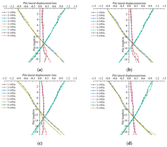
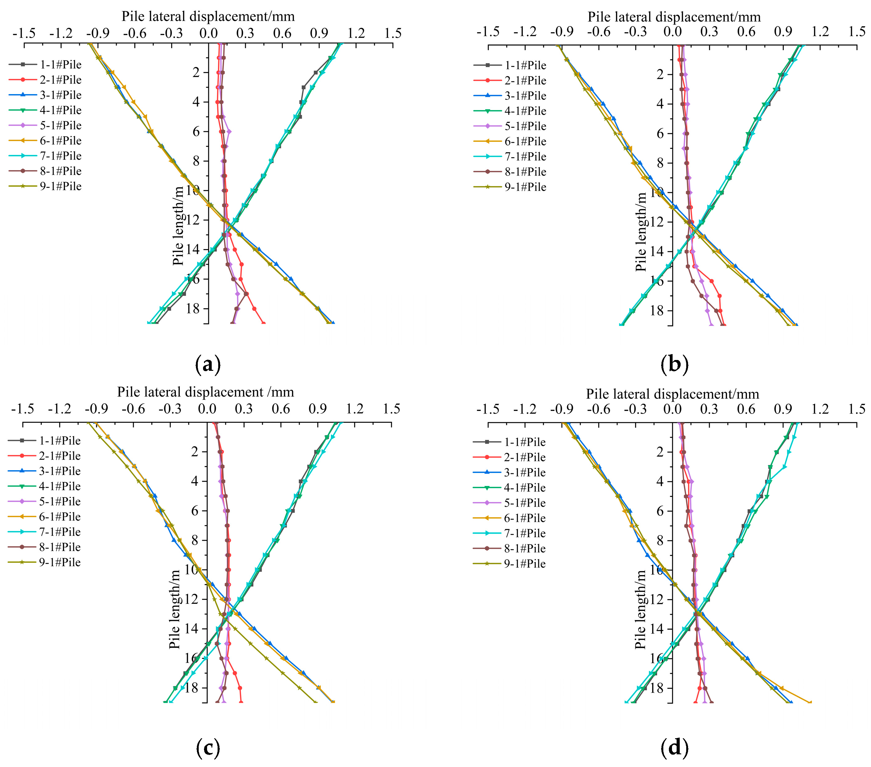
Figure 21 shows the distribution of pile lateral displacement along the pile length for different pile foundation structures after breakthrough of the twin tunnels. The lower-left pile of each pile foundation in the model shown in Figure 19 was selected for analysis. The results indicate that: (i) The lateral displacement profiles of piles in the same row are generally consistent; the left-row and right-row piles exhibit X-shaped profiles, while the middle-row piles show an overall offset toward the right-line tunnel. (ii) The differences in lateral displacement among different pile foundation structures are very small, and the maximum displacement of the pile top occurs in Pile 7-1# in the left row, with a value of 1.1 mm.
Figure 21.
Influence of different pile foundation structures on pile lateral displacement during under-crossing construction of twin shield tunnels. (a) Case D1 (single-pile): pile lateral displacement; (b) Case D2 (two-pile): pile lateral displacement; (c) Case D3 (four-pile): pile lateral displacement; (d) Case D4 (six-pile): pile lateral displacement.
- (3)
- Pile axial force
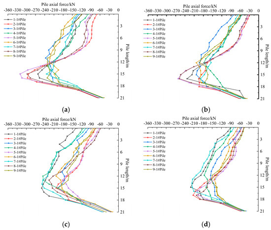
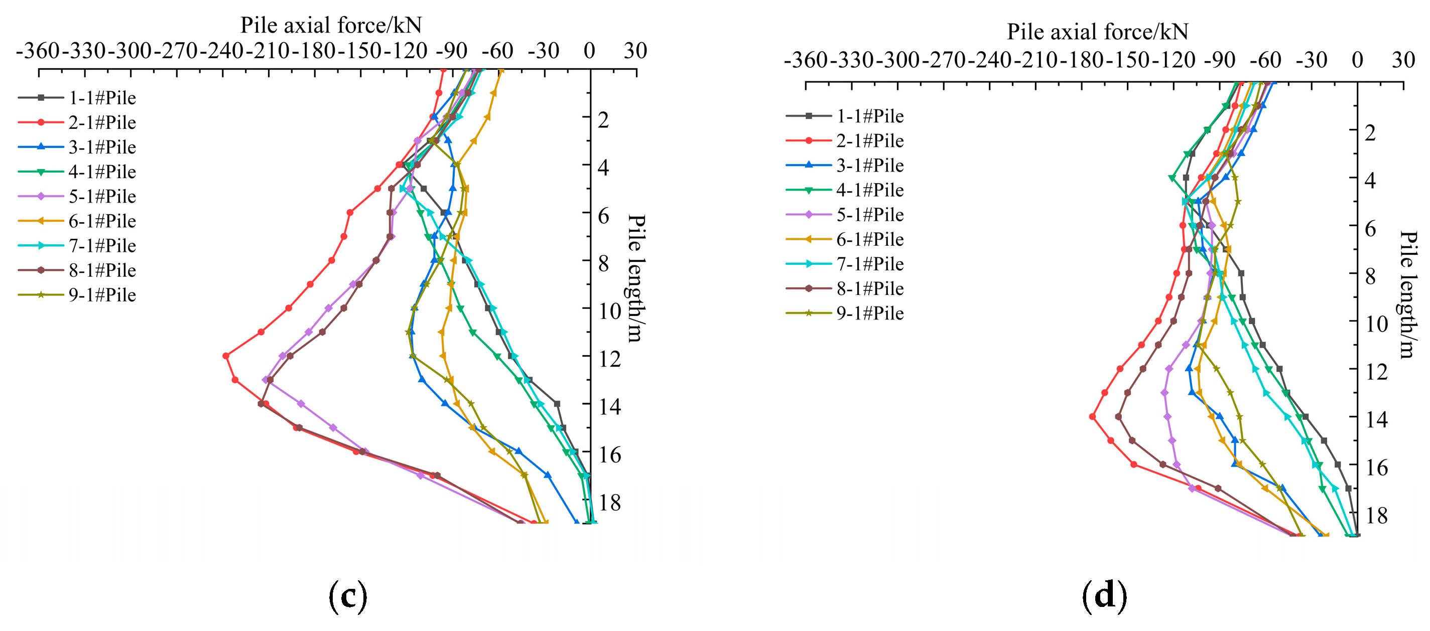
Figure 22 shows the distribution of pile axial force along the pile length for different pile foundation structures after breakthrough of the twin tunnels. The results indicate that: (i) The axial-force distribution shapes for piles in the same row are generally consistent; the axial force increases first and then decreases along the pile length, the maximum axial force is located near three-quarters of the pile length, and the axial forces of middle-row piles are relatively larger. (ii) As the number of piles increases, the maximum axial force of a single pile gradually decreases. Taking Pile 8-1# in the middle-row as an example, the maximum axial force decreases from 202.2 kN to 132.1 kN (a reduction of 34.7%).
Figure 22.
Influence of different pile foundation structures on pile axial force during under-crossing construction of twin shield tunnels. (a) Case D1 (single-pile): pile axial force; (b) Case D2 (two-pile): pile axial force; (c) Case D3 (four-pile): pile axial force; (d) Case D4 (six-pile): pile axial force.
5. Conclusions
Based on the twin shield tunnel project crossing beneath the Terminal T1 at Xinzheng International Airport, a three-dimensional numerical model validated by field monitoring data was first established. On this basis, a new numerical model was developed to systematically investigate the effects of twin shield tunnelling on existing pile foundations in a typical cohesive soil stratum under two construction modes, i.e., tunnel side-crossing and under-crossing. The influences of tunnel depth and pile foundation structure on ground surface settlement and pile responses were analysed, and the following conclusions are drawn:
- During tunnel side-crossing, ground surface settlement increases with tunnel depth, and the settlement profile evolves from a V-shape to a W-shape before and after breakthrough of the twin tunnels, with the maximum settlement increasing from 4.7 mm to 6.5 mm. When the tunnel depth decreased from above the pile tip plane, the lateral displacement profiles of left-row and right-row piles change from a spindle-shape to an X-shape, while the middle-row piles exhibit an overall offset toward the right-line tunnel. The maximum axial force in a single pile first increased and then decreased, and the maximum axial force dropped from 505.8 kN to 225.6 kN (a reduction of 55.4%).
- During tunnel side-crossing, different pile foundation structures have a limited influence on ground surface settlement. The settlement profile evolves from a V shape to a weak W shape before and after breakthrough of the twin tunnels, and the maximum settlement increases from 5.3 mm to 7.7 mm. After breakthrough of the twin tunnels, the lateral displacement profiles of piles in the left and right rows are X-shaped, and the displacement of the pile top varies slightly with a maximum of 1.9 mm. With an increasing number of piles, the maximum axial force of a single pile decreases from 320.1 kN for the single-pile case to 197.4 kN for the six-pile case (a reduction of 38.3%).
- During tunnel under-crossing, ground surface settlement increases slightly with tunnel depth, and the settlement profile evolves from a V-shape to a U-shape before and after breakthrough of the twin tunnels, with the maximum settlement increasing from 5.2 mm to 6.9 mm. The lateral displacement profiles of piles in the left and right rows are X-shaped, while the middle-row piles exhibit an overall offset toward the right-line tunnel. The displacement of the pile top increases slightly, with a maximum of 1.1 mm. The maximum axial force of a single pile shows a clear decreasing trend with increasing tunnel depth, from 254.1 kN to 173.4 kN (a reduction of 31.8%).
- During tunnel under-crossing, the pile foundation structure has no obvious effect on ground surface settlement and pile lateral displacement, the maximum ground settlement increases from 5.2 mm to 6.9 mm, and the maximum displacement of the pile top is 1.1 mm. With an increasing number of piles, the maximum axial force of a single pile decreases from 202.2 kN for the single-pile case to 132.1 kN for the six-pile case (a reduction of 34.7%).
The results of the parametric analysis in this study can provide a theoretical basis and engineering reference for predicting pile displacements and pile axial forces, optimising tunnel alignment, and controlling construction risks in similar engineering projects.
Author Contributions
Conceptualization, Q.X.; methodology, Q.X.; software, F.Y.; investigation, F.Y. and S.X.; resources, H.L.; data curation, F.Y. and X.W.; writing—original draft preparation, Q.X.; writing—review and editing, S.X. and H.D.; visualisation, Y.X.; supervision, J.C.; project administration, B.Z.; funding acquisition, B.Z. All authors have read and agreed to the published version of the manuscript.
Funding
This research was funded by the Natural Science Foundation of Henan (Grant No. 242300420017), the Natural Science Foundation of China (Grant No. 51708181), and the Fundamental Research Funds for the Henan Provincial Colleges and Universities in Henan University of Technology (Grant No. 2018RCJH11).
Data Availability Statement
The original contributions presented in this study are included in the article. Further inquiries can be directed to the corresponding authors.
Conflicts of Interest
Author Shun Xiao was employed by the company Shanghai Research Institute of Building Sciences Co., Ltd. Author Haitao Dou was employed by the company China Railway Fourth Survey and Design Institute Group Co., Ltd. The remaining authors declare that the research was conducted in the absence of any commercial or financial relationships that could be construed as a potential conflict of interest.
References
- Zhang, Y.; Saadat, Y.; Huang, H.; Zhang, D.; Ayyub, B.M. Experimental study on deformational resilience of longitudinal joint in shield tunnel lining. Struct. Infrastruct. Eng. 2024, 20, 368–379. [Google Scholar] [CrossRef] [Scilit]
- Zhang, Y.; Zhou, P.; Zhou, F.; Chen, C.; Feng, Y. Failure of urban subway segments in coastal area and reinforcement effect of bonded steel plate: A case study in China. Struct. Infrastruct. Eng. 2025, 21, 268–280. [Google Scholar] [CrossRef] [Scilit]
- Khoo, C.; Mohamad, H.; Mohamad Beddelee, A.A.A.; Thansirichaisree, P.; Ghazali, M.F.; Mohd Nasir, M.Y. Effects of advancing tunnel on a loaded pile: Numerical analysis and field measurements. J. Rock Mech. Geotech. Eng. 2025, 17, 6145–6158. [Google Scholar] [CrossRef] [Scilit]
- Zheng, G.; Wang, R.; Lei, H.; Zhang, T.; Fan, Q. Load-transfer-associated settlements of a piled building during shield tunnelling in soft ground. Tunn. Undergr. Space Technol. 2023, 133, 104964. [Google Scholar] [CrossRef] [Scilit]
- Boonyarak, T.; Phisitkul, K.; Ng, C.W.W.; Teparaksa, W.; Aye, Z.Z. Observed ground and pile group responses due to tunneling in Bangkok stiff clay. Can. Geotech. J. 2014, 51, 479–495. [Google Scholar] [CrossRef] [Scilit]
- Sirivachiraporn, A.; Phienwej, N. Ground movements in EPB shield tunneling of Bangkok subway project and impacts on adjacent buildings. Tunn. Undergr. Space Technol. 2012, 30, 10–24. [Google Scholar] [CrossRef] [Scilit]
- Gu, Q.; Zheng, R.; Yang, F.; Liu, G.; Huang, Y. An analysis of the surface settlement in the shield construction on the Ningbo urban rail transit. Hydrogeol. Eng. Geol. 2016, 43, 85–93. [Google Scholar]
- He, K.; Zhu, J.; Wang, H.; Huang, Y.; Li, H.; Dai, Z.; Zhang, J. Safety risk evaluation of metro shield construction when undercrossing a bridge. Buildings 2023, 13, 2540. [Google Scholar] [CrossRef] [Scilit]
- Kang, Y.; Geng, Z.; Chen, L.; Zhu, Y.; Li, K.; Liu, B. Ground reinforcement method for closely spaced overlapping tunnels passing beneath high-speed railway bridge. J. Geotech. Geoenviron. Eng. 2022, 148, 05022007. [Google Scholar] [CrossRef] [Scilit]
- Wang, P.; Zhou, C.; Liu, Y.; Chen, D. A study of land subsidence in the subway shield tunnel excavation in soil strata in Wuhan. Hydrogeol. Eng. Geol. 2015, 42, 75–78. [Google Scholar]
- Berthoz, N.; Branque, D.; Michalski, A.; Mohamad, W.; Bourgeois, E.; Le Kouby, A.; Szymkiewicz, F.; Rallu, A. Impact of tunnelling on piles in Parisian subsoil: Dataset of in-situ measurements in the ground and on three instrumented piles. Data Brief 2023, 47, 108971. [Google Scholar] [CrossRef] [Scilit]
- Fessler, Y.; Mignini, A.; Vargas, C.; Moreno, M.; Benito, L.; Ortiz, S. Ground control design criteria during EPB TBM tunnelling operations in sensitive urban areas-Tender Design Paris L15. In Tunnelling into a Sustainable Future–Methods and Technologies; CRC Press: Boca Raton, FL, USA, 2025; pp. 2730–2737. [Google Scholar]
- Huang, D.; Lu, W.; Luo, W.; Chen, K.; Chen, H. Experimental study on the influence of shield construction on the deformation of upper strata under load. Chin. J. Rock Mech. Eng. 2025, 44, 51–60. [Google Scholar]
- Liu, C.; Zhang, Z.; Regueiro, R.A. Pile and pile group response to tunnelling using a large diameter slurry shield: Case study in Shanghai. Comput. Geotech. 2014, 59, 21–43. [Google Scholar] [CrossRef] [Scilit]
- Mohamad, W.; Bourgeois, E.; Le Kouby, A.; Szymkiewicz, F.; Michalski, A.; Branque, D.; Berthoz, N.; Soyez, L.; Kreziak, C. Full scale study of pile response to EPBS tunnelling on a Grand Paris Express site. Tunn. Undergr. Space Technol. 2022, 124, 104492. [Google Scholar] [CrossRef] [Scilit]
- Huang, K.; Sun, Y.; Yang, J.; Li, Y.; Jiang, M.; Huang, X. Three-dimensional displacement characteristics of adjacent pile induced by shield tunneling under influence of multiple factors. J. Cent. South Univ. 2022, 29, 1597–1615. [Google Scholar] [CrossRef] [Scilit]
- Lu, H.; Shi, J.; Ng, C.W.W.; Lv, Y. Three-dimensional centrifuge modeling of the influence of side-by-side twin tunneling on a piled raft. Tunn. Undergr. Space Technol. 2020, 103, 103486. [Google Scholar] [CrossRef] [Scilit]
- Song, G.; Xu, J.; Marshall, A.M. Numerical study on the effect of protective wall depth in reducing structure deformations caused by tunnelling. Comput. Geotech. 2023, 158, 105374. [Google Scholar] [CrossRef] [Scilit]
- Soomro, M.A. 3D finite element analysis of effects of twin stacked tunnels at different depths and with different construction sequence on a piled raft. Tunn. Undergr. Space Technol. 2021, 109, 103759. [Google Scholar] [CrossRef] [Scilit]
- Wang, R.; Yan, B.; Wang, Y.; Li, K.-J. Prediction of adjacent single pile deformation induced by tunnel excavation based on the Pasternak model. Tunn. Undergr. Space Technol. 2024, 152, 105932. [Google Scholar] [CrossRef] [Scilit]
- Simic-Silva, P.T.; Martínez-Bacas, B.; Galindo-Aires, R.; Simic, D. 3D simulation for tunnelling effects on existing piles. Comput. Geotech. 2020, 124, 103625. [Google Scholar] [CrossRef] [Scilit]
- Nematollahi, M.; Dias, D. Three-dimensional numerical simulation of pile-twin tunnels interaction: Case of the Shiraz subway line. Tunn. Undergr. Space Technol. 2019, 86, 75–88. [Google Scholar] [CrossRef] [Scilit]
- Khabbaz, H.; Gibson, R.; Fatahi, B. Effect of constructing twin tunnels under a building supported by pile foundations in the Sydney central business district. Undergr. Space 2019, 4, 261–276. [Google Scholar] [CrossRef] [Scilit]
- Liu, Y.; Li, Y.; Chen, G.; Li, Y.; Li, J.; Jin, J. Theoretical Analysis of Surface Settlement During Parallel Construction of a Double-Track Tunnel with Small Spacing. Buildings 2025, 15, 1143. [Google Scholar] [CrossRef] [Scilit]
- He, C.; Wei, J.; Liang, H.; Chen, Z.; Ding, W.; Li, B. Structural Behavior Analysis for Existing Pile Foundations Considering the Effects of Shield Tunnel Construction. Buildings 2025, 15, 3263. [Google Scholar] [CrossRef] [Scilit]
- Yuan, B.; Huang, X.; Huang, Q.; Shiau, J.; Liang, J.; Zhang, B.; Zheng, J.; Fahimizadeh, M.; Sabri, M.M. Effects of Particle Size on Properties of Engineering Muck-Based Geopolymers: Optimization through Sieving Treatment. Constr. Build. Mater. 2025, 492, 142967. [Google Scholar] [CrossRef] [Scilit]
- Yuan, B.; Huang, X.; Li, R.; Luo, Q.; Shiau, J.; Wang, Y.; Yuan, J.; Sabri, S.M.M.; Huang, S.; Liao, C. Dynamic Behavior and Deformation of Calcareous Sand under Cyclic Loading. Soil Dyn. Earthq. Eng. 2025, 199, 109730. [Google Scholar] [CrossRef] [Scilit]
- Yuan, B.; Huang, Q.; Xu, W.; Han, Z.; Luo, Q.; Chen, G.; Yuan, J.; Zhang, Q.; Sabri, S.M.M. Study on the Interaction between Pile and Soil under Lateral Load in Coral Sand. Geomech. Energy Environ. 2025, 42, 100674. [Google Scholar] [CrossRef] [Scilit]
- Cao, M.; Ma, S.; Zhang, J. Numerical Analysis Study on the Influence of Shield Cutting Pile on the Settlement of Pile–Soil Composite Foundation. Adv. Civ. Eng. 2024, 2024, 5345820. [Google Scholar] [CrossRef] [Scilit]
- Ouyang, Z.; Naito, C.; Quiel, S.; Mooney, M. Strain-based design for segmental tunnel lining under thrust jack load. Struct. Infrastruct. Eng. 2025, 1–24. [Google Scholar] [CrossRef] [Scilit]
- GB 50911-2013; Technical Code for Monitoring of Urban Rail Transit Engineering. China Construction Industry Press: Beijing, China, 2014. (In Chinese)
- Jiao, N.; Ding, J.; Liao, Z.; Wan, X.; Gao, P. Impact of double shield tunnel construction on adjacent pile foundation in silty fine sand strata. J. Perform. Constr. Facil. 2025, 39, 04025033. [Google Scholar] [CrossRef] [Scilit]
- Peck, R.B. Deep excavations and tunneling in soft ground. In Proceedings of the 7th International Conference on Soil Mechanics and Foundation Engineering, Mexico City, Mexico, 25–29 August 1969; pp. 225–290. [Google Scholar]
- Hu, Y.; Tang, H.; Xu, Y.; Lei, H.; Zeng, P.; Yao, K.; Dong, Y. Ground settlement and tunnel response due to twin-curved shield tunnelling in soft ground with small clear distance. J. Rock Mech. Geotech. Eng. 2024, 16, 3122–3135. [Google Scholar] [CrossRef] [Scilit]
- Phutthananon, C.; Lertkultanon, S.; Jongpradist, P.; Duangsano, O.; Likitlersuang, S.; Jamsawang, P. Numerical investigation on the responses of existing single piles due to adjacent twin tunneling considering the lagging distance. Undergr. Space 2023, 11, 171–188. [Google Scholar] [CrossRef] [Scilit]
- Wang, G.; Fang, Q.; Wang, J.; Li, Q.; Song, H.; Huang, J. Artificial intelligence prediction of surface settlement induced by twin shields tunnelling. Tunn. Undergr. Space Technol. 2025, 161, 106606. [Google Scholar] [CrossRef] [Scilit]
- Zhou, Z.; Ding, H.; Miao, L.; Gong, C. Predictive model for the surface settlement caused by the excavation of twin tunnels. Tunn. Undergr. Space Technol. 2021, 114, 104014. [Google Scholar] [CrossRef] [Scilit]
- Soomro, M.A.; Dai, M.; Cui, Z.D.; Mangi, N.; Mangnejo, D.A.; Zhao, C. Impact of twin stacked tunnels on laterally loaded pile groups: An emphasis on settlement and load transfer mechanisms using centrifuge and numerical modelling. Structures 2024, 70, 107746. [Google Scholar] [CrossRef] [Scilit]
- Soomro, M.A.; Liu, K.; Cui, Z.D.; Mangi, N.; Mangnejo, D.A. Insights from 3D numerical simulations on the impact of tunnelling on vertical and battered pile groups under lateral loading. Comput. Geotech. 2024, 169, 106195. [Google Scholar] [CrossRef] [Scilit]
- Song, G.; Marshall, A.M. Tunnel-piled structure interaction: Numerical simulation of hybrid centrifuge test. Comput. Geotech. 2021, 140, 104477. [Google Scholar] [CrossRef] [Scilit]
- He, S.; Lai, J.; Li, Y.; Wang, K.; Wang, L.; Zhang, W. Pile group response induced by adjacent shield tunnelling in clay: Scale model test and numerical simulation. Tunn. Undergr. Space Technol. 2022, 120, 104039. [Google Scholar] [CrossRef] [Scilit]
- Soomro, M.A.; Mangi, N.; Cui, Z.D.; Liu, K.; Mangnejo, D.A. Evaluation of response mechanisms in an elevated pile group subjected to lateral loading caused by twin-tunnelling. Comput. Geotech. 2024, 171, 106334. [Google Scholar] [CrossRef] [Scilit]
- Soomro, M.A. Influence of twin stacked tunnels on the performance of laterally loaded pile group. Can. Geotech. J. 2025, 62, 1–23. [Google Scholar] [CrossRef] [Scilit]

Disclaimer/Publisher’s Note: The statements, opinions and data contained in all publications are solely those of the individual author(s) and contributor(s) and not of MDPI and/or the editor(s). MDPI and/or the editor(s) disclaim responsibility for any injury to people or property resulting from any ideas, methods, instructions or products referred to in the content. |
© 2026 by the authors. Licensee MDPI, Basel, Switzerland. This article is an open access article distributed under the terms and conditions of the Creative Commons Attribution (CC BY) license.