


Abstract
With the increasing development in urban underground spaces towards greater depth, scale, and complexity, the prediction and control of deformations in deep excavation engineering have become critical challenges in geotechnical engineering. This study investigates the ultra-deep excavation of the Tianjin Metro Line 8 Liulitai Station, analyzing the deformation characteristics of the retaining structure during top-down construction in soft soil based on field monitoring data. The results reveal a typical “bulging” pattern in the horizontal displacement of the diaphragm wall, which accumulates progressively with excavation depth. To enhance deformation prediction accuracy, a self-developed beam-plate finite element method (BPFEM) platform, implemented in Python (version 3.11.9), is introduced. The platform integrates code-specified analytical methods and the incremental approach to simulate the internal forces and deformations of the support system with high precision. By incorporating a dual-parameter back-analysis technique—adjusting both the horizontal subgrade reaction modulus and active earth pressure—the numerical model achieves significantly improved agreement with monitoring data. The proposed method demonstrates strong predictive capability, with a maximum error of only 4.4% in subsequent construction stages, confirming its feasibility and reliability for deformation forecasting in top-down deep excavations. The BPFEM framework and parameter inversion strategy presented herein provide an effective technical basis for intelligent prediction and dynamic control in deep excavation projects under complex geological conditions.
1. Introduction
With the rapid advancement of urbanization, the development and utilization of underground space have been increasing steadily. As an essential component of urban transportation systems, metro stations and their excavation constructions constitute a critical part of underground infrastructure construction. Correspondingly, excavation methods for excavations have evolved into several commonly used construction approaches, such as the top-down method and the bottom-up method. As urban buildings become increasingly dense, the surrounding environment of excavations has grown more complex, and the safety of excavation has therefore attracted widespread attention [1,2,3]. Meanwhile, the ever-increasing demands of urbanization have led to greater excavation depths in excavation engineering, which in turn makes deformation control progressively more challenging. Therefore, it is of great practical significance to investigate the deformation characteristics of deep excavations in soft soil areas and to develop effective methods for deformation prediction [4,5,6].
The entire excavation process includes several key stages, such as the construction of the retaining structure, earth excavation, installation of supports, and support removal [7]. In recent years, relatively mature research has been achieved regarding the deformation characteristics of retaining structures during deep excavation in soft soil regions. Using statistical analysis of field monitoring data, Tan et al. [7,8,9], focusing on an ultra-deep and large-area excavation project, investigated the deformation control performance of a synchronized cross-construction method combining top-down [10,11] and bottom-up [12,13,14] procedures and proposed corresponding deformation control measures. Based on statistical analysis of monitoring data throughout the full construction process, Fan et al. [15] collected the well-documented field data of 20 deep excavations for the construction of Nantong Metro Line One buried in the water-rich sandy strata to establish an excavation database, and statistical analyses were performed for both lateral wall displacements and ground settlements. Liu et al. [16] explored the deformation characteristics of an ultra-deep and small-scale excavation through a comprehensive instrumentation program; the results indicated that the upper boundary was significantly smaller owing to the spatial effect. Relying on an ultra-deep excavation case in Hangzhou, Tao et al. [17] conducted a refined statistical analysis of the deformation characteristics of diaphragm walls throughout the entire construction process. They found that the maximum lateral displacement occurred at a depth of approximately 0.8 times the excavation depth, and that the casting of the excavation base slab did not affect the location of the maximum lateral displacement, but only caused a slight increase in its magnitude. Through numerical simulation, Arslan et al. [18] established a numerical analysis model for the full construction process of an excavation project in Izmir and statistically analyzed the soil–structure interaction and excavation-induced deformations. The results showed that soil excavation was the key stage inducing diaphragm wall deformation. Many scholars [18,19,20,21,22], based on actual excavation projects and using three-dimensional finite element analysis, have compared simulated results with field measurements. Their findings indicate that retaining wall deformation is significantly influenced by the aspect ratio of the excavation; deformation on the short side is relatively small because of the restraining effect of corner bracing, i.e., the “corner effect” [19,20,22,23].
Effective and accurate prediction of excavation deformation based on field monitoring data is of great practical significance for ensuring excavation safety. To overcome the shortcomings of traditional prediction methods, and with the rapid development of neural networks, many scholars have explored a variety of deformation prediction approaches. Among them, deep neural networks have demonstrated superiority in excavation-induced deformation prediction [24,25,26,27,28,29,30,31,32,33], particularly in terms of high accuracy and strong generalization ability. In addition, hybrid neural networks that integrate multiple network architectures have achieved remarkable results in excavation deformation prediction. Yang et al. [27] proposed a graph recurrent neural network (GRNN)-based spatio-temporal imputation framework designed to enhance the reliability of automated excavation monitoring systems. Li et al. [28] employ a numerical simulation and deformation prediction method combining PLAXIS 3D and the Back Propagation (BP) neural network and Particle Swarm Optimization (PSO), which effectively enhances the convergence speed of the BP neural network model and avoids the issue of easily falling into local optimal solutions. Jiang et al. [34] proposed a CNN-based evaluation model for damage that is able to capture the key features representing the failure mechanisms under random soil conditions. Yang et al. [35] utilized a Gated Recurrent Unit Neural Network to predict the deformation responses for braced excavations. Deng et al. [29] develop a dynamic approximation optimization framework integrating MSD and a multi-receptive field convolutional neural network (MRFN) to predict the deflections of retaining walls in multi-stage excavations. Besides, Bouhacina [36] proposed a novel TOARS-Optimized method to predict soil parameters, and the result showed accurate and stable performance. Their results showed that the model demonstrated significant advantages in both accuracy and stability. Although neural networks have shown strong accuracy and versatility in excavation deformation prediction, they tend to overlook the intrinsic physical mechanisms governing the behavior of retaining structures during excavation. In contrast, although numerical simulation methods based on solid elements can provide relatively accurate deformation results by employing advanced constitutive models, their computational efficiency is relatively low and the time cost is high.
This study will rely on a practical engineering case—the excavation of the Liulitai subway station pit for Tianjin Metro Line 8—focused on analyzing the deformation characteristics of the retaining structures in standard segment intervals based on measured data. Furthermore, utilizing the elastic resistance method for pit deformation calculation as specified in current regulations [37], along with the incremental method for calculating deformation in multi-support pits, a bar and face element finite element method (BPFEM) software has been developed using Python (version 3.11.9). Recent advances in numerical simulation and data-driven approaches have improved deformation prediction for deep excavations. However, conventional solid-element finite element analysis is computationally intensive and unsuitable for rapid engineering evaluation, while existing commercial design software mainly enables fast calculation under predefined conditions but lacks predictive capability for unexcavated scenarios. To address this gap, this study proposes a simplified finite element method, BPFEM, which enables rapid three-dimensional deformation simulation while maintaining sufficient accuracy through parameter back-analysis calibration. To address the issues of untimely and inaccurate risk warning in deep excavation projects [38,39], a soil parameter inversion technique and a pit deformation prediction method based on BPFEM are proposed, supported by a demonstration application of the engineering case presented in this paper.
2. Engineering Background
2.1. The Introduction of Excavation
Liulitai Station is an underground station comprising four levels, located west of the intersection of Anshan West Road and Weijin Road. To the north of the station are the Tianjin University Tianjin Financial Technology Company, the Architectural Design and Research Institute at Tianjin University, and the faculty dormitories of Beiwucun at Tianjin University. To the south, there are the Tianjin University Beiyang Technology Development Company, the north gate of Tianjin University, and the Tianjin University Sports Center. The west side features the Toyota Bridge (a pedestrian overpass), while the east is bordered by the Weijin River and Liulitai Bridge. The main body of the station is situated beneath Anshan West Road. The surrounding environment is complex, and the traffic is heavy.
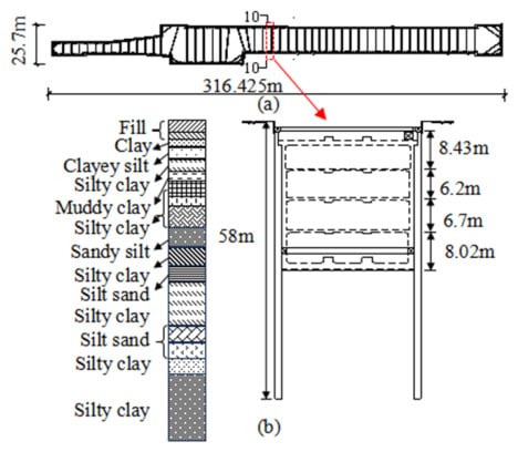
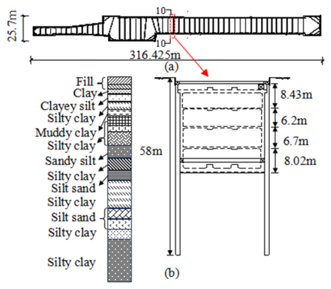
The excavation project employs a top-down construction method for the station pit, utilizing a diaphragm wall with internal bracing as the retaining structure, with a wall thickness of 1200 mm. The total length of the station is 316.425 m, with a standard width of 23.7 m and a depth of 31.254 m. The shield tunneling pit measures 28.3 m in width and 32.94 m in depth, with the shield tunneling pit located at the ends of the station. The standard wall length is approximately 58 m, and the standard plan and cross-sectional view of the station pit are illustrated in Figure 1.
Figure 1.
Schematic diagram of the excavation plan and cross-section: (a) Plan view; (b) Cross-sectional view.
2.2. Geological Conditions
The project site, with an overburden depth exceeding 80 m, is divided into four hydrogeological rock groups, including an unconfined aquifer group, the first confined aquifer group, the second confined aquifer group, and the fourth confined aquifer group. The site features special soils primarily consisting of artificial fill and soft soil. The artificial fill is categorized into mixed fill and cohesive fill. The mixed fill predominantly comprises bricks, concrete debris, gravel, household waste, and other excavated materials, characterized by heterogeneous soil quality, loose structure, and relatively poor engineering properties, with thickness generally ranging from 1.40 to 4.10 m, while localized thickness can reach up to 5.40 to 10.50 m. The cohesive fill is distributed inconsistently, with thicknesses spanning from 0.90 to 4.00 m.
The artificial fill exhibits poor structural quality and uniformity, suggesting that careful consideration should be given during design and construction to potential adverse impacts on pit support, groundwater dewatering, the construction of diaphragm wall slots, and ground settlement stability.
The soft soil mainly consists of muddy clay and silty clay within the marine sedimentary strata of the Quaternary Zhongzu formation. These sediments are embedded at depths ranging from 5.90 to 12.50 m and contain interbedded layers of silty soil lenses. They appear gray, are in a plastic state, lack layering, contain shell fragments, and are classified as highly compressible soil, exhibiting low strength.
This study focuses on the standard segment interval located within the profile indicated by the red dashed box in Figure 1a. The soil layer parameters for this profile are presented in Table 1.
Table 1.
Soil parameters.
3. Field Measurement-Based Analysis of Deformation Characteristics of the Retaining Structure
3.1. Deformation Characteristics of the Diaphragm Wall in the Standard Section
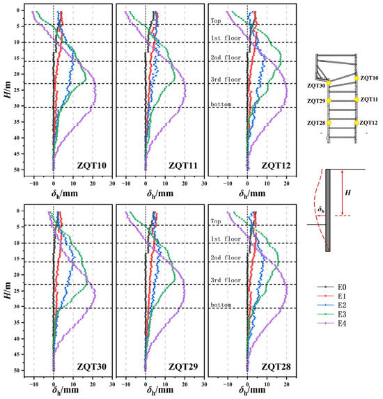
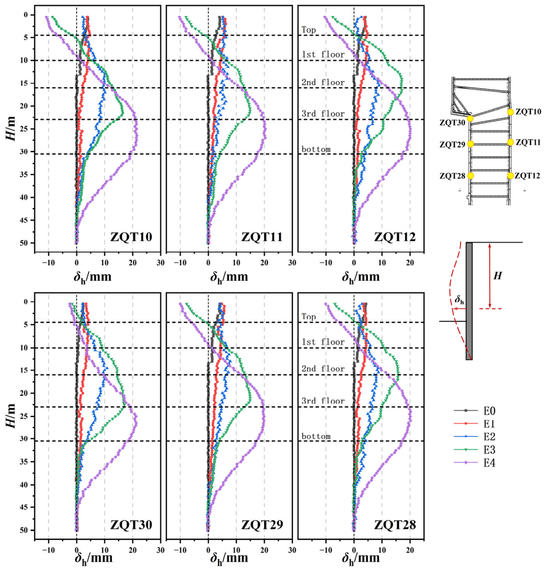
As shown in Figure 2, the lateral displacement profiles of the diaphragm wall at different construction stages during the top-down construction of a deep excavation are presented. In the figure, the horizontal axis, δh, denotes the lateral displacement of the diaphragm wall, while the vertical axis, H, represents the depth along the wall. Overall, the diaphragm walls on both the north and south sides exhibit a typical “bulging” deformation pattern at all construction stages, and the lateral displacement increases progressively with the excavation depth. The displacement curves at all monitoring points indicate that the primary deformation zone is concentrated in the middle–lower portion of the excavation, approximately within a depth range of 20–30 m. Within this depth interval, the soil mass is located in the transition zone between active earth pressure and passive earth pressure, where the gradient of earth pressure reaches its maximum, thereby driving the wall to deform laterally toward the excavation. Meanwhile, the stiffness of the diaphragm wall in the middle–lower section is relatively uniform; the top is significantly restrained by the top slab, while the bottom is strongly constrained by embedment and the base slab. Consequently, the middle–lower portion between the top and bottom slabs becomes the region where lateral deformation is most pronounced.
Figure 2.
Lateral Displacement Profiles of the Diaphragm Wall. Notes: E0: overburden layer excavation; E1: 1st floor excavation; E2: 2nd floor excavation; E3: 3rd floor excavation; E4: 4th floor excavation.
As the excavation progresses from the overburden layer down to Basement Level −4, the maximum lateral displacement of the diaphragm wall exhibits a pronounced cumulative increase under the influence of staged unloading effects. The maximum lateral displacements at each stage are approximately 5 mm, 5 mm, 10 mm, 15 mm, and 20 mm, respectively. Excavation at each soil layer disrupts the initial earth pressure equilibrium, resulting in a significant reduction in the soil pressure inside the excavation, while the passive earth pressure of the soil outside the excavation continues to act on the wall, thereby causing a progressive accumulation of deformation. The diaphragm wall at all monitoring points displays a similar “bulging” deformation pattern, and the wall deflection becomes increasingly pronounced with increasing excavation depth.
Except for monitoring point ZQT30, the wall tops at the remaining monitoring points exhibit varying degrees of outward inclination toward the outside of the excavation, mainly concentrated in the zone above the Basement Level −1 slab. In contrast, at monitoring point ZQT30, which is located at the corner of the excavation, the outward (negative) deformation at the wall top is significantly restrained due to the support provided by the diaphragm wall perpendicular to the longitudinal side. However, in the middle portion of the wall (approximately 20–30 m depth), the inward-bulging deformation toward the excavation is slightly larger than that observed at non-corner monitoring points on the same side. This depth-dependent behavior at the corner can be explained as follows: (1) At shallow depths, the bidirectional restraint from the two intersecting diaphragm walls effectively limits outward tilting; (2) At greater depths, the corner region experiences stress concentration due to the superposition of active earth pressures from both sides of the excavation, while the passive zone soil springs are less effective because of the corner geometry, resulting in a locally increased bulging deformation. This phenomenon suggests that the conventional “corner effect” (reduced deformation at corners) is depth-dependent and may not fully apply to the middle–lower portion of ultra-deep excavations in soft soils.
The overall deformation pattern indicates that, after the formation of the multi-level slab constraints in the top-down construction system, the lateral deformation of the diaphragm wall tends to stabilize, demonstrating the effective integrity and synergistic performance of the support system.
3.2. Evolution of Peak Lateral Displacement of the Diaphragm Wall
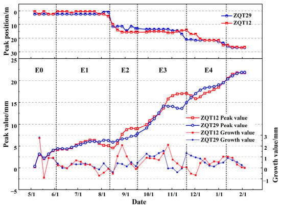
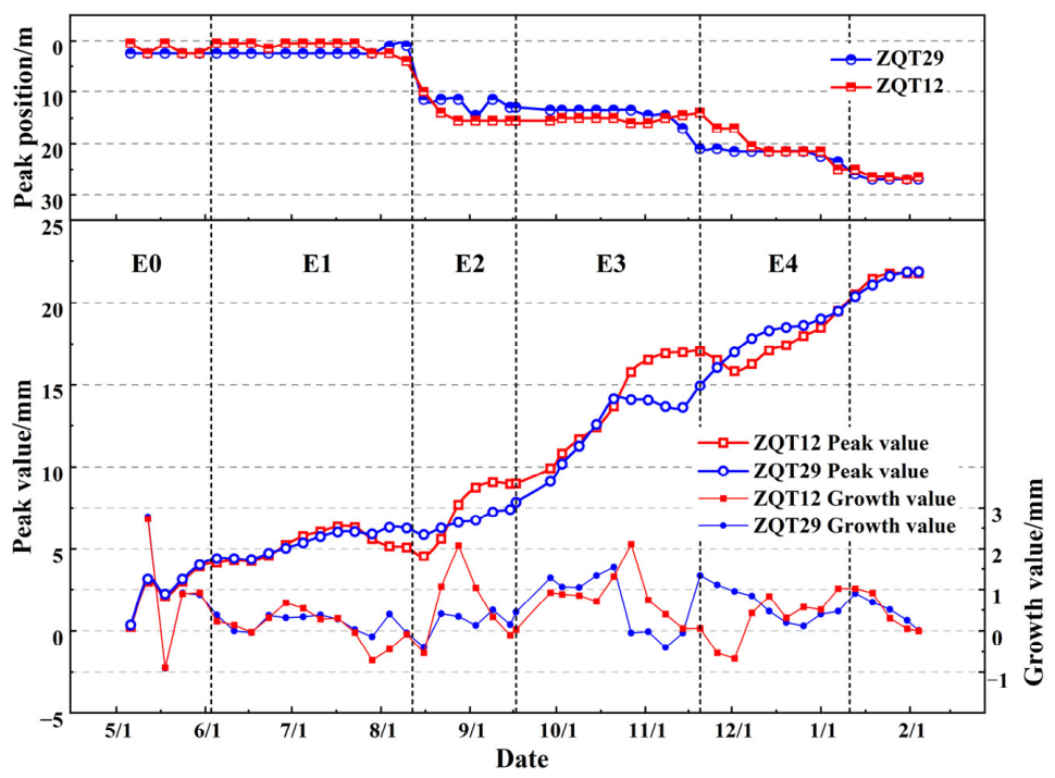
As shown in Figure 3, the time-dependent evolution curves of the peak lateral displacement, increment of peak displacement, and peak position of the diaphragm wall at monitoring points ZQT12 and ZQT29 during the top-down construction of a deep excavation are presented. Overall, the peak lateral displacement of the diaphragm wall increases progressively with excavation and exhibits pronounced stage-dependent characteristics. During the excavation of the overburden layer and Basement Level −1, the peak displacement changes slowly and remains relatively small, as the embedment depth of the wall is significantly greater than the excavation depth, resulting in a limited influence on the lateral stress state of the wall. After excavation to Basement Level −2, the peak displacement increases markedly, and the growth rate further accelerates during the excavation of Basement Levels −3 and −4, with the peak value eventually stabilizing at over 20 mm. This trend indicates that the increasing excavation depth continuously disrupts the stress equilibrium of the wall, and the cumulative effect of earth pressure from the soil outside the excavation becomes increasingly significant. In general, this stage-wise growth pattern reflects a “depth-dependent cumulative effect” during deep excavation, whereby the unloading of the soil mass accumulates with increasing excavation depth, leading to a continuous increase in lateral wall displacement.
Figure 3.
Time-dependent curves of peak lateral displacement characteristics of the diaphragm wall at monitoring points ZQT12 and ZQT29.
A comparison between different monitoring points shows that the lateral displacement at ZQT12 is more fluctuating and less stable than that at ZQT29, indicating that spatial location has a notable influence on wall deformation. ZQT12 is located at the central straight section of the diaphragm wall, where the surrounding soil properties are relatively uniform and more susceptible to construction disturbance and stress redistribution within the excavation. In contrast, ZQT29 is situated near the corner region of the diaphragm wall, where stronger structural and boundary constraints restrict the lateral deformation of the wall. This difference not only reflects the spatial heterogeneity of excavation-induced deformation in soft soil regions, but also highlights the influence of geometric boundary conditions on structural deformation.
From the temporal evolution of the peak position, both ZQT12 and ZQT29 exhibit a progressive downward migration of the peak depth with the advancement of excavation. During the excavation of the overburden layer and Basement Level −1, the peak is concentrated within the shallow zone above 10 m depth. Starting from Basement Level −2, the peak position shifts downward in stages and stabilizes at a depth of approximately 30 m during the excavation of Basement Level −4. This phenomenon indicates that, with increasing excavation depth, the zone of soil pressure release extends deeper, and the governing zone of wall deformation correspondingly migrates downward. Consequently, the middle–lower portion of the wall (approximately 20–30 m depth) gradually becomes the dominant deformation zone. This characteristic reveals the “depth-oriented” nature of lateral deformation of diaphragm walls in deep excavations, providing important engineering references for monitoring and reinforcement of support systems, and further confirming the stage-dependent and spatially distributed deformation control characteristics of the top-down construction system in soft soil conditions.
4. Establishment of BPFEM Model
4.1. Theory of BPFEM
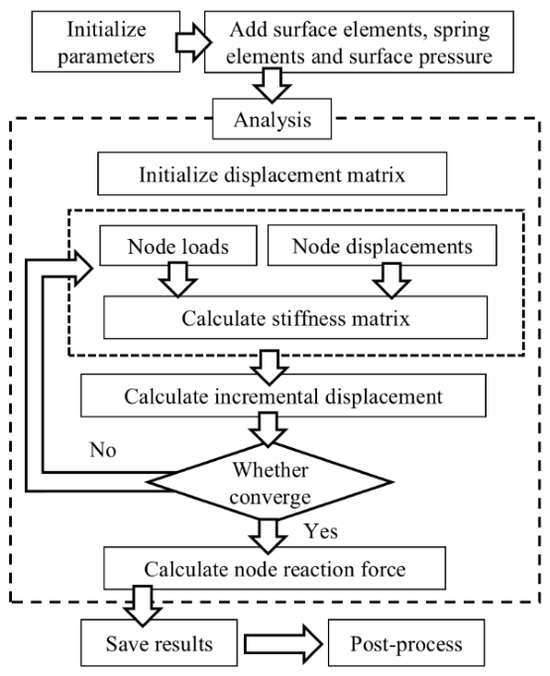
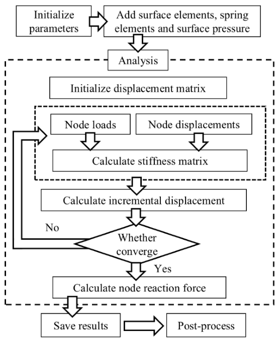
The calculation flowchart of the BPFEM is depicted in Figure 4, including pre-processing, analysis and post-processing. In this section, the calculation theory of BPFEM is specified.
Figure 4.
The calculation flowchart of BPFEM.
4.1.1. Pre-Processing
The proposed beam-plate finite element method (BPFEM) is based on the open-source structural analysis software PyNite (https://pynite.readthedocs.io/en/latest/). The novelty of this study lies in the development of a step-by-step deep excavation calculation module and a post-processing module for visualization. The core simulation process relies on PyNite’s well-established finite element analysis algorithms. Therefore, fundamental principles of finite element analysis are not detailed in this section. Additionally, the computational framework for excavation retaining structures is implemented based on the Chinese deep excavation design code [37] (JGJ120-2012), using the following governing equations:
where M is the bending moment of the retaining pile; E is the Young’s modulus of the retaining pile; I is the inertia of the retaining pile; ρ is the curvature of the retaining pile; z is depth; x is the horizontal deformation; Q is the shearing force in the retaining pile; eak is the earth pressure in the active zone; kp is the soil spring stiffness in the passive zone, where kp = m·z, and m is the coefficient of subgrade reaction; bs is the calculating width in the active zone, which equals the spacing between retaining piles; b0 is the calculating width of the soil in the passive zone, where b0 = 0.9(1.5d + 0.5), and d is the diameter of the retaining pile; zsi is the depth of the i th level of strut; Ksi is the horizontal stiffness of the strut in unit width; xm Zsi is the horizontal deformation in case m at the elevation of the i th level of strut; T0i is the prestressed force in the strut; zL is the depth of the pile toe; MZL is the bending moment of the pile toe; Kθ is the bending stiffness of the pile toe.
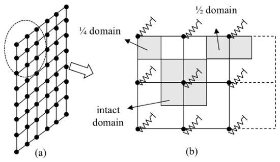
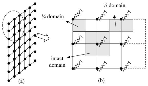
In the simulation, the earth pressure in the active zone is calculated by Rankine’s earth pressure theory, while the soil in the passive zone is equated to passive springs, as illustrated in Figure 5. For each grid point in the diaphragm wall, the algorithm automatically identifies adjacent grid points and calculates the area of the rectangular region formed by their envelope. The equivalent supporting area of each spring is determined by dividing this area by 4, and the spring stiffness is computed by multiplying the stiffness per unit area by the supporting area.
Figure 5.
Schematic of soil spring stiffness calculation: (a) Schematic diagram of the surface mesh; (b) Schematic diagram of the spring stiffness calculation domain.
Beam elements can be employed to simulate braced pile-supported excavation systems with internal struts, whose stiffnesses can be calculated by Equation (6) and are shown in Table 2 along with the excavation process. Besides, plate elements are used to model the mechanical response and deformation behavior of diaphragm walls.
where Ks is the stiffness of strut; α is the support-relaxation coefficient; E is the modulus of elasticity; A is the cross-section area; λ is the fixed-point adjustment factor, 0.5 by default; L is the length of struts; s is the strut spacing; θ is the angle between the strut and the waler beam.
Table 2.
Excavation process and strut stiffness.
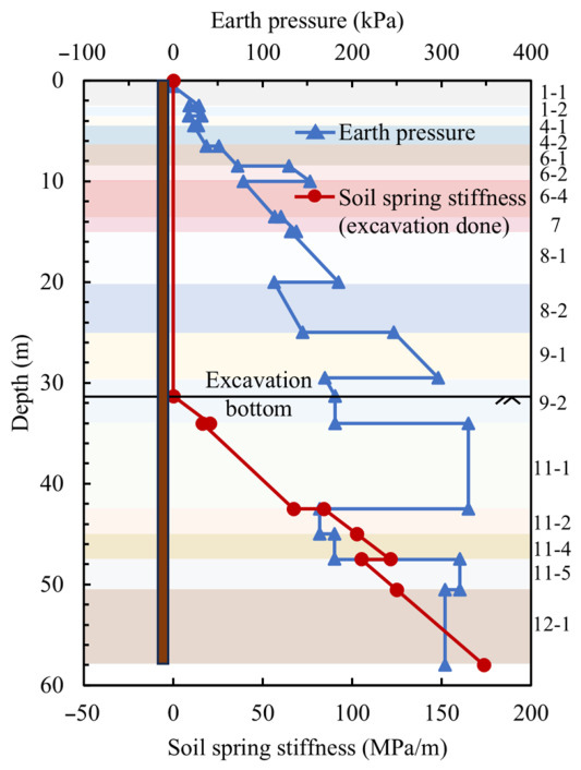
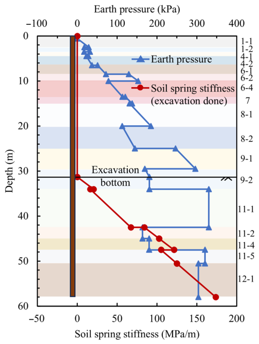
The PyNite (https://pynite.readthedocs.io/en/latest/) program incorporates built-in formulations for plate element analysis, allowing surface loads to be applied directly to plate elements to represent the earth pressure in the active zone, while soil springs are introduced to simulate the passive soil resistance in the passive zone. The BPFEM program automatically calculates the active earth pressure and the stiffness of passive soil springs based on user-defined soil parameters. The active earth pressure is determined according to Rankine earth pressure theory, and the stiffness of soil springs can be automatically updated under different excavation stages. Based on the engineering case adopted in this study, input parameters include soil stratification information such as the number of soil layers, layer thickness, soil friction angle, soil cohesion, and soil density, as well as structural and construction information including strut installation elevations, strut stiffness, diaphragm wall properties, and excavation depths for each construction stage. The calculated active earth pressures and passive soil spring stiffnesses are presented in Figure 6.
Figure 6.
The earth pressure and soil spring stiffness when soil is excavated to the bottom.
4.1.2. Step-by-Step Excavation Calculation
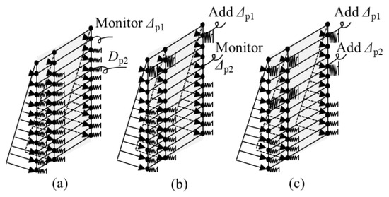
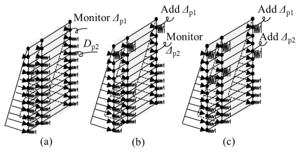
After inputting the parameters, the earth pressure in the active zone and soil springs in the passive zone are applied. The primary FEM calculation process is integrated into PyNite, as shown in Figure 4. Since the core calculations in PyNite are based on a stable equilibrium approach and do not support incremental calculations, additional procedures have been implemented to simulate step-by-step excavation. As illustrated in Figure 7, a displacement load module has been developed to perform incremental displacement calculations, accounting for both excavation and strut installation. Initially, it is assumed that the piles are undeformed before excavation, with earth pressure applied in the active zone and soil springs in the passive zone. Excavation is simulated by progressively removing soil springs in the passive zone. After excavating the first layer of soil, the displacement at the first layer of struts, denoted as Δp1, is monitored and incorporated before the second excavation step. Similarly, after the second excavation step, the displacement at the second layer of struts, Δp2, is monitored. Before removing the third layer of soil springs, the displacements Δp1 and Δp2 are accounted for, along with the installation of the second layer of strut springs. These preset displacements can account for the displacement of the diaphragm wall at the location of struts before installing the struts.
Figure 7.
Excavation simulation process: (a) First step of excavation; (b) installing the first layer of struts and second step of excavation; (c) installing the second layer of struts and third step of excavation.
4.1.3. Post-Processing
A module for outputting calculation results was developed, which enables the output of calculation results for target operating conditions in text format, including results such as the deformation and internal forces of the retaining structure.
The proposed BPFEM is essentially a simplified finite element simulation method based on the classical elastic resistance method for excavation analysis. Instead of modelling the entire soil domain as continuum elements, the active earth pressure is simplified as linear loads, while the soil in the passive zone is represented by soil springs. This simplification significantly reduces computational scale and enables rapid three-dimensional deformation prediction. Combined with the proposed parameter back-analysis strategy, the method allows fast model calibration and efficient excavation deformation analysis compared with conventional FEM approaches.
4.2. Verification of BPFEM Model
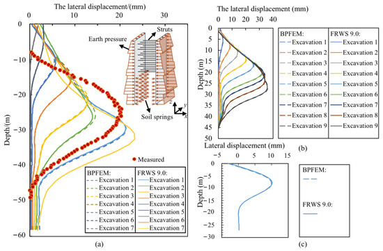
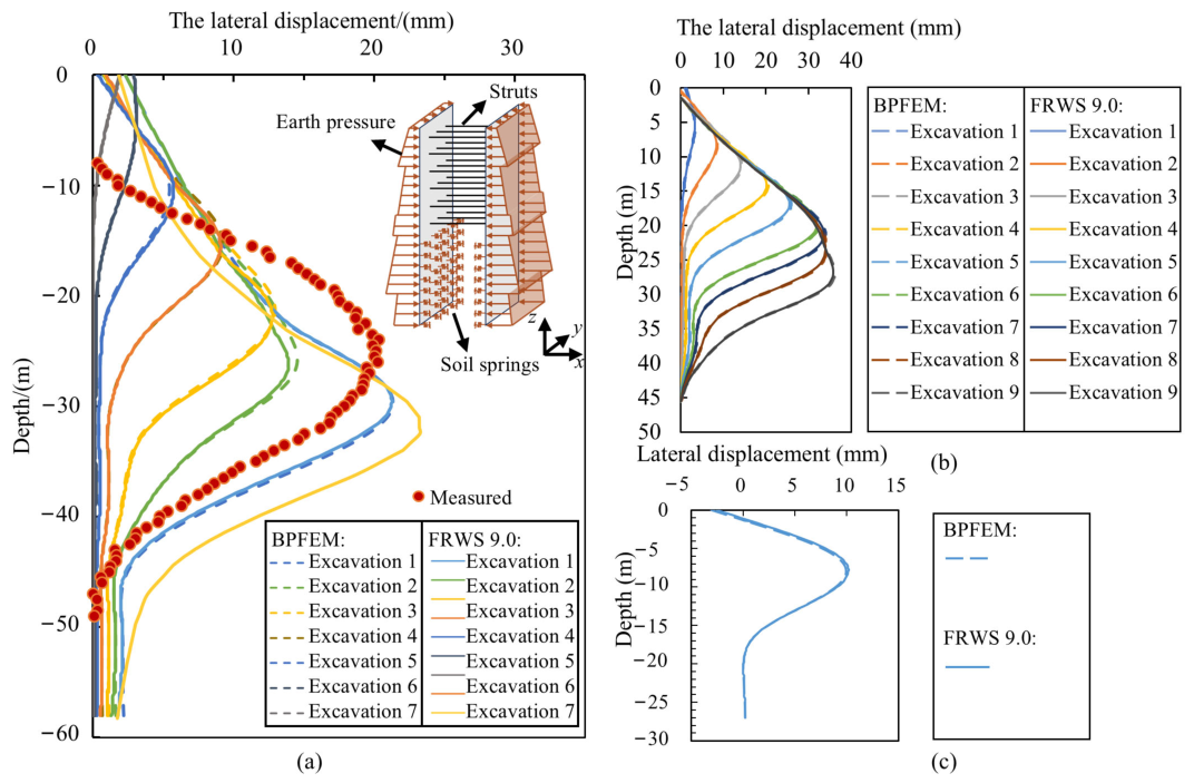
Based on the BPFEM, a wall–strut excavation model was established using cross-section 10 (shown in Figure 1) of the Liulitai Metro Station excavation as the reference engineering case. To verify the computational accuracy of the developed beam–plate finite element program, validation analyses were conducted using the same parameter settings as those adopted in FRWS 9.0. The mesh size of the plate was set as 0.5 m. The deformation of the retaining structure and the schematic diagram of the numerical model are shown in Figure 8a. The nodal degrees of freedom of the edge elements along the side wall are constrained in the x-direction displacement, z-direction displacement, and rotation about the y-axis. As indicated in the figure, the diaphragm wall displacement and bending moment obtained from the BPFEM agree closely with the results computed by the FRWS 9.0, with only negligible discrepancies. These results demonstrate the accuracy and reliability of the finite element method adopted in this study. Important to mention, the proposed BPFEM is a simplified excavation analysis approach that implements the elastic resistance method within a finite element framework to improve computational efficiency rather than to replace advanced constitutive FEM models. Therefore, direct comparison with solid-element FEM analyses using sophisticated constitutive laws is not appropriate due to fundamental differences in modeling philosophy. Validation is conducted in two aspects: first, comparison with the commercial software FRWS 9.0, which adopts the same elastic resistance theory, to verify the correctness of the method implementation; second, comparison between predicted deformation under unexcavated conditions and field measurements to demonstrate the reliability of the proposed prediction framework in Section 4.3.2.
Figure 8.
The comparison between BPFEM and FRWS 9.0: (a) Liulitai Metro Station excavation; (b) a strutted wall-retaining excavation case in Singapore; (c) a propped pile-retaining excavation in Hangzhou, China.
Additionally, to further evaluate the robustness of the proposed BPFEM, two additional engineering cases were analyzed using the same modeling framework. BPFEM models were established under different project conditions, and the results were compared with those obtained from the commercial software FRWS 9.0 using identical parameters. As shown in Figure 8b,c, the calculated deformation responses showed close agreement between the two approaches, confirming the accuracy and reliability of embedding the elastic resistance method within the finite element framework. These additional validations demonstrate that the proposed method maintains stable performance and good applicability across different engineering scenarios. As shown in Figure 8a, the simulated displacement of the retaining piles is generally lower than the measured data (e.g., Figure 3). This discrepancy is primarily attributed to the soil pressure calculation method, which is more applicable to shallow excavations. The earth pressure distribution for ultra-deep excavations, as in this study, remains an area of ongoing research and development. Additionally, the most sensitive parameter influencing lateral wall displacement is the coefficient m of the soil, which is directly related to soil spring stiffness and is calculated following Equation (7). However, this parameter is mostly determined based on engineering experience, leading to inherent discrepancies between simulation results and field measurements.
where ∆ is the estimated bottom displacement of the excavation; φ is the soil friction; c is the soil cohesion.
Therefore, calibration of soil parameters and refinement of the active earth pressure are of critical importance. By validating the numerical simulation results against field monitoring data from the actual project, the back-calculated parameters and earth pressure distributions can more realistically represent in situ conditions, thereby improving the reliability of subsequent excavation deformation predictions under later excavation stages.
4.3. The Prediction Method for Wall Deformation
4.3.1. Parameter Back-Analysis
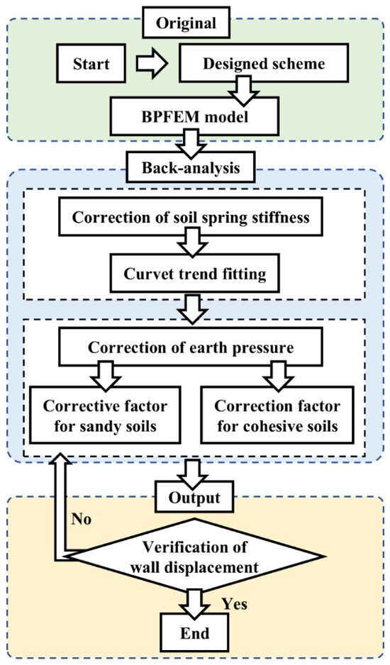
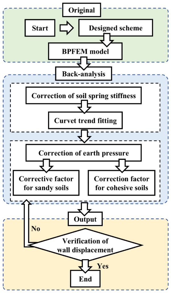
To improve the accuracy and reliability of deformation prediction for retaining systems, a dual-parameter back-analysis method based on the soil horizontal subgrade reaction coefficient (m) and the active earth pressure is adopted in this study to calibrate and optimize soil parameters. In this approach, a BPFEM numerical model is established, and the calculated results are compared with field monitoring data to iteratively perform parameter back-analysis, thereby obtaining soil mechanical parameters that are consistent with actual engineering conditions. The overall procedure, as illustrated in Figure 9, mainly consists of three stages: preliminary analysis, parameter back-analysis, and result validation.
Figure 9.
The back-analysis flow.
In the preliminary analysis stage, a numerical model incorporating both the retaining system and surrounding soil is established based on the designed retaining structure scheme. Using the initial design parameters, the model is employed to compute the excavation-induced deformation of the diaphragm wall and the corresponding internal force distribution under different construction stages.
During the parameter back-analysis stage, the soil horizontal subgrade reaction coefficient (m) for the passive zone, initially derived from the geological investigation report, is first modified. The variation ranges of the back-analysis parameters are determined based on the coefficients of variation in soil properties. A curve-fitting approach is then adopted to align the simulated displacement evolution with the measured deformation trends, enabling a preliminary adjustment of the soil spring stiffness. For the active earth pressure, correction factors are introduced separately for sandy soils and cohesive soils to account for differences in soil properties. Through iterative calibration and fitting, the corrected numerical results are adjusted to better match the field monitoring data, thereby improving the representation of the earth pressure distribution.
Finally, in the validation stage, the horizontal displacement of the retaining structure obtained from the back-analysis model is compared with field measurements. The convergence of the back-analysis is defined using the minimum standard deviation principle. Monitoring points along the diaphragm wall depth are selected, and the calculated wall displacements are compared with field monitoring data. The standard deviation between calculated and measured displacements is adopted as the objective function. The back-analysis is considered converged when the standard deviation reaches its minimum value.
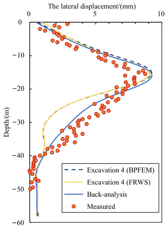
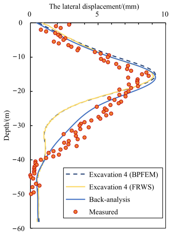
Using the BPFEM program and the proposed soil parameter back-analysis method, a case study is conducted based on cross-section 10 of the Liulitai Metro Station excavation. Soil stratification parameters, structural information, and excavation sequences are input into the program to compute deformation responses for each construction stage. Subsequently, a selected excavation stage is used for parameter back-analysis. The soil horizontal subgrade reaction coefficient (m) is first adjusted to correct the overall trend of the deformation curve, followed by refinement of the earth pressure to match the peak deformation magnitude. As shown in Figure 10, compared with the pre-calibration results, the back-analyzed deformation curve exhibits significantly improved agreement with field measurements, demonstrating the effectiveness of the proposed back-analysis method.
Figure 10.
The back-analysis results.
4.3.2. Deformation Prediction Method
In this section, the excavation deformation for subsequent unexcavated stages is predicted using the soil horizontal subgrade reaction coefficient (m) and the calibrated earth pressure obtained from the preceding soil parameter back-analysis. To evaluate the feasibility and accuracy of the proposed deformation prediction approach, as well as its applicability to the top-down supported deep excavation adopted in the reference project, deformation data from different monitoring locations along the studied section—corresponding to Monitoring Points No. 12 and No. 27—are selected for comparison between predicted results and field measurements.
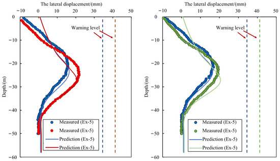
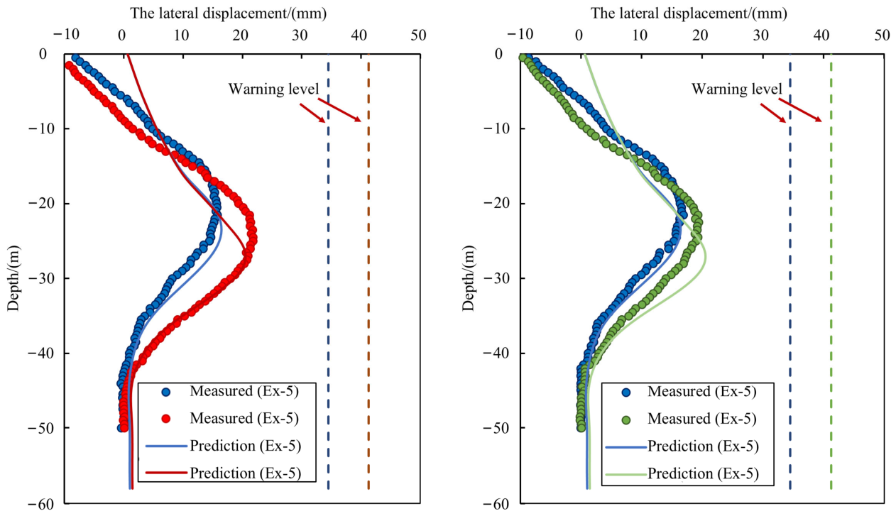
Figure 11 presents the comparison between the predicted deformation curves obtained using the proposed method and the measured data. The high degree of agreement between the curves indicates that the proposed deformation prediction method achieves high accuracy. The predicted retaining structure deformation profile generally matches the field monitoring results, and the error in the predicted maximum deformation is only 4.4%. Therefore, the proposed method is considered reasonable and applicable for predicting the deformation of retaining structures in the top-down deep excavation of the investigated project.
Figure 11.
The comparison between prediction and measured data.
Furthermore, in combination with the latest provisions of the Technical Specification for Retaining and Protection of Building Foundation Excavations [37], a lateral deformation control criterion equal to 0.15% of the excavation depth (Figure 11) is adopted. Based on this criterion, a staged early-warning threshold system corresponding to progressive excavation stages is established, enabling dynamic monitoring and real-time warning throughout the entire construction process of the excavation.
Comparison between the predicted and measured curves in Figure 11 shows that the primary discrepancies are concentrated near the wall top. This deviation is mainly attributed to the application of a relatively large back-propping force during the early excavation stages in the actual project, which was intended to minimize wall deformation. As a result, significant negative displacement at the wall top occurred as early as the third excavation stage, and subsequent excavation had only a minor influence on this displacement, ultimately leading to a relatively large negative wall-top displacement after completion of excavation. The influence of this back-propping force has not yet been incorporated into the numerical framework underlying the proposed deformation prediction method, which represents an important direction for future improvement of the BPFEM computational approach.
5. Conclusions
This study is based on the standard excavation section of the Liulitai Metro Station excavation along Tianjin Metro Line 8. Field monitoring data from six observation points within this section were statistically analyzed to investigate the deformation characteristics of retaining structures in elongated deep excavations constructed in soft soil regions. In addition, a deep excavation deformation analysis program, BPFEM, was developed using the Python (version 3.11.9) programming language, and a deformation prediction method based on soil parameter back-analysis was proposed. The main conclusions are summarized as follows:
- The horizontal deformation of the diaphragm wall exhibits a typical “bulging” profile, with the dominant deformation zone located in the middle–lower portion of the excavation. This region corresponds to the largest earth pressure gradient difference and serves as the primary deformation concentration zone.
- The peak horizontal displacement of the wall increases stepwise with excavation depth. Shallow excavation stages have a limited influence, whereas deformation increases significantly after excavation reaches the second basement level, demonstrating a pronounced depth accumulation effect in deep excavations.
- Significant differences in deformation are observed among monitoring locations. At corner locations, outward tilting at the wall top is smaller than that at central sections, whereas inward bulging in the middle–lower wall is larger. This depth-dependent spatial non-uniformity indicates that the conventional “corner effect” requires re-examination for ultra-deep excavations in soft soils.
- Comparison with results obtained from FRWS 9.0 verifies the accuracy and feasibility of the proposed BPFEM algorithm.
- Application of the proposed soil parameter back-analysis method to the reference project shows reliable back-analysis results, and the calculated wall deformation shows good agreement with field monitoring data.
- The deformation prediction method established based on the soil parameter back-analysis method exhibits high predictive accuracy, with the error in the predicted maximum deformation limited to 4.4%.
Author Contributions
Conceptualization, X.Z., B.L., M.D., Y.M., H.J., M.L. and X.C.; Methodology, C.L. and X.C.; Software, C.L.; Validation, C.L., W.W. and J.L.; Formal analysis, C.L., W.W. and J.L.; Investigation, X.Z., B.L., M.D., Y.M., H.J. and M.L.; Resources, B.L., M.D., H.J., M.L. and X.C.; Data curation, X.Z., C.L. and W.W.; Writing—original draft, C.L., W.W. and J.L.; Writing—review & editing, X.C.; Visualization, C.L. and W.W.; Supervision, X.Z., B.L., M.D., Y.M., H.J., M.L. and X.C.; Project administration, X.Z., B.L., M.D., Y.M., H.J., M.L. and X.C.; Funding acquisition, X.Z., B.L., M.D., Y.M., H.J., M.L. and X.C. All authors have read and agreed to the published version of the manuscript.
Funding
This work was funded by the National Key Research and Development Program of China (No. 2023YFC3009300) and the Tianjin Science Foundation for Distinguished Young Scientists of China (No. 24JCJQJC00170). Their support is gratefully acknowledged.
Data Availability Statement
The original contributions presented in the study are included in the article, further inquiries can be directed to the corresponding author.
Conflicts of Interest
Authors Xinwang Zhang, Bing Li, Mingkang Du, Yongsheng Ma, Hongxue Jia and Meng Liu were employed by the company China Construction Eighth Engineering Division Corp. Ltd. The remaining authors declare that the research was conducted in the absence of any commercial or financial relationships that could be construed as a potential conflict of interest.
References
- Ong, D.E.L.; Chong, E.E.M. Soil–Structure Interactions in a Capped CBP Wall System Triggered by Localized Hydrogeological Drawdown in a Complex Geological Setting. Geosciences 2023, 13, 304. [Google Scholar] [CrossRef] [Scilit]
- Yi, F.; Su, J.; Zheng, G.; Cheng, X.S.; Pei, H.T.; Liu, X.M.; Jia, J.W. Progressive collapse analysis and robustness evaluation of a propped excavation failed due to inappropriate strut removal. Acta Geotech. 2023, 18, 6775–6801. [Google Scholar] [CrossRef] [Scilit]
- Yi, F.; Zheng, G.; Cheng, X.; Huang, T.; Jia, J.; Wang, Z. Progressive collapse analysis of the corner strut subsystem in a propped excavation with inadequate system safety performance. Eng. Fail. Anal. 2024, 160, 108231. [Google Scholar] [CrossRef] [Scilit]
- Li, D.Q.; Zang, H.H.; Tang, X.S.; Rong, G. Efficient Bayesian updating for deformation prediction of high rock slopes induced by excavation with monitoring data. Eng. Geol. 2024, 342, 107772. [Google Scholar] [CrossRef] [Scilit]
- Guo, Z.Z.; Qiu, D.H.; Yu, Y.H.; Xue, Y.G.; Liu, Q.S.; Zhang, W.M.; Li, Z. Analysis and prediction of nonuniform deformation in composite strata during tunnel excavation. Comput. Geotech. 2023, 157, 105338. [Google Scholar] [CrossRef] [Scilit]
- Xia, C.Q.; Chen, X.S.; Xie, S.L.; Lei, C.; Chen, W.; Sun, B. Adjacent ultra-long deep excavation induced deformation of metro station-tunnel system: Mechanism and intelligent prediction. Tunn. Undergr. Space Technol. 2026, 173, 107634. [Google Scholar] [CrossRef] [Scilit]
- Cheng, K.; Xu, R.; Ying, H.; Gan, X.; Zhang, L.; Liu, S. Observed performance of a 30.2 m deep-large basement excavation in Hangzhou soft clay. Tunn. Undergr. Space Technol. 2021, 111, 103872. [Google Scholar] [CrossRef] [Scilit]
- Tan, Y.; Zhu, H.; Peng, F.; Karlsrud, K.; Wei, B. Characterization of semi-top-down excavation for subway station in Shanghai soft ground. Tunn. Undergr. Space Technol. 2017, 68, 244–261. [Google Scholar] [CrossRef] [Scilit]
- Feng, R.-F.; Zhang, Q.-Q.; Liu, S.-W. Experimental Study of the Effect of Excavation on Existing Loaded Piles. J. Geotech. Geoenviron. Eng. 2020, 146, 04020091. [Google Scholar] [CrossRef] [Scilit]
- Liu, G.B.; Jiang, R.J.; Ng, C.W.W.; Hong, Y. Deformation characteristics of a 38 m deep excavation in soft clay. Can. Geotech. J. 2011, 48, 1817–1828. [Google Scholar] [CrossRef] [Scilit]
- Tan, Y.; Li, M. Measured performance of a 26 m deep top-down excavation in downtown Shanghai. Can. Geotech. J. 2011, 48, 704–719. [Google Scholar] [CrossRef] [Scilit]
- Tan, Y.; Wei, B. Observed Behaviors of a Long and Deep Excavation Constructed by Cut-and-Cover Technique in Shanghai Soft Clay. J. Geotech. Geoenviron. Eng. 2012, 138, 69–88. [Google Scholar] [CrossRef] [Scilit]
- Chen, R.P.; Li, Z.C.; Chen, Y.M.; Ou, C.Y.; Hu, Q.; Rao, M. Failure Investigation at a Collapsed Deep Excavation in Very Sensitive Organic Soft Clay. J. Perform. Constr. Facil. 2015, 29, 04014078. [Google Scholar] [CrossRef] [Scilit]
- Tan, Y.; Wei, B.; Zhou, X.; Diao, Y. Lessons Learned from Construction of Shanghai Metro Stations: Importance of Quick Excavation, Prompt Propping, Timely Casting, and Segmented Construction. J. Perform. Constr. Facil. 2015, 29, 04014096. [Google Scholar] [CrossRef] [Scilit]
- Fan, D.; Tan, Y.; Liu, J.; Gong, D. Database of deep excavations for metro stations in thick water-rich sandy strata: Statistical analyses. Tunn. Undergr. Space Technol. 2025, 165, 106890. [Google Scholar] [CrossRef] [Scilit]
- Liu, N.; Pan, J.; Li, M.; Li, Y. Deformation characteristics of an ultra-deep and small-scale rectangular excavation in Hangzhou soft clay. Tunn. Undergr. Space Technol. 2023, 137, 105117. [Google Scholar] [CrossRef] [Scilit]
- Tao, Y.; Chen, K.; Zhu, J.; Gong, X.; Yu, Z. Monitoring Analysis on the Surrounding Deformation of Super Deep Foundation Pit during the Whole Construction Process in Urban Dense Area. Chin. J. Undergr. Space Eng. 2024, 20, 9. [Google Scholar]
- Arslan, E.; Akmaz, E.; Çakır, U.F.; Öztürk, Ö.; Pir, H.; Acartürk, S.; Akça, N.Ç.; Karakuş, Y.; Sert, S. Finite Element Modeling with Sensitivity and Parameter Variation Analysis of a Deep Excavation: From a Case Study. Buildings 2025, 15, 658. [Google Scholar] [CrossRef] [Scilit]
- He, X.; Chen, X.; Su, D.; Liu, C.; Li, Y. A study of corner effects on an irregular excavation near existing tunnels and zoned and staged excavation technique: Numerical modelling and a case history. Tunn. Undergr. Space Technol. 2026, 169, 107290. [Google Scholar] [CrossRef] [Scilit]
- Wu, R.T.; Gu, X.Q.; Gao, G.Y.; Fan, F.; Zhang, K. Analysis of Deep Excavation Deformation of Shanghai Metro Station Using HSS Model. J. Archit. Civ. Eng. 2021, 38, 7. [Google Scholar]
- Zheng, G.; Zhao, J.; Yu, X.; Zhou, H. Calibration of partial factors for tensile strain design in geosynthetic-reinforced and pile-supported embankment. Transp. Geotech. 2025, 52, 101495. [Google Scholar] [CrossRef] [Scilit]
- Li, Z.; Han, M.; Liu, L.; Li, Y.; Yan, S. Corner and partition wall effects on the settlement of a historical building near a supported subway excavation in soft soil. Comput. Geotech. 2020, 128, 103805. [Google Scholar] [CrossRef] [Scilit]
- Geng, X.; Yu, H.S. A large-strain radial consolidation theory for soft clays improved by vertical drains. Geotechnique 2017, 67, 1020–1028. [Google Scholar] [CrossRef] [Scilit]
- Yin, H.; He, C.; Shan, H. Intelligent Settlement Forecasting of Surrounding Buildings During Deep Foundation Pit Excavation Using GWO-VMD-LSTM. Buildings 2025, 15, 3688. [Google Scholar] [CrossRef] [Scilit]
- Yang, Y.; Liao, S.; Teoh, B.K.; Li, Z.; Liu, M.; Chen, L. A physics-constrained neural network for predicting excavation-induced ground surface settlement in clay. J. Rock Mech. Geotech. Eng. 2025, 17, 2665–2681. [Google Scholar] [CrossRef] [Scilit]
- Li, X.; Wu, L.-J.; Wang, Y.-J.; Liu, H.; Chen, Z.-Y.; Jing, L.-J.; Wang, Y. A data driven real-time perception method of rock condition in TBM construction. Can. Geotech. J. 2023, 61, 1018–1034. [Google Scholar] [CrossRef] [Scilit]
- Yang, C.; Zhang, X.-G.; Zhang, G.-H.; Wang, C.; Fan, J.-S. Towards reliable deep excavation monitoring through graph recurrent neural network-based spatio-temporal imputation. Reliab. Eng. Syst. Saf. 2026, 270, 112149. [Google Scholar] [CrossRef] [Scilit]
- Li, Q.; Cheng, F.; Zhang, X. Numerical Simulation and Deformation Prediction of Deep Pit Based on PSO-BP Neural Network Inversion of Soil Parameters. Sensors 2024, 24, 2959. [Google Scholar] [CrossRef] [Scilit]
- Deng, C.; Shen, Y.; Wang, Z.; Li, D. Dynamic forward–inverse prediction of excavations using mobilisable strength design and multi-receptive field convolutional neural network. Reliab. Eng. Syst. Saf. 2026, 274, 112454. [Google Scholar] [CrossRef] [Scilit]
- Zhao, C.; Chen, L.; Ni, P.; Xia, W.; Wang, B. A modified back analysis method for deep excavation with multi-objective optimization procedure. J. Rock Mech. Geotech. Eng. 2024, 16, 1373–1387. [Google Scholar] [CrossRef] [Scilit]
- Jong, S.C.; Ong, D.E.L. A novel Bayesian network approach for predicting soil-structure interactions induced by deep excavations. Tunn. Undergr. Space Technol. 2024, 152, 105865. [Google Scholar] [CrossRef] [Scilit]
- Tao, Y.; Sun, H.; Cai, Y. Predictions of Deep Excavation Responses Considering Model Uncertainty: Integrating BiLSTM Neural Networks with Bayesian Updating. Int. J. Geomech. 2022, 22, 04021250. [Google Scholar] [CrossRef] [Scilit]
- Aljanabi, K.R.; Al-Azzawi, O.M. Neural network application in forecasting maximum wall deflection in homogenous clay. Int. J. Geo-Eng. 2021, 12, 29. [Google Scholar] [CrossRef] [Scilit]
- Jiang, F.; Dong, S. Development of a CNN-based integrated surrogate model in evaluating the damage of buried pipeline under impact loads, considering the soil spatial variability. Reliab. Eng. Syst. Saf. 2025, 257, 110801. [Google Scholar] [CrossRef] [Scilit]
- Yang, J.; Liu, Y.; Yagiz, S.; Laouafa, F. An intelligent procedure for updating deformation prediction of braced excavation in clay using gated recurrent unit neural networks. J. Rock Mech. Geotech. Eng. 2021, 13, 1485–1499. [Google Scholar] [CrossRef] [Scilit]
- Bouhacina, O.; Khatir, A.; Matoug, S.A.; Tamine, T. A Novel Hybrid TOARS-Optimized Ensemble of Tree-Based Models for Predicting Soil Temperature at Shallow Depths. Sustainability 2026, 18, 294. [Google Scholar] [CrossRef] [Scilit]
- JGJ120-2012; Technical Specification for Retaining and Protection of Building Foundation Excavations. China Architecture & Building Press: Beijing, China, 2012.
- Pan, Y.; Li, X.; Qin, J.; Chen, J.-J.; Gardoni, P. Towards trustworthy excavation-induced risk warning for adjacent building: A Bayesian reasoning based probabilistic deep learning method. Undergr. Space 2025, 25, 156–175. [Google Scholar] [CrossRef] [Scilit]
- Wu, Y.; Xue, D.; Chen, K.; Dai, C.; Hang, Z.; Wu, Z.; Zhang, S. Failure mechanism and early warning of an excavation-induced soil landslide. Front. Earth Sci. 2024, 12, 1410011. [Google Scholar] [CrossRef] [Scilit]

Disclaimer/Publisher’s Note: The statements, opinions and data contained in all publications are solely those of the individual author(s) and contributor(s) and not of MDPI and/or the editor(s). MDPI and/or the editor(s) disclaim responsibility for any injury to people or property resulting from any ideas, methods, instructions or products referred to in the content. |
© 2026 by the authors. Licensee MDPI, Basel, Switzerland. This article is an open access article distributed under the terms and conditions of the Creative Commons Attribution (CC BY) license.