


Abstract
Dehumidification plays a vital role across industrial, commercial, and residential settings, where controlling moisture is essential for maintaining air quality, protecting materials, and ensuring comfort. Calcium chloride (CaCl2) is a widely used, low-cost desiccant, but it suffers from a critical drawback: under humid conditions, particles tend to agglomerate, which reduces their ability to absorb water. In addition, when the salt dissolves in hydration water, its contact surface with moist air decreases, and corrosive liquid leakage can occur. Embedding CaCl2 into hydrophilic porous matrices offers a solution by dispersing particles more effectively, preventing agglomeration, increasing the contact area, and retaining liquid within the pore network to suppress leakage. In this study, we introduce a novel approach for fabricating carbon-based foams impregnated with CaCl2, produced through the thermal decomposition of glucose under self-induced pressure. These foams exhibit a composite architecture that integrates CaCl2 and calcium carbonate, enabling controlled porosity through selective dissolution. Importantly, the in situ transformation of CaCl2 into calcite refines the internal structure, improving both stability and acids absorption performance. FTIR confirmed the strong hydrophilicity of the foam walls, which enhances water vapor uptake while preventing leakage of saturated salt solutions. The carbon matrix further suppresses salt particle agglomeration during moisture absorption, resulting in high efficiency. These multifunctional foams not only capture water vapor and volatile acids but also show potential as phase change materials. Mechanical testing revealed tunable behavior among the fabricated foams, ranging from high-stiffness structures with superior energy absorption (e.g., C2) to more compliant foams with extended strain capacity (e.g., A2), illustrating their versatility for practical applications.
1. Introduction
Aerogels are among the most intriguing types of porous materials. They combine extreme lightness with impressive structural and functional traits. These materials are produced when the liquid part of a gel is replaced by gas, keeping the fragile solid structure intact. This process leads to solids that often have porosities above 90 to 99.8%. The first mention of silica aerogels comes from S.S Kistler in 1931, who showed that removing liquid under supercritical conditions could stop pore collapse and maintain a highly porous structure [1]. Since that time, researchers have made aerogels from many inorganic and organic sources, including silica [2] alumina, titania [3], polymers [4], carbon [5], as well as hybrid materials [6,7]. Their low thermal conductivity, high porosity, and adjustable chemistry have sparked interest in areas like insulation, energy storage [8], catalysis [9], and environmental cleanup [10].
Aerogels’ unique properties come from their hierarchical pore structure and very large internal surface area. Depending on the precursor and method used, pore sizes can be classified as micro- (less than 2 nm), meso- (2 to 50 nm), or macro- (over 50 nm). The mix of these pore types affects both the material’s adsorption capacity and transport behavior. Foams represent a distinct class of porous materials, characterized by significantly larger pore sizes and thicker cell walls [11]. In certain cases, the cell walls may incorporate aerogel, provided a continuous 3D meso- or microporous structure is present. Unlike aerogels, foams can exhibit either closed or open porosity, with each type serving different application domains. Impregnation of highly porous materials with hygroscopic substances acts on increasing their capacity to retain water vapor, making them particularly useful in construction applications. Carbon foams are generally biodegradable and exhibit low toxicity; however, the precursors employed in their synthesis are typically synthetic chemicals [12]. Furthermore, the production process often involves costly equipment and high energy consumption. Impregnation is usually performed in a secondary stage after the carbon matrix has been formed, although a one-step synthesis would be preferable.
Carbon-based porous masses are generally obtainable from more cost-effective precursors compared to other types of aerogels. They are typically made through sol–gel polymerization of resorcinol-formaldehyde or other organic materials, followed by drying and pyrolysis in inert conditions [8,13]. This process turns the organic gel into a conductive carbon network while keeping the open porous structure. Additional activation steps, like treating with KOH or CO2, can further increase the surface area; however, the KOH activation method is not yet fully understood. Some authors suggest that metallic potassium forms within the carbon structure at temperatures below 500 °C, through the reduction of potassium ions by carbon [14]. However, this mechanism appears unlikely, as no potassium vapor has been detected in the system. Natural carbon sources such as anthracite contain non-negligible amounts of ash, and the transition metals present are likely reduced by carbon prior to potassium. This sequence may influence the activation process by promoting carbon oxidation and leading to the formation of K2CO3 as a secondary reaction product. The water present in the system originates primarily from the thermal decomposition of KOH [15]. These traits make carbon aerogels suitable for electrochemical applications, including electrodes for supercapacitors, lithium-ion batteries, and electrocatalytic devices [16,17]. For instance, carbon aerogels used as supercapacitor electrodes can provide high specific capacitances due to their large surface area for charge storage and hierarchical pores that help with ion transport [17,18].
Besides energy storage, carbon aerogels are also useful as catalyst supports because of their high conductivity and adjustable surface chemistry [18]. They create a stable structure for dispersing nanoparticles such as platinum, iron oxide, or cobalt catalysts, improving performance in fuel cells, Fischer–Tropsch synthesis, or environmental catalysis [19]. Their excellent ability to adsorb makes them promising materials for capturing greenhouse gases like CO2, volatile organic compounds, and heavy metals from water solutions [20,21]. Their thermal stability and lightweight nature also enable uses in thermal insulation, sound damping, and electromagnetic shielding [22].
Recently, the focus has shifted to more sustainable methods for producing aerogels, particularly those made from biomass. Renewable sources, such as cellulose, starch, lignin, and glucose, can be converted into highly porous gels that yield biopolymer aerogels upon drying [23]. When subjected to pyrolysis, these biopolymer aerogels turn into carbon aerogels or foams, providing an eco-friendly alternative to polymers made from petroleum [24]. Glucose, in particular, is a flexible building block because it can undergo hydrothermal carbonization or polymerization to create gels that can be freeze-dried into aerogels with open structures [25]. After carbonization, glucose-derived aerogels maintain much of their porosity and develop conductive carbon structures [26]. These bio-based aerogels not only reduce environmental impact but also offer unique pore architectures and surface properties due to their natural structure [27].
Several methods have been shown to convert glucose into carbon aerogels or foams. In hydrothermal synthesis, concentrated glucose solutions are heated under pressure, leading to polymerization and dehydration reactions that produce hydrothermal carbons. Following drying and pyrolysis, this results in carbon-rich networks with hierarchical porosity [28]. Other methods mix glucose with crosslinkers to form hydrogels, which can produce ultralight aerogels after freeze-drying. Carbonizing these structures at high temperatures leads to lightweight carbon foams with specific surface areas suitable for adsorption and energy storage [29]. Using glucose and other biomass-derived sources gives a promising route to sustainable aerogels that match the humidity properties of those made from synthetic sources [30].
A key application area for both synthetic and bio-derived foams is removing moisture and chemical pollutants. Their high surface area and open-pore structure allow for efficient uptake of water vapor, volatile organics, and ions. Moisture adsorption is important for humidity control, water harvesting, and dehumidification technologies. Dehumidification plays a critical role in maintaining air quality, protecting sensitive materials, and ensuring comfort across industrial, commercial, and residential environments. Conventional moisture-absorbing materials often suffer from limited capacity, poor mechanical integrity, or leakage during saturation, prompting the need for multifunctional alternatives with enhanced performance and structural control.
Carbon-based foams have emerged as promising candidates due to their lightweight architecture, high surface area, and chemical tenability. However, most existing synthesis routes involve multi-step procedures or lack control over pore morphology and functional integration. In this context, one-pot synthesis strategies offer a streamlined pathway to engineer composite foams with tailored properties, enabling simultaneous control over porosity, chemical functionality, and mechanical behavior. For example, foams treated with hygroscopic salts or polar groups can absorb water up to several times their own weight and can be regenerated through mild heating or solar exposure [31]. These systems are promising for collecting atmospheric water in dry areas. Additionally, foams have been studied as desiccants in packaging, electronics protection, and controlled environments where moisture management is essential [32]. This study introduces a novel one-pot approach for fabricating carbon-based composite foams via the thermal decomposition of glucose under self-induced pressure. The incorporation of calcium chloride (CaCl2) and calcium carbonate (CaCO3) into the carbon matrix allows for selective dissolution and in situ transformation into calcite, yielding a hierarchically porous structure with enhanced moisture and volatile acid capture capabilities. The resulting foams exhibit strong hydrophilicity, phase change material (PCM) behavior, and tunable mechanical properties, making them suitable for a wide range of environmental and energy-related applications.
Foams also work effectively to absorb chemical pollutants. Activated carbon foams can capture significant amounts of CO2 due to their micropore structure and surface chemistry [33]. Additionally, they have been shown to remove dyes, heavy metals, and organic solvents from water, making them valuable for treating wastewater [34]. Their adsorption works through both physical filling of pores and chemical interactions with functional groups on the aerogel surface. Compared to traditional activated carbons, foams provide a tunable and interconnected pore network that can improve diffusion rates and adsorption kinetics [35].
These findings show that foams are a versatile material platform, linking fundamental science with practical technologies. Carbon foams, whether made from synthetic polymers or renewable glucose, demonstrate the potential of combining lightweight design with electrical conductivity and environmental friendliness. Ongoing development is likely to boost progress in energy storage, catalysis, pollutant capture, and water harvesting. However, challenges remain in scaling production, ensuring mechanical durability, and optimizing cost-performance balance. Still, the unique combination of properties makes foams essential candidates for creating next-generation functional materials [36].
Porous carbon-based materials have attracted significant attention due to their versatility in energy storage, thermal insulation, and environmental control. Within this broad class, composite foams derived from carbohydrate precursors offer a sustainable route to functional materials with tunable porosity and mechanical resilience. Recent advances (2024–2025) have highlighted the growing role of carbon-based aerogels and foams in sustainable construction. Novel aerogel composites have been developed for building insulation with high thermal performance [37], while circular initiatives such as CARBIP [38] emphasize eco-friendly, reusable insulation systems. Reviews of aerogel insulation for exterior walls [39] and studies on low-carbon architecture [40] further underline their relevance in passive climate regulation and energy-efficient building design. These developments provide a timely context for our investigation of glucose–CaCl2-derived foams as potential building materials.
In this study, we present a simple and affordable way to create carbon-based foams, produced by the thermal decomposition of glucose under its own pressure. What makes these foams special is not only the elegance of their synthesis, but also the possibilities they open up. By introducing a sacrificial calcium salt, we can guide the formation of pores in a controlled manner and later dissolve the salt to fine-tune the structure. This gives us a material that is lightweight, customizable, and surprisingly versatile. Even more intriguing is the in situ transformation of the calcium salt into calcite, achieved through a gentle vapor treatment with ammonia and carbon dioxide. This step adds a mineral backbone to the foam, strengthening it and enhancing its resistance to heat and chemical stress capable of standing up to the demanding conditions of modern buildings. The porous carbon framework acts like a natural shield against heat transfer, making these foams excellent candidates for thermal insulation. Their ability to trap air in the pores reduces energy loss, while their stability across a wide temperature range ensures reliable performance in both hot summers and cold winters. At the same time, the foams interact with water vapor and gases in a way that helps regulate moisture indoors, preventing condensation and improving air quality. This multifunctionality means they are more than just insulators—they are active participants in creating healthier, more sustainable living spaces.
2. Materials and Methods
2.1. Synthesis of Carbon-Based Foams
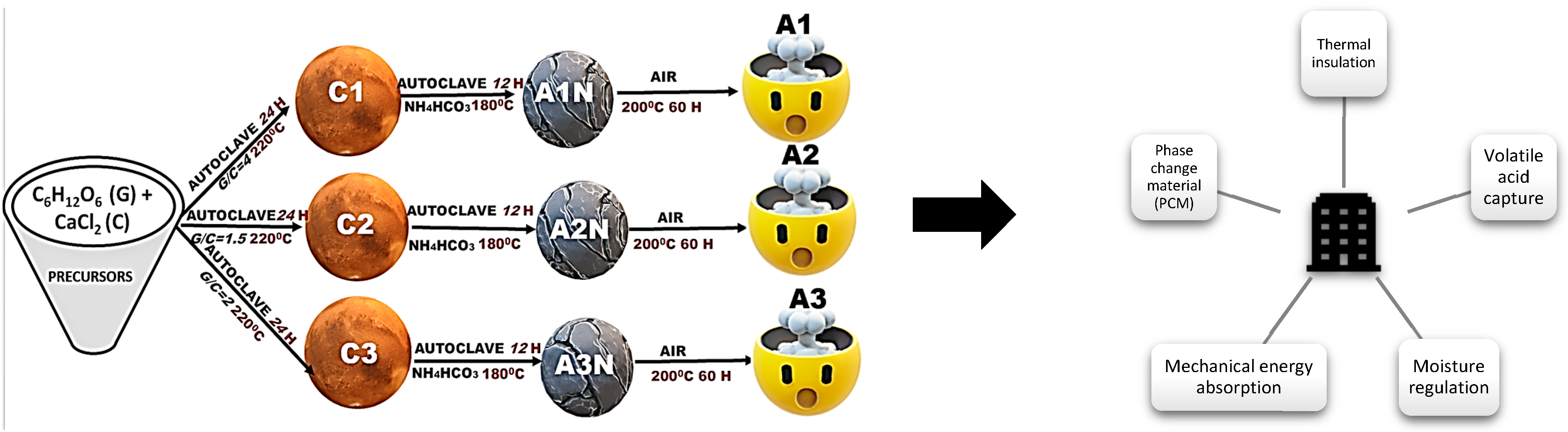
Anhydrous glucose (G) and calcium chloride (C) were mixed at mass ratios 4:1 (C1), 3:2 (C2), and 3.33:1.66 (C3). The mixtures were transferred into Berzelius beakers placed at the bottom of 100 mL Teflon-lined stainless-steel autoclave vessels. The autoclaves were sealed and heated at 220 °C for 24 h. Calcium chlorine anhydrous was procured from Sigma Aldrich and NH4CO3 were obtained from Reactivul Bucuresti. Glucose (C6H12O6) was procured from SC Chimreactiv SRL (Bucharest, Romania).
After cooling, the resulting carbonaceous foams were extracted and cut into cylindrical specimens with a diameter of 18 ± 0.2 mm and a height of 5 ± 0.3 mm using a CNC system.
Calcite Loading Procedure
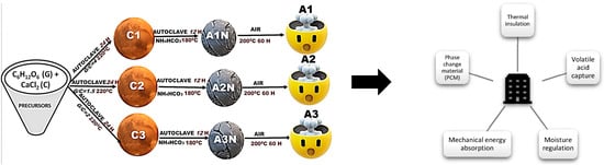
Foam specimens were subjected to a secondary vapor-phase treatment in an atmosphere containing CO2, NH3, and H2O. These vapors were generated in situ by the thermal decomposition of 58 mg of ammonium bicarbonate (NH4HCO3) placed inside the autoclave, ensuring no direct contact with the samples. The treatment was conducted at 180 °C for 12 h. Subsequently, the samples were heated in air at 200 °C for 60 h to sublimate residual byproducts formed during the in situ conversion of CaCl2 to CaCO3 (calcite). For clarity, the overall experimental workflow is summarized in Figure 1, which outlines the synthesis, treatment, and characterization steps in a sequential manner.
Figure 1.
Workflow representation of sample synthesis.
2.2. Physico-Chemical Characterization
X-ray diffraction (XRD) was performed using an X’Pert PRO MPD diffractometer (PANalytical, Almelo, The Netherlands) with Ni-filtered Cu Kα radiation (λ = 1.54 Å).
Fourier-transform infrared (FTIR) spectroscopy was conducted on a Vertex 70 instrument (Bruker, Ettlingen, Germany).
Scanning electron microscopy (SEM) was recorded with FIB-SEM, Zeiss Auriga. Thermogravimetric analysis (TGA) was performed in air using a TG 209F1 Libra instrument (Netzsch, Selb, Germany).
Ammonium ion concentrations were measured colorimetrically using a Hanna Instruments HI700 Digital Absorption Photometer Checker HC (Ammonia Nitrogen LR, Fresh Water, Smithfield, RI, USA), with a detection range of 0.00–3.00 ppm (mg/L), a resolution of ±0.05 ppm, and an accuracy of ±5% at 25 °C.
Acid Vapor Adsorption via FTIR Gas Cell Tests
The foam’s capacity to retain volatile acids was evaluated using quantitative FTIR spectrometry. Acetic acid vapors were introduced into a sealed gas cell (path length: 100 mm; internal diameter: 40 mm; volume: 125 cm3) fitted with KCl windows. One window was modified to accommodate a PTFE-based dosing device that released a defined foam mass directly into the cell.
To prevent water vapor condensation during gas recirculation, the acetic acid solution was cooled in an ice bath, and aerosols were removed using a 0.2 µm polyethersulfone syringe filter (30 mm diameter). This setup generated acetic acid vapors with a calculated partial pressure of 0.58 mmHg.
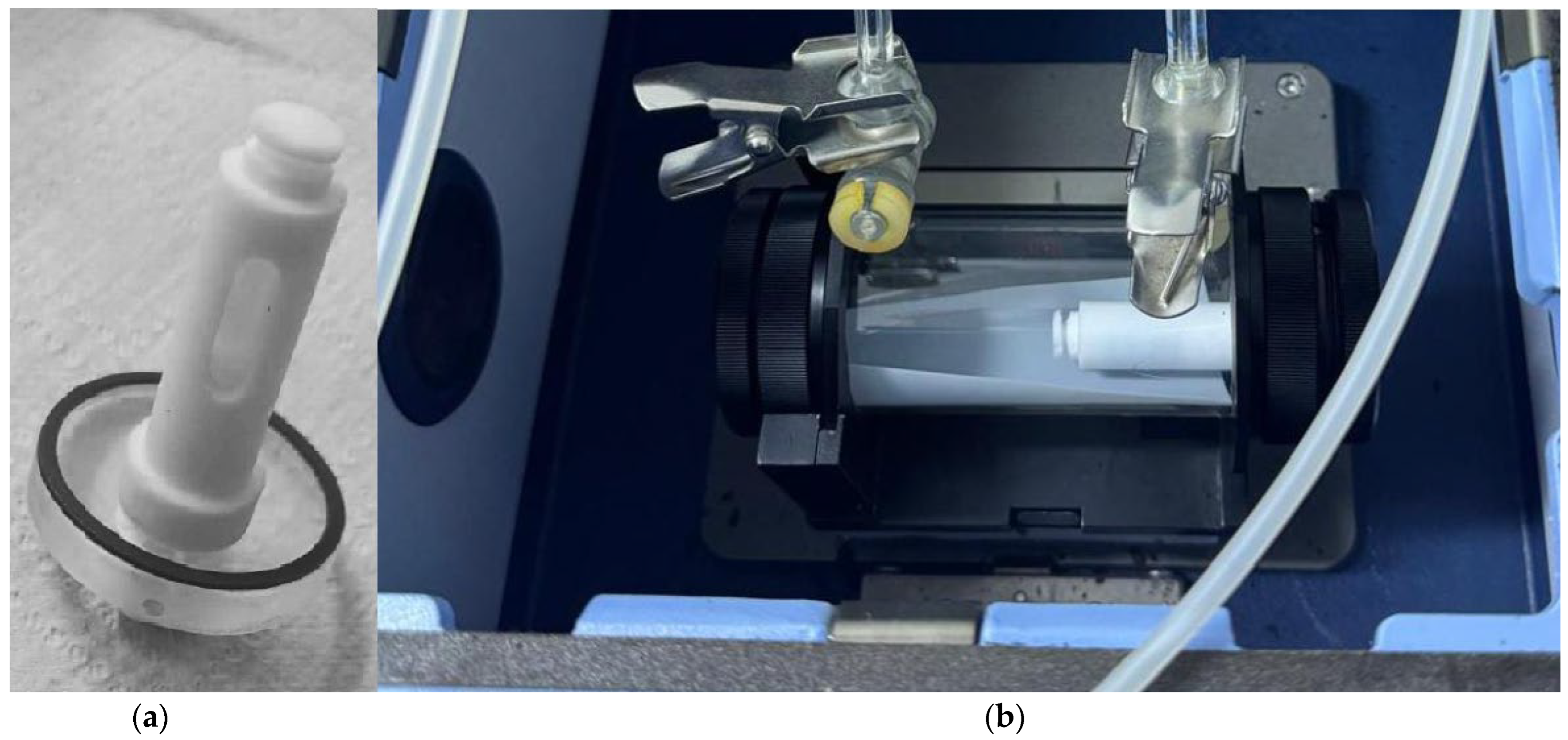
The gas was recirculated using a diaphragm-type micropump for 20 min. After sealing the system, 80 mg of foam was introduced, and FTIR spectra were recorded every 300 s over a 65 min period. The experimental setup is illustrated in Figure A1 (Appendix A). This ability of the foams to capture volatile acids will be further explored as a functional property, with the perspective of integrating such materials into building applications where they could contribute to improved indoor air quality and enhanced protection of structural elements.
2.3. Mechanical Characterization
Foam specimens (18 ± 0.2 mm diameter, 5 ± 0.3 mm height) were subjected to uniaxial compression testing using a Metrotec universal testing system. All tests were conducted at room temperature under displacement control, with a constant crosshead speed of 2 mm/min.
Force-displacement data were converted into engineering stress–strain curves using the measured specimen dimensions. These curves were used to extract relevant mechanical parameters, including stiffness, strength, and energy absorption (EA) capacity.
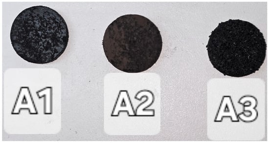
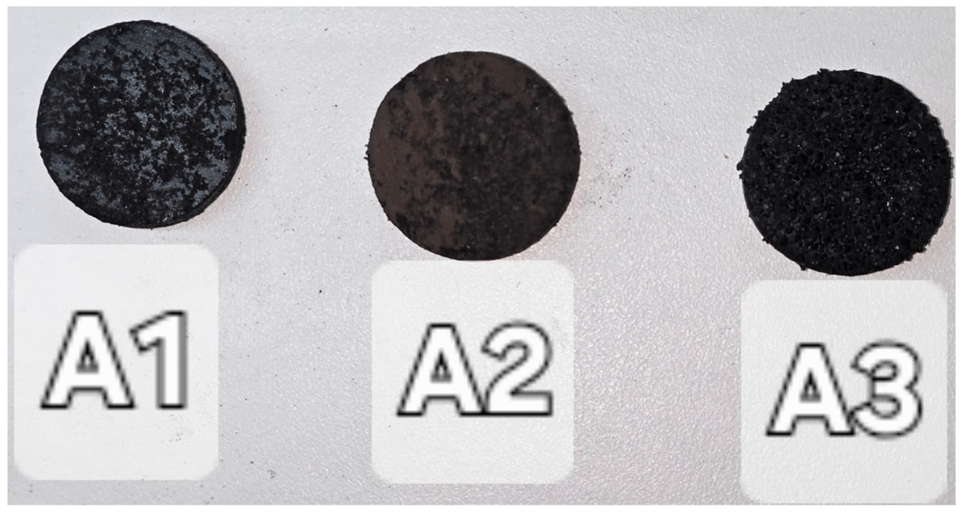
Following the initial thermal treatment and subsequent cooling, the resulting carbonaceous foams were extracted. Cylindrical specimens with a diameter of 18 ± 0.2 mm and a height of 5 ± 0.3 mm were cut from the foams using a CNC machine as in Figure 2.
Figure 2.
Cylindrical Foam Specimens Prepared for Experimental where A1–A3 are described in Figure 1.
3. Results and Discussions
3.1. X-Ray Diffraction
Upon heating the glucose–CaCl2 mixture to approximately 150 °C, glucose begins to melt and dissolves anhydrous CaCl2, forming eutectic mixtures with reduced viscosity at specific molar ratios. As the temperature increases, reaction (1) is promoted, leading to the formation of 5-hydroxymethylfurfural (HMF) through a three-step dehydration of glucose:
C6H12O6 → C6H6O3 + 3H2O.
CaCl2 plays a dual role in this process: it lowers water activity, promoting dehydration, and acts as a Lewis acid catalyst, facilitating glucose isomerization to fructose—a known precursor to HMF. The resulting HMF undergoes polymerization and carbonization, especially under prolonged heating, increasing the viscosity of the reaction medium.
The hygroscopic nature of CaCl2 further reduces water vapor pressure, forming crystal hydrates that melt below 200 °C. This molten phase enhances polymer chain mobility and stabilizes gas bubbles, preventing premature coalescence. When internal pore pressure equilibrates with the vapor pressure above the foam, expansion ceases. Experimental observations show that decreasing the glucose to CaCl2 mass ratio from 4 to 1.5 leads to significantly more expanded structures with increased porosity. In the absence of CaCl2, gas bubbles coalesce and escape, resulting in less uniform pore distribution.
Foams with smaller, closed-cell pores exhibit greater structural integrity and reduced gas diffusion, which is advantageous for achieving high internal surface area and low thermal conductivity. Smaller bubbles withstand higher pressures, and closed-cell foams formed by such bubbles possess more cell walls, limiting long-range gas diffusion. Therefore, controlling reactor pressure is key to regulating foam porosity.
During hydrothermal treatment, glucose undergoes a sequence of dehydration, isomerization, and polymerization steps that are strongly influenced by the presence of CaCl2. Calcium ions can coordinate with hydroxyl groups of glucose and intermediate species, promoting local cross-linking and stabilizing partially dehydrated structures. This coordination lowers the activation energy for dehydration and accelerates the formation of oligomers and carbon-rich nuclei. In parallel, chloride ions do not catalyze the decomposition of glucose into 5-hydroxymethylfurfural (HMF), but they enhance both the selectivity and the rate of fructose conversion to this intermediate compound [41].
The isomerization of glucose to fructose can be readily catalyzed by the mildly acidic environment generated through salt hydrolysis; however, the salt does not act as a specific or selective catalyst. By lowering the water activity in the system and through the complexing effect of the cation, CaCl2 stabilizes the 1,2-enediol intermediate, which plays a decisive role in the isomerization process.
In study Zhi-Xiang Xu and co-authors [42] investigated biocarbon production Via hydrothermal synthesis in the presence of metal salts at moderate concentrations (~10%). They reported that the carbon yield increased in the presence of such salts, which were partially adsorbed onto the carbon surface. Xue-Qin Ma [43] likewise observed that NaCl promoted hydrolysis, dehydration, and decarboxylation. Process yield was also strongly temperature-dependent, with a maximum at 220 °C, followed by a decline at higher temperatures, most likely due to hydrolytic degradation of polymer chains at elevated temperatures.
In our study, the concentration of CaCl2 was substantially higher (20–40%), and thus the expected catalytic and structural effects are correspondingly amplified. This higher salt loading not only accelerates glucose conversion but also enhances the stabilization of intermediate carbonaceous structures, leading to improved foam formation and more pronounced porosity control compared to the moderate salt concentrations reported in the literature.
Following carbonization, the foams consist of compact cellular carbon structures and carbon–CaCl2 composites. Due to CaCl2’s high solubility, water or saturated steam treatment can open pores in the walls containing solid CaCl2. However, in larger samples, water diffusion is limited, and the formation of a saturated CaCl2 solution within pores can inhibit further dissolution. As shown in Figure A2 (Appendix A), pore opening after water washing is clearly visible, confirming that foams with tunable porosity—either closed or open—can be obtained depending on the applied treatment. During subsequent heating of the foams in NH4HCO3 vapor, reaction (2) initiates the thermal decomposition of ammonium carbonate, yielding NH3, H2O, and CO2; These gaseous products then react with CaCl2 embedded in the foam matrix, leading to the in situ formation of calcite (CaCO3) and ammonium chloride (NH4Cl) via reaction (3).
(NH4)2CO3 → 2 NH3 + H2O + CO2
CaCl2 + CO2 + 2 NH3 + H2O → CaCO3 + 2 NH4Cl
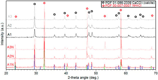
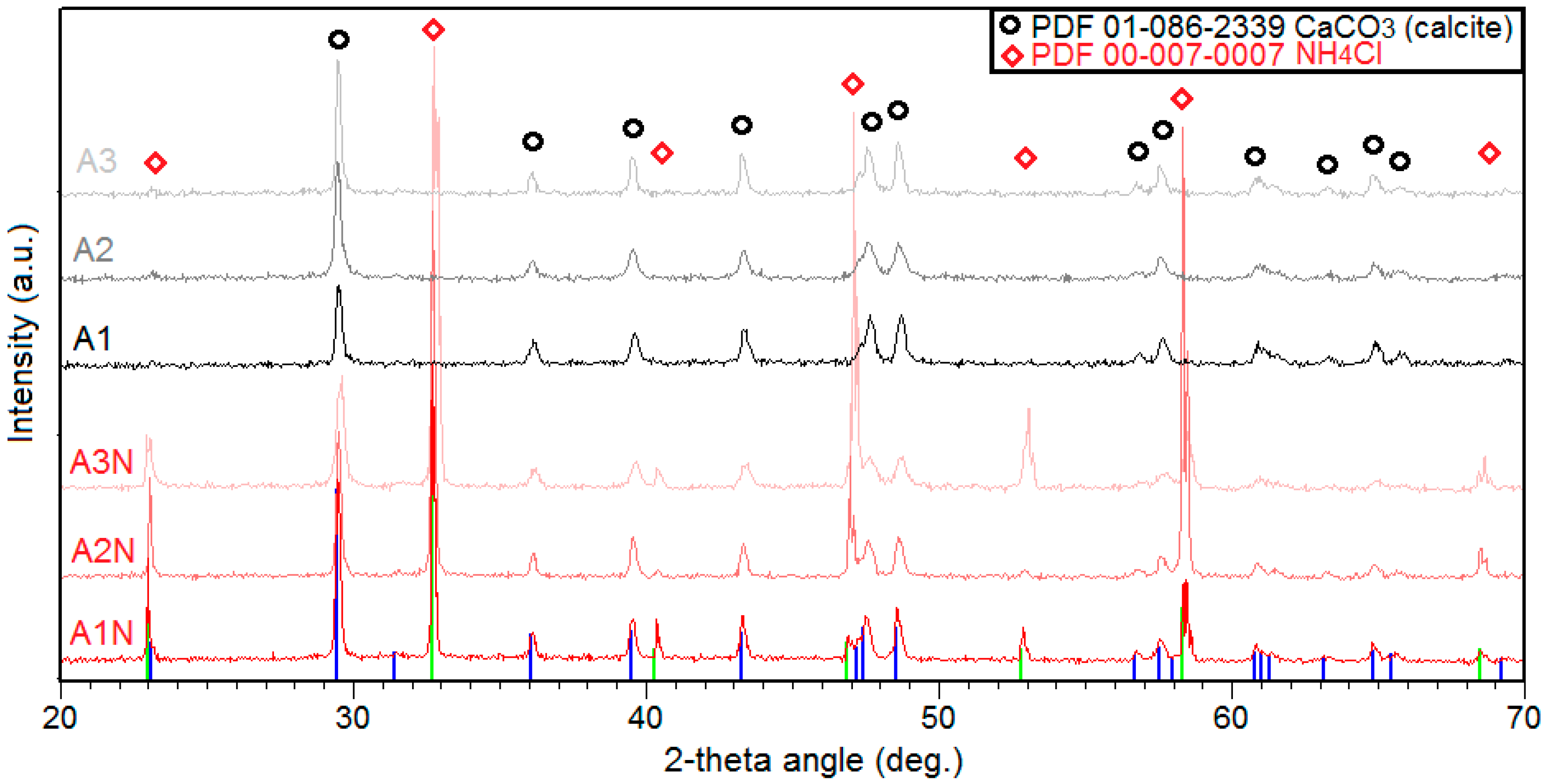
As observed in the XRD patterns shown in Figure 3, samples A1N–A3N contain both calcite and NH4Cl, as expected according to reaction (3). To remove this phase from the system, the samples were subjected to thermal treatment for 60 h at 200 °C, as described in the experimental section. At this temperature, the vapor pressure of NH4Cl is approximately 1 mmHg, sufficiently high to enable complete sublimation of this crystalline phase. Consequently, the XRD spectra of samples A1–A3 no longer exhibit the NH4Cl phase. At 200 °C, the vapor pressure of NH4Cl is approximately 1.0 mmHg, which is sufficiently high to enable complete sublimation of the crystalline phase from the foam matrix. This value aligns with literature data from Tomida et al. (2008) [44], who measured vapor pressures of NH4Cl–NH3 mixtures and reported values consistent with this range at elevated temperatures. Their work provides a reliable basis for interpreting sublimation behavior under your experimental conditions. The XRD analysis confirming the coexistence of carbon phases and in situ formed calcite further supports the potential of these foams to be adapted as building materials, since the mineral reinforcement combined with the porous carbon matrix can provide both mechanical stability and enhanced thermal insulation properties.
Figure 3.
XRD comparison of ammonia-treated (A1N–A3N; the curves are displayed in shades of red) and thermally purified (A1–A3; the curves are plotted in different shades of gray) foams.
This complete sublimation can only occur if the foams exhibit open porosity, which enables pressure equalization between the internal pore network and the external atmosphere, as well as the diffusion of volatile species such as NH3 and HCl. This structural feature is fundamentally distinct from the closed porosity required during the formation of C/CaCl2-based foams. In those systems, closed-cell architecture is essential to sustain foam expansion; without it, the structure would collapse under the influence of surface tension forces acting on the liquid phase. Thus, the porosity type not only governs the foam’s mechanical integrity during synthesis but also determines its suitability for post-synthetic treatments such as sublimation or gas-phase conversion.
3.2. Compressive Behavior and Mechanical Performance
Before testing, all samples were dried at 220 °C for 48 h to remove absorbed moisture, given the high hygroscopicity of calcium chloride. This thermal conditioning ensured stable and reproducible mechanical measurements by preventing variations in stiffness associated with residual water. After drying, the specimens were stored in airtight containers until testing to avoid moisture reabsorption.
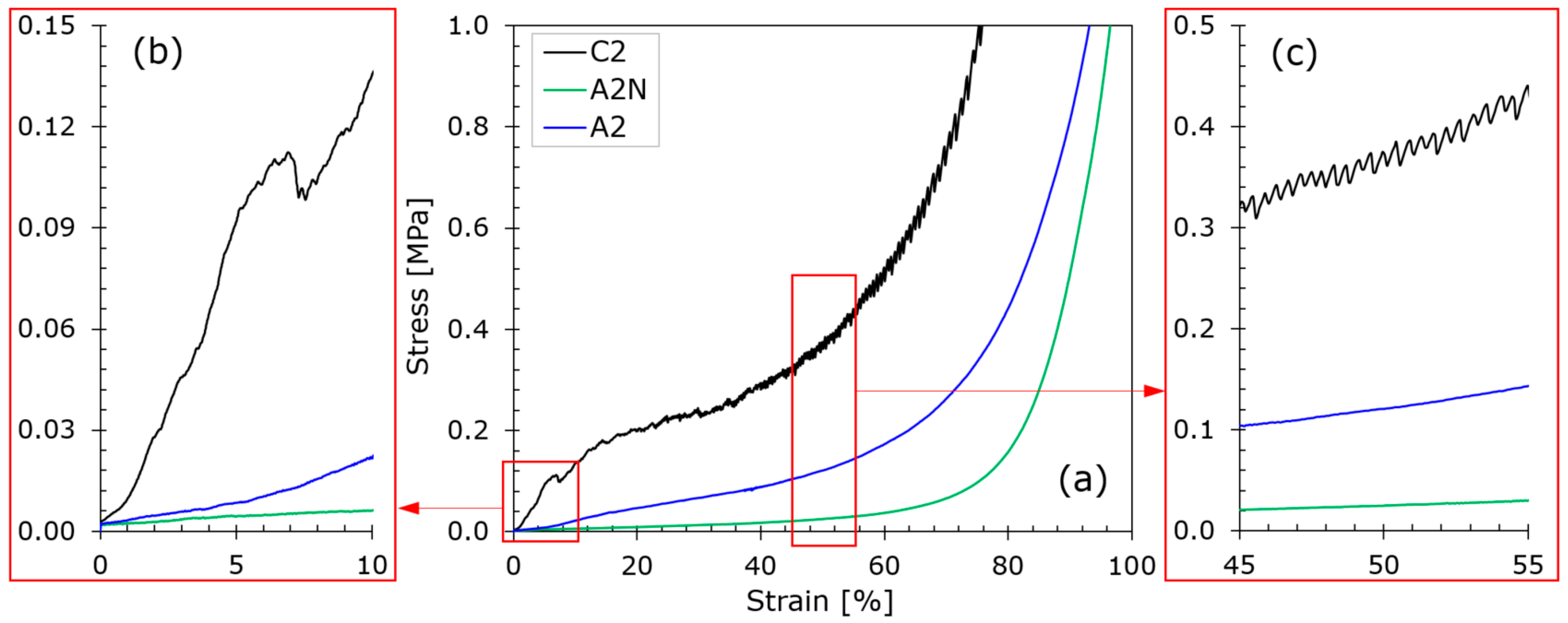
The compressive stress–strain responses of the investigated carbon-based composite foams are presented in Figure 4a, accompanied by magnified views of the initial elastic region (Figure 4b) and the plateau region (Figure 4c). All samples follow the characteristic deformation sequence of cellular solids, consisting of an initial linear elastic regime, a plateau region governed by the progressive collapse of the cellular structure, and a final densification stage marked by a rapid increase in stress with strain [45,46,47]. Despite this shared deformation pattern, the detailed shapes of the curves differ markedly among the foams, reflecting variations in composition and processing history.
Figure 4.
Compressive stress–strain curves (a), with magnified views of the elastic (b) and plateau (c) regimes.
In the elastic regime (Figure 4b), foam C2 exhibits the steepest slope among the three materials, confirming its higher stiffness relative to A2 and A2N. The latter two samples display a more gradual elastic response, consistent with their lower measured moduli. In the plateau region (Figure 4c), foam C2 shows a serrated stress–strain profile with noticeable fluctuations, whereas A2 and A2N present smooth and nearly monotonic plateaus. These differences illustrate the more stable and uniform deformation behavior of the A-series foams during progressive collapse. The densification stage also varies between the formulations. Foam A2 reaches densification at the highest strain level, reflecting its ability to accommodate large deformations before pore compaction. Foam C2 densifies at intermediate strains, whereas A2N exhibits the earliest densification, consistent with its substantially reduced stiffness. Overall, the mechanical responses separate the foams into two behavioral groups: C2, characterized by higher stiffness and fluctuating plateau stress, and A2/A2N, which exhibit lower stiffness and more stable plateau regions. These differences highlight the strong influence of composition and thermal treatment on stiffness, plateau stability, and strain capacity; parameters essential for predictable compressive behavior and reliable deformation performance.
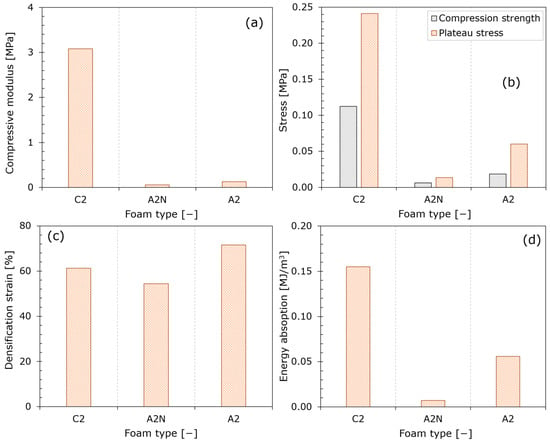
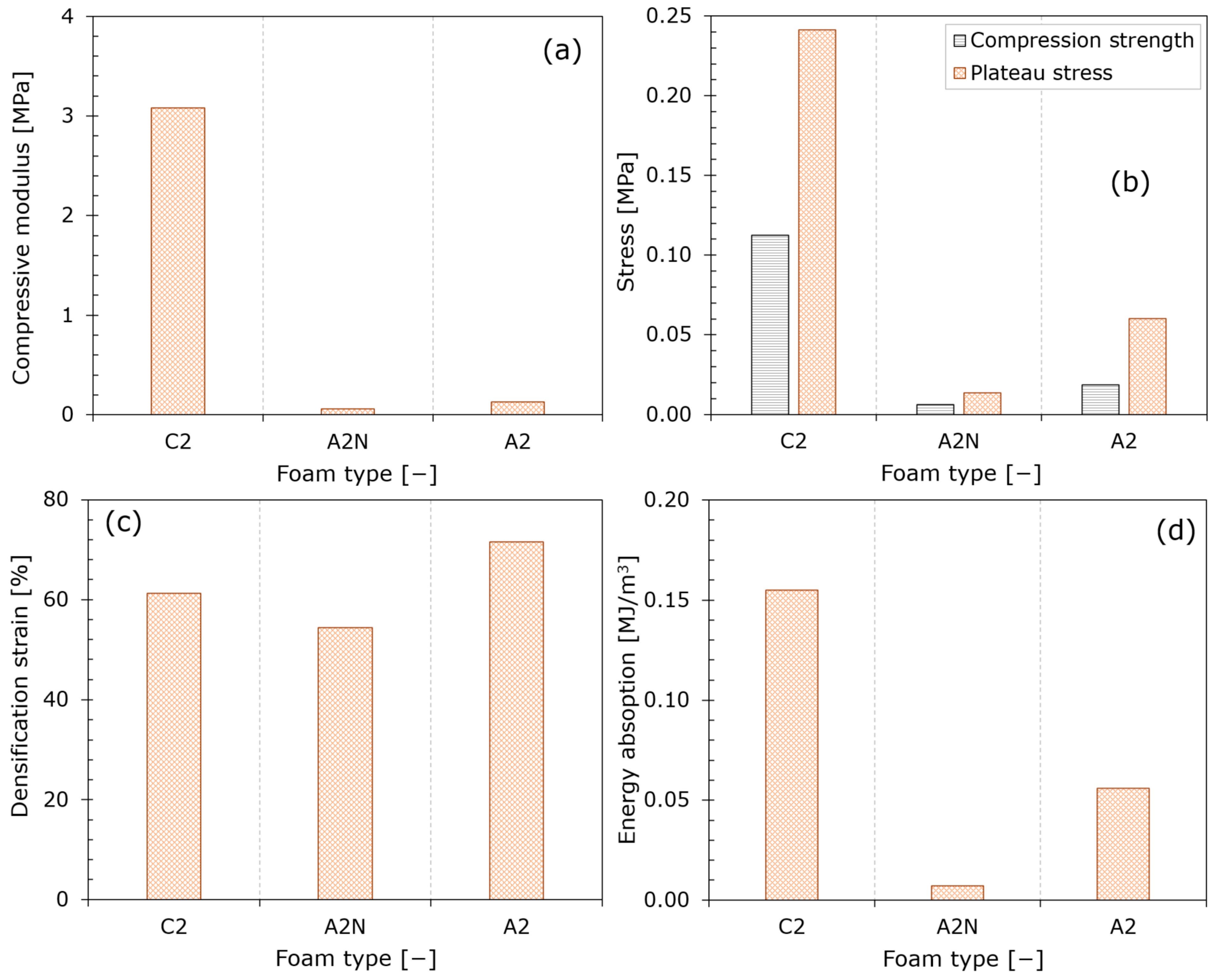
The compressive properties of foams C2, A2, and A2N are summarized in Figure 5, revealing clear distinctions in stiffness, strength, densification strain, and EA. Foam C2 exhibits the highest stiffness, with a compressive modulus (E) of 3.08 MPa (Figure 5a), and the highest strength-related parameters, including a compressive strength (CS) of 0.21 MPa and a plateau stress (PS) of 0.15 MPa (Figure 5b). By contrast, A2 and A2N show significantly lower E of 0.13 MPa and 0.06 MPa, respectively. Their PSs remain limited to 0.06 MPa (A2) and 0.01 MPa (A2N), reflecting their reduced load-bearing capacity. The densification strain (εd) values (Figure 5c) further differentiate the materials: A2 densifies at 71.5% strain, the highest among the samples; C2 densifies at ~61%; and A2N reaches εd at 54.4%. EA (Figure 5d) mirrors these trends. Foam C2 absorbs 0.15 MJ/m3, outperforming A2 (0.06 MJ/m3) and A2N (<0.01 MJ/m3). Despite its broad deformation interval, A2 shows only moderate EA due to its low PS, while A2N exhibits minimal performance across all metrics. Overall, C2 demonstrates superior stiffness, strength, and EA, whereas A2 combines low rigidity with large strain capacity, and A2N shows the weakest mechanical response.
Figure 5.
Compression-derived mechanical properties: modulus (a), stresses (b), densification strain (c), and absorbed energy (d).
The mechanical behavior of the foams is consistent with the structural changes induced during processing. In the case of A2N, the reduced stiffness and strength can be attributed to the growth of NH4Cl crystals inside the cells during treatment with NH3, CO2, and H2O vapor. These crystals generate cracks in the cell walls and weaken the carbon framework, as also reflected in the SEM observations reported for treated versus untreated samples. Following the sublimation of NH4Cl, the larger pores tend to collapse, resulting in a more fragile structure with diminished load-bearing capacity. Preventing such degradation requires heat treatment conditions that inhibit NH4Cl formation or ensure its removal without compromising the integrity of the pore network. These effects highlight the critical influence of NH4Cl formation and sublimation on the mechanical resilience of the foams and reinforce the need for controlled thermal treatment strategies when such materials are intended for applications requiring long-term structural stability.
3.3. Optical Microscopy
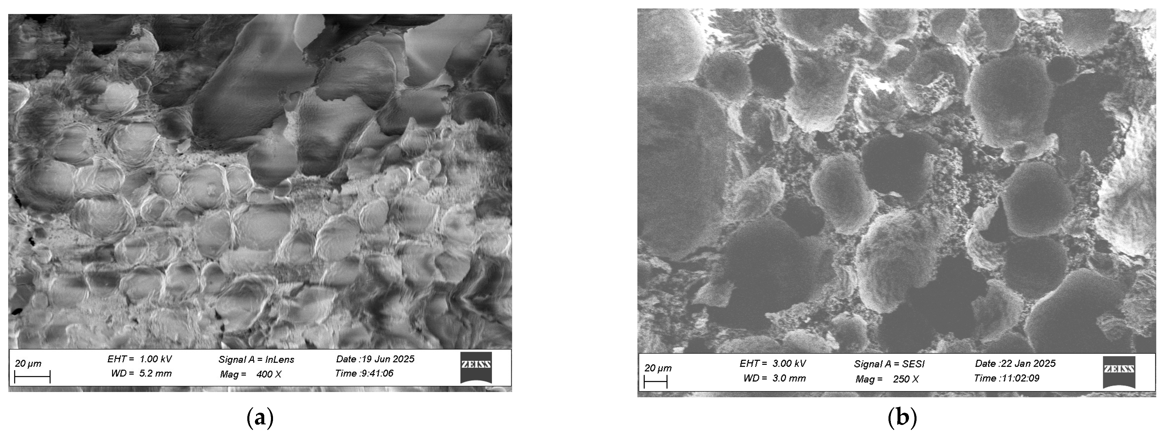
The SEM images presented in Figure 6 provide valuable insight into the morphological evolution of the foam material synthesized from CaCl2 and glucose under thermal pressure in an autoclave.
Figure 6.
SEM micrographs showing morphological evolution of CaCl2–glucose-derived foam structure (C1 sample) (a) and Water washed sample (b).
In Figure 6a the foam exhibits early signs of pore formation and partial breakdown of cell walls. These features are attributed to the formation of gas–solid mixture, which locally disrupt the carbon matrix. Figure 6b demonstrates tunable porosity, which can be modulated by adjusting the water washing and thermal treatment parameters.
The conversion of CaCl2 to CaCO3 during ammonia exposure not only alters the chemical environment but also enhances the mechanical and morphological stability of the final material. This is supported by Guo et al. [48], who observed that NH4Cl additives influence phase transitions and micromorphology in ceramic systems, reducing transition temperatures and promoting uniform porosity. In our system, the resulting foam—with its open, interconnected pore network—shows promise for filtration, thermal insulation, and as a scaffold for catalytic or adsorption-based applications. The ability to manipulate porosity through controlled chemical pathways offers a versatile platform for designing advanced porous materials with tailored structural and functional properties. C2 foams show smaller, more uniform pores, which limit long-range gas diffusion and enhance barrier properties. Such control over pore architecture, combined with the in situ formation of CaCO3, highlights the potential of these foams to be engineered as building materials, where tunable porosity and enhanced barrier properties can be leveraged to achieve both mechanical stability and efficient thermal insulation.
3.4. Thermogravimetry Recorded in Air
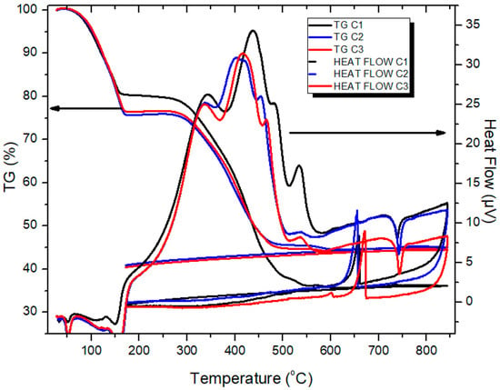
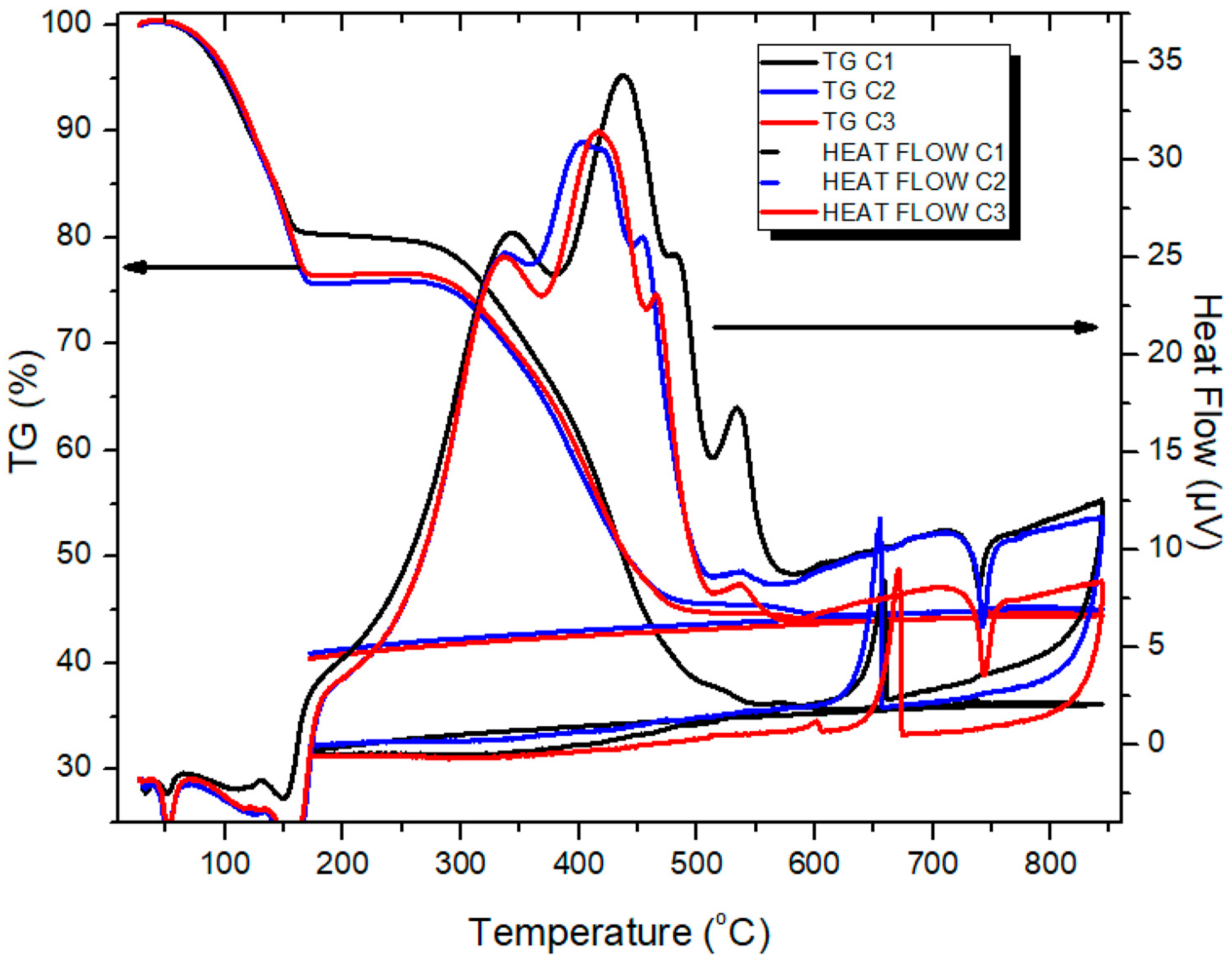
In the TG curves, mass loss occurs in two main stages. The first weight loss, up to approximately 170 °C, is primarily attributed to the decomposition of CaCl2 × XH2O. Because the calcium chloride crystal hydrates that crystallize with 6 and 4 water molecules, respectively, according to reactions R4–R7, melt at temperatures of approximately 30 and 45.4 °C, the water formed will be in liquid form and will evaporate along with the water adsorbed on the carbon mass. The similarity between our results and those of Pathak et al. [49] reinforces the interpretation that the early-stage mass loss is governed by hydrate decomposition and water release mechanisms. However, our foam system introduces an additional complexity: the porous carbon matrix facilitates vapor migration and may enhance water desorption kinetics compared to bulk salt systems. This distinction highlights the role of pore architecture in modulating thermal behavior under oxidative conditions. In the DTA spectrum, the melting of CaCl2 × 4H2O is manifested by small endothermic peaks around 50 °C (Figure 7) for samples C1–C3). The thermal behavior observed in our TG curves is further supported by the work of Karunadasa [50], who examined the dehydration of calcium chloride using high-temperature X-ray powder diffraction. His study confirms the presence of intermediate hydrates such as CaCl2·4H2O and CaCl2·2H2O, which remain stable at room temperature and begin to decompose progressively upon heating. In our system, the initial mass loss up to 170 °C corresponds well with this staged dehydration, suggesting that the foam matrix retains both surface-bound and structurally integrated water. The presence of carbon also introduces additional thermal pathways, which may influence the rate and completeness of dehydration. These distinctions highlight the importance of matrix composition and microstructure in modulating thermal decomposition behavior under oxidative conditions. The loss of the last two water molecules occurs at temperatures between 100 and 170 °C, manifested by two other endothermic peaks at temperatures around 120 and 170 °C.
Figure 7.
TG/DTA and comparative of C1–C3 samples recorded in air.
The reactions that take place are
CaCl2 × 6H2O → CaCl2 × 4H2O + 2H2O,
CaCl2 × 4H2O → CaCl2 × 2H2O + 2H2O,
CaCl2 × 2H2O → CaCl2 × H2O + H2O,
CaCl2 × H2O → CaCl2 (anhydrous) + H2O.
At temperatures ranging from 270 °C to 600 °C, the mass loss observed in air is predominantly due to the oxidation of the glucose-derived carbon structure. The exothermic peaks appearing above 270 °C suggest a complex decomposition pathway involving at least four partially superimposed sub-stages, likely reflecting the progressive breakdown of carbon domains with varying degrees of oxidation. The staged dehydration behavior revealed by TG/DTA not only clarifies the thermal stability of the CaCl2–carbon foams but also points to practical opportunities for their use in construction, where controlled water release and endothermic buffering could enhance both moisture regulation and fire resistance in insulation systems.
TG analysis also enabled the quantitative determination of CaCl2 content in the samples, calculated as 45.0% for C1, 59.5% for C2, and 57.38% for C3, consistent with the initial glucose-to-salt ratios used during synthesis. These values confirm the reproducibility of salt incorporation and validate the compositional control achieved during foam preparation.
Upon further heating, an endothermic peak near 750 °C is observed during the heating ramp, followed by an exothermic peak around 650 °C during cooling. These thermal events correspond to the melting and crystallization of CaCl2, respectively. The temperature difference between these transitions—approximately 100 °C is attributed to the supercooling phenomenon, where the salt crystallizes at a lower temperature than its melting point due to delayed nucleation and thermal hysteresis. This behavior is consistent with the findings of Eberbach et al. [51], who reported that CaCl2 exhibits path-dependent hydration and crystallization behavior, with significant sensitivity to vapor pressure, cooling rate, and matrix confinement. In our foam system, the porous carbon architecture likely influences the crystallization kinetics by modulating heat transfer and restricting nucleation sites, thereby amplifying the supercooling effect.
These values align with the initial glucose-to-salt ratios, validating the compositional control during synthesis and supporting the reproducibility of the foam formulation. The TG/DTA data reveal that the thermal behavior of the samples is governed by a combination of hydrate decomposition, carbon oxidation, and salt phase transitions. C1, with the lowest CaCl2 content, shows weaker signals around 50 °C, 120 °C, and 170 °C, indicating fewer hydrate transitions. In contrast, C2 and C3 exhibit more pronounced endothermic peaks, consistent with the presence of CaCl2·6H2O and CaCl2·4H2O, as previously reported in phase change material studies [52]. This suggests that higher salt loading promotes more extensive hydrate formation during synthesis. All samples exhibit a distinct thermal profile, with an endothermic peak near 750 °C corresponding to the melting of CaCl2, followed by an exothermic peak around 650 °C as crystallization occurs during cooling. The reproducible incorporation of CaCl2 and its well-defined phase transitions, amplified by the porous carbon matrix, highlight the potential of these foams to function as thermally responsive building materials, where controlled salt loading and supercooling behavior can be exploited to enhance insulation efficiency, moisture regulation, and fire-resistant performance
3.5. FT-IR
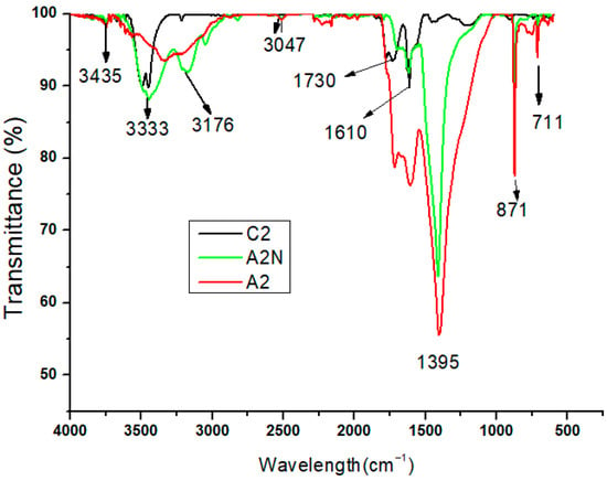
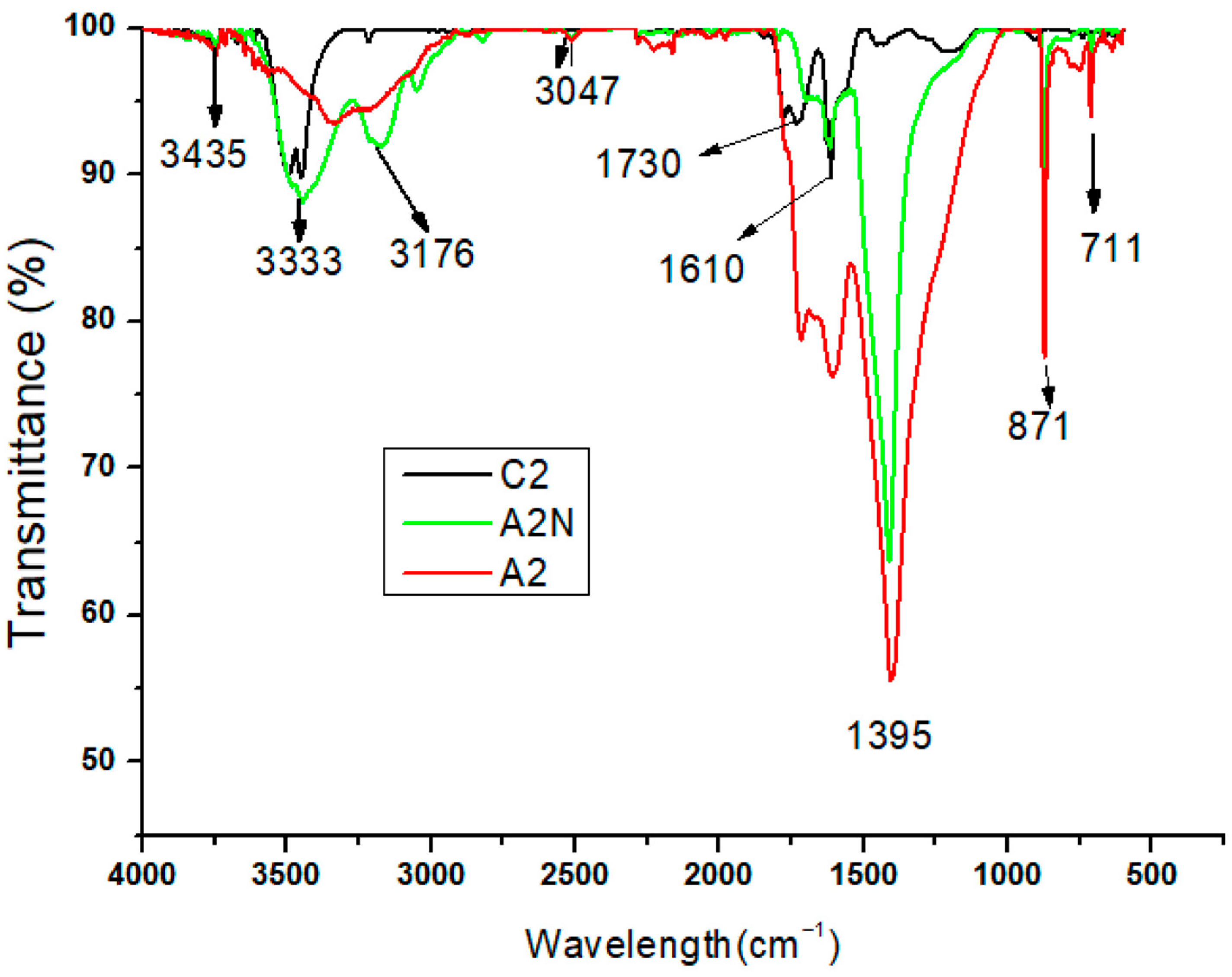
FTIR spectra of the three samples (C2, A2N, and A2) are shown in Figure 8. All spectra feature a absorption band centered around 3435 cm−1.
Figure 8.
FTIR Spectra of Foam Samples C2, A2N (Ammonia-Treated) and A2 (Post-Sublimatio) corresponding to G/C Ratio of 1.5.
This band is due to O–H stretching vibrations from adsorbed water or hydroxyl groups linked to hydrated calcium salts. A band at 3333 cm−1 matches with combination or overtone vibrations typical of CaCO3 polymorphs. In the spectrum of sample A2N, there are two additional absorptions at 3176 and 3047 cm−1 that correspond to the N–H stretching modes of ammonium species, indicating the presence of NH4Cl. In the carbonate region, all three spectra show a strong asymmetric stretching band of the CO32− group at 1395 cm−1. This is accompanied by the out-of-plane bending vibration at 871 cm−1 and the in-plane bending vibration at 711 cm−1. In the C2 spectrum (black), the absence of carbonate-specific bands indicates that no crystalline CaCO3 phase is present. Instead, the spectrum is dominated by weak O–H stretching and broad background features, characteristic of amorphous carbonaceous frameworks and residual hydroxylated species. This observation aligns with previous reports on hydrothermal carbonization of glucose in the presence of CaCl2, where mineral phases do not form unless post-treatment with CO2 or alkaline agents is applied [53,54]. In contrast to the amorphous carbon matrix observed in C2, the FTIR spectra of A2 (red) and A2N (green) display the diagnostic triplet of calcite (CaCO3): the asymmetric stretching vibration of the carbonate ion at 1395 cm−1, the out-of-plane bending at 871 cm−1, and the in-plane bending at 711 cm−1. These three bands are widely recognized as fingerprint features of calcite and have been consistently reported in both Raman and infrared studies of calcium carbonate polymorphs [55,56]. Their presence confirms the successful in situ conversion of CaCl2 to calcite during the CO2–NH3–H2O vapor-phase treatment applied to A2N, and the retention of this phase in A2 following NH4Cl sublimation. In addition to the carbonate bands, A2N exhibits two distinct absorptions at 3176 cm−1 and 3047 cm−1, which correspond to N–H stretching vibrations of ammonium ions. These features are characteristic of NH4Cl, and their positions fall within the 3300–3000 cm−1 range typically assigned to NH4+ species in crystalline environments [57,58]. Their absence in C2 and only weak presence in A2 strongly suggest that NH4Cl is introduced during the vapor-phase reaction (reaction (3)) and is subsequently removed by thermal sublimation, as also confirmed by XRD data. This spectral evolution aligns with the known thermal behavior of ammonium chloride–ammonia systems, where NH4Cl can volatilize or sublimate upon controlled heating [44]. The FTIR data thus provide complementary evidence to the XRD results, confirming both phase identity and treatment-dependent compositional changes across the foam series. The FTIR data thus provide complementary evidence to the XRD results, confirming both phase identity and treatment-dependent compositional changes across the foam series, which are strongly influenced by the initial glucose-to-CaCl2 ratio. The identification of calcite fingerprint bands alongside treatment-dependent NH4Cl absorptions demonstrates that both phase composition and pore architecture can be chemically engineered, offering a pathway to foams with tailored mechanical stability and barrier properties that are highly relevant for their prospective use as multifunctional building materials with integrated insulation and environmental control capabilities.
3.6. Determination of Ammonium Concentration Using Colorimetric Analysis
This portable device operates within a detection range of 0.00–3.00 ppm (mg/L), with a resolution of ±0.05 ppm and an accuracy of ±5% at 25 °C, ensuring reliable quantification under controlled conditions. Samples were collected after exposure to the NH3–CO2–H2O vapor mixture and 60 h of heat treatment, ensuring that no residual ammonia remained in the system during analysis. The analysis was performed according to the manufacturer’s protocol, using pre-measured reagents and a fixed reaction time to ensure consistency. The resulting absorbance values were compared against a calibration curve generated from standard ammonium solutions. The results confirmed that no residual ammonia was present in the system after heat treatment, indicating complete removal. The confirmed absence of residual ammonia after vapor treatment and prolonged heating underscores the chemical stability of the foams, an essential prerequisite for their safe integration into building applications where long-term compositional reliability and environmental compatibility are critical.
3.7. Determination of Water Absorption Capacity
The water absorption capacity of the foam was evaluated by recirculating sub-saturated water vapor through a bed of absorbent material housed in a Teflon mini-reactor. The vapor flow rate was maintained at 5 mL/s, and the temperature was stabilized at 28 °C. For each test, 390 mg of absorbent material was placed at the reactor’s opening (diameter: 12 mm) on a polymer mesh with a mesh size of 600 µm. The sample was compacted under a pressure of 23,719.46 Pa, and a second mesh was placed on top to secure the material. The reactor was then hermetically sealed, and its total mass was recorded at regular time intervals to monitor water uptake. At 25 °C, using a CaCl2 solution with a mass concentration of 25.27%, humidified air was generated with a water vapor concentration of approximately 0.0115 mg H2O/cm3. This controlled vapor stream was then passed through the absorbent material bed to evaluate its water uptake capacity.
To generate air with controlled humidity, a bubbling system was employed. Air was passed through a calcium chloride (CaCl2) solution of known concentration, producing sub-saturated vapor. Aerosols were removed using a 0.2 µm pore-size filter, and the humidity of the incoming air was measured in-line using a calibrated hygrometer positioned just before the reactor inlet. It is known that the dependence of the relative vapor pressure π, on the mass fraction, ξ, of dissolved CaCl2 and on temperature for an aqueous CaCl2 solution, defined as the ratio between the vapor pressures of the solution and the saturated water vapor, both determined at the same temperature, is given by an equation that depends on two functions, π25 and f(x,q). The function π25 provides the equation for the dependence of the relative pressure π determined at a temperature of 25 °C on the mass fraction ξ, while the function f(x,q) is a correction function that extends the validity of the equation over the entire temperature range. The dependence of the relative vapor pressure of the CaCl2 solution on the functions π25 and f(x,q) is of the following form [59]:
where
is the vapor pressure of liquid water at temperature T;
ξ is the mass fraction of CaCl2 dissolved in the solution.
Here
θ is reduced temperature;
T is absolute temperature, K;
Tc,H2O is the critical temperature of water (647.096 K),
where
and
This air was then passed through a bed of absorbent material for analysis of water uptake.
Table 1.
Polynomial coefficients for the calculation of π25ξ.
The temperature dependence of the saturated water vapor pressure, expressed in Pa, is given by the Wexler equation [60]:
Table 2.
Coefficients of the Wexler equation.
The concentration of water vapor in moist air, expressed in mg/cm3, is given by the relation:
where:
π—relative vapor pressure of aqueous calcium chloride solutions;
MH2O—molar mass of water (18.02 g/mol);
R—universal gas constant [Pa·m3/mol·K]
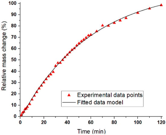
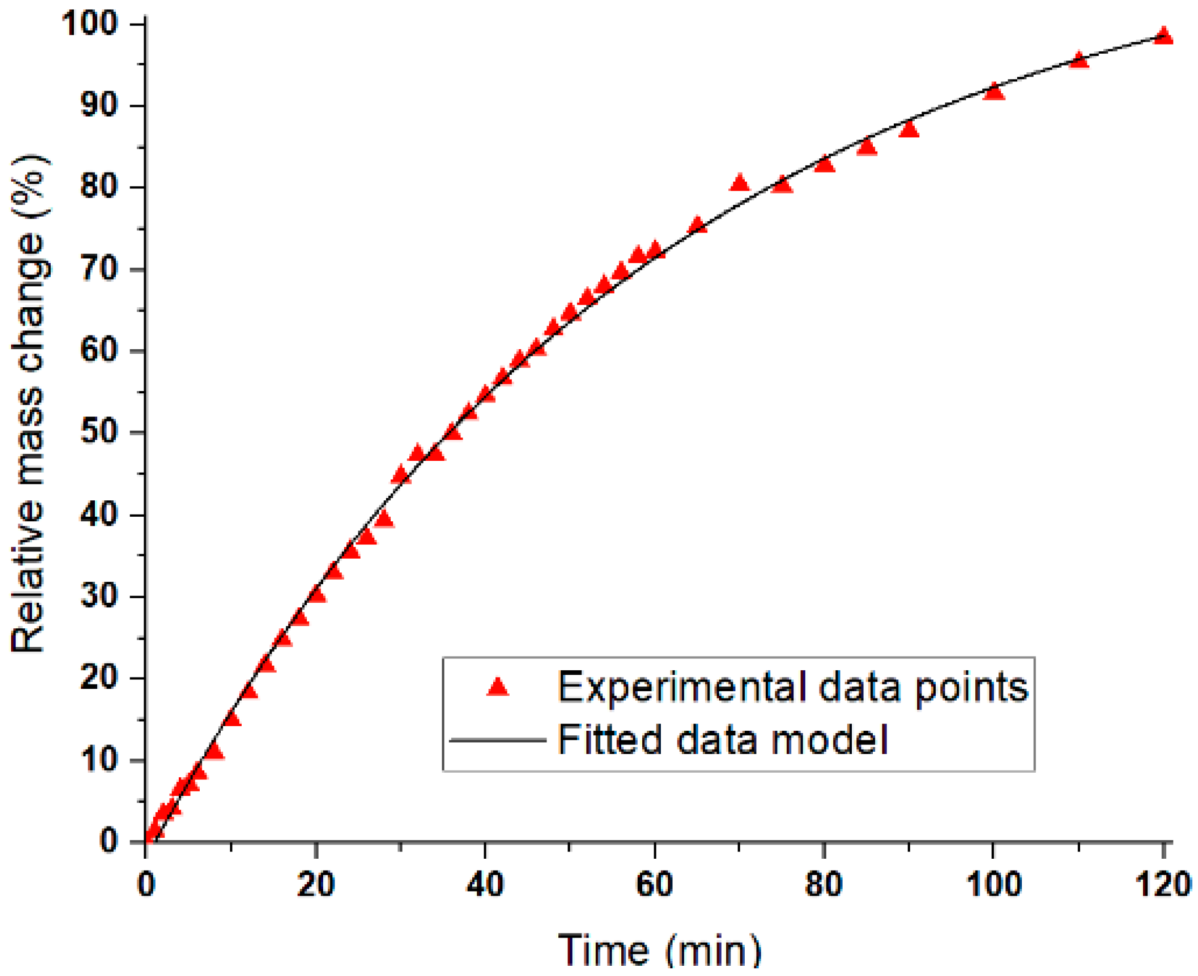
The graphical representation of the dependence between relative vapor pressure and CaCl2 concentration is shown in Figure 9.
Figure 9.
Time-resolved relative mass change (%) of the absorbent material during exposure to sub-saturated water vapor at 25 °C. Experimental data (red triangles) are fitted with an exponential decay model (black curve), indicating rapid initial uptake followed by saturation. Model parameters: A_1 = 114.87 ± 1.46, t_1 = −116.32 ± 1.31, y_0 = 60.37 ± 1.47; R2 = 0.99871.
A gradual decrease in absorption capacity over time is observed; in the first 30 min, the sample completely absorbs the water vapor from the air, according to graph 8. The fitted exponential decay model describes the kinetics of water vapor uptake, where Δ1 and t1 represent the characteristic amplitude and time constant of the absorption process, respectively, and y0 corresponds to the equilibrium offset. The high coefficient of determination (R2 = 0.99871) demonstrates that the model accurately captures the experimental behavior, with rapid initial uptake followed by saturation. This statistical validation supports the reproducibility of the observed absorption kinetics.
Table A1 (Appendix A) represents the time-resolved mass measurements of the absorbent foam during exposure to sub-saturated water vapor at 25 °C. The initial dry mass was 56.3510 g, and subsequent increases reflect progressive water uptake. The column “Δ (g)” indicates cumulative mass gain relative to the initial mass, while “Δ Drop (g)” captures the incremental change between consecutive time points.
As shown in Figure 9, the foam absorbed water vapor efficiently during the first 30 min, after which the uptake rate declined, indicating the onset of saturation.
The foam achieved an absorption efficiency exceeding 98% within 2 h. Initially, CaCl2 absorbed water to form sequential hydrates—CaCl2·2H2O, CaCl2·4H2O, and CaCl2·6H2O—before dissolving into the additionally absorbed water. The resulting liquid phase wetted the foam’s cellular walls, increasing the effective surface area for vapor–liquid exchange and enhancing the absorption rate during intermediate stages.
The foam demonstrated strong hygroscopic behavior, reaching a cumulative uptake of 0.384 g. The absorption profile featured a rapid initial gain (Δ = 0.0845 g at 14 min), followed by a gradual plateau (Δ = 0.3840 g at 120 min), consistent with diffusion-limited transport as internal pores became saturated. The “Δ Drop” metric revealed distinct kinetic phases, with values exceeding 0.01 g in successive intervals, suggesting intensified uptake driven by microstructural rearrangements or thermal feedback. The absorption mechanism follows a known hydrate formation sequence:
- -
- Initial uptake forms CaCl2·2H2O;
- -
- Progresses to CaCl2·4H2O and CaCl2·6H2O;
- -
- Excess water dissolves CaCl2·6H2O, forming a liquid phase.
This liquid wets the foam’s cellular walls, increasing the geometric surface area of the vapor–liquid interface and enhancing uptake. The presence of CaCl2 in the vapor stream further moderates partial pressure, enabling controlled condensation and deeper vapor penetration into the foam matrix. These behaviors align with documented effects in open-cell foams, where capillary condensation improves transport and retention.
Collectively, the results confirm that Foam C3, with its high CaCl2 content and engineered porosity, is highly effective for ambient-temperature dehumidification. Its > 98% absorption efficiency within 2 h, combined with mechanical resilience and scalable synthesis, positions it as a promising candidate for air treatment, moisture control in packaging, and passive climate regulation technologies.
3.8. Acetic Acid Vapor Absorption Tests
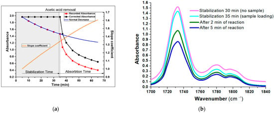
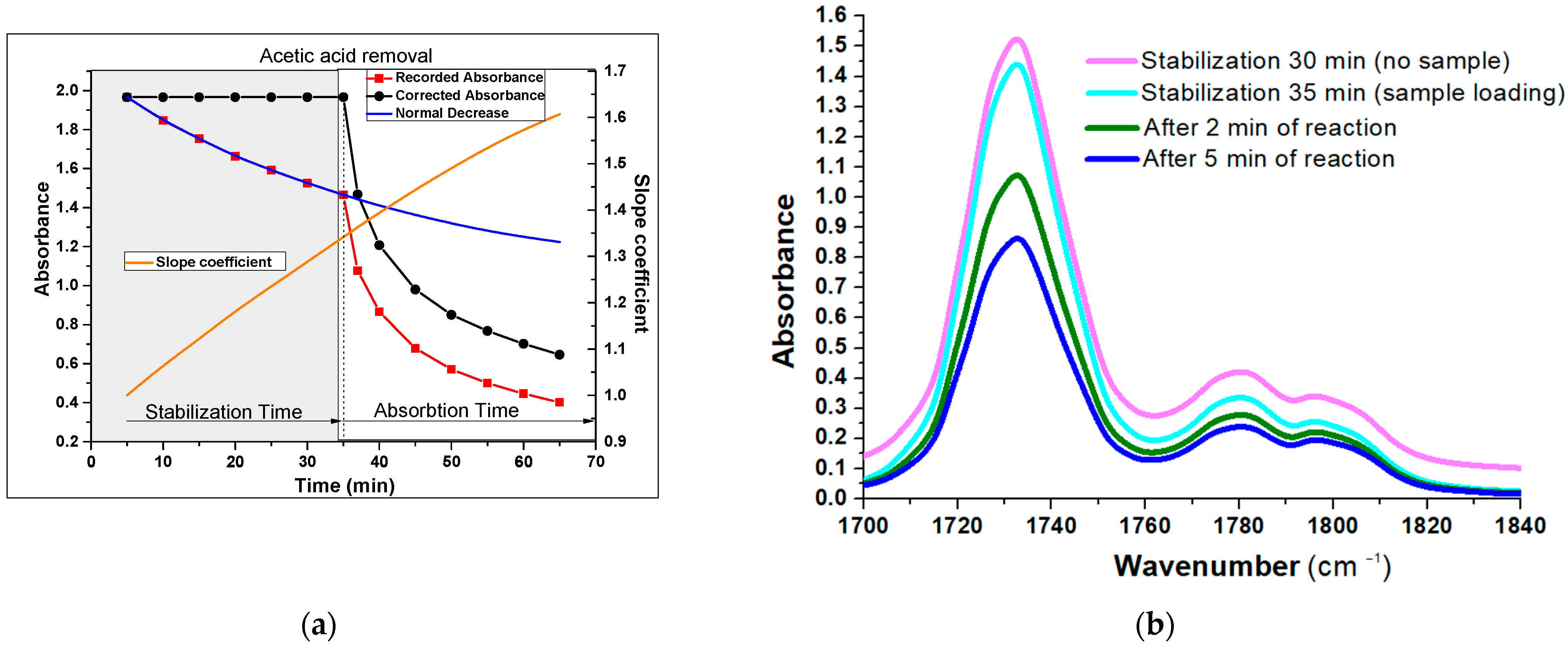
As can be seen in Figure 10, during the first 35 min of stabilization, there is a decrease in the absorbance value (recorded absorbance curve) 1. This is probably due to the adsorption of acetic acid on the inner walls of the reactor and its dissolution in the silicone grease used to seal the valves and window gaskets.
Figure 10.
(a) Absorbance profile over time during acetic acid vapor exposure. The stabilization phase (0–30 min) shows a gradual decrease in recorded absorbance (red squares); The slope coefficient (orange) quantifies the rate of change in absorbance (b) Absorbance Evolution in the carboxyl vibrations.
Subfigure a show the change in absorbance and its slope during stabilization and acetic acid removal, while subfigure b presents the evolution of the carbonyl peak (~1730 cm−1) during stabilization and early reaction. Silicone grease is composed of polydimethylsiloxane and amorphous silicon dioxide as a thickening agent. The dissolution process is diffusion-limited. After powder release at 35 min, the absorption phase begins, with corrected absorbance (black circles) and fitted curve (blue line) indicating active uptake and reaction progression; After 35 min, the powder was released into the gas cell. During absorption, the following reaction takes place:
CaCO3 + 2CH3COOH → Ca(CH3COO)2 + H2O + CO2.
Strong gas absorption occurs in the first 5 min, after which absorption is limited by the diffusion of the gas into the solid porous mass. Water vapor and the formed CO2 are adsorbed onto the porous carbon; for this reason, the characteristic CO2 band does not appear in the FTIR spectra. Overall, the foam’s performance supports its applicability in dehumidification systems, moisture control in packaging, and passive climate regulation technologies, offering a scalable and eco-friendly solution for vapor-phase water capture.
The chemical reaction (R8) is evidenced by the decrease in the absorption bands at wavenumbers 1788, 1430, and 1382 cm−1, corresponding to the C=O stretching, CH3 deformation, and OH bending vibrations of the carboxyl, methyl, and hydroxyl groups in the gaseous CH3COOH molecule (Figure 10b). The combined water and acetic acid vapor absorption experiments demonstrate that the CaCl2–carbon foams are not only highly effective hygroscopic materials, capable of rapid and sustained uptake under ambient conditions, but also chemically reactive sorbents that undergo in situ transformations (e.g., CaCO3 → Ca(CH3COO)2) during acid exposure. This dual functionality—moisture regulation through hydrate formation and pollutant capture Via acid neutralization—underscores the versatility of the foams as scalable, eco-friendly platforms for integrated dehumidification, packaging protection, and passive climate regulation technologies.
Intense gas absorption is observed within the first 5 min, followed by a diffusion-limited regime as acetic acid penetrates the porous solid. Both water vapor and the generated CO2 are adsorbed onto the carbon matrix, which explains the absence of the characteristic CO2 band in the FTIR spectra.
These results reinforce the foam’s suitability for dehumidification, moisture control in packaging, and passive climate regulation, highlighting its scalability and ecological potential for vapor-phase capture applications.
3.9. Economic Feasibility and Scalability
A key advantage of the one-pot synthesis route is its simplicity. The process relies on inexpensive and widely available precursors—glucose and calcium chloride—whose combined cost is typically below $2 per kg of foam material [61]. Energy consumption is primarily associated with autoclave heating at 220 °C for 24 h, which translates into an estimated $5–10 per kg depending on batch size and electricity costs [62]. Additional steps, such as CNC machining and vapor-phase treatment, add only marginal expenses. Overall, the production cost of glucose–CaCl2 foams is estimated at $10–20 per kg at laboratory scale, with potential reductions at industrial scale through batch processing.
When compared to existing materials, the economic advantage becomes clearer. Silica foams, while offering excellent thermal insulation, remain costly at $100–300 per kg [63,64] due to complex drying processes and fragile handling requirements. Activated carbon, on the other hand, is inexpensive ($5–15 per kg) but lacks multifunctionality, offering adsorption capacity without the combined benefits of moisture regulation and pollutant capture [65]. Glucose–CaCl2 foams occupy a middle ground: they deliver balanced mechanical resilience, strong hygroscopic behavior, and chemical reactivity at a fraction of the cost of silica foams, while offering broader functionality than activated carbon.
Scalability challenges remain, particularly in maintaining uniform pore architecture and consistent salt loading across larger batches. Managing byproducts during vapor-phase treatments also requires optimization. Nevertheless, the simplicity of the synthesis and the affordability of raw materials make these foams promising candidates for building material applications, especially in resource-poor settings where cost efficiency is critical. The trade-off between performance and cost is favorable: while slightly less insulating than silica foams, glucose–CaCl2 foams provide multifunctional benefits at a significantly lower price point, positioning them as scalable, eco-friendly alternatives for passive climate regulation and insulation.
4. Conclusions
This study shows that the composition and processing conditions of glucose–CaCl2 foams directly determine their structural and functional performance. By tuning porosity and microstructure, we established clear links between material architecture and performance. The mechanical tests revealed a tunable response, ranging from higher-stiffness foams with enhanced energy absorption to more compliant structures with extended strain capacity, while independent structural analyses confirmed the features governing vapor transport and chemical reactivity. Thermal analysis confirmed reproducible salt incorporation and staged dehydration of CaCl2 hydrates, with the carbon matrix accelerating vapor release compared to bulk salts. Spectroscopic and microscopic evidence further validated the in situ conversion of CaCl2 to calcite and the removal of NH4Cl, transformations that control pore opening and stability. Functionally, the foams showed strong hygroscopic behavior, efficiently capturing water vapor under ambient conditions, and demonstrated chemical reactivity toward acetic acid, neutralizing it through carbonate chemistry. These combined properties—including mechanical resilience, thermal buffering, moisture regulation, and pollutant capture—are directly relevant to building applications. Taken together, the results position glucose–CaCl2 foams as scalable, eco-friendly candidates for construction materials, particularly in insulation and passive climate regulation. Their tunable porosity and integrated chemical functionality offer a pathway to building components that combine durability with environmental control. Future work will focus on optimizing synthesis parameters to balance mechanical strength with sorption capacity and on evaluating long-term performance under realistic building conditions. In addition to their functional performance, the foams demonstrate economic feasibility, with low-cost precursors and moderate energy requirements positioning them as competitive alternatives to silica foams and activated carbon for large-scale building applications. Despite the promising results, several limitations must be acknowledged. The scalability of the synthesis process remains to be fully validated, as maintaining uniform pore architecture and consistent salt incorporation in large-scale batches poses technical challenges. Long-term stability under fluctuating humidity, temperature, and pollutant exposure also requires systematic evaluation to ensure durability in real building environments. Furthermore, while preliminary cost estimates suggest competitive production compared to silica aerogels, a comprehensive techno-economic analysis is needed to confirm feasibility at industrial scale. Future research should focus on optimizing synthesis parameters to balance mechanical strength with sorption capacity, while also investigating accelerated aging tests to assess performance over extended lifetimes. Expanding applications beyond building insulation—such as indoor air purification, moisture buffering in heritage conservation, or integration into composite materials—could broaden the impact of these foams. Finally, considering climate change challenges, the development of multifunctional, low-cost materials that simultaneously regulate indoor environments and mitigate pollutant loads represents a critical pathway toward sustainable construction solutions.
Author Contributions
Conceptualization, R.B. (Radu Banica); methodology, F.S.R.; software, N.B. and E.L.; validation, R.B. (Raul Bucur) and F.S.R.; formal analysis, F.S.R., C.M. and R.B. (Radu Banica); investigation, F.S.R., R.B. (Radu Banica), D.R., E.L. and R.B. (Radu Banica); resources, F.S.R.; data curation, M.P.M., E.L. and F.S.R.; writing—R.B. (Raul Bucur), F.S.R., E.L. and C.M.; visualization, F.S.R.; supervision, R.B. (Radu Banica); project administration, R.B. (Radu Banica); funding acquisition, F.S.R. All authors have read and agreed to the published version of the manuscript.
Funding
This work was supported by a grant of the Ministry of Research, Innovation, and Digitization, CCCDI-UEFISCDI, project number PN-IV-P8-8.3-PM-RO-BE-2024-0004 within PNCDI IV.
Data Availability Statement
All data used in this study were generated by the authors as part of their research activities. These data may be obtained from the corresponding authors upon request.
Conflicts of Interest
The authors declare no conflicts of interest.
Appendix A
This experimental configuration was selected following a series of preliminary trials, aimed at achieving the highest possible stability of the absorbance baseline prior to the release of the foam into the cell. To investigate vapor-phase interactions, acetic acid vapors were introduced into a sealed gas cell (path length: 100 mm; internal diameter: 40 mm; total volume: 125 cm3) equipped with KCl windows for infrared transmission. One of the windows was modified to integrate a PTFE-based dosing mechanism, allowing precise delivery of a defined foam mass directly into the cell without disrupting the sealed environment.
To minimize water vapor condensation during gas recirculation, the acetic acid solution was cooled in an ice bath prior to vapor generation. Additionally, aerosols were removed using a 0.2 µm polyethersulfone syringe filter (30 mm diameter), ensuring a clean vapor phase. Under these conditions, the system produced acetic acid vapors with a calculated partial pressure of 0.58 mmHg.
Gas circulation was maintained using a diaphragm-type micropump over a 120 min period. Once the system was sealed, 80 mg of foam was introduced into the cell, and FTIR spectra were collected at 300 s intervals for a total duration of 65 min. A schematic representation of the experimental setup is provided in Figure A1:
Figure A1.
Teflon sample container mounted in the KCl window (a) and the gas cell installed in the FTIR setup (b).
SEM Figure A2 illustrates the morphological changes in the foams following water washing. After carbonization, the foams exhibit compact cellular carbon structures interspersed with carbon–CaCl2 composites. Given the high solubility of CaCl2, treatment with water or saturated steam facilitates pore opening in regions where solid CaCl2 is embedded within the cell walls. However, in larger samples, limited water diffusion and the localized formation of saturated CaCl2 solutions may hinder complete dissolution.
The SEM image clearly reveals the development of open porosity after washing, confirming that the foam architecture can be tuned to yield either closed or open pores depending on the treatment conditions.
Figure A2.
Micrographs of (C1–C3) foams recorded after washing.
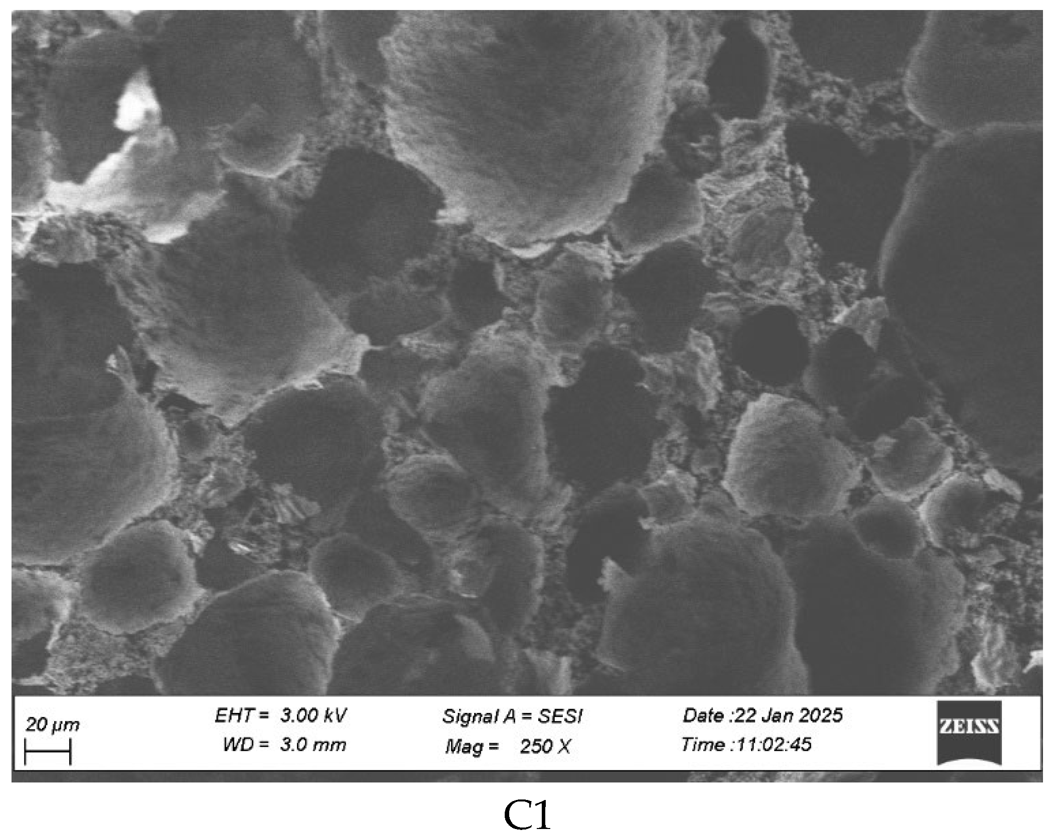
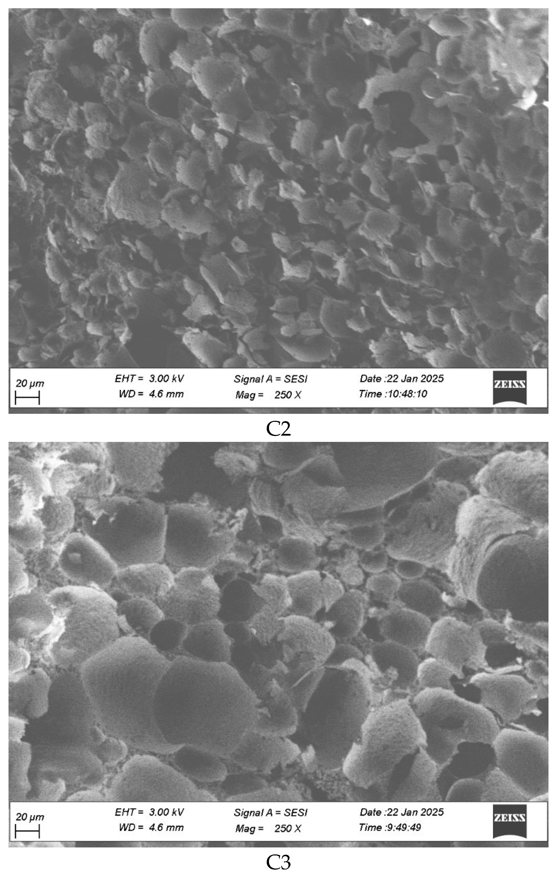
Table A1.
Time-resolved mass measurements of the absorbent material during vapor exposure, showing cumulative water uptake (Delta) and incremental changes (Delta Drop). Initial dry mass: 56.3510 g. The initial dry mass was 56.3510 g, and subsequent increases reflect progressive water uptake. The column “Δ (g)” indicates cumulative mass gain relative to the initial mass, while “Δ Drop (g)” captures the incremental change between consecutive time points.
References
- Kistler, S.S. Coherent Expanded Aerogels and Jellies. Nature 1931, 127, 741. [Google Scholar] [CrossRef] [Scilit]
- Niculescu, A.-G.; Tudorache, D.-I.; Bocioagă, M.; Mihaiescu, D.E.; Hadibarata, T.; Grumezescu, A.M. An Updated Overview of Silica Aerogel-Based Nanomaterials. Nanomaterials 2024, 14, 469. [Google Scholar] [CrossRef] [Scilit]
- Fricke, J.; Emmerling, A. Aerogels. J. Am. Ceram. Soc. 1992, 75, 2027–2035. [Google Scholar] [CrossRef] [Scilit]
- Idumah, C.I.; Ezika, A.C.; Okpechi, V.U. Emerging Trends in Polymer Aerogel Nanoarchitectures, Surfaces, Interfaces and Applications. Surf. Interfaces 2021, 25, 101258. [Google Scholar] [CrossRef] [Scilit]
- Mosoarca, C.; Hulka, I.; Șchiopu, P.; Rus, F.S.; Bănică, R. CaCO3-Infused Carbon Fiber Aerogels: Synthesis and Characterization. Ceramics 2024, 7, 777–795. [Google Scholar] [CrossRef] [Scilit]
- Banica, R.; Taranu, B.; Ladasiu, C.; Hulka, I.; Linul, P. Three-Dimensional Porous Electrode Based on Silver Nanowires for Hydrogen Sulfide Detection. Mater. Lett. 2021, 304, 130720. [Google Scholar] [CrossRef] [Scilit]
- Linul, P.; Bănică, R.; Grad, O.; Linul, E.; Vaszilcsin, N. Highly Electroconductive Metal-Polymer Hybrid Foams Based on Silver Nanowires: Manufacturing and Characterization. Polymers 2024, 16, 608. [Google Scholar] [CrossRef] [Scilit]
- Pekala, R.W.; Farmer, J.C.; Alviso, C.T.; Tran, T.D.; Mayer, S.T.; Miller, J.M.; Dunn, B. Carbon Aerogels for Electrochemical Applications. J. Non-Cryst. Solids 1998, 225, 74–80. [Google Scholar] [CrossRef] [Scilit]
- Maleki, H.; Hüsing, N. Current Status, Opportunities and Challenges in Catalytic and Photocatalytic Applications of Aerogels: Environmental Protection Aspects. Appl. Catal. B Environ. 2018, 221, 530–555. [Google Scholar] [CrossRef] [Scilit]
- Gan, G.; Li, X.; Fan, S.; Wang, L.; Qin, M.; Yin, Z.; Chen, G. Carbon Aerogels for Environmental Clean-Up. Eur. J. Inorg. Chem. 2019, 2019, 3126–3141. [Google Scholar] [CrossRef] [Scilit]
- Voiconi, T.; Linul, E.; Marşavina, L.; Sadowski, T.; Kneć, M. Determination of Flexural Properties of Rigid PUR Foams Using Digital Image Correlation. Solid State Phenom. 2014, 216, 116–121. [Google Scholar] [CrossRef] [Scilit]
- Mourshed, M.; Ahmed, R.; Kibria, M.G.; Islam Sarker, M.R. Carbon Foam for Next-Generation Electrochemical Energy Storage: Advances, Challenges, and Outlook. Energy Convers. Manag. X 2025, 28, 101281. [Google Scholar] [CrossRef] [Scilit]
- Job, N.; Pirard, R.; Marien, J.; Pirard, J.-P. Porous Carbon Xerogels with Texture Tailored by pH Control during Sol–Gel Process. Carbon 2004, 42, 619–628. [Google Scholar] [CrossRef] [Scilit]
- Raymundo-Piñero, E.; Azaïs, P.; Cacciaguerra, T.; Cazorla-Amorós, D.; Linares-Solano, A.; Béguin, F. KOH and NaOH Activation Mechanisms of Multiwalled Carbon Nanotubes with Different Structural Organisation. Carbon 2005, 43, 786–795. [Google Scholar] [CrossRef] [Scilit]
- Wang, J.; Kaskel, S. KOH Activation of Carbon-Based Materials for Energy Storage. J. Mater. Chem. 2012, 22, 23710–23725. [Google Scholar] [CrossRef] [Scilit]
- Biener, J.; Stadermann, M.; Suss, M.; Worsley, M.A.; Biener, M.M.; Rose, K.A.; Baumann, T.F. Advanced Carbon Aerogels for Energy Applications. Energy Environ. Sci. 2011, 4, 656–667. [Google Scholar] [CrossRef] [Scilit]
- Hong, J.-Y.; Wie, J.J.; Xu, Y.; Park, H.S. Chemical Modification of Graphene Aerogels for Electrochemical Capacitor Applications. Phys. Chem. Chem. Phys. 2015, 17, 30946–30962. [Google Scholar] [CrossRef] [Scilit]
- Gu, W.; Yushin, G. Review of Nanostructured Carbon Materials for Electrochemical Capacitor Applications: Advantages and Limitations of Activated Carbon, Carbide-Derived Carbon, Zeolite-Templated Carbon, Carbon Aerogels, Carbon Nanotubes, Onion-like Carbon, and Graphene. WIREs Energy Environ. 2014, 3, 424–473. [Google Scholar] [CrossRef] [Scilit]
- Moreno-Castilla, C.; Maldonado-Hódar, F.J. Carbon Aerogels for Catalysis Applications: An Overview. Carbon 2005, 43, 455–465. [Google Scholar] [CrossRef] [Scilit]
- Shen, Y.; Wu, Y. Review on Synthesis of Carbon Aerogels for CO2 Capture. Fuel 2025, 387, 134370. [Google Scholar] [CrossRef] [Scilit]
- Mohammadi, A.; Moghaddas, J. Synthesis, Adsorption and Regeneration of Nanoporous Silica Aerogel and Silica Aerogel-Activated Carbon Composites. Chem. Eng. Res. Des. 2015, 94, 475–484. [Google Scholar] [CrossRef] [Scilit]
- Cao, Y.; Cheng, Z.; Wang, R.; Liu, X.; Zhang, T.; Fan, F.; Huang, Y. Multifunctional Graphene/Carbon Fiber Aerogels toward Compatible Electromagnetic Wave Absorption and Shielding in Gigahertz and Terahertz Bands with Optimized Radar Cross Section. Carbon 2022, 199, 333–346. [Google Scholar] [CrossRef] [Scilit]
- Long, L.-Y.; Weng, Y.-X.; Wang, Y.-Z. Cellulose Aerogels: Synthesis, Applications, and Prospects. Polymers 2018, 10, 623. [Google Scholar] [CrossRef] [Scilit]
- Payanda Konuk, O.; Alsuhile, A.A.A.M.; Yousefzadeh, H.; Ulker, Z.; Bozbag, S.E.; García-González, C.A.; Smirnova, I.; Erkey, C. The Effect of Synthesis Conditions and Process Parameters on Aerogel Properties. Front. Chem. 2023, 11, 1294520. [Google Scholar] [CrossRef] [Scilit]
- Yao, Z.; Zhang, W.; Yu, X. Fabricating Porous Carbon Materials by One-Step Hydrothermal Carbonization of Glucose. Processes 2023, 11, 1923. [Google Scholar] [CrossRef] [Scilit]
- Chen, L.; Fan, Z.; Mao, W.; Dai, C.; Chen, D.; Zhang, X. Analysis of Formation Mechanisms of Sugar-Derived Dense Carbons via Hydrogel Carbonization Method. Nanomaterials 2022, 12, 4090. [Google Scholar] [CrossRef] [Scilit]
- Khandaker, T.; Islam, T.; Nandi, A.; Anik, M.A.A.M.; Hossain, M.S.; Hasan, M.K.; Hossain, M.S. Biomass-Derived Carbon Materials for Sustainable Energy Applications: A Comprehensive Review. Sustain. Energy Fuels 2025, 9, 693–723. [Google Scholar] [CrossRef] [Scilit]
- Titirici, M.-M.; Antonietti, M. Chemistry and Materials Options of Sustainable Carbon Materials Made by Hydrothermal Carbonization. Chem. Soc. Rev. 2009, 39, 103–116. [Google Scholar] [CrossRef] [Scilit]
- Qiu, J.; Huang, B.; Liu, Y.; Chen, D.; Xie, Z. Glucose-Derived Hydrothermal Carbons as Energy Storage Booster for Vanadium Redox Flow Batteries. J. Energy Chem. 2020, 45, 31–39. [Google Scholar] [CrossRef] [Scilit]
- Sun, J.; Wu, Z.; Ma, C.; Xu, M.; Luo, S.; Li, W.; Liu, S. Biomass-Derived Tubular Carbon Materials: Progress in Synthesis and Applications. J. Mater. Chem. A 2021, 9, 13822–13850. [Google Scholar] [CrossRef] [Scilit]
- Hou, Y.; Sheng, Z.; Fu, C.; Kong, J.; Zhang, X. Hygroscopic Holey Graphene Aerogel Fibers Enable Highly Efficient Moisture Capture, Heat Allocation and Microwave Absorption. Nat. Commun. 2022, 13, 1227. [Google Scholar] [CrossRef] [Scilit]
- Yuan, C.; Wang, J.; Weng, Y.; You, L.; Fang, L.; Luo, X.; Zheng, F. Konjac Glucomannan-Based Aerogels Exhibiting Ultra-Fast Solar-Driven Water Release Rate for Freshwater Harvesting in Low-Humidity Environments. J. Environ. Chem. Eng. 2025, 13, 119515. [Google Scholar] [CrossRef] [Scilit]
- Ello, A.S.; Yapo, J.A.; Trokourey, A. N-Doped Carbon Aerogels for Carbon Dioxide (CO2) Capture. Afr. J. Pure Appl. Chem 2013, 7, 61–66. [Google Scholar] [CrossRef]
- Franco, P.; Cardea, S.; Tabernero, A.; De Marco, I. Porous Aerogels and Adsorption of Pollutants from Water and Air: A Review. Molecules 2021, 26, 4440. [Google Scholar] [CrossRef] [Scilit] [PubMed]
- You, J.H.; Chiang, H.L.; Chiang, P.C. Comparison of Adsorption Characteristics for VOCs on Activated Carbon and Oxidized Activated Carbon. Environ. Prog. 1994, 13, 31–36. [Google Scholar] [CrossRef] [Scilit]
- Azadi, E.; Dinari, M. Green Synthesis, Characterization, and Properties of Carbon Aerogels. In Green Carbon Materials for Environmental Analysis: Emerging Research and Future Opportunities; ACS Symposium Series; American Chemical Society: Washington, DC, USA, 2023; Volume 1441, pp. 1–23. [Google Scholar]
- Balci, M.P.; Bayat, R.; Karakurt, C.; Sen, F. Development of Environmentally Friendly Lightweight Aerogel Composites as Sustainable Building Materials: High Insulation Performance and Application Potential. Int. J. Environ. Sci. Technol. 2025, 22, 14403–14416. [Google Scholar] [CrossRef] [Scilit]
- CARBIP—Circular Aerogel Reusable Building Insulation Products. Available online: https://carbip.eu/ (accessed on 11 December 2025).
- Lu, L.; Wang, H.; Yun, S.; Hu, J.; Wang, M. A State-of-the-Art Review of Novel Aerogel Insulation Materials for Building Exterior Walls. Energy Sources Part A Recovery Util. Environ. Eff. 2024, 46, 16231–16252. [Google Scholar] [CrossRef] [Scilit]
- Aerogel: The Innovative Force in Low-Carbon Architecture, Building a New Line of Defense for Safe and Green Living. Available online: https://insulatewool.com/news/aerogel-the-innovative-force-in-low-carbon-architecture-building-a-new-line-of-defense-for-safe-and-green-living (accessed on 6 December 2025).
- Wu, X.; Fu, J.; Lu, X. Hydrothermal Decomposition of Glucose and Fructose with Inorganic and Organic Potassium Salts. Bioresour. Technol. 2012, 119, 48–54. [Google Scholar] [CrossRef] [Scilit]
- Xu, Z.-X.; Shan, Y.-Q.; Zhang, Z.; Deng, X.-Q.; Yang, Y.; Luque, R.; Duan, P.-G. Hydrothermal Carbonization of Sewage Sludge: Effect of Inorganic Salts on Hydrochar’s Physicochemical Properties. Green Chem. 2020, 22, 7010–7022. [Google Scholar] [CrossRef] [Scilit]
- Ma, X.-Q.; Liao, J.-J.; Chen, D.-B.; Xu, Z.-X. Hydrothermal Carbonization of Sewage Sludge: Catalytic Effect of Cl− on Hydrochars Physicochemical Properties. Mol. Catal. 2021, 513, 111789. [Google Scholar] [CrossRef] [Scilit]
- Tomida, D.; Suzuki, K.; Katou, Y.; Yokoyama, C. Vapor Pressures and Liquid Densities of Ammonium Chloride + Ammonia Mixtures. J. Chem. Eng. Data 2008, 53, 1583–1586. [Google Scholar] [CrossRef] [Scilit]
- Khezrzadeh, O.; Mirzaee, O.; Emadoddin, E.; Linul, E. Anisotropic Compressive Behavior of Metallic Foams under Extreme Temperature Conditions. Materials 2020, 13, 2329. [Google Scholar] [CrossRef] [Scilit]
- Movahedi, N.; Linul, E. Radial Crushing Response of Ex-Situ Foam-Filled Tubes at Elevated Temperatures. Compos. Struct. 2021, 277, 114634. [Google Scholar] [CrossRef] [Scilit]
- Șerban, D.-A.; Linul, E. Fatigue Behaviour of Closed-Cell Polyurethane Rigid Foams. Eng. Fail. Anal. 2023, 154, 107728. [Google Scholar] [CrossRef] [Scilit]
- Guo, Q. Effect of NH4Cl Additives on the Phase Transformation and Morphology of α-Al2O3. Ceram. Silik. 2023, 67, 52–57. [Google Scholar] [CrossRef] [Scilit]
- Pathak, A.D.; Nedea, S.; Zondag, H.; Rindt, C.; Smeulders, D. A DFT-Based Comparative Equilibrium Study of Thermal Dehydration and Hydrolysis of CaCl2 Hydrates and MgCl2 Hydrates for Seasonal Heat Storage. Phys. Chem. Chem. Phys. 2016, 18, 10059–10069. [Google Scholar] [CrossRef] [Scilit] [PubMed]
- Sujith Karunadasa Dehydration of Calcium Chloride as Examined by High-Temperature X-Ray Powder Diffraction. Available online: https://acrobat.adobe.com/id/urn:aaid:sc:EU:5885d871-ee39-43c2-a7e0-f577959ab8cd (accessed on 10 April 2024).
- Eberbach, M.C.; Seo, H.; Shkatulov, A.I.; Tinnemans, P.; Huinink, H.P.; Fischer, H.R.; Adan, O.C.G. Path-Dependent Hydration and Dehydration of CaCl2. Cryst. Growth Des. 2025, 25, 5679–5688. [Google Scholar] [CrossRef] [Scilit]
- Xu, X.; Dong, Z.; Memon, S.A.; Bao, X.; Cui, H. Preparation and Supercooling Modification of Salt Hydrate Phase Change Materials Based on CaCl2·2H2O/CaCl2. Materials 2017, 10, 691. [Google Scholar] [CrossRef] [Scilit]
- Sevilla, M.; Fuertes, A.B. The Production of Carbon Materials by Hydrothermal Carbonization of Cellulose. Carbon 2009, 47, 2281–2289. [Google Scholar] [CrossRef] [Scilit]
- Lin, Y.; Xu, H.; Gao, Y.; Zhang, X. Preparation and Characterization of Hydrochar-Derived Activated Carbon from Glucose by Hydrothermal Carbonization. Biomass Convers. Biorefinery 2023, 13, 3785–3796. [Google Scholar] [CrossRef] [Scilit]
- Gunasekaran, S.; Anbalagan, G.; Pandi, S. Raman and Infrared Spectra of Carbonates of Calcite Structure. J. Raman Spectrosc. 2006, 37, 892–899. [Google Scholar] [CrossRef] [Scilit]
- Socrates, G. Infrared and Raman Characteristic Group Frequencies: Tables and Charts, 3rd ed.; Wiley: Hoboken, NJ, USA, 2001. [Google Scholar]
- Nakamoto, K. Infrared and Raman Spectra of Inorganic and Coordination Compounds, 6th ed.; Wiley: Hoboken, NJ, USA, 2009. [Google Scholar]
- Coates, J. Interpretation of Infrared Spectra, A Practical Approach. In Encyclopedia of Analytical Chemistry; Meyers, R.A., Ed.; Wiley: Hoboken, NJ, USA, 2000; pp. 10815–10837. [Google Scholar]
- Conde, M.R. Properties of Aqueous Solutions of Lithium and Calcium Chlorides: Formulations for Use in Air Conditioning Equipment Design. Int. J. Therm. Sci. 2004, 43, 367–382. [Google Scholar] [CrossRef] [Scilit]
- Wexler, A. Vapor Pressure Formulation for Water in Range 0 to 100 °C. A Revision. J. Res. Natl. Bur. Stand. Sect. A Phys. Chem. 1976, 80, 775. [Google Scholar] [CrossRef] [Scilit] [PubMed] [PubMed Central]
- Haines, P.J. Principles of Thermal Analysis and Calorimetry; Royal Society of Chemistry: London, UK, 2002; ISBN 978-0-85404-610-2. [Google Scholar]
- Available online: https://www.sigmaaldrich.com/RO/en/search/calcium-chloride-anhydrous?focus=products&page=1&perpage=30&sort=relevance&term=calcium%20chloride%20anhydrous&type=producthttps://kindle-tech.com/faqs/do-autoclaves-use-a-lot-of-electricity (accessed on 11 December 2025).
- Borzova, M.; Lenigk, V.; Gauvin, F.; Schollbach, K. Life Cycle Assessment of Silica Aerogel Produced from Waste Glass via Ambient Pressure Drying Method. J. Clean. Prod. 2024, 477, 143839. [Google Scholar] [CrossRef] [Scilit]
- Group, I. Silica Aerogel Manufacturing Plant Project Report; IMARC Group: Noida, India, 2025. [Google Scholar]
- Analysts, M. Activated Carbon Market Outlook and Pricing 2024. Available online: https://businessanalytiq.com/procurementanalytics/index/activated-carbon-prices/ (accessed on 11 December 2025).

Disclaimer/Publisher’s Note: The statements, opinions and data contained in all publications are solely those of the individual author(s) and contributor(s) and not of MDPI and/or the editor(s). MDPI and/or the editor(s) disclaim responsibility for any injury to people or property resulting from any ideas, methods, instructions or products referred to in the content. |
© 2025 by the authors. Licensee MDPI, Basel, Switzerland. This article is an open access article distributed under the terms and conditions of the Creative Commons Attribution (CC BY) license.