


Abstract
The high yielding strength of advanced high-strength steel (AHSS) provides great opportunities for cold-formed steel (CFS) members with much higher load-carrying capability. However, if manufactured into the traditional cross-section shapes, such as C and Z, the material advantage cannot be fully exploited due to the cross-section instabilities. The purpose of this study was to establish a shape optimization method for cold-formed sections with AHSS and explore the potentially material efficiency that AHSS could provide to these sections in terms of their axial strength. In this study, the insights provided from the elastic buckling analysis and nonlinear finite element (FE) simulations of a set of traditional CFS sections were employed to determine the appropriate section size and length for optimization. Then, the optimization method was established using the particle swarm optimization (PSO) algorithm with the integration of computational analysis through CUFSM and the design approach (i.e., the direct strength method, DSM). The objective function is the maximum axial strength of the CFS sections manufactured with AHSS using the same amount of material (i.e., the same cross-section area). Finally, the optimal sections were simulated and verified by FE analysis, and the characteristics of the optimal cross-sections were analyzed. Overall, the optimization method in this paper achieved good optimization results with greatly improved axial strength capacity from the optimal sections.
1. Introduction
Cold-formed steel (CFS) structures [1] are widely used structural systems due to the material’s high strength and light weight. In addition, benefiting from the widespread use of pre-fabricated structures [2,3,4,5,6,7], the use of cold-formed steel structures has expanded into a wide range of applications. Expanded research on building thermal insulation [8] and fire protection [9] can also be found for cold-formed steel structures. However, improving the load-bearing capacity of CFS members is still a key objective for high-performance CFS structures [10,11,12,13,14]. Benefiting from the research and development progress of advanced high-strength steel (AHSS) [15,16] in recent years, cold-formed steel structures have entered a new era in terms of material selection. The third-generation AHSS, e.g., Q&P1180 material [17], has great yield strength along with good ductility [18], and is thus an excellent choice for construction applications. Therefore, exploring the applications of AHSS in structures, such as CFS structural systems, has generated numerous research interest.
Cold-formed steel sections are usually open cross-sections, such as C-shape and Z-shape [19,20,21]. Due to their high yielding strength, the load-carrying capacities of these conventional cross-section shapes fabricated from AHSS are higher than those made from conventional steel, such as Q235/355 [22], which has a nominal yield strength of 235/355 MPa. However, the high yielding strength also amplifies the cross-sectional slenderness, which renders a lower material efficiency if fabricated into these conventional shapes. Thus, significant opportunities exist for shape optimization to take advantage of the high material strength.
Furthermore, shape optimization has been a popular research topic for cold-formed steel sections due to their manufacturing convenience. Researchers previously focused on the optimization of conventional shapes, such as C and Z shapes, using the effective width method (EWM) [23,24]. Although the optimization scope was further expanded to other shapes and loading conditions, such as those in [25,26,27,28], these studies were generally subjected to the limitation of EWM, namely, that it is not applicable to more complex geometries. Later, the direct strength method (DSM) [29] opened the door for optimization of more complex sections, particularly when integrated with a numerical implementation of DSM [30,31,32,33,34,35,36,37,38]. Liu et al. [30] proposed a knowledge-based overall optimization of cold-formed steel columns and proved that it is highly suitable for the design of cold-formed steel members. Leng et al. demonstrated the application of the shape-optimization tools in maximizing the compressive strength of the open cold-formed steel cross-section [31], and created practical and economical cross-sections, whose strength was more than 50% greater than the section strength before optimization [32]. Moharrami et al. [33] calculated the compressive strength of the section by combining the finite strip method with the direct strength method, and found the best folding of the open cold-formed steel sections under compression through genetic algorithm and gradient descent optimization. The results show that optimal cross-sections are more than 3 times stronger than that before optimization in many cases. Ye et al. [34] calculated the bending strength of the section by the effective width method, and verified the bending strength by the nonlinear finite element. The optimized section was obtained by the particle swarm optimization method, and its bending strength was 57% higher than the standard optimized shape. While these focused on individual members under single load actions, Li et al. [35] and Auchrin et al. [36] developed a two-level optimization strategy for a family of optimal sections under both axial and bending actions. It was found that 12 sections have the same or better performance than the sections being sold in the American market, and the optimized sections are smaller than the 186 sections available in the market. Gatheeshgar et al. [37] used the particle swarm optimization algorithm combined with the finite element method to obtain the optimized section, and its bending bearing capacity increased by 30–65%. Note that the studies listed here are not comprehensive; please refer to the review of the most recent optimization efforts in CFS sections in [38].
However, for AHSS CFS sections, the optimization studies are limited, partially due the fact that there are almost no official design specifications to particularly address the complex behaviors of AHSS CFS members [39,40]. Current design specifications, such as DSM, were calibrated based on conventional steel grades. Extension to higher grade, such as AHSS grades, needs validation through experimental studies. Moreover, due to the high yielding strength, the AHSS CFS members in general tend to have more interactive behaviors among their buckling modes, such as local–distortional, local–global, distortional–global, or even local–distortional–global interactions [40]. The current DSM only considers local–global interaction, but consideration of other interactions is needed for AHSS CFS members. Recent studies have demonstrated some validation of the current DSM for AHSS CFS members, while certain aspects need to be fine-tuned, such as the local–distortional interaction [40].
In this study, an optimization scheme was proposed for free-form shape optimization of CFS sections using AHSS to identify sections that can maximize the material efficiency. The member length was selected as 600 mm with loading as the axial compression. Modal analysis was conducted on a set of commonly used C-sections using AHSS, which highlights the peculiarity of the failure modes at this member length. The objective function was constrained to a fixed amount of material (i.e., same cross-section area). For efficiency of the optimization, the strength evaluation adopted a numerical implementation of the DSM method due to its current drawbacks, as mentioned previously. Note that the numerical implementation here refers in particular to using CUFSM [41] to calculate the elastic buckling strengths needed for DSM. To validate the optimization results, the nonlinear finite element simulations of these optimal sections were modeled and analyzed to validate their strengths. The optimization algorithm uses a stochastic search algorithm—particle swarm optimization (PSO) [42].
2. Modal analysis and Member Selection
2.1. Elastic Buckling Analysis and Nonlinear Shell FE Models
The modal analyses of the CFS members were performed both on the elastic buckling solutions and the nonlinear shell FE solutions. The elastic buckling analysis was conducted through the CUFSM using the modal identification of the constrained finite strip method [43]. For the nonlinear shell FE solutions, the computational model was established using the commercial finite element package ABAQUS. Several key modeling parameters are summarized here:
- -
- Material model: based on the coupon test as shown in Figure 1 of the Q&P1180 AHSS material. The yield strength fy is 1079 MPa, and the Young’s modulus E is 203 GPa.
- -
- Element type: S4R, which is a general-purpose type of shell element that has four nodes (linear formulation) with reduced integration.
- -
- Mesh size: about 10 mm × 15 mm, resulting in a fine mesh. The lip has slightly finer mesh, such as 5 mm × 15 mm. Mesh sensitivity studies were conducted to determine this mesh size, which ensures a reasonable accuracy while balancing computational costs.
- -
- Boundary conditions: globally pinned but warping fixed. Centroid RP-1 and RP-2 are defined as the reference points for end sections. The boundary conditions listed in Figure 2 were applied through the reference points.
- -
- Solution scheme: Rik’s method in ABAQUS; the way of convergence judgment follows the traditional theory [44].
- -
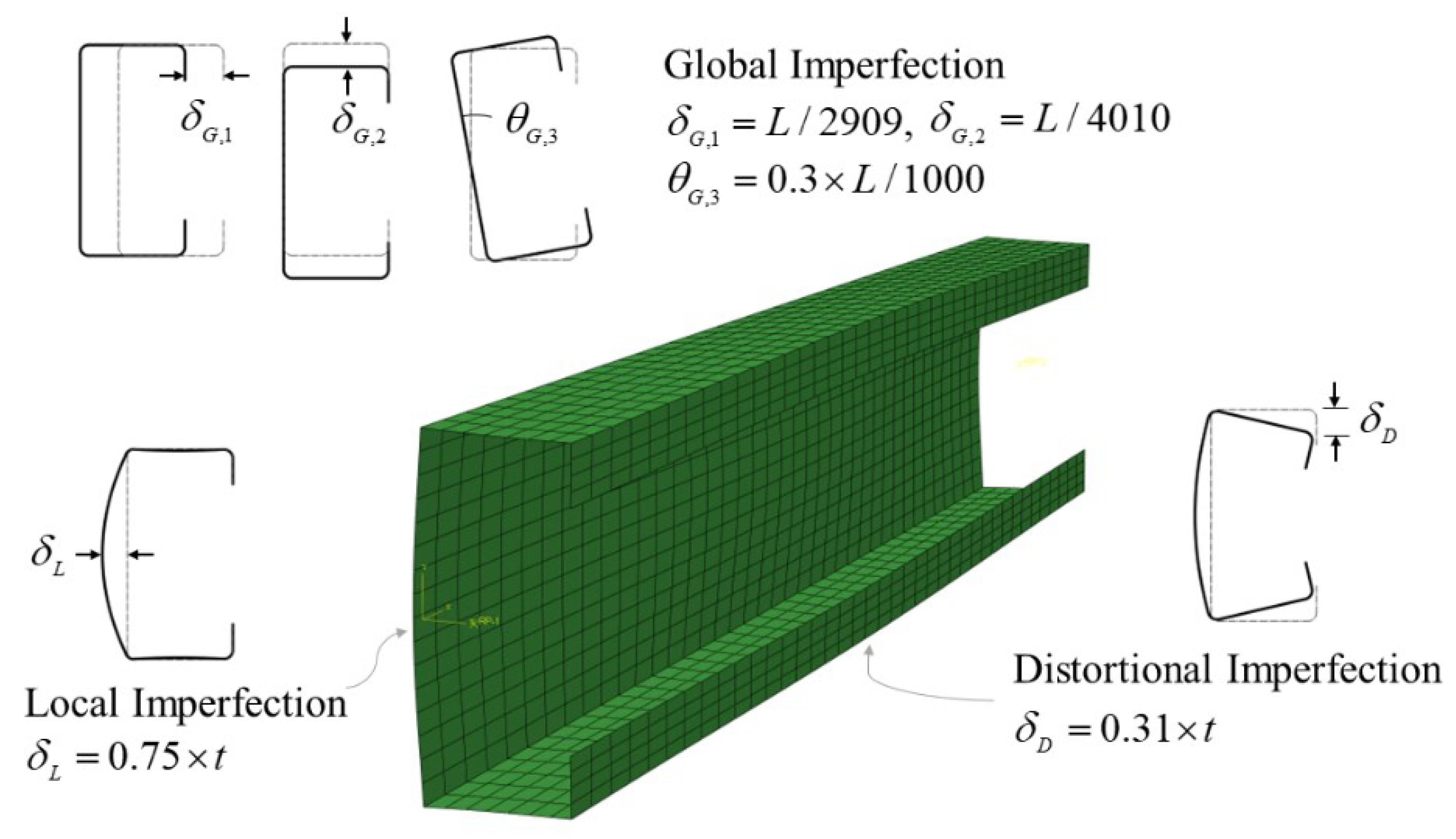
- Geometric imperfections: The initial imperfections are defined according to the one-dimensional spectrum method [45]. For the five initial imperfections in the one-dimensional spectrum method illustrated in Figure 3, based on the existing test results [46], the following amplitudes are adopted: overall buckling imperfection δG,1 = L/2909, δG,2 = L/4010, θG,3 = 0.3 × L/1000; local buckling imperfections δL = 0.75 × t; distortion buckling imperfection δL = 0.31 × t; where L is the member length and t is the cross-section thickness.
- -
- Residual stress: this effect was ignored in the model [47].
Two of the experimental results in [10] was utilized to validate these modeling parameters. Tests in [10] are for conventional steel grade. In [10], the simulation result of the No. 20 medium long column is 63.46 kN against the test result of 63.79 kN, and the simulation result of the No. 18 long column is 48.35 kN against a test result of 49.18 kN. These validated the reliability of the modeling parameters. Hence, with the tested AHSS materials, the same set of modeling parameters were employed in the study.
Figure 1.
Constitutive model and test coupon [48].
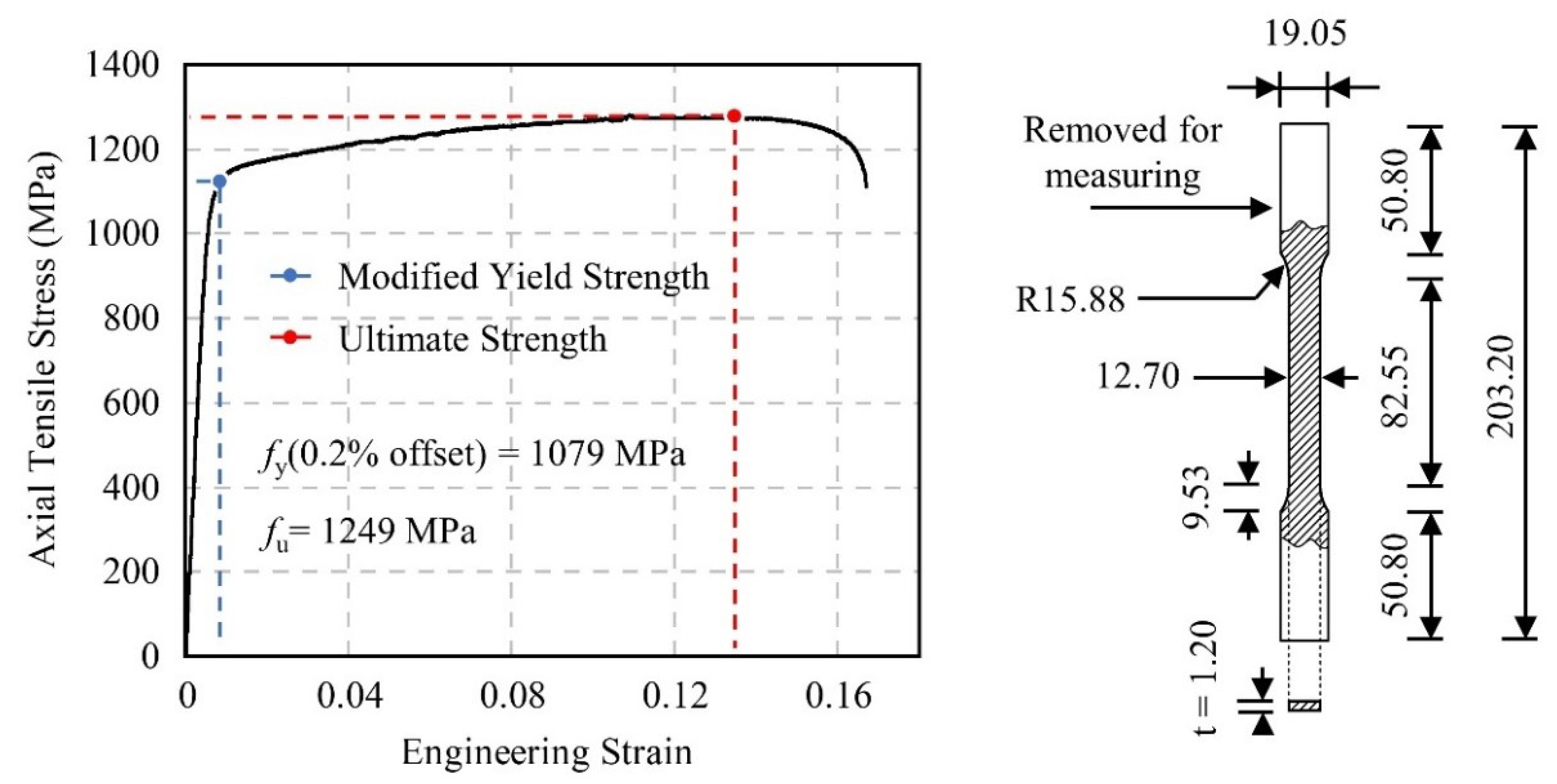
Figure 2.
Details of FE model.
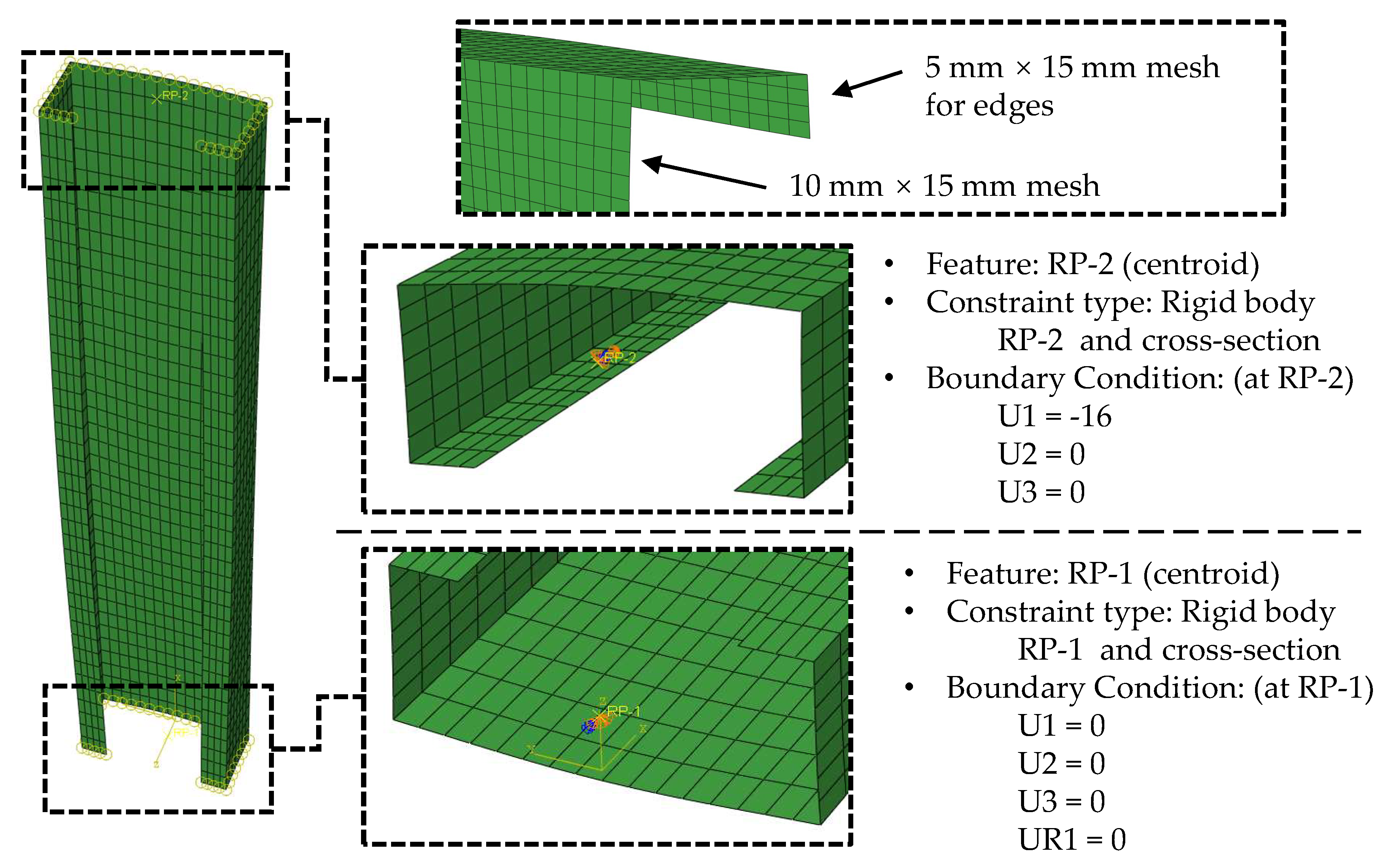
Figure 3.
Initial imperfection definition.
2.2. Modal Analysis
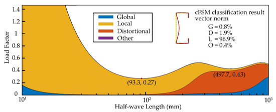
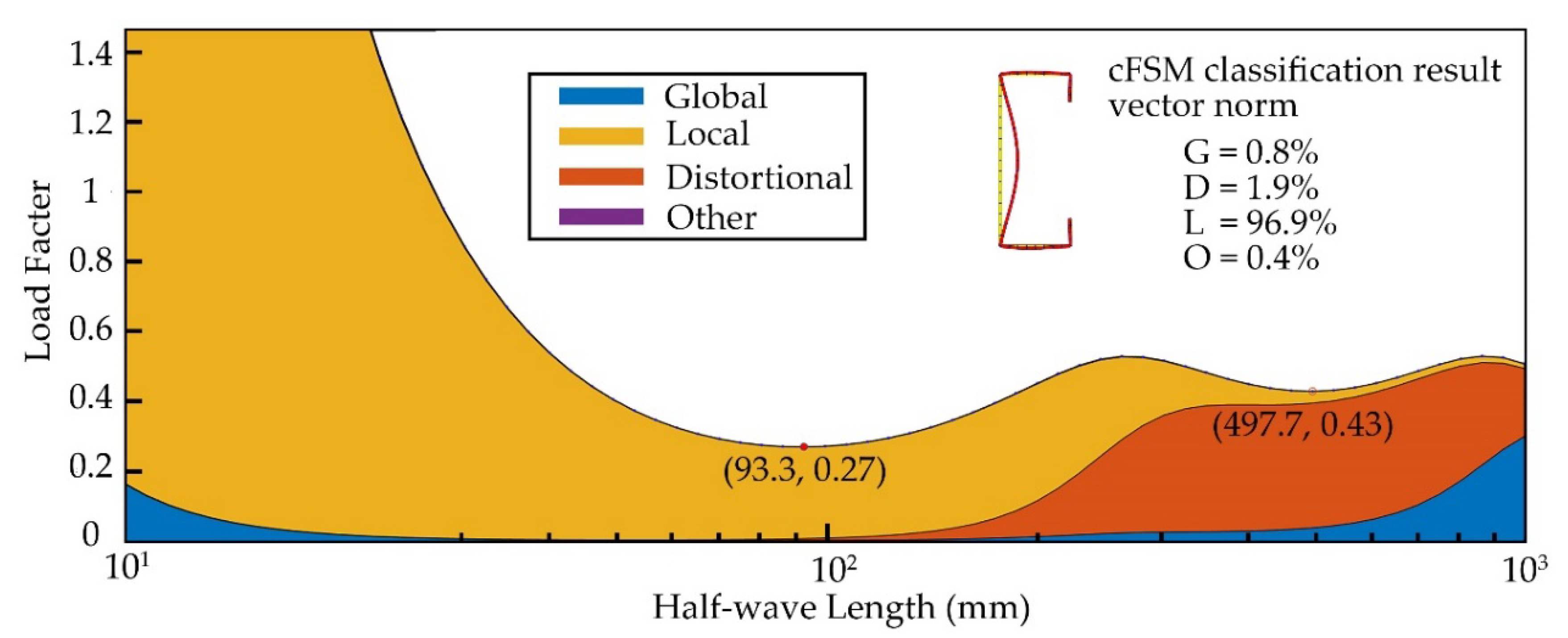
In this study, a typical C cross-section in the CN Code GB50018 was taken as an example, and the elastic buckling mode analysis as shown in Figure 4 was carried out by CUFSM. The modal identification results indicate the participation of the modes. At the local minimum (i.e., 1st local minimum), 96.9% participation is from the local buckling mode and the critical load at here is the lowest (compared to the 2nd local minimum: distortional buckling mode).
Figure 4.
Buckling mode distribution of single member in elastic critical state (member is No.1 cross-section, 2 mm thick, 600 mm long).
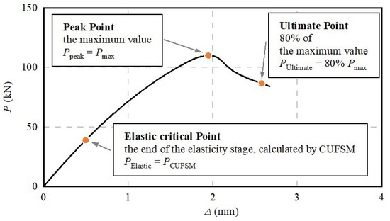
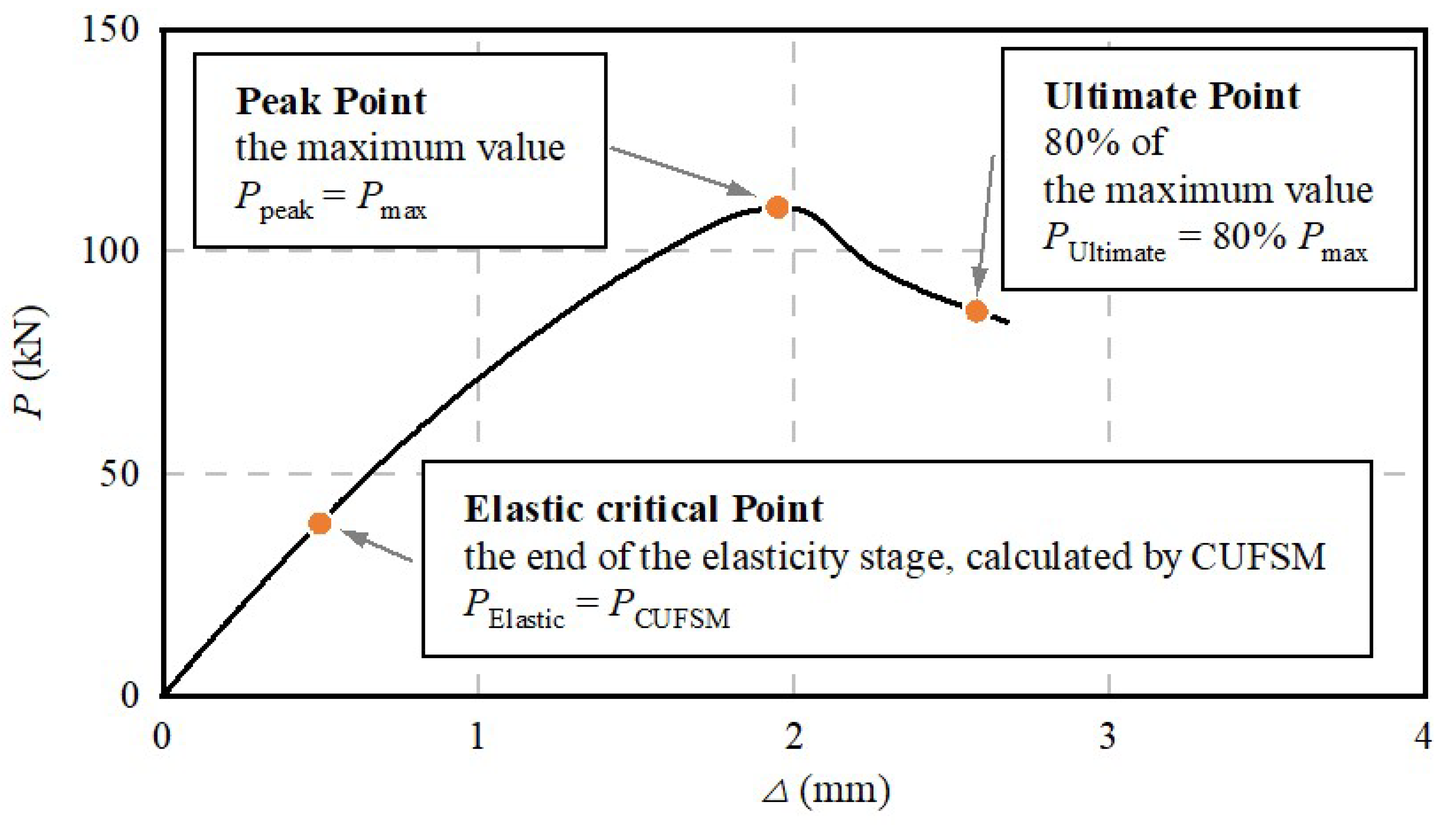
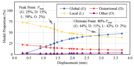
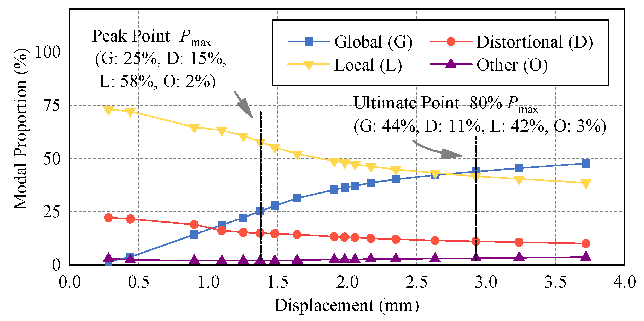
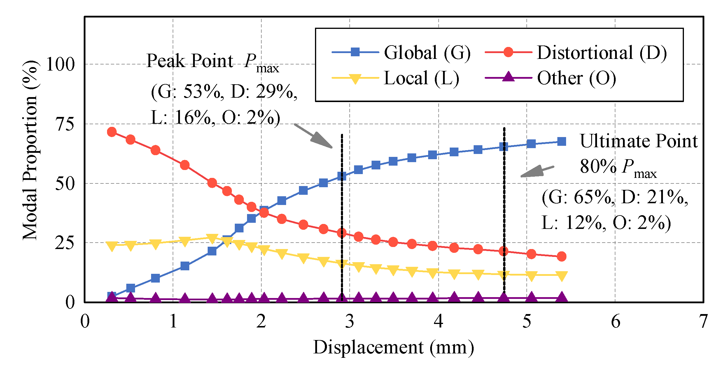
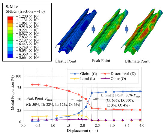
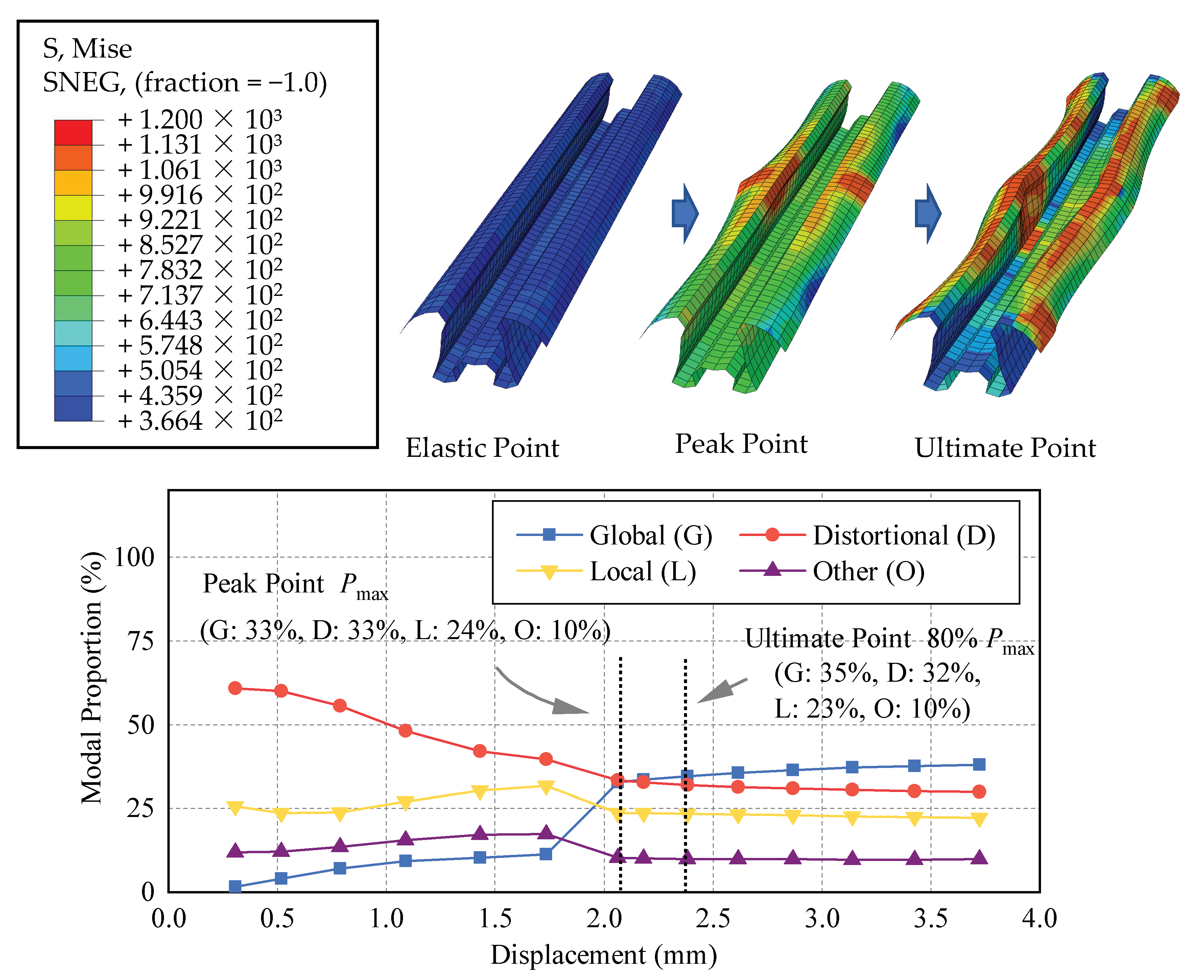
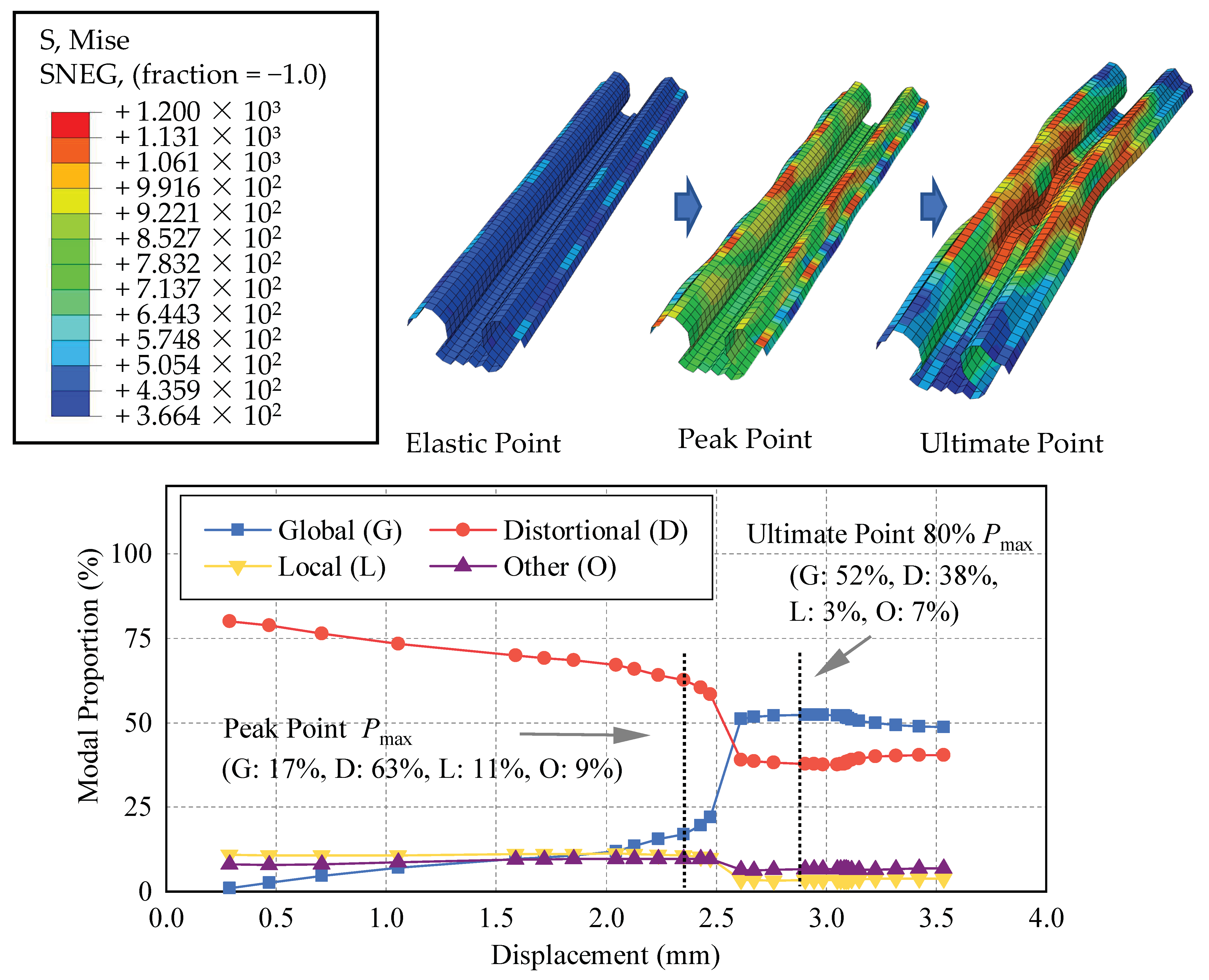
Then, using the modal identification developed by Li et al. [49] the mode participation along the load response curve as shown in Figure 5 could also be identified. The participations are plotted in Figure 6, Figure 7, Figure 8 and Figure 9 (for one section with different member lengths as examples). Three participation values are highlighted in particular: elastic critical point, at peak, and ultimate point, as labeled in Figure 5.
Figure 5.
Schematic diagram of P—Δ curve key points.
Figure 6.
Full range modal participation of member FE simulation (member cross-section parameter is No. 1, 2 mm thick, 300 mm long).
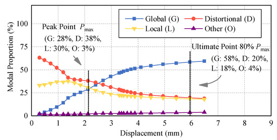
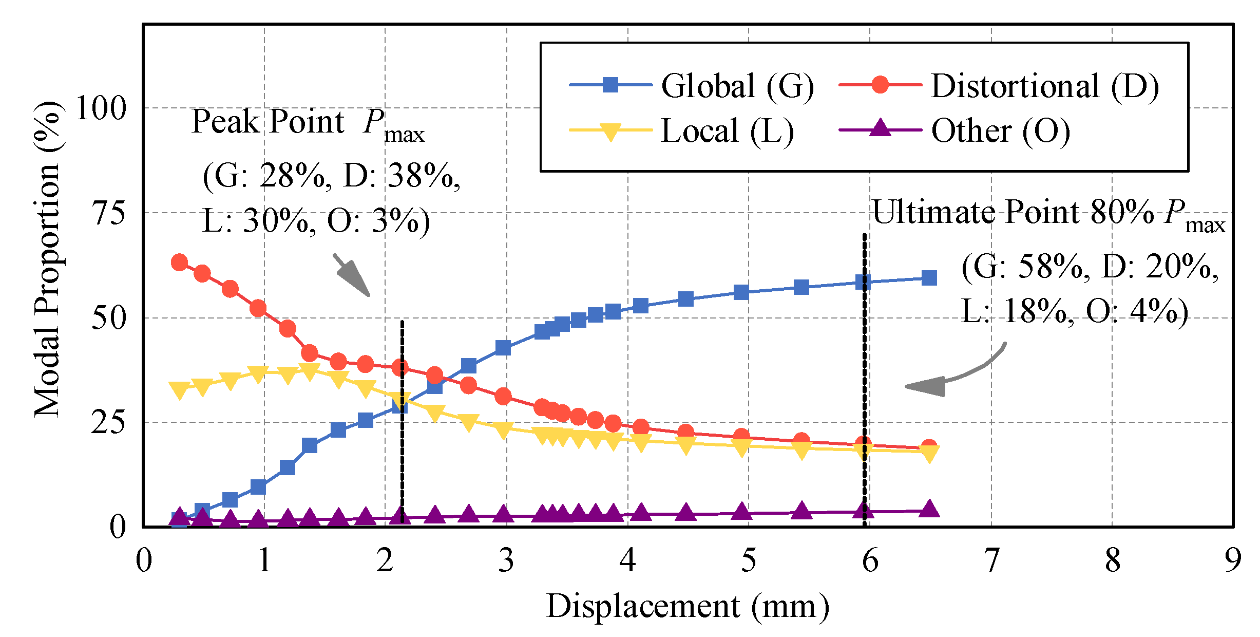
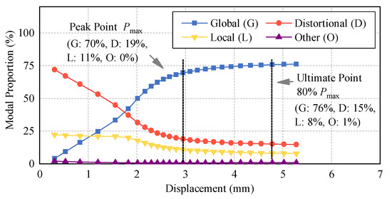
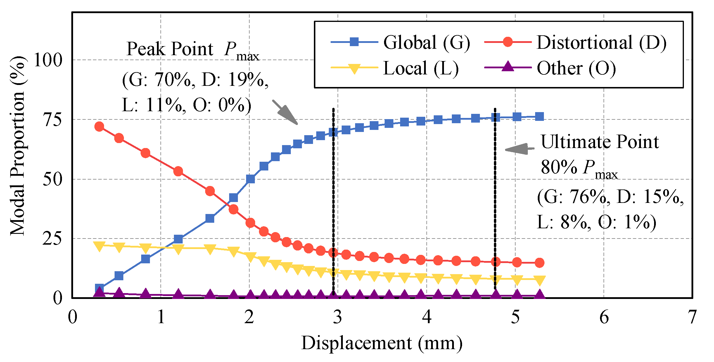
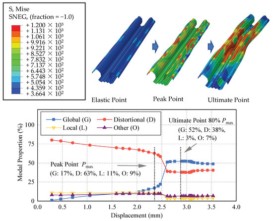
Figure 7.
Full range modal participation of member FE simulation (member cross-section parameter is No.1, 2 mm thick, 600 mm long).
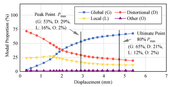
Figure 8.
Full range modal participation of member FE simulation (member cross-section parameter is No.1, 2 mm thick, 900 mm long).
Figure 9.
Full range modal participation of member FE simulation (member cross-section parameter is No.1, 2 mm thick, 1200 mm long).
It can be seen from Figure 6, Figure 7, Figure 8 and Figure 9 that the members with No.1 cross-section have complex mode interaction. For longer members, i.e., 900 and 1200 mm, the failure at peak is dominated by the global mode (very high global participation). Alternatively, for short members such as that of 300 mm, the failure is dominated by local buckling. With a member length of 600 mm, the strong mode interaction along all three modes can be observed and possesses interesting behavior for AHSS sections, due to the high yielding strength, which allows more mode interaction to develop. Hence, the optimization in the study will focus on a member length of 600 mm to allow this interesting phenomenon to happen.
2.3. Limiting Factors of Axial Load Capacity
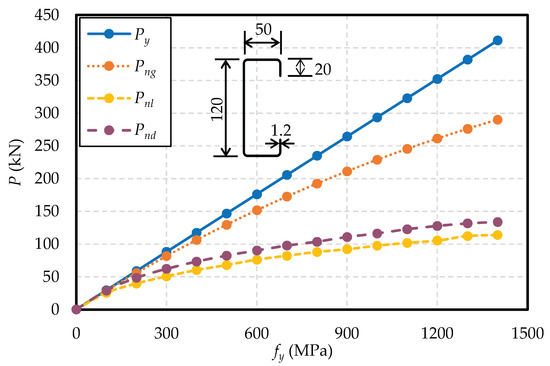
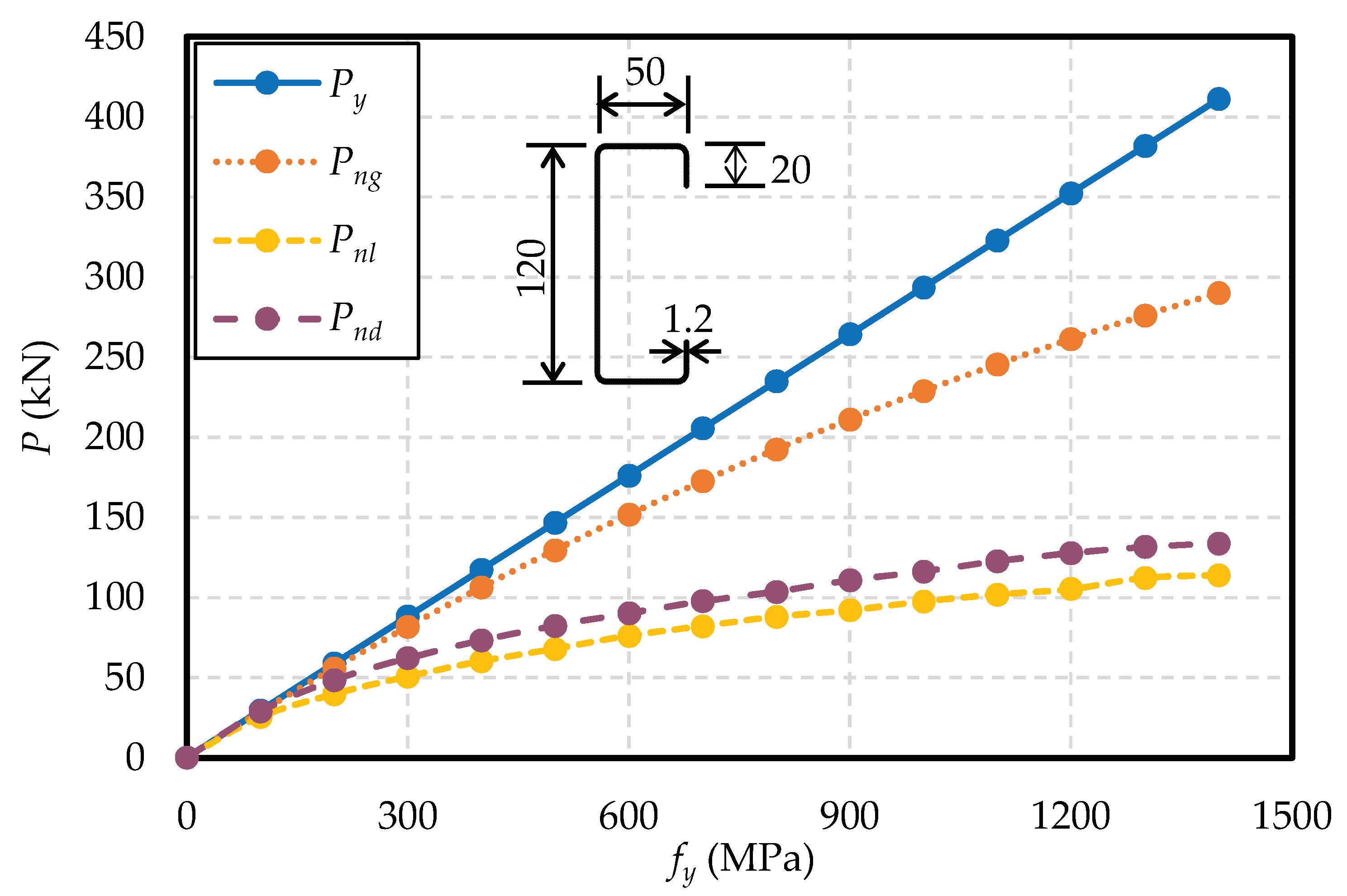
According to the classic formula of DSM [29], when the yield strength fy increases, the slenderness λi (i = g, d, l) of the member will increase, making the corresponding nominal load bearing capacity of each mode decrease, as shown in Equation (1), where Pcrg is the elastic critical load corresponding to the global buckling mode, Pcrl is the elastic critical load corresponding to the local buckling mode, and Pcrd is the elastic critical load corresponding to the distortional buckling mode; Py = Afy is the bearing capacity of the non-weakened member, and Png, Pnl, and Pnd correspond to the nominal bearing capacity of the three basic modes (global, local, and distortion, respectively) of the member.
Although the DSM has not been validated for AHSS sections, the approximate application can still provide significant insight into the material efficiency. Take the member length as 600 mm as selected in Section 2.2. Varying the material’s yielding strength with the section in Figure 10, the nominal axial strength of the section (local, distortional, and global) from the DSM is shown. With the increase in the yielding strength, the axial load strength does not proportionally increase. The axial load strength is greatly limited by the local buckling strength Pnl. Moreover, for this case, the distortional buckling strength is also low and might be controlling for some sections. This indicates the traditional cross-section shape, such as this C-shape, cannot fully take advantage of the high material yielding strength.
Figure 10.
Relationship between material strength and bearing capacity.
3. Construction of Cross-Section Optimization Model
Particle swarm optimization (PSO), a classical neural network optimization algorithm, was used to optimize the cross-section with the highest axial compression bearing capacity as the objective.
3.1. Definition of Free-Form Cross-Section in PSO
According to the classic PSO formula, the algorithm mainly optimizes the particle position in the iterative process. This means that the definition of the particle position is the key to the application of the algorithm, which is to establish a unique corresponding relationship between the particle position and the free-form shape of the cross-section.
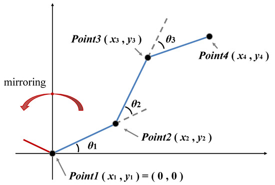
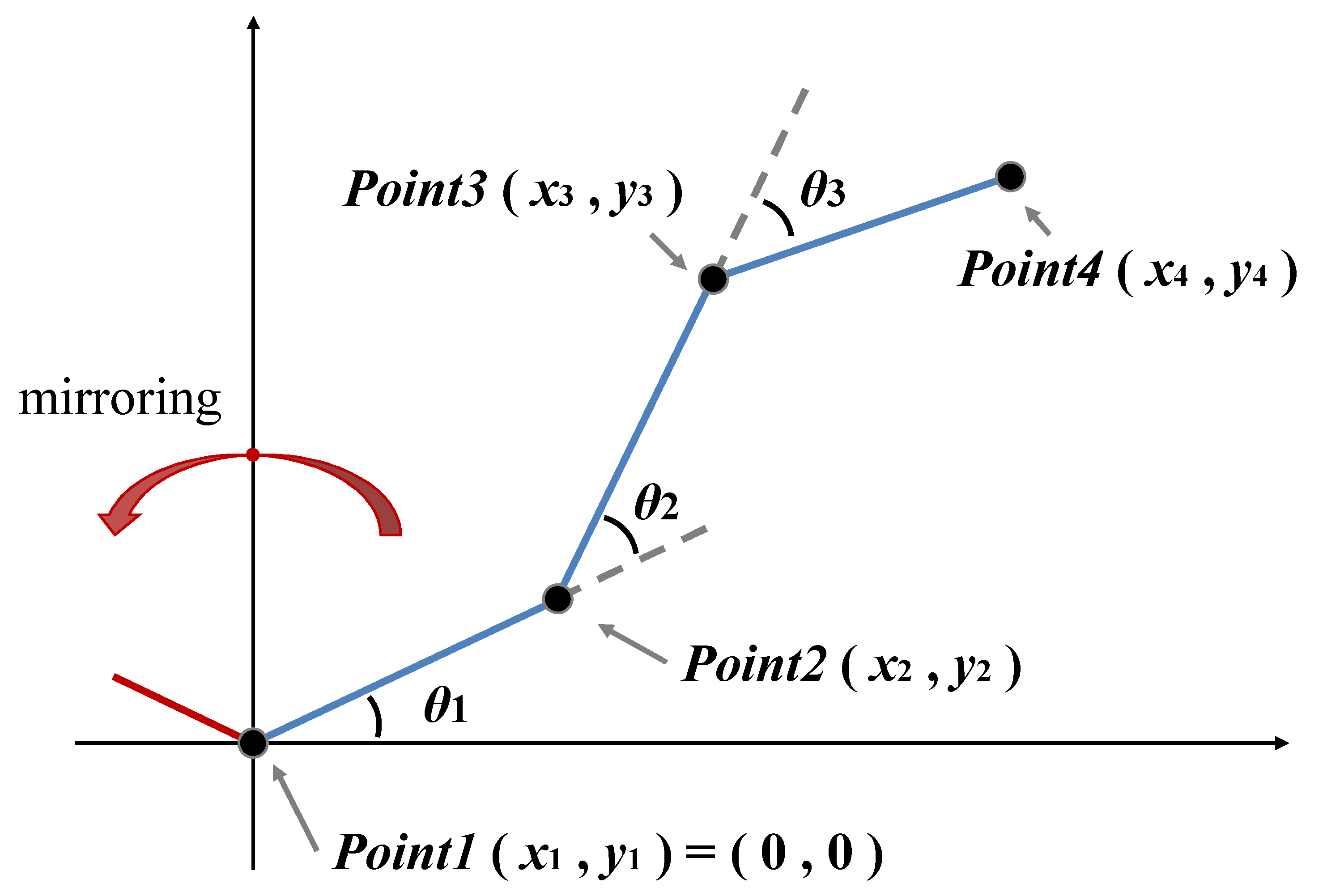
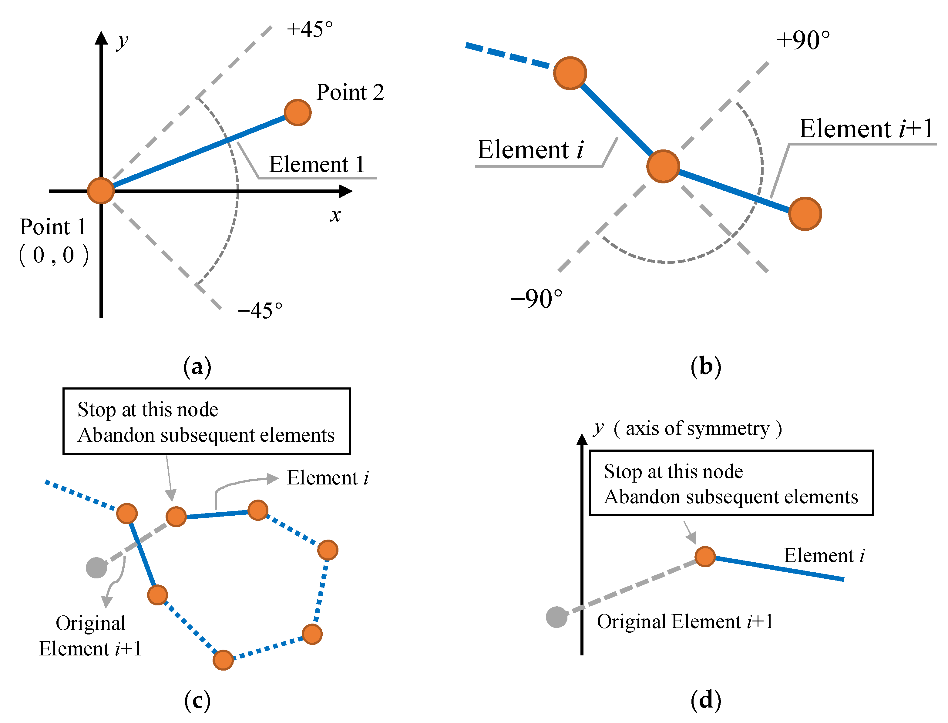
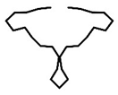
In the most basic definition of PSO, the single particle coordinate is a two-dimensional plane coordinate (x, y). In this paper, its order is raised to produce an n-order coordinate matrix. The n-order coordinate vector is defined as the corner vector of the cross-section. The definition of the free-form cross-section is realized by this n-order rotation vector corner_list. With the coordinate origin (0,0) as the starting point, a free-form shape of the cross-section (polyline) is drawn according to the preset order. Each polyline generates a random corner based on the previous polyline, as shown in Figure 11.
Figure 11.
Generation method of cross-section.
A single particle has a single corner vector corner_list. The generation step of a single particle is repeated m times to obtain the optimized object of PSO, a complete particle swarm, which also represents m random cross-section segments. This particle swarm is presented as a rotation matrix corner_matrix in this algorithm. The node coordinate matrix point_list and element matrix element_list of the segment can also be obtained, as shown in the following formula:
where corner_list is the nth order rotation vector, corner_matrix is the m × n order rotation matrix, point_list is the nth order rotation vector, point_matrix is the m × n order rotation matrix, θj is the relative angle of the j-th element in the j-1 element, θsum,i is the total angle of the i-th element, that is, the angle between the i-th element and the x-axis; x1 and y1 represent the coordinates of the starting (origin) point; xi and yi represent the coordinates of the second node; len_elemt represents the length of a single element.
In addition to the above basic definitions, two conditions are imposed to enhance the uniqueness of the relationship between the corner matrix and the cross-section shape: (1) The definition of uniaxial symmetry is added to the cross-section type. If the axis of symmetry is set as x = 0, the free folded line segment will expand on the right side of the axis of x = 0 and the complete cross-section will be obtained by folding. (2) The length of each element len_elemt is fixed and the cross-section has an equal length and is a multi-section broken line.
3.2. Objective Function and Constraint Conditions
The definition of the objective function is another key to the application of the PSO algorithm to the optimization in this paper. It has certain universality for PSO classical application, and the difference is mainly in the process of optimization calculation. The process begins with the introduction of the corner matrix into the algorithm model and ends with the derivation of the bearing capacity of the member. After the PSO iteration module generates a set of corner matrices, the objective calculation steps can begin. The corner matrix is used to generate a unique corresponding cross-section fold, which also corresponds to a unique node matrix and an element matrix. In this paper, a simple CUFSM calculation platform, which can be docked with PSO, was built using MATLAB software. After the input of the node and element matrices, the calculation of the constrained finite strip method can be realized by matching with other pre-defined conditions, such as material parameters. Consistent with the conventional CUFSM calculation, the output of the simple calculation platform is mainly the load characteristic curve along the half-wavelength of the member. The load characteristic values independently corresponding to each mode in the curve are extracted, and then the elastic critical loads corresponding to each mode are calculated.
The modal slenderness ratio can be calculated from the critical elastic load, and the calculation enters the DSM step. The buckling bearing capacity of members calculated by the DSM formula is defined as the objective function and participates in the optimal particle comparison in PSO iteration, as shown in Equations (8)–(11):
The objective function in this paper is essentially the buckling bearing capacity of members calculated by the DSM. Unlike the classical DSM method, which takes the minimum nominal bearing capacity, the optimum selection in this paper seeks to balance the nominal bearing capacity. Based on the principle of DSM, this method avoids the problem that the cross-section can easily induce local or distorted buckling; thus, the single nominal bearing capacity is too small. By suppressing the coupling of L or D or L-D, the buckling mode coupling effect can be considered more comprehensively.
In addition to the above process, in order to cater to the actual process conditions of CFS, some additional constraints are also set in the part of generating the corner list. According to the definition of the free-form cross-section based on the PSO algorithm, the foundation free-form cross-section can be created and the subsequent optimization iteration can be achieved. However, the degree of freedom of the cross-section generated by this method is too high, and it is easy to have excessive corner and knotting of the segment itself. The object of optimization is a uniaxial symmetric cold-formed thin-walled open member, whose cross-section has certain conditions. Four constraint conditions for cross-section creation are defined to ensure that the optimization results of the algorithm conform to the characteristics of actual members and are suitable for industrial production. The restrictions mainly include two points:
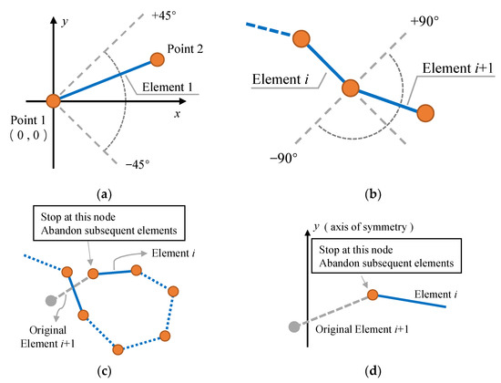
- (1)
- The included angle between two adjacent elements shall not be less than 90°. Since the free-form shape of the cross-section in this paper is the complete cross-section obtained by first forming the polyline on the right side of the y-axis, and then mirror folding the y-axis, the first element needs to meet the state shown in Figure 12a, so as to meet the requirement that the included angle between element1 and the folded element is not less than 90°. For other elements, the included angle of adjacent elements shall not be less than 90° according to the restrictions in Figure 12b. The code for this condition in optimization is shown as Equation (12), where θ1 is the corner of the first element, and θi (i = 2, 3, 4, …) is the corner of the subsequent elements:Figure 12. Constraints on the free-form shape of cross-section. (a) The included angle between element1 and the folded element is not less than 90°; (b) The included angle of adjacent elements shall not be less than 90° according to the restrictions; (c) The member element itself does not cross and tie; (d) The self-inter cross-section of the complete cross-section will also occur.
- (2)
- The member element itself does not cross and tie, as shown in Figure 12c. Note that since the cross-section is a complete cross-section obtained by folding the mirror image of the y-axis, if the one-sided cross-section intersects the y-axis of the symmetry axis, the self-inter cross-section of the complete cross-section will also occur, as shown in Figure 12d, which also needs to be avoided. The code for this condition in optimization is shown as Equations (13) and (14), where xi is the abscissa of the point, (xm, ym) and (xm+1, ym+1) are the end-node coordinates of the m-th element, (xn, yn) and (xn+1, yn+1) are the end-node coordinates of the n-th element, f(x, y) is the functional expression of the m-th element:
3.3. Optimizing Processes and Parameters
The PSO algorithm determines the trajectory of particles through three factors, namely, global optimum, individual historical optimum, and velocity inertia of particles themselves. After particle generation and definition of the objective function, it can be optimized iteratively according to established rules. Equations (15) and (16) are the classical formulas of PSO, which means that the i-particle of the particle group moves in three directions, superimposing the actual direction of motion and producing the position of the i-particle in the k + 1 wheel under the influence of the group optimum position, individual optimum position, and speed inertia of the last wheel:
where k is the iteration cycle; V is the particle velocity; X is the particle coordinate, which is n-order corner_list; Pgdk represents the optimum particle in the k-th population, which has the largest objective in the k-th population data; Pidk represents the individual optimal particle of the kth round, which is the largest corner_list selected from the historical data of particle i in the first k rounds; Vidk+1 is the motion speed of particles in the k + 1 round; w is the inertial coefficient, indicating that the speed of the previous wheel will have a certain influence on this wheel; c1 and c2 are two independent random constants within 0~1, which randomly weaken the influence of group optimum and individual optimum, and increase the uncertainty of particle motion; r1 and r2 are acceleration coefficients, or learning factors. r1 is an individual learning factor, and r2 is a group learning factor. Their effects are similar to those of c1 and c2. The difference is that the learning factors are not randomly generated and are manually designated to directly control the influence of groups and individuals on particles; Xidk is a single particle, the position coordinate of the i-th particle of the particle swarm in the k-th round; Xidk+1 is the position coordinate of the i-th particle of the particle swarm in the k + 1 round.
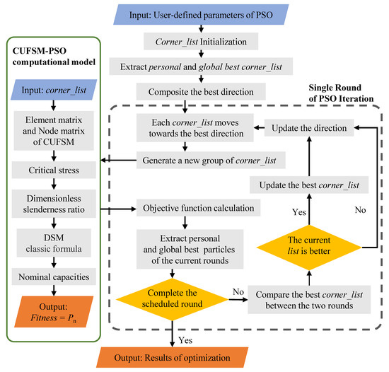
The single round iteration of PSO is completed by executing all corner_list in the particle swarm in Equations (15) and (16) once. When the number of iterations reaches the preset value, the iteration is stopped for subsequent convergence check and data collection. The complete algorithm flow is shown in Figure 13. See Table 1 for all parameters used in this document and their descriptions.
Figure 13.
PSO algorithm flow chart.
Table 1.
PSO parameter definition.
4. Optimization Results and FE Verification
Three groups of optimizations were carried out to explore the optimization of the AHSS cross-section. The optimization object is a medium-length column with a length of 600 mm. The thickness of the plate is 1.2 mm, which is consistent with the raw material parameters of the material property test. The plates with total lengths of 260, 300, and 340 mm were used for optimization. The three optimization groups were named FS260, FS300, and FS340.
4.1. Optimization Path and Optimization Result
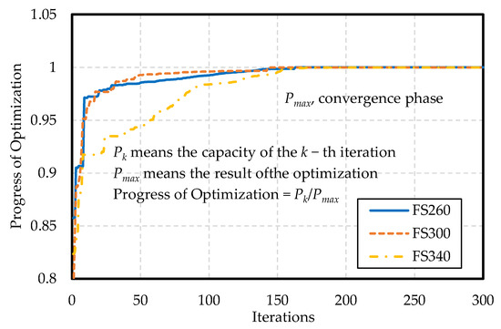
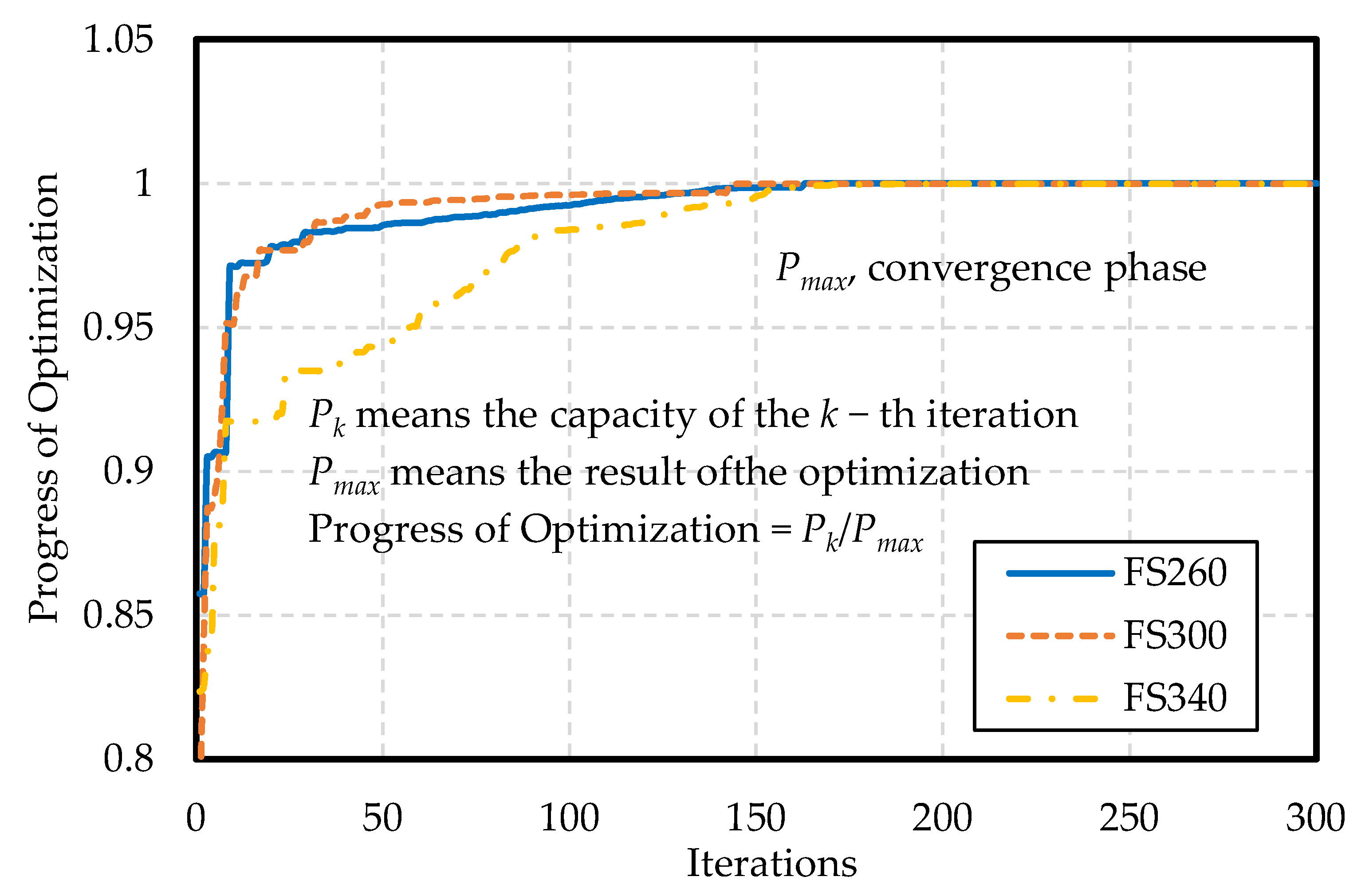
During the execution of the PSO algorithm, the single-step optimal cross-section can be output in each iteration step, so the optimization history path shown in Figure 14 is summarized. The ordinate is the optimization progress, the ratio of the optimal bearing capacity of each generation to the final optimization result, and finally tends to 1. The abscissa is an iterative algebra. The three groups of optimizations reached the maximum value in a single group in the 150–200 generations, and did not change in the subsequent 100 generations, achieving convergence.
Figure 14.
PSO history path.
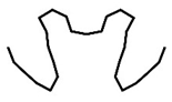
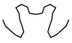
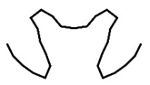
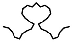
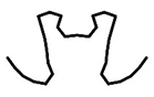
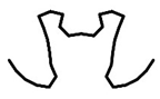
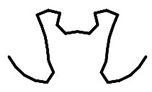
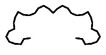
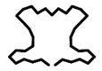
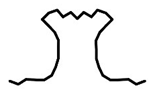
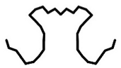
From Figure 14, the optimization of fixed time nodes was selected, and the cross-section shape is shown in Table 2. Starting from the first generation, the table records the optimal cross-section of the current particle swarm every 75 rounds. Among them, the cross-section of the first generation is completely random, and in the 75th and 150th generations, there is a clear trend of cross-section optimization, evolving to a cross-section similar to the shape of Ω. In the 225th generation, all three groups of optimizations achieved convergence, so the cross-section at this time was the optimization result.
Table 2.
Summary of cross-section optimization process.
4.2. FE Verification
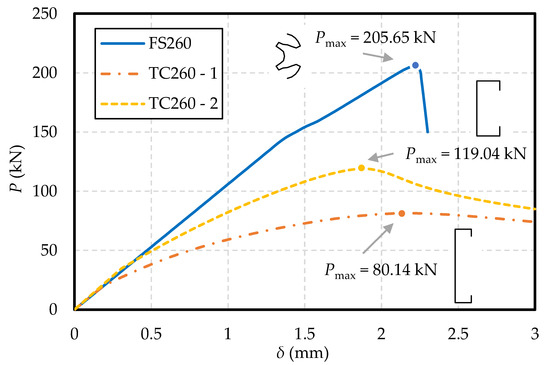
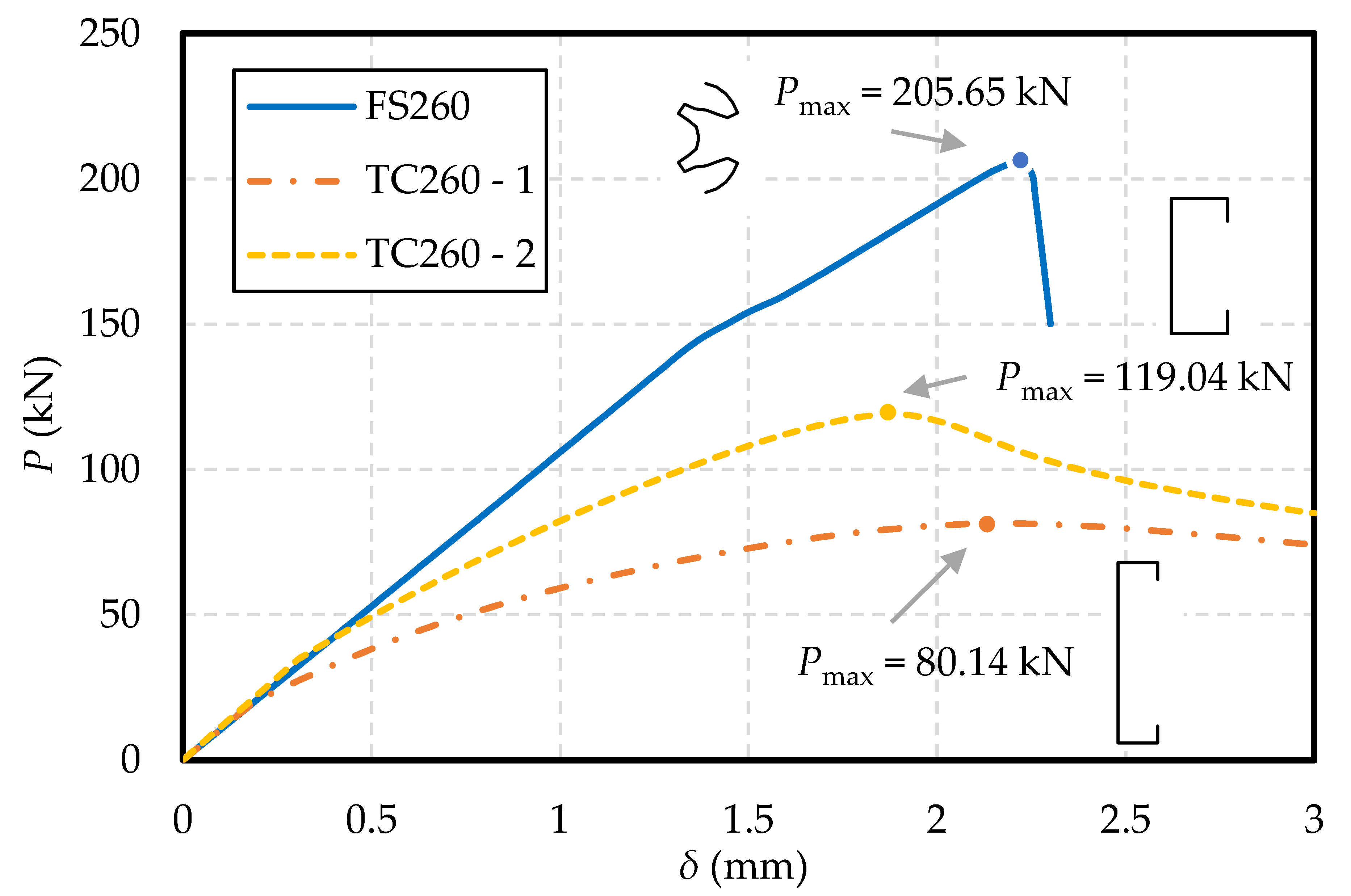
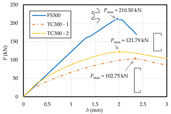
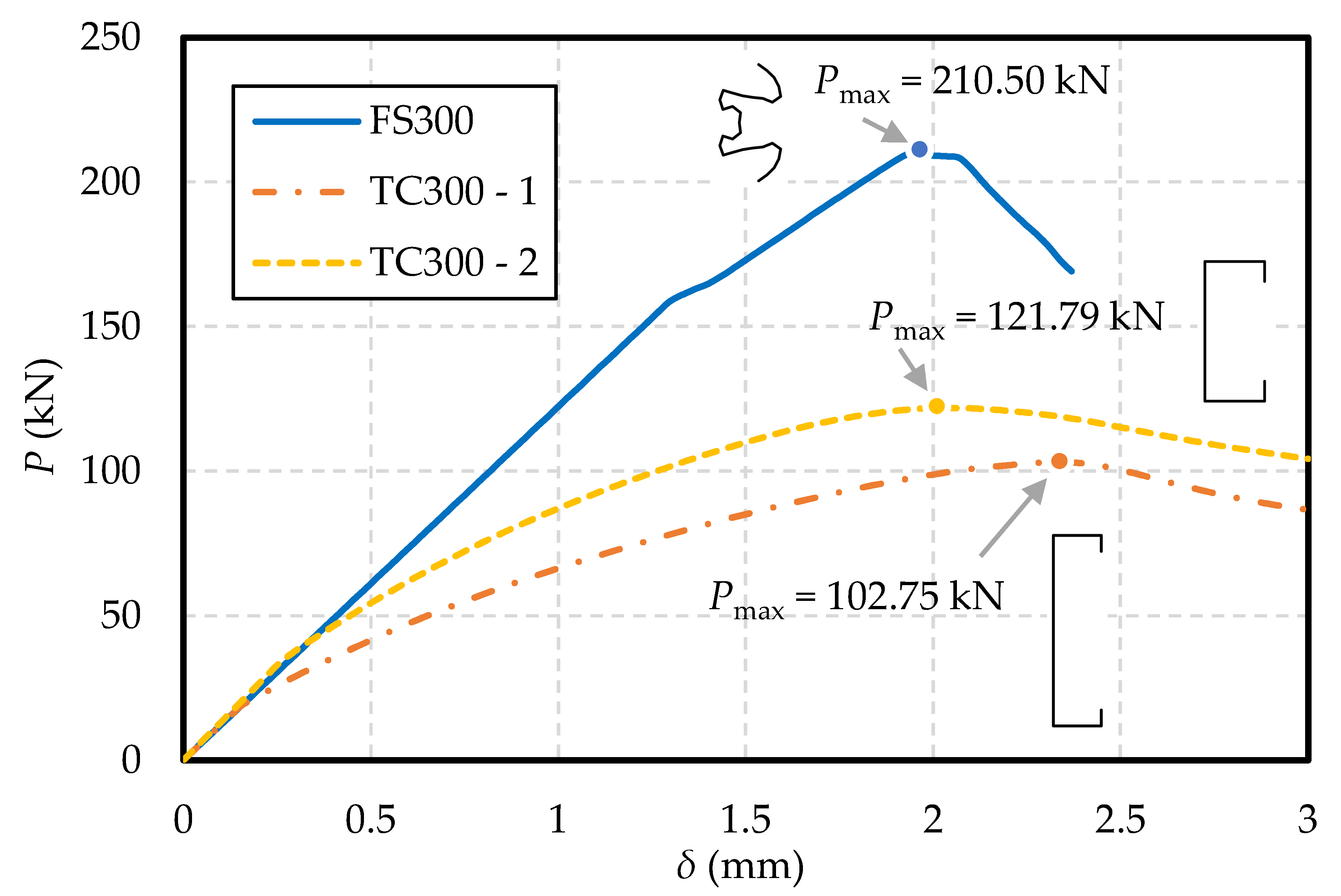
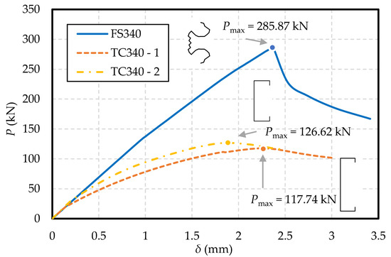
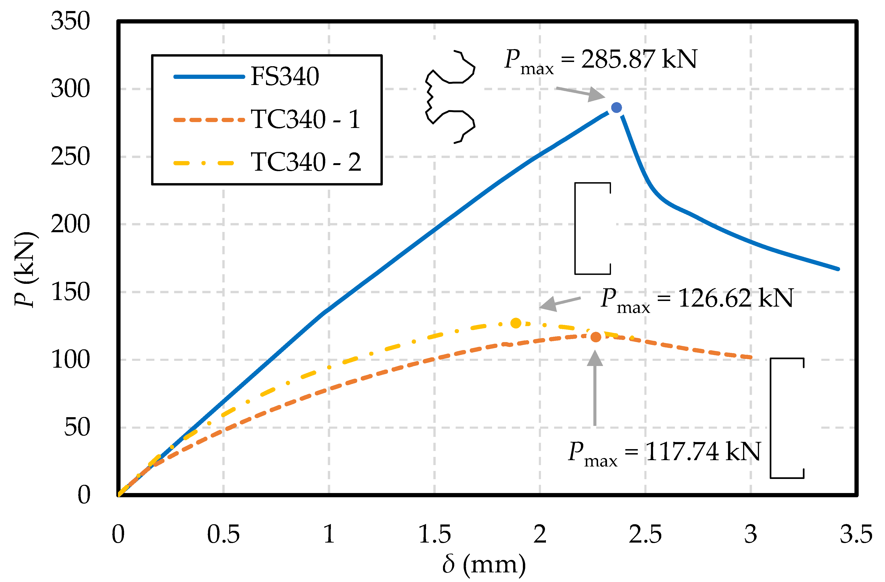
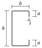
The optimized cross-section and its corresponding bearing capacity were calculated using CUFSM and DSM. Further verification was required in combination with FE simulation. The establishment method of the FE model is the same as that in Section 2.1. The three groups of load displacement curves and the buckling state of the members simulated and summarized are shown in Figure 15, Figure 16 and Figure 17. In order to reflect the difference between the free-form shape of the cross-section optimized in this paper and the traditional cross-section, two traditional C cross-sections were added to each optimization group for comparative calculation under the same conditions. Traditional C cross-sections for comparison are shown in Table 3, where TC260-1, TC300-1, and TC340-1 (traditional C cross-section) are the initial cross-section forms in the literature [30], and TC260-2, TC300-2, and TC340-2 are the standard C cross-sections in CN code GB50018 [52]. The member length is 600 mm, and the cross-section thickness is 1.2 mm. The cross-section area and cross-section thickness in a single control group are consistent.
Figure 15.
FS260 FE results.
Figure 16.
FS300 FE results.
Figure 17.
FS340 FE results.
Table 3.
Parameters of C cross-section.
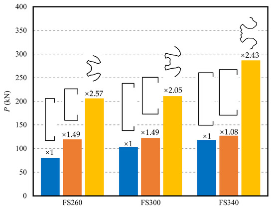
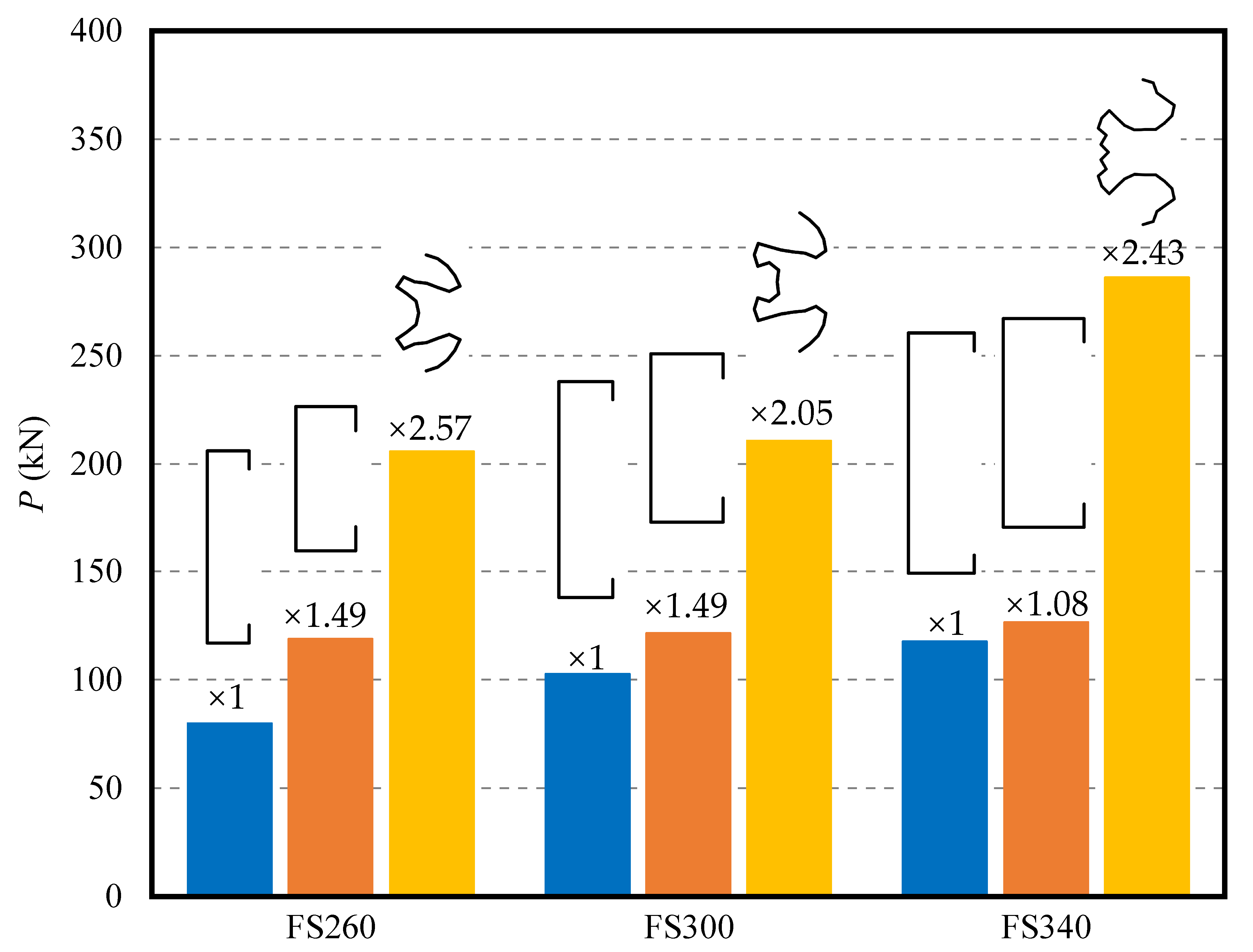
The optimization results are calculated and verified in Section 4.1 and Section 4.2, and it is preliminarily believed that the optimization in this paper has certain reliability. It can be seen from Figure 15, Figure 16, Figure 17 and Figure 18 and Table 4 that:
Figure 18.
Summary of optimized relative values.
Table 4.
Comparison between PSO and FE results.
- (1)
- The bearing capacity results of FE simulation are basically consistent with those of PSO optimization.
- (2)
- The PSO-CUFSM in this paper has a remarkable effect. For the free-form shape of cross-sections of FS260, FS300, and FS340, the maximum bearing capacity can be increased by 2.57, 2.05, and 2.43 times, respectively, effectively improving the material utilization of AHSS members.
4.3. Modal Verification
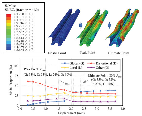
The three groups of free-form cross-sections FS260, FS300, and FS340 were analyzed by modal classification, and the modal participation of each FE analysis step was extracted. The extraction method is the same as in Section 2.2. The participation of each group of members is shown in Figure 19, Figure 20 and Figure 21.
Figure 19.
Full range modal participation of FS260.
Figure 20.
Full range modal participation of FS300.
Figure 21.
Full range modal participation of FS340.
For AHSS members, the elastic critical stress of local buckling is too low when the traditional cross-section is used. Furthermore, the coupling of local buckling and distortional buckling has a limiting effect on the bearing capacity of members.
In Figure 19, Figure 20 and Figure 21, the local modal participation of the optimized cross-section is lower than that of the traditional C cross-section (Section 2.2). In this way, the premature occurrence of local buckling is restrained, and the local–distortional coupling induced by local buckling is avoided, thus effectively improving the bearing capacity of members.
5. Discussion
The main purpose of this study was to explore the PSO-DSM cross-section shape optimization method for AHSS members. Through modal analysis and FE simulation, the feasibility of the optimization method was confirmed, and the shape optimization of Q&P1180 material was carried out.
First, the modeling parameters of this study were validated using a conventional steel grade. More validation dedicated directly to AHSS members is necessary. Some of the modeling parameters, such as the residual stresses, warrant additional study given the high yielding strength of AHSS. The residual stress pattern and magnitude, and its impact on strength, are worth more studies given the limited available studies.
Second, the optimization method developed in this study demonstrates excellent feasibility for a wide range of section optimization using AHSS. Given the wide range of AHSS grades, optimization across these steel grades would be an interesting future study. The different section profiles the optimization may yield would be of significant interest.
Third, the optimization in this study is termed free-form optimization. In terms of manufacturing, only certain limitations of turn angles to avoid self-knotting were considered, and many practical constraints were not fully considered. Hence, the optimal shapes from this study are too complex to manufacture (or would be too costly to manufacture). In future studies, more manufacturing constraints, including connection concerns, will be added to seek a balance between performance and manufacturability.
6. Conclusions
In this study, the free-form shape optimization of AHSS columns was examined. Modal analyses from CUFSM and the FE method illustrate the complex mode interaction potentials for AHSS sections due to the material’s high yielding strength. Then, a feasible optimization member was identified as 600 mm to accommodate the potential interesting interaction among modes. The free-form shape optimization method using the PSO algorithm along with the numerically implemented DSM was established to conduct three groups of optimizations with a varying total length (i.e., material). The optimization provides promising optimal shapes. Their strengths were validated further using the nonlinear FE models given the drawbacks in the DSM regarding the application of AHSS members. The following conclusions can be drawn:
- (1)
- Through nonlinear FE modal identification and classification, it can be seen that the critical stress of the local buckling (L) of the traditional cross-section is low; hence local buckling (L) occurs early, and the interaction with distortional buckling (D) limits the bearing capacity. The optimized cross-section restrains the early occurrence of (L), reduces the coupling effect of local buckling (L) and distortional buckling (D), and thus improves the bearing capacity.
- (2)
- The proposed PSO-DSM method shows promising optimal results, although the DSM was only approximately applied to AHSS sections. Based on the further validation with nonlinear FE results, for the three groups of optimizations, the load bearing capacity was increased by 2.57, 2.05, and 2.43 times, respectively, compared to that of the traditional cross-sections.
- (3)
- The free-form shape optimization mainly restricts the local buckling in the optimization direction. The three groups of optimized cross-sections are similar, and the optimized cross-sections all have web stiffeners, a flange bending inward, and a large area curling outward. In this study, it is defined as “a cross-section similar to Ω shape”.
Overall, in this study, the AHSS cross-sections were demonstrated to have significant potential to maximize the material efficiency. The optimized shapes in this study have excellent load-carrying capacity but may suffer significantly in terms of manufacturability.
Author Contributions
Conceptualization, L.Y., Y.N. and Z.L.; methodology, L.Y., T.D. and Z.L.; software, T.D.; validation, L.Y.; formal analysis, T.D.; investigation, Y.N.; resources, T.D.; data curation, T.D.; writing – original draft, T.D. and Y.N.; writing – review & editing, L.Y. and Z.L.; visualization, Y.N.; supervision, L.Y.; project administration, L.Y.; funding acquisition, L.Y. All authors have read and agreed to the published version of the manuscript.
Funding
This research was funded by National Natural Science Foundation of China grant number 52278150 and Central Government for Local Science and Technology Development of Tibetan Autonomous Region grant number XZ202201YD0032C.
Data Availability Statement
The data are available upon request from the corresponding authors.
Acknowledgments
The research was sponsored by the National Natural Science Foundation of China (Grant No. 52278150), the Project of Central Government for Local Science and Technology Development of Tibetan Autonomous Region (Grant No. XZ202201YD0032C).
Conflicts of Interest
The authors declare no conflict of interest.
References
- Hancock, G.J. Cold-formed steel structures. J. Constr. Steel Res. 2003, 59, 473–487. [Google Scholar] [CrossRef] [Scilit]
- Li, Y.; Huang, B. Research on load-bearing performance of new fabricated steel structure beam-column joints with energydissipating elements. Structures 2022, 38, 492–501. [Google Scholar] [CrossRef] [Scilit]
- Wang, J.; Zhou, T.; Wu, H.; Guan, Y.; Zhang, L. Cyclic performance of steel frame fabricated with cold-formed steel composite wall structure. Eng. Struct. 2022, 270, 114892. [Google Scholar] [CrossRef] [Scilit]
- Yang, H.; Wang, H.; Qian, H.; Jin, X.; Chen, D.; He, Y.; Li, Q.; Fan, F. Mechanical performance of pre-engineered closed section beam-column connections in CFS frames: Experimental investigation. Structures 2022, 39, 164–174. [Google Scholar] [CrossRef] [Scilit]
- Zhang, Z.-W.; Bai, G.-L.; Qin, C.-G.; Li, J.-R.; Liu, H.-Q. Shaking table test of fabricated concrete shear wall structure and study on damage mechanism of strong earthquake. Structures 2022, 43, 645–656. [Google Scholar] [CrossRef] [Scilit]
- Dar, M.A.; Subramanian, N.; Anbarasu, M.; Ghowsi, A.F.; Arif, P.A.; Dar, A. Testing and FE simulation of lightweight CFS composite built-up columns: Axial strength and deformation behaviour. Thin-Walled Struct. 2021, 167, 108222. [Google Scholar] [CrossRef] [Scilit]
- Sangeetha, P.; Vaishnavi, M.; Modhagapriyan, A.; Rajarajan, T. Effect of batten plates on the unlipped channel CFS built- up column under axial compression. Mater. Today Proc. 2022, 66, 1796–1804. [Google Scholar] [CrossRef] [Scilit]
- Rajanayagam, H.; Upasiri, I.; Poologanathan, K.; Gatheeshgar, P.; Sherlock, P.; Konthesingha, C.; Nagaratnam, B.; Perera, D. Thermal Performance of LSF Wall Systems with Vacuum Insulation Panels. Buildings 2021, 11, 621. [Google Scholar] [CrossRef] [Scilit]
- Naser, M.; Degtyareva, N. Temperature-induced instability in cold-formed steel beams with slotted webs subject to shear. Thin-Walled Struct. 2019, 136, 333–352. [Google Scholar] [CrossRef] [Scilit]
- Torabian, S.; Zheng, B.; Schafer, B.W. Experimental response of cold-formed steel lipped channel beam-columns. Thin-Walled Struct. 2015, 89, 152–168. [Google Scholar] [CrossRef] [Scilit]
- Hasanali, M.; Mojtabaei, S.M.; Clifton, G.C.; Hajirasouliha, I.; Torabian, S.; Lim, J.B. Capacity and design of cold-formed steel warping-restrained beam-column elements. J. Constr. Steel Res. 2022, 190, 107139. [Google Scholar] [CrossRef] [Scilit]
- Anbarasu, M.; Dar, M.A. Axial capacity of CFS built-up columns comprising of lipped channels with spacers: Nonlinear response and design. Eng. Struct. 2020, 213, 110559. [Google Scholar] [CrossRef] [Scilit]
- Singh, R.; Samanta, A. Numerical finite element simulation and structural behaviour of cold-formed steel members. Mater. Today Proc. 2022, 65, 3300–3305. [Google Scholar] [CrossRef] [Scilit]
- Li, Y.; Zhou, T.; Zhang, L.; Ding, J.; Zhang, X. Distortional buckling behavior of cold-formed steel built-up closed section columns. Thin-Walled Struct. 2021, 166, 108069. [Google Scholar] [CrossRef] [Scilit]
- Defining Steels-AHSS Guidelines. 10 October 2021. Available online: https://ahssinsights.org/metallurgy/steel-grades/ (accessed on 10 October 2021).
- Srivastava, A.K.; Patra, P.K.; Jha, R. AHSS applications in Industry 4.0: Determination of optimum processing parameters during coiling process through unsupervised machine learning approach. Mater. Today Commun. 2022, 31, 103625. [Google Scholar] [CrossRef] [Scilit]
- Yang, H.; Wang, H.; Yang, Z.; Huang, Y.; Li, D.; Peng, Y.; Wu, P. In situ neutron diffraction and crystal plasticity analysis on Q&P1180 steel during plastic deformation. Mater. Sci. Eng. A 2021, 802, 140425. [Google Scholar]
- Sedaghat-Nejad, R.; Shahverdi, H.R.; Askari-Paykani, M. Introduction and mechanical evaluation of a novel 3rd-generation medium manganese AHSS with 86 GPa% of PSE. Mater. Sci. Eng. A 2022, 843, 143104. [Google Scholar] [CrossRef] [Scilit]
- Leng, J.; Li, Z.; Guest, J.K.; Schafer, B.W. Shape optimization of cold-formed steel columns with fabrication and geometric end-use constraints. Thin-Walled Struct. 2014, 85, 271–290. [Google Scholar] [CrossRef] [Scilit]
- Coimbra, K.F.; Alves, V.N.; Sarmanho, A.M.C.; Neiva, L.H.D.A. Optimization of rack-section cold-formed profiles columns. J. Constr. Steel Res. 2022, 196, 107422. [Google Scholar] [CrossRef] [Scilit]
- Öztürk, F.; Mojtabaei, S.M.; Şentürk, M.; Pul, S.; Hajirasouliha, I. Buckling behaviour of cold-formed steel sigma and lipped channel beam–column members. Thin-Walled Struct. 2022, 173, 108963. [Google Scholar] [CrossRef] [Scilit]
- GB/T 700-2006; Carbon Structural Steels. China Standard Press: Beijing, China, 2006. (In Chinese)
- Yuting, Z.; Yingkai, L.; Ruoqiang, F. A two-level optimization framework for new family of CFS sections. J. Constr. Steel Res. 2022, 197, 107460. [Google Scholar] [CrossRef] [Scilit]
- Ye, J.; Mojtabaei, S.M.; Hajirasouliha, I. Local-flexural interactive buckling of standard and optimised cold-formed steel columns. J. Constr. Steel Res. 2018, 144, 106–118. [Google Scholar] [CrossRef] [Scilit]
- Karim, A.; Adeli, H. Global optimum design of cold-formed steel hat-shape beams. Thin-Walled Struct. 1999, 35, 275–288. [Google Scholar] [CrossRef] [Scilit]
- Tian, Y.; Lu, T. Minimum weight of cold-formed steel sections under compression. Thin-Walled Struct. 2004, 42, 515–532. [Google Scholar] [CrossRef] [Scilit]
- Lee, J.; Kim, S.-M.; Park, H.-S.; Woo, B.-H. Optimum design of cold-formed steel channel beams using micro Genetic Algorithm. Eng. Struct. 2004, 27, 17–24. [Google Scholar] [CrossRef] [Scilit]
- Lee, J.; Kim, S.-M.; Park, H.S. Optimum design of cold-formed steel columns by using micro genetic algorithms. Thin-Walled Struct. 2006, 44, 952–960. [Google Scholar] [CrossRef] [Scilit]
- Schafer, B.W. Advances in the Direct Strength Method of cold-formed steel design. Thin-Walled Struct. 2019, 140, 533–541. [Google Scholar] [CrossRef] [Scilit]
- Liu, H.; Igusa, T.; Schafer, B. Knowledge-based global optimization of cold-formed steel columns. Thin-Walled Struct. 2004, 42, 785–801. [Google Scholar] [CrossRef] [Scilit]
- Leng, J.; Guest, J.K.; Schafer, B.W. Shape optimization of cold-formed steel columns. Thin-Walled Struct. 2011, 49, 1492–1503. [Google Scholar] [CrossRef] [Scilit]
- Leng, J.; Li, Z.; Guest, J.K.; Schafer, B.W. Shape optimization of cold-formed steel columns with manufacturing con-straints and limited number of rollers. In Proceedings of the Structural Stability Research Council Annual Stability Conference 2013, SSRC 2013, St. Louis, MO, USA, 16–20 April 2013; pp. 313–331. [Google Scholar]
- Moharrami, M.; Louhghalam, A.; Tootkaboni, M. Optimal folding of cold formed steel cross sections under compression. Thin-Walled Struct. 2014, 76, 145–156. [Google Scholar] [CrossRef] [Scilit]
- Ye, J.; Hajirasouliha, I.; Becque, J.; Pilakoutas, K. Development of more efficient cold-formed steel channel sections in bending. Thin-Walled Struct. 2016, 101, 1–13. [Google Scholar] [CrossRef] [Scilit]
- Li, Z.; Leng, J.; Guest, J.K.; Schafer, B.W. Two-level optimization for a new family of cold-formed steel lipped channel sections against local and distortional buckling. Thin-Walled Struct. 2016, 108, 64–74. [Google Scholar] [CrossRef] [Scilit]
- Akchurin, D.; Ding, C.; Xia, Y.; Blum, H.; Schafer, B.W.; Li, Z. Optimization of cold-formed steel members considering reduced stiffness and strength due to cross-sectional instabilities. In Proceedings of the Structural Stability Research Council-Proceedings of the 2022 Annual Stability Conference, Denver, CO, USA, 22–25 March 2022. [Google Scholar]
- Gatheeshgar, P.; Poologanathan, K.; Gunalan, S.; Tsavdaridis, K.D.; Nagaratnam, B.; Iacovidou, E. Optimised cold-formed steel beams in modular building applications. J. Build. Eng. 2020, 32, 101607. [Google Scholar] [CrossRef] [Scilit]
- Leng, J. Optimization techniques for structural design of cold-formed steel structures. In Recent Trends in Cold-Formed Steel Construction; Woodhead Publishing: Sawston, UK, 2016; pp. 129–151. [Google Scholar] [CrossRef] [Scilit]
- Ding, C.; Xia, Y.; Akchurin, D.; Li, Z.; Blum, H.; Schafer, B.W. Simulation of compressive strength of wall studs cold-formed from ad-vanced high strength steels. In Proceedings of the Structural Stability Research Council-Proceedings of the 2022 Annual Stability Conference, Denver, CO, USA, 22–25 March 2022. [Google Scholar]
- Ding, C.; Xia, Y.; Akchurin, D.; Blum, H.B.; Li, Z.; Schafer, B.W. Structural Behavior Of Advanced High Strength Steel: Ductility, Connections, Members. In Proceedings of theCold-Formed Steel Research Consortium (CFSRC) Colloquium, Baltimore, MD, USA, 17–19 October 2022. [Google Scholar]
- Ádány, S.; Schafer, B.W. Buckling mode decomposition of single-branched open cross-section members via finite strip method: Application and examples. Thin-Walled Struct. 2006, 44, 585–600. [Google Scholar] [CrossRef] [Scilit]
- Sibalija, T.V. Particle swarm optimisation in designing parameters of manufacturing processes: A review (2008–2018). Appl. Soft Comput. 2019, 84, 105743. [Google Scholar] [CrossRef] [Scilit]
- Li, Z.; Schafer, B. Application of the finite strip method in cold-formed steel member design. J. Constr. Steel Res. 2010, 66, 971–980. [Google Scholar] [CrossRef] [Scilit]
- Crisfield, M. A fast incremental/iterative solution procedure that handles “snap-through”. Comput. Struct. 1981, 13, 55–62. [Google Scholar] [CrossRef] [Scilit]
- Zeinoddini, V.; Schafer, B. Simulation of geometric imperfections in cold-formed steel members using spectral representation approach. Thin-Walled Struct. 2012, 60, 105–117. [Google Scholar] [CrossRef] [Scilit]
- Deng, T. Buckling Bearing Capacity and Optimization of Section Form of Cold Formed Advanced High Strength Steel Member. Master’s Thesis, Southeast University, Nanjing, China, 2022. (In Chinese) [Google Scholar]
- Schafer, B.; Li, Z.; Moen, C. Computational modeling of cold-formed steel. Thin-Walled Struct. 2010, 48, 752–762. [Google Scholar] [CrossRef] [Scilit]
- Li, X. Research on Mechanical Properties of Advanced High Strength Steel Considering Cold Working Effect. Master’s Thesis, Southeast University, Nanjing, China, 2022. (In Chinese) [Google Scholar]
- Li, Z.; Ádány, S.; Schafer, B. Modal identification for shell finite element models of thin-walled members in nonlinear collapse analysis. Thin-Walled Struct. 2013, 67, 15–24. [Google Scholar] [CrossRef] [Scilit]
- Shi, Y.; Eberhart, R. A modified particle swarm optimizer. In Proceedings of the 1998 IEEE International Conference on Evolutionary Computation Proceedings. IEEE World Congress on Computational Intelligence (Cat. No.98TH8360), Anchorage, AK, USA, 4–9 May 1998. [Google Scholar]
- Kennedy, J.; Eberhart, R. Particle swarm optimization. In Proceedings of the 1995 IEEE International Conference on Neural Networks Proceedings, Perth, WA, Australia, 27 November–1 December 1995; Volume 1–6, pp. 1942–1948. [Google Scholar]
- GB 50018-2002; Technical Code of Cold-Formed Thin-wall Structures. China Ministry of Construction: Beijing, China, 2002. (In Chinese)

Publisher’s Note: MDPI stays neutral with regard to jurisdictional claims in published maps and institutional affiliations. |
© 2022 by the authors. Licensee MDPI, Basel, Switzerland. This article is an open access article distributed under the terms and conditions of the Creative Commons Attribution (CC BY) license (https://creativecommons.org/licenses/by/4.0/).