


Abstract
During multi-layer winding of hoisting steel wire ropes for ultra-deep vertical shafts on double broken-line drums, abnormal winding behaviors such as rope interlocking, rope jumping and disordered rope arrangement may occur, accelerating abrasion and wire breakage, reducing load-bearing capacity and service life, and compromising operational safety. A dynamic rope-jumping discrimination approach considering transverse-vibration-induced fleet-angle variation was developed and evaluated through field tests. Meanwhile, based on the spatial trajectory model of multi-layer wound hoisting steel wire ropes and a quantitative criterion for rope interlocking, the effects of key drum structural parameters on rope interlocking were investigated. Results show that the broken-line zone is the main high-risk region for rope jumping, with the rightmost position of the third layer after the second-to-third-layer transition being the most critical location. Transverse rope vibration increases the fleet angle, and rope jumping occurs when the critical threshold is exceeded. At the three representative winding positions, the relative errors between the calculated and measured fleet angles are below 7.0%, and the predicted high-risk rope-jumping location is consistent with the field observation, providing field-based support for the model under the examined operating condition. Rope-interlocking risk is significantly higher in the broken-line zone and increases with larger fleet angles, smaller rope groove clearance coefficients and larger drum-to-rope diameter ratios.
1. Introduction
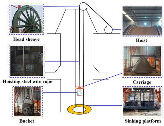
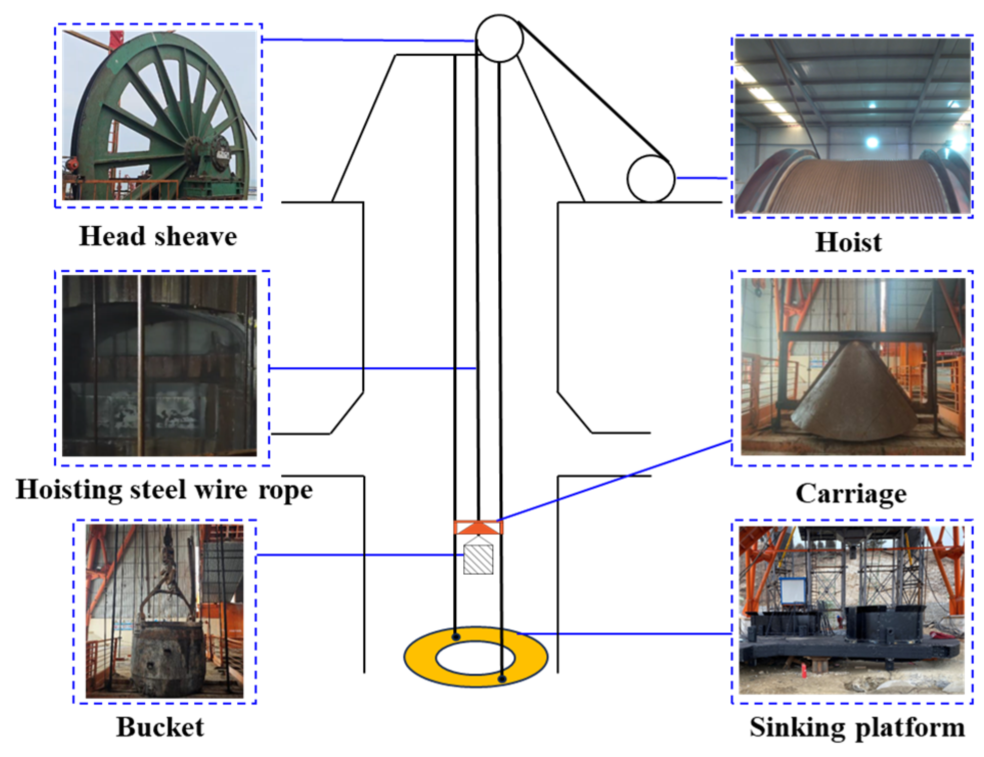
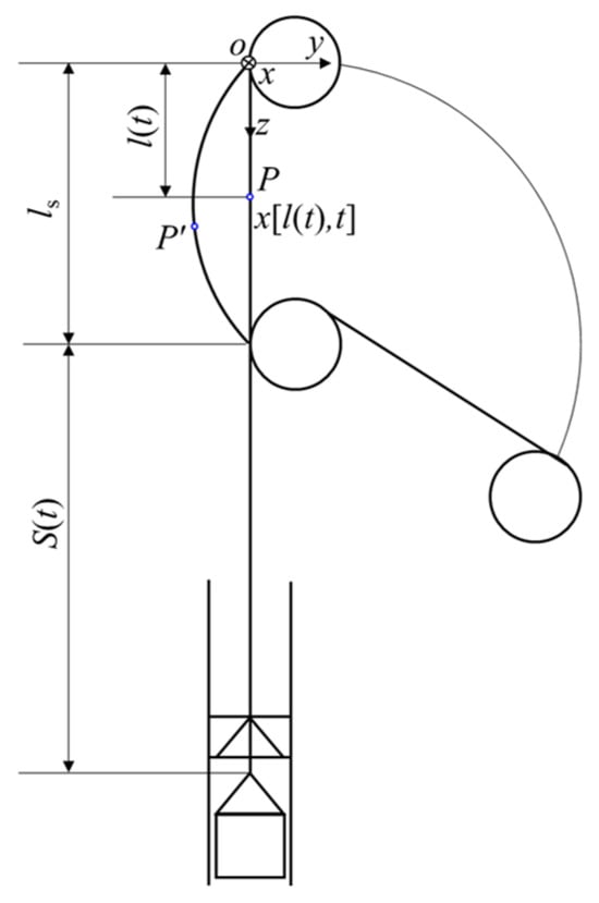
With the gradual depletion of shallow mineral resources worldwide, mineral exploitation is moving toward greater depths, and deep underground mining has become an important direction for mineral resource development [1,2,3]. In ultra-deep vertical shafts, the winding hoisting system is a key transportation system for material conveyance and personnel hoisting. As shown in Figure 1, it mainly consists of the drum, head sheave, hoisting vessel, and hoisting steel wire rope (hereafter referred to as the hoisting rope). The hoisting rope is the primary load-bearing and power-transmission component of the system. One end of the rope is wound on the drum in multiple layers, while the other end passes around the head sheave and connects to the hoisting vessel. The safe operation of the hoisting system directly affects the efficiency and reliability of underground mining operations [4,5,6].
Figure 1.
Hoisting system for ultra-deep vertical shaft.
Under ultra-deep hoisting conditions, the hoisting rope is subjected to time-varying rope length, longitudinal-torsional coupling, transverse vibration, and external excitation. These factors may induce abnormal winding behaviors, such as rope interlocking, rope jumping, and rope disorder. Such behaviors accelerate rope wear and wire breakage, reduce the load-bearing capacity and service life of the rope, and may lead to serious safety accidents [7,8,9]. Therefore, investigating abnormal winding behaviors of multi-layer wound hoisting ropes is important for drum design, rope service reliability, and operational safety in ultra-deep vertical shafts. Extensive studies have been conducted on the mechanisms, influencing factors, and prevention methods of abnormal winding behaviors in multi-layer wound hoisting ropes. Dietz et al. [10] investigated the contact force and deformation evolution between the drum and the hoisting rope under multi-layer winding conditions. Waters et al. [11] examined the tension attenuation caused by mutual extrusion between upper and lower rope layers. Peng et al. [12,13] established a dynamic rope-jumping model considering transverse vibration and showed that the inter-layer transition area is prone to rope-jumping. Huang et al. [14] developed a tension simulation model for rope jumping in multi-layer winding drums, and Yao et al. [15] reported that impact loads during inter-turn and inter-layer transitions increase the fleet angle and raise the probability of rope jumping and rope interlocking. In terms of prevention and control, Φидpoвcкaя et al. [16] proposed adding stepped transition blocks on both sides of the broken-line grooved drum, while Wieschel [17] and Johansson [18] suggested different central angles for transition areas to reduce abnormal winding.
Most existing studies remain at the stage of phenomenological description or qualitative analysis, and quantitative discrimination criteria for rope jumping and rope interlocking are still insufficient. To address this limitation, this study investigates rope jumping and rope interlocking during multi-layer winding on a double broken-line drum under ultra-deep vertical shaft hoisting conditions. Based on the existing static rope-jumping formulation, a dynamic rope-jumping discrimination approach considering transverse-vibration-induced fleet-angle variation is developed, and the evolution of rope-jumping risk during multi-layer winding is analyzed. The rope-jumping model is evaluated through industrial field tests. In addition, the effects of fleet angle, rope groove clearance, and drum-to-rope diameter ratio on rope interlocking are further analyzed. The results provide theoretical support for drum-parameter optimization and the prevention of abnormal winding behaviors in ultra-deep vertical shaft hoisting systems.
2. Discrimination Criteria for Rope Jumping and Rope Interlocking of the Multi-Layer Wound Hoisting Rope
2.1. Characteristics and Critical Conditions for Rope Jumping
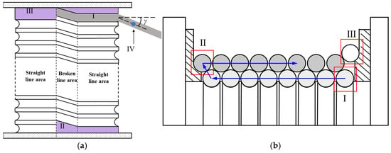
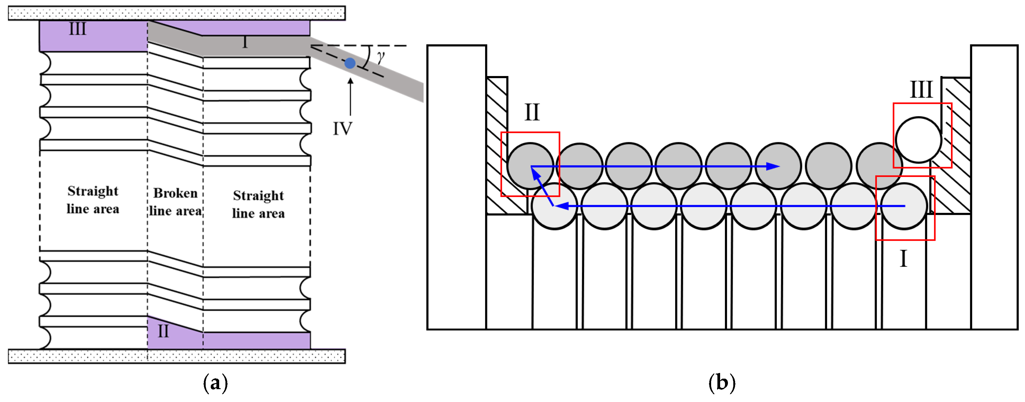
As shown in Figure 2, the contact object, stress state, and winding trajectory of the hoisting rope differ between the straight-line area and the broken-line area on the double broken-line drum [19,20]. Therefore, several typical winding positions are selected to analyze rope-jumping behavior. The rope starts from the initial winding point IV and passes successively through three representative positions (Figure 2a): the end position of the first-layer winding region (Position I), the starting position of the second layer after the 1st–2nd layer transition (Position II), and the end position of the third layer after the 2nd–3rd layer transition (Position III). Each representative position contains two observation areas, namely the straight-line area and the broken-line area, resulting in six analysis positions. The rope at Position I is in direct contact with the rope groove of the drum, whereas the ropes at Positions II and III are nested in the grooves formed by adjacent lower-layer ropes (Figure 2b). These different contact boundaries and radial support conditions provide the geometric basis for deriving the critical rope-jumping conditions at different winding layers.
Figure 2.
Representative inter-layer transition positions of the multi-layer wound hoisting rope: (a) plan view; (b) cross-sectional view. Blue arrows indicate the rope-winding direction, and red boxes indicate the representative inter-layer transition positions.
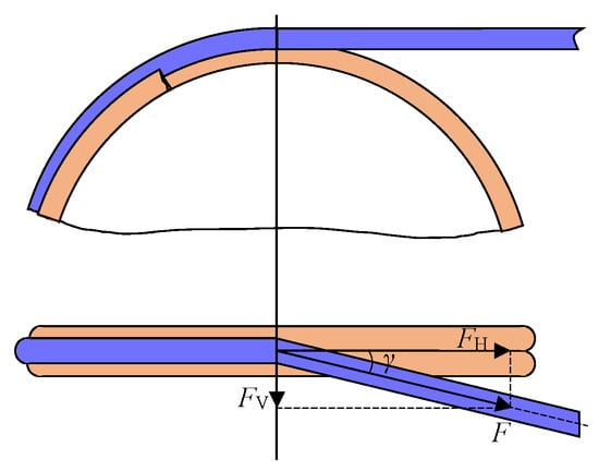
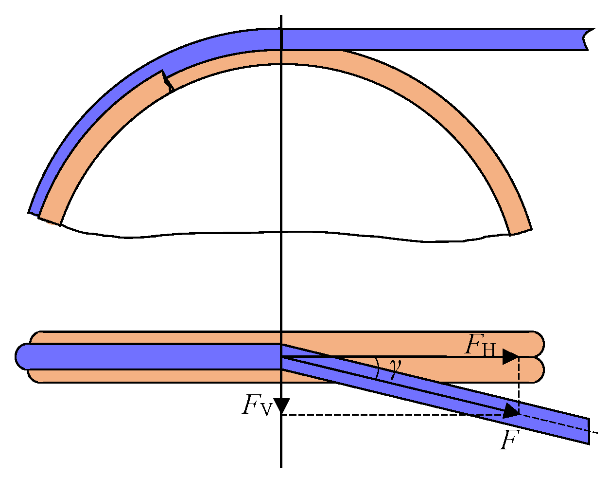
The fundamental mechanism of rope jumping during multi-layer winding is that the transverse force component of the hoisting rope exceeds the restraining force provided by the rope groove (Figure 3). The fleet angle γ of the hoisting rope, defined as the angle between the rope-exit axis and the vertical plane of the drum, determines the magnitude of the transverse force component. The rope tension F can be decomposed into a radial component FV perpendicular to the rope groove and a tangential component FH along the drum surface, as expressed in Equation (1).
Figure 3.
Force decomposition of the hoisting rope with a fleet angle.
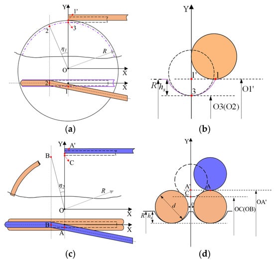
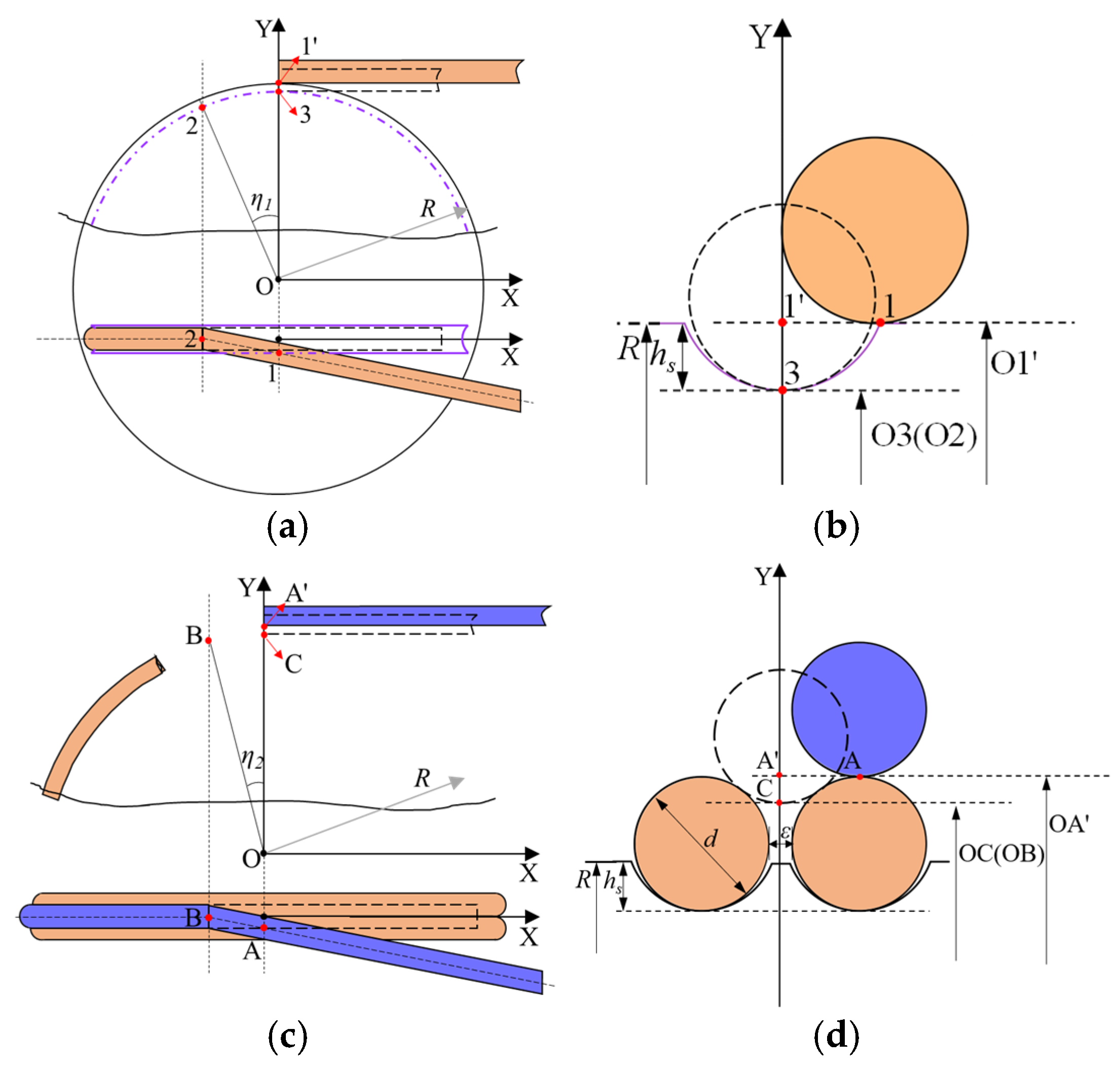
Based on the layered tangent geometric analysis framework of double broken-line drum multi-layer winding proposed by Gong et al. [21], this paper analyzes the rope-jumping geometric features for the first layer and upper winding layers (Figure 4). For the first layer (Figure 4a,b), the wire rope separates from its original groove and becomes tangent to the groove platform at Point 1 when rope jumping occurs. Arc 2–3 from the rope-jumping start Point 2 to the lowest normal winding Point 3 is defined as the rope-jumping segment with a corresponding central angle η1. For the second and third layers (Figure 4c,d), wire ropes are embedded in the gaps formed by lower adjacent ropes. In the event of rope jumping, the upper-layer rope becomes tangent to the outer surface of the underlying rope at Point A, and arc BC is the corresponding rope-jumping segment with central angle η2.
Figure 4.
Geometric model of rope jumping for multi-layer hoisting rope on double broken-line drum: (a) Winding trajectory of the first-layer rope; (b) OY-direction cross-section of the first layer; (c) Winding trajectory of second and third-layer ropes; (d) OY-direction cross-section of upper layers.
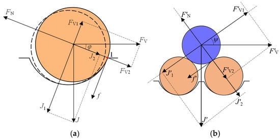
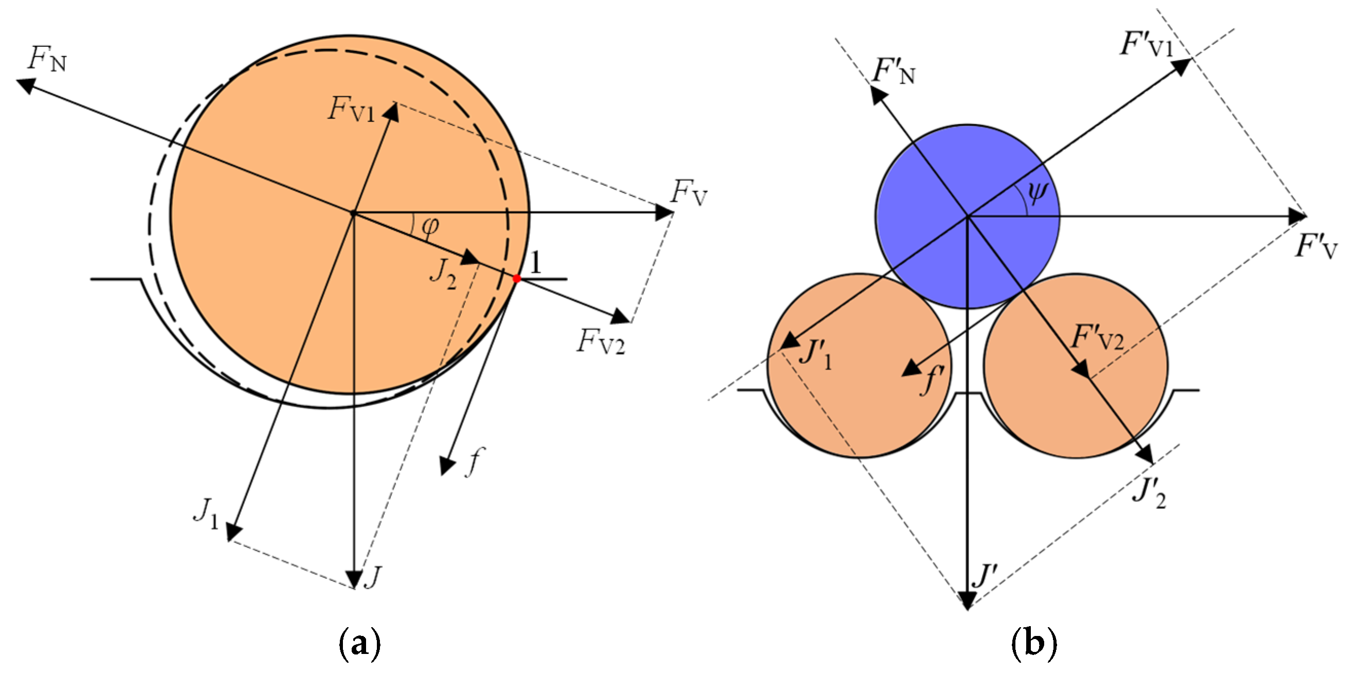
Figure 5 further illustrates the critical contact and force equilibrium conditions governing the onset of rope jumping under the action of the fleet angle. For the first winding layer (Figure 5a), the wire rope forms tangency with the groove gap platform at Point 1. To avoid rope jumping, the combined effect of contact friction f and the vertical component J of centripetal compression at the rope groove interface must counteract or exceed the vertical component FV1 of the lateral separation force; failure to satisfy this equilibrium condition will cause the rope to slip out of its groove and trigger rope jumping. For the second and third winding layers (Figure 5b), the upper wire rope tangentially contacts the outer surface of the underlying adjacent rope at Point A. Similarly, the sum of inter-rope friction f′ and the vertical component J′ of centripetal compression must balance or surpass the vertical component F′V1 of lateral force to prevent rope jumping.
Figure 5.
Critical contact and force conditions for rope jumping in multi-layer wound hoisting ropes: (a) first-layer hoisting rope; (b) second- and third-layer hoisting ropes.
Based on the static mechanical model of rope jumping during multi-layer winding and the static equilibrium relationships derived from the above geometric features, the formulas for the central angle of the rope-jumping segment and the helix angle in the broken-line zone, together with the static rope-jumping discrimination criteria in Equations (2) and (3), are obtained [22]. Specifically, Equation (2) is a unified geometric formula for calculating the central angle of rope-jumping segments applicable to all winding layers. Equation (3) serves as a dimensionless discriminant to assess rope-jumping risks in the straight-line zone of the drum.
where R is the radius of the drum; r0 denotes the bottom radius of the drum rope groove; hs is the depth of the rope groove; d is the diameter of the hoisting rope; D is the diameter of the drum; ε is the rope groove clearance; n is the number of winding layers; δ is a dimensionless discriminant. A larger value of δ indicates a lower likelihood of rope jumping in the straight-line area. μ is the friction coefficient at the rope contact interface, corresponding to rope–groove contact in the first winding layer and rope–rope contact in the upper winding layers.
The friction coefficient used in the rope-jumping model was experimentally determined under grease-lubricated conditions. The tests were conducted using the steel-wire-rope friction test rig reported in our previous studies [23,24], whereas the friction-coefficient values used in the present study were obtained from the current tests. Two contact configurations corresponding to the theoretical model were considered: rope–groove contact for the first winding layer and rope–rope contact for the upper winding layers. During each test, the tensions at the loading end and the fixed end were continuously measured. Based on the capstan relationship and the wrap angle of the test configuration, the friction coefficient was calculated as
where F1 and F2 are the measured tensions at the loading end and the fixed end, respectively. After an initial running-in stage, the friction coefficient fluctuated around a relatively stable level, and the mean value in the stable stage was taken as the representative friction coefficient. The measured mean friction coefficients were approximately 0.26 for rope–groove contact and 0.25 for rope–rope contact, as summarized in Table 1. Considering that the difference between the two measured values is only 0.01, a unified value of μ = 0.25 was adopted in the following calculations to maintain consistency in the model. Moreover, since a lower friction coefficient corresponds to a smaller stability margin in the straight-line rope-jumping criterion, the use of μ = 0.25 provides a slightly conservative evaluation.
Table 1.
Experimental determination of friction coefficients.
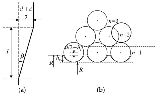
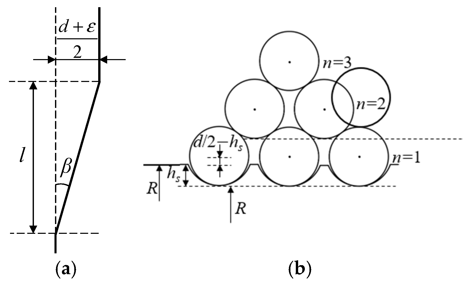
As shown in Figure 6, when the hoisting rope passes through the rope groove in the broken-line area during winding, it moves by half a rope groove pitch, (d + ε)/2, in the axial direction of the drum. Combined with the central angle of the broken-line area and the central radius of the rope loop, the helix angle β in the broken-line area is calculated by Equation (5) [22]. The rope-jumping behavior of the hoisting rope in the broken-line area is mainly governed by the relationship between the helix angle and the fleet angle. The dimensionless discriminant ξ for rope-jumping instability in the broken-line area is defined by Equation (6). Based on the critical rope-jumping criteria for the straight-line and broken-line areas, the ideal static condition for preventing rope jumping of a multi-layer wound hoisting rope on double broken-line drums under vibration-free operation is δ > 0 and ξ > 0.
where α is the central angle of the broken-line area; l is the corresponding arc length of the broken-line area on the winding drum; R is the radius of the winding drum.
Figure 6.
Geometric parameters for calculating the helix angle in the broken-line area: (a) helix angle in the broken-line area; (b) central radius of the nth layer rope loop.
In practical hoisting operations, the rope is subjected to dynamic loads while its length varies with time, which induce coupled torsional, transverse, and longitudinal vibrations. These vibrations cause transverse offset of the rope, which converts the static fleet angle γ into a time-varying dynamic fleet angle γ(t), and updates the parameters δ and ξ in real time. Among these vibration components, transverse vibration directly changes the lateral position and instantaneous spatial configuration of the rope segment between the drum and the head sheave, and therefore directly affects the fleet angle. In contrast, longitudinal and torsional vibrations mainly influence the fleet angle indirectly through variations in rope tension, effective length, and coupled vibration response. Previous studies have also identified catenary transverse vibration as an important factor affecting orderly multi-layer winding and abnormal winding behavior [25]. Therefore, the present study focuses on the transverse vibration component, while the indirect coupling effects of longitudinal and torsional vibrations are not explicitly considered. As shown in Figure 7, the hoisting rope is modeled as a continuous elastic body, considering only its transverse vibration; the axial coordinate of an arbitrary point P along the rope is l(t), P′ denotes the dynamically deformed position of P, ls is the length of the span-rope segment, and S(t) is the suspended rope length. Based on continuum mechanics theory, the governing equation for transverse vibration is given by Equation (7) [25]. In the previous study, the transverse vibration response was experimentally measured and compared with numerical predictions.
Figure 7.
Mechanical schematic of the hoisting rope in the ultra-deep shaft system.
Here, Tc = [m + ρS(t)]g represents the quasi-static axial tension associated with the terminal load and suspended rope weight, while the effect of hoisting acceleration is accounted for separately through the acceleration-dependent term in Equation (7). For the investigated system, a = 0.3 m/s2, corresponding to a/g ≈ 3.1%, indicating that the inertial correction to the axial tension is relatively small compared with the gravitational component. Following the parameter setting adopted in previous research on the transverse vibration of ultra-deep multi-layer winding hoisting ropes [25], cx = 0.9 is used in the present calculation. ρ is the linear density of the hoisting rope; x[l(t),t] represents the transverse vibration displacement of the hoisting rope; l(t) is the axial coordinate of an arbitrary point on the rope; E is the elastic modulus of the hoisting rope; A is the cross-sectional area of the hoisting rope; a is the hoisting acceleration; v is the steady-stage hoisting velocity.
The transverse displacement generated at the drum-side winding point during the inter-loop crossover is introduced as the boundary excitation of Equation (7). During one revolution of the drum, the transverse displacement excitation is expressed as
where x0 = (d + ε)/2, is the rope diameter, ε is the groove clearance, ω is the angular frequency of the displacement variation, ta is the crossover duration, and is the displacement variation period. For the investigated hoisting system, d = 56 mm and ε = 10 mm, giving x0 = 33 mm.
The boundary conditions at the drum-side winding point and the head-sheave end are x(0,t) = x0(t) and x(ls,t) = 0, respectively. The calculation starts from a vibration-free state, with the initial transverse displacement and velocity set to zero, i.e., x(l,0) = 0 and ∂x(l,0)/∂t = 0. To deal with the nonhomogeneous boundary condition, the transverse displacement is decomposed as x(l,t) = x1(l,t) + x2(l,t), where x2(l,t) = [1 − l/ls]x0(t). The homogeneous component is expanded using the Galerkin method as x1(l,t) = φᵀ(l)q(t), with φn(l) = sin(nπl/ls). A five-term truncation is adopted in the Galerkin expansion, with the first five transverse vibration modes retained in the numerical calculation. Accordingly, Equation (7) is transformed into a finite-dimensional system of ordinary differential equations. Following the numerical solution procedure adopted in previous research [25], the resulting equations are solved in MATLAB (version R2022b) using the ode45 algorithm with a time step of 0.001 s, a relative tolerance of 10−3, and an absolute tolerance of 10−6. The transverse vibration response x[l(t),t] is subsequently reconstructed from the calculated generalized-coordinate response. Since the spatial discretization is performed using the Galerkin method rather than a conventional mesh-based method, no finite-element-type mesh discretization is involved, while the temporal numerical accuracy is controlled by the adopted time step together with the relative and absolute tolerances of the ode45 solver.
The above numerical solution provides the transverse vibration response x[l(t),t] of the hoisting rope. According to the geometric relationship between the head sheave and the winding drum, the vibration-free fleet angle γt(t)is first determined. The transverse vibration displacement is then incorporated into the instantaneous rope geometry to obtain the dynamic fleet angle γa(t), as expressed in Equation (9). Accordingly, the dynamic fleet angle reflects the instantaneous geometric configuration of the rope after considering the transverse vibration displacement. Combining Equations (3) and (9), the dynamic fleet angle is introduced into the rope-jumping discriminants, and the corresponding rope-jumping criteria under transverse vibration are obtained, as expressed in Equations (10) and (11). In the present formulation, the transverse vibration response is used to update the instantaneous fleet angle for identifying the onset of rope jumping, while the subsequent contact loss, impact, and rope–groove collision processes are not explicitly considered.
2.2. Characteristics and Discrimination Criterion of Rope Interlocking
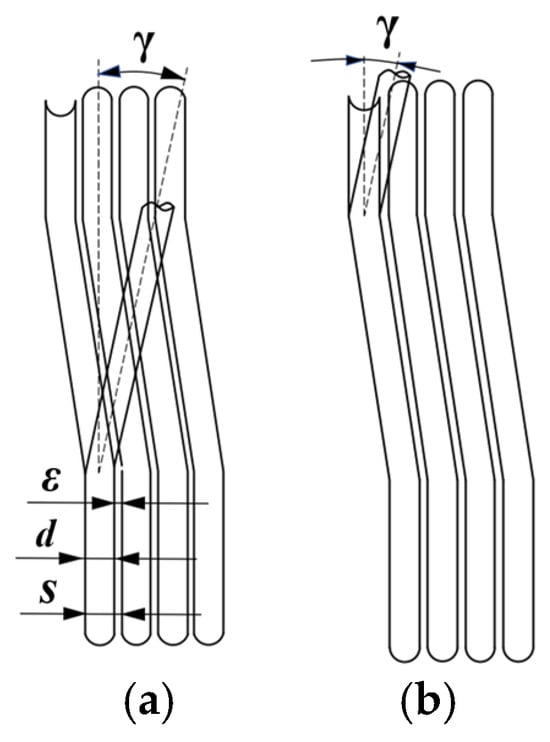
As shown in Figure 8, rope interlocking is an abnormal winding behavior. When the hoisting rope passes through the drum’s broken-line area (Figure 8a) or straight-line area (Figure 8b) during winding, it comes into contact with and compresses adjacent rope coils in the same layer. This interaction increases friction and abrasion wear.
Figure 8.
Interlocking behavior of multi-layer wound hoisting rope: (a) Broken-line area; (b) Straight-line area.
Following the geometric model reported in Ref. [26], the following assumptions are adopted for the rope-interlocking analysis:
- (1)
- The rope groove diameter is assumed to be equal to the hoisting rope diameter, and the elastic deformation of the hoisting rope during multi-layer winding is neglected.
- (2)
- The fleet angle varies only slightly within a single winding layer and is therefore assumed to be constant in the same layer.
- (3)
- The radial height increase caused by the rope groove depth and cumulative multi-layer stacking is neglected.
Therefore, the present analysis is conducted within the scope of these geometric assumptions, and non-ideal factors such as rope deformation and drum-groove deviations are not explicitly considered.
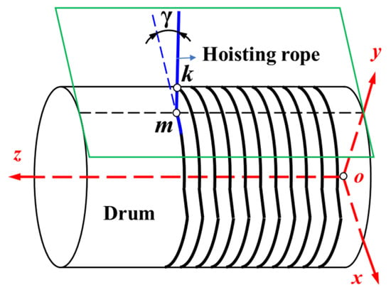
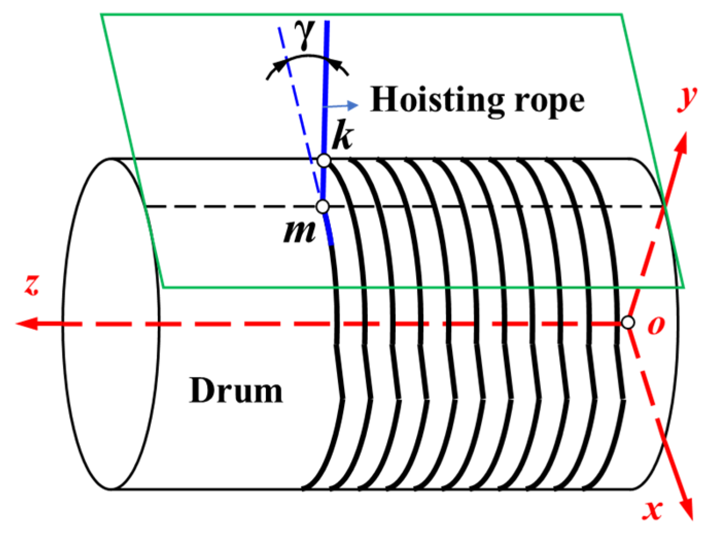
As shown in Figure 9, a spatial rectangular coordinate system is established. The origin O is located at the center of the right end face of the winding drum. The Z-axis coincides with the central axis of the drum and points to the left. The X-axis is located in the right end plane of the drum and is tangent to the drum cross-section at the rope-exit side. The Y-axis is perpendicular to the X–Z plane and points upward. Let m denote the rope-exit tangency point, k denote the rope-interlocking contact point, and γ denote the fleet angle of the outgoing rope segment. Based on the structural characteristics of the double broken-line drum and the spatial helical winding geometric theory [21], the spatial trajectory equations of the wound hoisting rope and the unwound chord segment are derived separately (Equations (12) and (13)).
where d is the hoisting rope diameter, R is the drum radius, l is the length of the broken-line area, s is the rope groove pitch, p is the distance between the rope-interlocking contact point τ and the rope-exit tangency point m, θ is the winding angle, and γ is the fleet angle of the outgoing rope segment.
Figure 9.
Spatial trajectory model of the multi-layer wound hoisting rope.
Based on the rope-biting geometric criterion reported in Ref. [26], the minimum spatial distance between the chord rope axis (the line connecting the rope-exit tangency point and the drum winding tangency point) and the central trajectory of the adjacent wound rope coil should exceed the nominal diameter of the hoisting rope to avoid rope interlocking. Using this criterion together with the spatial trajectory equations in Equations (12) and (13), the minimum inter-rope spacing in the straight-line area and the broken-line area is calculated using Equations (14) and (15), respectively.
Combining Equations (14) and (15), the quantitative criterion for rope interlocking is obtained:
The difference between the minimum spacing dPmin and the hoisting rope diameter d is defined as ζ. When ζ > 0, the spacing is sufficient and rope interlocking does not occur. When ζ ≤ 0, the spacing is insufficient and rope interlocking occurs.
3. Influence of Fleet Angle on Rope-Jumping Behavior
The hoisting system of an ultra-deep vertical shaft in a gold mine is used as the engineering case, and the operating parameters for the rope-jumping simulation are determined accordingly. In the simulation, the drum is wound with three layers, and 10 friction turns are reserved in the first layer. The hoisting cycle consists of three stages: acceleration, constant speed, and deceleration, with an effective hoisting height of 2005 m. The detailed parameters are listed in Table 2.
Table 2.
Parameters of the hoisting system for the ultra-deep shaft.
3.1. Influence of Transverse Vibration on Fleet Angle
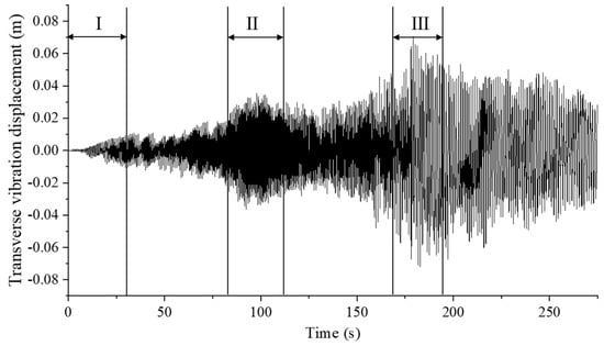
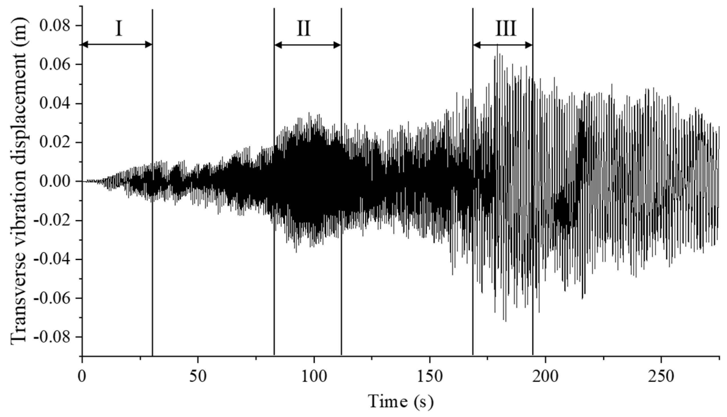
Using the parameters in Table 2 and the transverse vibration governing equation in Equation (7), the transverse vibration displacement response of the hoisting rope at the initial winding position IV is obtained (Figure 10). The transverse vibration amplitude remains below 0.02 m at the first-layer winding origin (Position I). As the winding layer number increases, the amplitude increases significantly at the 1st–2nd layer transition interface (Position II), but remains within 0.04 m. The maximum full-cycle vibration amplitude reaches 0.06 m at the 2nd–3rd layer transition interface (Position III). During the third-layer winding process, the amplitude gradually decreases as the excitation attenuates, but remains larger than in the first and second layers.
Figure 10.
Transverse vibration displacement of the hoisting rope.
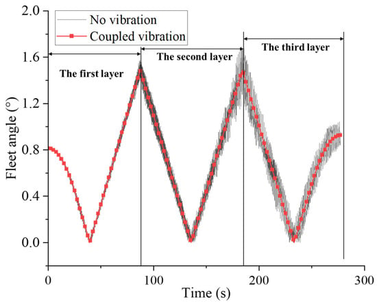
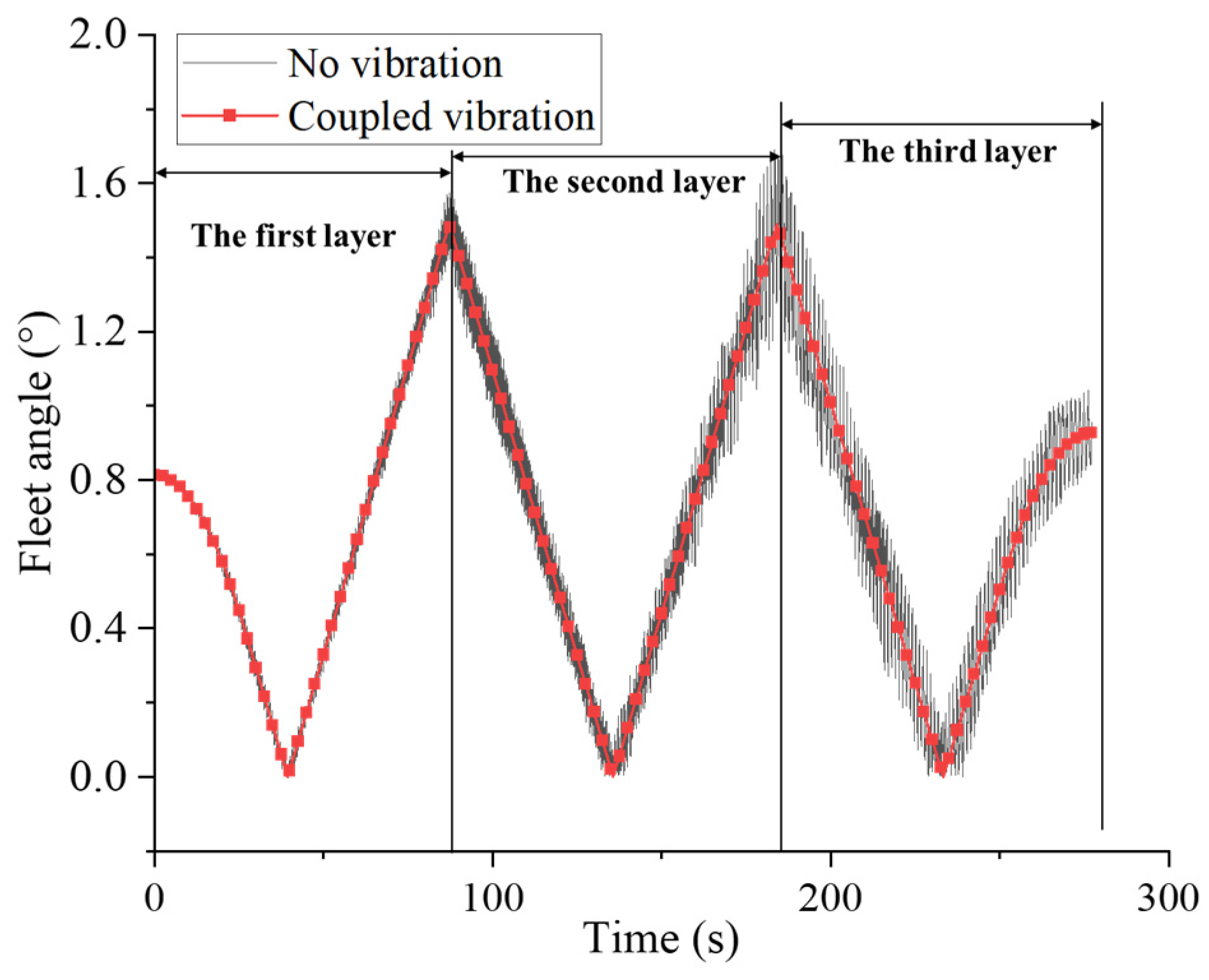
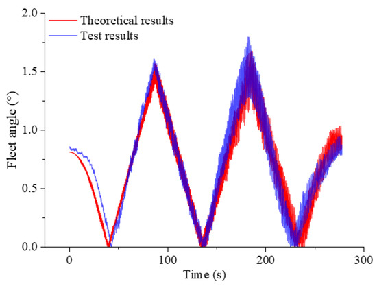
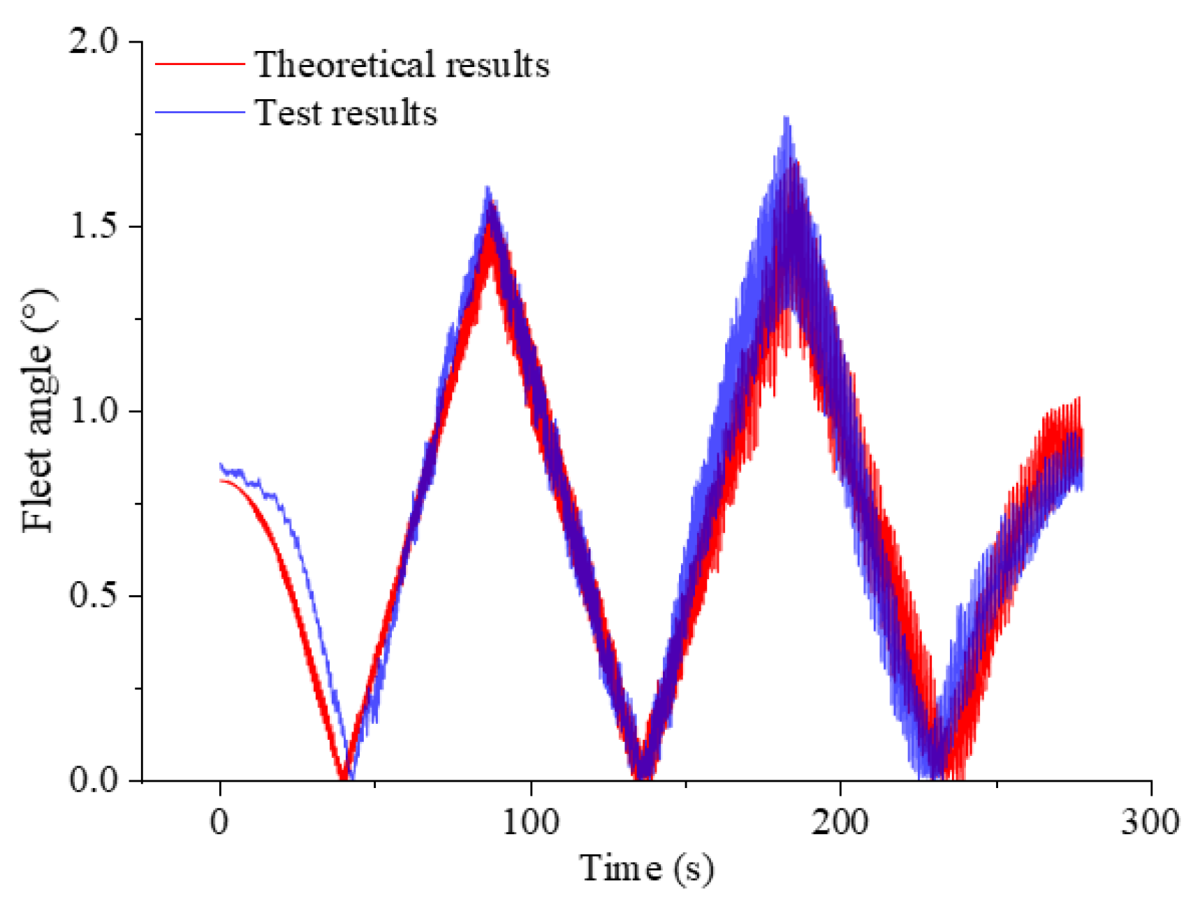
Based on the geometric relationship between the head sheave and the winding drum, together with the parameters in Table 2, the static fleet angle of the hoisting rope under vibration-free conditions is calculated. By incorporating the transverse vibration displacement into the instantaneous rope geometry, the time-varying dynamic fleet angle is obtained (Figure 11). The static fleet angle exhibits stable periodic variation under ideal vibration-free operation. At the initial winding position, the fleet angle is approximately 0.8° and gradually decreases to 0° at the axial midpoint of the drum. The static peak fleet angles at the 1st–2nd and 2nd–3rd layer transition interfaces are nearly identical, around 1.5°.
Figure 11.
Fleet angle of the hoisting rope under vibration-free and transverse-vibration conditions.
When transverse vibration displacement is considered, the fluctuation range of the rope-exit fleet angle increases with the winding layer number. The dynamic peak fleet angle at the 1st–2nd layer transition reaches 1.6°, 6.0% higher than the static peak. The maximum dynamic fleet angle at the 2nd–3rd layer transition rises to 1.7°, 13.4% higher than the static value, representing the extreme value over the full hoisting cycle. These results indicate that transverse vibration amplifies the rope-exit fleet angle, and the amplification becomes more pronounced with increasing winding layers. Consequently, the 2nd–3rd layer transition interface is identified as the critical high-risk region for rope-jumping instability.
3.2. Distribution of Rope-Jumping Discriminants at Typical Positions
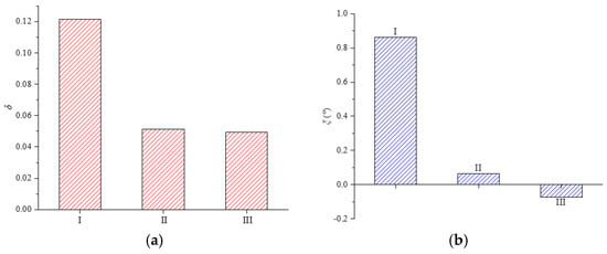
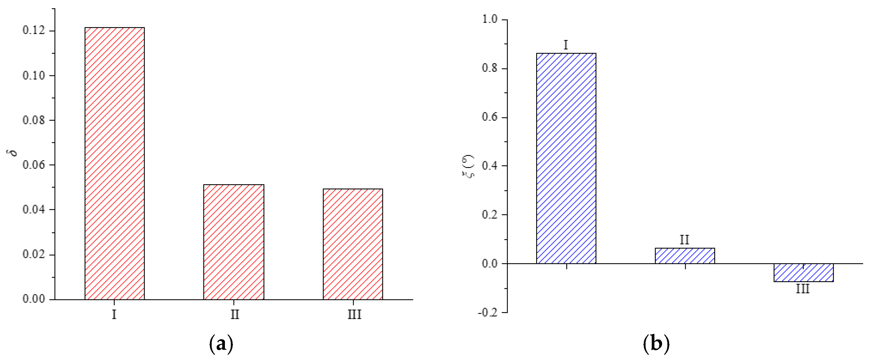
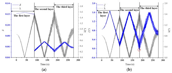
Using the dynamic fleet angles obtained in Section 3.1, the rope-jumping discriminants δ and ξ are calculated at three typical winding positions (Position I, Position II, and Position III). Figure 12 illustrates the distribution of these discriminants for the straight-line and broken-line areas. δ remains positive at Positions I and II in the straight-line area, indicating a stable winding state. At Position III, δ approaches zero, suggesting that the rope is close to the rope-jumping instability threshold (Figure 12a). Figure 12b shows that ξ in the broken-line area decreases more rapidly than δ in the straight-line area. Position III in the broken-line area exhibits the minimum ξ value, reaching the instability boundary first. This indicates that the broken-line segment is more prone to rope-jumping instability than the straight-line segment. Overall, Position III in the broken-line area is identified as the primary high-risk location for rope-jumping instability. These results provide quantitative support for monitoring and controlling rope-jumping behavior in multi-layer wound hoisting ropes.
Figure 12.
Distribution of rope-jumping discriminants at typical winding positions: (a) δ in the straight-line area; (b) ξ in the broken-line area.
3.3. Dynamic Evolution of Rope-Jumping Discriminants During Hoisting
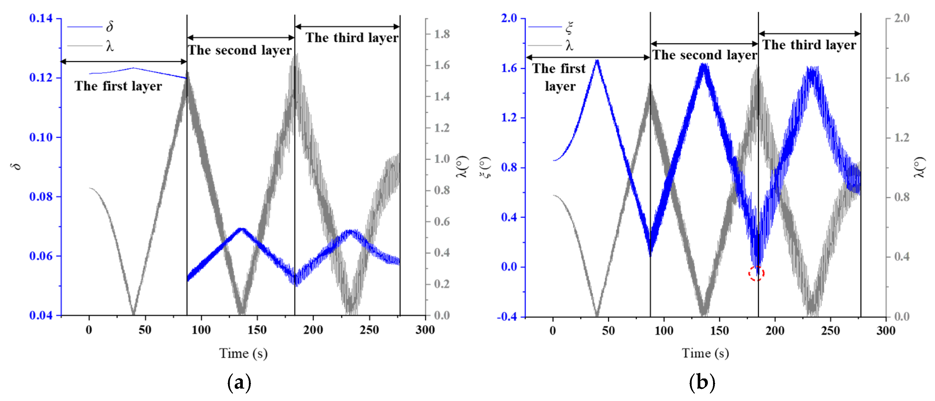
Figure 13 illustrates the time-varying evolution curves of δ(t) in the straight-line area and ξ(t) in the broken-line area during the hoisting process. As shown in Figure 13a, δ(t) is negatively correlated with the dynamic fleet angle and shows periodic variations with the rope winding position and operating stage. In the first winding layer, δ(t) reaches its maximum value at the axial midpoint of the drum, where the fleet angle is 0°, corresponding to the lowest rope-jumping risk in the straight-line area. As the winding layer number increases, transverse vibration excited by inter-layer and inter-coil transitions increases the dynamic fleet angle, resulting in a stepwise decrease in the overall δ(t) value. Local minima of δ(t) occur at the 1st–2nd and 2nd–3rd layer transition interfaces, and the minimum value appears at the 2nd–3rd layer transition, indicating the highest rope-jumping risk among the straight-line positions. As shown in Figure 13b, ξ(t) in the broken-line area remains above the critical boundary of 0 during the first and second winding layers, indicating that rope jumping does not occur in these stages. During the third winding layer, however, ξ(t) falls below the critical threshold at the 2nd–3rd layer transition due to the increase in dynamic fleet angle caused by transverse vibration, indicating a high probability of rope jumping. Compared with δ(t) in the straight-line area, ξ(t) in the broken-line area is more sensitive to fleet angle variation. Therefore, the 2nd–3rd layer transition in the broken-line area is identified as the most vulnerable region for rope jumping.
Figure 13.
Dynamic evolution of rope-jumping discriminants during hoisting: (a) δ(t) in the straight-line area; (b) ξ(t) in the broken-line area. The red dashed circle highlights the critical point at the 2nd–3rd layer transition where ξ(t) approaches the rope-jumping instability threshold.
3.4. Critical Fleet Angle for Rope Jumping
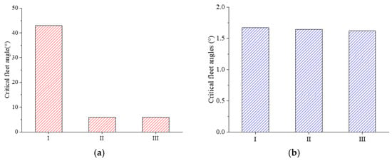
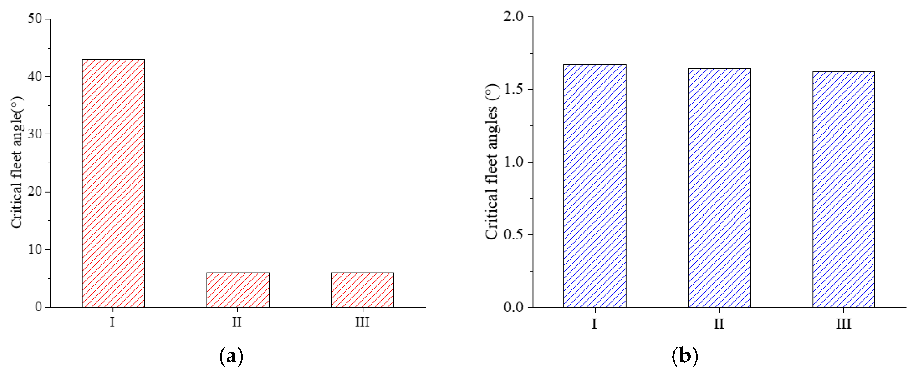
To determine the critical fleet angle for the onset of rope jumping, the critical boundaries δ = 0 and ξ = 0 are used for the straight-line and broken-line areas, respectively. Using the parameters in Table 2, the critical fleet angles at typical winding positions are calculated (Figure 14). The critical fleet angles at Position I, Position II, and Position III in the straight-line area are 43.0°, 6.1°, and 6.0°, respectively. These values are much higher than the maximum allowable fleet angle of 1.5° (1°30′) specified for winding hoisting systems in the relevant Chinese national standards [27,28], indicating that rope jumping is unlikely to occur in the straight-line area under the specified operating conditions (Figure 14a).
Figure 14.
Critical fleet angles for rope jumping at typical winding positions: (a) straight-line area; (b) broken-line area.
In comparison, the critical fleet angles at Position I, Position II, and Position III in the broken-line area are 1.67°, 1.64°, and 1.62°, respectively, which are close to this allowable limit of 1.5° (Figure 14b).
This indicates that the broken-line area has a much lower stability margin than the straight-line area and is more susceptible to rope-jumping instability. Therefore, the broken-line area should be considered the key region for rope-jumping risk control during multi-layer winding.
3.5. Sensitivity Analysis of the Friction Coefficient
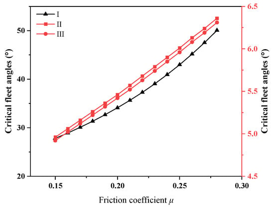
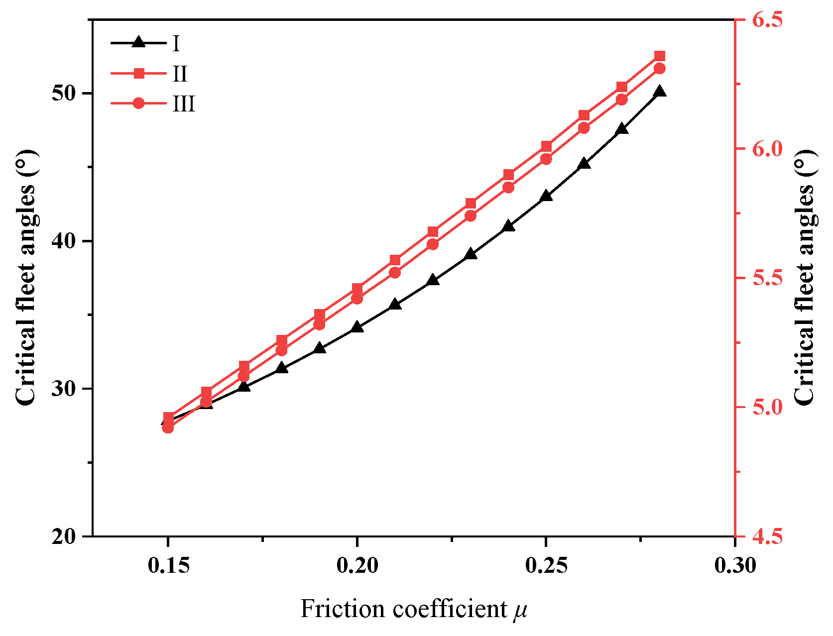
In the present formulation, the friction coefficient explicitly appears in the straight-line rope-jumping discriminant , whereas the broken-line discriminant is defined as the difference between the broken-line helix angle and the instantaneous fleet angle and does not explicitly contain . Therefore, the sensitivity analysis of the friction coefficient is performed only for the straight-line rope-jumping criterion. According to the reported range for lubricated steel wire ropes [29], was varied from 0.15 to 0.28. The corresponding critical fleet angles in the straight-line area were recalculated using the straight-line rope-jumping criterion.
As shown in Figure 15, the results show that the critical fleet angle increases monotonically with the friction coefficient. As increases from 0.15 to 0.28, the critical fleet angle at Position I increases from 27.82° to 50.06°, while those at Positions II and III increase from 4.96° to 6.36° and from 4.92° to 6.31°, respectively. Although the absolute critical fleet angles vary with , the relative risk ranking of the three representative positions remains unchanged throughout the investigated range, with Position III exhibiting the lowest critical fleet angle, followed by Position II, while Position I shows the highest value.
Figure 15.
Sensitivity of the critical fleet angles at Positions I-III in the straight-line area to the friction coefficient.
At the baseline value of , the critical fleet angles at Positions I, II, and III are 42.99°, 6.01°, and 5.96°, respectively, consistent with the results presented in Section 3.4. Compared with the calculated dynamic fleet angles, the straight-line critical fleet angles remain substantially larger throughout the investigated range. This indicates that, although the friction coefficient affects the magnitude of the critical fleet angle, the conclusion that rope jumping does not occur in the straight-line area remains robust within the investigated range of the friction coefficient.
3.6. Industrial Field Evaluation
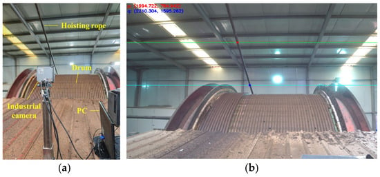
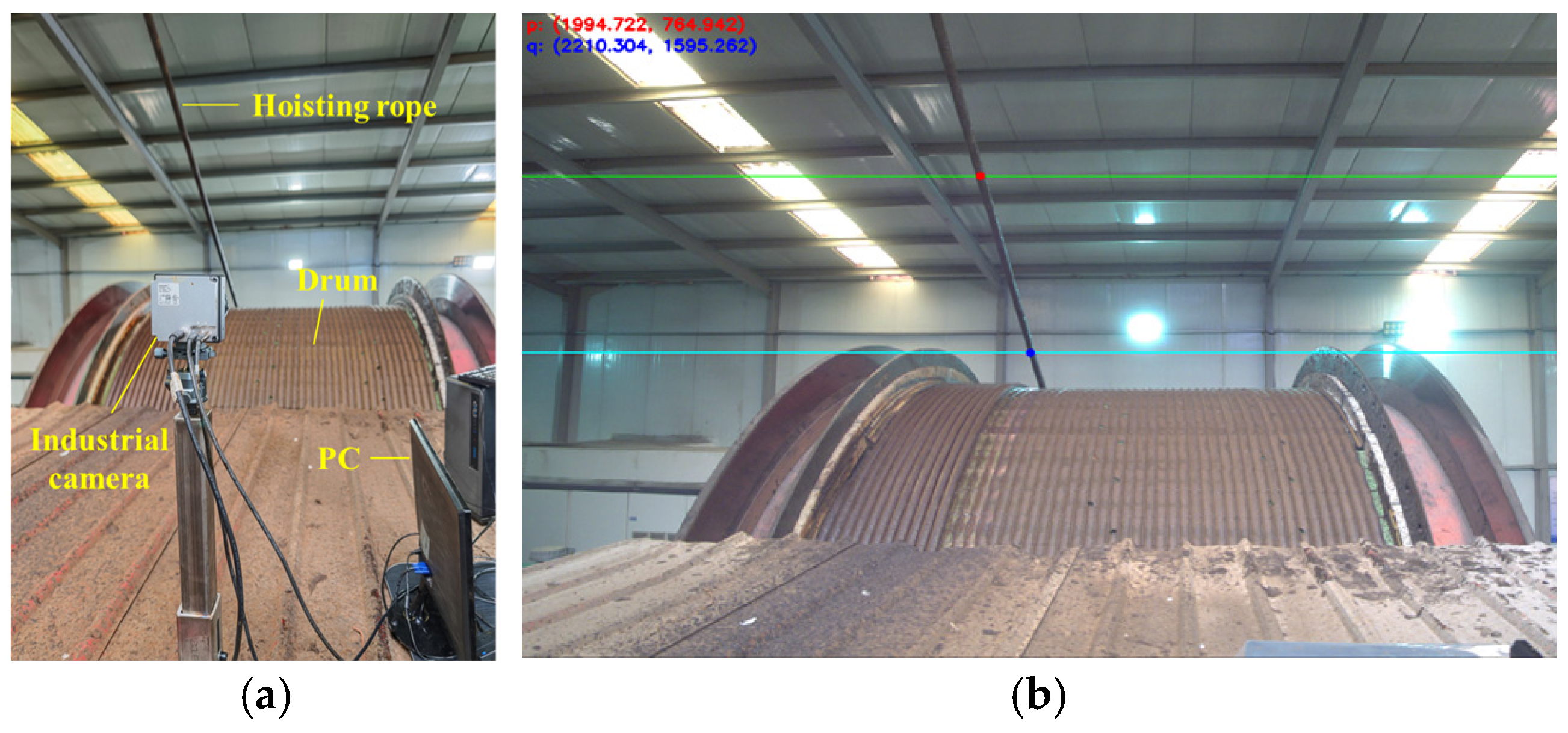
Field monitoring was conducted on the hoisting rope in an ultra-deep vertical shaft at a gold mine (Figure 16). The test parameters were consistent with those used in the numerical simulation. A Basler boA5320-150cc industrial camera (Basler AG, Ahrensburg, Germany) with a resolution of 5320 × 3032 pixels was used at a sampling frequency of 100 Hz, together with a C11-0824-12M-P lens (Basler AG, Ahrensburg, Germany) with a focal length of 8.46 mm. Image acquisition was performed using the Basler pylon Software Suite 8 (Basler AG, Ahrensburg, Germany). The camera was fixed in front of the winding drum, and its field of view covered the 3 m-wide drum and the outgoing rope segment throughout the winding process. A sequence of winding images was acquired and transmitted to the PC for rope-state monitoring, as shown in Figure 16a. Meanwhile, a feature-point optical-flow tracking algorithm was used to identify the outgoing rope segment and obtain the image coordinates of the tracked feature points with subpixel refinement [30,31], as illustrated in Figure 16b.
Figure 16.
Machine vision monitoring system for hoisting rope operating states: (a) monitoring equipment; (b) fleet angle identification of hoisting rope. In (b), the red and blue points denote the two tracked feature points, while the green and blue lines are auxiliary reference lines used for position identification.
An in situ direct calibration procedure was adopted to establish the mapping between the image plane and the physical rope-exit plane. During winding, the outgoing rope remains tangent to the head sheave at an approximately fixed point; therefore, the rope-exit lines at different winding positions form a family of concurrent lines. The rope-exit lines at the beginning and end of the first winding layer were selected as two reference lines. Their homogeneous line coordinates in the physical rope-exit plane are denoted by lw1 = (aw1,bw1,cw1)T and lw2 = (aw2,bw2,cw2)T, while the corresponding image-plane lines are denoted by lp1 = (ap1,bp1,cp1)T and lp2 = (ap2,bp2,cp2)T. Here, a, b, and are the coefficients of the line equation in the physical rope-exit plane or in the image plane, where and denote the physical and pixel coordinates, respectively. Based on these two line correspondences, the transformation matrix H is obtained as
where is the transformation matrix from the image-plane rope-exit line to the corresponding line in the physical rope-exit plane. For each subsequent image frame, two tracked feature points are used to determine the instantaneous rope-exit line in the image plane. The corresponding rope-exit line in the physical plane is calculated as
where denotes the homogeneous coordinates of the instantaneous rope-exit line in the physical rope-exit plane. The instantaneous fleet angle is then calculated by
where is the instantaneous fleet angle, and and are the first two coefficients of the physical rope-exit line . The tracked image coordinates were refined to subpixel accuracy to reduce pixel-quantization error. A separate quantitative uncertainty budget for the optical-flow tracking was not established during the field campaign; therefore, an independent numerical tracking uncertainty is not reported in the present study.
The 100 Hz acquisition frequency corresponds to a temporal resolution of 0.01 s. For the investigated system, the drum radius is 2.75 m, the broken-line central angle is 0.41 rad, and the maximum hoisting speed is 8 m/s. Accordingly, the characteristic crossover duration is approximately s, corresponding to approximately 14 image frames. The adopted sampling frequency is therefore sufficient to resolve the fleet-angle variation associated with the crossover process considered in this study. High-frequency impact and post-contact collision processes are not the measurement targets of the present field monitoring.
The dynamic fleet angle was continuously recorded throughout the complete hoisting process. As shown in Figure 17, the calculated and measured fleet angles exhibit similar overall variation trends throughout the monitored winding process, including the characteristic changes associated with the inter-layer transitions. For quantitative comparison, representative fleet-angle values at Positions I–III were extracted from the complete measured time history; these values do not represent the only measured data points. The calculated and measured values at Positions I, II, and III are 0.81° and 0.86°, 1.58° and 1.61°, and 1.69° and 1.78°, respectively, corresponding to relative errors of 6.2%, 1.9%, and 5.3%, as summarized in Table 3. The relative errors at the three representative positions are all below 7.0%, indicating reasonable agreement between the calculated and measured dynamic fleet angles under the examined operating condition.
Figure 17.
Comparison between calculated and measured fleet angles.
Table 3.
Comparison of test and theoretical values of fleet angle at typical positions.
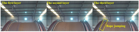
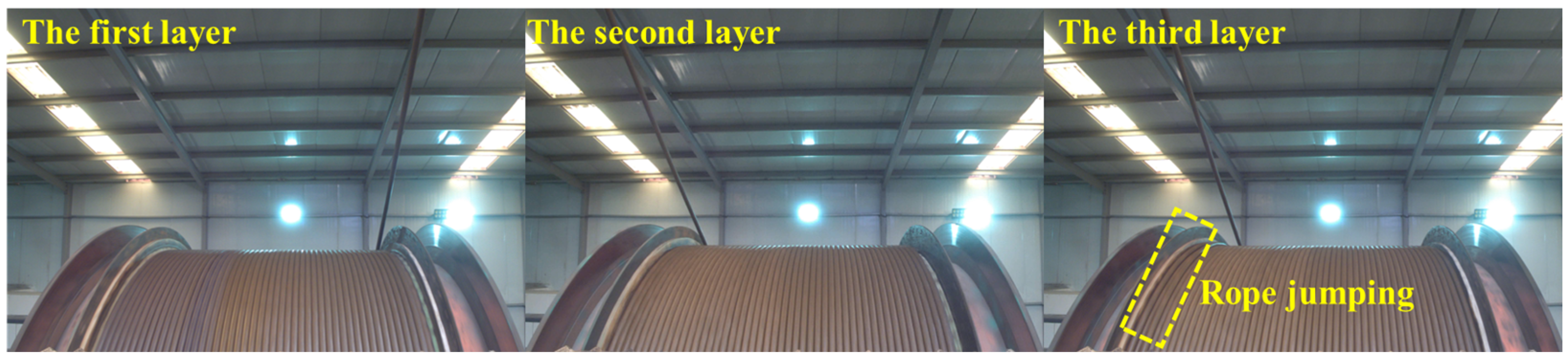
For a threshold-oriented comparison, the measured fleet angles were further compared with the corresponding critical fleet angles in the broken-line area. At Position I, the measured fleet angle is 0.86°, which is below the critical value of 1.67°, and no rope jumping was observed. At Position II, the measured value is 1.61°, slightly below the critical value of 1.64°, and no rope jumping was observed. In contrast, at Position III, the measured fleet angle reaches 1.78°, exceeding the critical value of 1.62°, and rope jumping was observed at the initial turns of the third layer after the 2nd–3rd layer transition (Figure 18). These observations show consistency between the measured fleet-angle levels and the occurrence or non-occurrence of rope jumping at the three representative positions. It should be noted that the 1.5° value specified in the relevant Chinese standards [27,28] is a regulatory/design limit rather than a rope-jumping instability threshold; therefore, exceeding 1.5° does not necessarily indicate the occurrence of rope jumping if the fleet angle remains below the predicted critical value.
Figure 18.
Field observation of rope jumping during third-layer winding.
Although the quantitative critical fleet angles obtained in this study are system-specific, the proposed analysis framework can be applied to other multi-layer winding hoisting systems by introducing the corresponding drum geometry, rope parameters, and operating conditions.
4. Influence of Key Parameters on Rope-Interlocking Behavior
Based on the rope-interlocking discrimination criterion, two calculation scenarios are established to investigate the influence of key structural parameters of the drum on hoisting rope interlocking behavior, as detailed below:
- Given the drum-to-rope diameter ratio e (defined as the ratio of drum diameter D to hoisting rope diameter d: e = D/d) and fleet angle γ, solve for the minimum rope groove clearance coefficient kε (kε = ε/d, where ε denotes the rope groove clearance) that prevents interlocking.
- Given the drum-to-rope diameter ratio e and rope groove clearance coefficient kε, solve for the maximum fleet angle γ that prevents interlocking.
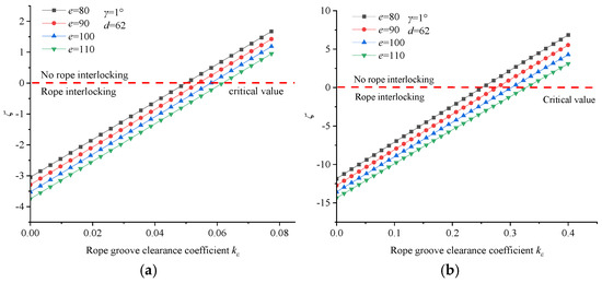
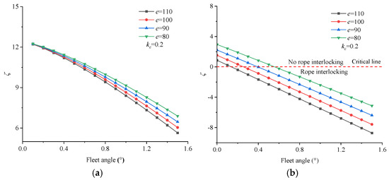
Section 4.1, Section 4.2 and Section 4.3 examine the general effects of key design parameters on rope-interlocking behavior over representative engineering ranges. According to the relevant Chinese standards [27,28], the drum-to-rope diameter ratio should be no less than 80 and the fleet angle should not exceed . Therefore, –110 is considered and the fleet angle is varied up to to retain a design margin; different rope–groove clearance coefficients are selected to investigate the trade-off between avoiding rope interlocking and maintaining sufficient winding capacity, since an excessively small clearance increases the interlocking risk, whereas an excessively large clearance reduces the number of rope turns accommodated on the drum.
4.1. Influence of Drum-to-Rope Diameter Ratio on Rope-Interlocking Behavior
Four drum-to-rope diameter ratios are selected to analyze their influence on rope-interlocking behavior (Figure 19). When the fleet angle remains constant, the minimum rope groove clearance coefficient required to avoid rope interlocking increases with the drum-to-rope diameter ratio. This indicates that a larger drum-to-rope diameter ratio requires a larger rope groove clearance coefficient to maintain sufficient spacing between the outgoing rope segment and the adjacent wound rope coil. In addition, the required minimum rope groove clearance coefficient in the broken-line area is greater than that in the straight-line area, indicating that the broken-line area is more prone to rope interlocking. Therefore, when the fleet angle is fixed, the minimum rope groove clearance coefficient should be determined according to the calculation results of the broken-line area.
Figure 19.
Minimum rope groove clearance coefficients under different drum-to-rope diameter ratios: (a) straight-line area; (b) broken-line area.
The maximum allowable fleet angle under different drum-to-rope diameter ratios is calculated (Figure 20). Considering the maximum allowable fleet angle of 1.5° specified in the relevant Chinese national standards, the fleet-angle range of 0–1.5° is examined. Within this range, the values in the straight-line area remain greater than 0, indicating that rope interlocking does not occur in the straight-line area (Figure 20a). In the broken-line area, the maximum allowable fleet angle decreases as the drum-to-rope diameter ratio increases (Figure 20b). This means that, under a fixed rope groove clearance coefficient, a larger drum-to-rope diameter ratio narrows the allowable fleet-angle range for avoiding rope interlocking. Overall, the influence of the drum-to-rope diameter ratio on rope interlocking depends on the design constraint. When the fleet angle is fixed, a larger drum-to-rope diameter ratio requires a larger rope groove clearance coefficient. When the rope groove clearance coefficient is fixed, a larger drum-to-rope diameter ratio reduces the maximum allowable fleet angle. Therefore, the drum-to-rope diameter ratio should be considered together with the fleet angle and rope groove clearance coefficient, and the broken-line area should be taken as the controlling region for drum parameter design.
Figure 20.
Maximum fleet angle of hoisting rope under different drum-to-rope diameter ratios: (a) Straight-line area; (b) Broken-line area.
4.2. Influence of Fleet Angle on Rope-Interlocking Behavior
Four fleet angles are selected to analyze the effect of fleet angle on rope interlocking at a fixed drum-to-rope diameter ratio e. The minimum rope groove clearance coefficient required to prevent interlocking is calculated (Figure 21). With a fixed drum-to-rope diameter ratio, the minimum rope groove clearance coefficient required to prevent rope interlocking increases as the fleet angle increases. A comparison between the straight-line area (Figure 21a) and the broken-line area (Figure 21b) shows that the broken-line area requires a larger rope groove clearance coefficient to reach the non-interlocking boundary. This indicates that rope interlocking is more likely to occur in the broken-line area. Therefore, the minimum rope groove clearance coefficient should be designed according to the calculation results of the broken-line area.
Figure 21.
Minimum rope groove clearance coefficients under different fleet angles: (a) straight-line area; (b) broken-line area.
4.3. Influence of Rope Groove Clearance Coefficient on Rope-Interlocking Behavior
The rope groove clearance coefficient kε is defined as the ratio of rope groove clearance to hoisting rope diameter, and it directly affects the spacing between adjacent wound rope coils. Several representative values of parameter kε are selected to calculate the maximum allowable fleet angle under a fixed drum-to-rope diameter ratio e (Figure 22). Within the fleet angle range of 0–1.5°, all calculated ζ values in the straight-line area remain greater than 0, indicating that rope interlocking does not occur in this area. In the broken-line area, under a constant drum-to-rope diameter ratio, a smaller rope groove clearance coefficient corresponds to a smaller maximum allowable fleet angle. This indicates that reducing the rope groove clearance coefficient narrows the safe winding range and increases the risk of rope interlocking. Overall, the rope groove clearance coefficient is an important parameter affecting rope interlocking. Increasing kε can enlarge the spacing margin between adjacent rope coils and improve the drum’s resistance to rope interlocking. Therefore, the rope groove clearance coefficient should be reasonably selected together with the fleet angle and drum-to-rope diameter ratio, especially for the broken-line area.
Figure 22.
Maximum fleet angle of hoisting rope under different rope groove clearance coefficients: (a) straight-line area; (b) broken-line area.
5. Conclusions
This study investigates two abnormal winding behaviors of the hoisting rope, namely rope jumping and rope interlocking, during multi-layer winding on a double broken-line drum in ultra-deep vertical shafts. The effects of fleet angle, rope–groove clearance coefficient, and drum-to-rope diameter ratio are analyzed, and the proposed dynamic rope-jumping approach is evaluated using industrial field measurements. The main conclusions are as follows:
(1) The critical fleet angles in the broken-line area are 1.67°, 1.64°, and 1.62°, much lower than those in the straight-line area, namely 43.0°, 6.1°, and 6.0°. Rope jumping is most likely at the transition between the second and third layers in the broken-line area. Transverse vibration increases the dynamic fleet angle, with greater amplification at higher winding layers, thereby reducing the stability margin.
(2) Rope interlocking is more likely in the broken-line area than in the straight-line area. The risk increases with a larger fleet angle or a smaller rope groove clearance coefficient. The drum-to-rope diameter ratio affects the interlocking boundary by changing the required groove clearance and allowable fleet angle. For a fixed fleet angle, a larger diameter ratio requires a larger groove clearance coefficient; for a fixed groove clearance coefficient, it reduces the allowable fleet angle. These parameters should be considered together in drum design.
(3) At the three representative winding positions, the calculated dynamic fleet angles show reasonable agreement with the field measurements, with relative errors of 6.2%, 1.9%, and 5.3%, respectively. During the monitored hoisting process, rope jumping was observed at the predicted high-risk location, providing field-based support for the model in identifying rope-jumping susceptibility under the examined operating condition.
The present framework evaluates abnormal winding behavior under the specified rope condition and operating state, with the rope and groove geometry and mechanical parameters treated as fixed values. Service-life-dependent changes in rope surface condition, lubrication state, wear, effective rope diameter, radial stiffness/contact compliance, damping characteristics, and groove geometry are not explicitly incorporated into the current model. These factors may alter the contact conditions, vibration response, and the resulting critical fleet angle or inter-rope spacing during long-term service. Therefore, the quantitative results obtained in this study should be interpreted within the examined operating condition, while further extension of the framework should incorporate condition-dependent parameter evolution for long-term service-life assessment.
Author Contributions
Methodology, W.F. and S.G.; investigation, Y.S. and X.D.; data curation, D.W., Y.S. and X.D.; writing—original draft preparation, D.W.; writing—review and editing, D.W. and S.G.; visualization, D.W., Y.S. and X.D.; supervision, W.F. and S.G.; project administration, W.F.; funding acquisition, W.F. All authors have read and agreed to the published version of the manuscript.
Funding
This research was supported by the Major Science and Technology Special Project of China National Coal Group Corporation (Grant No. 20231BY001).
Data Availability Statement
The datasets generated and/or analyzed during the current study are not publicly available due to confidentiality restrictions related to industrial field data, but may be available from the corresponding author upon reasonable request and with permission from the relevant organization.
Acknowledgments
The authors would like to thank all individuals who provided assistance and support during this study.
Conflicts of Interest
The authors declare that they have no known competing financial interests or personal relationships that could have appeared to influence the work reported in this paper.
References
- Ranjith, P.G.; Zhao, J.; Ju, M.H.; Silva, R.V.S.D.; Rathnaweera, T.D.; Bandara, A.K.M.S. Opportunities and challenges in deep mining: A brief review. Engineering 2017, 3, 546–551. [Google Scholar] [CrossRef] [Scilit]
- Ghorbani, Y.; Nwaila, G.T.; Zhang, S.E.; Bourdeau, J.E.; Cánovas, M.; Arzua, J.; Nikadat, N. Moving towards deep underground mineral resources: Drivers, challenges and potential solutions. Resour. Policy 2023, 80, 103222. [Google Scholar] [CrossRef] [Scilit]
- Shi, L.X.; Tan, J.P.; Xue, S.H.; Deng, J.W. Inspection method of rope arrangement in the ultra-deep mine hoist based on optical projection and machine vision. Sensors 2021, 21, 1769. [Google Scholar] [CrossRef] [Scilit]
- Zhu, Y.; Xu, T.; Ma, C.; Yao, J.N. Experimental study on longitudinal vibration of mine hoisting rope subjected to disturbance excitations by ADAMS. Adv. Mech. Eng. 2022, 14, 16878132221076818. [Google Scholar] [CrossRef] [Scilit]
- Xie, H.; Tang, Y.; Shen, G.; Li, X. Neural adaptive braking control for single rope winding hoisting systems with disturbance compensation. Proc. Inst. Mech. Eng. Part I J. Syst. Control Eng. 2023, 237, 3148–3162. [Google Scholar] [CrossRef] [Scilit]
- Wang, Y.D.; Zhu, W.D.; Kou, Z.M. Dynamic simulation of a dual-cable parallel winding hoisting system with flexible guides. Int. J. Struct. Stab. Dyn. 2022, 22, 2250018. [Google Scholar] [CrossRef] [Scilit]
- Verreet, R. Steel wire rope damage due to bending fatigue and drum crushing. OIPEEC Bull. 2003, 85, 27–46. [Google Scholar]
- Wang, D.G.; Zhang, D.K.; Ge, S.R. Effect of displacement amplitude on fretting fatigue behavior of hoisting rope wires in low cycle fatigue. Tribol. Int. 2012, 52, 178–189. [Google Scholar] [CrossRef] [Scilit]
- Zhang, J.; Wang, D.G.; Zhang, D.K.; Ge, S.R.; Wang, D.A. Dynamic torsional characteristics of mine hoisting rope and its internal spiral components. Tribol. Int. 2017, 109, 182–191. [Google Scholar] [CrossRef] [Scilit]
- Dietz, P. Design criteria for multilayer wound winch drums following lightweight design principles. In Proceedings of the 8th International Design Conference, Dubrovnik, Croatia, 17–20 May 2004; pp. 15–20. [Google Scholar]
- Waters, E.O. Rational design of hoisting drums. Trans. ASME 1920, 42, 463–485. [Google Scholar] [CrossRef] [Scilit]
- Peng, X.; Gong, X.S.; Liu, J.J. The study on crossover layouts of multi-layer winding grooves in deep mine hoists based on transverse vibration characteristics of catenary rope. Proc. Inst. Mech. Eng. Part I J. Syst. Control Eng. 2019, 233, 118–132. [Google Scholar] [CrossRef] [Scilit]
- Peng, X.; Gong, X.; Liu, J. Vibration control on multilayer cable moving through the crossover areas on mine hoist. Shock Vib. 2016, 2016, 6878021. [Google Scholar] [CrossRef] [Scilit]
- Huang, T.R.; Tan, J.P.; Xue, S.H.; Shi, L.X. Research on the influence of rope-jumping on the tension of multi-layer winding steel wire ropes in super deep mine hoisting machine. IOP Conf. Ser. Mater. Sci. Eng. 2019, 563, 032032. [Google Scholar] [CrossRef] [Scilit]
- Yao, J.N.; Dong, X.J.; Ma, C.; Xu, T. Investigation of dynamic load in superdeep mine hoisting systems induced by drum winding. Shock Vib. 2021, 2021, 4756813. [Google Scholar] [CrossRef] [Scilit]
- Фидрoвская, N.N.; Варченкo, I.S. Multilayer winding rope to drum with method “Steps”. East. Eur. J. Enterp. Technol. 2011, 5, 7–10. [Google Scholar]
- Wieschel, J.E. Spooling Drum Including Stepped Flanges. U.S. Patent US4072296A, 31 January 1978. [Google Scholar]
- Johansson, B.; Steinarson, A. A new method for automatic reduction of catenary oscillations in drum hoist installations. In Proceedings of the International Conference on Hoisting and Haulage, Brisbane, Australia, 15–17 September 2015. [Google Scholar]
- Hu, Y.; Tang, J.; Hu, J.Q. Experimental study on mechanical characteristics of the end plates of Lebus drum. Adv. Mater. Res. 2013, 619, 347–350. [Google Scholar] [CrossRef] [Scilit]
- Mortensen, B.N.; Johnson, J.A.; Hansen, S.B. Precision cable winch level wind for deep ice-coring systems. Ann. Glaciol. 2014, 55, 99–104. [Google Scholar] [CrossRef] [Scilit]
- Ge, J.B.; Gong, X.S.; Peng, X.; Liu, J.J. Structural design and experimental research of new double broken-line groove. J. Northeast Univ. (Nat. Sci.) 2019, 40, 997–1002. [Google Scholar] [CrossRef]
- Guo, M.M.; Yang, J.; Wei, J.Y. Analysis of rope-jumping behavior in the multilayer winding system. J. Xi’an Univ. Technol. 2017, 33, 96–101. [Google Scholar] [CrossRef]
- Wang, B.; Wang, D.G.; Chong, H.L.; Ge, C.; Chen, W.G.; Zhang, D.K. Detection and quantitative characterization of dynamic contact states of bending tribo-corrosion-fatigue steel wire ropes. Tribol. Int. 2026, 215, 111480. [Google Scholar] [CrossRef] [Scilit]
- Wang, B.; Wang, D.G.; Ge, S.R.; Chong, H.L.; Chen, W.G.; Zhang, D.K. Influence of temperature and crossing angle on the tribo-corrosion-fatigue behaviors of steel wire ropes of winch drum in offshore drilling rig. Tribol. Int. 2026, 219, 111750. [Google Scholar] [CrossRef] [Scilit]
- Peng, X. Mechanism of the Multi-Layer Winding Drum and the Theory on Crossover Design in Deep Mine Hoisting. Ph.D. Thesis, Chongqing University, Chongqing, China, 2018. [Google Scholar]
- Fan, P.W. Research on Rope Biting and Head Sheave Structure Under Optimal Rope Exit Angle of Ultra-Deep Mine Hoist. Master’s Thesis, Chongqing University, Chongqing, China, 2019. [Google Scholar]
- GB 16423; Regulations for Metal and Nonmetal Mines. Standards Press of China: Beijing, China, 2020.
- GB 50771; Code for Design of Nonferrous Metals Mining. China Planning Press: Beijing, China, 2012.
- Chang, X.D.; Peng, Y.X.; Cheng, D.Q.; Zhu, Z.C.; Wang, D.G.; Lu, H.; Tang, W.; Chen, G.A. Influence of different corrosive environments on friction and wear characteristics of lubricated wire ropes in a multi-layer winding system. Eng. Fail. Anal. 2022, 131, 105901. [Google Scholar] [CrossRef] [Scilit]
- Lee, G.; Kim, S.; Ahn, S.; Kim, H.K.; Yoon, H. Vision-based cable displacement measurement using side view video. Sensors 2022, 22, 962. [Google Scholar] [CrossRef] [Scilit]
- Wu, J.Z.; Yan, B.Y.; Xue, Y.; Qin, J.; You, D.Q.; Sun, G.J. Multi-point optical flow cable force measurement method based on Euler motion magnification. Buildings 2025, 15, 311. [Google Scholar] [CrossRef] [Scilit]

Disclaimer/Publisher’s Note: The statements, opinions and data contained in all publications are solely those of the individual author(s) and contributor(s) and not of MDPI and/or the editor(s). MDPI and/or the editor(s) disclaim responsibility for any injury to people or property resulting from any ideas, methods, instructions or products referred to in the content. |
© 2026 by the authors. Licensee MDPI, Basel, Switzerland. This article is an open access article distributed under the terms and conditions of the Creative Commons Attribution (CC BY) license.