


Abstract
The strip width in ultra-wide-strip tandem cold rolling changes not only the total rolling load, but also the transverse span over which the work roll (WR) is loaded. This study quantifies the isolated width effect on strip crown at 40 mm from the edge (), flatness and WR elastic deformation in a 2180 mm CVC-6 tandem cold mill. A three-dimensional multi-stand elastic–plastic finite element (EPFE) model was established for five representative widths of 900, 1200, 1500, 1800 and 2100 mm, corresponding to contact-span ratios of 0.413–0.963. The results show that the strip width increased from 900 mm to 2100 mm, decreased from 20~80 μm to −50~−280 μm, and 1800 mm was the transition point from the positive crown to the negative crown. At the same time, the quadratic flatness component increased toward a center-wave mode, whereas the quartic component decreased toward an edge–center coupled-wave mode. Mechanistically, the relative WR axis deflection at the strip edge increased much faster than the local WR flattening compensation, producing an edge-open loaded roll gap. The findings indicate that strip width should be treated as an independent preset variable for WR bending, intermediate-roll bending and intermediate-roll shifting in ultra-wide cold rolling.
1. Introduction
Shape quality is one of the most important quality indicators for cold-rolled steel strips because it directly determines the stability of downstream leveling, galvanizing, annealing, coating and stamping operations. In industrial tandem cold rolling, strip shape normally refers to two closely related but physically different quantities: the transverse thickness profile, commonly expressed by the strip crown, edge drop and wedge, and flatness, which reflects the non-uniform longitudinal elongation of strip fibers across the width. Early studies on the strip crown and flatness control established that the loaded roll gap is the immediate geometric source of profile and flatness defects, while the loaded roll gap itself is governed by roll-stack elastic deformation, roll flattening, strip plastic deformation and boundary constraints [1,2]. This consideration is still the foundation of modern shape-control theory. Ginzburg further emphasized that strip crown control in wide strip rolling is a system problem rather than a single-roll problem, because the WR, backup roll (BR), actuator forces and strip resistance must be considered together [3].
The need for more flexible roll-gap control led to the development of several shape-control technologies. Continuously variable crown (CVC) rolling provides a variable roll crown through axial roll shifting, and it is still widely used in both hot and cold strip mills [4]. High-precision crown and flatness control technologies subsequently combined roll bending, roll shifting and optimized roll contours to adjust the loaded roll gap in real time [5]. Guo analyzed the characteristics of roll-shifting mills and pointed out that the effectiveness of a shifting roll depends strongly on the roll contour and on the transverse position of the strip load [6]. More recently, Yuan et al. designed a roll profile and intermediate-roll shifting strategy for silicon steel edge-drop control in a CVC cold continuous mill, and their multi-stand simulations and field applications showed that the control effect of roll shifting varies along the tandem mill [7]. These studies explain why ultra-wide-strip cold rolling cannot be treated as a simple scaling-up of conventional-width rolling. When the strip width approaches the WR barrel length, the load distribution and the effective roll-stack support condition change, so the same actuator setting may produce a different loaded roll-gap profile.
Numerical modeling has become a powerful method for analyzing such coupled deformation. Three-dimensional finite element (FE) models can describe frictional contact, elastic roll deformation and strip plastic flow more directly than those of influence-coefficient or beam models. Jiang and co-workers [8,9] used 3D FE analysis to investigate thin-strip cold rolling with friction variation and roll-edge contact, showing that local contact conditions can significantly affect the transverse profile. Liu et al. [10] calculated rolling pressure along the strip width in cold rolling and demonstrated that the rolling pressure distribution is far from uniform. Sun et al. [11] simulated roll deformation and flattening in a six-high CVC mill, providing direct evidence that WR deformation must be included when predicting the strip shape. Later, Linghu et al. [12] developed a multi-pass 3D FE model for a six-high CVC cold mill and showed that the multi-pass coupling is necessary for realistic strip shape prediction.
For industrial tandem cold rolling, the modeling difficulty is greater than that for a single pass because work hardening, exit crown and residual stress are inherited by the following stand. Wang et al. [13] analyzed symmetrical flatness actuator efficiencies in a UCM mill using 3D elastic–plastic FE modeling and showed that actuator efficiency varies with stand and strip condition. Wang et al. [14] also combined numerical and experimental analysis for cross-directional control and flatness prediction, confirming that FE models can capture the trend of industrial flatness variations. On this basis, multi-stand FE modeling has been used to clarify several important mechanisms. Li et al. [15] developed a multi-stand cold-rolling FE model considering work hardening and studied the effect of rolling force on the strip crown and flatness. The same modeling route was used to reveal the inheritance of incoming crown in tandem cold rolling, where the crown inheritance factor was shown to be related to the strip plastic rigidity [16]. Intermediate-roll shifting (IRS), roll bending, and WR thermal and wear crowns have also been analyzed using similar multi-stand approaches [17,18]. Recent mathematical modeling of tandem cold rolling has further incorporated material inhomogeneity and inter-stand interactions into the prediction of thickness profile and flatness, confirming that stand-by-stand evolution should be considered when evaluating shape-control efficiency [19].
Although these studies have substantially improved our understanding of shape control, strip width has received less attention than rolling force, bending force, shifting position or roll crown, while recent studies have paid increasing attention to material-side nonuniformity, such as transverse deformation resistance/property differences that can induce localized rolling-pressure variations, crown changes and flatness defects during cold rolling [20,21]. In practice, width is often embedded in the production schedule, so its effect is mixed with steel grade, reduction, tension and actuator changes. This makes it difficult to distinguish the pure width effect from other schedule effects. However, width is not a passive geometric parameter. It changes the ratio of the strip width to WR barrel length, the remaining unloaded roll shoulder, the transverse length of the contact zone and the position of the strip edge relative to the roll barrel end. These changes can alter both the WR axis deflection and the local roll flattening distribution. Wang et al. [22] reported that lateral metal flow can generate flatness deviations through non-uniform transverse deformation. Wang et al. [23] further showed that the SmartCrown-type cross-directional control is closely linked to the loaded roll-gap profile. These findings imply that the width may influence shape through both geometric loading and material flow mechanisms.
The problem is particularly important for a 2180 mm ultra-wide-strip tandem cold mill. When the strip width increases from 900 to 2100 mm, the width-to-WR-barrel ratio increases from 0.413 to 0.963. The narrow strip is loaded mainly in the central region of the roll barrel, whereas the 2100 mm strip nearly covers the whole barrel. Under the latter condition, the edge of the strip is very close to the roll end, and the loaded roll gap is expected to be more sensitive to roll-stack boundary conditions. Studies on roll bending indicate that the regulation ability of bending actuators changes from stand to stand and is linked to strip plastic rigidity [18]. Studies on thermal and wear crowns also show that the influence of a roll-gap disturbance cannot be evaluated independently of the pass sequence [24]. Therefore, a width-dependent analysis should consider not only the exit profile in one stand, but also the multi-stand evolution of the crown, flatness and roll deformation.
Another reason to study width separately is the increasing use of industrial data and intelligent preset models. Data-based flatness and crown prediction models can improve online prediction accuracy when large production datasets are available [25,26]. Industrial big data models have also been used to predict the hot-rolled strip crown under multigrade and multi-specification conditions [27]. Deep learning models can capture nonlinear relations among rolling parameters, actuator settings and flatness responses [28]. Nevertheless, such models still require physically meaningful input variables and mechanism-based interpretation. If the width affects the strip crown mainly through WR deflection and flattening balance, then the width should be treated as an independent shape-control variable rather than only as a scheduling descriptor.
Therefore, the present work focuses on the isolated effect of the strip width on the strip shape in a 2180 mm ultra-wide-strip tandem cold mill. The novelty is different from previous studies on rolling force, incoming crown, roll bending, IRS, thermal crown or data-driven prediction. Here, the reduction schedule, tensions, WR bending (WRB), intermediate-roll bending (IMB) and intermediate-roll shifting (IRS) are kept unchanged, so that the pure geometric-loading effect of width can be separated from normal production schedule changes. Five representative widths of 900, 1200, 1500, 1800 and 2100 mm are compared to quantify strip crown and flatness, to distinguish WR axis deflection from local WR flattening, and to explain why ultra-wide strips tend to develop negative strip crown and center-wave flatness. The results are expected to support width-adaptive preset control for ultra-wide tandem cold rolling.
2. Materials and Methods
A 3D multi-stand EPFE model was established for a 2180 mm ultra-wide-strip tandem cold mill (SMS Demag AG, Düsseldorf, Germany) using MSC.Marc (version 2017). The model was built to isolate the strip width as the only varied parameter. The strip was treated as an elastic–plastic body with work hardening, while the WRs, intermediate rolls (IMRs) and BRs were treated as elastic bodies. The inherited strip geometry and state variables were transferred sequentially from stand 1 (S1) to stand 5 (S5) so that the stand-to-stand evolution of the strip crown and flatness could be captured.
2.1. Three-Dimensional Multi-Stand EPFE Modeling Method
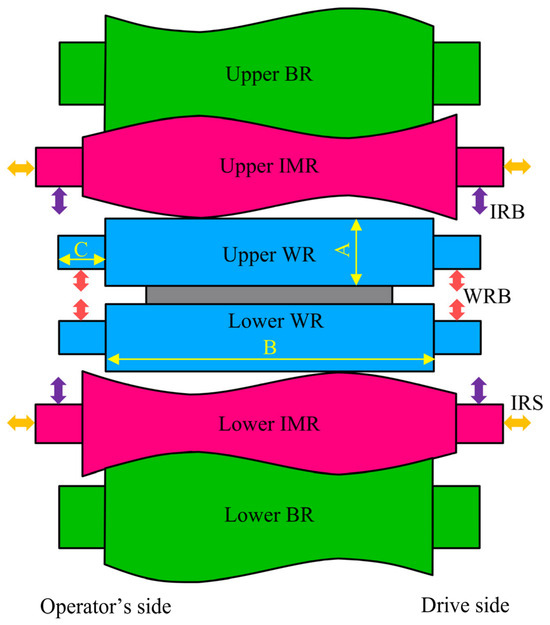
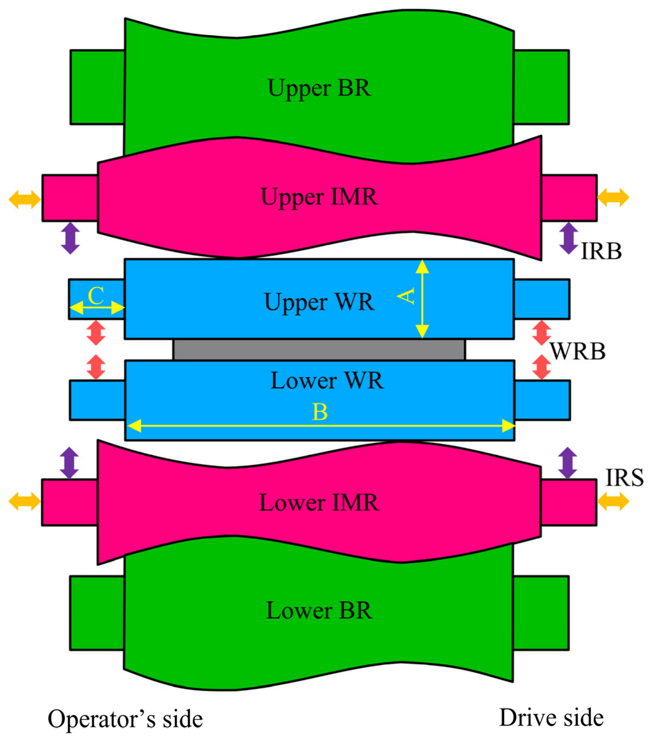
As displayed in Figure 1, the CVC-6 configuration denotes a six-high stand with upper and lower BRs, IMRs and WRs; the WR contour was conventional, the IMR contour was a third-order CVC curve and the BR contour was anti-CVC.
Figure 1.
Schematic diagram of the CVC-6 mill. A denotes barrel diameter; B denotes barrel length; and C denotes neck length.
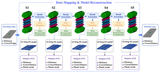
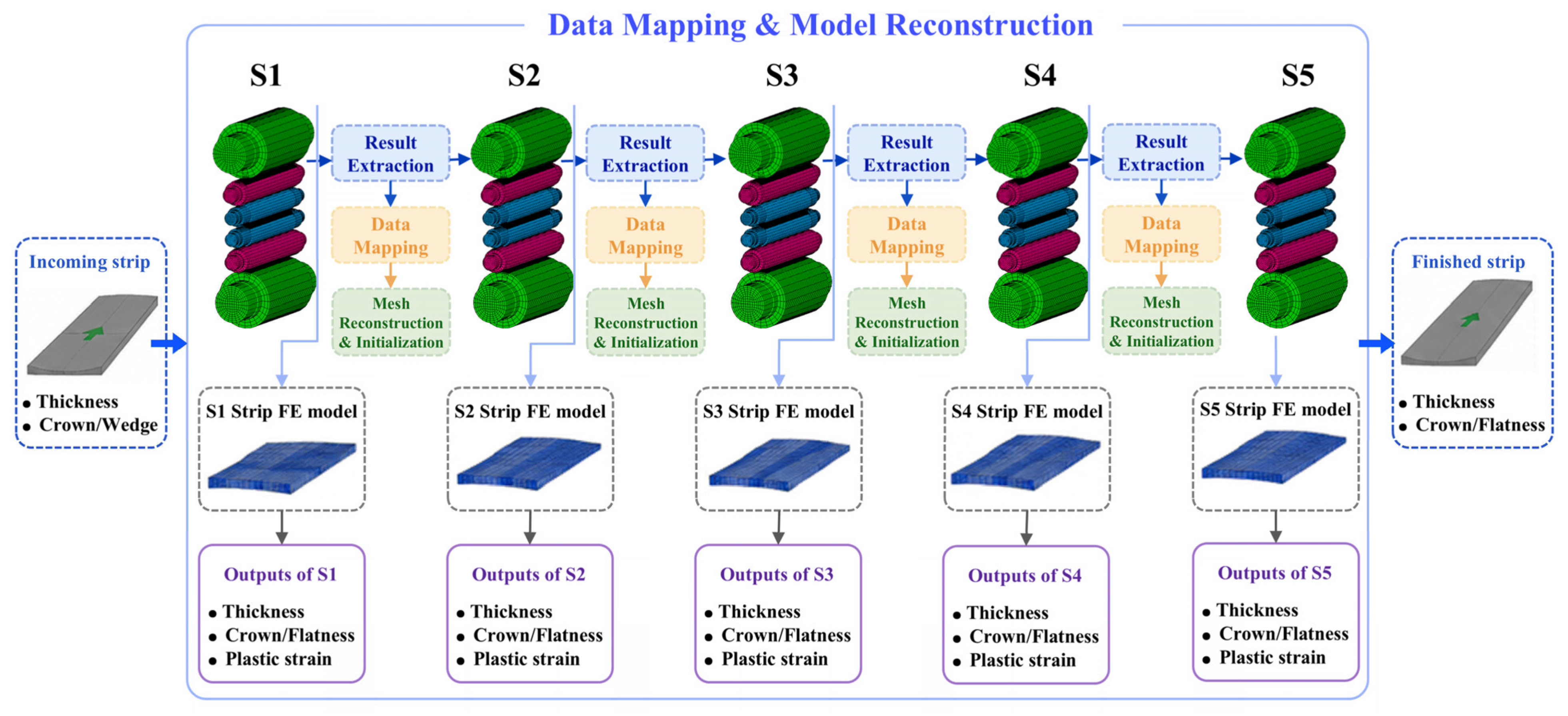
As shown in Figure 2, the five-stand tandem cold-rolling process was modeled by a segmentation strategy rather than by one excessively long FE model. Each stand was calculated as an individual 3D elastic–plastic rolling model, including the strip (in gray), WRs (in blue), IMRs (in red) and BRs (in green). After the strip left S1, the exit thickness profile, crown, flatness-related fiber elongation, and total equivalent plastic strain were extracted. These data were then mapped onto the entry strip of stand 2 (S2), and the same data-transfer operation was repeated from S2 to S5. During transfer, the severely elongated strip elements were reconstructed and re-meshed after each stand as a scheduled re-meshing step, not as an adaptive distortion trigger, so that the mesh became regular again in the rolling and width directions. This procedure follows the multi-stand cold-rolling modeling methods that preserve work hardening and strip crown inheritance between adjacent stands [15,16]. The roll-stack geometry, contact pairs, friction condition, tensions and actuator settings were assigned independently in each stand, while the inherited strip state was passed forward.
Figure 2.
Flowchart of the 3D multi-stand EPFE model calculation and data-transfer procedure.
2.2. Simulation Conditions
The strip was made of DC01 cold-rolled steel. In the EPFE model, the strip was treated as an elastic–plastic deformable body, whereas the rolls were assumed to exhibit linear elastic behavior. The physical and hardening parameters assigned to the strip and rolls were obtained from the authors’ previous study [16]. The main geometrical parameters of the rolls are listed in Table 1. The WR barrel length was 2180 mm, and the investigated widths of 900, 1200, 1500, 1800 and 2100 mm gave contact-span ratios W/LWR of 0.413, 0.550, 0.688, 0.826 and 0.963, respectively. The corresponding one-side unloaded WR shoulders were 640, 490, 340, 190 and 40 mm. Thus, the selected widths covered narrow, medium, wide and ultra-wide rolling conditions in the same industrial mill. The process schedule used in the five stands is listed in Table 2. To reveal the isolated width effect, the rolling speed, tensions, entry and exit thicknesses, IRS, IMB and WRB were kept unchanged for all strip width cases.
Table 1.
Geometrical parameters of the rolls.
Table 2.
Rolling process parameters for each stand.
The EPFE model used eight-node hexahedral solid elements rather than shell elements. Four solid-element layers were retained through the strip thickness in each stand so that thickness profile and local contact flattening could be evaluated directly. The strip mesh was refined near the strip edges and in the bite region, and the transverse mesh was regenerated for each width so that the edge, the center line and the positions 40 mm from both edges were always available by node extraction or interpolation. A representative single-stand model contained 214,808 elements.
The work-hardening state was updated stand by stand by transferring the total equivalent plastic strain to the next stand. The flow stress followed the DC01 hardening relation used in the validated model [16]. Therefore, the higher initial yield strength in the downstream stands was represented through the mapped plastic strain and the updated deformation resistance. The material was treated as isotropic because the objective was to isolate the width effect under one grade and one schedule. Possible rolling-texture anisotropy may influence absolute flatness values and is discussed as a limitation in Section 3.4.
Normal contact was defined for the strip–WR, WR–IMR and IMR–BR pairs. The rolling contact used the Coulomb bilinear friction model with a friction coefficient of 0.05 for all five stands, as in the published validation of the same 2180 mm tandem cold-rolling model [16]. The entry and exit tensions in Table 2 were applied as opposite uniform tensile stresses on the strip entry and exit end surfaces. As shown in Figure 1, the IRS values were imposed as axial displacements of the IMRs before rolling, whereas the IMB and WRB values were applied as symmetric bending force pairs at the corresponding roll necks. Roll rotation was assigned on the drive side of WRs at each stand.
The measurement points of strip cown, flatness, RDD and RFD of WR in the following figures were extracted from the transverse mesh nodes of each width case. For each strip width, the strip was uniformly discretized into 100 elements across the width, resulting in 101 nodal data points. All 101 data points were used to construct the curves. To avoid visual clutter and improve clarity, only a subset of data markers was displayed in the figures. Therefore, the apparently large and width-dependent spacing between the displayed markers does not represent the actual spacing or an uneven selection of the extracted data points.
The numerical accuracy of this modeling route was checked against published industrial data from the same 2180 mm tandem cold mill. As displayed in Table 3, the simulated rolling forces from S1 to S5 agreed with plant measurements with relative errors of less than 5% [17].
Table 3.
Measured and simulated rolling force for each stand.
2.3. Evaluation Indices
The relative thickness deviation (RTD) was used to describe the transverse profile of the strip, which can be described as Equation (1). A negative RTD near the strip edge corresponds to a positive strip crown, while a positive RTD near the edge indicates a negative strip crown.
where is the local strip thickness at transverse position , and is the center thickness.
The strip crown at 40 mm from the edge () was defined as Equation (2). The strip flatness was evaluated through the longitudinal fiber elongation difference, as shown in Equation (3). The calculated flatness curve was decomposed into Chebyshev components.
where and are the thicknesses at 40 mm from the strip edge on the drive side and operation side, respectively.
where represents the strip flatness value at the transverse position , expressed in international units (IU); is the longitudinal length of the strip fiber at the transverse position ; and denotes the mean length of all strip fibers across the strip width.
A quartic polynomial can be employed to describe the flatness curve, as shown in Equation (4), which can also be expressed using Chebyshev polynomials, as shown in Equation (5).
where , , , , and denote the coefficients; denotes the normalized width, from −1 to 1.
where , , , and denote the first flatness component, quadratic flatness component, cubic flatness component, and quartic flatness component, respectively, which can be expressed by Equations (6)–(9); denotes the error.
In this study, a positive corresponds to a center wave, and a negative corresponds to an edge wave. A positive corresponds to a quarter wave, and a negative corresponds to an edge–center coupled wave [29,30].
To interpret the strip crown and flatness results, two WR deformation indices were introduced. The relative deflection difference (RDD) is the sum of the upper and lower WR axis deflections at a transverse position minus the value at the strip center. The relative flattening difference (RFD) is the sum of the upper and lower WR flattening deformation in the WR–strip contact zone at a transverse position minus the value at the strip center. Their -type values, denoted as and , were used to compare the width sensitivity of WR axis deflection and local contact flattening. Their relative loaded roll-gap difference (RRD) is the loaded roll-gap at a transverse position minus the value at the WR center.
3. Results and Discussion
3.1. Effects of Strip Width on Strip Crown
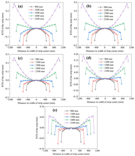
Figure 3 shows the RTD profiles of the strip for different strip widths from S1 to S5. The RTD profile changes systematically with width. For the 900 and 1200 mm strips, the edge region is generally thinner than the center, indicating a positive-crown strip. As the strip width increases to 1800 and 2100 mm, the RTD near the edge becomes positive in most stands, which means that the strip edge becomes thicker than the center. More specifically, Figure 3 shows that the 900 and 1200 mm strips maintain a relatively stable concave RTD near the edge, which corresponds to a positive strip crown. The 1500 mm strip is close to a transition state: the central region is still slightly thicker in some stands, but the edge upturn has already appeared. When the width increases to 1800 and 2100 mm, the edge RTD becomes obviously higher than that of the center, especially in S1–S4. This means that the loaded roll gap changes from center-open/edge-tight to edge-open/center-tight. Such a reversal cannot be explained by reduction alone because the reduction schedule is unchanged. It is a direct consequence of the changed roll-stack loading span.
Figure 3.
The RTD for different strip widths from S1 to S5: (a) S1; (b) S2; (c) S3; (d) S4; and (e) S5.
The most important feature shown in Figure 3 is the profile reversal between the medium-width and ultra-wide cases. The 1500 mm strip is close to the transition condition, while the 1800 and 2100 mm strips show a clear tendency toward negative strip crown. This indicates that the width effect is not a simple proportional scaling of the same profile. Instead, the transverse load span changes the deformation mode of the roll stack and shifts the loaded roll gap from an edge-thinning state to an edge-thickening state.
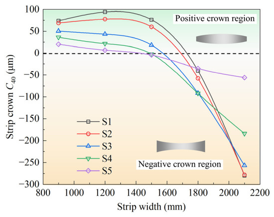
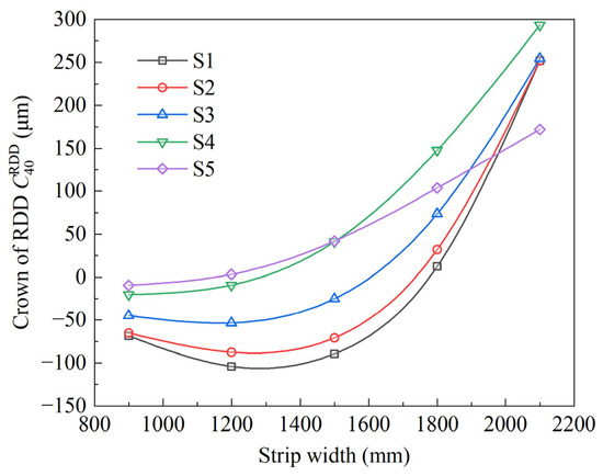
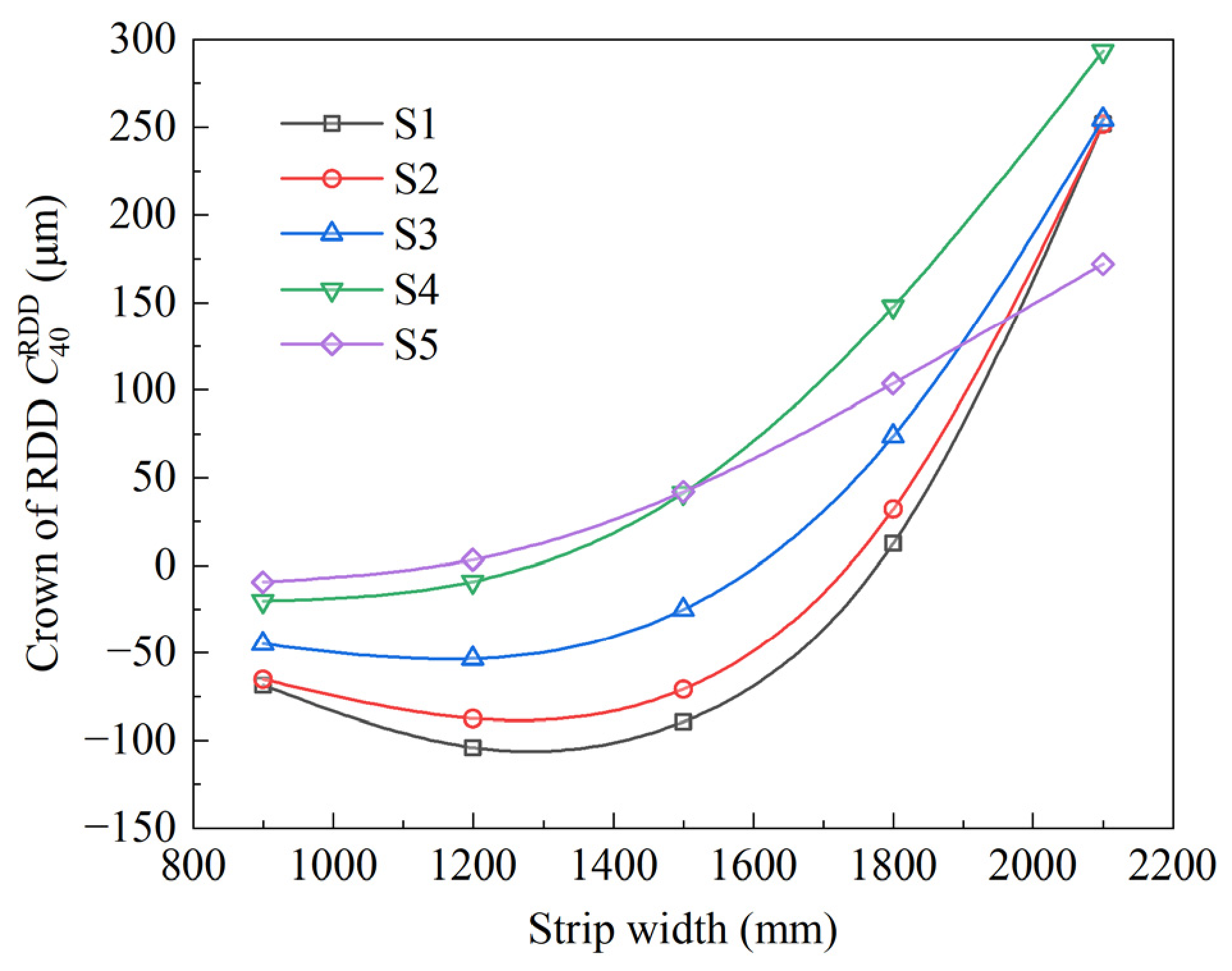
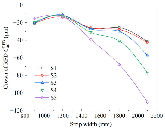
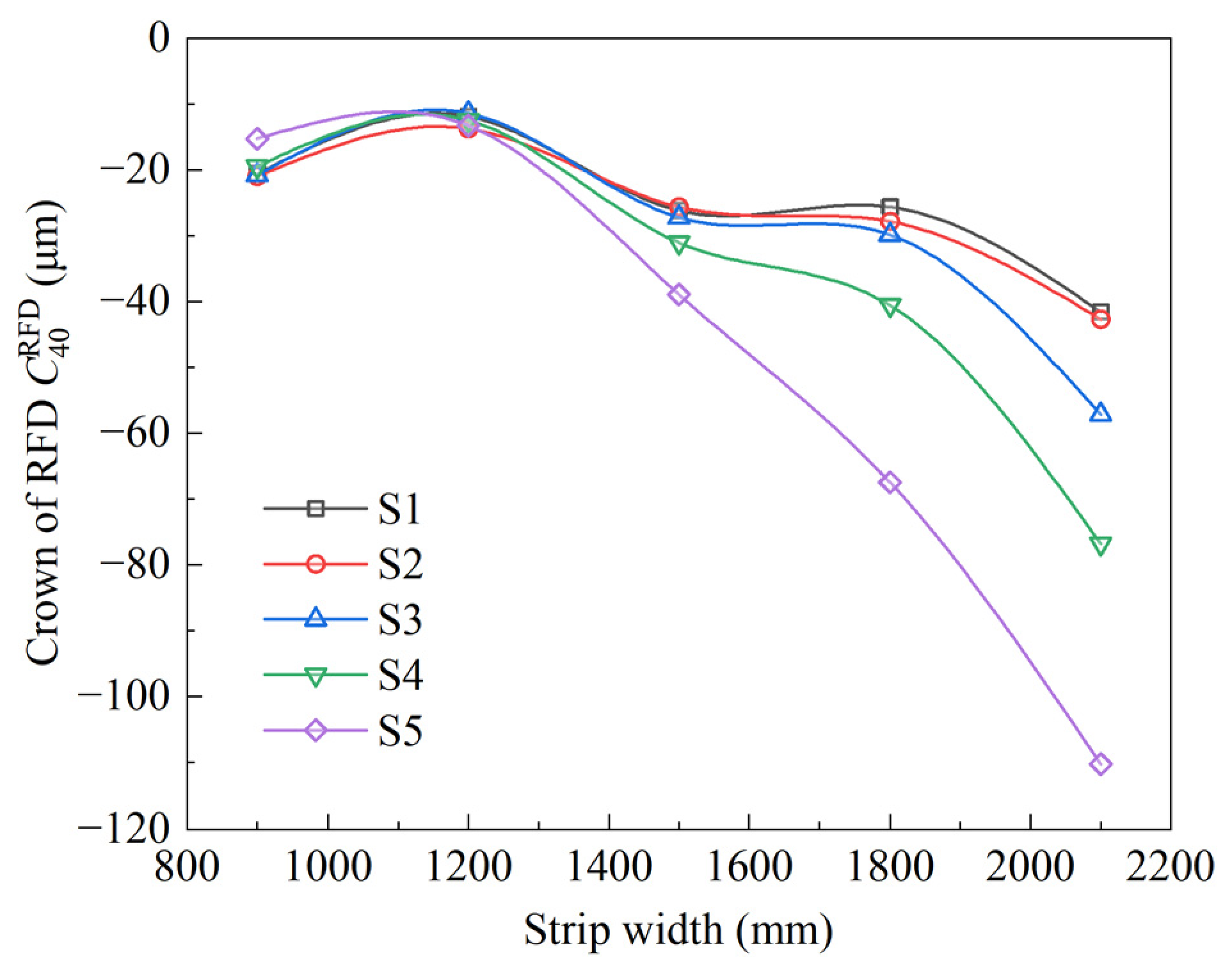
Figure 4 compares the variation in with strip width from S1 to S5. In all stands, decreases as the strip width increases. More precisely, when the strip width increases from 900 mm to 2100 mm, decreases from 20~80 μm to −50~−280 μm. The positive crown obtained at narrow and medium strip widths gradually disappears, and becomes negative when the strip width is sufficiently large. Figure 4 further quantifies the profile reversal. Below 1500 mm, is generally positive in the upstream and middle stands, whereas the 1800 and 2100 mm cases enter the negative-crown region. The sharp drop between 1500 and 2100 mm indicates that the strip width effect becomes nonlinear when the strip edge approaches the roll barrel end. This trend differs from the rolling-force effect reported in tandem cold rolling, where changing rolling force modifies the magnitude of WR deflection and flattening with an approximately fixed contact span [15]. In the present work, the total contact span itself changes, so the transverse location of the load becomes the dominant factor.
Figure 4.
The strip crown efficiency curves.
The stand dependence shown in Figure 4 is also instructive. S1–S3 show a large crown decrease with increasing strip width, while S5 presents a milder variation. This does not mean that the downstream stand is unimportant. The downstream strip has higher plastic rigidity because of accumulated work hardening, and previous crown inheritance analysis showed that downstream stands can inherit profile disturbances more strongly [16]. Therefore, a relatively small strip crown change in S5 can still be important for final product shape, especially when it is accompanied by center-wave flatness.
The reduction in with increasing strip width can be explained by the contact-span ratio. When the strip is narrow, the rolling load is concentrated around the roll center and a relatively large, unloaded shoulder remains on each side of the WR barrel. The roll-stack deformation under this condition produces a loaded roll gap in which the edge is relatively tighter than that of the center, resulting in positive strip crown. When the width approaches the WR barrel length, the rolling load extends toward the roll barrel end. The edge region then becomes more sensitive to WR axis deflection, and the loaded roll gap opens near the strip edge. As a result, the strip edge becomes thicker, and decreases into the negative range.
The stand-to-stand difference is also meaningful. The upstream stands still have a relatively thick strip and lower plastic rigidity, so the strip can accommodate part of the roll-gap difference through transverse metal flow and plastic deformation. In the downstream stands, the strip is thinner and stiffer in the transverse profile-control sense, so a similar roll-gap disturbance is more directly inherited as exit crown and flatness. This agrees with crown inheritance analysis showing that the inheritance factor is linked to the strip plastic rigidity [16]. It is also consistent with roll-bending research, where actuator regulation ability changes from stand to stand as strip plastic rigidity evolves [18].
Quantitatively, the change from W/LWR = 0.688 at 1500 mm to W/LWR = 0.826 at 1800 mm is the important transition interval in this mill. The one-side unloaded shoulder decreases from 340 mm to 190 mm in this interval, so the loaded strip edge begins to interact more strongly with the roll-end compliance. This explains why crosses from the positive-crown region into the negative-crown region around 1800 mm. The critical value is, therefore, not a universal width; it corresponds to a contact-span ratio of about 0.83 for the investigated 2180 mm CVC-6 mill and should be re-evaluated for mills with a different barrel length, roll contour or actuator sign convention.
3.2. Effects of Strip Width on Strip Flatness
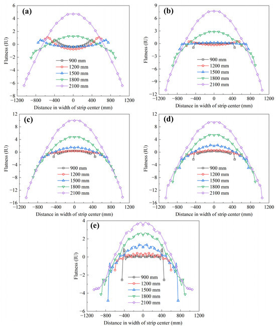
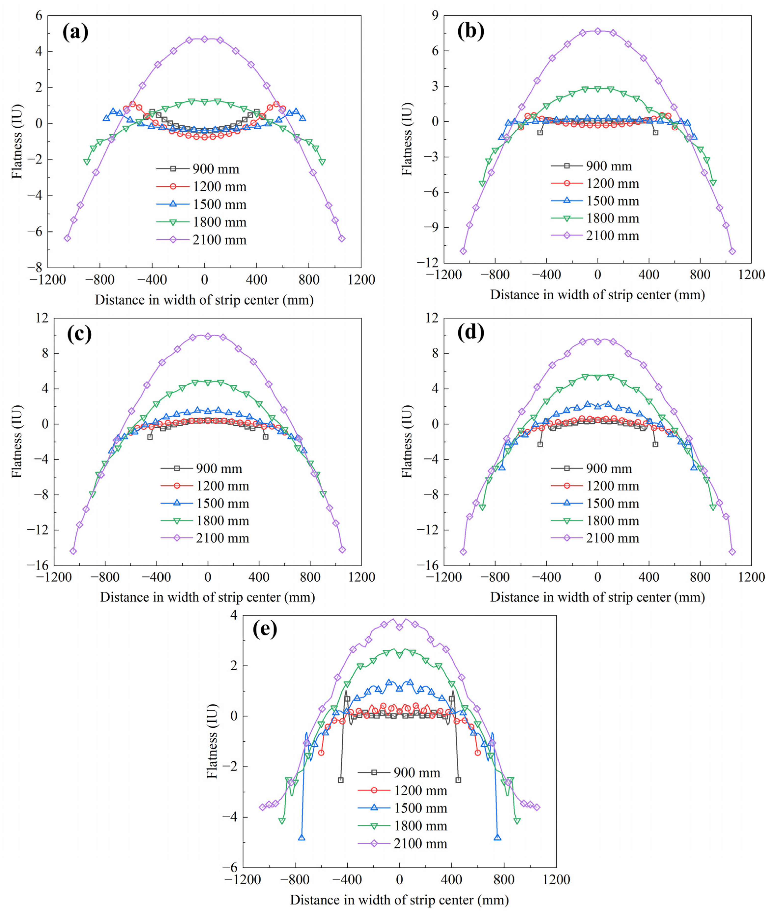
Figure 5 displays the calculated flatness profiles for different strip widths. The flatness distribution is non-uniform in the width direction in all stands, and the non-uniformity increases as the strip width becomes larger. The flatness profiles shown in Figure 5 are consistent with the crown evolution. For narrow strips, the flatness amplitude is limited, and the curve shape is relatively smooth. For 1800 and 2100 mm strips, the center region shows larger positive elongation difference in several stands, while the strip edge and quarter-width regions deviate in the opposite direction. This indicates that the negative-crown tendency does not remain a purely geometric thickness defect; it is transformed into non-uniform longitudinal elongation. The transformation is more evident in the later stands because the strip plastic rigidity is higher and lateral flow cannot fully relax the imposed roll-gap difference.
Figure 5.
Strip flatness for different strip widths from S1 to S5: (a) S1; (b) S2; (c) S3; (d) S4; and (e) S5.
For narrow strips, the flatness profile is relatively mild because the strip edge is far from the roll barrel end and the lateral spread near the free edge can partly relax the longitudinal elongation difference. For ultra-wide strips, the edge is close to the roll barrel end, and the width direction is more strongly constrained by the loaded roll gap. The non-uniform elongation, therefore, becomes more pronounced, especially in the center and quarter-width regions.
The apparent difference between S3–S4 and S5 in Figure 4 can be understood from the combined effects of accumulated work hardening, final thickness and tension. Although the S5 thickness reduction is small, the strip entering S5 has already accumulated the plastic strain from S1–S4 and, therefore, has higher deformation resistance and higher transverse profile rigidity. In addition, the S5 exit tension is only 40 kN, much lower than that in the preceding stands. Under this condition, the inherited loaded-gap non-uniformity is less easily relaxed by lateral flow and becomes more visible as longitudinal elongation difference. Thus, a small final reduction can still produce a marked flatness response.
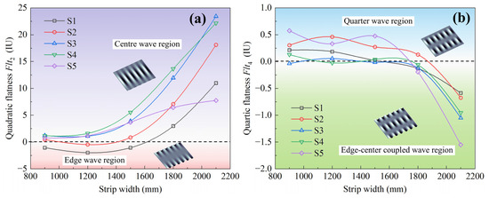
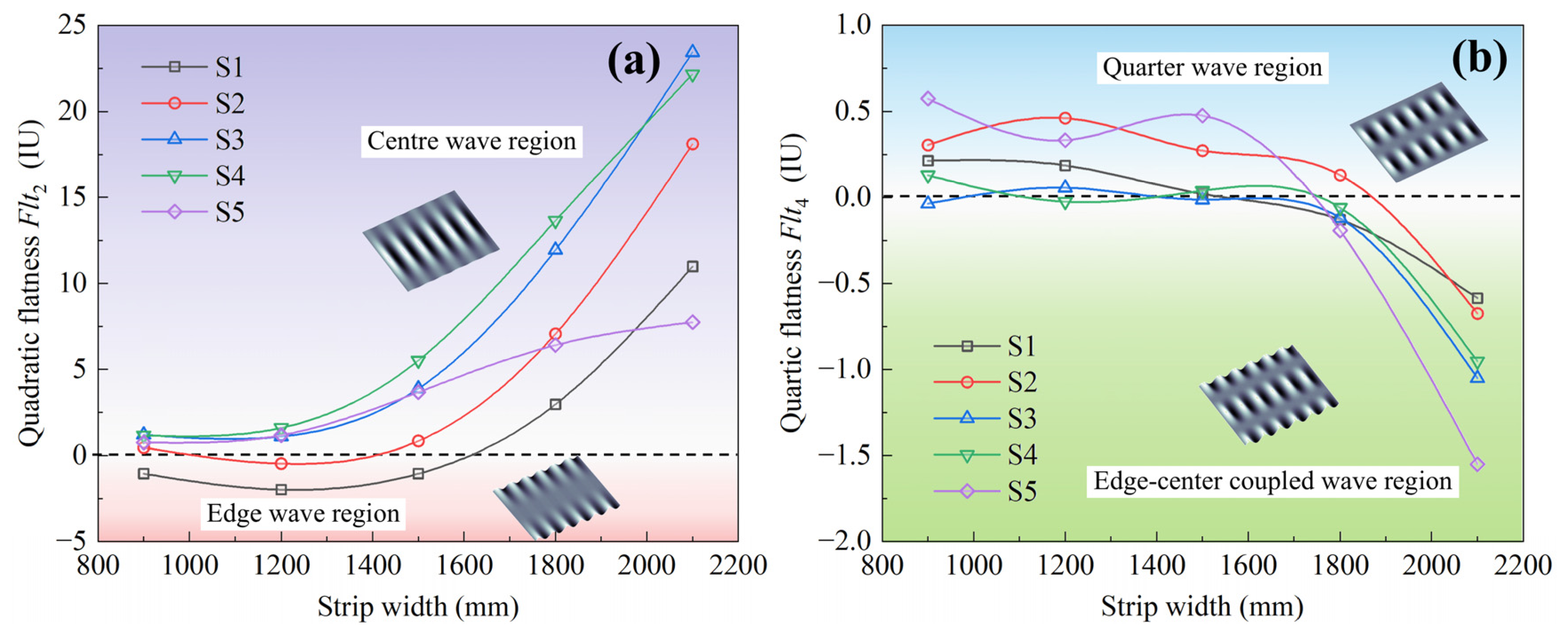
Figure 6 summarizes the width effect on the quadratic flatness and quartic flatness . increases with strip width in most stands, indicating a strengthened center-wave tendency. In contrast, decreases and becomes negative for wide strips, indicating a transition toward an edge–center coupled wave. Figure 6a shows that increases with width in almost all stands. Since a positive represents a center wave in the Chebyshev description, the ultra-wide cases are more likely to produce center-wave flatness. Figure 6b shows a different trend for : the value decreases as width increases and becomes negative for wide strips, indicating an edge–center coupled wave. This separation between and is important. It shows that the strip width affects not only the average crown level, but also the high-order shape mode. The use of Chebyshev components for flatness evaluation is consistent with the flatness control framework proposed for rolling process chains [29,30].
Figure 6.
The efficiency curves of the strip width vs. (a) and (b).
The width-induced increase in can be compared with previous studies on lateral metal flow. Wang et al. [22] showed that the non-uniform lateral metal flow can change longitudinal elongation and cause flatness defects. In the present cold-rolling model, lateral flow is limited by low temperature and by work hardening. Therefore, when an ultra-wide strip produces an edge-open loaded roll gap, the center region tends to elongate more instead of being fully compensated by transverse flow. This explains why the center-wave flatness strengthens with increasing width.
The simultaneous increase in and decrease in indicates that the strip width effect changes the mode of flatness defect rather than merely increasing its amplitude. The negative strip crown generated in the ultra-wide cases reduces the center thickness relative to the edge. Under the same exit thickness schedule, this profile promotes larger longitudinal elongation in the center region and, thus, strengthens the center-wave component. At the same time, the different deformation compatibility among the center, quarter and edge regions causes to shift toward the edge–center coupled wave.
This mechanism is consistent with the relationship between loaded roll gap and flatness. Previous studies showed that the quadratic crown of the loaded roll gap is generally opposite to quadratic flatness, while the quartic crown is related to the quartic flatness mode [22,31]. In the present ultra-wide cases, the width-induced loaded-gap change, therefore, appears in both and the Chebyshev flatness components.
3.3. Effects of Strip Width on Elastic Deformation of WR
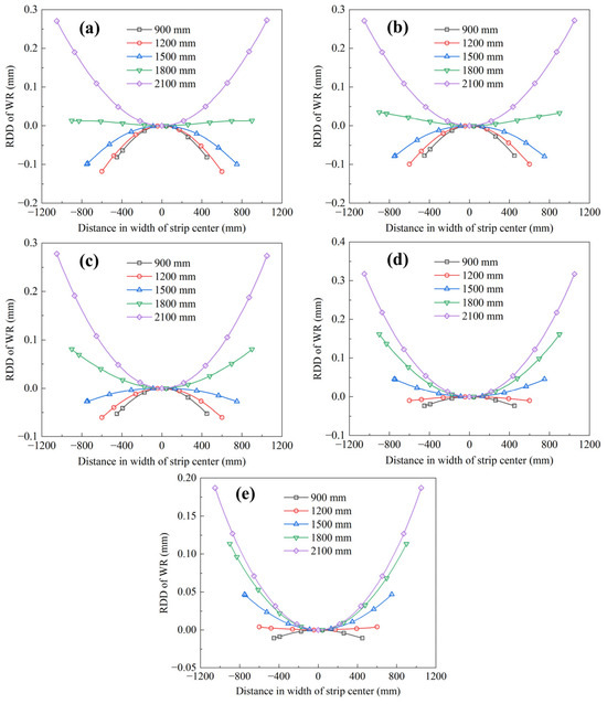
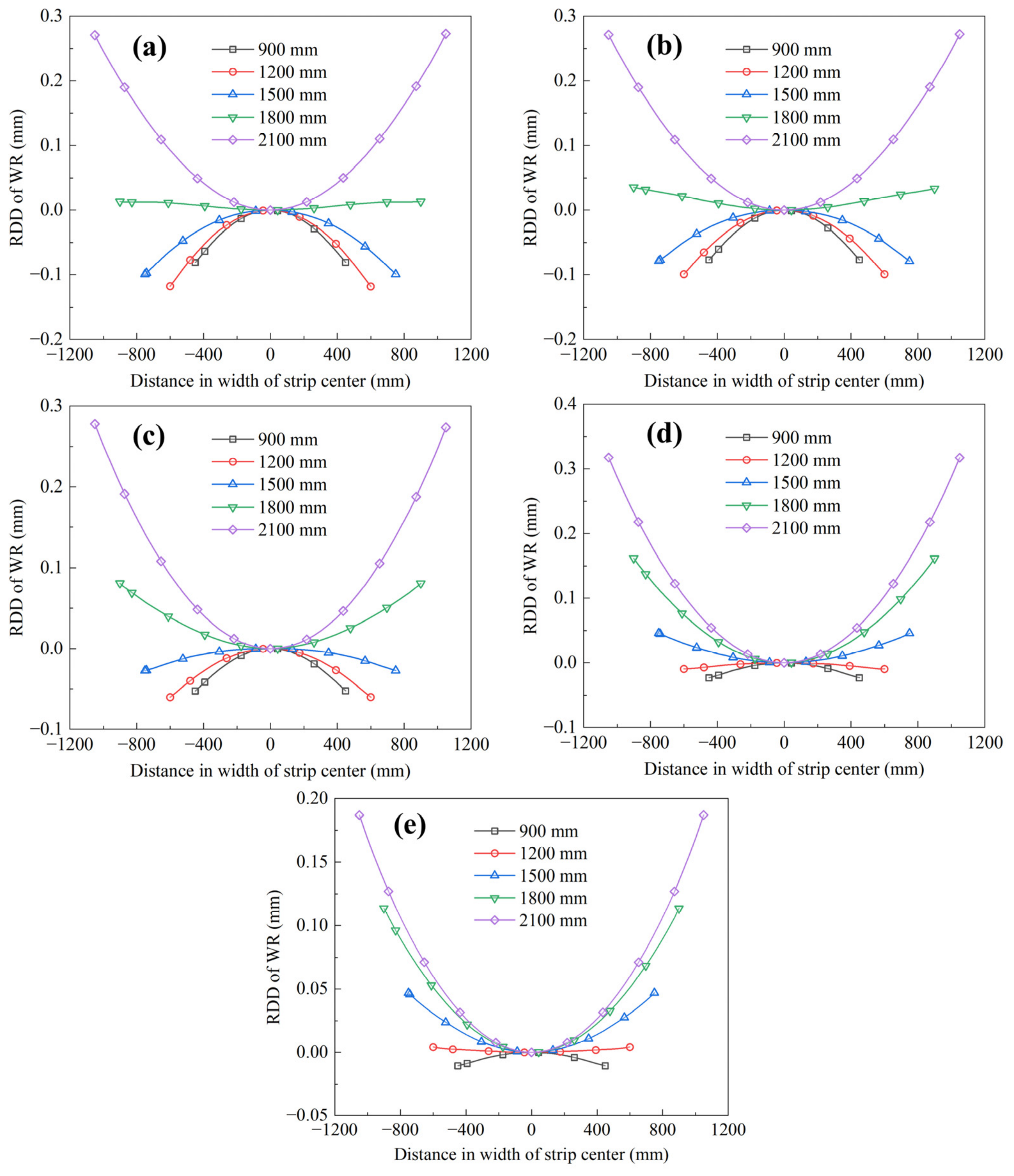
Figure 7 shows the RDD of the WRs with different strip widths, which reveals the first part of the mechanism. The RDD curve becomes more concave upward as the strip width increases, and the edge value rises rapidly for the 1800 and 2100 mm cases. This means that the WR axis deflection near the strip edge increases relative to the center. In a narrow strip, the roll body outside the strip still provides a large, unloaded shoulder, and the strip load is far from the barrel end. In an ultra-wide strip, this shoulder becomes very small, so the edge region of the loaded roll gap is more strongly affected by roll-end compliance.
Figure 7.
The RDD of WR with various strip widths from S1 to S5: (a) S1; (b) S2; (c) S3; (d) S4; and (e) S5.
The RDD profiles demonstrate that the WR axis deformation is highly sensitive to contact width. For narrow strips, the loaded zone is concentrated around the roll center, and the relative edge deflection is limited. With increasing strip width, the loaded zone extends toward the barrel end, and the relative edge deflection increases sharply. This deformation trend directly supports the crown reversal observed in Figure 3 and Figure 4.
Figure 8 shows the variation in with strip width from S1 to S5. changes from negative or weakly positive values at narrow widths to large positive values at ultra-wide widths. The trend of shown in Figure 8 agrees well with the strip crown trend shown in Figure 4. When the strip width increases beyond 1500 mm, rises quickly in S1–S4, which means that the deflection component tends to open the loaded roll gap at 40 mm from the edge. This is the mechanical reason why decreases and eventually becomes negative. Roll-bending studies have also reported that the WR deflection is the dominant factor controlling the strip shape in upstream stands [18]. The present results extend that conclusion by showing that the strip width can change WR deflection even when the bending force is unchanged.
Figure 8.
The efficiency curves of the strip width vs. the .
The rapid increase in indicates that the strip width mainly affects the strip crown through a change in the WR bending mode. When the strip becomes ultra-wide, the edge load is no longer a local perturbation; it becomes part of the main bending span of the roll stack. Consequently, the edge region of the loaded roll gap opens relative to the center, which is favorable for negative crown formation.
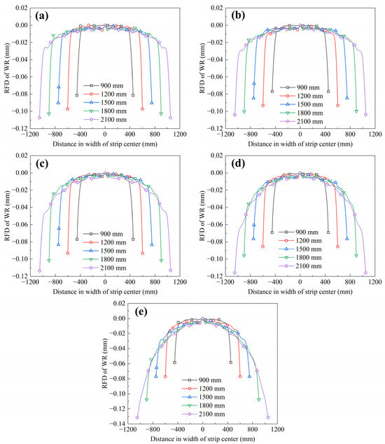
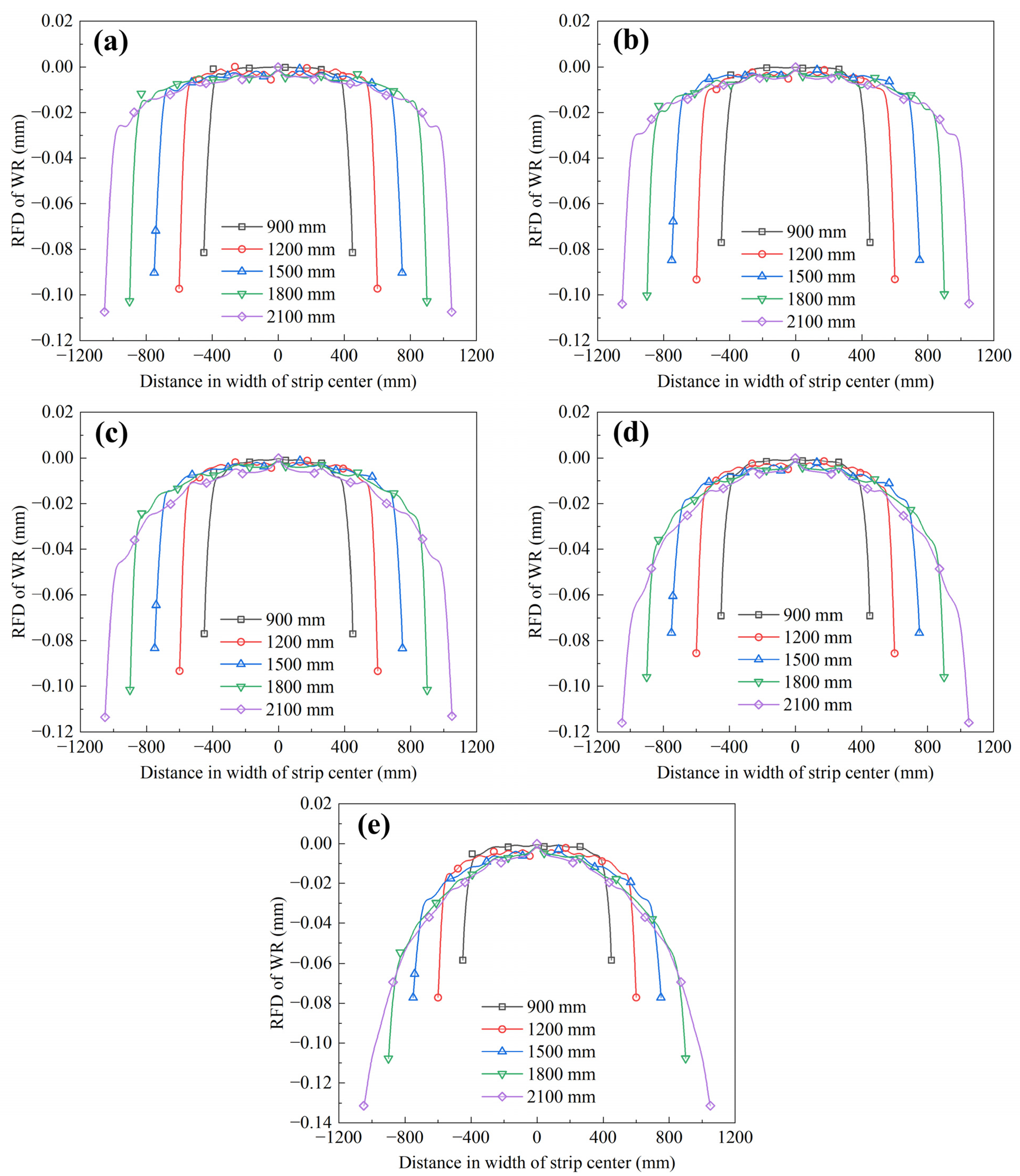
Figure 9 compares the RFD of WRs for different strip widths, which gives the second part of the mechanism. Unlike the RDD curves, the RFD curves remain negative near the edge. This indicates that local WR flattening is still greater around the strip center than that near the strip edge. Therefore, the flattening component tends to close the center gap relative to the edge, while the deflection component tends to open the edge gap. The final loaded roll gap is determined by the competition between these two components.
Figure 9.
The RFD of WR with various strip widths from S1 to S5: (a) S1; (b) S2; (c) S3; (d) S4; and (e) S5.
The RFD profiles are different from the RDD profiles. The flattening deformation is greatest near the center and decreases toward the strip edge, especially for wide and ultra-wide strips. This means that the local roll–strip contact compliance does not increase uniformly with width. The edge contact zone, although closer to the roll barrel end, still has less local flattening than the center because the pressure distribution and adjacent free-edge condition are different.
Figure 10 shows the variation in with strip width. remains negative, and its magnitude increases with width, especially in the downstream stands. Figure 10 shows that becomes more negative with increasing strip width, especially in S4 and S5. At first glance, this seems opposite to the positive-crown trend shown in Figure 4. The apparent contradiction is resolved by considering the relative strength of the two components. The increase in shown in Figure 8 is large enough to dominate the loaded roll-gap change, while the negative represents a partial compensation rather than the controlling effect. This is consistent with the conclusion from roll-bending research that deflection and flattening jointly determine the downstream shape, but the deflection often remains the leading factor [18].
Figure 10.
The efficiency curves of the strip width vs. the .
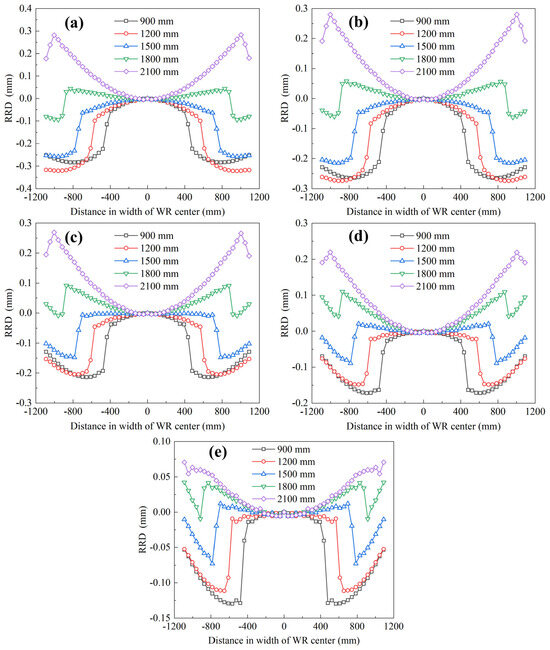
Combining Figure 7, Figure 8, Figure 9 and Figure 10 gives the key mechanism of the strip width effect. Increasing the strip width simultaneously increases the relative WR axis deflection near the strip edge and enlarges the non-uniformity of local WR flattening. The strip crown and flatness are determined by the balance between these two deformation components. For the ultra-wide strip cases, the deflection component grows faster and dominates the loaded roll-gap profile, while the flattening component is insufficient to compensate for the edge opening. This produces negative RDD (as shown in Figure 11) and, thus, strip crown and promotes center-wave flatness. Therefore, the strip-width-adaptive shape preset should not use a single strip crown target for all products. For strips wider than approximately 1800 mm in this mill, the preset values of the WRB, IMB and IRS should be corrected to avoid over-opening the edge region of the loaded roll gap.
Figure 11.
The RRD with various strip widths from S1 to S5: (a) S1; (b) S2; (c) S3; (d) S4; and (e) S5.
The competition can be quantified by comparing the 40 mm edge indices in Figure 8 and Figure 10. When the width increases to 2100 mm, becomes strongly positive in S1-S4, reaching roughly 250~295 μm, whereas remains negative and provides only partial compensation, with values of about −40 to −110 μm depending on the stand. The sign of the summed roll-gap effect is, therefore, controlled by the deflection term for ultra-wide strips. This quantitative imbalance supports the proposed mechanism that WR axis deflection, rather than local flattening alone, is responsible for the edge-open loaded roll gap.
3.4. Influence Mechanism and Industrial Implications
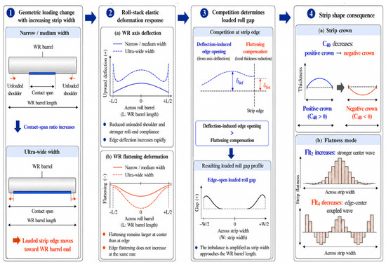
The above results can be summarized by the mechanism shown in Figure 12. Increasing the strip width first increases the contact-span ratio and moves the loaded strip edge toward the WR barrel end. This geometrical change modifies the roll-stack boundary condition. The WR axis deflection near the strip edge then increases rapidly, while the local WR flattening remains center-dominant. When the deflection-induced edge opening is larger than that of the flattening compensation, the loaded roll gap changes toward an edge-open profile, as shown in Figure 11. The strip crown consequently decreases from positive to negative, and the corresponding elongation difference promotes the center-wave flatness and edge–center coupled wave.
Figure 12.
Mechanism of the strip-width effect on strip shape in ultra-wide-strip tandem cold rolling.
From a production viewpoint, the main implication is that width should be included explicitly in the shape preset model. For strips wider than about 1800 mm in the studied mill, directly applying medium-width WRB, IMB and IRS presets may over-open the edge region of the loaded roll gap and increase the risk of the negative strip crown and center wave. The actuator correction should be selected according to the mill sign convention, but the control target is clear: compensate for the width-induced increase in and keep the loaded roll gap from becoming edge-open. In practice, this can be achieved by building width-dependent crown compensation tables, checking as a warning index for the center-wave formation, and applying smoother actuator transitions when the schedule changes from medium-width to ultra-wide products.
A width-adaptive preset can be implemented by adding a width correction layer to the existing setup model. First, the contact-span ratio W/LWR is calculated from the scheduled strip width. Second, when the W/LWR approaches or exceeds the transition value of about 0.83 in this mill, the preset model should apply correction coefficients for WRB, IMB and IRS to reduce the positive contribution and restore the target loaded roll gap. Third, and can be used as monitoring indices: a rising warns of a center-wave tendency, while a negative warns of an edge–center coupled wave. The actual sign and magnitude of the WRB, IMB and IRS corrections should be calibrated from plant actuator efficiency tests because they depend on roll contour, bearing constraints and the mill sign convention.
The generalizability of the results should also be interpreted with these constraints in mind. The transition width of about 1800 mm is specific to the present 2180 mm CVC-6 mill, DC01 material, reduction schedule, friction coefficient and actuator settings. Other strip grades, roll contours, lubrication states or mill stiffnesses may shift the transition to a different contact-span ratio. The isotropic hardening assumption and the lack of direct plant validation for every width case are additional limitations. Nevertheless, because all width cases were simulated with the same validated modeling framework and with all non-width parameters fixed, the relative trends and the identified competition between WR axis deflection and WR flattening are expected to be transferable to other ultra-wide tandem mills after recalibration.
4. Conclusions
(1) When the width-to-WR barrel ratio increases from 0.413 at 900 mm to 0.963 at 2100 mm (the one-side-unloaded shoulder decreases from 640 mm to 40 mm), the strip crown decreases from 20~80 μm to −50~−280 μm. The 900–1500 mm cases remain mainly in the positive-crown region, whereas the 1800–2100 mm cases enter the negative-crown region. In the studied mill, the transition occurs at about W/LWR = 0.83, corresponding to a strip width of approximately 1800 mm.
(2) Strip width changes the flatness mode. With increasing width, the quadratic flatness component increases and reaches the center-wave region for wide and ultra-wide strips, whereas the quartic component decreases and becomes negative, indicating an edge–center coupled-wave mode.
(3) The mechanism is governed by the competition between the WR axis deflection and WR flattening. For the 2100 mm strip, reaches approximately 250~295 μm in the main stands, while remains negative at about −40 to −110 μm. The deflection-induced edge opening, therefore, dominates the local flattening compensation and changes the loaded roll gap toward an edge-open profile.
(4) For ultra-wide strips, width should be included as an independent preset variable in strip shape control. In the studied mill, strips wider than about 1800 mm require actuator corrections that compensate for the width-induced increase in edge opening of the loaded roll gap. The combined monitoring of the contact-span ratio, , , , and can provide a practical basis for strip-width-adaptive WRB, IMB and IRS presets.
Author Contributions
Conceptualization, X.W.; methodology, L.L. and T.L. (Teng Li); validation, H.C. and T.L. (Teng Li); formal analysis, H.X. and H.T.; investigation, L.L., H.C. and X.L.; resources, H.L., K.C. and C.Z.; data curation, H.X., X.L., T.L. (Tianwu Liu), K.C. and C.Z.; writing—original draft preparation, L.L.; writing—review and editing, Z.J.; visualization, T.L. (Tianwu Liu); supervision, L.S. and Z.J.; project administration, H.L., X.W., L.S. and Z.J. All authors have read and agreed to the published version of the manuscript.
Funding
This research was funded by HBIS (China) (grant number HG2024146), and ARC ITTC for Innovative Composites for the Future of Sustainable Mining Equipment (grant number IC220100028).
Data Availability Statement
The original contributions presented in this study are included in the article. Further inquiries can be directed to the corresponding authors.
Acknowledgments
The authors thank the technicians of the China–Serbia Belt and Road Joint Laboratory on Green Steel Manufacturing for their assistance in this work.
Conflicts of Interest
Author Chuanbao Zheng was employed by the company Hengshui Board Packaging Materials Technology Co., Ltd., Author Kai Chen was employed by the Changshu Kehong Materials Technology Co., Ltd. The remaining authors declare that the research was conducted in the absence of any commercial or financial relationships that could be construed as a potential conflict of interest.
References
- Stone, M.D.; Gray, R. Theory and practical aspects in crown control. Iron Steel Eng. 1965, 8, 73–90. [Google Scholar]
- Shohet, K.N.; Townsend, N.A. Roll bending methods of crown control in four-high plate mills. J. Iron Steel Inst. 1968, 206, 1088–1098. [Google Scholar]
- Ginzburg, V.B. High-Quality Steel Rolling: Theory and Practice; CRC Press: New York, NY, USA, 1993. [Google Scholar]
- Bald, W.; Beisemann, G.; Feldmann, H.; Schultes, T. Continuously variable crown (CVC) rolling. Iron Steel Eng. 1987, 64, 32–41. [Google Scholar]
- Kawanami, T.; Asamura, T.; Matsumoto, H. Development of high-precision shape and crown control technology for strip rolling. J. Mater. Process. Technol. 1990, 22, 257–275. [Google Scholar] [CrossRef] [Scilit]
- Guo, R.-M. Characteristics of Rolling Mills with Roll Shifting. Iron Steel Technol. 1988, 65, 45–54. [Google Scholar]
- Yuan, T.; Sun, W.; Sun, T.; Qie, H.; Jiang, M.; Yang, T.; Liu, C. Roll profile and roll shifting strategy for silicon steel edge drop control in cold rolling CVC mill. J. Manuf. Process. 2024, 124, 80–89. [Google Scholar] [CrossRef] [Scilit]
- Jiang, Z.Y.; Zhu, H.T.; Tieu, A.K. Mechanics of roll edge contact in cold rolling of thin strip. Int. J. Mech. Sci. 2006, 48, 697–706. [Google Scholar] [CrossRef] [Scilit]
- Jiang, Z.Y.; Tieu, A.K. A 3-D finite element method analysis of cold rolling of thin strip with friction variation. Tribol. Int. 2004, 37, 185–191. [Google Scholar] [CrossRef] [Scilit]
- Liu, X.H.; Shi, X.; Li, S.Q.; Xu, J.Y.; Wang, G.D. FEM analysis of rolling pressure along strip width in cold rolling process. J. Iron Steel Res. Int. 2007, 14, 22–26. [Google Scholar] [CrossRef] [Scilit]
- Sun, J.N.; Du, F.S.; Li, X.T. FEM simulation of the roll deformation of six-high CVC mill in cold strip rolling. In Proceedings of the 2008 International Workshop on Modelling, Simulation and Optimization, Hong Kong, China, 27–28 December 2008; pp. 412–415. [Google Scholar]
- Linghu, K.Z.; Jiang, Z.Y.; Zhao, J.W.; Li, F.; Wei, D.B.; Xu, J.Z.; Zhang, X.M.; Zhao, X.M. 3D FEM analysis of strip shape during multi-pass rolling in a 6-high CVC cold rolling mill. Int. J. Adv. Manuf. Technol. 2014, 74, 1733–1745. [Google Scholar] [CrossRef] [Scilit]
- Wang, Q.L.; Sun, J.; Liu, Y.M.; Wang, P.F.; Zhang, D.H. Analysis of symmetrical flatness actuator efficiencies for UCM cold rolling mill by 3D elastic–plastic FEM. Int. J. Adv. Manuf. Technol. 2017, 92, 1371–1389. [Google Scholar] [CrossRef] [Scilit]
- Wang, Q.L.; Sun, J.; Li, X.; Liu, Y.M.; Wang, P.F.; Zhang, D.H. Numerical and experimental analysis of strip cross-directional control and flatness prediction for UCM cold rolling mill. J. Manuf. Process. 2018, 34, 637–649. [Google Scholar] [CrossRef] [Scilit]
- Li, L.J.; Xie, H.B.; Liu, T.W.; Li, X.S.; Liu, X.; Huo, M.S.; Wang, E.R.; Li, J.X.; Liu, H.Q.; Sun, L.; et al. Effects of rolling force on strip shape during tandem cold rolling using a novel multistand finite element model. Steel Res. Int. 2021, 93, 2100359. [Google Scholar] [CrossRef] [Scilit]
- Li, L.J.; Xie, H.B.; Liu, T.W.; Huo, M.S.; Li, X.S.; Liu, X.; Wang, E.R.; Li, J.X.; Liu, H.Q.; Sun, L.; et al. Numerical analysis of the strip crown inheritance in tandem cold rolling by a novel 3D multi-stand FE model. Int. J. Adv. Manuf. Technol. 2022, 120, 3683–3704. [Google Scholar] [CrossRef] [Scilit]
- Li, L.J.; Xie, H.B.; Zhang, T.; Pan, D.; Li, X.S.; Chen, F.H.; Liu, X.; Liu, H.Q.; Sun, L.; Jiang, Z.Y. Influence of intermediate roll shifting on strip shape in a CVC-6 tandem cold mill based on a 3D multi-stand FE model. Int. J. Adv. Manuf. Technol. 2022, 121, 4367–4385. [Google Scholar] [CrossRef] [Scilit]
- Li, L.J.; Xie, H.B.; Zhang, T.; Huo, M.S.; Pan, D.; Wu, H.; Chen, F.H.; Liu, T.W.; Li, X.S.; Liu, X.; et al. Understanding the regulation ability of roll bending on strip shape in a CVC-6 tandem cold mill using a 3D multiple stand FE model. J. Manuf. Process. 2023, 101, 1013–1031. [Google Scholar] [CrossRef] [Scilit]
- Li, X.; Li, X.; Wang, Q.; Han, Y.; Wang, P.; Zhang, X.; Zhang, Y. Mathematical modeling and numerical experiments for strip shape prediction in tandem cold rolling. Int. J. Adv. Manuf. Technol. 2025, 140, 1841–1859. [Google Scholar] [CrossRef] [Scilit]
- Li, X.; Li, X.; Wang, Q.; Cao, L.; Yuan, H. Rolled-flatness deviation evolution mechanism induced by transverse inhomogeneous deformation resistance during tandem cold rolling. J. Manuf. Process. 2025, 151, 24–40. [Google Scholar] [CrossRef] [Scilit]
- Li, X.; Li, X.; Han, Y.; Jin, S.; Wang, P.; Zhang, X.; Zhang, Y. Influence of transverse property differences in hot-rolled high-strength strip on cold rolling deformation behavior. Int. J. Adv. Manuf. Technol. 2025, 138, 2491–2509. [Google Scholar] [CrossRef] [Scilit]
- Wang, Q.L.; Sun, J.; Li, X.; Wang, Z.H.; Wang, P.F.; Zhang, D.H. Analysis of lateral metal flow-induced flatness deviations of rolled steel strip: Mathematical modeling and simulation experiments. Appl. Math. Model. 2020, 77, 289–308. [Google Scholar] [CrossRef] [Scilit]
- Wang, Q.L.; Li, X.; Sun, J.; Liu, Y.M.; Zhang, X.C.; Wang, Z.Q. Mathematical and numerical analysis of cross-directional control for SmartCrown rolls in strip mill. J. Manuf. Process. 2021, 69, 451–472. [Google Scholar] [CrossRef] [Scilit]
- Li, L.J.; Xie, H.B.; Zhang, T.; Pan, D.; Liu, T.W.; Li, X.S.; Liu, X.; Wang, E.R.; Liu, H.Q.; Sun, L.; et al. Influences of thermal crown and wear crown of work roll on strip shape in tandem cold rolling using a novel 3D multi-pass FE model. Proc. Inst. Mech. Eng. Part B J. Eng. Manuf. 2024, 238, 1145–1156. [Google Scholar] [CrossRef] [Scilit]
- Zhou, Z.Q.; Lam, Y.; Thomson, P.F.; Yuen, D.D.W. Numerical analysis of the flatness of thin, rolled steel strip on the runout table. Proc. Inst. Mech. Eng. B J. Eng. Manuf. 2007, 221, 241–254. [Google Scholar] [CrossRef] [Scilit]
- Wang, Z.H.; Huang, Y.; Liu, Y.M.; Wang, T. Prediction Model of Strip Crown in Hot Rolling Process Based on Machine Learning and Industrial Data. Metals 2023, 13, 900. [Google Scholar] [CrossRef] [Scilit]
- Xu, D.W.; Ding, C.Y.; Liu, Y.; Sun, J.; Peng, W.; Zhang, D.H. Industrial Big Data-Driven Modeling and Prediction for Hot-Rolled Strip Crown with Multigrade and Multispecification Data. Steel Res. Int. 2024, 95, 2300736. [Google Scholar] [CrossRef] [Scilit]
- Wang, Q.; Sun, J.; Hu, Y.; Jiang, W.; Zhang, X.; Wang, Z. Deep learning-based flatness prediction via multivariate industrial data for steel strip during tandem cold rolling. Expert Syst. Appl. 2024, 237, 121777. [Google Scholar] [CrossRef] [Scilit]
- Grimble, M.; Fotakis, J. The design of strip shape control systems for Sendzimir mills. IEEE Trans. Autom. Control 1982, 27, 656–666. [Google Scholar] [CrossRef] [Scilit]
- Judin, M.; Nylander, J.; Larkiola, J.; Verho, M. Quality parameters defined by Chebyshev polynomials in cold rolling process chain. In Proceedings of the The 14th International ESAFORM Conference on Material Forming: ESAFORM 2011, Belfast, UK, 27–29 April 2011; pp. 368–373. [Google Scholar]
- Li, L.J.; Liu, H.Q.; Xie, H.B.; Zhang, T.; Tian, H.B.; Zhang, S.H.; Cai, J.; Sun, L.; Liu, X.; Cao, H.W.; et al. Finite element analysis of strip shape regulation ability of work roll shifting in a 4-high hot strip mill. J. Manuf. Process. 2024, 131, 1642–1655. [Google Scholar] [CrossRef] [Scilit]

Disclaimer/Publisher’s Note: The statements, opinions and data contained in all publications are solely those of the individual author(s) and contributor(s) and not of MDPI and/or the editor(s). MDPI and/or the editor(s) disclaim responsibility for any injury to people or property resulting from any ideas, methods, instructions or products referred to in the content. |
© 2026 by the authors. Licensee MDPI, Basel, Switzerland. This article is an open access article distributed under the terms and conditions of the Creative Commons Attribution (CC BY) license.