


Abstract
The increasing demand for ultra-precision components with complex surface geometries has stimulated the development of advanced deterministic polishing technologies. This investigation explores the impact of external vibration on the rheological properties of polishing slurry and the material removal performance during the vibration-assisted force rheological polishing (VFRP) process. The mechanical response of the vibrating workpiece surface under various vibration conditions was numerically analyzed using ANSYS Fluent 14.5. The results demonstrated a strong correlation between the surface pressure imposed on the workpiece and the applied vibration amplitude as well as vibration frequency. Experimental results validate that the introduction of vibration promotes a reversible rheological transition of the slurry from a fluid-predominant state to a solid-resembling structure, which facilitates abrasive particle confinement and subsequently enhances polishing capability. The reliance of stainless-steel sheet polishing performance on vibration parameters was evaluated. With the optimized combination of polishing speed (40 rpm), vibration frequency (80 Hz), and amplitude (0.35 mm), the 30 min polishing process yielded a material removal rate of 68.1 nm/min and reduced the average surface roughness (Sa) from 80 nm to 7.1 nm. The acquired results provide constructive direction for optimizing the VFRP process and promoting its application in high-efficiency, ultra-precision surface polishing.
1. Introduction
Surface polishing is a critical finishing process for achieving high-quality surfaces in the fabrication of high-end components for aerospace optics [1], semiconductor manufacturing [2], and biomedical implants [3]. In response to the constantly evolving substrate materials and the growing quality demands for parts and elements, a variety of surface treatment methods have been established over the past several decades.
Chemical mechanical polishing (CMP) [4] has emerged as an optimal processing approach for hard and brittle materials, particularly in semiconductor, optical, and structural applications, where it has demonstrated significant achievement in industrial production [5]. Non-contact surface processing techniques, which include float polishing [6], hydrodynamic polishing [7], and elastic emission machining (EEM) [8], have been introduced to achieve defect-free surfaces, including those required for X-ray reflection in workpieces fabricated from monocrystalline silicon. Electrochemical polishing [9,10] has been extensively used for processing titanium, tungsten, and tantalum and has been extended to encompass diverse electrochemical processing procedures. Magnetic field-assisted polishing approaches have been developed for the high-efficiency fabrication of curved surfaces, with typical instances encompassing magnetorheological finishing (MRF) [11,12], magnetic float polishing [13], and magnetic abrasive finishing [14]. Driven by the rising requirement for aspherical and freeform components, computer-controlled polishing technologies that enable deterministic material removal have received considerable research attention [15]. Advanced deterministic polishing techniques, including electrorheological fluid-assisted polishing (EFP) [16], magnetorheological finishing (MRF), and bonnet tool polishing (BTP) [17], have been successfully applied to the fabrication of aspherical and freeform surfaces. These methods enable precise material removal and contribute to improving surface quality with minimized surface defects. Fluid jet polishing (FJP) [18] and magnetorheological jet polishing (MRJP) [19,20] employ high-velocity abrasive-laden fluid streams to remove material from substrate surfaces, making them suitable for the finishing of steep concave geometries. CMP is capable of producing surfaces with excellent flatness and ultra-low roughness. However, the process remains susceptible to damage caused by oversized abrasive particles, while the chemical constituents of polishing slurries raise concerns regarding environmental sustainability. EEM is capable of achieving damage-free surfaces with ultra-smooth finishes. Nevertheless, its industrial applicability is hindered by the inherently low material removal rate (MRR), which is generally restricted to the removal of only several atomic layers. In addition, the considerable cost associated with magnetorheological fluids remains a critical barrier to the large-scale implementation of MRF. Consequently, there is a continuing need for a polishing technology that integrates high processing efficiency, excellent polishing performance, and cost-effectiveness.
Lyu [21] proposed an innovative shear-thickening polishing (STP) technique, which provides a highly productive and flexible approach for surface polishing by exploiting the shear-thickening characteristics of non-Newtonian fluids. Compared with conventional polishing methods, this approach mitigates key challenges associated with inadequate abrasive retention in the slurry, which limits the efficiency of material removal, and the strong dependence of surface quality on abrasive particle size distribution. The STP technique has been applied to the precision polishing of various materials and complex geometries, including silicon carbide [22,23], K9 glass [24,25], sapphire [26], hard alloy threaded inserts [27,28], and gear surfaces [29], which demonstrates its capability for efficient and accurate surface processing. To address the growing demand for advanced ultra-precision surface polishing, Yuan [30] proposed a force rheological polishing (FRP) technique derived from the shear-thickening mechanism of non-Newtonian fluids. The FRP technique utilizes a flexible abrasive confinement mechanism to achieve material removal during the polishing process, thereby reducing the risk of surface defects induced by oversized abrasive particles and suppressing the formation of subsurface damage layers after polishing. Liu realized high-quality polishing for fused silica glass and polycrystalline magnesium aluminate spinel using FRP [31,32].
However, the rheological behavior of the polishing slurry in conventional FRP techniques presents significant difficulties in terms of regulation, owing to its strong dependence on processing velocity. Specifically, if the rotation velocity of the processing chamber is inadequately slow, it fails to produce an adequate shear rate, which weakens the adhesion of the slurry to abrasive particles and decreases the shear force. Conversely, an excessively high polishing speed generates a strong centrifugal force that can eject the slurry from the polishing region, leading to an uneven distribution of the abrasive medium. Such instability adversely affects both the material removal efficiency and the overall polishing performance. Vibration-assisted force rheological polishing (VFRP) was proposed to address the inherent limitations of FRP. By introducing external vibration, the VFRP technique actively regulates the rheological response of the slurry, enabling effective control of its viscosity. By maintaining the shear-thickening intensity, VFRP significantly mitigates the reliance of the viscosity increase level on the velocity of the slurry during polishing.
The force exerted on the workpiece geometry in different vibrational conditions was modeled with ANSYS Fluent 14.5, and empirical validation was performed. The morphological characteristics and microscopic mechanism of slurry under vibration environments were investigated, further clarifying how processing conditions affect the polishing quality of stainless-steel sheets. Finally, a smooth finish on the workpiece was obtained under the specified processing conditions.
2. Theory of FRP and VFRP
2.1. Theory of FRP
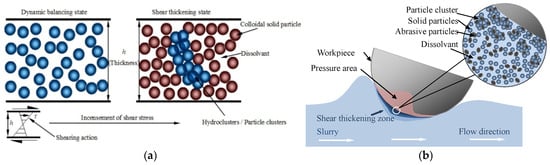
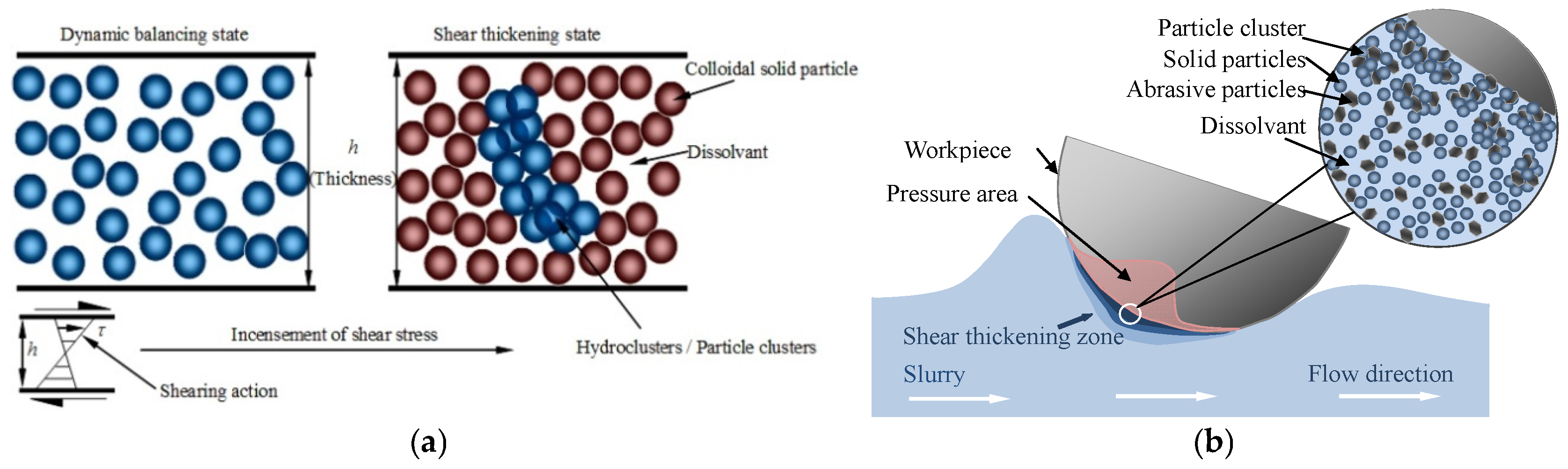
Shear-thickening fluid (STF) is a class of non-Newtonian fluids that exhibit a pronounced increase in shear viscosity under elevated shear rates [33]. The underlying mechanism responsible for shear thickening is generally associated with the formation of hydrogen-bonded clusters within the fluid (Figure 1a) [34]. The theory of FRP is demonstrated in Figure 1b [21]. As the slurry moves relative to the workpiece, the area touching the workpiece undergoes a shear force that surpasses a defined threshold, resulting in a shear-thickening effect. The uniform distribution of solid particles within the slurry encapsulates the abrasives, leading to the formation of particle clusters. Therefore, the viscosity of the slurry in the contact zone rises dramatically, exhibiting solid-like properties instantaneously. This enhancement facilitates improved control over the abrasives, effectively creating a flexible “fixed abrasive tool” on the workpiece surface. This mechanism enables efficient and adaptable processing of workpiece materials through the micro-cutting action of the abrasives, thereby significantly improving both MRR and the quality of the surface finish.
Figure 1.
FRP mechanism: (a) shear-thickening phenomenon; (b) FRP process.
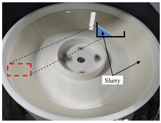
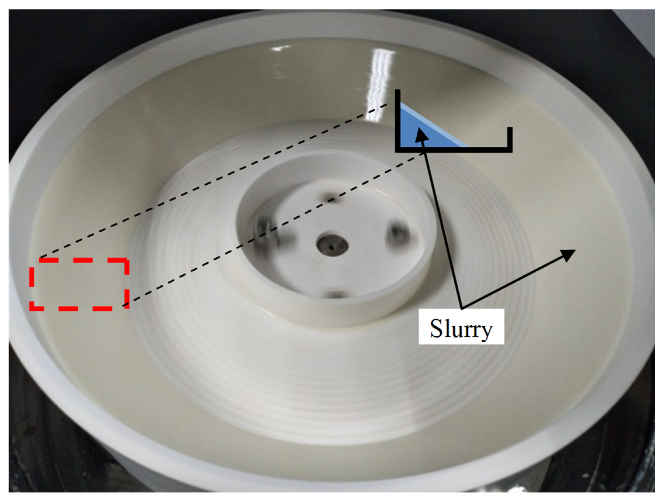
As previously discussed, the amplitude of the shear-thickening phenomenon is contingent upon the comparative speed of motion, and the rheological properties of the slurry present challenges in terms of regulation. Within a specific scope, an enhanced shear-thickening response requires an increased velocity. Figure 2 presents the effects of centrifugal force and non-uniform distribution of abrasives resulting from elevated processing rates, as well as the inadequate formation of a desirable shear-thickening phenomenon at low operational velocities, which remain unresolved. Therefore, the active management of shear-thickening intensity (i.e., minimizing the reliance of the viscosity increase on the shear rate) is emerging as a significant concern for FRP applications.
Figure 2.
Centrifugal force-induced variation in slurry distribution.
2.2. Theory of VFRP
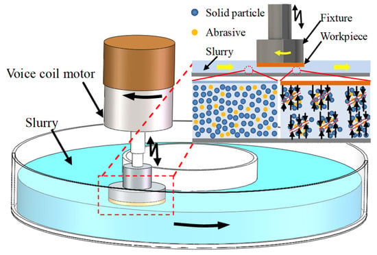
The mechanism of VFRP can be seen in Figure 3. In this process, a non-Newtonian power-law medium serves as the carrier fluid, with abrasive particles incorporated to formulate a polishing suspension. During machining, the slurry is subjected to vibrational excitation, inducing a comparative phase shift between the suspended particles. The localized elevation in shear rate triggers a dynamic rheological response within the polishing region. With increasing vibration intensity, the enhanced relative movement of solid particles promotes slurry thickening, resulting in a substantial increase in viscosity. This rheological transition strengthens the interaction between the polishing medium and abrasive particles, thereby improving the stability and retention capability of the abrasive phase. Owing to its enhanced rheological characteristics, the slurry can form a dynamic “fixed abrasive tool” that maintains close contact with the workpiece surface and facilitates material removal through controlled abrasive micro-cutting. By adjusting the vibration amplitude and frequency, the shear-thickening response of the slurry can be effectively regulated, enabling improved polishing performance under relatively low polishing speeds. The improved abrasive retention capability and intensified shear interaction at the workpiece interface contribute to enhanced material removal efficiency. In addition, VFRP effectively addresses the inherent limitations of conventional FRP, such as slurry loss and unstable distribution under high-speed polishing conditions. Consequently, VFRP enables a more stable and controllable material removal process, highlighting its potential for advanced ultra-precision surface polishing applications.
Figure 3.
Schematic of the VFRP process.
3. Shear Mechanism of Slurry and Simulation Analysis
3.1. Modeling Conditions
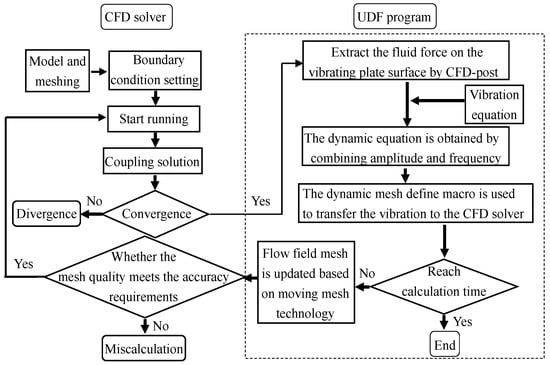
To examine the mechanical characteristics of the slurry under dynamic conditions, modeling conditions were established in accordance with the type of vibration depicted in the illustrative diagram. First, the vibrating platform was modeled as a perfectly rigid surface material. Second, the dispersed phases within the FRP slurry were assumed to be evenly distributed. Furthermore, the operational ambient temperature was maintained at 25 °C. Utilizing a computational fluid dynamics (CFD) tool within ANSYS Fluent 14.5, a force simulation was conducted to assess the effects of the vibrating platform on various slurries. The procedural diagram illustrating the simulation process can be seen in Figure 4.
Figure 4.
Flowchart of the simulation process for slurry surface pressure analysis.
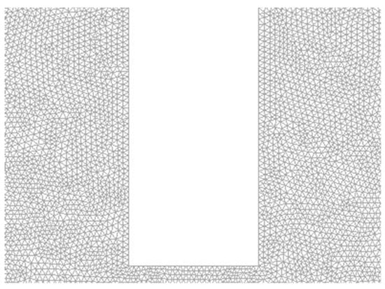
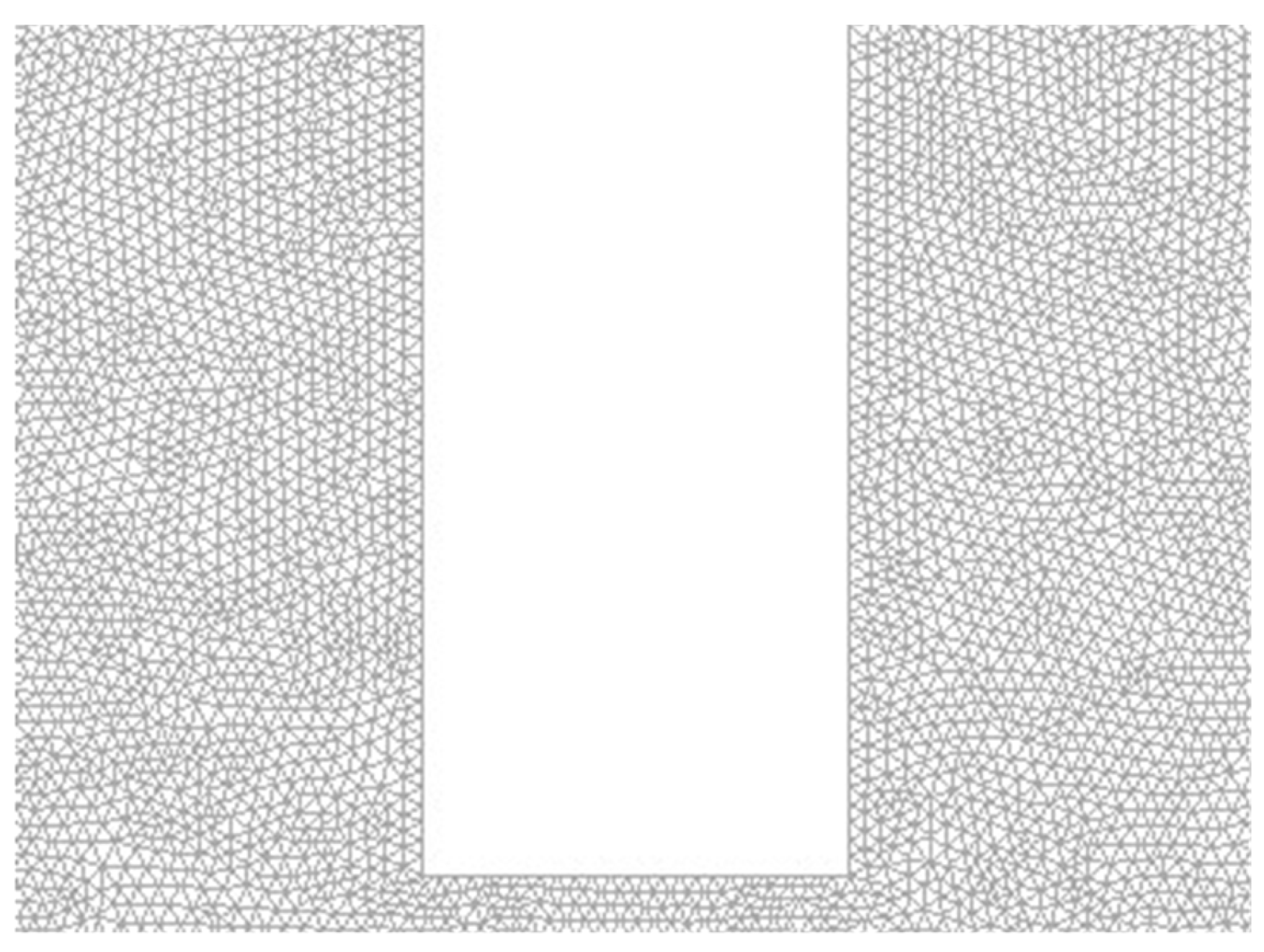
The computational model was constructed and discretized using ANSYS, as shown in Figure 5. The fluid domain was meshed through the ANSYS grid generation module to ensure sufficient numerical accuracy and stability. A triangular mesh was generated, with the maximum element area limited to 1 mm2. The minimum element area was set to 0.7 mm2 to prevent negative or invalid cell volumes during mesh deformation. Mesh distortion caused by vibration was mitigated through local mesh refinement and redistribution. Compared with the refined mesh configuration, in which the maximum and minimum element areas were reduced to 0.7 mm2 and 0.49 mm2, respectively, the relative deviation in peak pressure between the two meshes was less than 5%. Considering the balance between computational accuracy and cost, the former set of mesh parameters was adopted for subsequent simulations. The inlet of the fluid domain was set as the velocity-inlet boundary, and the outlet was defined as the pressure-outlet boundary. The outer boundaries of the fluid domain were treated as stationary walls. Numerical simulations were performed using ANSYS Fluent, where user-defined functions were developed to characterize the kinematic behavior of the vibrating plate. The plate was considered a rigid body undergoing prescribed motion, and its surface was defined as a moving wall boundary. The no-slip boundary condition was imposed on all walls, and standard wall functions were utilized. The simulation time step was selected as 1.5 ms. Since the Reynolds number of the vibration-induced flow field is much lower than 2300, the laminar flow model was adopted for the simulation, with a flow viscosity index (K) of 4 × 10⁻⁴ and a flow behavior index (n) of 2.7, values determined through systematic rheological analysis of the prepared slurry.
Figure 5.
Model with meshing for slurry pressure simulation.
3.2. Simulation Results
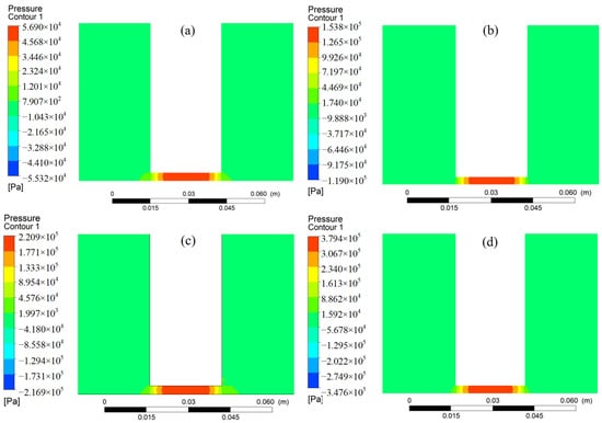
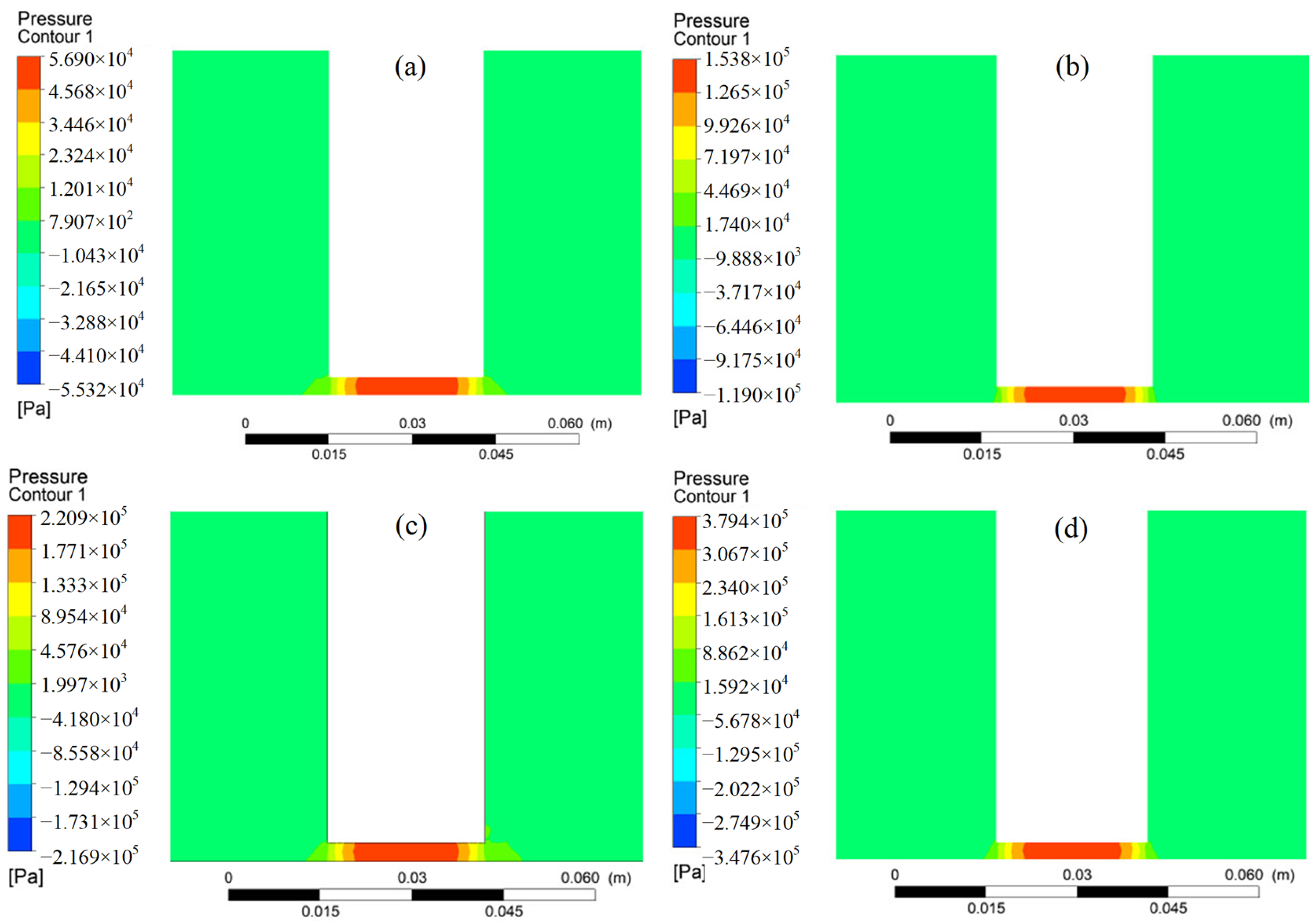
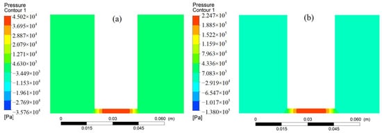
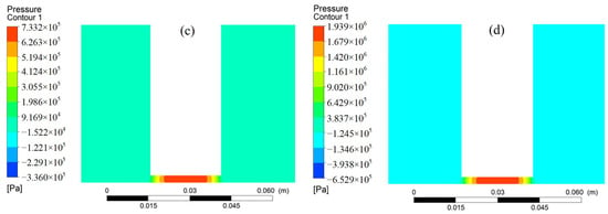
Figure 6 presents the simulated force responses of the vibrating plate under different vibration frequencies while maintaining a constant amplitude of 0.3 mm. The corresponding peak pressures at 60, 80, 100, and 120 Hz were determined to be 56.9, 153.8, 220.9, and 379.4 kPa, respectively. Under constant vibration amplitude, the maximum force exerted on the vibrating plate surface exhibits a continuous increase with increasing vibration frequency. Furthermore, the peak shear rate generated by slurry vibration increases proportionally with vibration frequency. The elevated shear rate strengthens the shear-thickening response of the slurry, resulting in increased viscosity and subsequently higher pressure on the vibrating plate.
Figure 6.
Simulated pressure distributions on the vibrating plate under various vibration frequencies: (a) 60 Hz; (b) 80 Hz; (c) 100 Hz; (d) 120 Hz.
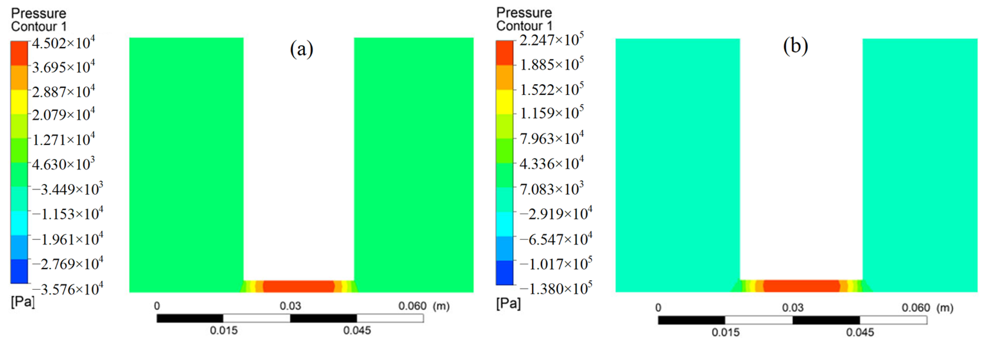
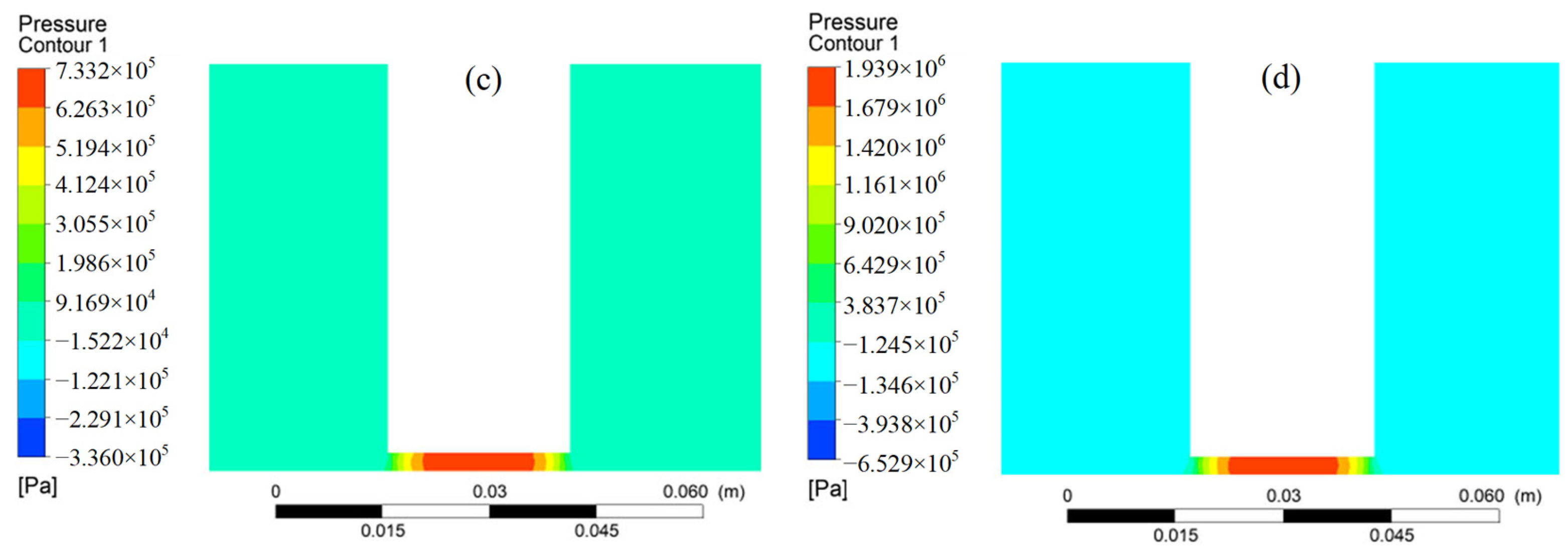
Figure 7 presents the simulated pressure distributions on the vibrating plate for various vibration amplitudes while maintaining a constant vibration frequency of 100 Hz. The peak pressures obtained under vibration amplitudes of 0.15, 0.25, 0.35 and 0.45 mm reached 45.0, 224.7, 773.2 and 1939.0 kPa, respectively. Under a constant vibration frequency condition, the peak pressure distributed over the plate surface increases steadily with the growth of amplitude. Furthermore, the peak shear rate caused by slurry vibration exhibits a positive correlation with vibration amplitude. The increase in shear rate strengthens the shear-thickening behavior of the slurry, thereby enhancing its viscosity and increasing the pressure applied to the vibrating plate.
Figure 7.
Analysis of pressure spread on vibrating surface with various amplitudes: (a) 0.15 mm; (b) 0.25 mm; (c) 0.35 mm; (d) 0.45 mm.
4. Study and Analysis
4.1. Evaluation of Slurry-Induced Pressure on the Workpiece Surface Under Vibrational Excitation
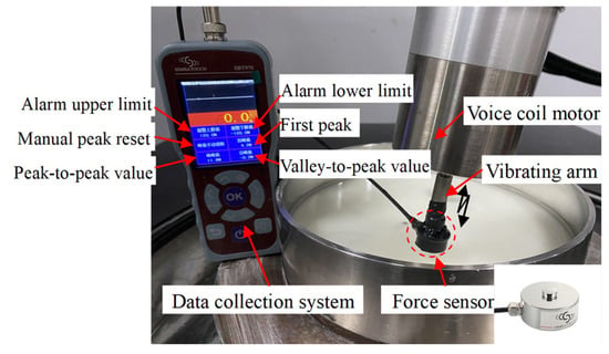
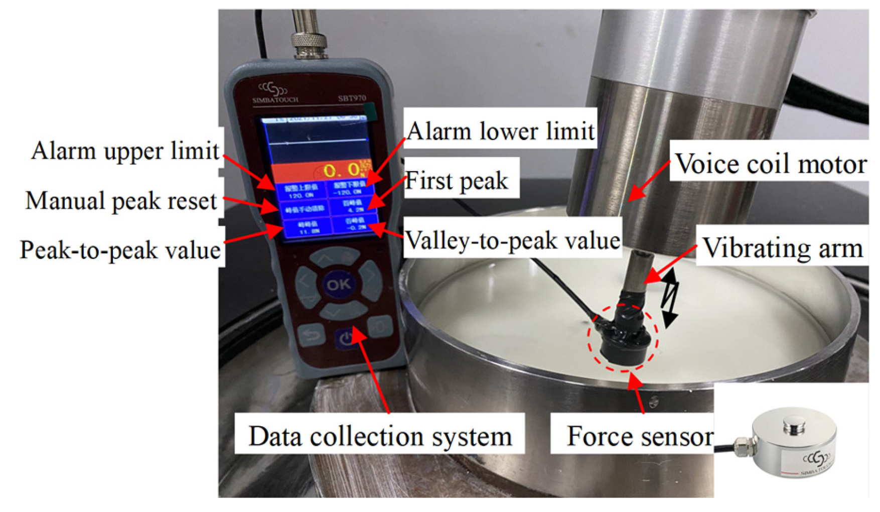
To explore the changes in contact force applied by the slurry on the workpiece in the course of the vibration activity, a load measurement setup was established (Figure 8). The VFRP slurry was placed inside the polishing basin. A voice coil motor was attached to the turning shaft, and the management program produced a vibration pattern with adjustable amplitude and frequency. The vibrating panel creates a dynamic impact on the slurry, causing a phase shift among the grains within the dynamic slurry, which in turn produces a flow gradient and triggers a flow behavior alteration. This interaction leads to the formation of a force chain among the solid particles, thereby enhancing the inter-particle forces and increasing the slurry viscosity. As relative movement occurs between the slurry and the vibrating plate, the slurry applies a distinct force on the vibrating plate. A precision force sensor (Simbatouch, Guangzhou, China) was used to measure the force response generated during vibration. The sensor exhibits a natural frequency ranging from 2800 to 3500 Hz and a maximum sampling frequency of 400 Hz. Prior to measurement, the system was allowed to stabilize for 30 min. The sensor was calibrated by first correcting the zero offset under no-load conditions and then performing gain calibration using standard weights at 60% and 80% of the full-scale capacity. The calibration accuracy was subsequently verified by applying standard weights with different loads. During data acquisition, a low-intensity median digital filter was applied to reduce measurement noise. The sensor featured a sensing area of 1 cm2 with an accuracy of 0.1 N. The force sensor was securely installed at the top of the vibration rod, allowing real-time monitoring and data acquisition of the slurry-induced pressure acting on the vibrating plate throughout each vibration cycle.
Figure 8.
Experimental setup for measuring vibration-assisted slurry force.
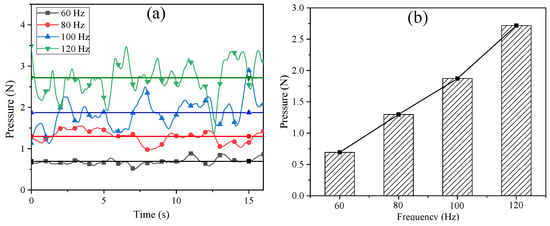
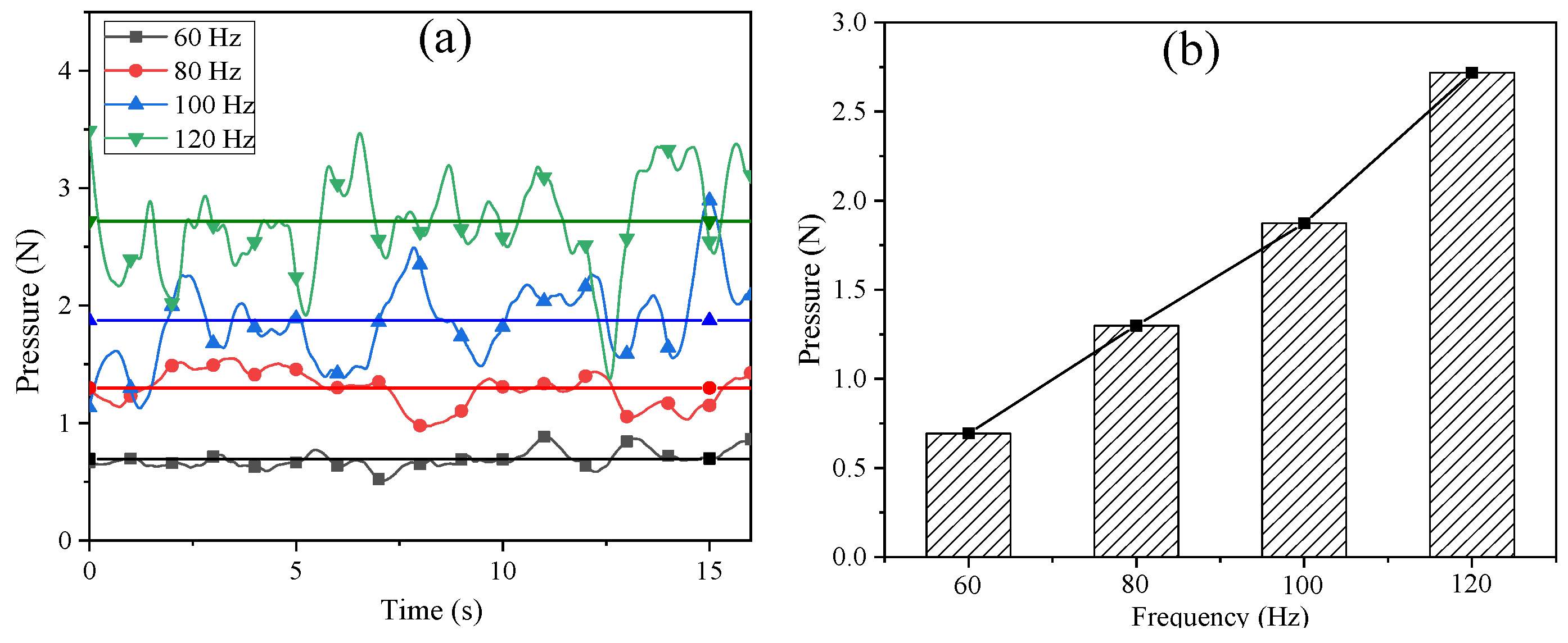
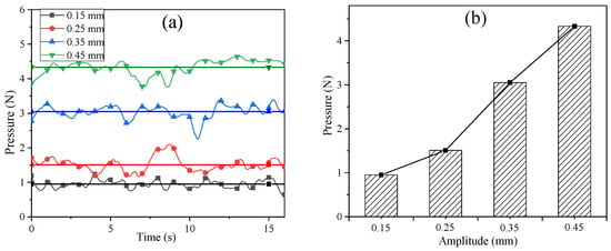
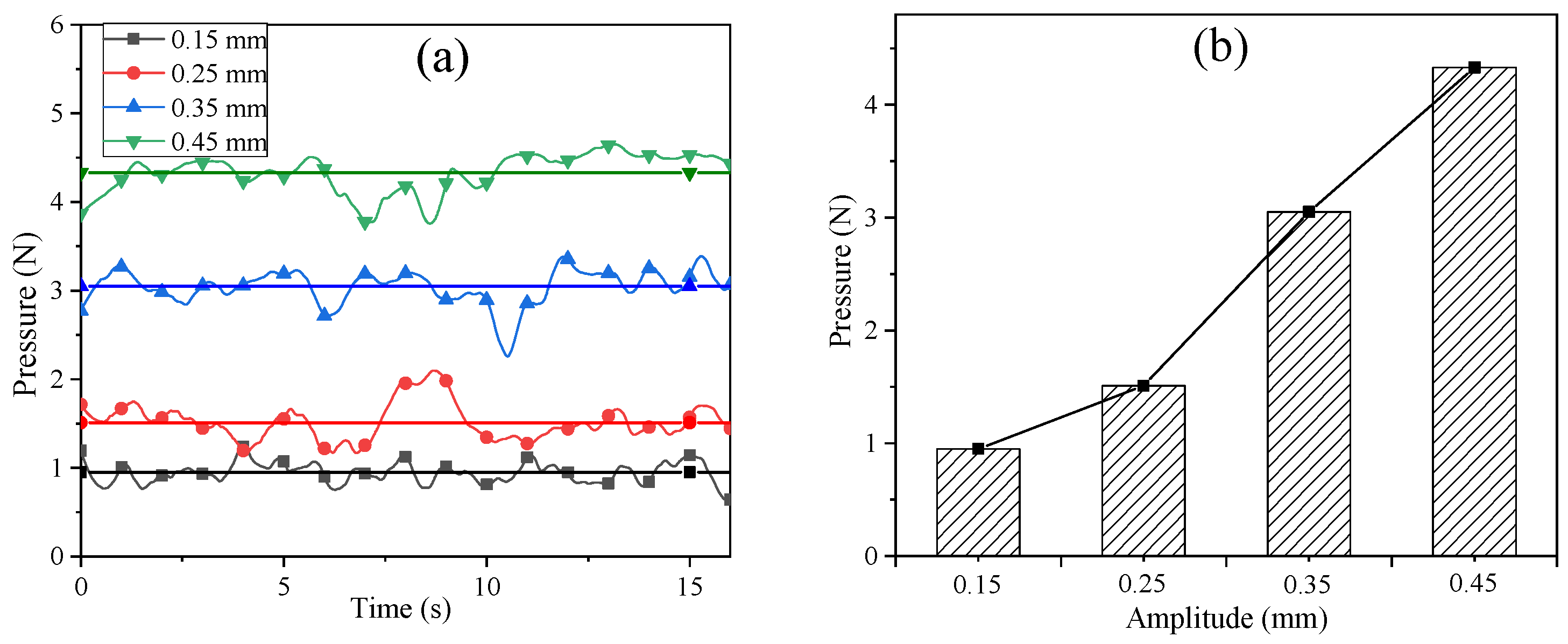
With the vibration amplitude fixed at 0.3 mm and the VFRP slurry subjected to different vibration frequencies, the corresponding forces acting on the vibrating surface are presented in Figure 9. Figure 10 illustrates the force response exerted by the VFRP slurry on the vibrating surface at a vibration frequency of 100 Hz, where the solid line indicates the average force trend. At a constant vibration frequency, both the average and peak forces acting on the vibrating plate surface increase progressively with increasing vibration amplitude. This behavior can be attributed to the coupling effect among shear rate, vibration amplitude, and frequency. The induced shear rate intensifies as the vibration amplitude and frequency increase, leading to enhanced slurry viscosity and consequently a higher force response on the vibrating surface.
Figure 9.
Measured force on workpiece surface at various vibration frequencies: (a) Instantaneous force distribution; (b) Comparison of average force.
Figure 10.
Measured force on workpiece surface at different amplitudes: (a) Instantaneous force distribution; (b) Comparison of average force.
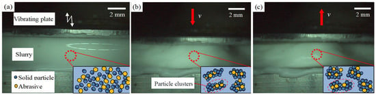
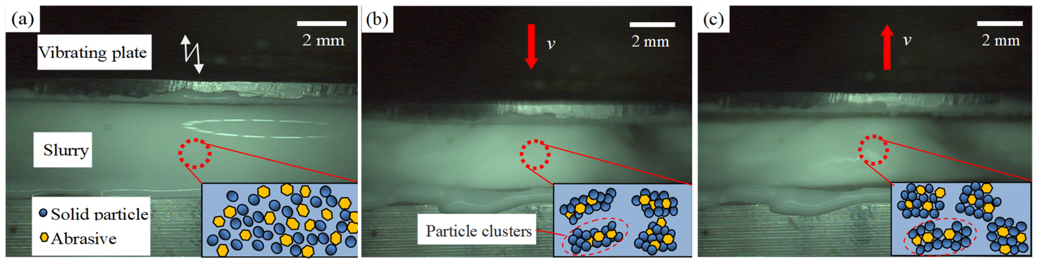
A vibrating plate was used to excite the slurry, and its surface morphological changes under vibration were monitored using a high-speed microscope (Keyence VW-9000, Osaka, Japan). Figure 11 illustrates the time-dependent evolution of the polishing slurry morphology at a vibration frequency of 60 Hz. In the absence of vibration, the slurry appears as a liquid, exhibiting a water mirror reflection (Figure 11a). Figure 11b depicts the slurry morphology at the maximum displacement of the vibrating plate, showing the emergence of banded structures and cavities. This surface morphological evolution is mainly associated with the relative displacement of particles under dynamic vibration, which induces non-uniform shear fields and activates the shear-thickening response of the slurry. The resulting increase in viscosity promotes a transition from a fluid-predominant state to a solid-resembling structure. Figure 11c illustrates the slurry morphology during the reverse motion of the vibrating plate. Because the applied vibration frequency exceeds the critical frequency required for the destruction of particle clusters, the shear-thickened structure remains stable.
Figure 11.
Surface morphological evolution of the slurry at a frequency of 60 Hz: (a) static state; (b) maximum displacement of the vibrating plate; (c) reverse motion of the vibrating plate.
Combining the simulated surface pressure analysis, experimental force measurements, and visualization of slurry morphological evolution under vibration, the slurry is demonstrated to experience a liquid-like to solid-like transition during the VFRP process. Increasing vibration intensity and frequency enhances the peak contact force exerted by the slurry on the workpiece surface. These periodic force variations play a critical role in determining polishing behavior and material removal efficiency. Consequently, a comprehensive analysis of the effects of vibration parameters on polishing performance is necessary.
4.2. Polishing Experiment
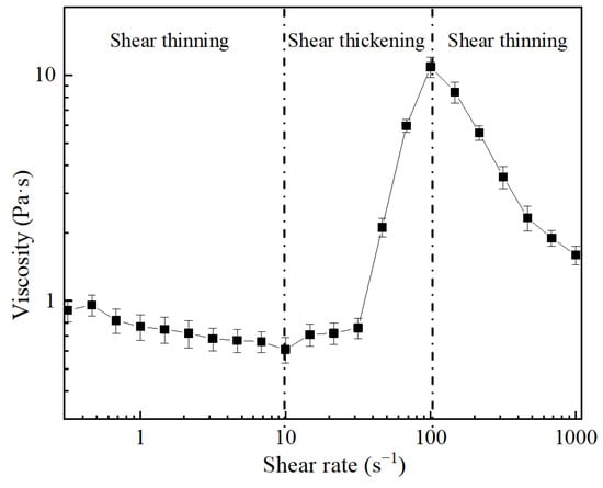
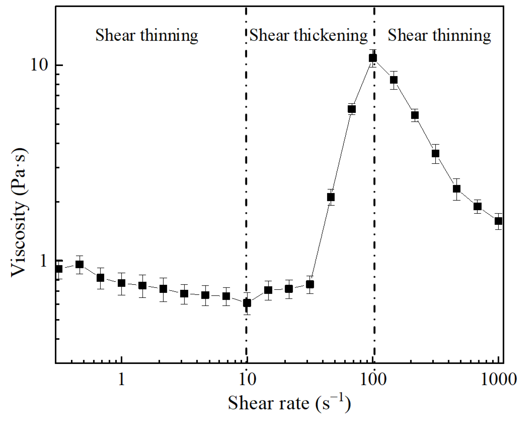
The VFRP slurry was prepared by dispersing 44% hydroxyl polymer, 30% SiO2 abrasive sol, and 1% glycerol dispersant in 25% purified water. The abrasive sol had a pH of 10 and contained 40 wt% abrasives with a mean particle size of 80 nm. The rheological characteristics of the slurry were evaluated utilizing a stress-controlled rotational rheometer (MCR 302, Anton Paar, Graz, Austria). Rheological measurements were conducted using cone-plate geometry with a diameter of 25 mm and a cone angle of 2°, and the gap distance was maintained at 0.103 mm. The temperature was maintained at 25 °C by a Peltier-based thermal regulation system. A single batch of polishing slurry was prepared, and three samples were taken from the same batch for rheological testing to reduce measurement error. Figure 12 presents the viscosity variation in the VFRP slurry containing 12 wt% abrasive particles as a function of shear rate. The slurry exhibited a three-stage rheological response. Initially, as the shear rate increased, the slurry viscosity gradually decreased, corresponding to a shear-thinning behavior. Upon reaching a critical shear rate, the slurry underwent a rapid viscosity increase associated with shear-thickening behavior. At higher shear rates, the viscosity decreased again, indicating a transition back to a shear-thinning regime.
Figure 12.
Rheological curves of polishing slurry.
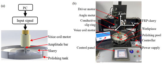
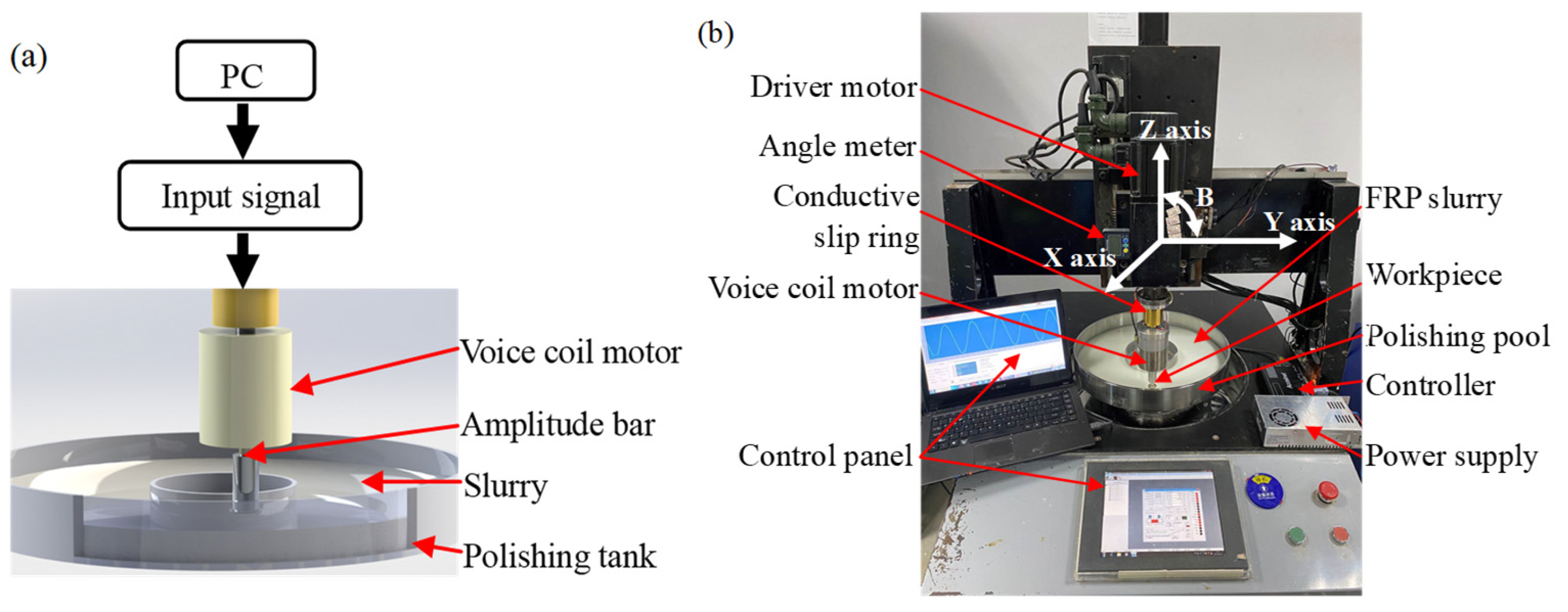
Figure 13 shows the experimental setup of the VFRP system. A linear actuator motor was mounted on the spinning shaft via a conductive rotary slip ring. The workpiece is secured to a spinning axle using a fixture, while the abrasive slurry within the processing chamber facilitates relative movement with the workpiece. Axial vibration with a designated amplitude and frequency is applied to the workpiece by the voice coil motor during the polishing refinement process. This vibration induces effective relative movement between the slurry and the workpiece while simultaneously generating a rheological effect within the slurry that results in a substantial rise in viscosity, thereby enhancing the holding strength on the abrasive particles. Stainless-steel sheets with a 25 mm diameter were utilized as the workpiece to evaluate the machining performance.
Figure 13.
Diagram of VFRP procedure and testing setup: (a) VFRP; (b) testing apparatus.
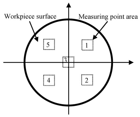
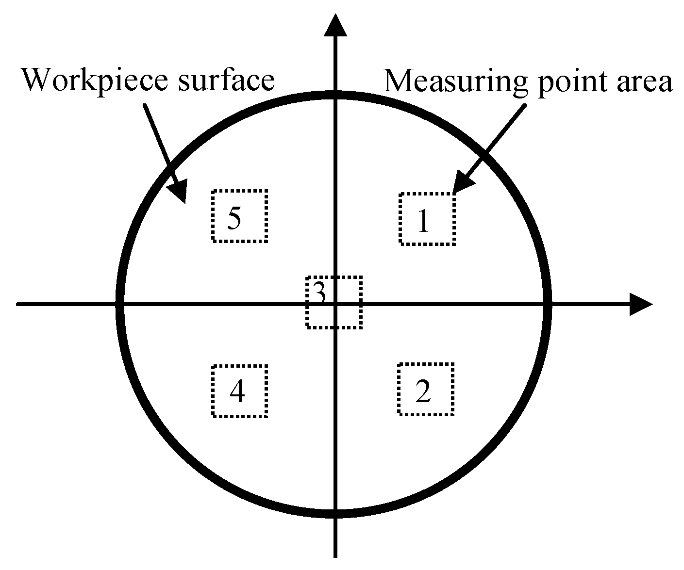
Table 1 details the testing parameters for VFRP, and the polishing time was fixed at 10 min. Surface roughness (Sa) at multiple positions was measured utilizing an optical interferometer (Super View W1, Chotest Technology Inc., Shenzhen, China). As shown in Figure 14, the surface roughness was measured at five randomly selected regions on each workpiece surface, and the average Sa value was calculated. The MRR was then determined using Equation (1). The mass of each workpiece before and after polishing was measured using a high-precision analytical balance (MSA225S-CE, Sartorius Lab Instruments GmbH & Co. KG, Göttingen, Germany) with a measurement resolution of 1 × 10⁻⁵ g. For each sample, three measurements were performed, and the average value was used to calculate the removed material mass (Δm).
where Δm denotes the material loss (g) calculated from the difference between the initial and final masses of the workpiece; ρ denotes the density of the workpiece (g/cm3); S represents the processed surface area (cm2); and t indicates the processing duration (min).
Table 1.
VFRP refinement test setup.
Figure 14.
Diagram depicting locations for a 316 stainless-steel workpiece.
4.2.1. Effect of Vibration Frequency
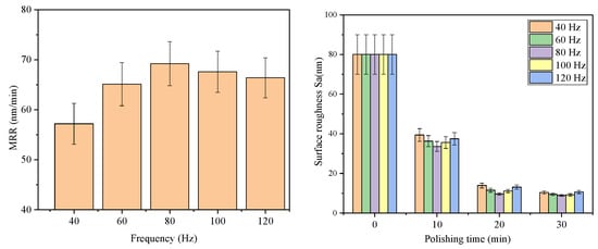
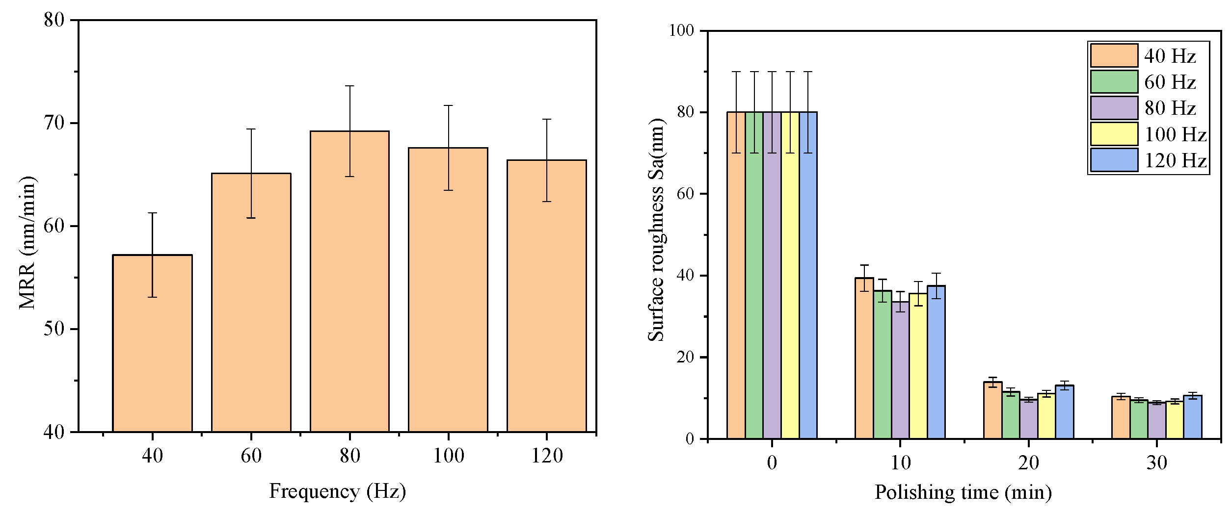
Figure 15 illustrates the variations in MRR and Sa under various vibration frequencies, with the amplitude fixed at 0.45 mm and the slurry velocity at 40 rpm. An initial rise in vibration frequency leads to an enhancement of both MRR and the rate of decrease in Sa, followed by a subsequent decline. This behavior is closely associated with the coupling between vibration frequency and shear rate. The increased vibration frequency intensifies the shear rate within the processing zone, thus promoting the shear-thickening response and increasing the slurry viscosity, shear force, and pressure applied to the workpiece surface. Therefore, maintaining a constant amplitude while increasing vibration frequency can lead to an improvement in MRR and a more rapid reduction in Sa. However, a continued rise in vibration frequency beyond 100 Hz results in a decline in MRR. The observed decline is primarily associated with the vibration-induced alteration of the shear-thinning behavior of the slurry. This rheological change weakens the slurry’s ability to remove fine surface asperities, resulting in an increase in surface roughness Sa.
Figure 15.
Effect of vibration frequency on MRR and Sa.
4.2.2. Effect of Vibration Amplitude
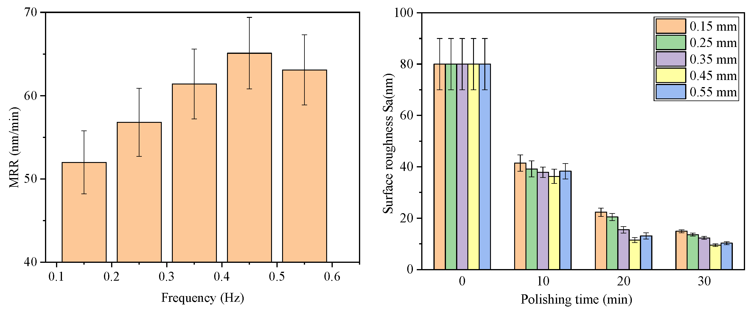
Figure 16 illustrates the influence of vibration amplitude on MRR and Sa under fixed processing conditions (polishing speed: 40 rpm; vibration frequency: 60 Hz). As the vibration amplitude increased, the MRR and the improvement in surface roughness initially increased due to the enhanced shear rate and abrasive retention capability of the slurry but subsequently decreased at higher amplitudes. Figure 12 illustrates the rheological characteristics of the VFRP slurry. As the shear rate increases beyond a critical value, the slurry viscosity rises rapidly, demonstrating a distinct shear-thickening response. The viscosity decreases again with a further increase in shear rate, indicating a subsequent shear-thinning regime. At a fixed vibration frequency, increasing the vibration amplitude intensifies the shear rate in the polishing zone, which strengthens the shear-thickening effect and enhances both slurry viscosity and interfacial shear stress. As a result, moderate amplitude enhancement facilitates abrasive retention and material removal, leading to an increased MRR and reduced Sa. However, excessive vibration amplitude weakens polishing stability, resulting in a reduction in MRR and a rise in Sa. The shear rate is governed by the coupled effects of vibration amplitude and frequency, showing a positive dependence on vibration intensity. Specifically, when the vibration frequency remains constant, an increase in vibration amplitude enhances the shear rate generated within the slurry. However, when the amplitude exceeds a specific value (0.5 mm), the shear rate enters the flow-thinning zone, resulting in a reduction in the shear stress applied by the slurry on the exterior. This reduction weakens the slurry’s ability to eliminate microconvex peaks on the material exterior, thereby causing a rise in Sa.
Figure 16.
Impact of vibration amplitude on MRR and Sa.
4.2.3. Effect of VFRP on Workpiece Surface Morphology
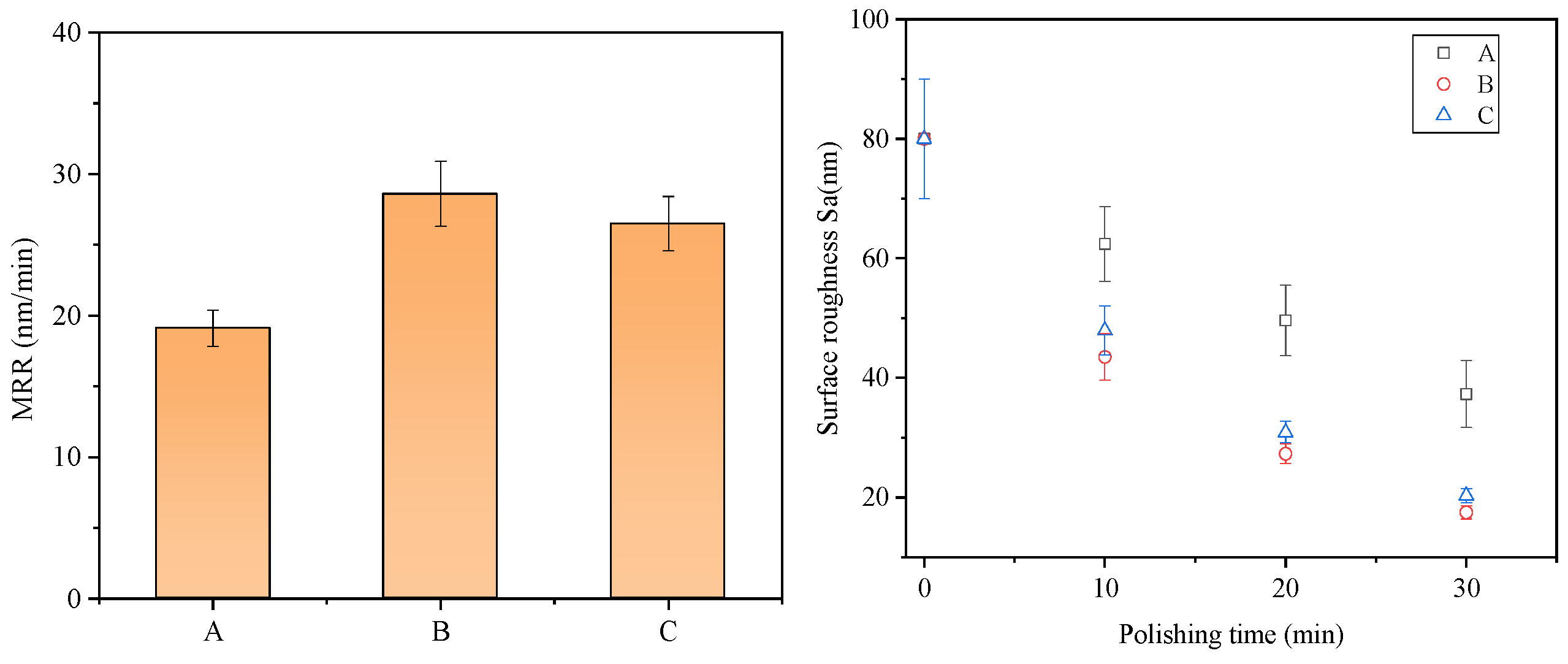
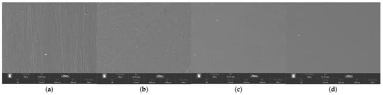
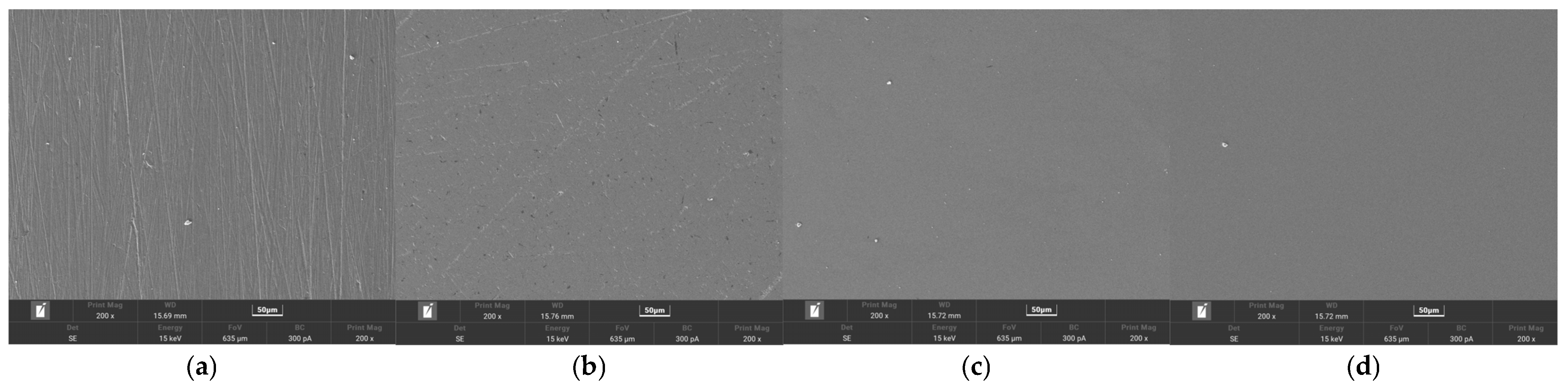
The connection between Sa and MRR shows that reduced Sa or elevated MRR, achieved within the same polishing duration, corresponds to increased processing efficiency. The experimental results obtained at a polishing speed of 20 rpm, with and without vibration, are depicted in Figure 17. Group A served as the reference group without vibration excitation. Group B was processed under a vibration frequency of 40 Hz and an amplitude of 0.45 mm, while Group C was subjected to a higher frequency of 100 Hz and a lower amplitude of 0.15 mm. Scanning electron microscopy (SEM, TESCAN ORSAY HOLDING, a.s., Brno, Czech Republic) images depicting the workpiece surface before and following 30 min of polishing are presented in Figure 18. After 30 min of polishing, the Sa value of the workpiece in Group A was reduced from 80 nm to 37.3 nm. Nevertheless, surface defects persisted on the workpiece surface, resulting in a modest MRR of 19.1 nm/min. Under low polishing speeds, the shear-induced thickening response of the slurry was insufficient to generate sufficient interfacial shear force, thereby limiting material removal efficiency. Thus, the marks on the material exterior persisted following 30 min of polishing in Group A, leading to heightened texture levels. With the application of appropriate vibration amplitude and frequency, the MRR was significantly enhanced, enabling the effective removal of microscopic protrusions on the material surface after 30 min of polishing. Compared with Group A, VFRP significantly reduced surface roughness, with final Sa values of 17.5 nm for Group B and 20.3 nm for Group C. The shear-thickening effect becomes pronounced when the slurry is exposed to vibration, resulting in an increase in apparent viscosity during the polishing operation, which in turn enhances the shear force applied by the slurry on the material exterior. Consequently, the MRR values of Groups B and C reached 28.6 nm/min and 26.5 nm/min, respectively, both of which were higher than that of Group A.
Figure 17.
MRR and Sa with and without vibration-assisted polishing.
Figure 18.
SEM images of workpiece surface: (a) prior to polishing; (b) Group A; (c) Group B; (d) Group C.
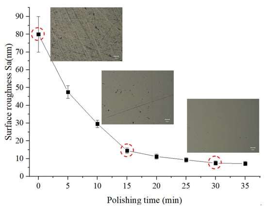
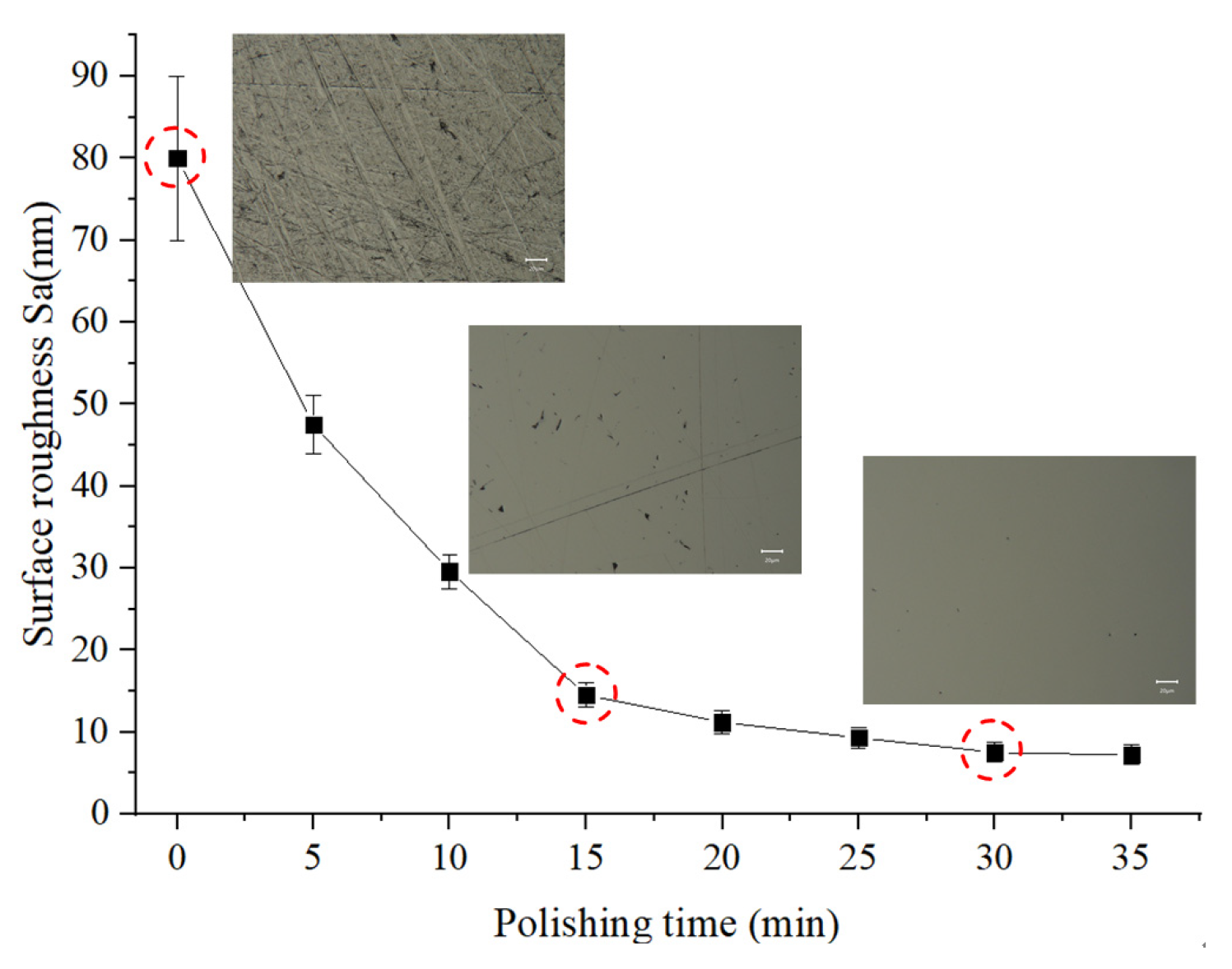
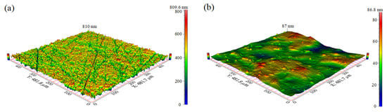
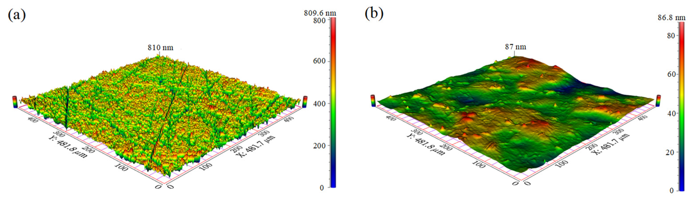
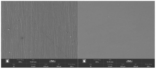
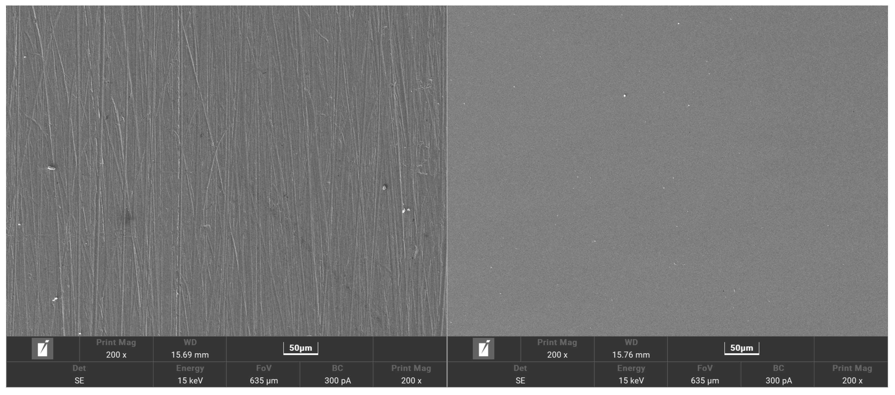
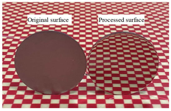
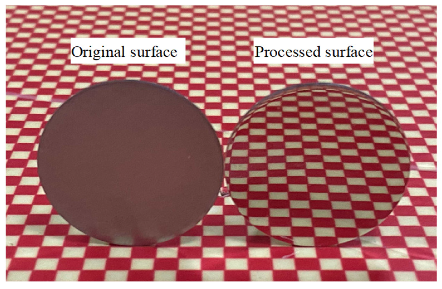
Following the investigation into the effects of vibration parameters on MRR and Sa, polishing experiments were conducted under the optimized processing conditions, namely a polishing speed of 40 rpm, a vibration amplitude of 0.35 mm, and a vibration frequency of 80 Hz. Figure 19 illustrates the time-dependent evolution of surface roughness and surface morphology of 316 stainless steel during polishing. The Sa decreased from 80 nm to 7.1 nm after 30 min of processing, demonstrating the high-efficiency polishing capability of the VFRP process. The corresponding three-dimensional surface profiles of the original and processed surfaces are displayed in Figure 20, while the microscopic surface appearances are shown in Figure 21. The macroscopic surface morphologies before and after polishing are shown in Figure 22. The initial machining-induced scratches were substantially eliminated, and a uniform reflective surface was obtained. Under these optimized conditions, the MRR was 68.1 nm/min.
Figure 19.
Time-dependent evolution of surface roughness (Sa) during the VFRP process.
Figure 20.
3D surface topography of the workpiece: (a) original; (b) processed.
Figure 21.
SEM images of workpiece surface morphology before and after polishing.
Figure 22.
Comparison of the surface morphology of 316 stainless-steel specimens before and after VFRP.
5. Conclusions
The developed VFRP technique effectively enhances polishing performance and surface integrity by controlling slurry rheological characteristics through vibrational excitation. The main conclusions obtained from the numerical simulations and experiments are summarized below:
Both numerical simulations and experimental analyses demonstrate that the contact pressure exerted by the vibration plate on the workpiece increases proportionally with vibration amplitude and frequency. Visualization of slurry morphology under vibration confirmed a liquid-like to solid-like transition induced by shear-thickening behavior, resulting in enhanced abrasive retention and improved polishing performance.
Within an optimal vibration range, increasing the amplitude and frequency promotes shear-rate enhancement, resulting in increased slurry viscosity and stronger interfacial interactions with the workpiece, which improves material removal efficiency. Beyond this range, excessive vibration parameters trigger shear-thinning behavior, weakening abrasive retention and leading to a decline in polishing performance.
At the optimized parameters (40 rpm polishing speed, 0.35 mm amplitude, and 80 Hz frequency), the VFRP process reduced the surface roughness (Sa) of 316 stainless steel from 80 nm to 7.1 nm after 30 min of polishing. The corresponding MRR reached 68.1 nm/min, and machining-induced scratches were substantially eliminated, yielding a highly smooth and reflective surface.
Author Contributions
Conceptualization, Q.S., B.L. and J.Y.; methodology, Q.S., L.G. and P.Z.; validation, Q.S. and J.W.; formal analysis, Q.S. and J.W.; investigation, Q.S., X.L. and D.Z.; resources, P.Z., X.L. and D.Z.; writing—original draft, Q.S., B.L. and J.Y.; writing—review and editing, Q.S., B.L. and J.Y.; visualization, Q.S., L.G. and X.L.; supervision, B.L. and P.Z.; funding acquisition, B.L., Q.S. and P.Z. All authors have read and agreed to the published version of the manuscript.
Funding
This work was co-supported by the National Natural Science Foundation of China (Grant No. U24A20124, 52505528, 51775508), the Natural Science Foundation of Zhejiang Province (Grant No. LMS25E050010), and the Taizhou Science and Technology Plan Project of China (Grant No. 25gya10, 24gya07).
Data Availability Statement
The original contributions presented in this study are included in the article. Further inquiries can be directed to the corresponding author.
Acknowledgments
During preparation of this manuscript, the authors used OpenAI ChatGPT 5.5 for language polishing. The authors reviewed and edited all output and take full responsibility for the content of this publication. Thank you for the support from the Open Fund of Zhejiang University of Technology.
Conflicts of Interest
Xiaofeng Lin was employed by Fangzheng Valve Group Co., Ltd., Wenzhou 325000, China. The remaining authors declare that the research was conducted in the absence of any commercial or financial relationships that could be construed as a potential conflict of interest.
Abbreviations
The following abbreviations are used in this manuscript:
| VFRP | Vibration-assisted force rheological polishing |
| MRR | Material removal rate |
| STP | Shear-thickening polishing |
| CMP | Chemical mechanical polishing |
| EEM | Elastic emission machining |
| MRF | Magnetorheological finishing |
| FRP | Force rheological polishing |
References
- Grinchuk, P.S.; Abuhimd, H.M.; Kiyashko, M.V.; Solovei, D.V.; Akulich, A.V.; Stepkin, M.O.; Lapitskaya, V.A.; Kuznetsova, T.A.; Danilova-Tretiak, S.M.; Evseeva, L.E. Advanced reaction-bonded SiC ceramics for space mirror blanks. J. Manuf. Process. 2024, 113, 275–290. [Google Scholar] [CrossRef] [Scilit]
- Liau, L.C.K.; Liau, K.M. Effect of slurry flow rate and down-force on material removal and defect performance during tungsten CMP. Microelectron. Reliab. 2024, 149, 115682. [Google Scholar]
- Olmo, R.D.; Revilla, R.I.; Debuisson, F.; Baert, K.; Van Hooreweder, B.; Rieux, A.D.; De Graeve, I.; Santos-Coquillat, A. Synergistic effects of etching and electropolishing on additively manufactured Ti-6Al-4V scaffolds for biomedical implants. Addit. Manuf. 2026, 116, 105083. [Google Scholar] [CrossRef] [Scilit]
- Li, J.; Hu, H.; Qiao, G.; Qi, E.; Bai, Y.; Li, F.; Liu, Z.; Li, L.; Yang, Z.; Zhang, X. Damage-free and ultra-smooth chemical mechanical polishing of calcium fluoride crystal surfaces. Precis. Eng. 2025, 94, 725–735. [Google Scholar] [CrossRef] [Scilit]
- Liu, D.; Yan, R.; Chen, T. Material removal model of ultrasonic elliptical vibration-assisted chemical mechanical polishing for hard and brittle materials. Int. J. Adv. Manuf. Technol. 2017, 92, 81–99. [Google Scholar] [CrossRef] [Scilit]
- Bennett, J.; Shaffer, J.J.; Shibano, Y.; Namba, Y. Float polishing of optical materials. Appl. Opt. 1987, 26, 696–703. [Google Scholar] [CrossRef] [Scilit]
- Yu, H.; Wen, D.; Qian, P.; Kong, F.; Yuan, Q. Effect of polishing roller structures on polished surface waviness in linear hydrodynamic polishing process. Int. J. Adv. Manuf. Technol. 2025, 138, 939–952. [Google Scholar] [CrossRef] [Scilit]
- Ma, W.; Li, J.; Zhang, X.; Ren, M.; Hou, X. Manufacture of ultra-smooth surface with low damage by elastic emission machining. J. Mater. Process. Technol. 2025, 338, 118780. [Google Scholar] [CrossRef] [Scilit]
- Zhou, X.; Wang, F.; Zhang, X.; Deng, H. Electrochemical polishing of microfluidic moulds made of tungsten using a bi-layer electrolyte. J. Mater. Process. Technol. 2021, 292, 117055. [Google Scholar] [CrossRef] [Scilit]
- Ji, J.; Khan, M.; Zhan, Z.; Yi, R.; Deng, H. Electrochemical Polishing of Tungsten: An Investigation of Critical Spatial Frequency and Ultimate Roughness. Int. J. Adv. Manuf. Technol. 2022, 120, 5755–5762. [Google Scholar]
- Wang, Y.; Yin, S.; Hu, T. Ultra-precision finishing of optical mold by magnetorheological polishing using a cylindrical permanent magnet. Int. J. Adv. Manuf. Technol. 2018, 97, 3583–3594. [Google Scholar] [CrossRef] [Scilit]
- Ghosh, G.; Sidpara, A.; Bandyopadhyay, P.P. Theoretical analysis of magnetorheological finishing of HVOF sprayed WC-Co coating. Int. J. Mech. Sci. 2021, 207, 106629. [Google Scholar] [CrossRef] [Scilit]
- Jiang, M.; Komanduri, R. Application of Taguchi method for optimization of finishing conditions in magnetic float polishing (MFP). Wear 1997, 213, 59–71. [Google Scholar] [CrossRef] [Scilit]
- Wang, L.; Sun, Y.; Xiao, Z.; Yang, F.; Kang, S.; Liu, Y.; Zuo, D. A Review of Magnetic Abrasive Finishing for the Internal Surfaces of Metal Additive Manufactured Parts. J. Manuf. Mater. Process. 2024, 8, 261. [Google Scholar] [CrossRef] [Scilit]
- Li, L.; Li, X.; Cheng, Q.; Li, R.; Deng, W.; Luo, X.; Zhang, F.; Xue, D.; Zhang, X. Optimized strategy to restrain the mid-spatial-frequency surface error in computer-controlled optical surfacing. Results Phys. 2020, 19, 103356. [Google Scholar] [CrossRef] [Scilit]
- Zhao, Y.; Liu, X.; Fang, Y.; Cao, C. Ultra-Precision Processing of Conductive Materials via Electrorheological Fluid-Assisted Polishing. Adv. Eng. Mater. 2020, 23, 2001109. [Google Scholar] [CrossRef] [Scilit]
- Pan, R.; Zhao, W.; Zhong, B.; Chen, D.; Wang, Z.; Zha, C.; Fan, J. Evaluation of removal characteristics of bonnet polishing tool using polishing forces collected online. J. Manuf. Process. 2019, 47, 393–401. [Google Scholar] [CrossRef] [Scilit]
- Wang, C.; Zhang, Z.; Cheung, C.; Luo, W.; Loh, Y.; Lu, Y.; Kong, L.; Wang, S. Maskless fluid jet polishing of optical structured surfaces. Precis. Eng. 2022, 73, 270–283. [Google Scholar] [CrossRef] [Scilit]
- Liu, Q.; Dong, Z.; Chen, Z.; Shen, Y.; Li, Q.; An, P. Experimental investigation of flow-focusing-assisted magnetorheological jet polishing. Appl. Opt. 2022, 61, 6366–6373. [Google Scholar] [CrossRef] [Scilit]
- Wang, T.; Cheng, H.; Zhang, W.; Yang, H.; Wu, W. Restraint of path effect on optical surface in magnetorheological jet polishing. Appl. Opt. 2016, 55, 935–942. [Google Scholar] [CrossRef] [Scilit]
- Li, M.; Lyu, B.; Yuan, J.; Dong, C.; Dai, W. Shear-thickening polishing method. Int. J. Mach. Tools Manuf. 2015, 94, 88–99. [Google Scholar] [CrossRef] [Scilit]
- Shen, M.; Wei, M.; Wu, L.; Hong, B.; Ye, J.; Chen, H.; Yuan, J.; Lyu, B.; Wang, C.; Deng, H.; et al. Microwave plasma modification assisted shear thickening polishing of single crystal silicon carbide. Precis. Eng. 2025, 94, 13–25. [Google Scholar] [CrossRef] [Scilit]
- Tian, Y.; Qian, C.; Yuan, X.; Arora, K.; Wu, G.; Chen, Z.; Wang, Q. Investigation on sedimentation, magnetization, and polishing characteristics for magnetorheological shear thickening polishing fluids. J. Magn. Magn. Mater. 2025, 630, 173476. [Google Scholar] [CrossRef] [Scilit]
- Zhao, J.; Wang, W.; Qiu, X.; Wang, Z.; Fan, C. Material removal profile model simulations and experiments on the non contact shear thickening polishing of K9 glass. J. Manuf. Process. 2025, 134, 435–451. [Google Scholar] [CrossRef] [Scilit]
- Zhao, J.; Bi, S.; Li, W.; Luo, Y.; Liu, X.; Zeng, X.; Wang, Z. Material removal mechanism and surface roughness prediction–optimization for near atomic scale surface generation via shear thickening polishing. Precis. Eng. 2026, 102, 618–632. [Google Scholar] [CrossRef] [Scilit]
- Li, M.; Karpuschewski, B.; Riemer, O.; Li, Y.; Dong, T. New graphene-enhanced shear-thickening polishing slurry. CIRP Ann.-Manuf. Technol. 2026, 75, 425–429. [Google Scholar] [CrossRef] [Scilit]
- Ke, M.; Zhou, Y.; Chen, Y.; Wang, F.; Li, D.; Shao, L.; Wang, J.; Lyu, B. Drilling Performance of cemented carbide microdrill cutting edges prepared by shear thickening polishing. Int. J. Precis. Eng. Manuf.-Green Technol. 2026, 1–23. [Google Scholar] [CrossRef] [Scilit]
- Ke, M.; Dai, Y.; Wang, J.; Li, H.; Wu, X.; Lyu, B. Experimental study on the cutting edge preparation of cemented carbide inserts by shear thickening polishing. Int. J. Adv. Manuf. Technol. 2025, 140, 763–776. [Google Scholar] [CrossRef] [Scilit]
- Nguyen, D.N.; Dao, T.P.; Prakash, C.; Singh, S.; Pramanik, A.; Krolczyk, G.; Pruncu, C.I. Machining parameter optimization in shear thickening polishing of gear surfaces. J. Mater. Res. Technol. 2020, 9, 5112–5126. [Google Scholar] [CrossRef] [Scilit]
- Yuan, J.; Wang, J.; Lyu, B.; Hang, W. Force rheological polishing technology. J. Mech. Eng. 2022, 58, 21–30. [Google Scholar] [CrossRef] [Scilit]
- Liu, M.; Wang, J.; He, H.; Yuan, J.; Lyu, B.; Chen, H.; Peng, G. Performance of flexible CeO2 composite abrasive in force rheological polishing of fused silica glass. J. Manuf. Process. 2024, 126, 175–184. [Google Scholar] [CrossRef] [Scilit]
- Liu, M.; Wang, J.; Liu, W.; Wu, H.; Yuan, J.; Lyu, B.; Peng, G.; Zhang, J. Force rheological polishing of polycrystalline magnesium aluminate spinel using agglomerated diamond abrasive. Ceram. Int. 2024, 50, 55275–55285. [Google Scholar] [CrossRef] [Scilit]
- Hassan, A.T.; Rangari, K.V.; Jeelani, S. Synthesis, processing and characterization of shear thickening fluid (STF) impregnated fabric composites. Mater. Sci. Eng. A 2010, 527, 2892–2899. [Google Scholar] [CrossRef] [Scilit]
- Wagner, N.J.; Brady, J.F. Shear thickening in colloidal dispersions. Phys. Today 2009, 62, 27–32. [Google Scholar] [CrossRef] [Scilit]

Disclaimer/Publisher’s Note: The statements, opinions and data contained in all publications are solely those of the individual author(s) and contributor(s) and not of MDPI and/or the editor(s). MDPI and/or the editor(s) disclaim responsibility for any injury to people or property resulting from any ideas, methods, instructions or products referred to in the content. |
© 2026 by the authors. Licensee MDPI, Basel, Switzerland. This article is an open access article distributed under the terms and conditions of the Creative Commons Attribution (CC BY) license.