


Abstract
To address the prevalent defects in industrially cast 8021 aluminum alloy for battery foil, including coarse iron-rich phases that sever the matrix and hard-to-remove micrometer-scale inclusions, alloys with different chemical compositions were manufactured on a 100-ton integrated industrial melting and holding production line. The regulatory principles and underlying mechanisms of Fe–Ce composite microalloying on solidification thermal behavior, melt purification efficiency, as-cast microstructure, mechanical properties, and corrosion resistance of the alloy were systematically investigated. The results show that when the mass fractions of Fe and Ce are 1.7% and 0.3%, respectively, the mean intercept length of the α-Al grains of the alloy is reduced by 29% compared with the reference alloy. The acicular iron-rich phases are modified into dispersively distributed short rod-like and granular particles, and the filtration removal efficiency of micro-inclusions in the melt is significantly improved. The ultimate tensile strength of the alloy reaches 94.0 MPa, and the elongation is increased to 44.2%. The corrosion current density in 3.5 wt.% NaCl solution is only 20% of that of the Ce-free reference alloy. Through multi-stage effects including melt purification, grain refinement and second-phase modification induced by joint Fe and Ce additions, the combined addition of Fe and Ce simultaneously improves the metallurgical quality and service performance of the alloy. This work provides theoretical support and engineering references for the stable industrial production of high-performance aluminum foil for lithium-ion battery packaging.
1. Introduction
With the rapid expansion of the new energy vehicle and energy storage industries, the market demand for lithium-ion batteries has maintained sustained growth. Soft-pack lithium-ion batteries have become one of the mainstream technical routes owing to their advantages of lightweight design, high energy density, and flexible forming geometry. Aluminum plastic film serves as the core packaging material of soft-pack batteries, among which AA 8021 aluminum foil acts as the intermediate barrier layer. It requires outstanding cold stamping formability, excellent resistance to electrolyte corrosion and an extremely low pinhole defect rate. Its metallurgical quality and microstructure homogeneity directly determine the packaging reliability and service life of lithium-ion cells [1,2,3]. Currently, the industrial demand for ultra-thin battery foil is continuously increasing. However, intrinsic defects in conventional as-cast AA 8021 ingots, such as coarse iron-rich intermetallics, inhomogeneous grains and molten slag inclusions, easily induce rolling strip breakage and excessive pinhole defects, which become critical bottlenecks restricting the large-scale production of high-performance battery foil [4,5].
AA 8021 is an Al–Fe series wrought aluminum alloy. Fe is its dominant alloying element, generating dispersion strengthening via Al–Fe intermetallic compounds and simultaneously suppressing recrystallization to control grain size. Nevertheless, under conventional industrial casting conditions, Fe tends to precipitate as coarse acicular Al3Fe phases. These hard and brittle phases severely break the continuity of the aluminum matrix, drastically deteriorating alloy plasticity and subsequent cold forming performance. Moreover, the potential difference between acicular iron-rich phases and the Al matrix triggers micro-galvanic corrosion, accelerating matrix dissolution and impairing the corrosion resistance of battery foil [5,6,7,8]. Therefore, regulating the morphology and distribution of iron-rich phases, refining matrix grains and reducing molten slag inclusions at the metallurgical source are core approaches to improve the comprehensive performance of AA 8021 battery foil.
Existing domestic and international studies on microstructure and property regulation of AA 8021 aluminum alloy mostly focus on optimizing post-processing technologies. Zhao et al. [4] systematically explored the combined effects of cold rolling and homogenization treatment on the microstructure and mechanical properties of twin-roll cast AA 8021 alloy, realizing fragmentation and uniform distribution of iron-rich phases by adjusting process parameters. Chen et al. [9,10] separately clarified the influences of annealing heating rate and homogenization regime on microstructure and texture evolution of AA 8021 foil stock, establishing the correlation between process parameters and microstructure evolution. Jin et al. [11] further revealed the regulation mechanism of grain size on mechanical and forming properties of AA 8021 foil. However, technological modification essentially serves as a post-treatment of the primary as-cast microstructure, and its optimization effect is inherently limited by the initial metallurgical quality of ingots. Microalloying that modifies as-cast microstructures from the source is recognized as a more fundamental technical strategy [12,13].
Rare earth microalloying technology has attracted extensive attention in the high-performance development of aluminum alloys due to its combined effects of grain refinement, second-phase modification and melt purification [14,15]. Cerium (Ce), the most abundant light rare earth element in the Earth’s crust and relatively low in cost, is among the most widely used rare earth modifiers for aluminum alloys. In a comprehensive review, Czerwinski [14] summarized the functional mechanisms of Ce in aluminum alloys, stating that Ce can act as heterogeneous nucleation sites by forming high-melting-point intermetallics to refine grains, and simultaneously combine with impurities including O, H and alkali metals in melts to form stable compounds, achieving deep melt purification. For Al–Fe alloy systems, Vončina et al. [16] investigated the influences of La and Ce addition on solidification processes of Al–Fe alloys via thermal analysis, verifying that rare earth elements alter the precipitation temperature and pathway of iron-rich phases. Qu et al. [17] analyzed the melt structure of Al–Fe–Ce alloys and the formation nature of strengthening phases from electronic theory, providing theoretical support for Ce alloying effects. Li et al. [18] further discovered that Ce promotes the transformation of acicular Al3Fe phases into granular and Chinese script-like morphologies, significantly improving the strength–toughness matching of Al–Fe alloys. For the AA 8021 alloy system, Mu et al. [19] preliminarily explored the grain refining efficiency of varying Ce contents. Sun et al. [12,13] studied the effects of Sr and Nd additions on the microstructure, mechanical properties and hot deformation behavior of AA 8021 alloys, confirming the positive regulatory effects of rare earth microalloying.
In terms of corrosion resistance regulation, previous research demonstrates that rare earth Ce improves the corrosion resistance of aluminum alloys by optimizing their microstructure. Zhou et al. [20] reported that Ce addition refines grains of Al–Ce alloys and facilitates the formation of continuous and dense passive films, enhancing corrosion resistance in 3.5 wt.% NaCl solution. Li et al. [21] conducted research on high-strength Al–Zn–Mg–Cu alloys, revealing that Ce reduces corrosion propagation rates by adjusting the size and distribution of second phases and weakening micro-galvanic corrosion. At present, most studies on the corrosion resistance of AA 8021 battery foil concentrate on surface conversion coating modification [1,2,3], while research on improving intrinsic corrosion resistance via alloy composition design remains limited. Nevertheless, primary metallurgical microstructures exert a decisive influence on the long-term corrosion service performance of battery foil.
Although existing studies have verified the positive effects of Ce on aluminum alloy microstructures and properties, critical knowledge gaps still exist for AA 8021 battery-foil alloys under practical industrial mass-production conditions. Most published studies concerning Ce modification of Al-Fe-based alloys have been conducted in laboratory-scale small crucible furnaces. Such laboratory conditions cannot reproduce the complex impurity background, melt holding time, and temperature field of 100-ton industrial melting lines, which greatly limits the transferability of laboratory findings to real-world production [19,22]. Our previous work [23] investigated the modification effect induced by single Ce addition on as-cast AA 8021 alloy, and clarified the links between second-phase evolution, mechanical performance and corrosion behavior. Nevertheless, that study did not consider the coupled influence of varied Fe content together with Ce addition, which is an essential factor for industrial AA 8021 alloy.
Three major research gaps can be summarized as follows. First, most relevant investigations are performed under laboratory conditions rather than in real industrial melting scenarios, which limits the engineering applicability of the findings. Second, existing studies on rare earth-modified AA 8021 alloys mostly focus on the modification effect of single rare earth elements; the bidirectional complementary regulation mechanism between Fe and Ce, as well as the coupling effects of inclusion purification and heterogeneous nucleation under complex industrial impurity backgrounds, have not been fully clarified. Third, the intrinsic mechanism through which Ce modification counteracts the microstructural defects induced by high Fe content and breaks the strength–ductility trade-off remains poorly understood, failing to provide direct theoretical guidance for industrial composition optimization.
Our previous laboratory-scale work (Ref. [23]) revealed the modification effect of single Ce addition at fixed Fe content for AA 8021 alloy under high-purity laboratory conditions. However, it does not reflect the real response of Ce modification under complex industrial impurity backgrounds and varying Fe contents. The present work focuses on 100-ton industrial melting-casting experiments, with extra attention to melt-filtration behavior and solidification thermal characteristics, which were not investigated in Ref. [23].
To address the above research gaps, this work fabricated three groups of AA 8021 aluminum alloy flat ingots with different Fe and Ce contents (S1: 1.5 wt.% Fe, Ce-free; S2: 1.5 wt.% Fe, 0.3 wt.% Ce; S3: 1.7 wt.% Fe, 0.3 wt.% Ce) on a 100-ton integrated industrial melting and holding line. Multiple characterization techniques, including simultaneous DSC–TGA thermal analysis, tubular filtration slag testing, metallographic and SEM microstructure observation, room-temperature tensile testing, and electrochemical measurement, were adopted to systematically study the influences of Fe–Ce composite modification on solidification thermal behavior, melt purification efficiency, as-cast microstructure, mechanical properties, and corrosion resistance of AA 8021 alloys. The micro-regulatory behaviors under combined Fe and Ce additions were revealed, and a well-performing composition matching scheme suitable for industrial production was identified within the present experimental range. This work not only verifies the modification effect of Ce under industrial production conditions, but also reveals the academic nature of Fe–Ce combined regulation and its multi-stage mechanism. This work focuses on the composition and microstructure optimization of industrial as-cast AA 8021 ingots. The melt purification and microstructural modification achieved in the as-cast state can improve subsequent thermo-mechanical processability and provide an important experimental basis for high-quality battery foil production.
2. Materials and Methods
2.1. Alloy Preparation
Three batches of AA 8021 aluminum alloy flat ingots were produced on a 100-ton integrated industrial melting and holding line, with designed compositions denoted as S1 (1.5 wt.% Fe, 0 wt.% Ce), S2 (1.5 wt.% Fe, 0.3 wt.% Ce) and S3 (1.7 wt.% Fe, 0.3 wt.% Ce). The target and measured chemical compositions are listed in Table 1. The Ce content of 0.3 wt.% was determined based on our previous laboratory-scale optimization work (Ref. [23]), in which 0.3 wt.% Ce was confirmed to provide optimal comprehensive modification efficiency for the AA 8021 alloy. This work aims to verify the engineering applicability of Ce modification under 100-ton industrial production conditions. Considering industrial cost control and process stability, the Ce content was fixed at 0.3 wt.% in Ce-containing alloys, and the combined regulatory effect of varying Fe content paired with Ce addition was emphatically investigated.
Table 1.
Main chemical compositions of three AA 8021 aluminum alloys (wt.%).
Raw materials consisted of industrial primary aluminum ingots, grade-1 clean 1060 aluminum scrap, and AlSi20, AlFe20, AlCe20 master alloys. The complete industrial melting and casting workflow is described as follows: In the batching stage, special measuring rods were used to measure the weight of residual molten aluminum in the furnace at multiple points, and spectral composition grading inspection was performed on aluminum scraps. Thin aluminum scraps, primary ingots, and large remelted ingots were weighed separately and loaded into charging hoppers, with the total single-furnace feeding amount strictly controlled below the rated 100-ton capacity. The furnace was preheated above 700 °C before layered charging: thin scraps were laid at the bottom, primary ingots were placed in the middle, and large bulk scraps were stacked on the upper layer, followed by liquid virgin aluminum. The furnace gas temperature was maintained at 1020–1050 °C for melting. Slag flux was added when the molten aluminum reached 710 °C, and mother liquid spectral samples were collected at 710–750 °C as the baseline for alloying calculation. The maximum melt temperature was kept below 765 °C throughout the process to suppress high-temperature element burnout.
Differentiated alloying was carried out at a constant melt temperature of 720–750 °C. For S1 alloy, Fe content was adjusted to 1.5 wt.% only via Al–Fe master alloy. For S2 alloy, Fe was calibrated to 1.5 wt.% first, and then Al–Ce rare earth master alloy was added to reach 0.3 wt.% Ce. For S3 alloy, Fe content was elevated to 1.7 wt.% before adding an identical amount of Al–Ce master alloy. Electromagnetic stirring was applied for no less than 30 min after each master alloy addition, and extended to 1 h when the total supplementary alloy mass exceeded 5 tons. After standing and re-testing to confirm qualified compositions, the melts proceeded to the refining procedure. Argon injection powder refining was performed for 15–20 min in the melting furnace, followed by pure argon purging for 5 min upon refining completion. Refined melts were transferred to a matched holding furnace with melt temperature maintained at 735–750 °C. After secondary purification via STAS equipment, slag skimming and standing, continuous casting was conducted to obtain three batches of AA 8021 flat ingots with differentiated compositions.
After demolding, all ingots were uniformly machined with a CNC milling machine (Shin Nippon Koki Co., Ltd., Sakai, Japan) to remove oxidation segregation layers at the head, tail, top, and bottom surfaces, eliminating surface slag, pores, and coarse surface intermetallics that would interfere with subsequent testing caused by heterogeneous surface casting microstructures. Milled ingot surfaces were smooth and free of machining scratches, and intact primary solidification microstructures at the ingot core were reserved for sampling, characterization, and performance testing. The actual chemical compositions of final ingots were verified by in-furnace OES rapid analysis during melting, followed by ICP-OES quantitative testing on core samples machined from the as-cast flat ingots.
2.2. Thermal Analysis
Simultaneous thermogravimetric analysis and differential scanning calorimetry (TGA–DSC) were conducted using a TA Instruments SDT Q600 thermal analyzer (New Castle, DE, USA) with the matching software V20.9 Build 20 to characterize phase transformation temperatures and thermal stability of the three alloy variants. Specimens with a mass of approximately 10 mg were placed in alumina crucibles and heated from room temperature to 700 °C at a heating rate of 10 °C/min.
2.3. Tubular Filtration Slag Testing
Slag samples were collected at the inlet and outlet of an industrial online tubular ceramic filter for Ce-free (S1) and Ce-containing (S2) alloy melts. Specimens were ground and polished prior to metallographic observation and SEM–energy-dispersive X-ray spectroscopy (EDS) analysis.
2.4. As-Cast Microstructure Characterization
An OLYMPUS DSX500 (Olympus, Tokyo, Japan) optical metallographic microscope equipped with an image acquisition and analysis system was used to observe macroscopic metallographic microstructures. Anodic oxidation coating was performed on specimens using a DC-stabilized power supply to acquire clear grain boundaries with distinct contrast for grain size measurement; the anodizing parameters are summarized in Table 2. After anodizing, specimens were wiped with anhydrous ethanol, dried, and then observed under the polarized light mode of the optical microscope. The mean intercept length of α-Al grains of the alloys was statistically calculated via the intercept method following GB/T 6394-2002 [24] using OLYCIA DSC software (Version 3.2). It should be noted that the intercept method directly yields the mean intercept length rather than the geometrical average grain diameter, and additional conversion factors are required to obtain the true average grain size. A ZEISS EVO18 scanning electron microscope (SEM) (Carl Zeiss Microscopy GmbH, Jena, Germany) coupled with an EDS detector was adopted to analyze the morphology and chemical composition of second-phase particles.
Table 2.
Anodic oxidation coating parameters for three AA 8021 aluminum alloys.
2.5. Room Temperature Mechanical Properties Testing
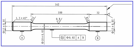
An MTS 810 universal material testing machine (MTS Systems Corporation, Eden Prairie, MN, USA) was used to conduct room-temperature tensile tests. Tensile specimens were machined according to GB/T 6397 [25] Metallic Materials—Tensile Test Specimens, with dimensions illustrated in Figure 1. Four replicate tensile bars were fabricated for each alloy group. The diameter of the cylindrical gauge section was measured six times (three positions along the length, two perpendicular directions at each position) with a micrometer, and the average value was adopted as the nominal diameter. The tensile strain rate was set to 1 mm/min. The full test process, data acquisition, processing, and recording were automatically completed by MTS proprietary software (Version 5.9E). Four replicate tensile strength and elongation datasets were measured for each sample, and the average values were taken as representative mechanical properties. SEM was utilized to observe fracture surfaces of tensile specimens and analyze fracture mechanisms.
Figure 1.
Schematic diagram of the room-temperature tensile specimen of AA 8021 aluminum alloy.
2.6. Electrochemical Corrosion Measurements
A CHI660E electrochemical workstation (Shanghai Chenhua Instrument Co., Ltd., Shanghai, China) equipped with a standard three-electrode system was employed to perform potentiodynamic polarization curve measurements and electrochemical impedance spectroscopy (EIS) tests. A platinum sheet served as the counter electrode, a saturated calomel electrode (SCE) as the reference electrode, and the alloy specimen as the working electrode. A Luton electrochemical specimen fixture was used to fix the working electrode, controlling the exposed testing area to 1 cm2. The corrosive medium was a 3.5 wt.% sodium chloride aqueous solution. Before testing, specimens were immersed in the NaCl solution for 30 min until the open-circuit potential stabilized. Parameters for potentiodynamic polarization tests: scanning rate = 1 mV/s, potential range = −0.2 V to 0.6 V vs. SCE. Parameters for EIS measurements: frequency range = 105–10−2 Hz, amplitude of sinusoidal excitation signal = 5 mV.
All measurements were performed at room temperature, with three repeated tests for each group to guarantee data reliability. Origin software (OriginPro 2022) was used to fit the Tafel regions of polarization curves to extract the corrosion potential and corrosion current density. ZSimpWin software (Version 3.20), combined with equivalent circuit models, was applied to fit EIS data and obtain characteristic electrochemical parameters, in order to analyze differences in corrosion resistance and corrosion kinetic behavior of different specimens.
3. Results and Discussion
3.1. Solidification Thermal Behavior and Thermal Stability of Alloys
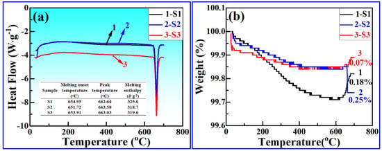
Figure 2 presents the DSC heat flow curves and TGA thermogravimetric curves of three Fe–Ce modified AA 8021 aluminum alloys. All three alloys exhibited a single broad endothermic peak corresponding to the eutectic melting of the α-Al matrix and iron-rich intermetallic phases, which conformed to the typical non-equilibrium solidification characteristics of Al–Fe-based alloys. For the Ce-free S1 alloy, the melting peak temperature was approximately 658 °C with a melting enthalpy of 392 J/g. When 0.3 wt.% Ce was added while maintaining Fe at 1.5 wt.% (S2), the melting peak temperature shifted ~5 °C to a higher value, and the melting enthalpy increased to 405 J/g. Further elevating the Fe content to 1.7 wt.% while maintaining a constant Ce content of 0.3 wt.% (S3) raised the melting peak temperature to 667 °C, broadened the half-height width of the endothermic peak, and widened the melting range by approximately 8 °C. The evolution of these phase transformation characteristics stemmed from the tendency of Ce to combine with Fe and Al to form high-melting-point ternary Al–Fe–Ce intermetallic compounds, which increased the overall melting characteristic temperature of the alloy. Meanwhile, the atomic bonding force within the melt and the stability of atomic clusters were strengthened, raising the heat required for melting and manifesting as an elevated melting enthalpy [16,17]. Higher Fe content significantly increased the volume fraction of iron-rich intermetallics. The coexistence of binary Al–Fe phases and ternary Al–Fe–Ce phases with divergent melting temperatures broadened the overall melting interval.
Figure 2.
Thermal analysis curves of three Fe–Ce modified AA 8021 aluminum alloys: (a) DSC heat flow curves; (b) TGA thermogravimetric curves.
In terms of high-temperature thermal stability, negligible mass variation was detected for all alloys from room temperature to 400 °C, which mainly originated from the desorption of adsorbed moisture or gas on the specimen surfaces and the formation of an extremely thin surface oxide film; no obvious differences were observed among groups. When the temperature exceeded 400 °C, the surface oxidation rate accelerated, oxygen atoms diffused inward into the matrix, and obvious mass loss occurred. At the test endpoint of 700 °C, the Ce-free S1 alloy achieved the highest total thermal weight loss of 0.25%. After adding 0.3 wt% Ce, the total weight loss of S2 decreased to 0.18%, while S3 with elevated Fe content only exhibited a weight loss of 0.07%. The high-temperature oxidation resistance gradually improved with the combined addition of Fe and Ce.
Ce improved thermal stability via two mechanisms: surface segregation, which forms a dense oxide film, and binding impurities, which block internal oxidation channels [14,18]. Meanwhile, the increased Fe content generated dispersed precipitates that pinned grain boundaries and hindered oxygen diffusion, producing favorable joint effects together with Ce. Fe–Ce composite microalloying effectively regulated the melting thermodynamics of AA 8021 aluminum alloy and markedly enhanced high-temperature thermal stability. The combination of 1.7 wt.% Fe and 0.3 wt.% Ce delivered the most prominent optimization effect, providing a thermodynamic foundation for subsequent melt purification and as-cast microstructure regulation.
3.2. Melt Purification and Slag Removal Behavior
Melt cleanliness represented a core index governing the metallurgical quality of as-cast AA 8021 battery foil ingots. Micrometer-scale oxide inclusions and impurity phases easily induce pinholes and strip breakage during subsequent rolling, while industrial ceramic filtration exhibits inherent limitations in intercepting submicron fine inclusions [14,22]. Rare earth Ce possesses strong chemical activity, which strengthens melt purification by modifying inclusion properties and promoting the agglomeration and growth of micro-inclusions. In this subsection, tubular filtration slag testing and multi-scale characterization were combined to analyze the evolution rules of slag in aluminum melts and the purification mechanism under Fe–Ce composite regulation.
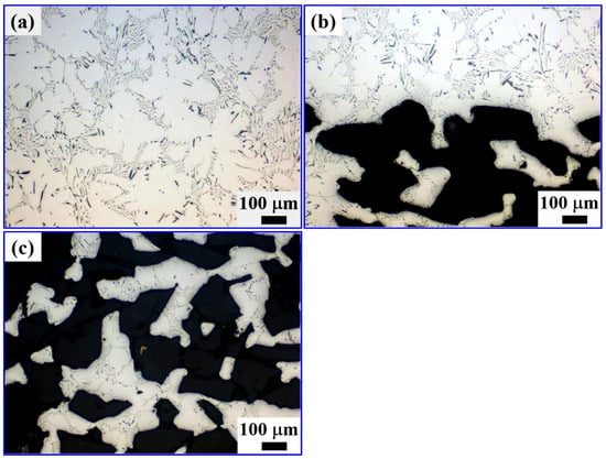
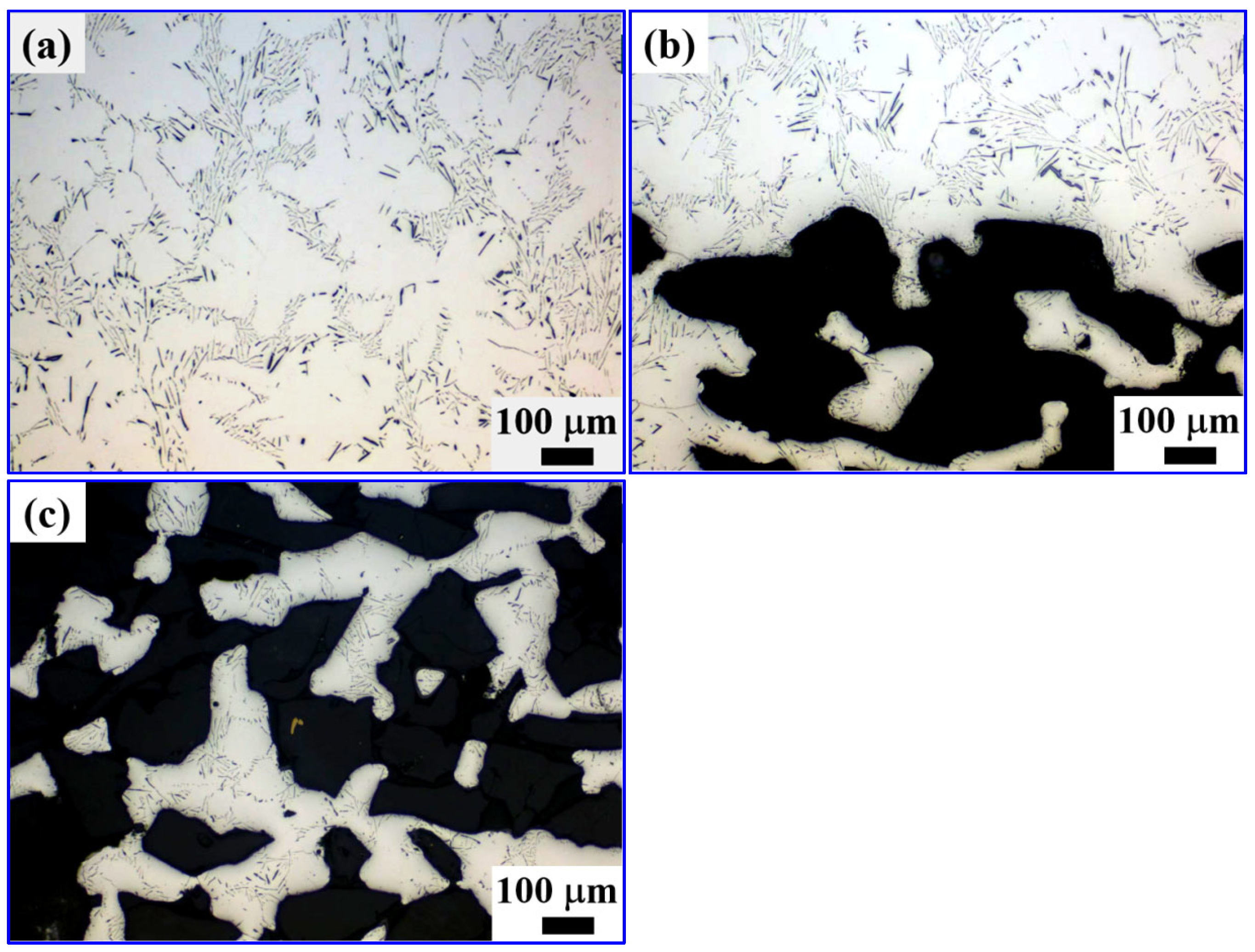
For the Ce-free S1 alloy melt, the metallographic morphologies of filtration slag specimens are displayed in Figure 3. Sparse fine particulate inclusions were distributed in the matrix region (Figure 3a). However, massive blocky black slag accumulated at the alloy-filter interface (Figure 3b) and inside filter pores (Figure 3c). This indicated that the traditional filtration system only effectively intercepted large primary oxide inclusions, which concentrated at the front end and internal pores of the filter. A large number of submicron dispersed oxide inclusions and alkali metal impurities pass through filter pores and remain in the matrix, acting as potential defect initiation sites during subsequent rolling. These residual sub-micron oxide inclusions and alkali metal impurities are inherent in industrial aluminum melts rather than being artificially prepared. They mainly originate from three pathways: raw material introduction, in situ oxidation during melting, and incomplete removal by conventional refining. Raw aluminum ingots and recycled scrap carry surface oxide films and trace electrolytic alkali metal residues; during high-temperature melting, surface oxide layers break into fine particles and disperse into the melt, while dissolved alkali metals remain in the liquid phase. Conventional refining and ceramic filtration can only eliminate large-sized inclusions above 10 μm, and most sub-micron fine impurities pass through filter pores and remain in the matrix as native defects.
Figure 3.
Metallographic morphologies of slag test specimens of Ce-free AA 8021 aluminum alloy: (a) alloy matrix region; (b) alloy–filter interface region; (c) filter medium region.
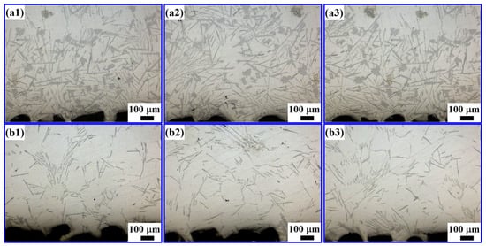
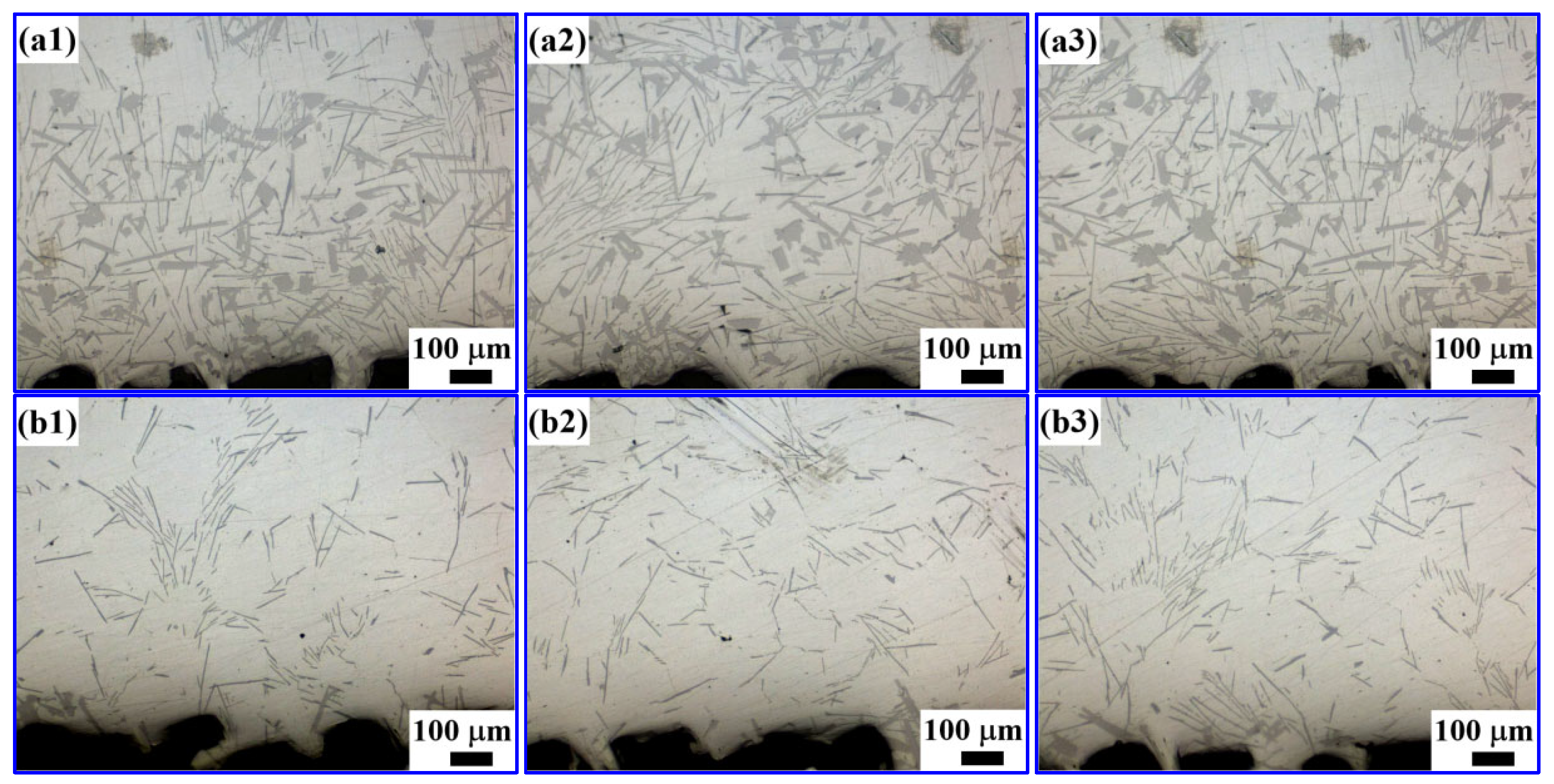
Figure 4 shows the metallographic morphologies of tubular filter slag specimens from the AA 8021 alloy with 0.3 wt.% Ce addition. As presented in Figure 4(a1–a3), abundant agglomerated composite slag with equivalent sizes much larger than those of native inclusions in the Ce-free system appeared at the filter inlet. The quantity of inclusions in the matrix at the filter outlet (Figure 4(b1–b3)) further decreased, and the melt cleanliness surpassed that of S1 without Ce. This phenomenon confirmed that Ce drove the collision, agglomeration, and coarsening of dispersed micro-inclusions in the melt to form larger composite slag, which could be more readily intercepted and removed by ceramic filters, drastically boosting the removal efficiency of micro-inclusions in industrial filtration processes.
Figure 4.
Metallographic morphologies of slag test specimens from a tubular filter for Ce-containing AA 8021 aluminum alloy: (a1–a3) filter inlet side; (b1–b3) filter outlet side.
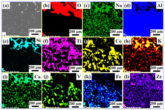
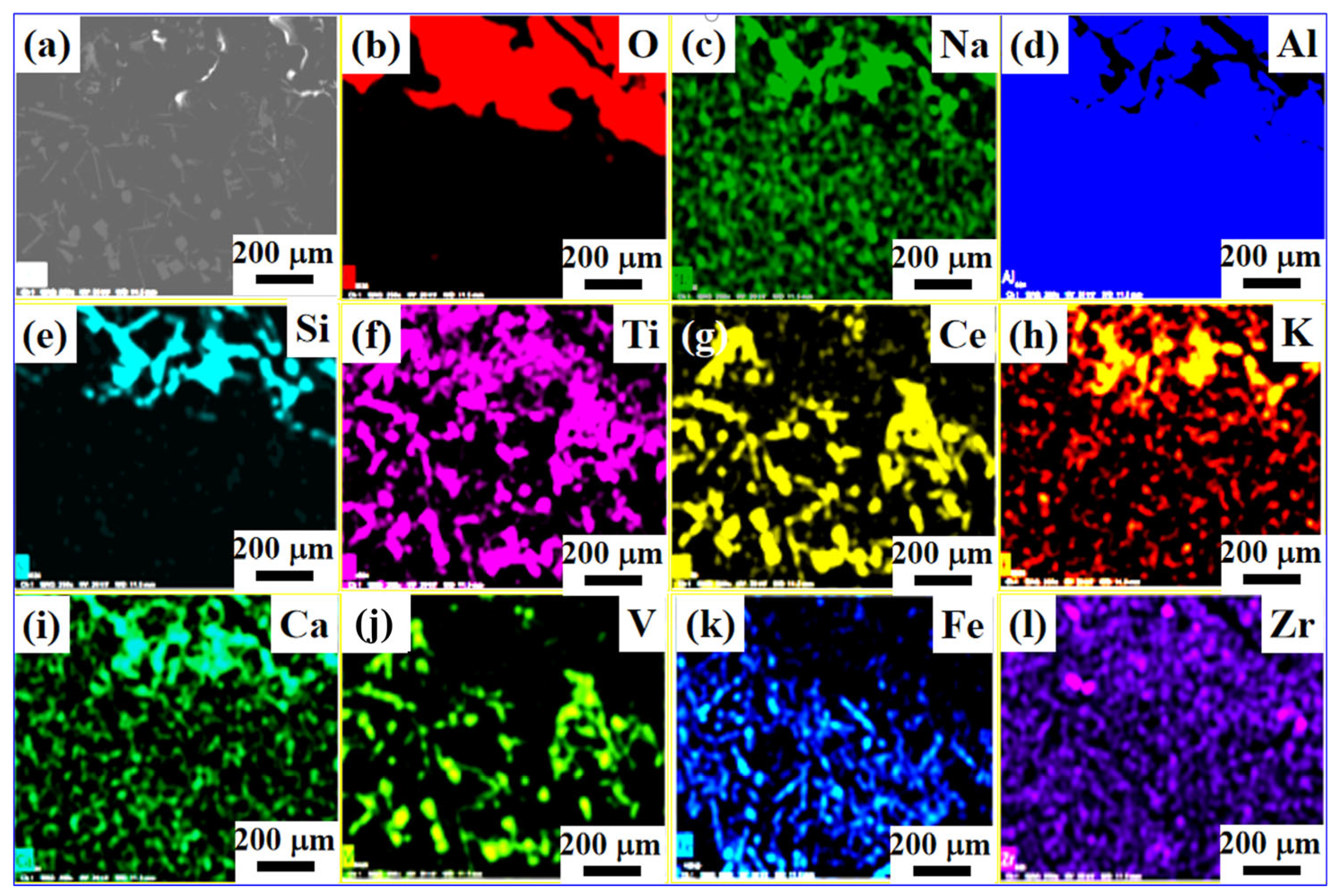
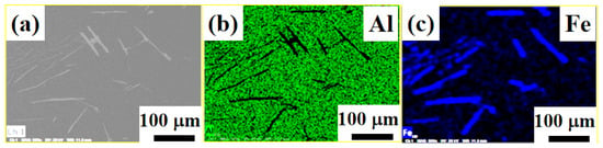
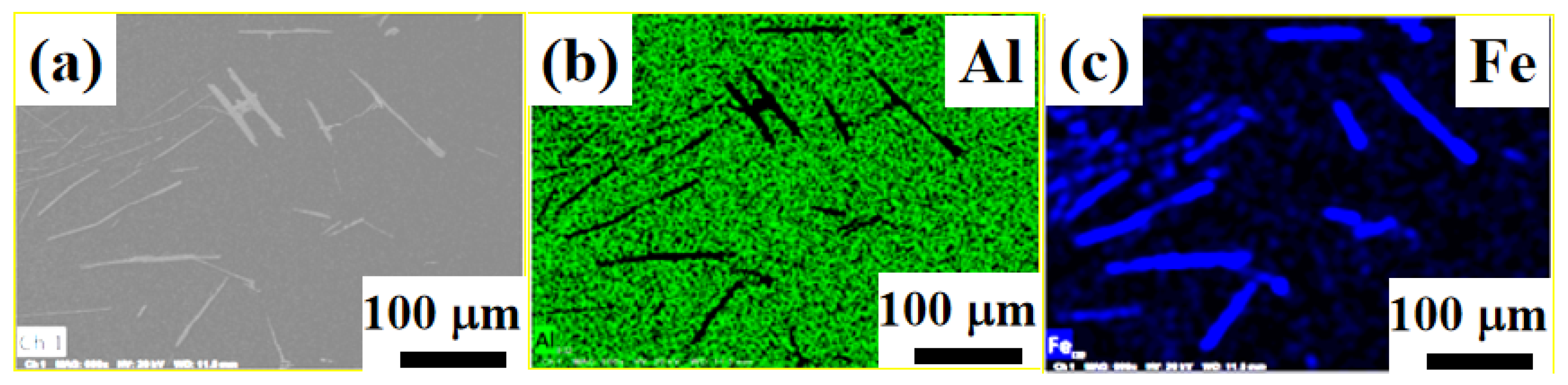
Figure 5, Figure 6 and Figure 7 present the SEM elemental mapping and EDS results of slag specimens collected at the inlet and outlet of the tubular filter for Ce-containing AA 8021 alloy. The elemental distribution of Ce in the inlet mapping (Figure 5) highly overlaps with Ti and V, while showing poor correlation with O, Na, Ca, and K, demonstrating that Ce primarily combines with refractory metallic impurities Ti and V within the melt. Ti is a trace refractory impurity that coexists with V in industrial primary aluminum and recycled scrap. Its measured content is about 0.017–0.018 wt.% in the present alloys, which is at the same level as V.
Figure 5.
SEM elemental mapping results for slag specimens collected at the inlet of the tubular filter for Ce-containing AA 8021 aluminum alloy. (a) SEM image; (b–l) O, Na, Al, Si, Ti, Ce, K, Ca, V, Fe, Zr.
Figure 6.
SEM elemental mapping results for slag specimens collected at the outlet of the tubular filter for Ce-containing AA 8021 aluminum alloy. (a) SEM image; (b,c) Al, Fe.
Figure 7.
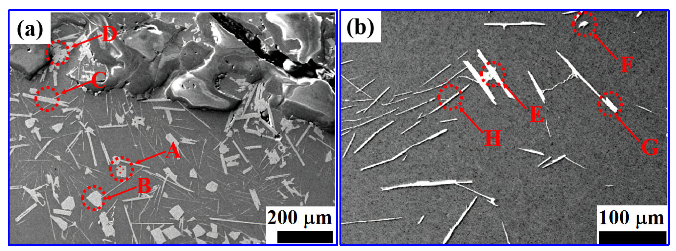
SEM–EDS results of slag specimens from the tubular filter for Ce-containing AA 8021 aluminum alloy: (a) inlet side, (b) outlet side.
At the filter outlet (Figure 6), the number and signal intensity of Ce-enriched impurity agglomeration sites decrease significantly, verifying that such composite slag can be efficiently separated by the filtration unit. Quantitative point EDS analysis (Figure 7, Table 3) reveals that inclusions in the melt can be classified into two main groups. The first group corresponds to multi-component Ce–Ti–V–Al composite inclusions (Points A–E), which contain 14–16 wt.% Ce and are rich in refractory Ti and V. The detected carbon in these composite inclusions mainly originates from industrial melting processes, including carbonization of organic pollutants on recycled scrap surface, carbonaceous components in refining flux, and trace loss of graphite degassing rotors. Carbon mainly enriches in the slag phase and does not dissolve into the aluminum matrix, so it has no adverse effect on the properties of the final ingot matrix. These high-melting intermetallic phases form as Ce captures impurity elements and act as the primary species intercepted by the filter. The second group comprises Al–Fe intermetallic inclusions (Points F–H). Trace Ce is detected in some iron-rich phases, which confirms that Ce can adsorb and accumulate on the surface of iron-rich phases to promote their agglomeration and coarsening.
Table 3.
EDS quantitative results (wt.%) of slag specimens from the tubular filter for the Ce-containing AA 8021 aluminum alloy.
The purification mechanism of Ce in aluminum melts originates from the combined actions of surface adsorption and chemical reactions. On one hand, Ce acts as a surface-active element and segregates at inclusion interfaces to reduce interfacial energy, driving the collision and coarsening of finely dispersed micro-inclusions [14,15]. On the other hand, the high chemical activity of Ce enables the preferential formation of thermodynamically stable, high-melting-point rare earth compounds with O, alkali metals, and other impurities, converting harmful impurities into large-size slag that floats up or is easily filtered [18]. This effect effectively reduced micro-inclusion content in AA 8021 ingots, delivering clear engineering value for lowering rolling pinhole defects and improving product yield. Additionally, the high-melting-point composite phases formed by Ce, Ti and V served as heterogeneous nucleation sites for α-Al during subsequent solidification, further refining the matrix grains.
3.3. As-Cast Microstructure of Alloys
3.3.1. Refinement of Primary α-Al Grains
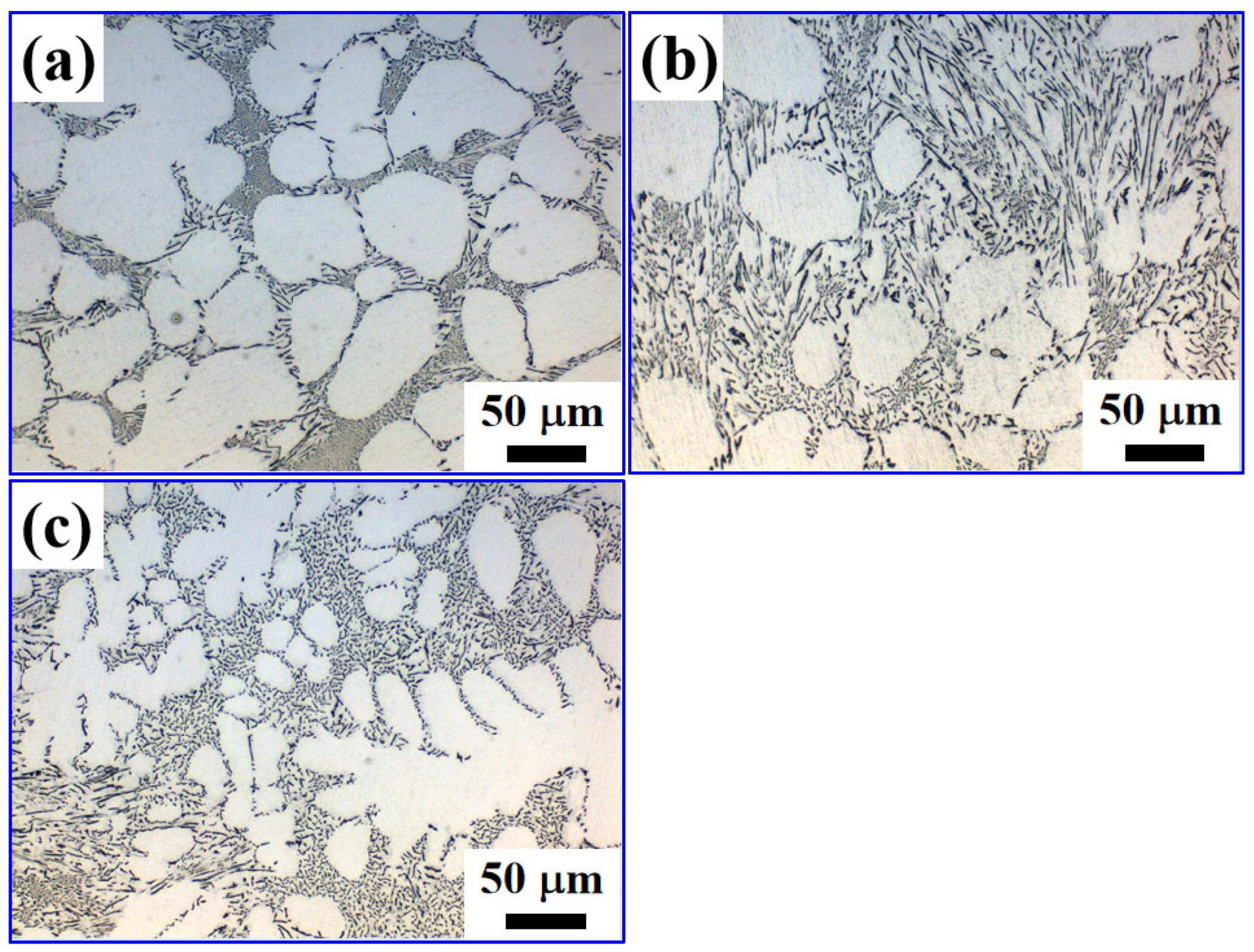
Figure 8 displays the as-cast metallographic microstructures of three Fe–Ce-modified AA 8021 aluminum alloys. The Ce-free S1 alloy exhibited coarse irregular dendrites with poor microstructural homogeneity. After 0.3 wt.% Ce was added (S2), grain sizes decreased markedly, dendritic growth was suppressed, and the microstructure gradually transformed into equiaxed grains. When Fe content was increased to 1.7 wt.% with 0.3 wt.% Ce (S3), the grain refinement effect was further enhanced, accompanied by significantly improved dimensional homogeneity.
Figure 8.
Metallographic micrographs of as-cast ingots of three Fe–Ce modified AA 8021 aluminum alloys: (a) S1; (b) S2; (c) S3.
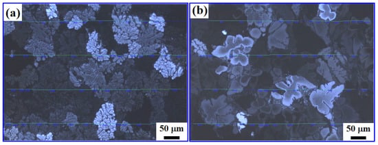
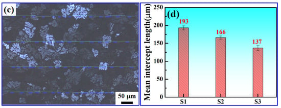
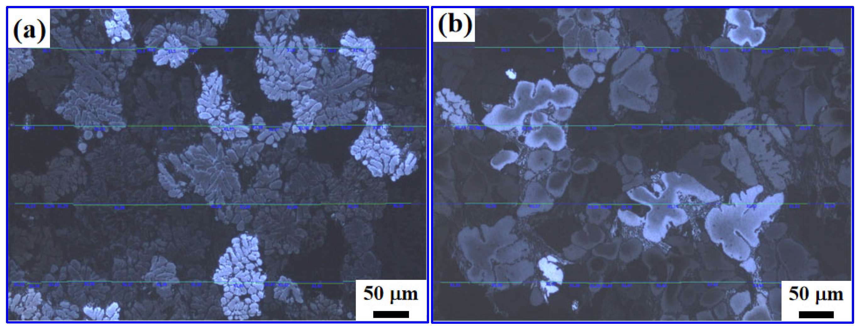
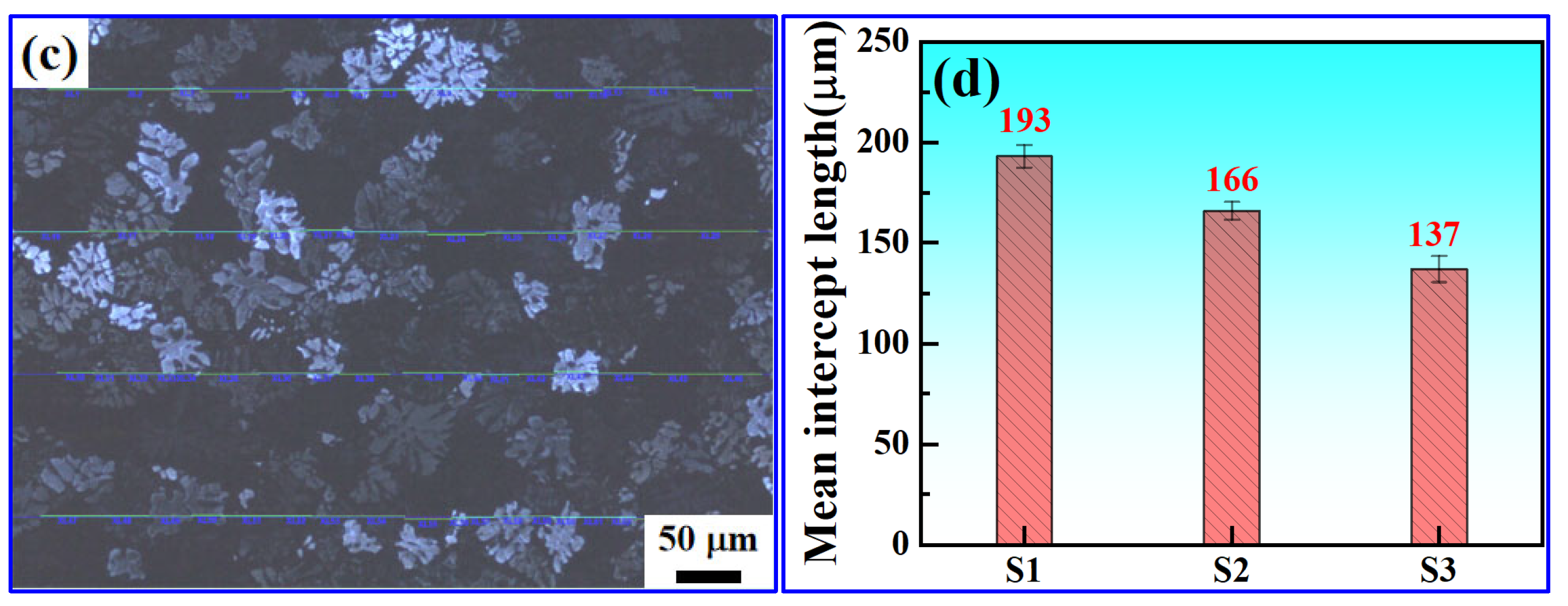
Figure 9 presents the anodized polarized light metallographs and statistical average intercept lengths of primary α-Al grains. The average intercept length of α-Al grains in S1 reached 193 μm; this value decreased to 166 μm for S2, corresponding to a 14% refinement ratio. S3 achieved the smallest mean intercept length of 137 μm, corresponding to a 29% reduction in mean intercept length compared with the baseline S1 alloy, indicating a prominent grain-refinement effect. The refinement mechanism relied on the combined effects of heterogeneous nucleation and growth inhibition. High-melting-point Al–Ce–Ti–V composite phases formed by Ce and impurity Ti/V acted as heterogeneous nucleation substrates for α-Al during solidification and substantially increased nucleation density [14,15]. Meanwhile, Ce enriches at the solid–liquid front to generate constitutional undercooling, restraining directional grain growth and promoting equiaxed grain formation. Moreover, elevated Fe content increased the precipitation volume of iron-rich phases, which pinned grain boundaries during solidification and limited grain growth, contributing to grain refinement together with Ce. These grain-refinement behaviors take place under real industrial impurity conditions containing native Ti and V, which differ from high-purity laboratory alloys described in Ref. [23].
Figure 9.
Anodized polarized light metallographs and mean intercept length statistics of primary α-Al grains for as-cast ingots of three Fe–Ce modified AA 8021 aluminum alloys: (a) S1; (b) S2; (c) S3; (d) mean intercept length of primary α-Al grains.
3.3.2. Evolution of the Morphology and Composition of Iron-Rich Secondary Phases
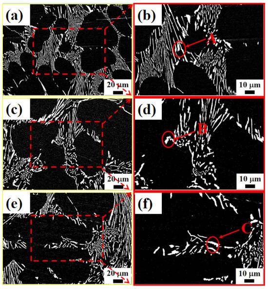
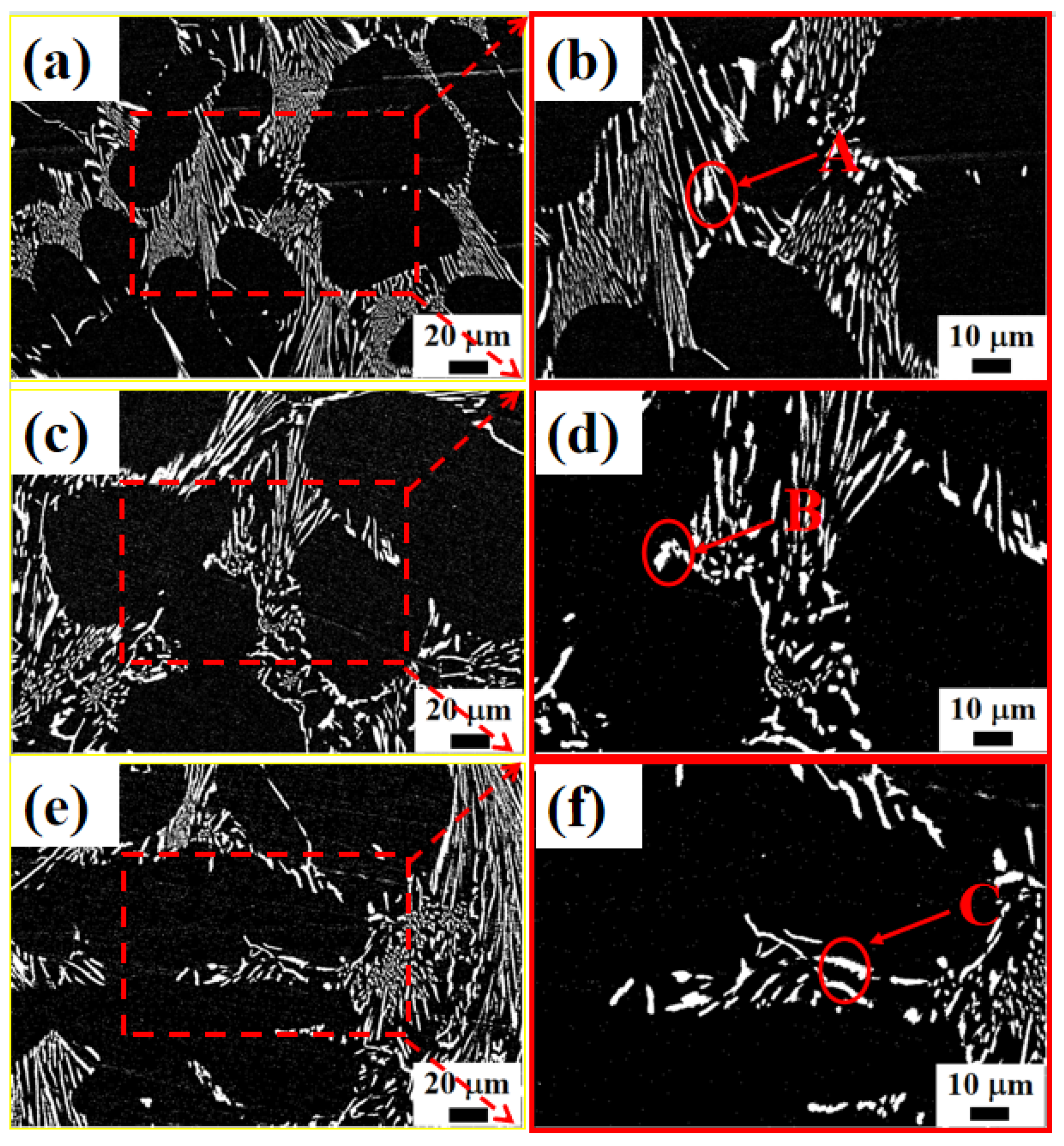
Figure 10 shows the SEM morphologies of iron-rich secondary phases in as-cast three Fe–Ce modified AA 8021 alloys. Iron-rich phases in S1 mainly existed as coarse acicular and flaky structures with lengths of up to tens of micrometers and sharp tips, which severely disrupted the continuity of the aluminum matrix. After adding 0.3 wt.% Ce, the acicular iron-rich phases in S2 were shortened with blunted tips, and some phases transformed into short rod-like and Chinese script-like morphologies, achieving effective phase modification. For S3 with 1.7 wt.% Fe, the volume fraction of iron-rich phases increased, yet their sizes were further refined into granular and short rod-like particles with a dispersed uniform distribution, which greatly mitigated matrix segmentation.
Figure 10.
SEM micrographs of as-cast ingots of three Fe-Ce-modified AA 8021 aluminum alloys: (a) low magnification of S1; (b) high magnification of S1; (c) low magnification of S2; (d) high magnification of S2; (e) low magnification of S3; (f) high magnification of S3.
EDS compositional analysis of iron-rich phases (Table 4) revealed that iron-rich phases in S1 were typical binary Al–Fe intermetallics with ~17.7 wt.% Fe and no detectable Ce. The Ce content in iron-rich phases of S2 reached 1.4 wt.%, confirming partial solid solution of Ce in the iron-rich intermetallics. When Fe content rose to 1.7 wt.% in S3, Fe concentration in iron-rich phases increased to 28.2 wt.% with synchronous Ce enrichment up to 2.2 wt.%. EDS compositional analysis of iron-rich phases (Table 4) revealed that iron-rich phases in S1 were typical binary Al–Fe intermetallics with ~17.7 wt.% Fe and no detectable Ce. The Ce content in iron-rich phases of S2 reached 1.4 wt.%, confirming partial segregation of Ce at iron-rich intermetallics. When Fe content rose to 1.7 wt.% in S3, Fe concentration in iron-rich phases increased to 28.2 wt.% with synchronous Ce enrichment up to 2.2 wt.%. Under industrial solidification conditions, Ce accumulates at the growth front of iron-rich intermetallics and restrains the rapid one-dimensional growth of acicular phases [16,18]. Increasing Fe content provides more nucleation sites for Fe-rich precipitates. Combined with Ce-mediated modification, fine and uniformly dispersed second-phase particles are formed in the ingot matrix. Such phase-modification behavior occurs under industrial melt conditions with inherent Ti-V impurities, rather than the high-purity laboratory environment reported in Ref. [23].
Table 4.
EDS composition results (wt.%) of iron-rich phases in as-cast ingots of three Fe–Ce-modified AA 8021 aluminum alloys.
3.4. Room-Temperature Mechanical Properties and Fracture Mechanisms of As-Cast Alloys
3.4.1. Room-Temperature Tensile Mechanical Properties
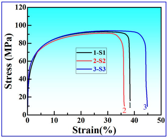
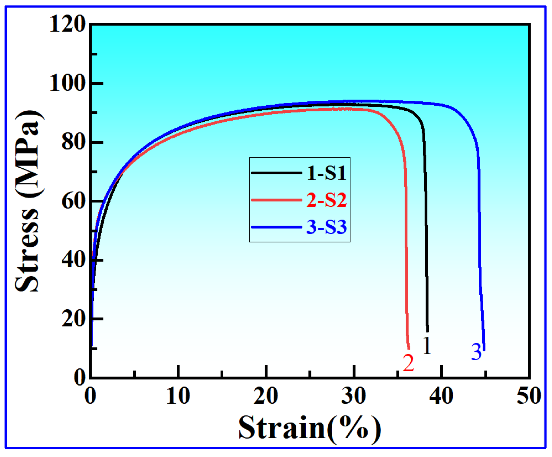
Figure 11 displays the room-temperature tensile stress–strain curves of three Fe–Ce modified AA 8021 alloys, with corresponding mechanical parameters summarized in Table 5. The Ce-free S1 alloy possessed an ultimate tensile strength (UTS) of 92.8 MPa and an elongation of 37.9%. After 0.3 wt.% Ce was added to the 1.5 wt.% Fe matrix (S2), both strength and ductility slightly declined to 89.0 MPa and 35.5%, respectively. When the Fe content was elevated to 1.7 wt.% with 0.3 wt.% Ce (S3), strength and plasticity were simultaneously optimized: the UTS reached 94.0 MPa, and elongation increased to 44.2%, a 16.6% improvement relative to S1, demonstrating the best comprehensive mechanical performance within the present experimental range.
Figure 11.
Room-temperature tensile stress–strain curves of as-cast ingots of three Fe-Ce modified AA 8021 aluminum alloys.
Table 5.
Mechanical properties of as-cast ingots of three Fe–Ce modified AA 8021 aluminum alloys.
Although Ce refines grains and modifies acicular iron-rich phases in S2, hard and brittle Ce–Ti–V composite inclusions formed under industrial melt conditions induce severe stress concentration during tensile deformation and act as preferential crack initiation sites. With only 1.5 wt.% Fe, the amount of iron-rich precipitates is limited, so most Ce preferentially reacts with Ti and V impurities to form independent, relatively large, brittle inclusions. Their adverse effect on plasticity offsets the benefits from microstructural optimization, resulting in minor degradation of both strength and ductility compared with S1 [14,18]. This trend is consistent with the enhanced cleavage fracture features observed on the S2 fracture surface.
For S3 with elevated Fe content paired with 0.3 wt.% Ce, two key changes weaken the detrimental effect of Ce-bearing inclusions and reverse the property trend. First, the increased Fe content substantially raises the volume fraction of iron-rich precipitates. A portion of Ce segregates at the growth front of iron-rich phases to participate in phase modification, thereby dispersing Ce. Accordingly, the Ce–Ti–V composite inclusions in S3 become smaller in size and more dispersed in distribution, and the stress concentration effect triggered by a single inclusion is significantly weakened. Second, S3 achieves more significant grain refinement and more uniformly dispersed second-phase particles. The refined grain structure and dispersed precipitates homogenize the stress distribution during deformation and reduce the stress concentration coefficient around inclusions. Meanwhile, abundant grain boundaries and dispersed particles can deflect and hinder crack propagation; even if microcracks initiate at inclusions, they cannot propagate rapidly.
The beneficial effects of microstructural optimization fully exceed the adverse influence of residual brittle inclusions. It should be noted that the detrimental effect of Ce-bearing inclusions does not disappear in S3, but is greatly weakened and offset by the overall microstructural improvement brought by Fe-Ce combined regulation. As a result, S3 achieves higher strength and elongation than S1 and realizes simultaneous improvement in both properties [11].
3.4.2. Tensile Fracture Morphology and Fracture Mechanisms
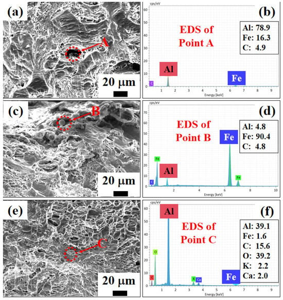
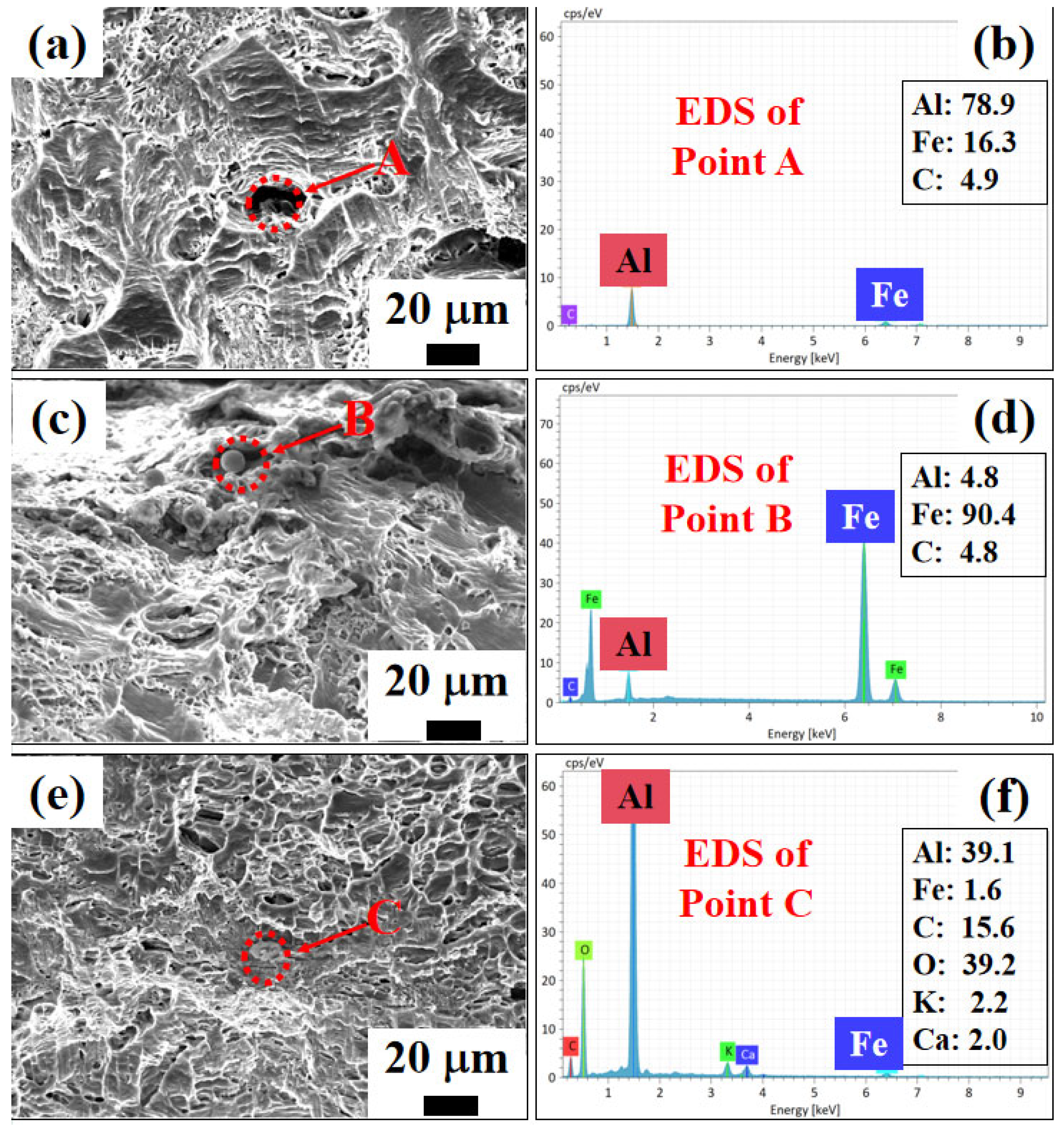
Figure 12 presents the tensile fracture morphologies and point EDS analysis results of the three alloys. The fracture surface of S1 exhibited uneven dimples mixed with local cleavage terraces, and coarse Al–Fe intermetallic particles (Point A) resided at the bottom of dimples. Cracks mostly initiated at the interfaces between iron-rich phases and the matrix, corresponding to a typical mixed ductile–brittle fracture mode [6]. S2 displayed slightly enhanced cleavage features and reduced uniformity of dimple distribution; both iron-rich phases (Point B) and rare earth composite inclusions acted as crack initiation sites, slightly increasing brittleness while maintaining mixed ductile–brittle fracture, consistent with the macroscopic reduction in plasticity. The fracture surface of S3 presented typical ductile fracture characteristics with fine, dense, and uniformly deep dimples. Refined and dispersed iron-rich phases and tiny oxide inclusions (Point C) barely triggered macroscopic crack propagation. Grain refinement and spheroidization of iron-rich phases homogenized stress distribution during deformation and significantly raised resistance to crack initiation and propagation, thereby endowing the alloy with outstanding plastic deformability. Compared with laboratory alloys in Ref. [23], the present industrial ingot contains more complex impurity-related inclusions, which also participate in crack initiation during tensile deformation.
Figure 12.
Room-temperature tensile fracture morphologies and corresponding EDS results of as-cast ingots of three Fe–Ce modified AA 8021 aluminum alloys: (a,b) S1; (c,d) S2; (e,f) S3.
3.5. Electrochemical Corrosion Performance of Alloys
3.5.1. Potentiodynamic Polarization Corrosion Behavior
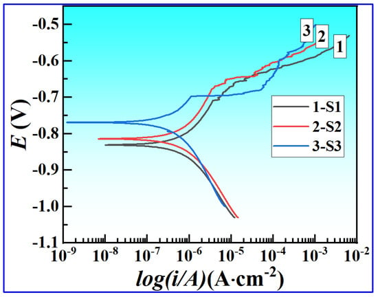
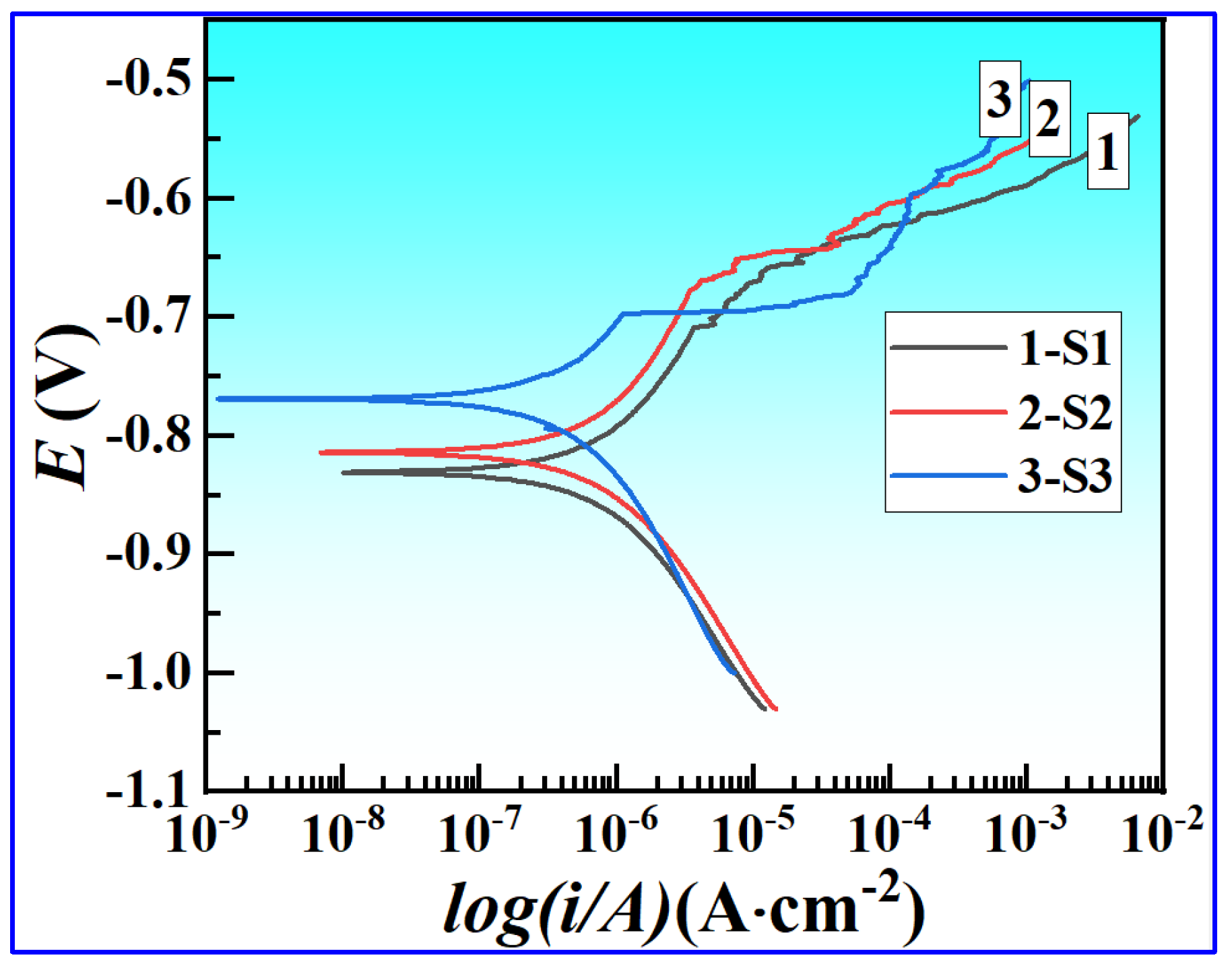
Figure 13 shows the potentiodynamic polarization curves of three Fe–Ce modified AA 8021 alloys in 3.5 wt.% NaCl solution. The corrosion potential (Ecorr) and corrosion current density (Icorr), fitted from the Tafel regions, are listed in Table 6. All polarization curves exhibited typical active dissolution features without stable passivation platforms, consistent with the corrosion behavior of wrought aluminum alloys in neutral chloride-containing solutions. Notably, the S3 alloy exhibits an obvious metastable passivation feature in the anodic branch within the current density range of 10−6 to 10−4 A·cm−2, where the potential changes slightly with increasing current density. This phenomenon arises from the optimized microstructure of S3: grain refinement and Ce surface segregation jointly promote the formation of a more compact passive film, and the transient dynamic balance between film formation and dissolution leads to this flat potential region. With a further increase in anodic potential, the passive film is gradually broken down by chloride ions, and the alloy enters the active dissolution stage.
Figure 13.
Potentiodynamic polarization curves of as-cast ingots of three Fe–Ce-modified AA 8021 aluminum alloys in 3.5 wt.% NaCl aqueous solution.
Table 6.
Corrosion parameters derived from potentiodynamic polarization tests for as-cast ingots of three Fe–Ce-modified AA 8021 aluminum alloys in 3.5 wt.% NaCl aqueous solution.
The Ce-free S1 alloy possessed the most negative corrosion potential (−0.83 V) and the maximum corrosion current density of 5.187 × 10⁻⁷ A·cm−2. After adding 0.3 wt.% Ce at a constant 1.5 wt.% Fe (S2), Ecorr positively shifted to −0.81 V, and Icorr decreased to 3.66 × 10⁻⁷ A·cm−2. Further increasing Fe to 1.7 wt.% with 0.3 wt.% Ce (S3) pushed Ecorr to −0.77 V and drastically reduced Icorr to 1.04 × 10⁻⁷ A·cm−2, only 20% of the value measured for S1. A positive shift in corrosion potential indicates a reduced thermodynamic corrosion tendency, while a decrease in corrosion current density reflects slower corrosion kinetics.
According to the ASTM G102 [26] standard, the average corrosion rate (CR, mm/year) was calculated from the corrosion current density (Icorr) as follows:
where M = 26.98 g/mol is the molar mass of Al, n = 3 is the electron transfer number for Al dissolution, and ρ = 2.70 g·cm−3 is the density of the present AA 8021 series alloy. The calculated corrosion rate values have also been supplemented in the revised Table 6.
As listed in Table 6, S1 corresponds to the highest average corrosion rate of 5.6 × 10⁻³ mm·year−1. With combined Fe and Ce addition, S2 shows a moderate corrosion rate, and S3 achieves the minimum value of 1.1 × 10⁻³ mm·year−1. When considered alongside the evolution of Ecorr and Icorr, these results verify that Fe-Ce composite modification effectively improves the NaCl corrosion resistance of AA 8021 alloys, with the formulation of 1.7 wt.% Fe + 0.3 wt.% Ce delivering the best corrosion resistance among the three examined alloys.
3.5.2. Electrochemical Impedance Spectroscopy (EIS) Analysis
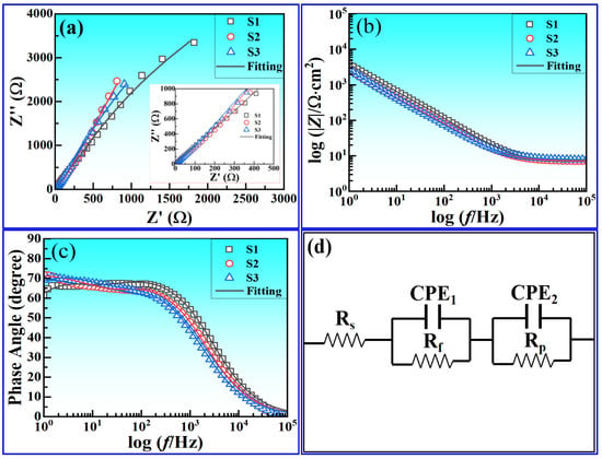
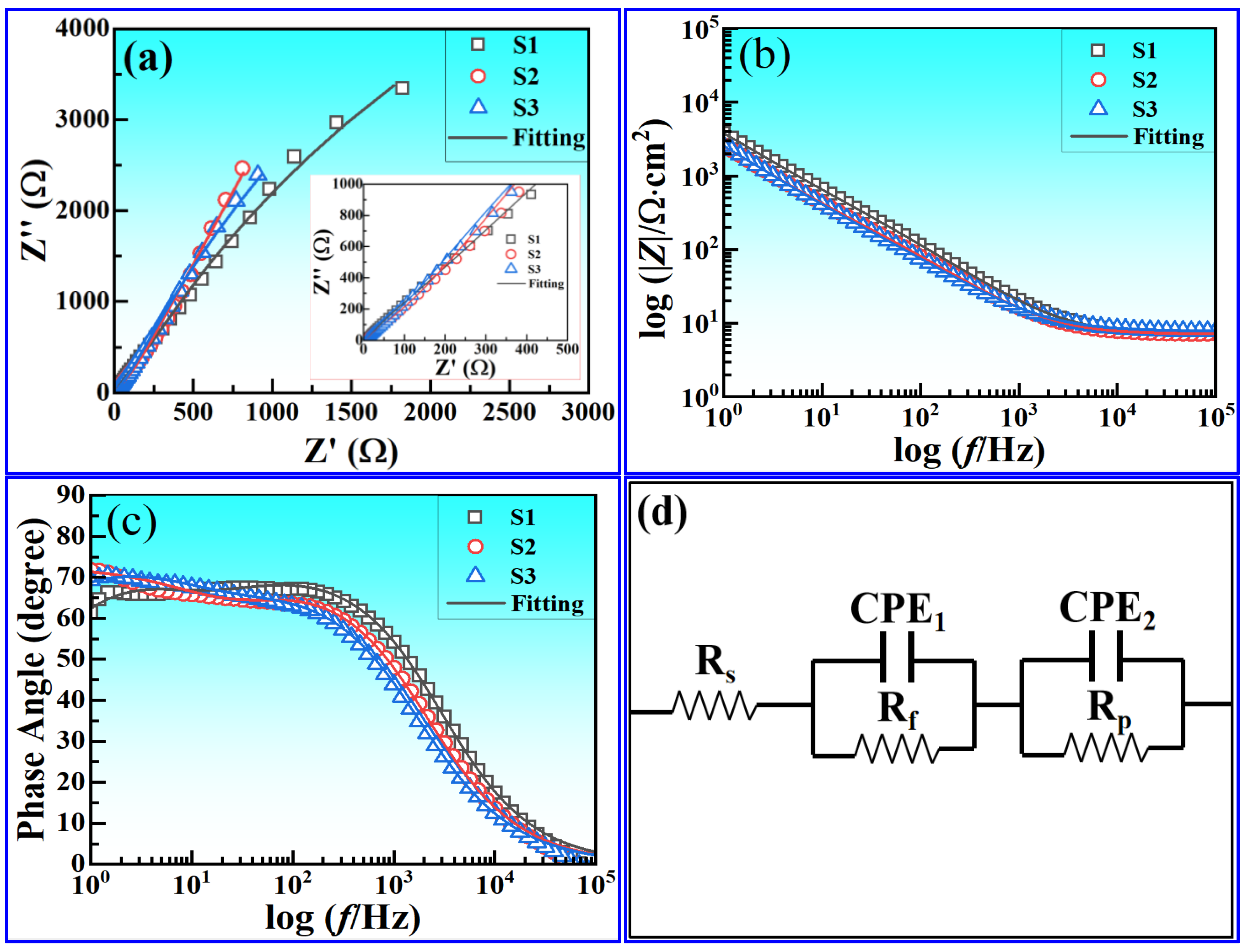
EIS tests were conducted to further reveal interfacial corrosion processes and film protection mechanisms, with results shown in Figure 14. The Nyquist plots (Figure 14a) of all three specimens displayed dual capacitive arcs. The small high-frequency capacitive arc corresponded to impedance responses of the surface passive film, whereas the large low-frequency capacitive arc represented charge transfer processes at the matrix–corrosive medium interface, indicating that corrosion was jointly controlled by surface film and interfacial charge transfer. The diameter of the capacitive arcs gradually increased with Fe–Ce composite addition, and S3 exhibited a remarkably larger arc radius than S1 and S2, directly reflecting its higher corrosion reaction resistance.
Figure 14.
EIS results for as-cast ingots of three Fe–Ce-modified AA 8021 aluminum alloys immersed in 3.5 wt.% NaCl solution: (a) Nyquist plots; (b) Bode modulus plots; (c) Bode phase angle plots; (d) fitted equivalent circuit.
The Bode modulus plots (Figure 14b) followed the order |Z|S3 > |Z|S2 > |Z|S1 across the full frequency range, with prominent differences in the low-frequency impedance modulus, consistent with the trend of corrosion resistance. The Bode phase angle plots (Figure 14c) presented single, broadened peaks for all samples. S3 achieved a higher phase angle peak covering a wider frequency band, demonstrating a more intact surface passive film with superior protective capacity.
A dual-time-constant equivalent circuit Rs(QfRf)(QpRp) (Figure 14d) was adopted to fit EIS data. In this circuit, Rs stands for solution resistance; Qf and Rf correspond to the constant phase element and film resistance of the surface oxide layer, respectively; Qp and Rp represent the constant phase element and polarization resistance of the electric double layer, respectively. The fitting goodness χ2 was less than 7.5 × 10⁻⁴, confirming reliable fitting precision, and the fitted parameters are listed in Table 7. The solution resistance Rs of all samples ranged from 7.0 to 7.7 Ω·cm2, indicating stable test conditions. The surface film resistance Rf sequentially increased from 12.6 Ω·cm2 for S1 to 57.9 Ω·cm2 for S2 and further to 67.6 Ω·cm2 for S3, while polarization resistance Rp rose from 1.9 × 10⁴ Ω·cm2 for S1 to 2.2 × 10⁴ Ω·cm2 for S2 and 2.6 × 10⁴ Ω·cm2 for S3. Synchronous elevation of film resistance and polarization resistance demonstrated that Fe–Ce composite modification both enhanced the compactness and barrier performance of surface passive films and increased the interfacial charge transfer resistance for corrosion reactions, inhibiting corrosion progress from multiple dimensions.
Table 7.
Fitted EIS parameters for as-cast ingots of three Fe–Ce modified AA 8021 aluminum alloys in 3.5 wt.% NaCl solution.
As the barrier layer of aluminum plastic film for soft-pack lithium-ion batteries, the integrity of passive films and pitting resistance of AA 8021 alloy directly determine the long-term service safety of battery cells, and mature evaluation systems for electrochemical corrosion of this alloy system have been reported in the existing literature [23]. Combined with microstructural evolution rules, the mechanisms through which Fe–Ce composite modification improves the NaCl corrosion resistance of AA 8021 alloys can be summarized in two aspects:
Optimized second-phase morphology weakens micro-galvanic corrosion. Iron-rich intermetallic phases possessed a higher electrode potential than the aluminum matrix and acted as cathodes to form micro-galvanic couples with the matrix, accelerating local matrix dissolution and serving as core pitting initiation sites [8,27]. Ce addition refined and blunted coarse acicular iron-rich phases, reducing the effective cathode area and electric field concentration effects. Combined with the dispersed distribution of second phases induced by elevated Fe content, the driving force of local micro-galvanic corrosion was drastically weakened, suppressing pitting initiation and propagation [27].
Grain refinement and Ce surface segregation jointly stabilize passive films. Grain refinement increased grain boundary density and provided more nucleation sites for passive films, facilitating the formation of continuous and uniform surface oxide layers and lowering the penetration probability of Cl− ions [28,29]. Meanwhile, Ce, as a surface-active element, segregated toward the alloy surface during corrosion. On one hand, it competed with corrosive Cl− for adsorption sites; on the other hand, Ce-containing oxides/hydroxides precipitated at film defects to fill pores in passive films, improving compactness and self-repair capacity and further hindering penetration of corrosive media into the matrix [20,30]. For S3, the optimal grain refinement and iron-rich phase modification generated the most intact and stable passive film, thus delivering the best corrosion resistance. The above corrosion behavior was observed in industrial ingots with complex impurity backgrounds, which cannot be directly reproduced in high-purity laboratory alloys, as shown in Ref. [23].
3.6. Comprehensive Regulatory Mechanism Under Combined Fe and Ce Additions
Compared with previous studies focusing on single Ce modification in laboratory-scale Al–Fe alloys, this work provides three novel academic insights under industrial production conditions. First, a bidirectional complementary regulation mode between Fe and Ce is proposed based on the present experimental observations: Ce mitigates matrix segmentation caused by high Fe content via second-phase modification, while elevated Fe content provides dispersion strengthening and grain boundary pinning. It should be noted that due to the absence of a 1.7 wt.% Fe Ce-free industrial ingot in this work, the individual contributions of Fe and Ce cannot be fully quantitatively separated. Whether there is a mutual amplification effect between Fe and Ce still requires further verification by more systematic composition experiments. Second, the dual-function nature of Ce-Ti-V composite phases formed under industrial impurity backgrounds is confirmed: they act as both filterable slag for melt purification and heterogeneous nucleation substrates for grain refinement. Third, the bidirectional complementary regulation mode between Fe and Ce is further emphasized based on the present experimental observations: Ce mitigates matrix segmentation caused by high Fe content via second-phase modification, while elevated Fe content provides dispersion strengthening and grain boundary pinning. It should be noted that due to the absence of a 1.7 wt.% Fe Ce-free industrial ingot in this work, the individual contributions of Fe and Ce cannot be fully quantitatively separated. Whether there is a mutual amplification effect between Fe and Ce still requires further verification by more systematic composition experiments.
Based on systematic characterization of solidification thermal behavior, melt purification, as-cast microstructure evolution, and macroscopic property responses, the regulatory effect of combined Fe and Ce additions on AA 8021 alloy cannot be simply regarded as the linear superposition of individual functions. Instead, it presents a multi-stage regulatory process covering melt purification, solidification nucleation, second-phase modification, and property optimization, which simultaneously improves the metallurgical quality and comprehensive service performance of as-cast ingots.
At the melt purification stage, highly reactive Ce preferentially reacts with refractory Ti and V impurities in the melt to form high-melting-point Al-Ce-Ti-V multi-element intermetallic phases. This reaction delivers two key benefits: on one hand, scattered microscale refractory impurities agglomerate into large slag particles that can be easily captured by industrial ceramic filters, realizing deep purification of molten aluminum [14,19]; on the other hand, the newly formed high-melting composite particles serve as heterogeneous nucleation sites for α-Al during solidification, laying a foundation for subsequent grain refinement. Increasing Fe content further increases the nucleation substrates of iron-rich precipitates, which work together with Ce-generated nucleation sites to enhance the solidification nucleation rate.
At the solidification microstructure regulation stage, Ce and Fe exert joint effects to optimize the alloy microstructure. Ce accumulates at the solid–liquid interface and induces constitutional undercooling, which suppresses unidirectional dendritic growth and promotes the transition from dendrites to equiaxed grains. Meanwhile, Ce segregates at the growth boundaries of iron-rich phases and hinders the preferential elongation of acicular Al3Fe intermetallics, transforming them into short rod-like and granular particles [16]. Although higher Fe loading naturally increases the volume fraction of iron-rich phases and brings risks of phase coarsening and matrix discontinuity, Ce modification fully offsets these drawbacks, allowing the additional iron-rich phases to precipitate as fine, uniformly dispersed particles within the matrix. These dispersed precipitates also pin grain boundaries and restrict grain growth, further enhancing the grain-refining effect of Ce.
For the S2 alloy (1.5 wt.% Fe + 0.3 wt.% Ce), hard, brittle, rare earth composite inclusions induce severe stress concentration that offsets part of the microstructural advantages, resulting in slightly degraded mechanical properties. In comparison, the S3 alloy (1.7 wt.% Fe + 0.3 wt.% Ce) fully exploits the dispersion strengthening and grain-boundary pinning effects from higher Fe content, which positively cooperate with Ce-mediated grain refinement and second-phase modification to achieve comprehensive microstructural improvement.
At the macroscopic property response stage, multi-scale microstructural optimization translates into synchronous enhancement of mechanical performance and corrosion resistance. Mechanically, the combined effects of grain-boundary strengthening and dispersion hardening moderately improve tensile strength, while spheroidized iron-rich phases and homogeneous grain distribution greatly reduce stress concentration and lower the probability of crack initiation during plastic deformation, which significantly improves ductility and breaks the classic strength–ductility trade-off. In terms of corrosion resistance, finely dispersed iron-rich intermetallics weaken the driving force of micro-galvanic corrosion and reduce potential pitting initiation sites. Grain refinement also promotes the formation of continuous, compact surface passive films with better stability and self-repair capability [20,26]. Collectively, these microstructural adjustments significantly improve the corrosion resistance of the alloy in sodium chloride environments.
In summary, under combined Fe and Ce additions, Ce exerts dual functions of impurity purification and second-phase modification to mitigate microstructural defects induced by high Fe content; in turn, increased Fe levels provide dispersion strengthening effects that amplify the microstructural optimization benefits of Ce. This proposed bidirectional complementary regulation mode achieves multiple integrated targets: a purer melt, refined matrix grains, uniformly dispersed secondary phases, and excellent comprehensive performance. The 1.7 wt.% Fe + 0.3 wt.% Ce formulation is confirmed as the best-performing composition scheme within the present experimental range for this industrial melting and casting production line.
Notably, this work still has two limitations that need to be further addressed. First, only three composition schemes were investigated in the present industrial trial, and the 1.7 wt.% Fe Ce-free control group is not included; the individual contributions of Fe and Ce have not been fully quantitatively separated. Second, all characterizations were performed on as-cast flat ingots, and there remains a processing gap to the final battery foil product. The initial as-cast microstructure optimization is a critical prerequisite for reducing rolling cracking risk, improving deformation uniformity and reducing foil defects such as pinholes and streaks, but the microstructure and property evolution during subsequent hot rolling, cold rolling and annealing still needs systematic verification. Although our previous laboratory small-crucible experiments with gradient Ce additions at a fixed 1.7 wt.% Fe confirm the intrinsic modification capacity of Ce, laboratory findings cannot be directly extrapolated to the 100-ton industrial-scale solidification conditions reported herein. More composition schemes and full-process foil rolling trials will be carried out in follow-up research to further refine the regulatory mechanism and connect upstream ingot optimization with final product performance.
4. Conclusions
In this work, Fe–Ce composite microalloying was adopted to optimize the as-cast microstructure and service properties of industrially cast AA 8021 battery-foil aluminum alloy. Based on systematic investigations of solidification thermal behavior, melt purification efficiency, microstructure evolution, mechanical properties, and corrosion resistance, the multi-stage microstructure-property evolution laws of Fe–Ce combined modification under industrial production conditions were clarified, and the main conclusions are as follows:
- (1)
- Combined Fe and Ce microalloying can effectively regulate the solidification thermal behavior and as-cast microstructure of AA 8021 aluminum alloy. Cerium reacts with Ti, V and other refractory impurities in molten aluminum to form high-melting-point composite intermetallics, which act as heterogeneous nucleation sites to refine matrix grains. Meanwhile, Ce segregates at the growth interfaces of iron-rich phases and transforms coarse, acicular Al3Fe phases into short, rod-like, and granular particles. Combined with the precipitation of abundant iron-rich phases and grain boundary pinning induced by 1.7 wt.% Fe, the mean intercept length of α-Al grains in the optimized alloy decreases to 137 μm, representing a 29% reduction compared with the reference alloy, which shows an obvious grain-refinement effect. In addition, the alloy exhibits an elevated melting peak temperature and significantly improved high-temperature thermal stability.
- (2)
- Cerium enhances the melt purification capacity of industrial melting and casting systems via the combined actions of adsorption and chemical reaction. Ce causes fine micro-inclusions to agglomerate and grow into large-sized slag, which can be readily intercepted by ceramic filters to reduce native defects in as-cast ingots. With a composition of 1.7 wt.% Fe and 0.3 wt.% Ce, superposed dispersion strengthening and grain refinement offset the adverse stress concentration effect induced by brittle rare earth composite inclusions. The alloy delivers an ultimate tensile strength of 94.0 MPa and an elongation of 44.2%, and its fracture mode evolves from mixed ductile–brittle fracture to typical ductile fracture, achieving synchronous improvement in strength and ductility.
- (3)
- Fe–Ce composite modification remarkably improves the corrosion resistance of AA 8021 aluminum alloy in NaCl environments. Refined and dispersed iron-rich phases weaken micro-galvanic corrosion between the matrix and intermetallic precipitates and reduce pitting initiation sites. Grain refinement together with surface segregation of Ce promotes the formation of continuous, dense passive films with enhanced barrier capacity and self-repair performance. The alloy with 1.7 wt.% Fe and 0.3 wt.% Ce achieves a corrosion current density as low as 1.04 × 10⁻⁷ A·cm−2. This composition system is compatible with 100-ton industrial melting and casting lines, which can provide theoretical guidance and engineering references for the stable mass production of high-performance aluminum foil for lithium-ion battery packaging.
Author Contributions
Methodology, L.S., B.C. and B.R.; investigation, L.S., B.R. and A.J.; data curation, L.S. and Z.L.; writing—original draft preparation, L.S.; writing—review and editing, Z.L. and B.C.; project administration, B.R., A.J. and Z.L.; funding acquisition, B.R. All authors have read and agreed to the published version of the manuscript.
Funding
This research was funded by the Henan Provincial Science and Technology Research Plan Project, grant number 232102231007.
Data Availability Statement
The original contributions presented in this study are included in the article. Further inquiries can be directed to the corresponding authors.
Conflicts of Interest
Lei Shi was employed by the Henan Zhongfu Industrial Co., Ltd. The remaining authors declare that the research was conducted in the absence of any commercial or financial relationships that could be construed as a potential conflict of interest.
References
- Xu, S.A.; Wang, S.N.; Gu, Y.Y. Microstructure and Adhesion Properties of Ce Conversion Coating Modified with Silane Coupling Agent on Lithium-Ion Battery Aluminum Foil. Results Phys. 2019, 13, 102262. [Google Scholar] [CrossRef] [Scilit]
- Xia, X.F.; Gu, Y.Y.; Xu, S.A. Titanium Conversion Coatings on AA 8021 Aluminum Foil for Lithium-Ion Battery Packaging. Appl. Surf. Sci. 2017, 419, 447–453. [Google Scholar] [CrossRef] [Scilit]
- Liang, C.S.; Lv, Z.F.; Zhu, Y.L.; Xu, S.A.; Wang, H. Protection of AA 8021 Aluminium Foil via Molybdate-Based Conversion Coatings. Appl. Surf. Sci. 2014, 288, 497–502. [Google Scholar] [CrossRef] [Scilit]
- Zhao, X.Y.; Jin, T.; Ding, L.P.; Wan, B.W.; Lei, X.C.; Xu, C.Z.; Zhang, C.L.; Jia, Z.H.; Liu, Q. Combined Effects of Cold Rolling and Homogenization on Microstructures and Mechanical Properties of Twin-Roll Cast 8021 Aluminum Alloy. J. Alloys Compd. 2023, 937, 168385. [Google Scholar] [CrossRef] [Scilit]
- Wang, W.; Sun, Q.R.; Zhang, K.M. Modification Mechanism and Mechanical Properties of 8021 Aluminum Alloys. J. Mater. Eng. Perform. 2025, 34, 21886–21892. [Google Scholar] [CrossRef] [Scilit]
- Lu, L.; Dahle, A.K. Iron-Rich Intermetallic Phases and Their Contribution to Casting Defect Formation in Hypoeutectic Al–Si Alloys. Metall. Mater. Trans. A 2005, 36, 819–835. [Google Scholar] [CrossRef] [Scilit]
- Khalifa, W.; Samuel, F.H.; Gruzleski, J.E. Iron Intermetallic Phases in the Al-Rich Region of the Al–Si–Fe Ternary System. Metall. Mater. Trans. A 2003, 34, 807–825. [Google Scholar]
- Ikeuba, A.I.; Njoku, C.N.; Ekerenam, O.O.; Njoku, D.I.; Udoh, I.I.; Daniel, E.F.; Uzoma, P.C.; Etim, I.N.; Okonkwo, B.O. Review on Electrochemical and Galvanic Corrosion of Typical Intermetallic Compounds in Aluminium Alloys. RSC Adv. 2024, 14, 31921–31953. [Google Scholar] [CrossRef] [Scilit]
- Chen, W.; Chen, M.H.; Jin, X.J.; Zhang, P. Effect of Annealing Heating Rate on Microstructure and Texture Evolution of AA 8021 Aluminum Foil. Mater. Res. Express 2020, 7, 096514. [Google Scholar] [CrossRef] [Scilit]
- Chen, W.; Zhao, P.Z.; Zhou, Y.L.; Pan, Y.F. Effects of Homogenization Regimes on Microstructures of Twin-Roll Cast AA 8021 Aluminum Alloy Foil Stock. Mater. Sci. Forum 2016, 877, 296–302. [Google Scholar] [CrossRef] [Scilit]
- Jin, X.J.; Zhao, P.Z.; Feng, D. Grain Size Dependence of Mechanical Properties and Formability for AA 8021 Aluminum Foil. J. Mater. Eng. Perform. 2022, 31, 10354–10366. [Google Scholar] [CrossRef] [Scilit]
- Sun, Q.R.; Wang, W. Effects of Sr and Nd Additions on Microstructure and Properties of 8021 Aluminum Alloy. Trans. Mater. Heat Treat. 2024, 45, 84–90. (In Chinese) [Google Scholar]
- Sun, Q.R.; Wang, W. Effect of Microalloying on Hot Deformation Behavior of 8021 Aluminum Alloy. Russ. J. Nonferrous Met. 2024, 2, 69–80. [Google Scholar] [CrossRef] [Scilit]
- Czerwinski, F. Cerium in Aluminum Alloys: A Review. J. Mater. Sci. 2020, 1, 24–72. [Google Scholar] [CrossRef] [Scilit]
- Zhao, W.J.; Liu, G.Y.; Zhang, S.Q.; Ren, Y.S.; Yuan, K.; Yu, B.X.; Wang, B.; Xin, H.; Lv, G.Q.; Chen, X.H.; et al. Rare Earth Microalloying in Aluminum Alloys: Microstructure Evolution and Performance Enhancement Mechanisms—A Review. J. Mater. Res. Technol. 2026, 41, 2839–2869. [Google Scholar] [CrossRef] [Scilit]
- Vončina, M.; Medved, J.; Steinacher, M.; Ozimič, K. Influences of La and Ce Additions on Solidification Behaviour of Al–Fe Alloys. J. Therm. Anal. Calorim. 2025, 150, 873–882. [Google Scholar] [CrossRef] [Scilit]
- Qu, H.; Liu, W.D.; Jiang, X.Y. EET Analysis of Melt Structure and Formation of Main Strengthening Phases in Al–Fe–Ce Alloys. Chin. J. Rare Met. 2020, 44, 1003–1008. (In Chinese) [Google Scholar]
- Li, S.X.; Jiang, H.X.; Li, Y.Q.; Zhang, L.L.; Sun, H.; He, J.; Jiang, H.C.; Zhao, J.Z. Effect of Rare Earth Ce on Microstructures and Mechanical Properties of Al–Fe Alloys. Sci. China Technol. Sci. 2023, 66, 3317–3327. [Google Scholar]
- Mu, X.W.; Du, K.; Lv, C.; Xu, G.M. Influence of Ce Content on Solidification Microstructure of 8021 Aluminum Alloy. Light Alloy Fabr. Technol. 2022, 50, 20–23. (In Chinese) [Google Scholar]
- Zhou, X.J.; Xiong, H.Q. Corrosion Performance of Al–Ce Alloys in 3.5 wt.% NaCl Solution. Int. J. Electrochem. Sci. 2022, 17, 220137. [Google Scholar]
- Li, C.; Luo, Y.T.; Zhou, Q.S.; Han, M.N.; Sha, S.H.; Xu, X.J. Effect of Ce Content on Microstructure and Corrosion Resistance of High-Strength AlZnMgCuZrTi Alloys. Trans. Nonferrous Met. Soc. China 2025, 35, 2148–2163. [Google Scholar] [CrossRef] [Scilit]
- Ji, H.H.; Wu, C.F.; Hu, D.L.; Wang, Y.Y.; Lei, Y.G. Research on Melting and Casting Process of Large-Size 8021 Aluminum Alloy Flat Ingots. Alum. Process. 2025, 6, 35–41. (In Chinese) [Google Scholar]
- Shi, L.; Liu, Z.; Jiang, A.; Cai, B.; Ren, B. Ce-Mediated Second-Phase Reconstruction for Coupled Regulation of Mechanical and Corrosion Properties of As-Cast 8021 Aluminum Alloy Billets for Battery Foil. Coatings 2026, 16, 645. [Google Scholar] [CrossRef] [Scilit]
- GB/T 6394-2002; Metal-Methods for Estimating the Average Grain Size. Standards Press of China: Beijing, China, 2002.
- GB/T 6397-1986; Metallic Materials-Test Pieces for Tensile Testing. Standards Press of China: Beijing, China, 1986.
- ASTM G102-23; Standard Practice for Calculation of Corrosion Rates and Related Information from Electrochemical Measurements. ASTM International: West Conshohocken, PA, USA, 2023.
- Araujo, J.V.d.S.; Chen, J.; Costa, I.; Zhou, X. Localized Corrosion of Anodized Aluminium Alloys: The Impact of Constituent Particle-Induced Defects in Anodic Films. Corros. Sci. 2025, 252, 112961. [Google Scholar] [CrossRef] [Scilit]
- Bui, A.T.; Ngo, H.Q.T.; Nguyen, T.H. A Comprehensive Review of Ultrasonic Treatment for Aluminium Alloy Casting. Discov. Mech. Eng. 2026, 5, 32. [Google Scholar] [CrossRef] [Scilit]
- Wang, P.J.; Ma, L.W.; Cheng, X.Q.; Li, X.G. Grain Refinement Effects on Corrosion Behavior of Metallic Materials: A Review. Int. J. Miner. Metall. Mater. 2021, 28, 1112–1126. [Google Scholar] [CrossRef] [Scilit]
- Liu, S.; Zhao, T.; Fu, J.; Zu, Q. Inoculants for Aluminium Alloys: A Review. Materials 2023, 16, 5500. [Google Scholar] [CrossRef] [Scilit]

Disclaimer/Publisher’s Note: The statements, opinions and data contained in all publications are solely those of the individual author(s) and contributor(s) and not of MDPI and/or the editor(s). MDPI and/or the editor(s) disclaim responsibility for any injury to people or property resulting from any ideas, methods, instructions or products referred to in the content. |
© 2026 by the authors. Licensee MDPI, Basel, Switzerland. This article is an open access article distributed under the terms and conditions of the Creative Commons Attribution (CC BY) license.