


Abstract
The effects of Ru on Re segregation and low-cycle fatigue (LCF) behavior were investigated in two model single-crystal superalloys, Ni-8.5Al-4Re and Ni-8.5Al-4Re-2Ru (wt.%). Microstructural morphology, elemental distribution, fatigue deformation behavior, and dislocation structures were systematically compared, and density functional theory (DFT) calculations were performed to examine the associated atomic and electronic effects. The results show that Re segregates at the γ′/γ interface in both alloys, whereas the addition of 2 wt.% Ru reduces the extent of interfacial Re segregation. The Gibbsian interfacial excess of Re decreases from 18.19 ± 1.75 to 11.42 ± 0.01 atom nm−2, while the maximum interfacial Re concentration ratio decreases from 1.36 ± 0.01 to 1.17 ± 0.02 after Ru addition. DFT calculations further show that Re increases the unstable stacking-fault energy of the γ′/γ interface by 10.34% relative to the unalloyed interface, whereas the corresponding increase is 5.05% in the Re–Ru co-doped system. Fatigue-deformed NiAlRe exhibits interfacial dislocation networks along the γ′/γ interfaces, whereas more extensive dislocation penetration into the γ′ precipitates is observed in NiAlReRu. At a strain amplitude of 0.6%, the Ru-containing alloy exhibits a lower cyclic stress response and more pronounced crack initiation and coalescence. These results show that Ru modifies the interfacial segregation behavior of Re and is associated with changes in the post-fatigue dislocation structures and high-temperature LCF response of the model superalloys.
1. Introduction
With the rapid development of aviation, energy, and other advanced technologies, increasingly demanding requirements have been imposed on the performance of superalloys. As an important class of high-temperature structural materials, nickel-based single-crystal superalloys (SXs) have been extensively used in hot-section components, especially aero-engine turbine blades, owing to their excellent high-temperature strength, superior oxidation resistance, and outstanding hot-corrosion resistance [1,2,3]. In recent years, the continuous increase in turbine inlet temperature, driven by the demand for higher aero-engine thrust-to-weight ratios, has placed higher requirements on the high-temperature capability of SXs. In the development of nickel-based SXs, compositional optimization has been regarded as one of the most effective approaches to tailoring microstructure and improving mechanical performance. For example, second-generation nickel-based SXs developed in the 1990s, such as PWA1484 and CMSX-4, introduced approximately 3 wt.% Re, which increased the temperature capability by about 30 °C compared with first-generation alloys. Subsequently, third-generation nickel-based SXs, represented by TMS-75 and CMSX-10, further increased the Re content to approximately 6 wt.%, leading to an improvement in temperature capability of about 60 °C relative to first-generation alloys [4,5]. However, although refractory elements such as Re can significantly enhance creep resistance, excessive addition may deteriorate microstructural stability and promote the precipitation of detrimental topologically close-packed (TCP) phases. To overcome this issue, Ru was introduced to suppress TCP phase formation, which contributed to the development of fourth-generation and fifth-generation nickel-based SXs containing approximately 3 wt.% and 6 wt.% Ru, respectively, such as TMS-138 and TMS-162.
In this context, Re and Ru, as representative alloying elements in advanced nickel-based SXs, have attracted considerable attention, particularly regarding their partitioning behavior and interaction mechanisms. However, the influence of Ru on Re distribution remains highly debated. Several different effects of Ru on Re partitioning have been reported in previous studies: (1) Ru reduces Re supersaturation in the γ matrix [6,7,8]; (2) Ru exerts only a limited influence on Re partitioning in some alloy systems [9,10]; and (3) Ru–Cr interactions may induce the reverse partitioning of Re [11]. These inconsistent conclusions mainly arise from experimental observations in different multicomponent superalloys using characterization techniques such as atom probe tomography (APT, CAMECA, Paris, France) and energy-dispersive spectroscopy (EDS, Oxford Instruments, Abingdon, UK). Nevertheless, explanations for the underlying mechanisms are still limited. Among these studies, Shu et al. [6] speculated that Re atoms surrounding Ru atoms dissolved in the γ′ phase may be influenced by d-orbital hybridization, thereby reducing Re segregation in the γ matrix [12]. However, a clear understanding of how Ru regulates Re partitioning and segregation behavior, especially from the atomic and electronic perspectives, has not yet been fully established.
This unresolved ambiguity in Re–Ru interaction mechanisms restricts the rational design of advanced nickel-based SXs. To clarify this issue, two simplified model superalloys, NiAlRe and NiAlReRu, distinguished by the absence or presence of Ru addition, were selected in this study to minimize the interference from other alloying elements. By comparatively investigating their microstructural morphology, elemental distribution, and low-cycle fatigue (LCF) behavior, this work aims to establish the relationship between Re/Ru distribution at γ′/γ interfaces and the resulting mechanical response. Furthermore, density functional theory (DFT) calculations were employed to reveal the underlying atomic- and electronic-level mechanisms. Specifically, this study focuses on: (1) clarifying the effect of Ru on Re segregation at the γ′/γ interface; (2) establishing the relationship between interfacial segregation behavior and LCF behavior at 1000 °C; and (3) elucidating how Re/Ru distribution affects interfacial dislocation behavior and fatigue damage evolution.
2. Material and Methods
2.1. Alloy Preparation
Two model superalloys with nominal compositions of Ni-8.5Al-4Re (wt.%) and Ni-8.5Al-4Re-2Ru (wt.%) were fabricated as [001]-oriented SX rods via directional solidification (Table 1). In this article, these alloys are abbreviated as NiAlRe and NiAlReRu, respectively. The latter alloy was designed by introducing 2 wt.% Ru into the base NiAlRe system to isolate the effects of Ru addition. Both model alloys underwent an identical multi-stage heat treatment as follows:
- (1)
- Solution treatment: 1290 °C/1 h + 1300 °C/2 h + 1315 °C/4 h (air cooling, AC).
- (2)
- Two-step aging: 1050 °C/4 h (AC) + 870 °C/36 h (AC).
Table 1.
Nominal compositions of the model superalloys (wt.%).
It is noteworthy that the post-solidification heat treatment is critical for tailoring the γ′/γ dual-phase microstructure in SXs to achieve performance optimization. The aforementioned heat treatment process was determined through the following steps:
(1) Preliminary determination of heat treatment temperature range based on experimentally measured DSC curves and simulated characteristic phase transformation temperatures (JMatPro, version 16.0, Sente Software Ltd., Guildford, UK).
(2) Stepwise solution treatment with reference to the standard heat treatment process for second-generation commercial SX DD6: 1290 °C/1 h + 1300 °C/2 h + 1315 °C/4 h (AC).
(3) Multiple aging treatments (Table 2) applied to the solution-treated alloy, followed by microstructural characterization using field-emission scanning electron microscopy (SEM, Hitachi SU-70, Hitachi High-Tech Corporation, Tokyo, Japan). With γ′ cuboidal morphology, distribution uniformity, and size consistency as evaluation criteria (quantified via Image J (version 1.54p) and MIPAR software (version 6.0)), the optimal aging process was identified as 1050 °C/4 h (AC) + 870 °C/36 h (AC).
Table 2.
Different aging heat treatment processes.
The γ′/γ morphology of both model superalloys after heat treatment was characterized using field-emission scanning electron microscopy (SEM, Hitachi SU-70, Hitachi High-Tech Corporation, Minato-ku, Tokyo, Japan) at an accelerating voltage of 10 kV and a working distance of 7.8 mm. For quantitative microstructural analysis, MIPAR software was employed to characterize the γ′ phase in the SEM images, including the area fraction and average intercept size (AIS) measured along reference lines at different orientations. At the low strain amplitude of 0.2%, the elastic strain dominates, leading to no obvious stress difference between the two alloys [13]. This quantitative approach aligns with the MATLAB-based algorithms applied in the γ′ charayescterization studies by Vincenzo Caccuria et al. [14]. Complementary to this, elemental distribution mapping was conducted via transmission electron microscopy (TEM, FEI Talos F200X, Thermo Fisher Scientific, Waltham, MA, USA) equipped with a Super-X 4 silicon drift detector (SDD) for energy-dispersive X-ray spectroscopy (EDS).
2.2. LCF Tests
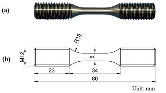
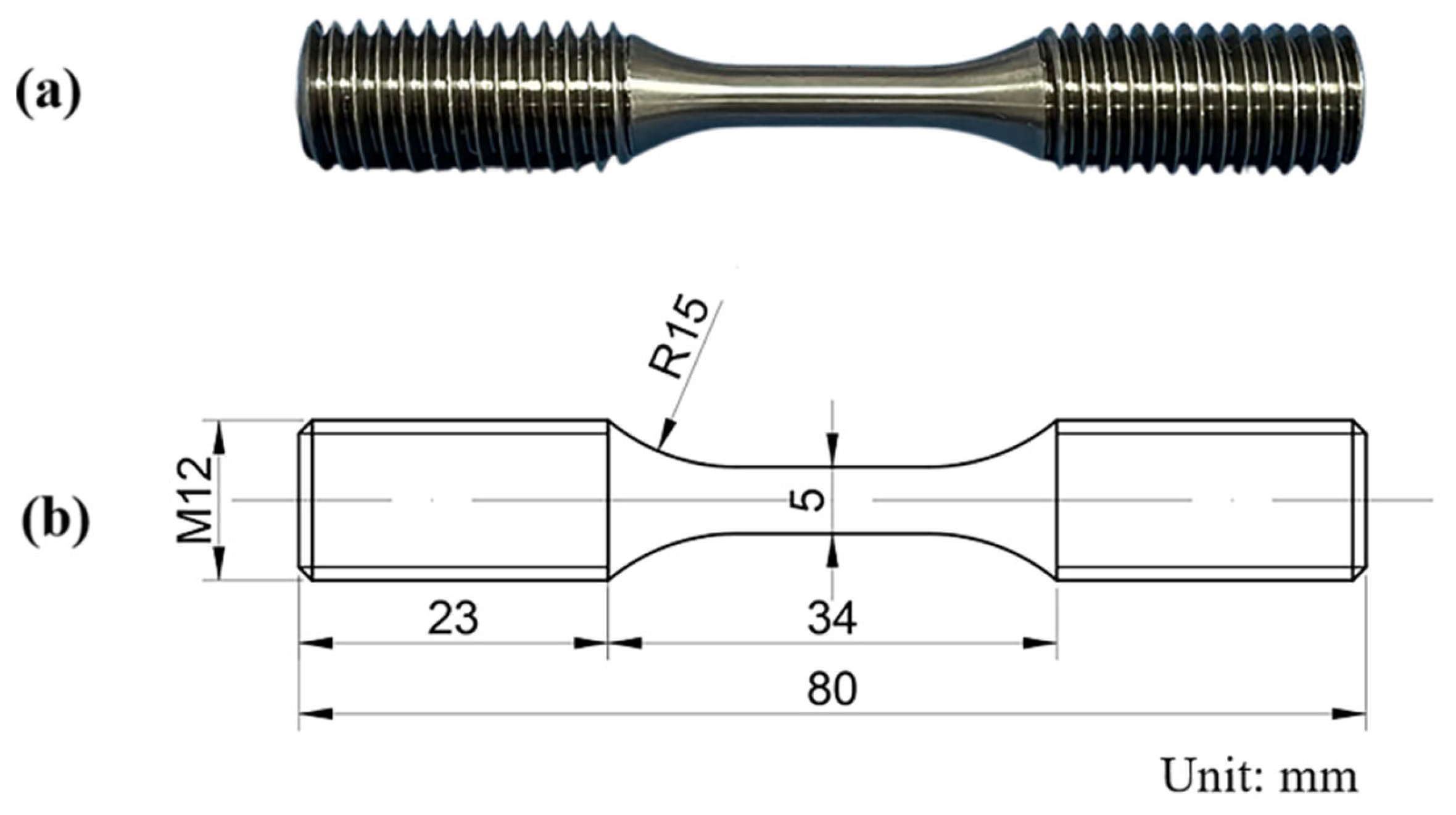
Cylindrical LCF specimens with a gauge diameter of 5 mm were CNC-machined using a C400K CNC machine from the heat-treated NiAlRe and NiAlReRu model superalloy bars, and the specimen geometry is shown in Figure 1. Fully reversed strain-controlled fatigue tests (R = −1) were performed on an MTS 370.10 servo-hydraulic testing system at 1000 °C with strain amplitudes of 0.2%, 0.4%, and 0.6%. The axial strain over the gauge length was measured using a high-temperature axial extensometer and used as the feedback signal for closed-loop strain control. A triangular waveform was applied at a constant strain rate of 4.8 × 10⁻³ s−1, corresponding to loading frequencies of 0.6, 0.3, and 0.2 Hz for strain amplitudes of 0.2%, 0.4%, and 0.6%, respectively. The detailed LCF testing parameters are summarized in Table 3.
Figure 1.
Schematic diagram of the specimen for LCF testing, illustrating the physical specimen (a) and dimensional drawing (b).
Table 3.
LCF experimental conditions.
Following the completion of experiments, a VHX-7000 Super-Depth-of-Field Microscope (SDM) (Keyence Corporation, Osaka, Japan) and SEM (Hitachi SU-70 and Sigma500 (ZEISS, Oberkochen, Germany)) were employed to observe the macro- and micro-scale fatigue fracture of specimens. Additionally, TEM (Tecnai G2 F20 S-TWIN and FEI Talos F200X, Thermo Fisher Scientific, Waltham, MA, USA) was utilized to investigate the dislocation configurations in both alloys after fatigue testing.
2.3. Computational Details
All the calculations were performed within the framework of DFT with the projector augmented plane-wave method, as implemented in the VASP [15]. The generalized gradient approximation proposed by Perdew, Burke, and Ernzerhof [16] screened hybrid density functional were selected for the exchange–correlation potential [17]. The van der Waals interaction was described by the DFT-D3 approach [18]. The plane-wave cutoff energy was set to 750 eV. The electronic self-consistent convergence criterion was set to 10−6 eV. Brillouin-zone integration was performed using a 2 × 2 × 1 k-point mesh. All structures were relaxed until the residual force on each atom was below 0.02 eV/Å.
3. Results and Discussion
3.1. Interfacial Re Segregation
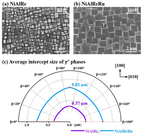
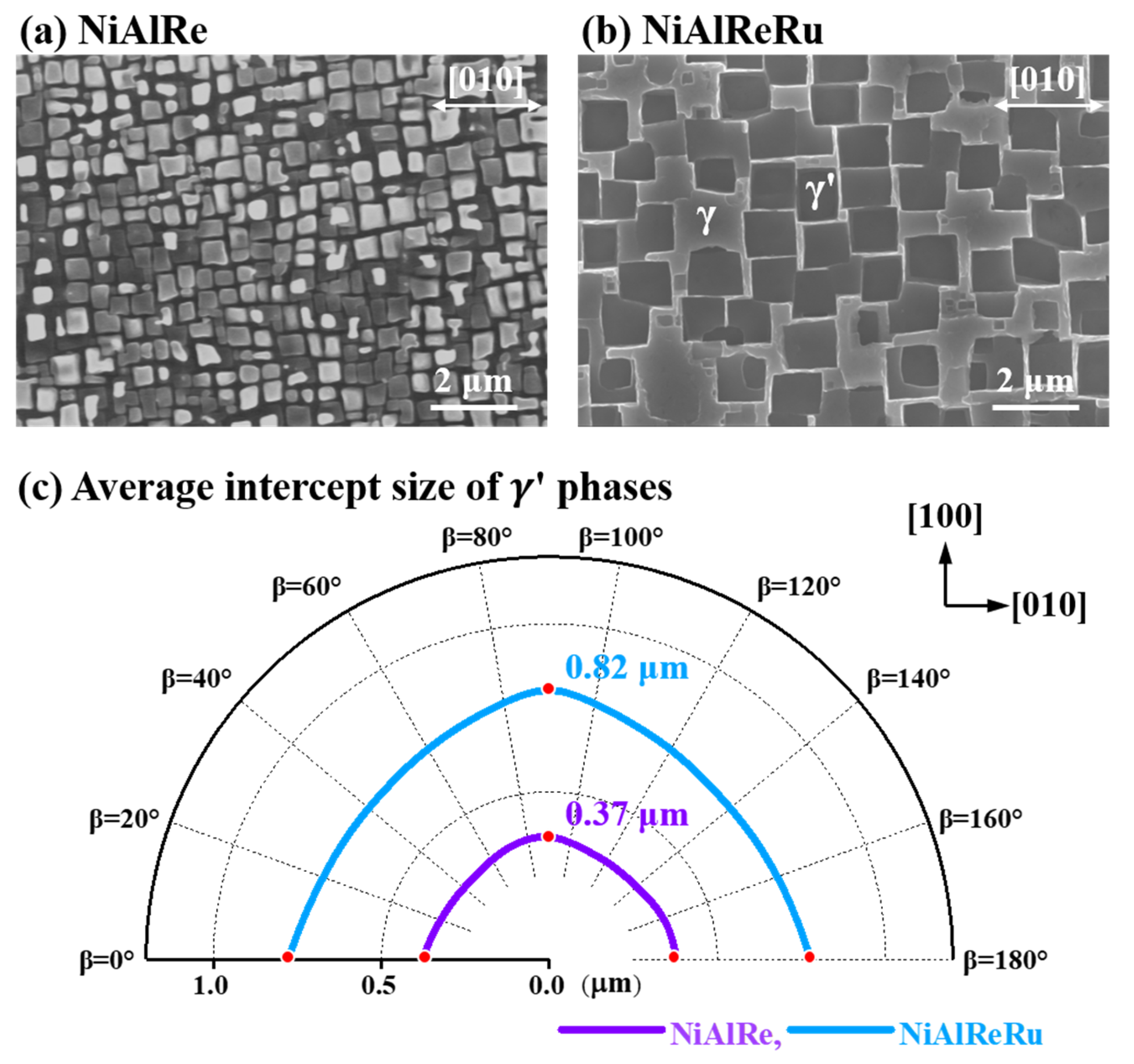
Figure 2a,b present SEM images of the dendritic stem regions on the (001) crystallographic plane for the heat-treated NiAlRe and NiAlReRu alloys, respectively. Figure 2c presents the MIPAR software analysis results of SEM images for both alloys. In the Rose diagrams, the radius represents the AIS of γ′ precipitates (units: μm), and the angular coordinate denotes the orientation of reference lines relative to the [010] direction. Both model alloys exhibit cuboidal γ′ precipitates, resulting in minimal AIS variations at β = 0°, 90°, and 180°, as indicated by the red points. Notably, the γ′ precipitates in NiAlReRu are larger: the AIS along the [100] direction (β = 90°) is 0.82 μm, compared with 0.37 μm for NiAlRe under identical heat-treatment conditions. Furthermore, the AIS profile of NiAlReRu exhibits greater symmetry about the β = 90° axis, indicating a more regular γ′ morphology. MIPAR analysis yielded γ′ area fractions of 63% and 68% for NiAlRe and NiAlReRu, respectively, indicating only a small difference between the two alloys.
Figure 2.
The microstructure of NiAlRe and NiAlReRu model superalloys after heat treatment. (a) SEM image of the dendritic stem region on the (001) crystallographic plane for the NiAlRe alloy. (b) SEM image of the same region for the NiAlReRu alloy. (c) MIPAR software analysis results showing the average intercept size (AIS) of γ′ precipitates for both alloys.
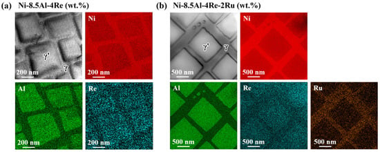
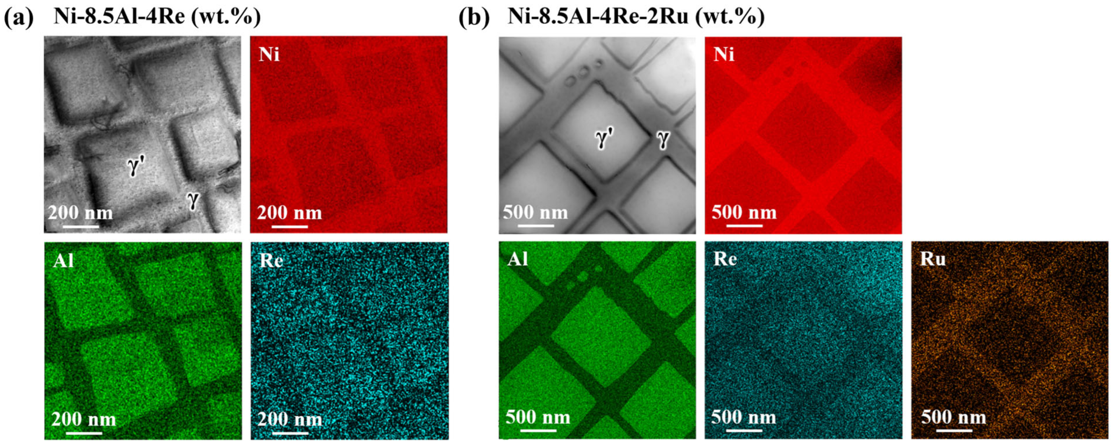
Figure 3 illustrates the elemental distribution in the heat-treated NiAlRe and NiAlReRu model alloys. Ni and Ru elements are preferentially distributed in the γ matrix, whereas Al and Re tend to partition into γ′ phases. Contrary to expectations, the distribution of Re in both model alloys differs from that in commercial Ni-based SXs. Commercial SXs typically contain over a dozen elements, and under the complex interactions among these elements, Re is inclined to segregate in the γ phase [4]. However, in the compositionally simplified model alloys investigated in this study, Re tends to partition into the γ′ phase [10]. The observed Re distribution can be understood from three aspects: (1) Thermodynamics: When a Re atom occupies an Al site in Ni3Al (γ′), the system’s binding energy decreases by 2.55 eV, which is significantly greater than the 0.68 eV reduction when occupying a Ni site [19]. (2) Atomic size: The atomic radius of Re (1.37 Å) closely matches that of Al (1.43 Å) but differs substantially from Ni (1.24 Å). Consequently, Re occupying Al sites in the Ni3Al lattice induces minimal local lattice distortion [19]. (3) Diffusion kinetics: The sluggish diffusion of Re may contribute to the persistence of a heterogeneous Re distribution across the γ/γ′ microstructure. Using the Arrhenius parameters reported by Epishin et al. [20] for Ni-rich FCC Ni–Re alloys, the Re interdiffusion coefficient at 1050 °C is estimated to be approximately 3.6 × 10⁻¹⁷ m2 s−1.
Figure 3.
Elemental distributions in the heat-treated Ni-8.5Al-4Re and Ni-8.5Al-4Re-2Ru (wt.%) model superalloys. (a) TEM image and corresponding Ni, Al, and Re elemental maps of NiAlRe. (b) TEM image and corresponding Ni, Al, Re, and Ru elemental maps of NiAlReRu.
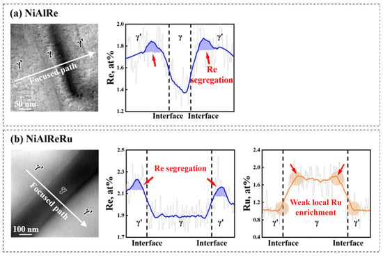
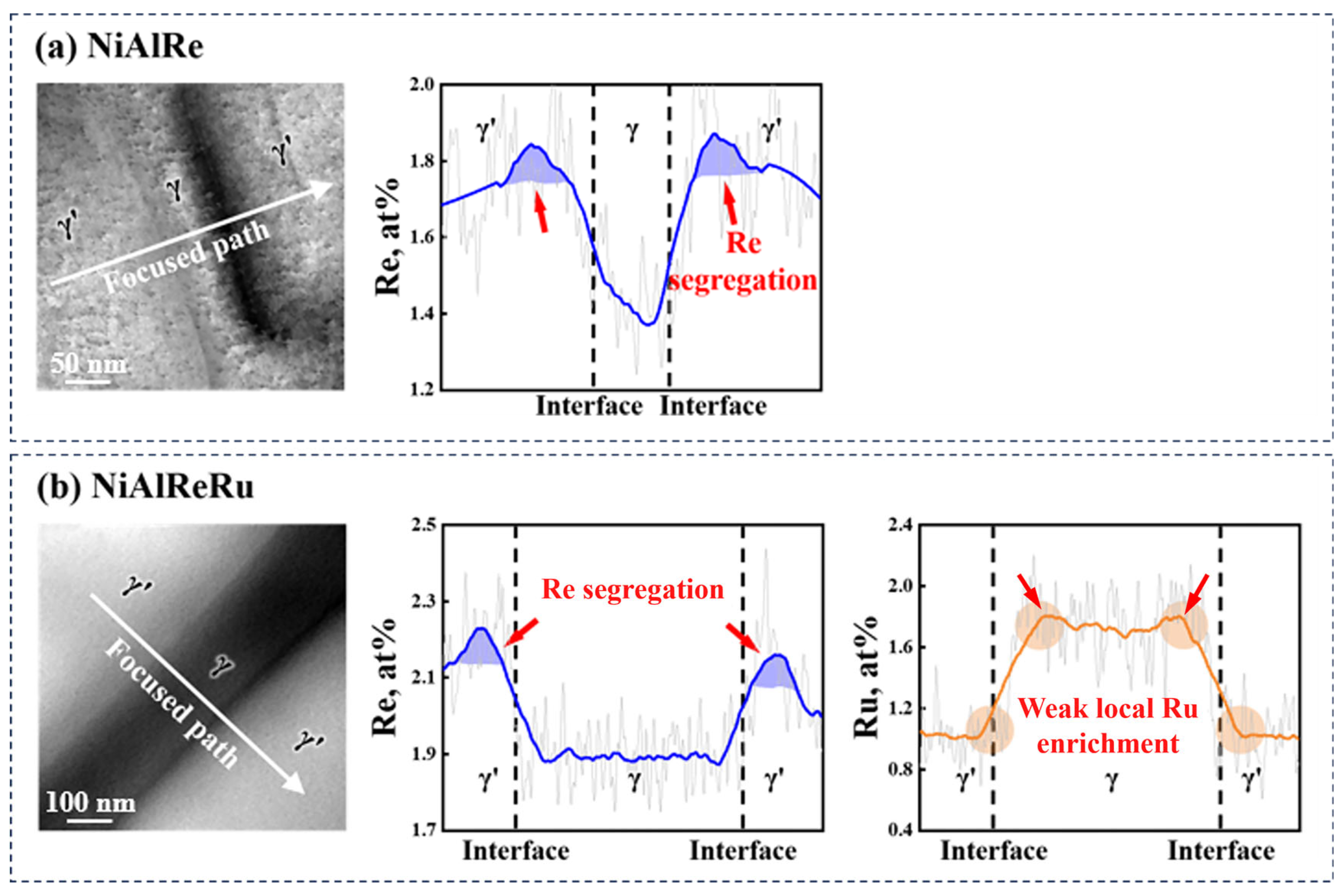
Figure 4 presents higher-magnification elemental line-scan for the NiAlRe and NiAlReRu alloys, showing schematic diagrams of the focused paths and the corresponding Re/Ru atomic percentage profiles along these paths. The Re distribution exhibits a characteristic uphill diffusion behavior away from the γ′ precipitates, forming a Re segregation layer near the γ/γ′ interface within the γ′ phase. This uphill diffusion feature is synergistically driven by chemical potential gradients and cross-diffusion effects [21]. Based on the concentration profiles shown in Figure 4, the Re concentration in the NiAlRe alloy reaches approximately 1.87 at.% near the γ′ side of the interface and decreases to approximately 1.37 at.% in the adjacent γ matrix, corresponding to an interfacial concentration difference of approximately 0.50 at.%. In the NiAlReRu alloy, the corresponding maximum and minimum Re concentrations are approximately 2.23 at.% and 1.90 at.%, respectively, giving a concentration difference of approximately 0.33 at.%. Although the precipitate size and matrix channel width in NiAlReRu are 2~3 times larger than those in NiAlRe (Figure 2), the Re segregation layer widths at the (001) γ′/γ interfaces are comparable (~55 nm) in both alloys. This geometrical difference means that the Re-enriched layer occupies a larger relative fraction of the smaller γ′ precipitates in NiAlRe and may contribute to the less uniform Re distribution between the γ′ and γ phases compared with NiAlReRu. The elemental distribution profiles in Figure 4b show distinct distribution characteristics of Ru and Re. Ru remains preferentially partitioned to the γ matrix, while a weak local Ru enrichment is observed near the γ′/γ interfaces relative to the adjacent γ matrix. This local Ru enrichment is less pronounced than the corresponding Re enrichment.
Figure 4.
The Re/Ru element distribution of NiAlRe and NiAlReRu model superalloys. (a) Re element line-scanning results at the γ′/γ interface of the NiAlRe alloy. (b) Re and Ru element line-scanning results at the γ′/γ interface of the NiAlReRu alloy. The dashed lines labeled ‘Interface’ indicate the approximate positions of the γ′/γ phase boundaries along the line-scan paths.
In both NiAlRe and NiAlReRu model superalloys, Re exhibits segregation at the γ′/γ interface. Such sluggish diffusion may limit Re redistribution during subsequent cooling and aging, particularly during γ′ precipitation and γ′/γ interface migration. Consequently, local Re enrichment may develop near the migrating γ′/γ interfaces, contributing to the formation of the observed segregation layer [22]. Computational studies [22,23,24,25] corroborate the presence of such segregation, revealing that Re segregation at the interface stabilizes the γ/γ′ boundary by reducing interfacial energy.
To quantitatively characterize the interfacial segregation of Re in both model alloys, the parameter was introduced. is a thermodynamic quantity commonly used to quantify interfacial segregation in multicomponent systems [26,27,28]. It represents the Gibbsian interfacial excess (GIE) calculated from measured local compositions and serves as a descriptor for the segregation intensity of element . The calculation formula for is presented as follows:
where is the known atomic density, represents the distance between adjacent concentration data points. In the γ′/γ interface, on the matrix side and on the precipitate side. References [29,30] have discussed using similar methods to determine the one-dimensional concentration excess across interfaces (grain boundaries) in such systems.
Additionally, the element partition coefficient (), a physical quantity describing elemental distribution between two phases, is typically calculated based on concentrations using the formula:
Here, is the concentration of element in the phase, and represents its concentration in the phase. The ratio greater than 1 indicates that element is enriched in the phase, whereas the value below 1 indicates preferential partitioning to the phase. The element partition coefficient can be used to quantify elemental distribution between γ matrix and γ’ precipitates in nickel-based SXs. To characterize the interfacial fluctuation magnitude of Re element, this study rewrites Equation (2) as
Here, is the maximum concentration of Re in the γ’ phase near the γ’/γ interface, and is the minimum concentration of Re in the γ phase near the γ’/γ interface. The modified represents the maximum Re concentration ratio within the interfacial analysis region (defined as ±100 nm), thus quantitatively reflecting the fluctuation magnitude of Re distribution across the interface. The ±100 nm region is used as an analysis window for quantitative comparison and does not represent the physical thickness of the γ′/γ interface. The Gibbsian interfacial excess of Re, , is expressed in atom nm−2 because it represents the atomic excess of Re per unit interfacial area, whereas is a dimensionless parameter characterizing the relative magnitude of Re concentration fluctuation within the interfacial region.
The results calculated using Equations (1) and (3) are summarized in Table 4. Although Re segregation is observed near the γ′/γ interface in both alloys, the segregation intensity differs considerably between the two alloys. For the NiAlRe alloy, the Gibbsian interfacial excess of Re () is 18.19 ± 1.75 atom nm−2, and the maximum interfacial Re concentration ratio () is 1.36 ± 0.01. For the NiAlReRu alloy containing 2 wt.% Ru, decreases to 11.42 ± 0.01 atom nm−2, corresponding to a reduction of approximately 37%, while decreases to 1.17 ± 0.02. These results indicate that the interfacial enrichment and concentration fluctuation of Re are more pronounced in NiAlRe, whereas NiAlReRu exhibits a more uniform Re distribution across the γ′/γ interfacial region. Thus, the addition of Ru is associated with reduced interfacial Re segregation and concentration fluctuation. The difference in interfacial Re fluctuation is also consistent with the DFT-calculated segregation energies discussed in Section 3.3.1, which indicate a stronger thermodynamic preference for Re interfacial segregation in the Re-only system than in the Re + Ru system.
Table 4.
Quantitative parameters characterizing Re segregation at the γ′/γ interface.
3.2. LCF Performance Comparison
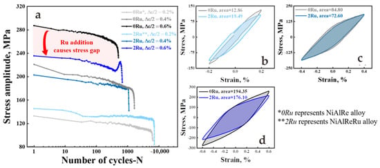
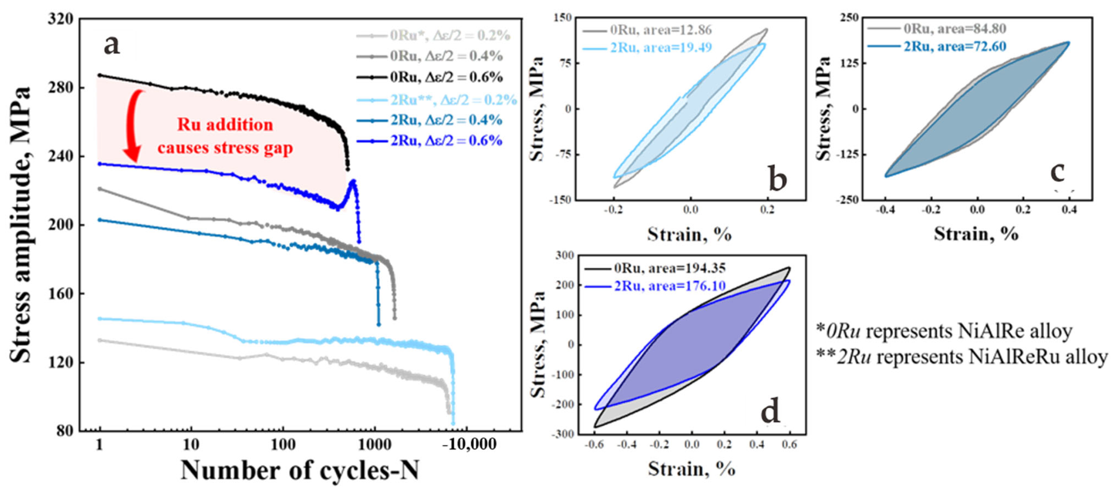
The LCF cyclic stress response curves of NiAlRe and NiAlReRu alloys at 1000 °C are shown in Figure 5a. The two alloys exhibit comparable fatigue lives at the investigated strain amplitudes, and the fatigue life of both alloys decreases with increasing strain amplitude. The difference in fatigue life between NiAlRe and NiAlReRu varies with strain amplitude, suggesting that the fatigue-life difference is not governed solely by the cyclic stress amplitude. Local microstructural heterogeneity and subsequent fatigue-damage evolution may also influence the fatigue life, as discussed below. Before the final stress drop, the cyclic stress amplitude reflects the resistance to cyclic deformation of the alloys under strain-controlled loading. At a strain amplitude of 0.2%, the NiAlReRu alloy exhibits a slightly higher cyclic stress response than NiAlRe. In contrast, at strain amplitudes of 0.4% and 0.6%, NiAlRe exhibits higher stress amplitudes, with the difference becoming more pronounced at 0.6%. The higher cyclic stress response of NiAlRe at the higher strain amplitudes indicates a greater resistance to cyclic deformation. This behavior is consistent with its more pronounced interfacial Re enrichment and the DFT result that the increase in unstable stacking-fault energy is larger in the Re-only system than in the Re + Ru system. This interpretation is further supported by the different post-fatigue dislocation configurations observed at 0.6% strain amplitude, as discussed below.
Figure 5.
The high-temperature LCF performance of NiAlRe and NiAlReRu alloys. (a) The stress response curve in various strain amplitudes. (b) The half-life hysteresis loops in 0.2% strain amplitude. (c) The half-life hysteresis loops in 0.4% strain amplitude. (d) The half-life hysteresis loops in 0.6% strain amplitude.
Generally, the cyclic hysteresis curve of the material reflects the accumulation process of plastic strain energy in LCF cycles [31,32], where each hysteresis loop corresponds to one fatigue damage accumulation, as shown in Figure 5b–d. The half-life hysteresis loops at strain amplitudes of 0.4% and 0.6% also demonstrate that lower stress already achieves the same strain level in the Ru-containing alloy. At the low strain amplitude of 0.2%, the elastic strain dominates, leading to no obvious stress difference between the two alloys [33]. At the same temperature, as the strain amplitude increases, the width of the half-life hysteresis loops expands, indicating a greater contribution of plastic strain to fatigue life and fatigue damage enhanced. Additionally, during cyclic loading, the peak tensile and compressive stresses of the specimens exhibit strong symmetry, and the hysteresis loops display well-defined closed shapes. This suggests that both alloys lack significant tension–compression asymmetry.
3.2.1. Microstructure Analysis
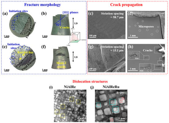
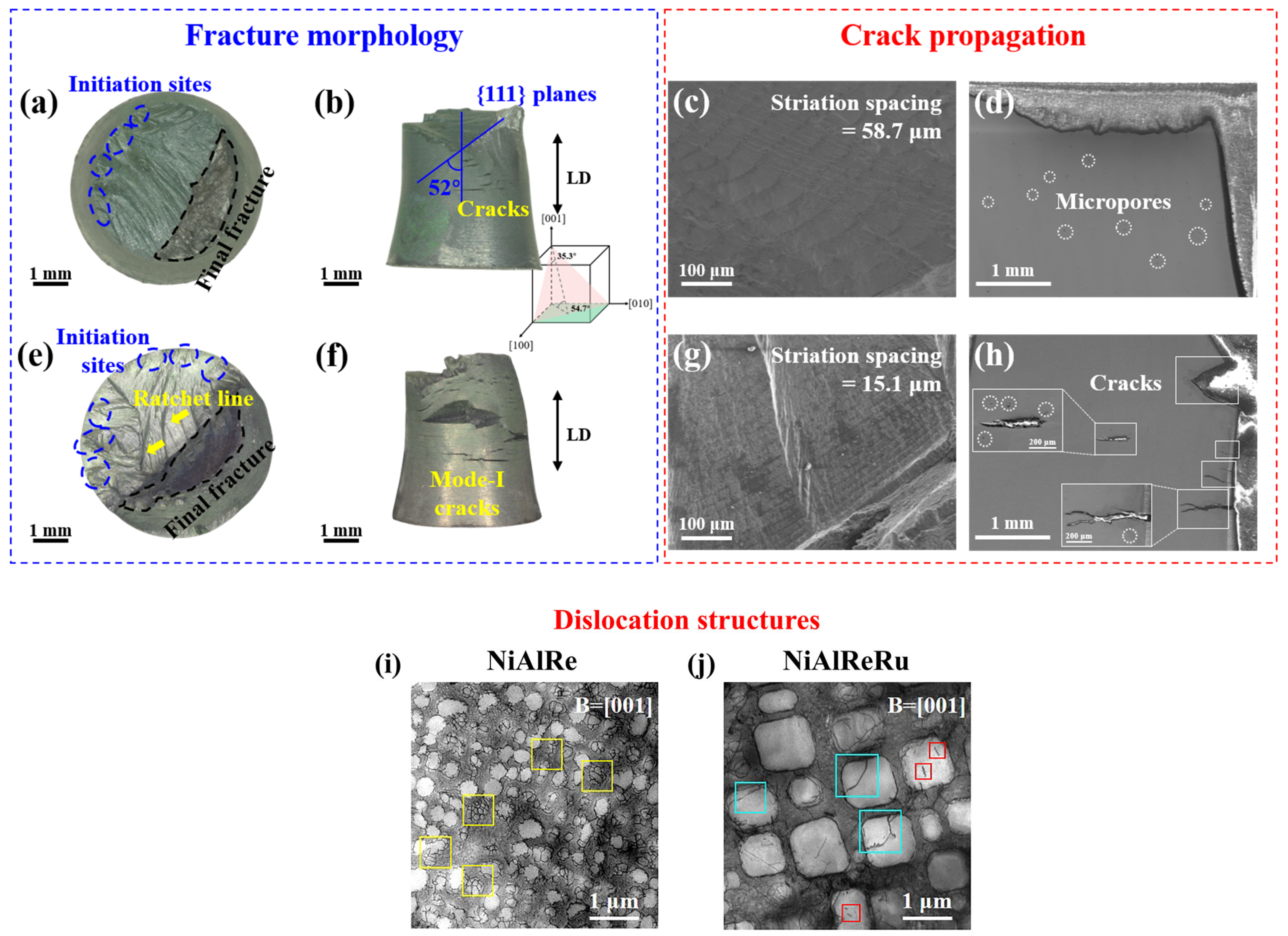
Further analysis was conducted on the specimens tested at the highest strain amplitude of 0.6%, where the difference in stress response between the two alloys was most pronounced. Figure 6 summarizes the fracture morphologies, crack propagation features, and dislocation configurations of the NiAlRe and NiAlReRu specimens after low-cycle fatigue deformation at 1000 °C. As shown in Figure 6a,e, the fatigue fracture process can be divided into three typical stages, namely crack initiation, stable crack propagation, and final rupture. Both alloys exhibit fatigue striations and river-like patterns in the crack propagation regions, indicating typical low-cycle fatigue fracture characteristics [34,35]. Compared with the NiAlRe specimen, the NiAlReRu specimen shows more dispersed crack initiation sites, as marked by the blue dashed circles in Figure 6a,e. Cracks initiated from different locations coalesce during subsequent propagation, resulting in the formation of ratchet lines. Therefore, the NiAlRe specimen exhibits a relatively flat fracture surface and a more stable crack propagation path, whereas the NiAlReRu specimen shows more pronounced ratchet lines and a more uneven fracture morphology, suggesting that Ru addition promotes multiple-site crack initiation under cyclic loading.
Figure 6.
Fatigue fracture morphologies and dislocation structures of NiAlRe and NiAlReRu alloys at 1000 °C under a strain amplitude of 0.6%. (a–d,i) NiAlRe; (e–h,j) NiAlReRu. (a,e) Fracture surfaces; (b,f) side-view cracks; (c,g) fatigue striations; (d,h) longitudinal crack profiles; and (i,j) dislocation structures.
The side-view morphologies further reveal the crystallographic nature of fatigue cracking. As shown in Figure 6b, the fracture surface of the NiAlRe specimen mainly consists of two intersecting crystallographic planes. The measured angle between the fracture plane and the loading direction is approximately 52°, which is close to the theoretical angle of 54.7° between the {111} slip plane and the loading axis. This result indicates that fatigue deformation is mainly governed by octahedral slip. Since the present single-crystal alloys possess an FCC-based γ/γ′ microstructure, activation of the {111} <110> slip system is expected to be one of the dominant deformation modes during high-temperature fatigue. Surface cracks perpendicular to the loading direction are observed in both specimens, as shown in Figure 6b,f. However, the NiAlReRu specimen contains longer and more numerous mode-I cracks, indicating a higher tendency for surface crack formation and propagation.
The microscopic crack propagation features are shown in Figure 6c,g. Fatigue striations are observed in both alloys, confirming cyclic crack advance during fatigue loading. The average striation spacing is approximately 58.7 μm in the NiAlRe specimen and 15.1 μm in the NiAlReRu specimen. Fatigue-striation spacing is related to the local crack-propagation condition and can be influenced by factors such as the local crack-tip driving force and crack-closure behavior [36]. In the present study, the NiAlReRu specimen exhibits multiple crack-initiation sites, secondary cracks, and more pronounced crack coalescence, which may modify the local crack-propagation conditions and thereby contribute to the smaller striation spacing.
Longitudinal sections parallel to the loading direction are presented in Figure 6d,h. In the NiAlRe specimen, no obvious long cracks are detected in the observed region, although oval-shaped micropores are present. In contrast, the NiAlReRu specimen exhibits edge cracks perpendicular to the loading direction, internal cracks, and secondary cracks near the main crack tip. Some cracks are spatially associated with micropores, suggesting that micropores may act as local stress-concentration sites and facilitate crack initiation during cyclic loading. In addition, oxide penetration is observed at some crack tips, which may further promote local crack opening and propagation at 1000 °C.
The dislocation structures after fatigue deformation are shown in Figure 6i,j. In the NiAlRe specimen, the γ′ precipitates exhibit rounded corners and partial interconnection after cyclic loading. Dislocations are mainly distributed along the γ/γ′ interfaces, where they form interfacial dislocation networks. Such networks can generate long-range elastic stress fields and effectively hinder further dislocation motion and cutting into the γ′ phase [37,38], thereby contributing to cyclic hardening and fatigue resistance.
By contrast, the NiAlReRu specimen exhibits a less uniform post-fatigue dislocation distribution around the γ′/γ interfaces and γ channels. Together with the more dispersed crack-initiation sites, secondary cracks, and more pronounced crack coalescence observed in NiAlReRu, these features indicate more severe fatigue damage in the NiAlReRu alloy at a strain amplitude of 0.6%.
In comparison, the NiAlReRu specimen also exhibited reduced cuboidal regularity of the γ′ phase. However, unlike the NiAlRe alloy, its γ matrix contained a high density of entangled dislocations, and dislocations cut into most γ′ precipitates. As the γ′ phase possesses an L12-ordered structure, dislocations are typically absent prior to deformation. Post-deformation, dislocations within the γ′ phase primarily originate from the γ matrix. The extensive number of dislocations into the γ′ phase induces significant degradation of alloy properties [39,40,41,42,43,44]. As shown in Figure 6j, dislocations cutting into γ′ precipitates primarily manifest as two types: long dislocations (marked by blue boxes) and dislocation pairs (marked by red boxes). The long dislocations correspond to a <010> superdislocations, exhibiting morphologies such as straight lines [43], zigzag patterns [41,45], or arched configurations [46], predominantly extending along <110> or <110> directions. These form when two a/2<110> dislocations with distinct Burgers vectors combine within the γ matrix before cutting into the γ′ phase. The dislocation pairs represent a <101> superdislocations, commonly observed in γ′ phases under intermediate-to-high temperature conditions. These consist of two parallel dislocations extending along [100] directions, appearing as short meandering segments. The mechanism involves: When a single a/2<110> dislocation cut into γ′ phase, it disrupts the atomic ordering, increasing the system energy. To minimize this energy, a second dislocation enter the γ′ phase to restore atomic alignment. Consequently, a<101> superdislocations typically exist as paired configurations, sharing the same {111} slip plane and Burgers vector. The region between the paired dislocations forms a high-energy interface, which is called antiphase boundary (APB), a planar defect arising from atomic misalignment. Given the inherently high APB energy in γ′ phases [47], the spacing between the two a/2<101> dislocations remain relatively narrow.
3.2.2. Hysteretic Energy Model
The hysteresis energy model is applicable to various metallic materials and demonstrates particular advantages in predicting LCF life, especially under high-temperature conditions. In this study, the hysteresis energy model is employed to compare the intrinsic mechanisms of fatigue damage in the two alloys. Based on hysteresis loops, the model interprets fatigue damage as an energy accumulation process, defining the damage parameter as
where represents the hysteresis energy during the cycle, denotes the intrinsic fatigue toughness, and is the damage transition exponent. Both and are material-specific constants. As the number of cycles increases and fatigue damage accumulates, material fracture occurs when the total damage ; thus [48],
After simplification:
where is the saturation hysteresis energy. Compared to the classical Coffin-Manson model, the hysteresis energy model provides a more accurate description of the integrated fatigue behavior exhibited by materials during cyclic loading, thereby elucidating the intrinsic mechanisms of fatigue damage. However, since the model approximates hysteresis energy across varying cycles using saturated hysteresis energy during its simplification process, its accuracy may diminish when applied to alloys with poor cyclic stability. To quantify the dispersion discrepancies in model calculations, the life prediction factor (LPF) [48] is adopted to evaluate the accuracy of the model:
where is the predicted fatigue life value, and is the experimental fatigue life value.
Based on the above calculations, the hysteresis energy model parameters for NiAlRe and NiAlReRu alloys are listed in Table 5. The LPF values are 1.45 and 1.10 for NiAlRe and NiAlReRu, respectively, indicating closer agreement between the predicted and experimental fatigue lives for NiAlReRu. The difference in LPF may arise from the use of the saturation hysteresis energy to approximate the cycle-dependent evolution of hysteresis energy. Because the two alloys exhibit different cyclic stress and hysteresis responses, this approximation can lead to different levels of prediction error. The NiAlRe specimen exhibits a lower damage transition exponent () and a higher intrinsic fatigue toughness (), indicating superior energy dissipation capacity and damage resistance under cyclic loading. Compared to the NiAlReRu alloy, these characteristics enable the NiAlRe alloy to exhibit enhanced fatigue performance. Specifically, the lower implies that the NiAlRe alloy inefficiently converts plastic work into fatigue damage under identical cycle counts, thereby delaying damage accumulation. The higher signifies that the NiAlRe alloy can endure more loading cycles under equivalent cyclic plastic work, reflecting its superior fatigue resistance. This enhanced toughness enables the NiAlRe alloy to more effectively disperse energy during fatigue loading, suppressing crack initiation and propagation. These model-derived conclusions align well with the experimental observations discussed in this section.
Table 5.
The parameters of hysteresis energy model.
Based on all the experimental observations above, it can be found that the Re-Ru interaction mechanism in the model alloy system focused in this paper supports Viewpoint (1) presented in Section 1, that is, Ru exerts a reverse partitioning effect on Re elements. However, distinct elemental compositions induce different Re distributions across SXs, resulting in varied impacts from the Ru’s reverse partitioning effect. In most commercial alloys, Re exhibits reduced supersaturation in the γ matrix under the Ru’s reverse partitioning effect [49,50]. This leads to suppressed precipitation of TCP phases and consequently enhances the alloy’s performance [51,52,53,54]. However, in the model alloys discussed in this work, characterized by limited refractory elements and the absence of TCP-phase formation, Ru addition reduces Re segregation at the γ′/γ interface, which may contribute to the observed differences in cyclic deformation behavior between the two alloys. This underscores that elemental effects cannot be considered in isolation, as the complex synergistic interactions among elements collectively govern microstructural evolution and performance optimization in superalloys.
3.3. DFT Calculations
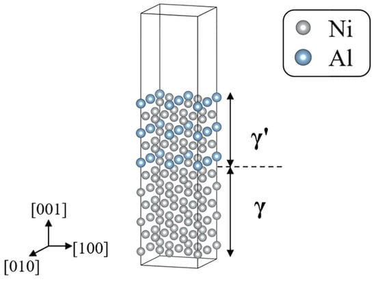
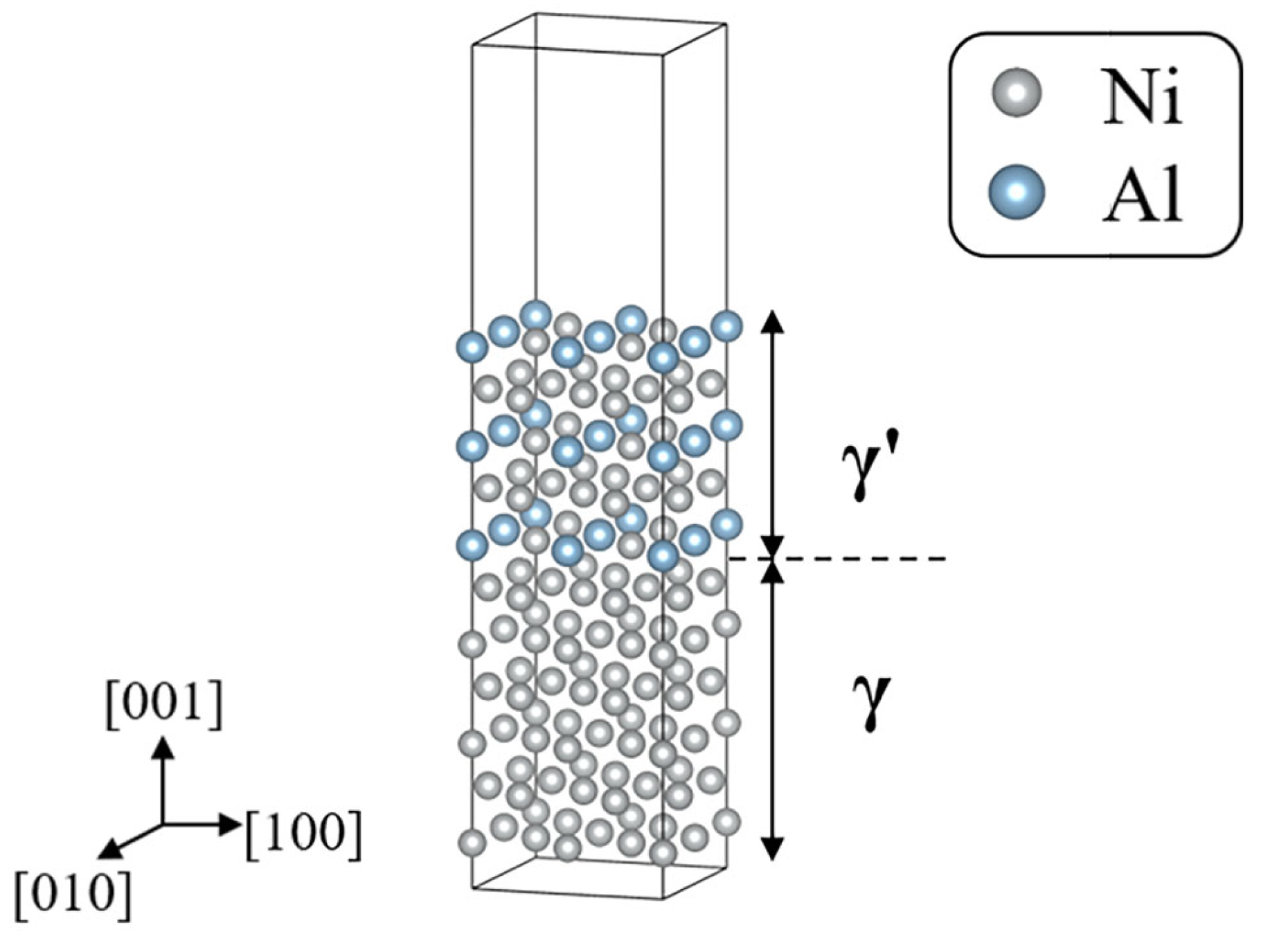
This section applies DFT calculations to establish fundamental correlations between the observed experimental phenomena and their atomic/electronic structure. Ignoring small lattice misfit and assuming completely coherency between γ (Ni) and γ′ (Ni3Al) phases [55,56,57], a supercell model is established as shown in Figure 7. The initial structure of the γ′/γ interface model consists of 6 atomic layers of Ni and 5 atomic layers of Ni3Al.
Figure 7.
Ni/Ni3Al phase interface model.
3.3.1. Re Segregation Energy
To quantitatively evaluate the thermodynamic propensity of Re atoms to segregate at γ′/γ interfaces, the segregation energy (Eseg) is introduced as the criterion. Eseg is defined as the energy difference between an element at an interface and the same element located in the bulk phase of the material. This physical quantity directly reflects the affinity disparity between the interface and bulk for the specific element [58]. A negative value indicates that the atom attains a lower-energy state at the interface, exhibiting a thermodynamic driving force for spontaneous segregation toward the interface. Conversely, a positive value signifies an energy-driven repulsion of the element from the interfacial region. The mathematical expression is formulated as
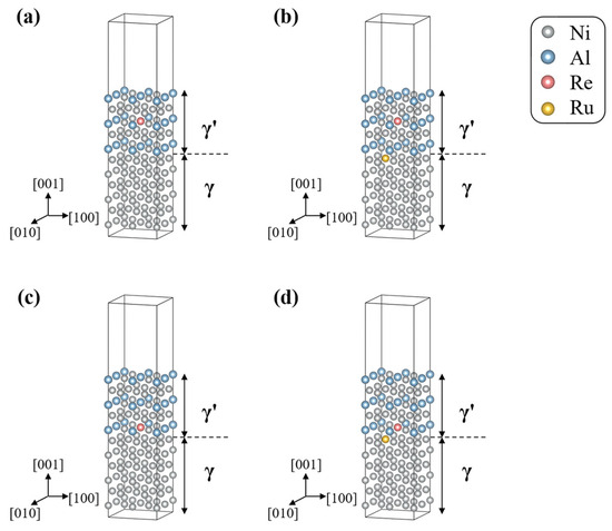
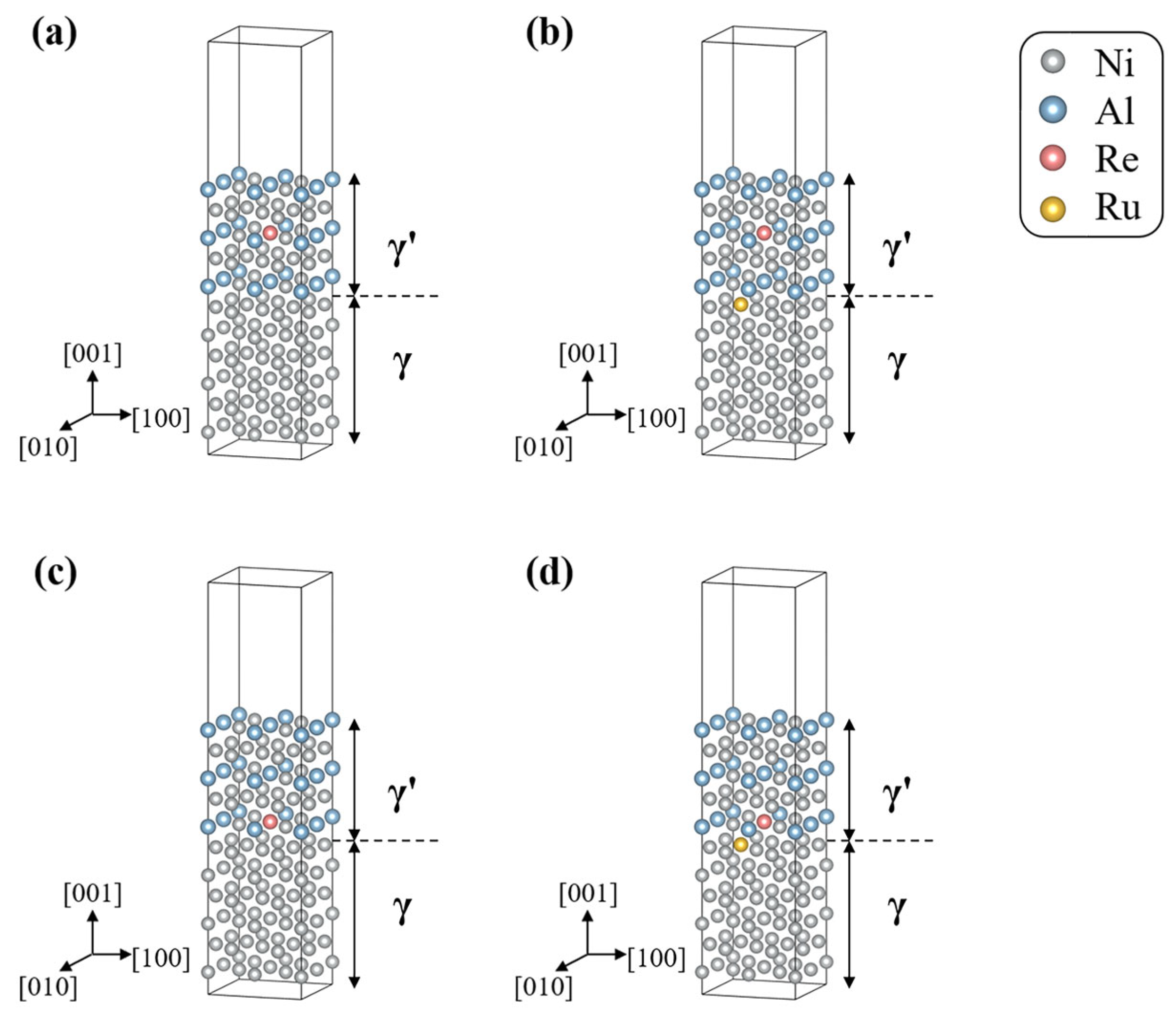
The atomic configurations used to calculate the Re segregation energy are illustrated in Figure 8. Figure 8a,b represent the reference configurations with Re located within the γ′ phase, without and with Ru, respectively, whereas Figure 8c,d represents the corresponding configurations with Re located at the γ′/γ interface. The Re segregation energy is determined by comparing the energies of the interfacial and γ′ reference configurations according to Equation (8). The doping site for the Ru atom was selected based on the most thermodynamically favorable location, corresponding to the most negative doping energy (−4.19 eV) calculated for the system. The calculated segregation energy of Re is −0.200 eV, indicating that the interfacial configuration is energetically preferred over the γ′ reference configuration. Upon the introduction of Ru, the segregation energy increases to −0.166 eV, indicating a reduced thermodynamic tendency for Re segregation at the γ′/γ interface. Furthermore, the segregation energy of Ru—defined as the energy difference between the interface and the γ matrix—is calculated to be 0.14 eV, indicating that, in the present model, the γ′/γ interface is not energetically favored over the γ matrix as a segregation site for Ru.
Figure 8.
Atomic configurations used for Re segregation energy calculations. (a) Re located within the γ′ phase; (b) Re located within the γ′ phase with Ru co-doping; (c) Re located at the γ′/γ interface; and (d) Re located at the γ′/γ interface with Ru co-doping.
The experimentally observed Re enrichment at the γ′/γ interface can be understood from both thermodynamic and kinetic considerations. Thermodynamically, the negative segregation energy calculated in the present study indicates that, in the present model, Re is energetically more favorable at the γ′/γ interface than at the selected reference site within the γ′ phase, providing a thermodynamic driving force for interfacial segregation. This interpretation is consistent with previous first-principles calculations showing that Re segregation can enhance the thermodynamic stability of the γ′/γ interface [22]. Kinetically, the sluggish diffusion of Re limits its redistribution during γ′ evolution and γ′/γ interface migration [23]. As the interface evolves, the limited mobility of Re prevents rapid homogenization of the local Re distribution, allowing local concentration gradients to be retained near the moving interface. The combined thermodynamic preference for the interface and kinetically limited redistribution therefore contribute to the experimentally observed Re enrichment at the γ′/γ interface.
3.3.2. Generalized Stacking Fault Energy
To investigate the effect of Re and Ru to impede dislocation motion in the Ni/Ni3Al interface system, this subsection calculates the before and after alloying. The at each step () was computed using Equation (9) [59,60]:
where and are respectively the energies of the undisplaced and displaced by a step cells, and is the area of the cell in the sliding planes.
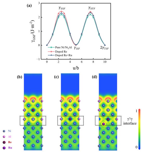
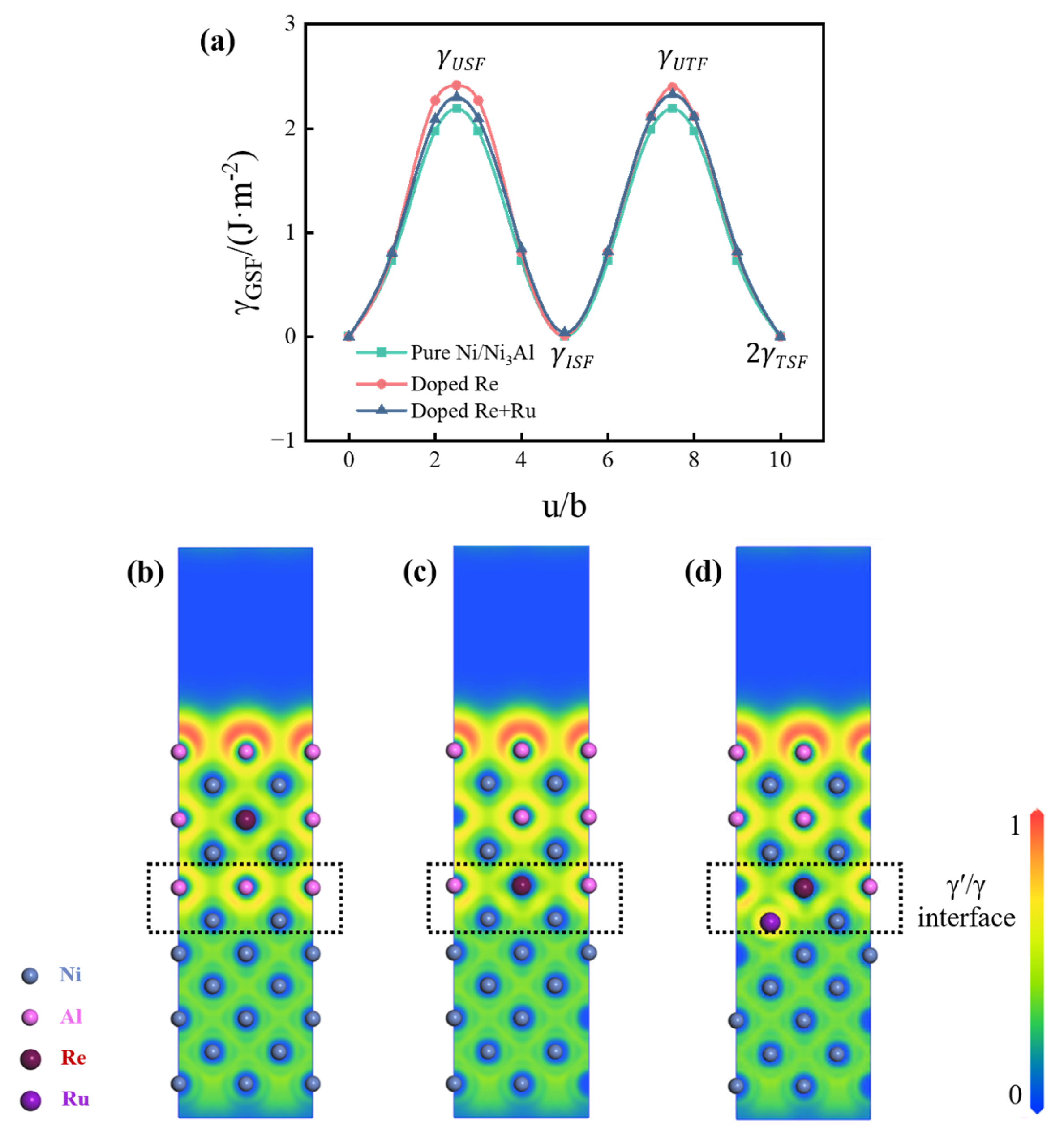
Figure 9a shows the variation of with the slip vector for the γ′/γ interface cell before and after alloying under the {001} <110> slip system. The first energy peak in the curve corresponds to the unstable stacking fault energy (), which represents the energy barrier required for the material to form partial dislocations under external stress. A higher indicates greater difficulty in the nucleation or glide of dislocations. Single doping with Re atoms, the increased by 10.34% compared to the unalloyed system, while when Re and Ru were co-doped, the increase in was only 5.05%. This result indicates that Re doping enhances the resistance to slip system activation, but the synergistic introduction of Ru can partially counteract the inhibitory effect of Re on dislocation motion at the γ′/γ interface.
Figure 9.
Variation of and ELF distributions of pure and alloyed γ′/γ interfaces. (a) variation with displacement u in the {001} <110> slip system. (b–d) ELF maps under different doping conditions: (b) Re in the γ′ phase, (c) Re at the γ′/γ interface, and (d) Re at the γ′/γ interface with Ru co-doping.
Figure 9b–d presents the electron localization function (ELF) distributions under different doping conditions. Re located within the γ′ phase has little influence on the interfacial electron distribution, with electrons remaining predominantly localized around Al atoms (Figure 9b). In contrast, when Re is located at the γ′/γ interface, charge redistribution and enhanced electron delocalization are observed in the interfacial region (Figure 9c). With Ru co-doping, part of the electron localization is restored (Figure 9d), indicating that Ru partially modifies the Re-induced change in the interfacial electronic structure. This trend is consistent with the generalized stacking-fault-energy results: Re alone increases the unstable stacking-fault energy by 10.34% relative to the unalloyed interface, whereas Re–Ru co-doping results in a smaller increase of 5.05%. Thus, Ru co-doping partially counteracts the Re-induced modification of the interfacial electronic structure and is accompanied by a smaller increase in the energy barrier for slip-system activation.
4. Conclusions
This study investigates the Re distribution and LCF behavior of NiAlRe and NiAlReRu model SXs through microstructural characterization and theoretical calculations, revealing the intrinsic relationship between elemental interactions, interfacial stability, and fatigue performance. The main conclusions are as follows:
(1) Re segregates at the γ′/γ interface in both model alloys, while the addition of 2 wt.% Ru reduces the interfacial segregation of Re. The Gibbsian interfacial excess of Re decreases from 18.19 ± 1.75 to 11.42 ± 0.01 atom nm−2 (≈37%), and the maximum interfacial Re concentration ratio decreases from 1.36 ± 0.01 to 1.17 ± 0.02.
(2) At a strain amplitude of 0.6%, the NiAlReRu alloy exhibits a lower cyclic stress response and more pronounced fatigue damage than NiAlRe. The reduced interfacial Re segregation in NiAlReRu is accompanied by a change in the post-fatigue dislocation configuration, with predominantly interfacial dislocation networks in NiAlRe but more extensive dislocation penetration into the γ′ precipitates in NiAlReRu. This change may contribute to the more severe fatigue damage observed in the Ru-containing alloy.
(3) DFT calculations show that Ru reduces the thermodynamic tendency for Re segregation at the γ′/γ interface, with the segregation energy increasing from −0.200 to −0.166 eV. Re raises the unstable stacking-fault energy by 10.34% relative to the unalloyed interface, whereas Re–Ru co-doping limits the increase to 5.05% and partially restores electron localization, indicating a lower resistance to dislocation slip than in the Re-only system.
(4) The effect of Re–Ru interactions is composition dependent. In commercial SXs, Ru can reduce Re enrichment in the γ matrix and suppress TCP-phase precipitation, whereas in the present model alloys, its principal effect is manifested as reduced Re segregation at the γ′/γ interface. This contrast highlights the strong dependence of Re–Ru interactions on the overall alloy chemistry.
In summary, this work clarifies the regulatory effect of Ru on Re distribution and its correlation with LCF performance, providing insight into elemental interaction mechanisms and composition optimization in Ni-based SX superalloys.
Author Contributions
Conceptualization, Y.S. and H.W.; methodology, Y.S. and K.L.; software, Y.S.; validation, K.L. and J.Z.; formal analysis, Y.S. and X.G.; investigation, Y.S. and B.L.; resources, H.W.; data curation, J.D., Y.S. and Y.P.; writing—original draft preparation, Y.S.; writing—review and editing, Y.S., K.L., J.Z., X.G., B.L., Y.P., W.W., J.D. and H.W. visualization, Y.S. and W.W.; supervision, H.W.; project administration, H.W.; funding acquisition, H.W. All authors have read and agreed to the published version of the manuscript.
Funding
This work was supported by the Excellent Research Groups Program for Multiphase Evolution in Hyper-gravity of the National Natural Science Foundation of China [grant number 52588202]; the National Natural Science Foundation of China [grant number 52173302]; and the Fundamental Research Funds for the Central Universities [grant number 226-2023-00119].
Data Availability Statement
The original contributions presented in this study are included in the article. Further inquiries can be directed to the corresponding author.
Conflicts of Interest
Author Youbei Sun was employed by the company Dongfang Electric Corporation Dongfang Turbine Co., Ltd., Deyang 618000, China, and the State Key Laboratory of Clean and Efficient Turbomachinery Power Equipment, Deyang 618000, China; Author Xiufang Gong was employed by the company Dongfang Electric Corporation Dongfang Turbine Co., Ltd., Deyang 618000, China, and the State Key Laboratory of Clean and Efficient Turbomachinery Power Equipment, Deyang 618000, China. Author Bin Long was employed by the company Dongfang Electric Corporation Dongfang Turbine Co., Ltd., Deyang 618000, China, and the State Key Laboratory of Clean and Efficient Turbomachinery Power Equipment, Deyang 618000, China. Author Yubing Pei was employed by the company Dongfang Electric Corporation Dongfang Turbine Co., Ltd., Deyang 618000, China, and the State Key Laboratory of Clean and Efficient Turbomachinery Power Equipment, Deyang 618000, China. Author Wei Wang was employed by the company Dongfang Electric Corporation Dongfang Turbine Co., Ltd., Deyang 618000, China, and the State Key Laboratory of Clean and Efficient Turbomachinery Power Equipment, Deyang 618000, China. Author Juanqiang Ding was employed by the company Dongfang Electric Corporation Dongfang Turbine Co., Ltd., Deyang 618000, China, and the State Key Laboratory of Clean and Efficient Turbomachinery Power Equipment, Deyang 618000, China. The remaining authors declare that the research was conducted in the absence of any commercial or financial rela-tionships that could be construed as a potential conflict of interest.
References
- Liu, L.R.; Jin, T.; Zhao, N.R.; Wang, Z.H.; Sun, X.F.; Guan, H.R.; Hu, Z.Q. Microstructural evolution of a single crystal nickel-base superalloy during thermal exposure. Mater. Lett. 2003, 57, 4540–4546. [Google Scholar] [CrossRef] [Scilit]
- Pollock, T.M.; Tin, S. Nickel-Based Superalloys for Advanced Turbine Engines: Chemistry, Microstructure and Properties. J. Propuls. Power 2006, 22, 361–374. [Google Scholar] [CrossRef] [Scilit]
- Gasson, P.C. The Superalloys: Fundamentals and Applications R. C. Reed Cambridge University Press, The Edinburgh Building, Shaftesbury Road, Cambridge, CB2 2RU, UK, 2006. 372pp. Illustrated. £80. ISBN 0-521-85904-2. Aeronaut. J. 2008, 112, 291. [Google Scholar] [CrossRef] [Scilit]
- Ding, Q.; Li, S.; Chen, L.-Q.; Han, X.; Zhang, Z.; Yu, Q.; Li, J. Re segregation at interfacial dislocation network in a nickel-based superalloy. Acta Mater. 2018, 154, 137–146. [Google Scholar] [CrossRef] [Scilit]
- Zhou, H.; Ro, Y.; Harada, H.; Aoki, Y.; Arai, M. Deformation microstructures after low-cycle fatigue in a fourth-generation Ni-base SC superalloy TMS-138. Mater. Sci. Eng. A 2004, 381, 20–27. [Google Scholar] [CrossRef] [Scilit]
- Shu, D.; Tian, S.; Tian, N.; Liu, L.; Liang, S.; Zhang, B. Influence of Re/Ru on concentration distribution in the γ/γ′ phases of nickel-based single crystal superalloys. Mater. Des. 2017, 132, 198–207. [Google Scholar] [CrossRef] [Scilit]
- Yao, X.; Ding, Q.; Wei, X.; Wang, J.; Zhang, Z.; Bei, H. The effects of key elements Re and Ru on the phase morphologies and microstructure in Ni-based single crystal superalloys. J. Alloys Compd. 2022, 926, 166835. [Google Scholar] [CrossRef] [Scilit]
- Reed, R.C.; Yeh, A.C.; Tin, S.; Babu, S.S.; Miller, M.K. Identification of the partitioning characteristics of ruthenium in single crystal superalloys using atom probe tomography. Scr. Mater. 2004, 51, 327–331. [Google Scholar] [CrossRef] [Scilit]
- Peng, Z.; Povstugar, I.; Matuszewski, K.; Rettig, R.; Singer, R.; Kostka, A.; Choi, P.-P.; Raabe, D. Effects of Ru on elemental partitioning and precipitation of topologically close-packed phases in Ni-based superalloys. Scr. Mater. 2015, 101, 44–47. [Google Scholar] [CrossRef] [Scilit]
- Volek, A.; Pyczak, F.; Singer, R.F.; Mughrabi, H. Partitioning of Re between γ and γ′ phase in nickel-base superalloys. Scr. Mater. 2005, 52, 141–145. [Google Scholar] [CrossRef] [Scilit]
- Carroll, L.J.; Feng, Q.; Mansfield, J.F.; Pollock, T.M. Elemental partitioning in Ru-containing nickel-base single crystal superalloys. Mater. Sci. Eng. A 2007, 457, 292–299. [Google Scholar] [CrossRef] [Scilit]
- Yu, X.X.; Wang, C.Y.; Zhang, X.N.; Yan, P.; Zhang, Z. Synergistic effect of rhenium and ruthenium in nickel-based single-crystal superalloys. J. Alloys Compd. 2014, 582, 299–304. [Google Scholar] [CrossRef] [Scilit]
- Liu, K.; Tan, Y.; Wang, F.; Zhao, J.; Chen, Y.; Zhang, Z.; Wei, H. The unique influence of 1000 °C high-speed rotation simulated turbine blade working conditions on microstructural degradation of single-crystal superalloy NiAlReRu. J. Mater. Res. Technol. 2024, 32, 2386–2394. [Google Scholar] [CrossRef] [Scilit]
- Caccuri, V.; Cormier, J.; Desmorat, R. γ′-Rafting mechanisms under complex mechanical stress state in Ni-based single crystalline superalloys. Mater. Des. 2017, 131, 487–497. [Google Scholar] [CrossRef] [Scilit]
- Torres, E.; Kaloni, T.P. Projector augmented-wave pseudopotentials for uranium-based compounds. Comput. Mater. Sci. 2020, 171, 109237. [Google Scholar] [CrossRef] [Scilit]
- Heyd, J.; Scuseria, G.E.; Ernzerhof, M. Hybrid functionals based on a screened Coulomb potential. J. Chem. Phys. 2003, 118, 8207–8215. [Google Scholar] [CrossRef] [Scilit]
- Perdew, J.P.; Burke, K.; Ernzerhof, M. Generalized Gradient Approximation Made Simple. Phys. Rev. Lett. 1996, 77, 3865–3868. [Google Scholar] [CrossRef] [Scilit]
- Grimme, S.; Antony, J.; Ehrlich, S.; Krieg, H. A consistent and accurate ab initio parametrization of density functional dispersion correction (DFT-D) for the 94 elements H-Pu. J. Chem. Phys. 2010, 132, 154104. [Google Scholar] [CrossRef] [Scilit]
- Wang, S.-Y.; Wang, C.-Y.; Sun, J.-H.; Duan, W.-H.; Zhao, D.-L. Energetics and electronic structure of Re and Ta in the γ′ phase of Ni-based superalloys. Phys. Rev. B 2001, 65, 035101. [Google Scholar] [CrossRef] [Scilit]
- Epishin, A.; Rodin, A.; Bokshtein, B.; Oder, G.; Link, T.; Svetlov, I. Interdiffusion in binary Ni-Re alloys. Phys. Met. Metallogr. 2015, 116, 175–181. [Google Scholar] [CrossRef] [Scilit]
- Krishna, R. Uphill diffusion in multicomponent mixtures. Chem. Soc. Rev. 2015, 44, 2812–2836. [Google Scholar] [CrossRef] [Scilit]
- Ahmed, F.A.M.; Xue, H.-T.; Tang, F.-L.; An, J.-P.; Luo, Y.-Q.; Lu, X.-F.; Ren, J.-Q. Segregation of alloying elements and their effects on the thermodynamic stability and fracture strength of γ-Ni/γ′-Ni3Al interface. J. Mater. Sci. 2020, 55, 12513–12524. [Google Scholar] [CrossRef] [Scilit]
- Zhang, J.; Huang, T.; Lu, F.; Cao, K.; Wang, D.; Zhang, J.; Zhang, J.; Su, H.; Liu, L. Unveiling the Re segregation at γ/γ′ interface in Ni-based superalloy. Scr. Mater. 2021, 204, 114131. [Google Scholar] [CrossRef] [Scilit]
- Li, X.; Huang, M.; Zhao, L.; Liang, S.; Zhu, Y.; Li, Z. Study of Re strengthening mechanisms in nickel-based superalloy. Intermetallics 2024, 167, 108209. [Google Scholar] [CrossRef] [Scilit]
- Wu, W.-P.; Ding, Z.-J.; Chen, B.; Shen, H.-F.; Li, Y.-L. Effect of rhenium on low cycle fatigue behaviors of Ni-based single crystal superalloys: A molecular dynamics simulation. J. Mater. Res. Technol. 2022, 18, 5144–5160. [Google Scholar] [CrossRef] [Scilit]
- Isheim, D.; Gagliano, M.S.; Fine, M.E.; Seidman, D.N. Interfacial segregation at Cu-rich precipitates in a high-strength low-carbon steel studied on a sub-nanometer scale. Acta Mater. 2006, 54, 841–849. [Google Scholar] [CrossRef] [Scilit]
- Liu, C.; Yang, W.; Cao, K.; Qu, P.; Qin, J.; Zhang, J.; Liu, L. New insights into the microstructural stability based on the element segregation behavior at γ/γ′ interface in Ni-based single crystal superalloys with Ru addition. J. Mater. Sci. Technol. 2023, 154, 232–240. [Google Scholar] [CrossRef] [Scilit]
- Amouyal, Y.; Mao, Z.; Seidman, D.N. Segregation of tungsten at γ′(L12)/γ(fcc) interfaces in a Ni-based superalloy: An atom-probe tomographic and first-principles study. Appl. Phys. Lett. 2008, 93, 201905. [Google Scholar] [CrossRef] [Scilit]
- Seidman, D.N. Subnanoscale Studies of Segregation at Grain Boundaries: Simulations and Experiments. Annu. Rev. Mater. Res. 2002, 32, 235–269. [Google Scholar] [CrossRef] [Scilit]
- Krakauer, B.W.; Seidman, D.N. Subnanometer scale study of segregation at grain boundaries in an Fe(Si) alloy. Acta Mater. 1998, 46, 6145–6161. [Google Scholar] [CrossRef] [Scilit]
- Kebir, T.; Harchouche, Z.E.A.; Elmeiche, A.; Mohamed, B. Dissipated Strain Energy of Aluminum Alloy 6061-T6 Induced by Low Cycle Fatigue. Ann. Chim. Sci. Matér. 2019, 43, 329–334. [Google Scholar] [CrossRef] [Scilit]
- Duyi, Y.; Zhenlin, W. A new approach to low-cycle fatigue damage based on exhaustion of static toughness and dissipation of cyclic plastic strain energy during fatigue. Int. J. Fatigue 2001, 23, 679–687. [Google Scholar] [CrossRef] [Scilit]
- Wang, H.; Zhang, D.T.; Qiu, C.; Chen, D.L. Cyclic deformation behavior of a high-strength low-alloy (HSLA) magnesium alloy with heterostructures. J. Magnes. Alloys 2024, 12, 4610–4621. [Google Scholar] [CrossRef] [Scilit]
- Ni, H.; Yu, H.; Zeng, Q.; Zhang, K.; Shao, X.; Han, S.; Ben, D.; Yang, H.; Wang, J. High temperature low-cycle fatigue behaviors of post-treated GH3536 superalloy manufactured by laser powder bed fusion. J. Mater. Res. Technol. 2025, 36, 3807–3817. [Google Scholar] [CrossRef] [Scilit]
- Esmaeilizadeh, R.; Keshavarzkermani, A.; Ali, U.; Behravesh, B.; Bonakdar, A.; Jahed, H.; Toyserkani, E. On the effect of laser powder-bed fusion process parameters on quasi-static and fatigue behaviour of Hastelloy X: A microstructure/defect interaction study. Addit. Manuf. 2021, 38, 101805. [Google Scholar] [CrossRef] [Scilit]
- Shao, C.W.; Zhang, P.; Liu, R.; Zhang, Z.J.; Pang, J.C.; Duan, Q.Q.; Zhang, Z.F. A remarkable improvement of low-cycle fatigue resistance of high-Mn austenitic TWIP alloys with similar tensile properties: Importance of slip mode. Acta Mater. 2016, 118, 196–212. [Google Scholar] [CrossRef] [Scilit]
- Zhang, J.X.; Murakumo, T.; Harada, H.; Koizumi, Y. Dependence of creep strength on the interfacial dislocations in a fourth generation SC superalloy TMS-138. Scr. Mater. 2003, 48, 287–293. [Google Scholar] [CrossRef] [Scilit]
- Agudo Jácome, L.; Nörtershäuser, P.; Heyer, J.K.; Lahni, A.; Frenzel, J.; Dlouhy, A.; Somsen, C.; Eggeler, G. High-temperature and low-stress creep anisotropy of single-crystal superalloys. Acta Mater. 2013, 61, 2926–2943. [Google Scholar] [CrossRef] [Scilit]
- Xia, W.; Zhao, X.; Yue, L.; Zhang, Z. Microstructural evolution and creep mechanisms in Ni-based single crystal superalloys: A review. J. Alloys Compd. 2020, 819, 152954. [Google Scholar] [CrossRef] [Scilit]
- Wang, X.G.; Liu, J.L.; Jin, T.; Sun, X.F.; Zhou, Y.Z.; Hu, Z.Q.; Do, J.H.; Choi, B.G.; Kim, I.S.; Jo, C.Y. Creep deformation related to dislocations cutting the γ′ phase of a Ni-base single crystal superalloy. Mater. Sci. Eng. A 2015, 626, 406–414. [Google Scholar] [CrossRef] [Scilit]
- Agudo Jácome, L.; Nörtershäuser, P.; Somsen, C.; Dlouhý, A.; Eggeler, G. On the nature of γ′ phase cutting and its effect on high temperature and low stress creep anisotropy of Ni-base single crystal superalloys. Acta Mater. 2014, 69, 246–264. [Google Scholar] [CrossRef] [Scilit]
- Kostka, A.; Mälzer, G.; Eggeler, G.; Dlouhy, A.; Reese, S.; Mack, T. L12-phase cutting during high temperature and low stress creep of a Re-containing Ni-base single crystal superalloy. J. Mater. Sci. 2007, 42, 3951–3957. [Google Scholar] [CrossRef] [Scilit]
- Epishin, A.; Link, T. Mechanisms of high-temperature creep of nickel-based superalloys under low applied stresses. Philos. Mag. 2004, 84, 1979–2000. [Google Scholar] [CrossRef] [Scilit]
- Srinivasan, R.; Eggeler, G.F.; Mills, M.J. γ′-cutting as rate-controlling recovery process during high-temperature and low-stress creep of superalloy single crystals. Acta Mater. 2000, 48, 4867–4878. [Google Scholar] [CrossRef] [Scilit]
- Link, T.; Epishin, A.; Klaus, M.; Brückner, U.; Reznicek, A. <100> Dislocations in nickel-base superalloys: Formation and role in creep deformation. Mater. Sci. Eng. A 2005, 405, 254–265. [Google Scholar] [CrossRef] [Scilit]
- Sarosi, P.M.; Srinivasan, R.; Eggeler, G.F.; Nathal, M.V.; Mills, M.J. Observations of a <010> dislocations during the high-temperature creep of Ni-based superalloy single crystals deformed along the [001] orientation. Acta Mater. 2007, 55, 2509–2518. [Google Scholar] [CrossRef] [Scilit]
- Crudden, D.J.; Mottura, A.; Warnken, N.; Raeisinia, B.; Reed, R.C. Modelling of the influence of alloy composition on flow stress in high-strength nickel-based superalloys. Acta Mater. 2014, 75, 356–370. [Google Scholar] [CrossRef] [Scilit]
- Wang, M.; Pang, J.C.; Liu, H.Q.; Li, S.X.; Zhang, Z.F. Property optimization of low-cycle fatigue in Al-Si piston alloy at elevated temperatures by ultrasonic melt treatment. J. Mater. Res. Technol. 2019, 8, 4556–4568. [Google Scholar] [CrossRef] [Scilit]
- Neumeier, S.; Pyczak, F.; Göken, M. The Influence of Ruthenium and Rhenium on the Local Properties of the γ- and γ′-Phase in Nickel-Base Superalloys and Their Consequences for Alloy Behavior. Proc. Int. Symp. Superalloys 2008, 2008, 109–119. [Google Scholar] [CrossRef] [Scilit]
- Pyczak, F.; Neumeier, S.; Göken, M. Temperature dependence of element partitioning in rhenium and ruthenium bearing nickel-base superalloys. Mater. Sci. Eng. A 2010, 527, 7939–7943. [Google Scholar] [CrossRef] [Scilit]
- Yue, X.-D.; Li, J.-R.; Liu, S.-Z.; Shi, Z.-X.; Wang, X.-G.; Dong, J.-M. Synergistic effect of ruthenium and rhenium on microstructure stability of advanced single crystal superalloys. J. Mater. Eng. 2021, 49, 63–70. Available online: https://jme.biam.ac.cn/CN/10.11868/j.issn.1001-4381.2020.000365 (accessed on 24 August 2026).
- Matuszewski, K.; Rettig, R.; Matysiak, H.; Peng, Z.; Povstugar, I.; Choi, P.; Müller, J.; Raabe, D.; Spiecker, E.; Kurzydłowski, K.J.; et al. Effect of ruthenium on the precipitation of topologically close packed phases in Ni-based superalloys of 3rd and 4th generation. Acta Mater. 2015, 95, 274–283. [Google Scholar] [CrossRef] [Scilit]
- Tan, X.; Liu, J.; Jin, T.; Hu, Z.; Hong, H.; Choi, B.G.; Kim, I.; Yoo, Y.; Chang Yong, J. Effect of Ruthenium on Precipitation Behavior of the Topologically Close-Packed Phase in a Single-Crystal Ni-Based Superalloy During High-Temperature Exposure. Metall. Mater. Trans. A 2012, 43, 3608–3614. [Google Scholar] [CrossRef] [Scilit]
- Cui, Y.; Sun, M.; Wang, L.; Fan, H.; Zhao, J.; Long, H.; Mao, S.; Zhang, Z.; Han, X. Effect of Ru on the precipitation of the TCP phase from the γ-γʹ microstructural degradation analysis. J. Mater. Res. Technol. 2024, 30, 3213–3219. [Google Scholar] [CrossRef] [Scilit]
- Harada, H.; Ishida, A.; Murakami, Y.; Bhadeshia, H.K.D.H.; Yamazaki, M. Atom-probe microanalysis of a nickel-base single crystal superalloy. Appl. Surf. Sci. 1993, 67, 299–304. [Google Scholar] [CrossRef] [Scilit]
- Strunz, P.; Gilles, R.; Mukherji, D.; Wiedenmann, A.; Wahi, R.P.; Zrnik, J. Microstructural characterization of single crystal nickel base superalloys by small angle neutron scattering. Mater. Struct. 1999, 6, 91–95. [Google Scholar]
- Wang, Y.-J.; Wang, C.-Y. A first-principles survey of the partitioning behaviors of alloying elements on γ/γ′ interface. J. Appl. Phys. 2008, 104, 013109. [Google Scholar] [CrossRef] [Scilit]
- Wu, X.; You, Y.-W.; Kong, X.-S.; Chen, J.-L.; Luo, G.N.; Lu, G.-H.; Liu, C.S.; Wang, Z. First-principles determination of grain boundary strengthening in tungsten: Dependence on grain boundary structure and metallic radius of solute. Acta Mater. 2016, 120, 315–326. [Google Scholar] [CrossRef] [Scilit]
- Romaner, L.; Ambrosch-Draxl, C.; Pippan, R. Effect of Rhenium on the Dislocation Core Structure in Tungsten. Phys. Rev. Lett. 2010, 104, 195503. [Google Scholar] [CrossRef] [Scilit]
- Yang, C.; Qi, L. Modified embedded-atom method potential of niobium for studies on mechanical properties. Comput. Mater. Sci. 2019, 161, 351–363. [Google Scholar] [CrossRef] [Scilit]

Disclaimer/Publisher’s Note: The statements, opinions and data contained in all publications are solely those of the individual author(s) and contributor(s) and not of MDPI and/or the editor(s). MDPI and/or the editor(s) disclaim responsibility for any injury to people or property resulting from any ideas, methods, instructions or products referred to in the content. |
© 2026 by the authors. Licensee MDPI, Basel, Switzerland. This article is an open access article distributed under the terms and conditions of the Creative Commons Attribution (CC BY) license.