


Abstract
Electrochemical machining is widely recognized as a high-efficiency, low-cost and high-precision non-traditional machining technology for the manufacturing of turbine blade components. Nevertheless, in the practical electrochemical machining of turbine blades, the uneven spatial distribution of electric field intensity within the inter-electrode machining gap inevitably causes inconsistent anodic dissolution, which significantly deteriorates the final surface quality of machined blades. A set of comparative machining experiments were conducted on Inconel 625 superalloy. The experimental results fully verified that pulsed current machining could effectively improve the surface integrity and surface quality, and the optimal matching electrical parameters were successfully determined through systematic data analysis. The essential improvement mechanism lied in the effective suppression of stray current-induced scattered dissolution under pulsed power supply, which was highly consistent with the numerical simulation conclusions.
1. Introduction
Electrochemical machining (ECM) is a high-precision, non-traditional subtractive manufacturing method that operates based on the fundamental principle of electro-chemical anodic dissolution [1,2,3]. This enables the material removal of metallic work-pieces without mechanical contact, cutting force, or tool wear. ECM is distinct from conventional machining techniques, such as turning, milling, and grinding, which are limited by the material hardness and structural complexity [4,5,6]. ECM exhibits unique technical advantages in processing high-strength, high-temperature-resistant, and difficult-to-cut metallic alloys, including nickel-based superalloys, titanium alloys, and stainless-steel alloys [7,8,9].
It is evident that the superior characteristics of ECM have led to its widespread adoption as a manufacturing technology of choice in high-end industrial sectors. Specifically, it has been successfully applied in the fabrication of precision metal components with intricate three-dimensional profiles, tiny structures, and irregular curved surfaces. Typical industrial applications include the processing of aero-engine turbine blades, compressor vanes, fuel injection nozzles, and aerospace structural parts, where strict requirements for dimensional accuracy and surface performance are mandatory [10,11,12]. In recent decades, with the rapid upgrading of standards in the manufacturing of aerospace, energy, and power equipment, the surface quality of components machined by ECM has become a core evaluation indicator [13,14,15]. This directly affects the service life, fatigue resistance, and operational stability of precision mechanical parts. Consequently, a plethora of in-depth theoretical and experimental studies have been conducted by researchers worldwide in order to explore feasible strategies for improving the surface finish, reducing surface defects, and optimizing the surface integrity of ECM-processed workpieces [16,17,18].
Existing research on the optimization of ECM surface quality can be broadly categorized into two mainstream technical directions [19,20]. The initial direction concentrates on the optimization of macroscopic processing parameters, including machining gap, processing voltage, current density, feed rate, and machining time. These are the fundamental control variables that determine the overall material removal rate and forming accuracy of ECM. A substantial number of systematic parameter calibration experiments and orthogonal optimization studies have been conducted to elucidate the correlation between parameter combinations and surface quality, thereby providing empirical guidance for practical production. The focus of relevant research is primarily on the adjustment of electrolyte chemical components, the configuration of reasonable solute concentrations, the optimization of electrolyte temperature, and the enhancement of electrolyte purification methods. The objective is to eliminate surface defects such as pitting corrosion, flow marks, and uneven dissolution, which are often the consequence of unsatisfactory electrolyte properties.
To further break through the surface quality bottlenecks of traditional constant-parameter ECM technology, a variety of innovative composite machining methods and auxiliary optimization technologies have been proposed in recent years [21,22]. These advanced technical approaches include pulsed electrolyte supply technology that improves electrolyte renewal efficiency in the micro-machining gap, high-frequency pulsed power supply technology that realizes intermittent electrochemical dissolution and suppresses excessive local corrosion, ultrasonic vibration-assisted ECM that enhances micro-scale mass transfer and removes passivation layers on the workpiece surface, high-frequency electrode vibration machining technology that optimizes the micro-gap flow field distribution, targeted flow field structure optimization and flow channel design that eliminate electrolyte dead zones and turbulent flow phenomena, as well as magnetic field-assisted ECM technology that regulates ion migration trajectories and uniformizes current density distribution in the machining area. The integration of these innovative technologies has effectively compensated for the defects of traditional ECM processes and significantly promoted the improvement of ECM surface machining performance [22,23].
Electrochemical trepanning (ECT) is a specialized branch and variant form of ECM technology, which is designed for efficient contour machining of metal components through the linear feeding motion of a special-shaped cathode electrode [24,25]. Compared with conventional ECM forming processes that rely on complex electrode profiling and multi-axis linkage motion, ECT adopts a simple linear displacement machining mode, featuring simple tool preparation, high machining efficiency, stable forming regularity, and low processing cost, making it highly suitable for batch manufacturing of parts with uniform cross-sectional profiles [26,27]. The most representative and critical engineering application of ECT is the precision manufacturing of aero-engine blades, straight-groove structural parts, and deep-hole components, which occupy a large proportion in aerospace power equipment manufacturing [28,29].
Despite its prominent technical and economic advantages in processing equal-cross-section parts, the inherent physical characteristics of the electrochemical dissolution process still restrict the surface quality improvement of ECT machining [30,31]. In the actual ECT machining process, the electric field distribution in the micro-machining gap is not completely uniform because of the edge effect of the cathode electrode, the irregularity of the initial workpiece surface, and the complex mass transfer state of the electrolyte [32]. A large number of scattered and disordered electrical streamlines will be generated around the effective machining area, which trigger stray electrochemical dissolution on the non-target area of the workpiece surface [33]. This uncontrollable stray dissolution phenomenon easily causes common surface defects such as rough surface texture, local over-corrosion, edge burrs, and uneven surface roughness, seriously reducing the surface integrity of ECT-machined workpieces and limiting the further application of ECT technology in high-precision manufacturing scenarios.
To resolve the surface quality issues that have been attributed to scattered electrical streamlines and stray dissolution, researchers have recently proposed and verified a series of effective improvement measures. The development of several innovative technologies for suppressing stray dissolution and improving machining surface quality has been achieved through independent research and experimental verification carried out by the research group in the field of ECT precision machining. The technical methods primarily comprise gas insulation protection technology, which utilizes inert gas to isolate stray currents in non-machining areas, localized electrode insulation structure design. This shields invalid electrical streamlines, limits the effective dissolution range, and optimizes electrolyte flow mode, which stabilizes the gap mass transfer environment and eliminates uneven dissolution caused by electrolyte retention. Empirical evidence has substantiated the efficacy of these optimized technical schemes in significantly curtailing stray electrochemical dissolution behaviour on the workpiece surface. The implementation of these schemes has been shown to result in a substantial reduction in surface roughness and micro-defects, thereby ensuring enhanced surface machining quality of ECT.
Drawing upon the findings of preceding technical explorations and experimental accumulations, this paper establishes the surface integrity of ECT precision machining as its primary research objective. It undertakes a rigorous analysis of the influence mechanism of divergent power supply modes on the forming quality and surface performance of ECT. A multi-physics coupling simulation model was established to comprehensively address the electric field distribution, flow field variation, and material removal kinetics. This model was utilized to conduct a numerical simulation and visual analysis of the dynamic forming process of ECT under two distinct power supply conditions called direct current and pulsed current. The differences in current density distribution, streamline diffusion range, and material removal uniformity under different electrical parameters were systematically summarized through simulation analysis. Meanwhile, a series of controlled verification experiments were carried out with controlled variable methods to calibrate the simulation results, further explore the optimal matching relationship between electrical parameters and machining surface quality, and finally determine the optimal electrical working conditions suitable for high-surface-integrity ECT machining. The findings of this study have the potential to provide a theoretical foundation and technical reference for the high-precision and high-quality batch application of ECT technology in the precision manufacturing of complex metal components.
2. Electrochemical Trepanning Method
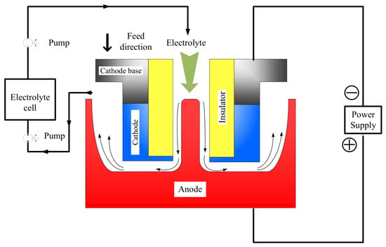
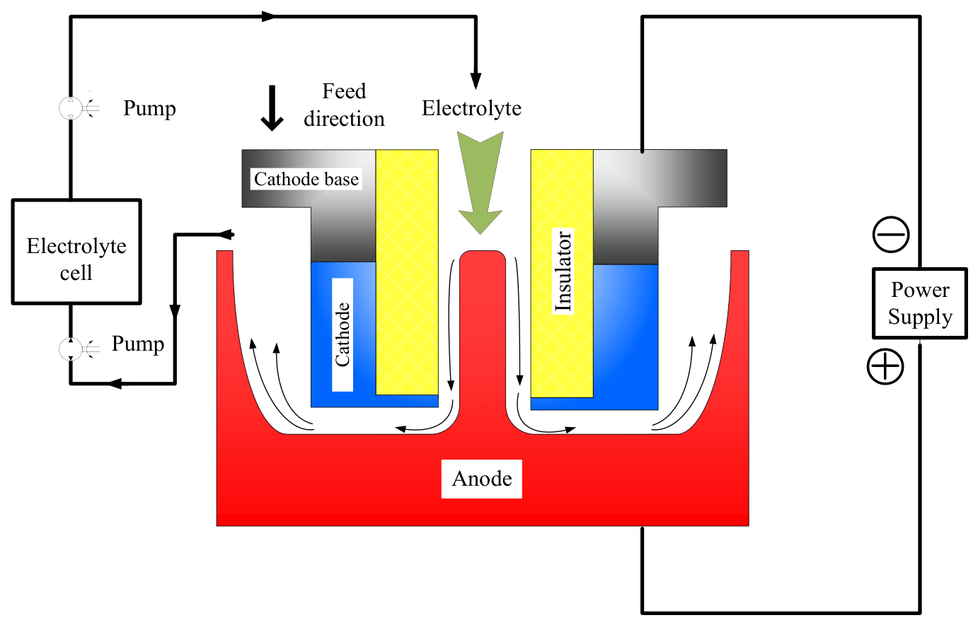
In the electrochemical trepanning (ECT) process, the metallic workpiece is electrically connected to the anode terminal of the power supply system, while the machining tool cathode is firmly connected to the corresponding cathode pole, as shown in Figure 1. This establishes a complete closed electrochemical reaction circuit for material removal. It has been established that the circulating electrolyte flows steadily through the internal flow channel of the tubular cathode electrode. This flowing electrolyte medium fulfils multiple critical functions, which primarily include the timely flushing and removal of various electrochemical reaction by-products generated in the micro-machining gap. Such by-products include insoluble metal oxidation sludge, residual electrolytic sediments and accumulated Joule heat produced by continuous current conduction. The workpiece material undergoes controllable anodic dissolution layer by layer, enabling the workpiece to be accurately shaped into the predefined target profile with the linear feeding motion of the cathode tool. This process is facilitated by the stable electric field distribution and continuous electrolyte renewal in the inter-electrode gap.
Figure 1.
Processing diagram of electrochemical trepanning.
Nevertheless, inevitable stray electric streamlines commonly appear around the machining area on the processed workpiece surface throughout the ECT operation. The presence of disordered and scattered electric field lines has been shown to induce uncontrolled local micro-dissolution behaviour. This has been demonstrated to easily trigger diverse surface defects, which ultimately leads to unsatisfactory surface quality of the final machined workpiece. It is noteworthy that the degree of stray dissolution and the resultant surface machining performance vary significantly under distinct electrical machining modes, especially between conventional direct current power supply and high-frequency pulsed current power supply conditions.
3. Simulation
In order to analyze the forming process, a simulation of the ECT process was conducted under pulsed current or direct current by software COMSOL. The establishment of a material dissolution model for the ECT process was a prerequisite for the subsequent dynamic shaping process. The distribution of the electrical parameters was subsequently subjected to analysis in the context of the machining conditions established by direct current (DC) or pulsed current (PC).
3.1. Physical Model
3.1.1. Geometric Model
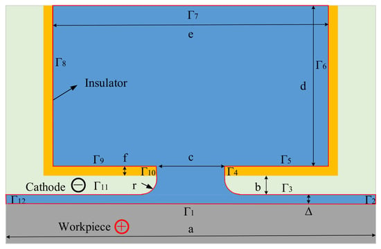
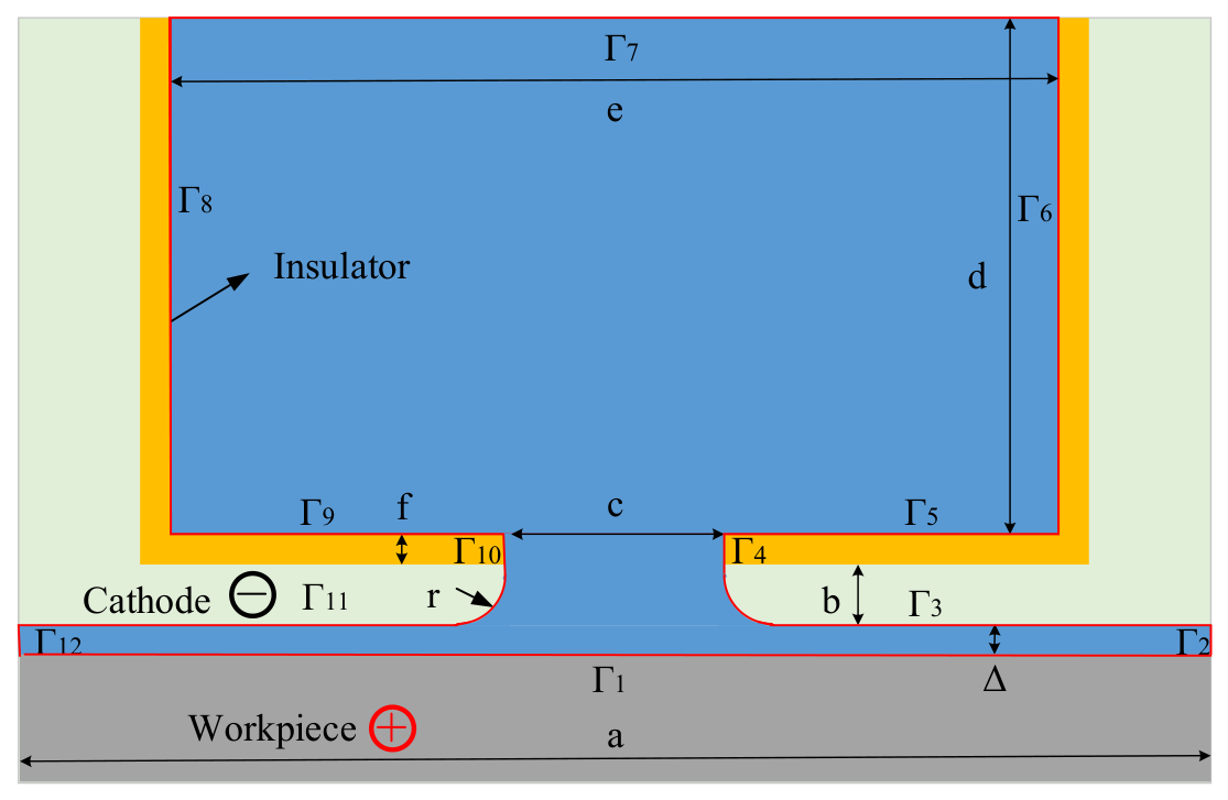
A two-dimensional model of the ECT process using the front flow mode was established (Figure 2). In the geometric model, Δ is the inter-electrode gap between the cathode and the workpiece, r is the radius of the cathode slice, a is the width of the cathode slice, b is the thickness of the cathode slice, c is the width of the cathode inner edge, d is the height of the cathode cavity, e is the width of the cathode cavity, and f is the thickness of the insulator. The geometric parameters in the simulation were as follows: Δ = 0.5 mm, r = 0.8 mm, a = 19.6 mm, b = 1.0 mm, c = 3.6 mm, d = 8.5 mm, e = 14.6 mm, and f = 0.5 mm.
Figure 2.
Geometric model of the initial stage in the ECT process002E.
In electroconvulsive therapy (ECT), it is the action of the electric field that constitutes the driving force of the entire process. The use of a forming simulation enables the prediction of the specimen’s shape following processing. The distribution of the electric field can also be obtained. In order to simplify the problem, it is first necessary to make several assumptions.
- (1)
- The hydrogen and oxygen generated on the tool electrode and anode, respectively, are neglected.
- (2)
- The Joule heat generated between the electrodes is also neglected.
- (3)
- The machining gap is always filled with electrolyte.
- (4)
- The current efficiency curve is constant.
The electrical potential φ in the inter-electrode gap is a critical parameter that influences many other factors, such as current density and the material removal rate. According to ECM theory, φ can be approximately described by Laplace’s equations as follows:
The boundary conditions on the physical model are that
In the simulation, the specific parameters used are given in Table 1. The simulation was performed under direct current and different pulsed currents. The four specific electrical conditions were 20 V; 20 V, 1 kHz, 90%; 20 V, 1 kHz, 86%; and 20 V, 1 kHz, 84%.
Table 1.
Boundary conditions on the simulation model.
3.1.2. Dynamic Mesh
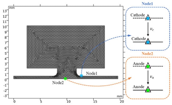
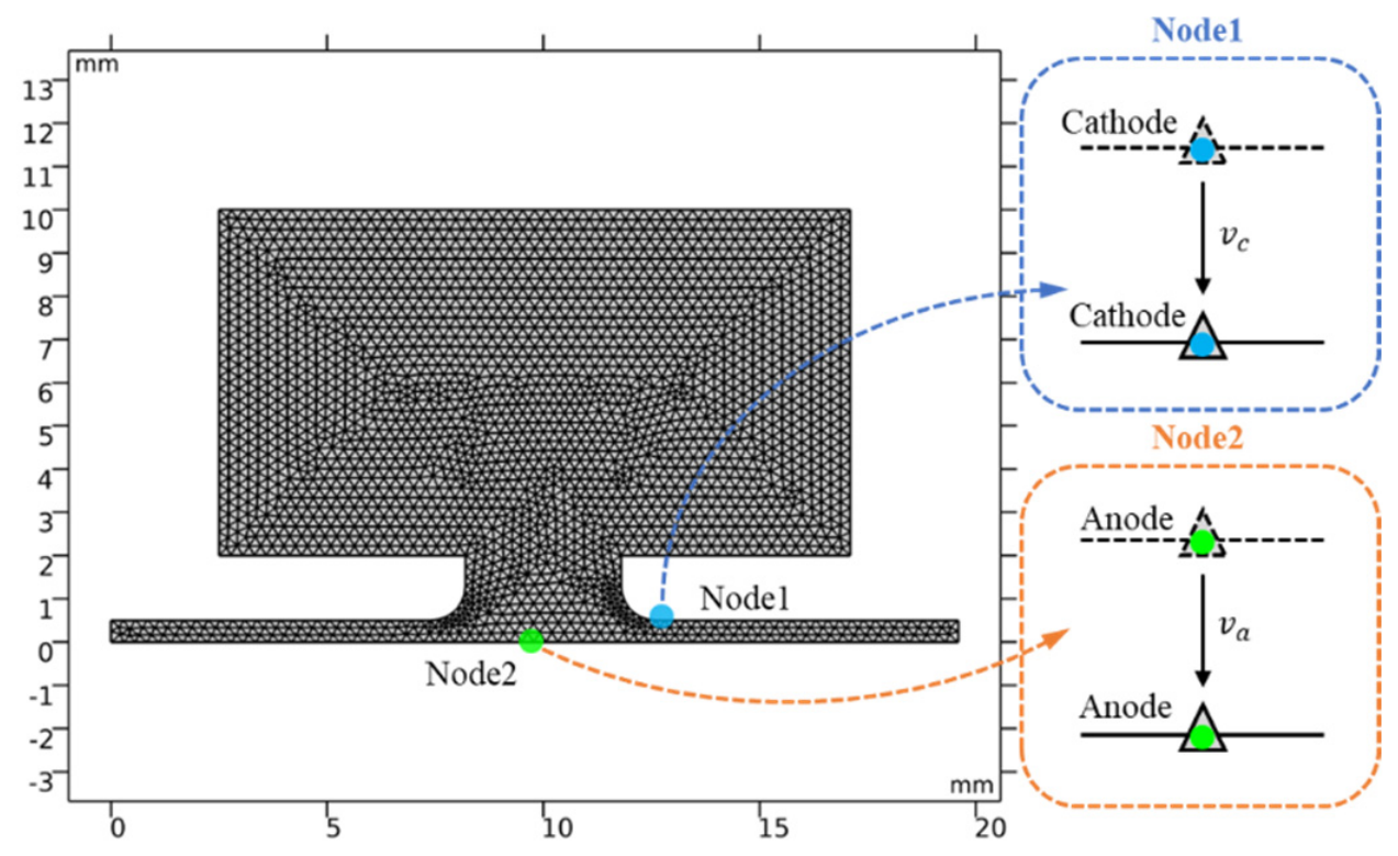
The forming process of ECT was simulated by the dynamic mesh model, as shown in Figure 3. According to Faraday’s laws, the material removal rate va of Node1 on the cathode boundary is proportional to the actual electrochemical equivalent ηω and the current density i.
va = ηωi
Figure 3.
Dynamic mesh model.
With the cathode feed to the workpiece, the workpiece was dissolved according to Equation (6). The simulation was carried out in the dynamic process. The feed rate vc of Node 2 on the cathode was set at 1.6 mm/min, and the voltage of the power supply was set at different values (Table 1).
3.2. Simulation Results
The establishment of the model and the setting of the boundary conditions constituted the initial phase of the study. Subsequently, the execution of the simulation was conducted by employing the software COMSOL.
3.2.1. Current Density Distribution
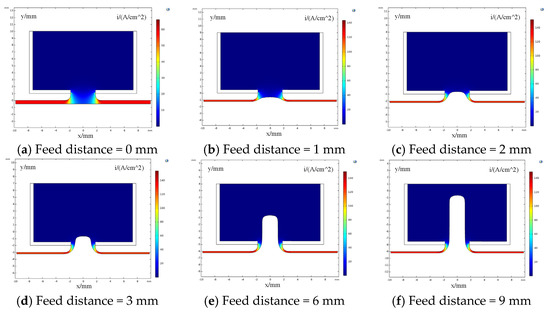
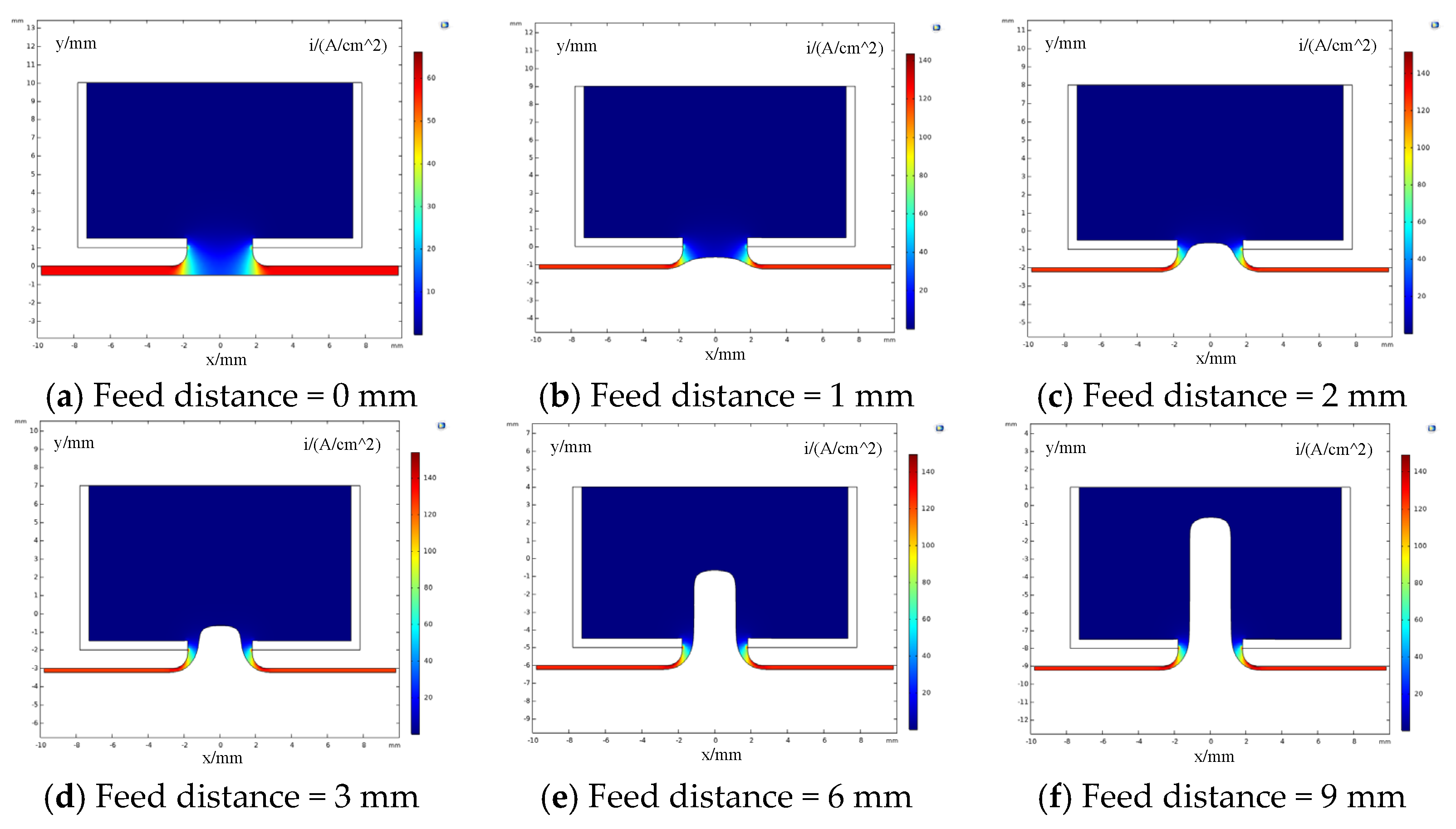
The material removal rate is influenced by the current density, which is a significant factor in this process. The current density distribution in the electrode gap is obtained. The dynamic change in the system under pulsed current (20 kV, 84%, 1 kHz) is demonstrated in Figure 4 for feed distances of 0 mm, 1 mm, 2 mm, 3 mm, 6 mm, and 9 mm. The current density in the front inter-electrode gap is greater than that in the side gap. The values decrease gradually from the bottom to the top of the machined profile. At the uppermost point of the workpiece, the current density is minimal. It is evident that the machined profile exhibits a minor taper, a consequence of the process of scatter dissolution. This trend is consistent across both direct and pulsed current conditions.
Figure 4.
Distribution of the current density under pulsed current conditions (voltage: 20 V, duty ratio: 84%, frequency 1 kHz).
3.2.2. Shaping Process
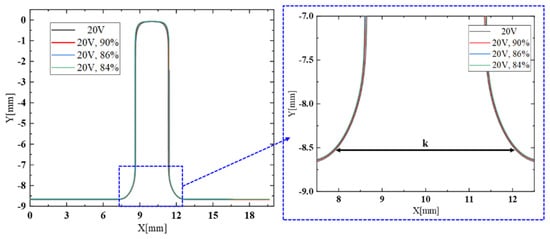
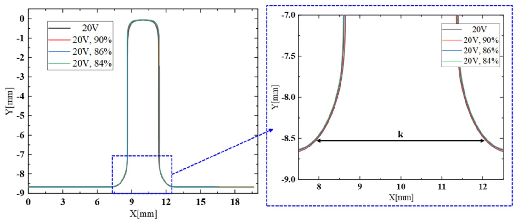
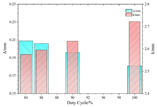
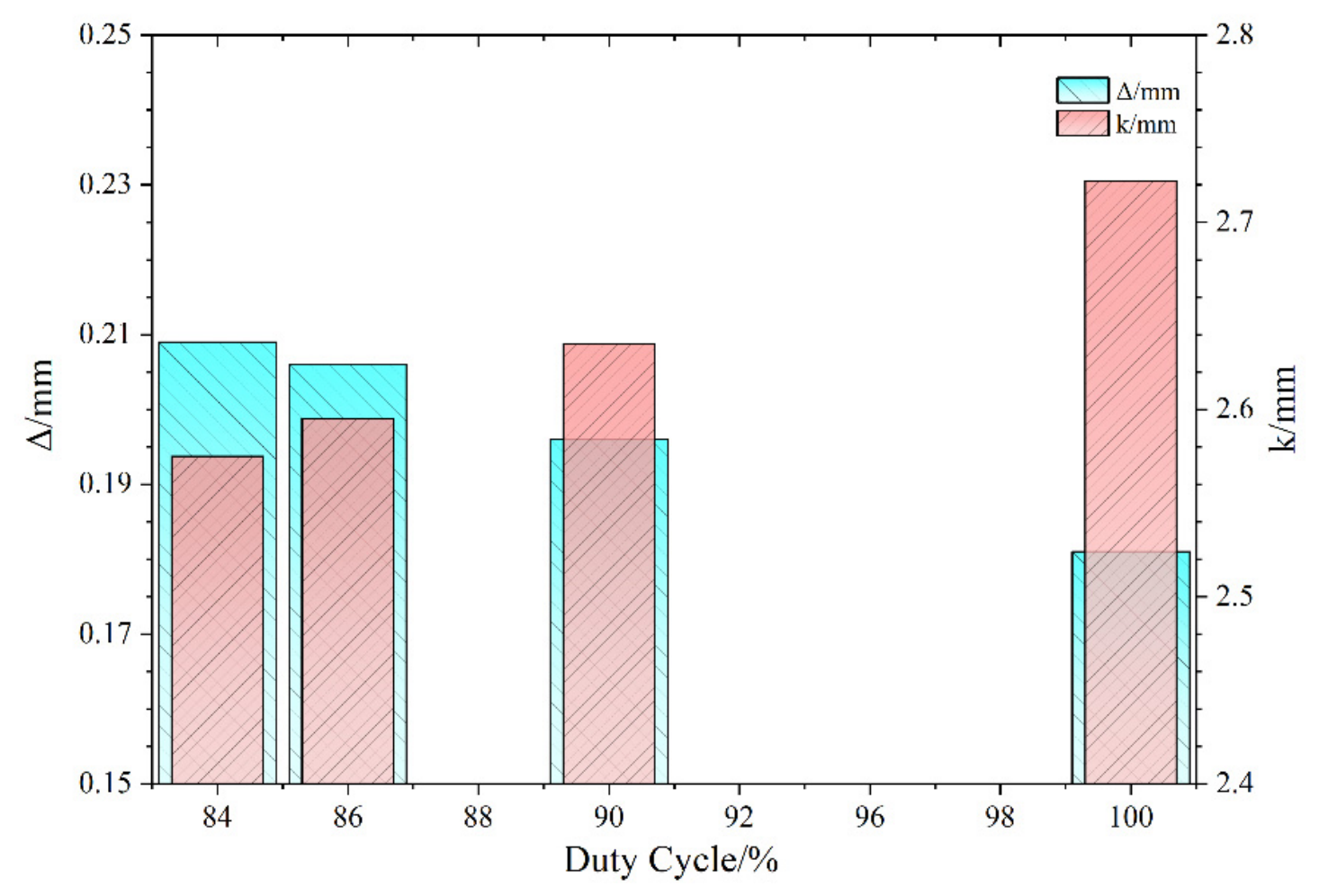
Following the simulation, the machined profile was obtained for both direct current and pulsed current conditions, as illustrated in Figure 5. To analyze the shaping process under direct and pulsed current, the curve for the width of the machined profile at the bottom, defined as k, was calculated in Figure 6. The values obtained were 2.522 mm, 2.586 mm, 2.623 mm, and 2.638 mm under conditions of direct current at 20 V. It is observed that at the base of the workpiece, the side gap is larger under direct current than under pulsed current. The observed change in width is indicative of the diminution of the side gap in the presence of pulsed current. This phenomenon persists in the context of a decreasing duty cycle. Consequently, the machined workpiece may undergo enhanced scatter dissolution under direct current conditions.
Figure 5.
Machined profile under direct current and pulsed current conditions.
Figure 6.
Curves of the width at the bottom of the machined profile and the front inter-electrode gap under direct current and pulsed current conditions.
The front inter-electrode gaps were also measured. The values of 0.232 mm, 0.208 mm, 0.198 mm, and 0.194 mm was obtained under conditions of voltage of direct current 20 V. This finding indicated that the removal of material was more significant under direct current conditions. As the power duty decreased, there was minimal discrepancy between the profile and the current density distribution. Subsequent experiments would be conducted to validate this phenomenon.
4. Experimental Results and Discussion
4.1. Experimental Conditions
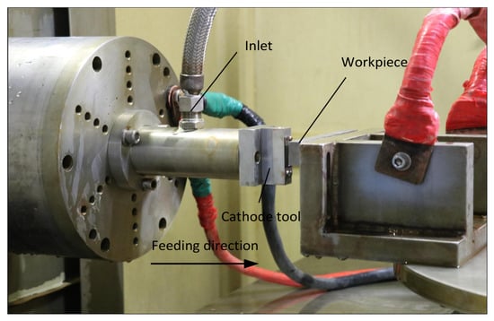
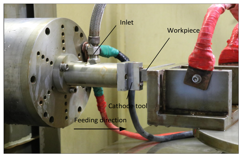
In order to verify the results of the simulation, corresponding experiments were carried out in this study. A front electrolyte flow mode was designed for ECT. And fixtures and a cathode set were manufactured by milling. The experimental setup is illustrated in Figure 7. The machining conditions are detailed in Table 2.
Figure 7.
Picture of experimental setup of ECT.
Table 2.
Experimental conditions for ECT.
The electrolyte used was sodium nitrate at a temperature of 30 °C. The electrolyte pressure was measured at 0.8 MPa at the inlet. The cathode feed rate was 1.6 millimetres per minute, and the feed distance was 9 millimetres. It was established that the electrical parameters were identical to those that had been utilized in the simulation.
4.2. Results and Discussion
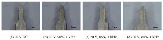
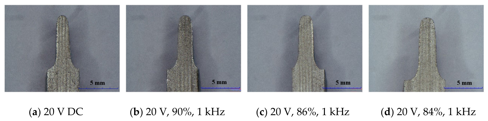
The samples were fabricated under direct current conditions and pulsed current conditions. The experiment was also conducted when the duty ratio was below 84% at a feed rate of 1.6 mm/min. The cross-sections of the samples machined under the four electric parameters were measured by optical microscopy. The machined taper and surface quality were analyzed in the following part of the study.
As demonstrated in Figure 8, the thickness of the samples machined under direct current was found to be less than that obtained under pulsed current. Furthermore, an increase in thickness was observed when the duty cycle decreased. The present phenomenon was in accordance with the simulation results. Furthermore, the taper underwent a reduction in size in conjunction with the decrease in duty cycle, as was shown in Table 3. Specifically, the degree of taper was 3.244° under direct current, whereas it was 2.576° when the pulsed duty cycle was 84%.
Figure 8.
Machined samples under direct and pulsed current conditions.
Table 3.
Taper of the machined profile.
The surface roughness of the machined samples was measured by profile measurement, as was shown in Figure 9. Under the machining condition of DC 20 V, the maximum values obtained for the detect line were Ra 3.33 μm, Ra 2.87 μm, Ra 2.15 μm and Ra 1.88 μm, respectively. The optimum surface roughness was achieved under a duty cycle of 84% at a feed rate of 1.6 mm/min. It had been demonstrated that a decrease in duty cycle, indicative of a strong pulse effect, resulted in the improvement of surface quality and the reduction in scatter dissolution. In conclusion, the optimal electric parameters were as follows: a voltage of 20 V, a duty ratio of 90%, a frequency of 1 kHz, and a feed rate of 1.6 mm/min.
Figure 9.
Surface roughness of the samples under direct current and pulsed current conditions.
5. Conclusions
In the electrochemical machining, the surface morphology and surface quality of machined workpieces were constantly changing because of material removal, which was primarily attributed to the disordered distribution of electric streamlines within the inter-electrode machining gap. To systematically explore the surface quality variation mechanism and clarify the machining performance differences under diverse electrical working conditions, numerical simulation analysis and experimental verification were carried out to compare the machining characteristics under direct current conditions and pulsed current conditions. The core research conclusions summarized from simulations and experiments were presented as follows.
(1) Finite element electric field simulation analyses were implemented via COMSOL Multiphysics software. The current density distribution characteristics within the micro-inter-electrode gap under two typical power supply modes were fully visualized. The results of the simulation study provided a clear and intuitive understanding of the disparities in electric field uniformity, current concentration degree, and streamline diffusion range under varying electrical conditions. This finding offered a substantial theoretical foundation for elucidating the surface quality variations observed in machined components.
(2) Comparative machining experiments were conducted on Inconel 625 superalloy specimens under direct current conditions and pulsed current machining conditions. The experimental results demonstrated that the adoption of a pulsed current could effectively reduce the taper degree of machined workpieces and significantly improve the surface quality. The determination of the optimal electrical matching parameters for ECT machining was achieved through systematic data analysis and performance comparison. The underlying mechanism for the observed enhancement in performance could be attributed to the effective suppression of stray current-induced anodic dissolution on the workpiece surface by the pulsed current. This phenomenon provided a comprehensive explanation for the variation rules of surface quality.
(3) A reduction in the pulse duty cycle would result in a deterioration of machining performance. This negative phenomenon could be attributed primarily to a decrease in effective machining power. When the machining feed rate was set below 1.6 mm/min, the overall machining duration increased accordingly, resulting in excessive anodic dissolution time on the workpiece surface. Following comprehensive parametric optimization and performance evaluation, the optimal machining parameters were confirmed to be a machining voltage of 20 V, a pulse duty cycle of 84% and a pulse frequency of 1 kHz.
Author Contributions
Y.Z.: Writing—original draft, Funding acquisition. Y.L.: Writing—original draft, Writing—review and editing, Funding acquisition. M.R.: Writing—original draft, Writing—review and editing. Z.W.: Writing—original draft, Writing—review and editing, Funding acquisition. All authors have read and agreed to the published version of the manuscript.
Funding
This work was supported by the Funding for school-level research projects of Yancheng Institute of Technology (No. xjr2022008), Science and Technology Program of Zhenjiang (No. JC2025002), China Postdoctoral Science Foundation (No. 2025M771349), Youth Scientific and Technological Talents Encouragement Project of Jiangsu Province (No. JSTJ-2024-171), Open Research Subject of Key Laboratory of Metallurgical Industry Equipment and Control Technology, Ministry of Education (No. MECOF202507), Open Fund of the State Key Laboratory of Material Processing and Die & Mould Technology (No. P2026-55).
Data Availability Statement
The original contributions presented in this study are included in the article. Further inquiries can be directed to the corresponding author.
Conflicts of Interest
The authors declare no conflicts of interest.
References
- Kong, H.; Qu, N.; Chen, J. Machining behaviour modulation of electrochemical milling via manipulation of inter-electrode gap: From electrochemical machining to electrochemical discharge machining. J. Mater. Process. Technol. 2024, 333, 118584. [Google Scholar] [CrossRef] [Scilit]
- Zhang, H.; Qu, N. Phenomena and mechanisms in plasma-enhanced jet electrochemical machining. CIRP J. Manuf. Sci. Technol. 2025, 63, 265–280. [Google Scholar] [CrossRef] [Scilit]
- Yang, C.; Wang, C.; Li, Z.; Chen, X.; Yang, X.; Yin, M.; Wang, W.; Yang, Z. Experimental and simulation study on maximum machining rate of micro holes in laser electrochemical machining of TC4. Int. J. Adv. Manuf. Technol. 2026, 142, 5375–5393. [Google Scholar] [CrossRef] [Scilit]
- Dong, Q.; Jiang, W.; Wang, Y.; Zhang, L.; Tan, J.; Xiong, X.; Liu, B.; Yang, Y.; Zhang, W. Ultra-high aspect ratio micro holes drilling by laser and electrochemical machining via enhanced mass transport in the machining gap. Int. J. Adv. Manuf. Technol. 2026, 143, 1657–1677. [Google Scholar] [CrossRef] [Scilit]
- Shen, M.; Duan, S.; Zhou, Z.; Zhang, Z.; Liu, J.; Zhu, D. Dependency of the pulse dynamic electrochemical machining characteristics of Allvac 718 plus in NaNO3 solution on the machining paraments. J. Mater. Res. Technol. 2025, 35, 892–910. [Google Scholar] [CrossRef] [Scilit]
- Bergs, T.; Harst, S. Development of a process signature for electrochemical machining. CIRP Ann. 2020, 69, 153–156. [Google Scholar] [CrossRef] [Scilit]
- Yang, Y.; Wang, Y.; Yang, J.; Liu, Y.; Zhang, W. High-efficiency and stable laser transmission for laser and electrochemical machining. Opt. Laser Technol. 2024, 179, 14. [Google Scholar] [CrossRef] [Scilit]
- Yang, P.-J.; Hung, J.-C. On high resolution bubbly flow generator for gas-mixed micro electrochemical machining. J. Manuf. Process. 2024, 121, 269–288. [Google Scholar] [CrossRef] [Scilit]
- Liu, Y.; Qu, N.; Li, H.; Zhang, Z. Boundary fluid constraints during electrochemical jet machining of large size emerging titanium alloy aerospace parts in gas–liquid flows: Experimental and numerical simulation. Chin. J. Aeronaut. 2025, 38, 103024. [Google Scholar] [CrossRef] [Scilit]
- Li, T.; Wang, Y.; Jiang, W.; Yang, Y.; Zhang, W. Study of laser-electrochemical machining of deep small holes based on lensed fiber coupling. J. Mater. Res. Technol. 2026, 42, 5296–5307. [Google Scholar] [CrossRef] [Scilit]
- Ren, M.; Zhu, D.; Zhou, X.; Wang, Y.; Li, S. Surface quality enhancement in ultrasonic vibration-assisted electrochemical machining. Colloids Surf. A Physicochem. Eng. Asp. 2024, 703, 16. [Google Scholar] [CrossRef] [Scilit]
- Wang, Y.; Xu, Z.; Liu, J.; Zhang, A.; Xu, Z.; Meng, D.; Zhao, J. Study on flow field of electrochemical machining for large size blade. Int. J. Mech. Sci. 2021, 190, 106018. [Google Scholar] [CrossRef] [Scilit]
- Cao, S.; Wang, D.; Ren, J.; Zhang, J. Improvement on the machining accuracy of electrochemical machining by using an insoluble auxiliary anode. Int. J. Adv. Manuf. Technol. 2026, 143, 361–374. [Google Scholar] [CrossRef] [Scilit]
- Xiulei, Y.; Zhidong, L.; Ying, S.C. Effect of atomization amounts on electrical discharge ablation machining and electrochemical machining. Mater. Manuf. Processes 2024, 39, 1537–1550. [Google Scholar] [CrossRef] [Scilit]
- Zhang, Q.; Natsu, W.; Luo, H. Realization of high-precision electrochemical machining by active use of hydrogen bubbles generated in non-machining area. Precis. Eng. 2024, 91, 59–76. [Google Scholar] [CrossRef] [Scilit]
- Xue, L.; Qu, N.; Ding, W. Impact of electrochemical machining parameters on the electrochemical grinding process. Mater. Manuf. Process. 2025, 40, 594–602. [Google Scholar] [CrossRef] [Scilit]
- Qin, G.; Peng, H.; Zhang, Y.; Ming, P.; Liu, H.; Wu, X.; Zhang, W.; Zheng, X.; Niu, S. Hard Particle Mask Electrochemical Machining of Micro-Textures. Materials 2024, 17, 4986. [Google Scholar] [CrossRef] [Scilit] [PubMed]
- Wang, Y.; Zhang, X.; Xu, Z. Passive behavior of TNB intermetallic and Inconel 625 in electrochemical machining. Appl. Surf. Sci. 2025, 681, 161433. [Google Scholar] [CrossRef] [Scilit]
- Fan, S.; Wang, Y.; Fang, J.; Yang, Y.; Xu, Y.; Pang, G.; Han, C.; He, Z. Research Progress of Electrochemical Machining Technology in Surface Processing: A Review. Micromachines 2025, 16, 1174. [Google Scholar] [CrossRef] [Scilit] [PubMed]
- Huang, Y.; Xu, Y.; Fang, C.; Gong, S.; Wang, X.; Speidel, A.; Chen, X.; Liu, F. Flow field design and process parameter experiments in electrochemical machining of involute internal spline. Int. J. Adv. Manuf. Technol. 2026, 143, 2451–2471. [Google Scholar] [CrossRef] [Scilit]
- Liu, Y.; Fang, X.; Qu, N.; Zhang, Z.; Lu, J. Simultaneous gas electrical discharge and electrochemical jet micromachining of titanium alloy in high-conductivity salt solution. J. Mech. Work. Technol. 2023, 317, 118340. [Google Scholar] [CrossRef] [Scilit]
- Tong, F.; Ren, W.; Xu, J.; Deng, H.; Sun, H.; Zhao, J. Research on improving profile accuracy of electrochemical machining of twisted blades based on flow field uniformity. Mater. Today Commun. 2025, 42, 111561. [Google Scholar] [CrossRef] [Scilit]
- Qin, G.; Li, M.; Han, L.; Ming, P.; Niu, S.; Yan, L.; Zheng, X.; Zhang, X.; Li, S. Electrochemical machining process for micropit arrays using a rolling device with a linear cathode and a soft mask. Int. J. Adv. Manuf. Technol. 2024, 131, 2653–2665. [Google Scholar] [CrossRef] [Scilit]
- Jiao, E.; Zhu, D.; Wang, P.; Zuo, H.; Chen, L. Predicting the evolution of electrochemical trepanning for inner blisks with a chamfer structure at blade tip. Chin. J. Aeronaut. 2024, 37, 560–576. [Google Scholar] [CrossRef] [Scilit]
- Jiao, E.; Zhu, D.; Wang, Y.; Wang, R. Design of multi-electrode synchronized electrochemical trepanning with rotational feeding system for inner twisted blisk. Precis. Eng. 2026, 98, 206–223. [Google Scholar] [CrossRef] [Scilit]
- Lei, G.; Zhu, D.; Ren, M.; Jiao, E.; Xie, Y.; Li, M. Multi-Channel Electrolyte Supply for Electrochemical Trepanning of Blisks Using Rotational Feeding Combined with Shift Feeding. Chin. J. Mech. Eng. 2025, 38, 33. [Google Scholar] [CrossRef] [Scilit]
- Lei, G.; Zhu, D.; Li, J. Optimization of flow field in electrochemical trepanning of integral cascades (Ti6Al4V). Chin. J. Aeronaut. 2021, 35, 354–364. [Google Scholar] [CrossRef] [Scilit]
- Jiang, T.; Zhu, D.; Lei, G. Electrochemical trepanning with an auxiliary electrode. Chin. J. Aeronaut. 2020, 34, 183–194. [Google Scholar] [CrossRef] [Scilit]
- Lei, G.; Zhu, D.; Zhu, D. Research on multiphysics coupling fields in electrochemical trepanning of lateral flow. Int. J. Adv. Manuf. Technol. 2022, 119, 5131–5141. [Google Scholar] [CrossRef] [Scilit]
- Lei, G.; Zhu, D.; Zhu, D. Feeding strategy optimization for a blisk with twisted blades in electrochemical trepanning. J. Manuf. Processes 2021, 62, 591–599. [Google Scholar] [CrossRef] [Scilit]
- Xu, J.; Zhu, D.; Lin, J.; Hu, X. Flow field design and experimental investigation of electrochemical trepanning of diffuser with a special structure. Int. J. Adv. Manuf. Technol. 2020, 107, 1551–1558. [Google Scholar] [CrossRef] [Scilit]
- Jiao, E.; Zhu, D.; Zhang, C.; Wang, P.; Zuo, H. Research on the characteristics of multiphysics coupling fields in the electrochemical trepanning of an inward facing blisk. J. Manuf. Process. 2023, 93, 60–74. [Google Scholar] [CrossRef] [Scilit]
- Gu, Z. Simulation and Experimental Investigation of Electrochemical Trepanning of an Aero-Engine Diffuser with Different Flow Fields. Int. J. Electrochem. Sci. 2021, 16, 211144. [Google Scholar] [CrossRef] [Scilit]





Disclaimer/Publisher’s Note: The statements, opinions and data contained in all publications are solely those of the individual author(s) and contributor(s) and not of MDPI and/or the editor(s). MDPI and/or the editor(s) disclaim responsibility for any injury to people or property resulting from any ideas, methods, instructions or products referred to in the content. |
© 2026 by the authors. Licensee MDPI, Basel, Switzerland. This article is an open access article distributed under the terms and conditions of the Creative Commons Attribution (CC BY) license.