


Abstract
In ultra-supercritical (USC) power plants, P92 steel welded joints are continuously subjected to creep-fatigue (CF) loading, rendering them susceptible to premature cracking during service. To investigate the CF interaction behavior, CF tests were performed on P92 steel welded joints at 650 °C under various dwell times. The results indicate that prolonged dwell periods progressively shorten the cycle life. Scanning electron microscopy (SEM) observations reveal that with increasing dwell time, the fracture mechanism of the P92 steel gradually transitions from a fatigue-dominated failure mode to one governed by creep-fatigue interaction damage. Subsequently, nanoindentation was employed to evaluate the hardness (H), elastic modulus (E), and creep deformation, based on which the strain rate sensitivity (m) was estimated and the underlying damage mechanisms were thoroughly discussed.
1. Introduction
Benefiting from the addition of tungsten and boron, P92 martensitic steel demonstrates exceptional high-temperature creep strength alongside outstanding oxidation and corrosion resistance. Consequently, it is extensively utilized in the critical components of USC power plants, such as superheaters, main steam pipes, and reheaters [1]. In the fabrication and installation of large-scale pressure piping networks, welding serves as an indispensable joining technology. Nevertheless, welded joints inherently possess significant heterogeneity in both metallurgical structure and mechanical properties—typically consisting of the base metal, weld metal, and a microstructurally complex HAZ—and are historically recognized as the weakest links within the system [2,3]. Over long-term service involving continuous peak-shaving and frequent start-up/shut-down cycles, high-temperature components like USC main steam pipes suffer from complex damage driven by high-temperature fatigue, creep, and their interactions. These interactions severely accelerate microstructural degradation and crack initiation, potentially culminating in the premature failure of welded joints, particularly at operating temperatures exceeding 600 °C [4,5,6]. Therefore, an in-depth investigation into the high-temperature CF behavior and the underlying failure mechanisms of P92 steel welded joints is of paramount importance.
For components subjected to creep-fatigue loading, it is imperative to consider the impact of creep-fatigue interaction on the mechanical properties of the material, in addition to the independent damage induced by pure creep and fatigue. Previous studies have demonstrated that under high-temperature environments, M23C6 carbides within the lath martensitic structure of P92 steel undergo coarsening, accompanied by the gradual precipitation of coarse Laves and MX phases. This microstructural evolution degrades the creep resistance of the material, ultimately culminating in failure [7,8]. Furthermore, during service, creep cavities nucleate and grow at the grain boundaries of martensitic heat-resistant steels. As service time is prolonged, these cavities coalesce to form microcracks along the grain boundaries, eventually leading to failure [9,10,11]. This weakening of creep resistance has a very significant impact on the FGHAZ of P92 steel welded joints, often leading to cracking in the FGHAZ of the welded joints under low stress [12]. This failure mode is not only related to the coarsening of carbides at the grain boundaries in the FGHAZ and the precipitation of carbides detrimental to creep properties [13,14], but is also closely related to the creep cavities caused by grain boundary sliding around the fine grains [15]. In addition, loading factors also significantly affect the creep-fatigue life of the material, including hold time, strain amplitude, hold mode, and loading rate.
Creep-fatigue interaction tests with hold times closely match the actual service conditions of most high-temperature structural components, and therefore, they are widely applied in the research of CF interaction. Researchers have demonstrated that under constant temperature and maximum load conditions, the cyclic life is inversely proportional to both the stress ratio and the dwell time [16,17]. Nevertheless, once the dwell time exceeds a certain threshold, the dependence of the fatigue life on the stress ratio diminishes. Furthermore, creep-fatigue experiments conducted on materials such as P91/P92 steels and austenitic stainless steels reveal that prolonged dwell periods exacerbate the accumulated creep damage during the hold phase (manifested by an increase in the density and size of creep microcavities), particularly in the vicinity of the crack tip, which results in a shorter cycle life [18,19,20]. Other studies have shown that an increase in strain rate will cause the fracture location of creep-fatigue tests to shift from the FGHAZ region to the BM region [21]. Due to the susceptibility of the oxide layer to cracking, creep-fatigue specimens with compressive holds also have a shorter cycle life than those with tensile holds, and this phenomenon is more obvious at low strain amplitudes [22,23]. Although considerable attention has been paid to the effects of dwell time, strain amplitude, strain rate, and hold mode on the CF life of heat-resistant steels, the CF fracture mechanisms of welded joints have not been extensively studied because the creep resistance near the crack is difficult to measure. The nanoindentation technique now provides an opportunity to measure the local creep resistance and other mechanical properties near the fracture edge of specimens that have undergone CF fracture. Investigating the mechanical properties and microstructural evolution near the fracture surface can elucidate the fracture mechanisms of welded joints under CF loading. Our previous studies on P92 steel [3,24,25] investigated the local creep behavior of welded joints under CF loading and discussed the effect of hold type (i.e., tensile or compressive) on the creep behavior of welded joints. However, the effect of specific dwell times on the creep behavior and its fracture mechanism remains unclear.
The work reported in this paper focuses on the local creep behavior and fracture mechanisms of P92 steel welds after pre-loading with different tensile dwell times. Strain-controlled creep-fatigue tests incorporating various dwell times were performed on the welded joint specimens at 650 °C. Subsequently, nanoindentation was employed to determine the hardness and elastic modulus of the fractured regions. Ultimately, the correlation between the degraded mechanical properties and microstructural characterization was established, and the underlying damage mechanisms were comprehensively discussed.
2. Materials and Experimental Procedures
2.1. Materials
The experimental material used in this study was a thick-walled A335 P92 steel pipe manufactured by Zhejiang Jindun Pressure Vessel Co., Ltd. (Shaoxing, China) with an outer diameter of 840 mm, a wall thickness of 80 mm, and a length of 600 mm. Two pipe sections were welded together using either GTAW or SAW. To relieve residual stresses, the pipe was heat-treated at 760 °C for 2 h, followed by natural cooling in air. The chemical compositions of P92 steel are listed in Table 1, which meets the requirements of ASME SA-335 standard [26].
Table 1.
Chemical compositions of P92 steel (wt.%).
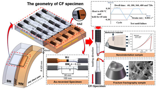
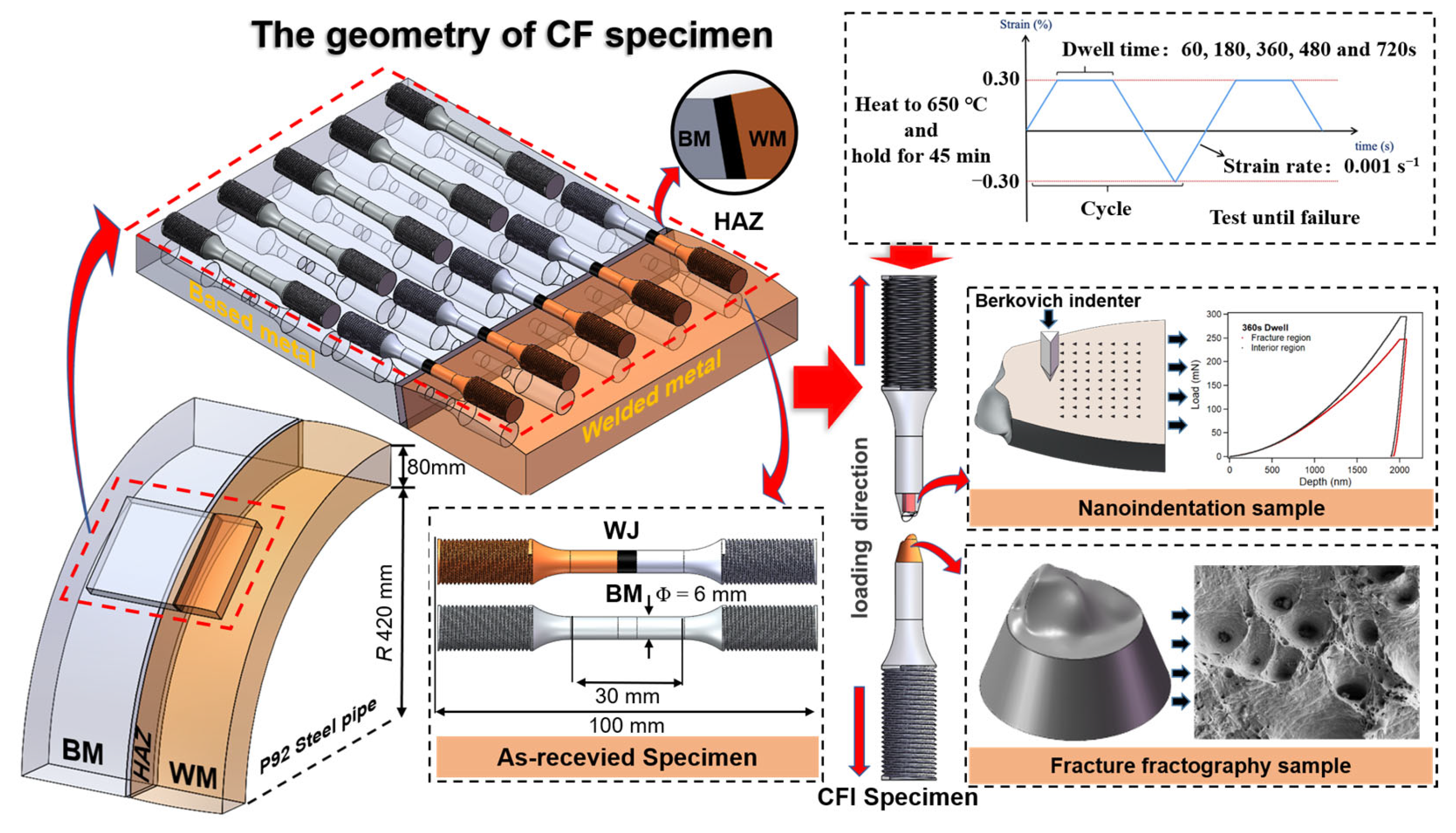
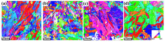
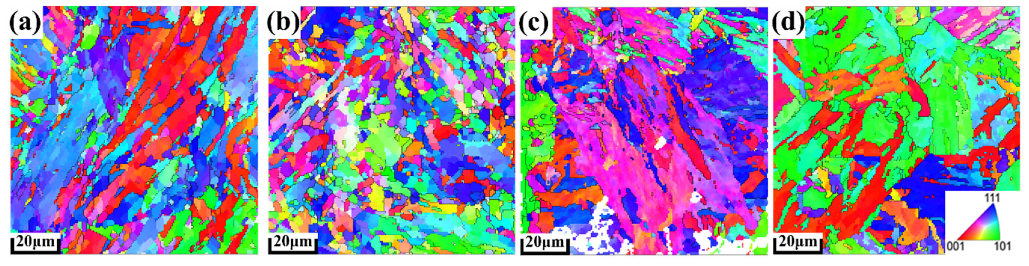
As shown in Figure 1, all specimens were extracted along the through-thickness direction of the pipe using EDM, with their loading axis aligned parallel to the axial direction of the pipe. To ensure uniform initial mechanical properties across all samples, the specimens were consistently machined from identical locations within the welded joint. The specimen has a diameter of 6.0 mm and a gauge length of 30 mm. The microstructures of the BM, FGHAZ, CGHAZ, and WM were examined using EBSD, and IPF images of typical regions are shown in Figure 2a–d. The BM region exhibits a typical tempered martensite lath structure with a random orientation distribution. Under the effect of welding thermal cycles, the microstructure of the heat-affected zone underwent significant changes. In the FGHAZ region, the prior austenite grains and martensite blocks are significantly refined due to the recrystallization process. Conversely, in the CGHAZ region adjacent to the fusion line, the prior austenite grains experienced severe coarsening due to the extremely high peak temperatures, resulting in exceptionally large martensite blocks formed within them. The WM region displays a typical as-cast or post-weld heat-treated martensitic microstructure. Such microstructural heterogeneity will directly affect the mechanical properties of the different regions within the welded joint.
Figure 1.
P92 specimens (mm) and experimental procedures.
Figure 2.
IPF images of the BM (a), FGHAZ (b), CGHAZ (c), and WM (d) regions in the as-welded P92 welded joint.
2.2. Creep-Fatigue Experiment
CF experiments were performed in a high-temperature electronic creep-fatigue testing machine (RPL 300, Sinotest Equipment Co., Ltd., Shanghai, China) and the maximum loading capacity is 100 KN). The typical operating and design temperature range for structural components in advanced USC power plants is 550 °C to 650 °C. To fully consider the creep-fatigue interaction, 650 °C was selected as a highly representative service temperature to conduct the tests. Symmetric trapezoidal waveforms were used in the CF tests, and a matrix of test parameters used in the CF experiments is given in Figure 1. The strain rate was kept constant at 0.001 s−1, while the dwell time and strain amplitudes were different for each specimen (Table 2). One specimen was tested under each of the five loading conditions (dwell times of 60, 180, 360, 480, and 720 s). The dwell times were selected primarily to facilitate comparison with previous findings on P92 steel base metal and 316H stainless steel. The gauge length change in the specimen was measured using an extensometer (Epsilon Technology corp, Wyoming, WY, USA), the gauge length is 25 mm and the resolution is 0.001 mm) during the CF tests, with a data acquisition frequency of 10 Hz. All specimens were held for at least 45 min at 650 °C before the CF experiments started to ensure a uniform temperature in them. Temperature variation during testing was maintained at <±1 °C using three S-type thermocouples, which were fixed to the top, middle, and bottom of the specimen.
Table 2.
Experimental creep-fatigue test parameters and test results at 650 °C.
EBSD were employed to characterize the microstructures of the material after the creep-fatigue tests. For the failed specimens, EBSD samples were sectioned from the gauge section, away from the macroscopic fatigue crack and mechanically polished to a mirror finish. Furthermore, the fracture morphologies of the tested specimens were examined using SEM to identify the sites of crack initiation and early crack propagation.
2.3. Nanoindentation Testing
Nanoindentation experiments were conducted on an Agilent Nano Indenter G200 system (KLA Instruments, San Mateo, CA, USA) at room temperature. Samples were extracted from the as-received and creep-fatigue specimens using EDM. Prior to nanoindentation, all specimens were sequentially ground using 400-, 800-, 1500-, 2000-, and 3000-grit metallographic abrasive papers, and then polished with a silk velvet cloth (W 0.5–1.5 μm) on an ultra-precision polishing machine (MP-1A). Subsequently, fine polishing was conducted for 10 h on a vibratory polisher (UniPOL V1200, MEGA INSTRUMENTS, Suzhou, China) using a polyurethane pad and a 2 μm diamond suspension, until a mirror-like surface finish was achieved. All specimens tested included microstructures from the fracture regions. Using a standard Berkovich indenter (KLA Instruments, San Mateo, CA, USA), the nanohardness and elastic modulus of each region were first measured using the CSM technique [27] at a strain rate of 0.05 s−1, and the maximum depth of indentation was 2000 nm. The CSM technique allows measurement of depth-dependent properties of materials in a single step process. The method involves applying a dynamic load superimposed on the static load during loading. The dynamic part of the load is then used to measure the stiffness, which can be further processed to calculate the modulus and hardness of the material. To ensure reliability, we conducted 6 indentation tests at each location and used the average values.
3. Results and Discussion
3.1. Creep-Fatigue Behavior
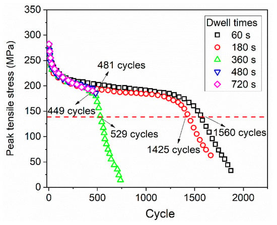
Creep-fatigue results are summarized in Table 2 for P92 welded joint specimens. As expected, the cyclic lives are inversely proportional to the dwell times at tension. As the dwell time increases from 60 s to 720 s, the creep-fatigue life decreases from 1560 to 449 cycles. Furthermore, as the dwell period is extended from 180 s to 360 s, the creep-fatigue life experiences a substantial decline. This phenomenon is not exclusive to P92 welded joints; analogous behaviors have also been well-documented in investigations concerning 316H stainless steel [28] and welding 7050-T7451 aluminum alloys [29].
Figure 3 further illustrates the evolution of peak tensile stress with the number of cycles during the creep-fatigue tests. As illustrated in the Figure 3, P92 steel welded joints exhibit two distinct cyclic softening behaviors when subjected to long (480 and 720 s) and short (60, 180, and 360 s) dwell periods. For specimens with a dwell time of less than 360 s, three typical stages of cyclic softening can be observed. The first stage is characterized by a rapid decay in peak tensile stress, which decreases sharply from 280 MPa to 180 MPa within the initial few hundred cycles. In the second stage, the reduction rate of the peak tensile stress slows down significantly, remaining relatively stable in the range of 170 to 190 MPa. The third stage exhibits a secondary drastic drop in peak tensile stress, ultimately leading to specimen fracture. In contrast, specimens with longer dwell times (480 s and 720 s) also display obvious first and second stages of cyclic softening, but do not exhibit the third-stage softening characteristic seen in the short-dwell-time specimens. Similar phenomena have also been observed in creep-fatigue investigations of the P92 base metal: with prolonged dwell periods exceeding 300 s, the tertiary stage of the base metal specimens disappears completely. Cyclic softening is a typical characteristic of 9Cr ferritic-martensitic steels [30,31], which is usually attributed to a combination of multiple factors: the breakdown of martensitic lath boundaries [32], the development of cellular or sub-grain structures [33], the reduction in dislocation density through annihilation [34], and the growth of surface oxide layers [35,36]. This ultimately leads to a rapid decrease in the peak stress during the initial stage. Previous studies have indicated that the significant decrease in peak tensile stress during the third stage in the P92 steel base metal is primarily associated with the initiation and propagation of macroscopic cracks, which leads to a continuous reduction in the applied tensile load until specimen failure [24]. Nevertheless, prolonged dwell times induce a transition in the failure mode from pure fatigue to creep-fatigue, ultimately resulting in the elimination of the tertiary stage. Since the specimens were heat-treated prior to the experiments and the surface residual stress measured by XRD did not exceed 50 MPa, the effect of residual stress on the creep-fatigue test results is not discussed here.
Figure 3.
Evolution of peak tensile stress as a function of cycle number during creep-fatigue tests with different dwell times.
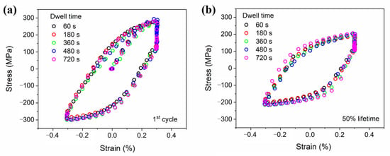
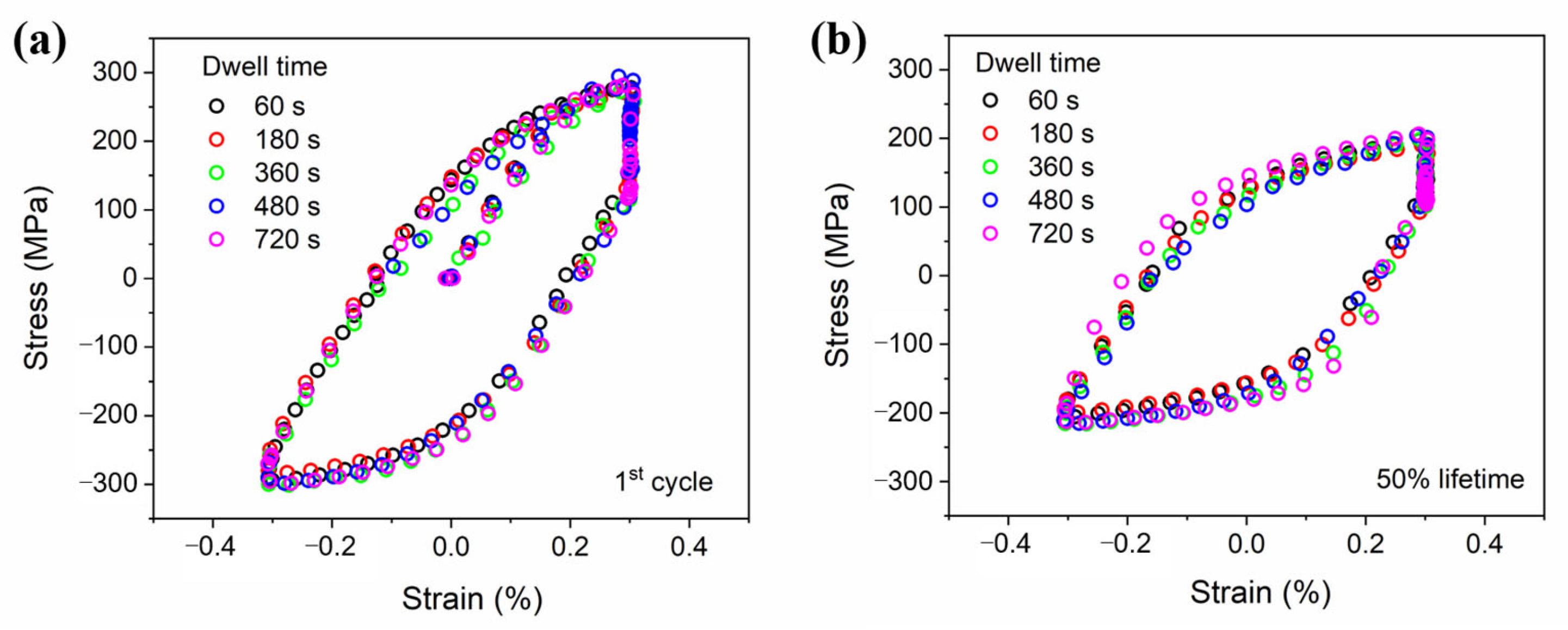
Under strain-controlled creep-fatigue loading waveforms, the cyclic stress−strain hysteresis loop is another important macroscopic mechanical feature for describing creep-fatigue damage, especially at the half-life cycle. Figure 4a,b present the stress−strain hysteresis loops recorded at the initial cycle and the half-life cycle under different dwell times, respectively. Stress relaxation behavior is evident during the tensile dwell period across all hysteresis loops, regardless of the applied dwell time. The hysteresis loops of specimens with different dwell times nearly coincide in the first cycle. However, at the half-life cycle, the hysteresis loop area of the specimen with a 720 s dwell time is significantly larger than those of the other samples. This reflects the influence of dwell time on the stress relaxation behavior. Veerababu et al. [36] reported that DSA occurs in Grade 92 steel welded joints at 550 °C, but the experimental results in this study provide no obvious evidence for the existence of the DSA phenomenon.
Figure 4.
The stress−strain hysteresis loops measured at the first cycle (a) and the half-life cycle (b) under different dwell times.
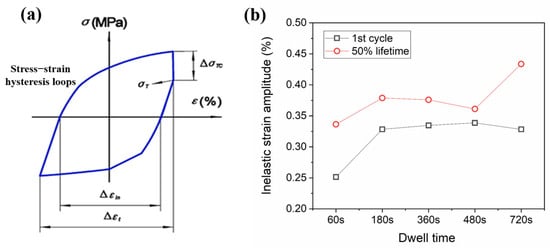
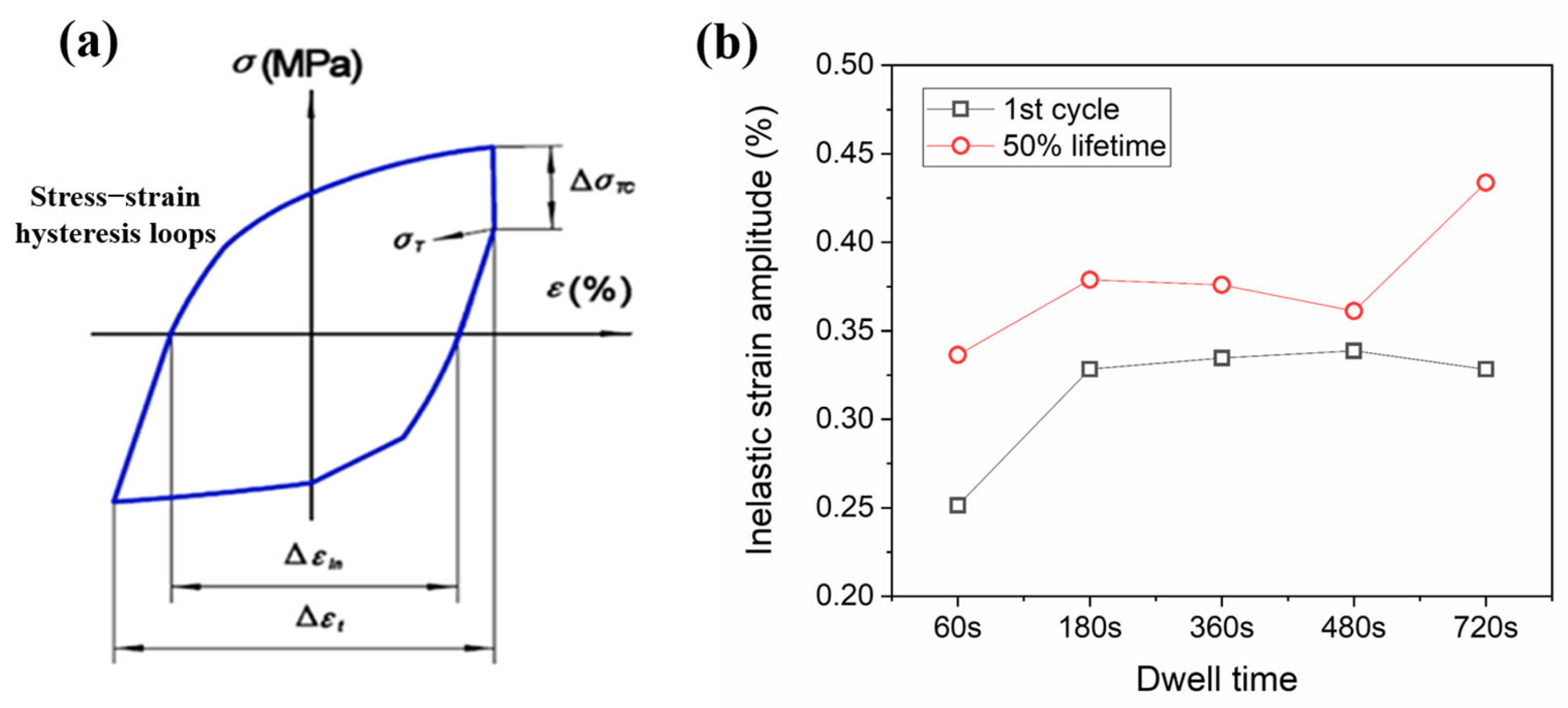
The accumulation of inelastic strain under creep-fatigue loading serves as another crucial metric for characterizing creep-fatigue behavior. The inelastic strain, denoted as εin, can be directly extracted from the stress−strain hysteresis loops [24], as depicted in Figure 5a. Figure 5b presents the corresponding inelastic strains acquired at the initial cycle and the half-life cycle. Notably, with the exception of the specimen subjected to a 60 s dwell time, the inelastic strain during the first cycle consistently remains at approximately 0.33%. This can presumably be attributed to the relatively short dwell time, under which fatigue damage remains the dominant mechanism within the specimen. Creep-fatigue interactions significantly accelerate inelastic strain accumulation; as the dwell time increases, the inelastic strain at the half-life cycle can reach up to 0.45%. Previous research [33] has demonstrated that a higher inelastic deformation corresponds to a significant increase in the GND density within the fracture region of P92 steel. It was also reported that during higher inelastic deformation, extensive dislocation network structures form within the block grains. The storage and rearrangement of these dislocation networks refine the original grains, leading to an increased local frequency density of HAGBs at the fracture edge of creep-fatigue specimens under a 900 s tensile hold. Therefore, based on the increased inelastic strain observed in our present study, it is reasonable to deduce that grain boundaries rearrange at high temperatures to accommodate more dislocations. Once dislocations are accommodated at the grain boundaries, the boundaries undergo structural rearrangement and tend toward a new equilibrium state, indicating that a certain degree of recovery occurs.
Figure 5.
(a) Schematic diagram of stress−strain hysteresis loop during the CF test [24]; (b) the inelastic strains εin obtained in the first cycle and the half-life cycle with different dwell times.
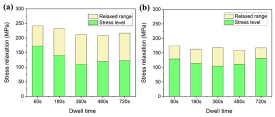
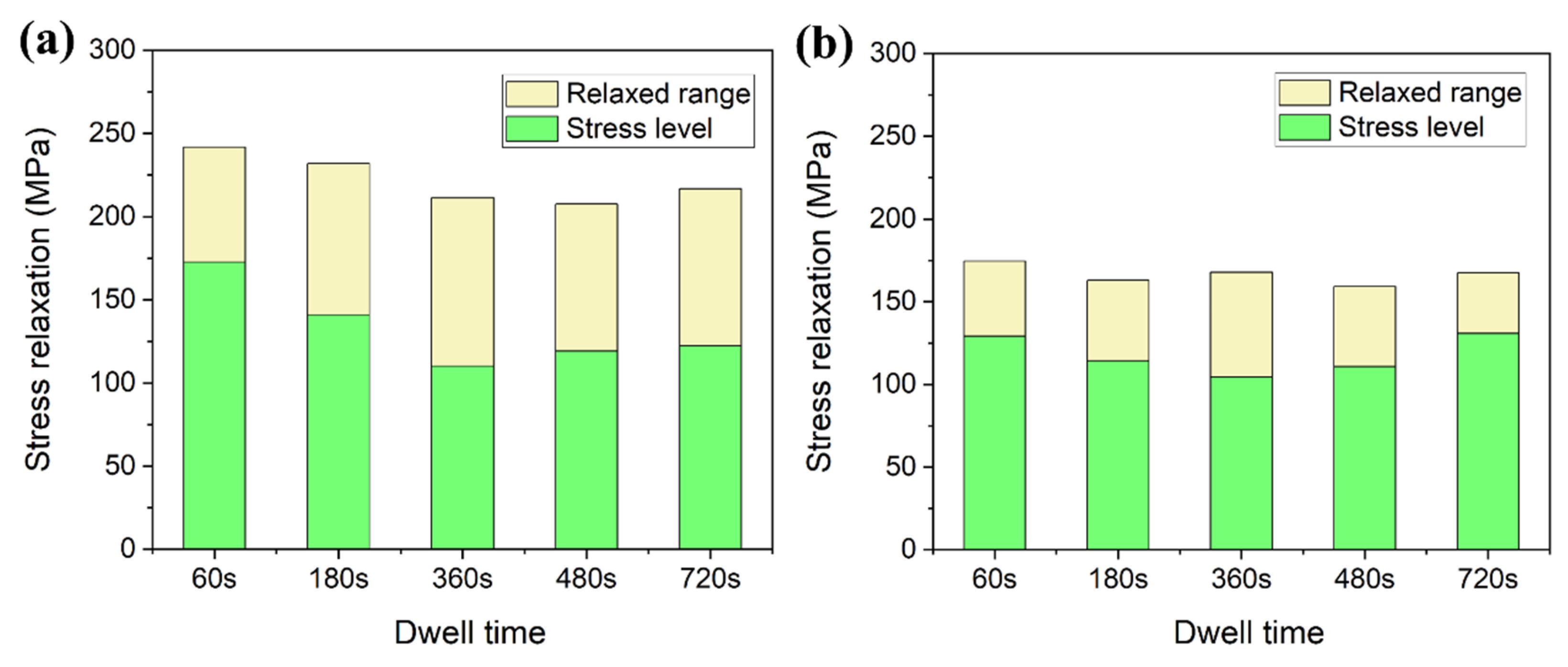
To more intuitively describe the stress relaxation behavior in the creep-fatigue experiment, the magnitudes of stress relaxation for specimens subjected to various dwell times at both the initial and half-life cycles are presented in Figure 6. Irrespective of the dwell time, the magnitude of stress relaxation in P92 steel welded joints gradually diminishes throughout the entire creep-fatigue. The reduction in the magnitude of stress relaxation becomes more pronounced with increasing dwell time. However, at the same cycle number, the stress relaxation magnitude first increases and then decreases as the dwell time increases. The maximum stress relaxation amplitude is observed at a dwell time of 360 s, which contrasts with the experimental findings for the P92 steel base metal. On the one hand, this can be attributed to the absence of a distinct tertiary stage in specimens subjected to prolonged dwell times (Figure 3), which leads to lower values derived at the half-life cycle. On the other hand, it may stem from the shift in the fracture location from the BM region to the CGHAZ region as the dwell period is extended.
Figure 6.
Variations in stress level and stress relaxation range at the first cycle (a) and the half-life cycle (b) under different dwell times.
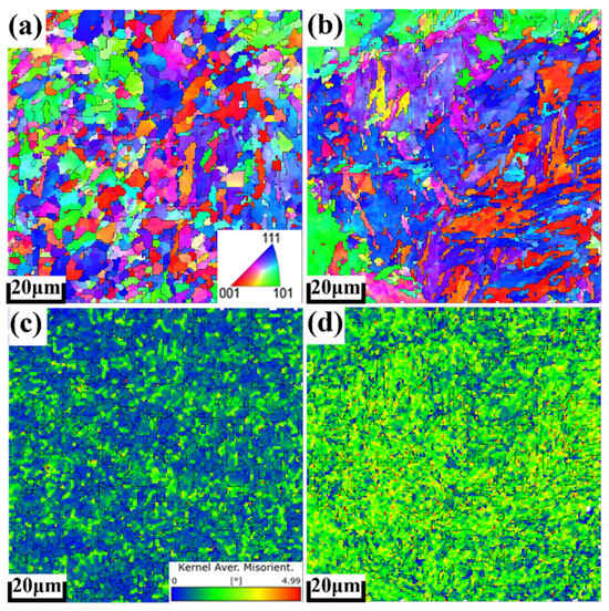
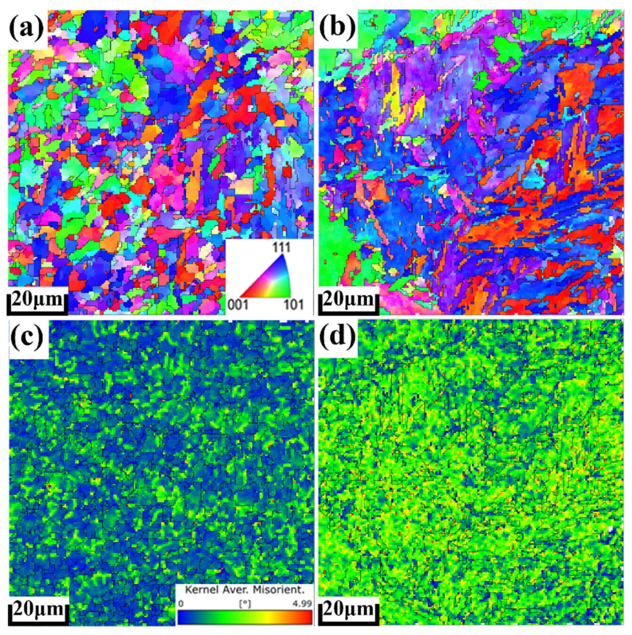
It is widely accepted that the HAZ represents the most vulnerable and crack-prone region of a welded joint due to over-tempering during welding [37,38]. In the present study, however, specimens subjected to short dwell times were observed to fail in the BM region, whereas those subjected to prolonged dwell times fractured within the CGHAZ region. Figure 7 and Figure 8 show the IPF and KAM maps near the fracture regions for the 60 s and 720 s dwell time specimens, respectively. Figure 7a shows that the FGHAZ region has a relatively small grain and subgrain structure, with a grain size similar to that of the as-received specimen. Figure 7b shows that the BM region retains the typical tempered martensite lath characteristics, but there is a certain degree of deformation inside the lath blocks. The KAM maps confirm that there is a large amount of plastic deformation in the BM region, which is much higher than that in the FGHAZ. Under short hold time conditions, because the yield strength of the BM is usually lower than that of the heat-affected zone, macroscopic plastic deformation is mainly concentrated in the softest BM region. High-density dislocations multiply and pile up extensively at the martensite lath boundaries and prior austenite grain boundaries in the BM region, leading to severe strain localization. This ultimately triggers the nucleation and propagation of microcracks, causing the specimen to fracture in the BM region. Other studies have also suggested that during cyclic loading, the deformation of the HAZ region is geometrically constrained by the adjacent regions (i.e., the BM and WM regions) [36]. As the cycling progresses, this constraint causes the strain concentration to gradually shift from the HAZ region to the base metal region.
Figure 7.
IPF maps of the FGHAZ (a) and BM (b) regions and KAM maps of the FGHAZ (c) and BM (d) regions for the short-dwell-time (60 s) specimen.
Figure 8.
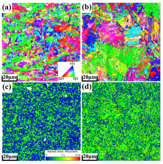
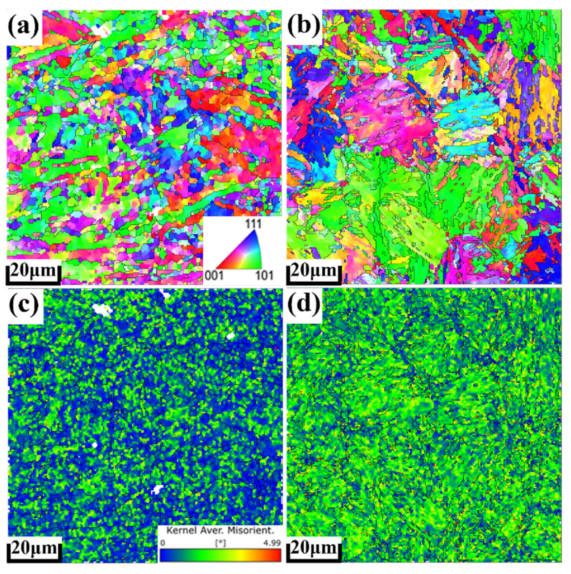
IPF maps of the FGHAZ (a) and CGHAZ (b) regions and KAM maps of the FGHAZ (c) and CGHAZ (d) regions for the long-dwell-time (720 s) specimen.
Figure 8a,b indicate that under long hold time conditions, the FGHAZ still exhibits fine grains, while the CGHAZ shows obviously coarse prior austenite grains. Under long high-temperature hold times, the microstructure of the CGHAZ may have undergone recovery, and the martensite lath boundaries become blurred. The KAM maps also confirm the presence of high-density dislocations near the austenite grain boundaries and martensite lath boundaries in the coarse-grained region. Under long hold time conditions, the fracture mechanism has changed. Because of the coarse grains in the CGHAZ, grain boundary sliding is prone to occur under high temperatures and long hold times. Furthermore, this region may be accompanied by the coarsening of precipitates (such as Laves phase or carbides), leading to strength weakening near the grain boundaries (i.e., an area prone to “creep cavities”) [39]. The continuous accumulation of this severe local creep damage eventually causes the fracture location to shift to the CGHAZ.
3.2. Nanoindentation Characterization
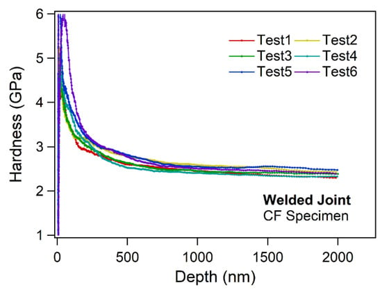
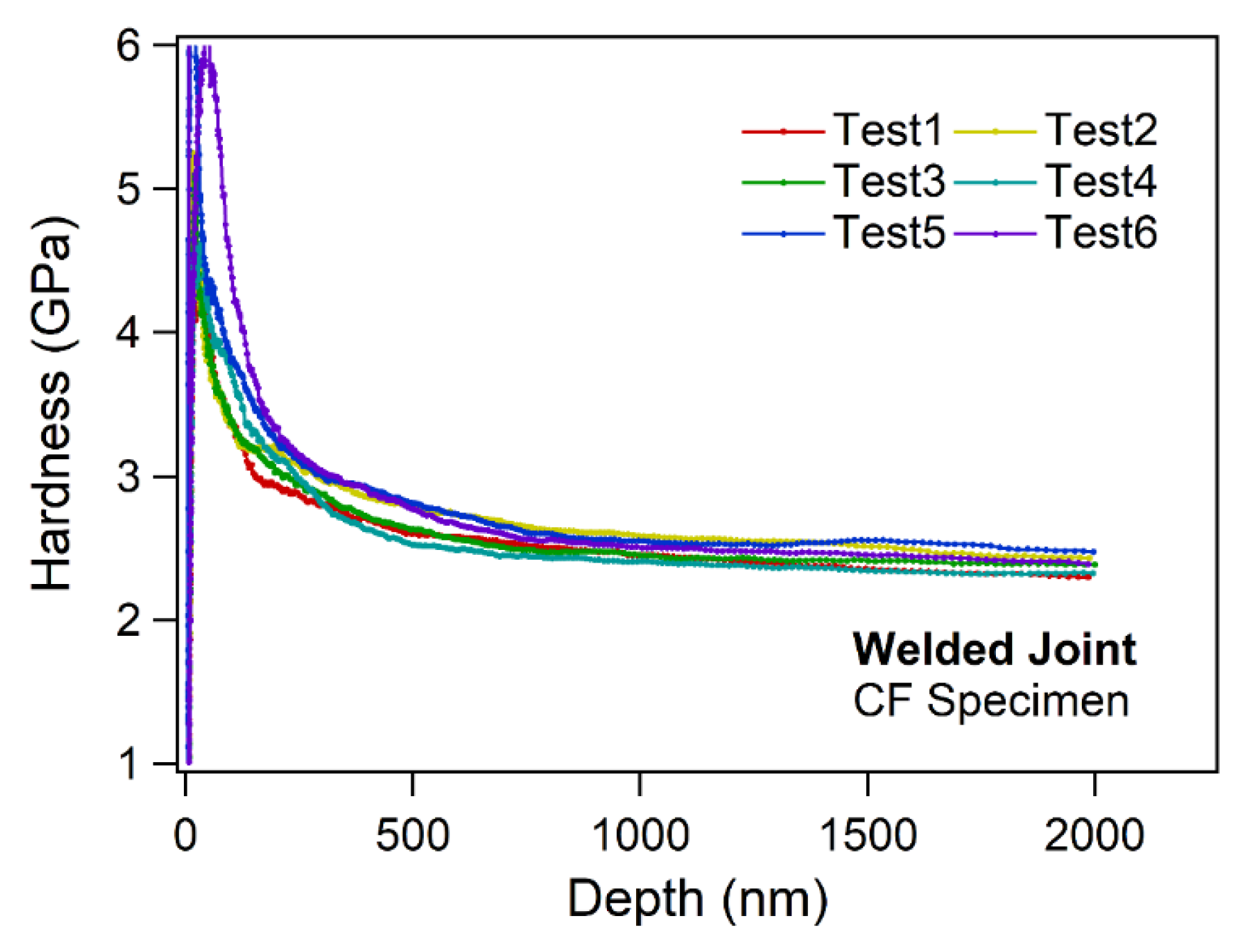
Figure 9 shows the H as a function of indentation depth, measured in the fracture edge of the P92 steel welded joints specimen after creep-fatigue. Hardness drops dramatically with increasing indentation depth. Once the depth surpasses ~500 nm, this effect becomes negligible, and the hardness plateaus at a stable value of ~2.5 GPa. A comparable ISE is also observed in the elastic modulus results. To circumvent this effect, the average values of hardness and elastic modulus obtained within the depth range of 1000 to 1500 nm were utilized.
Figure 9.
The typical hardness as a function of indentation depth, assessed by the CSM technique, in the fracture edge of the P92 steel welded joints specimen.
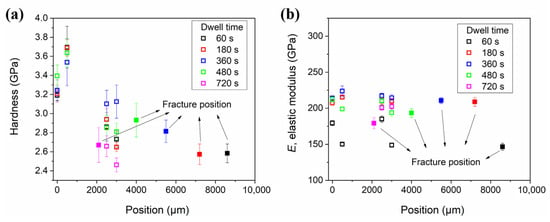
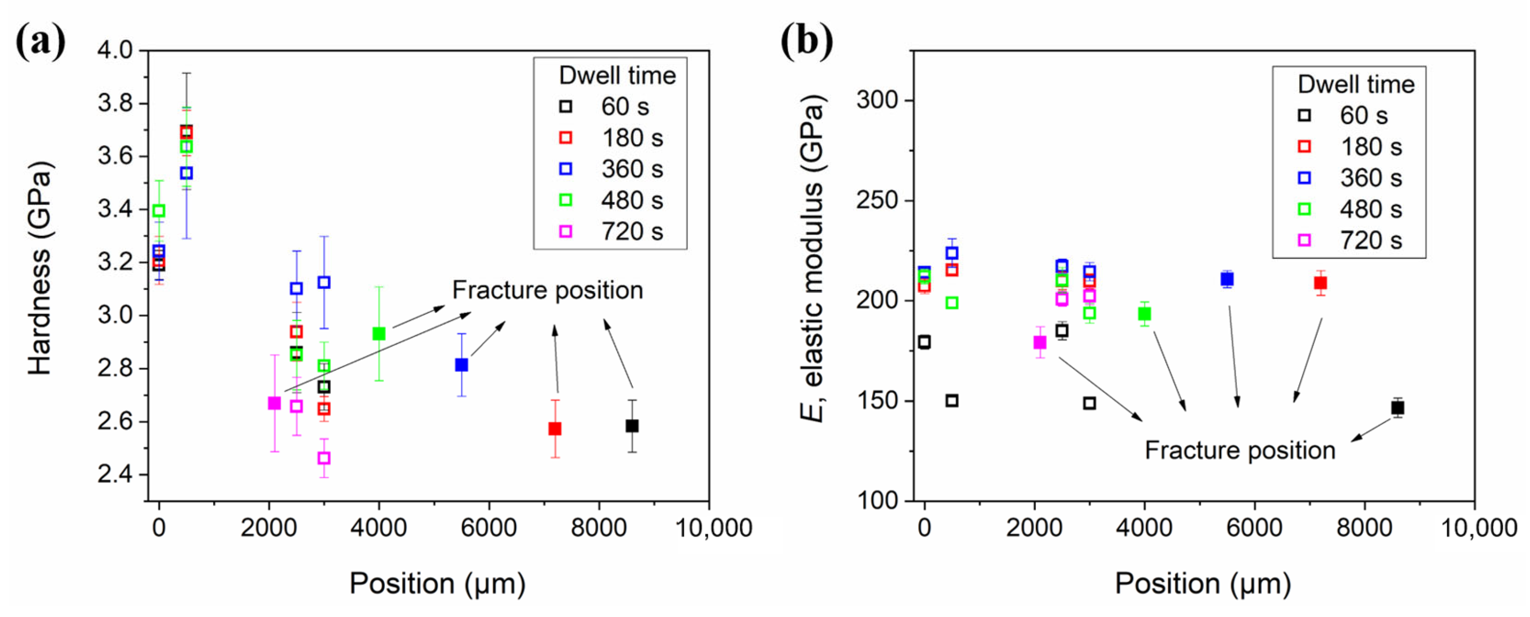
Figure 10 illustrates the hardness and elastic modulus of the creep-fatigue specimens under different dwell times. The zero position denotes the weld center, with larger values indicating closer proximity to the BM region. This visually demonstrates the progressive shift of the fracture location from the BM region towards the FGHAZ and CGHAZ regions as the dwell period is extended. The nanoindentation results in Figure 10 reveal the spatial heterogeneity of the mechanical properties across the P92 steel welded joint. The WM region exhibits the highest hardness, which gradually decreases as the indentation position approaches the BM region. The elastic moduli of the specimens under different dwell times are basically consistent, except that the elastic modulus under the 60 s dwell time is significantly lower. This reflects the damage caused by fatigue loading to the local mechanical properties of the material. As observed in Figure 10a, excluding the 720 s dwell time, the hardness at the fracture location progressively increases with prolonged dwell times. This is primarily attributed to the transition of the fracture location from the BM region to the FGHAZ region, where the refined grain size significantly enhances the hardness. Furthermore, EBSD analysis reveals a high dislocation density in the fractured region, which may also contribute to the localized hardening. Conversely, the pronounced drop in hardness for the 720 s dwell time specimen stems from the further shift of the fracture location from the FGHAZ region into the CGHAZ region, where the coarser grain size leads to softening. Additionally, the presence of abundant creep voids in the fracture zone inevitably compromises the hardness measurements. As depicted in Figure 10b, with the exception of the 60 s dwell time, the elastic modulus at the fracture location progressively decreases as the dwell period is extended. This indicates that the creep damage sustained by the material indeed leads to a degradation of local mechanical properties with prolonged dwell times. It suggests a transition in the damage mechanism from a fatigue-dominated mode to a creep-fatigue interaction regime as the dwell time increases. Under short dwell times, the overall deformation is dominated by the BM region with lower macroscopic strength. However, as the dwell time increases, the creep-fatigue interaction intensifies. Due to its inherent microstructural instability (such as precipitate coarsening and dislocation recovery), the HAZ region experiences severe local softening and damage accumulation, ultimately becoming the weak link for fracture under long dwell times [40].
Figure 10.
Hardness (a) and elastic modulus (b) of the creep-fatigue specimens under different dwell times.
3.3. Nanoindentation Creep
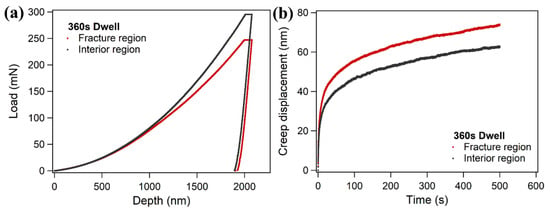
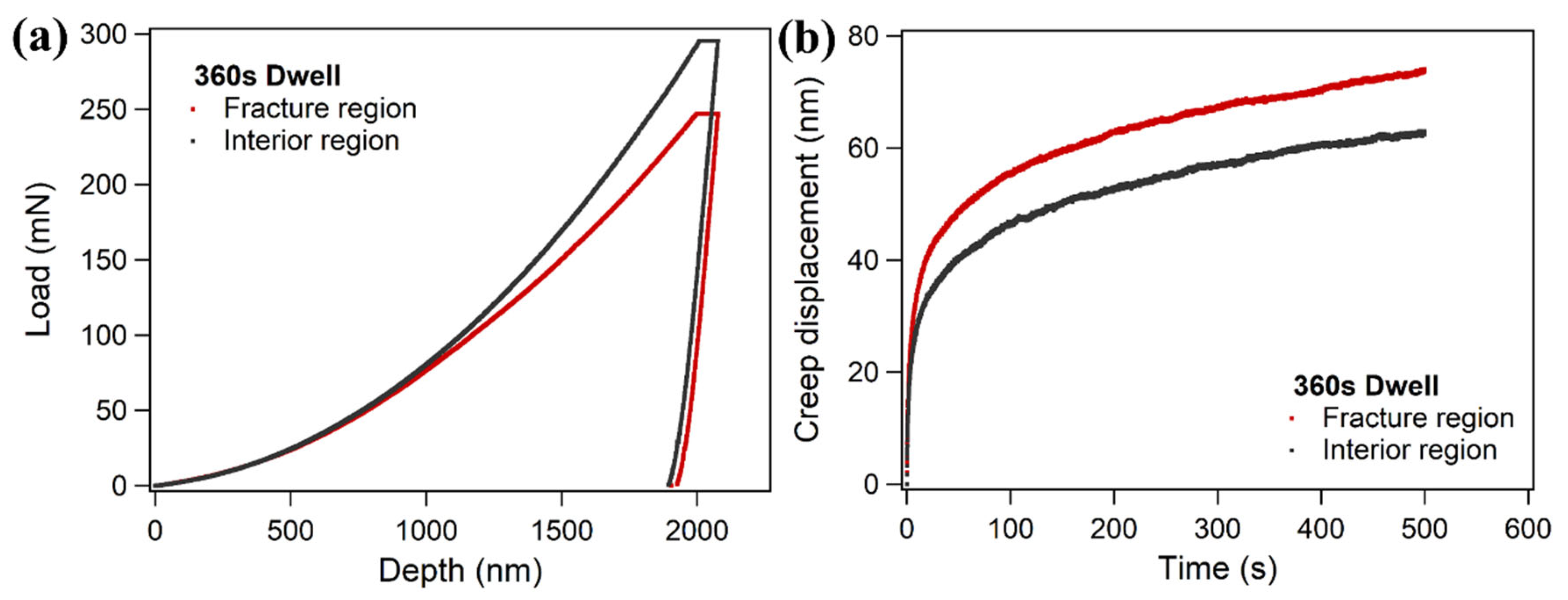
Figure 11a illustrates the typical load−displacement curves obtained from the fracture and interior regions of the 360 s dwell-time creep-fatigue specimen. The corresponding nanoindentation creep curves are presented in Figure 11b, with the initial creep displacement and dwell time both shifted to zero. It is clearly evident that the creep deformation comprises two distinct stages: primary creep and steady-state creep. During the primary stage, deformation accumulates rapidly, accompanied by a sharp decline in the creep rate. In the steady-state stage, the deformation exhibits an almost linear relationship with time, maintaining a constant creep rate. At the predetermined hold depth, the load required for the interior region of the specimen is markedly higher than that for the fracture region, whereas the resulting creep displacement is correspondingly lower. This demonstrates a significantly degraded creep resistance within the fracture region. This is primarily attributed to the fact that, under prolonged creep-fatigue interaction, the vicinity of the fracture site undergoes more severe damage accumulation and microstructural degradation. For instance, this region likely experiences more drastic dislocation recovery and annihilation, the coarsening of martensite laths and subgrains, or the nucleation and growth of microcavities and microcracks. The synergistic evolution of these micro-defects collectively dictates the deterioration of macroscopic mechanical properties within the fracture zone. The KAM maps of the fracture region confirm the presence of high-density dislocations.
Figure 11.
Representative load-depth curves (a) and creep curves (b) in fracture and interior regions for the CF specimen with a 360 s dwell time.
The mechanism of indentation deformation can be revealed by the value of strain rate SRS (m) [25,41]. In this paper, the following simplified method was used to estimate the value of m [42]:
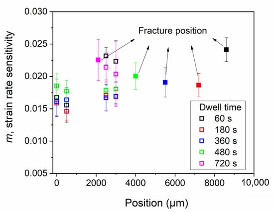
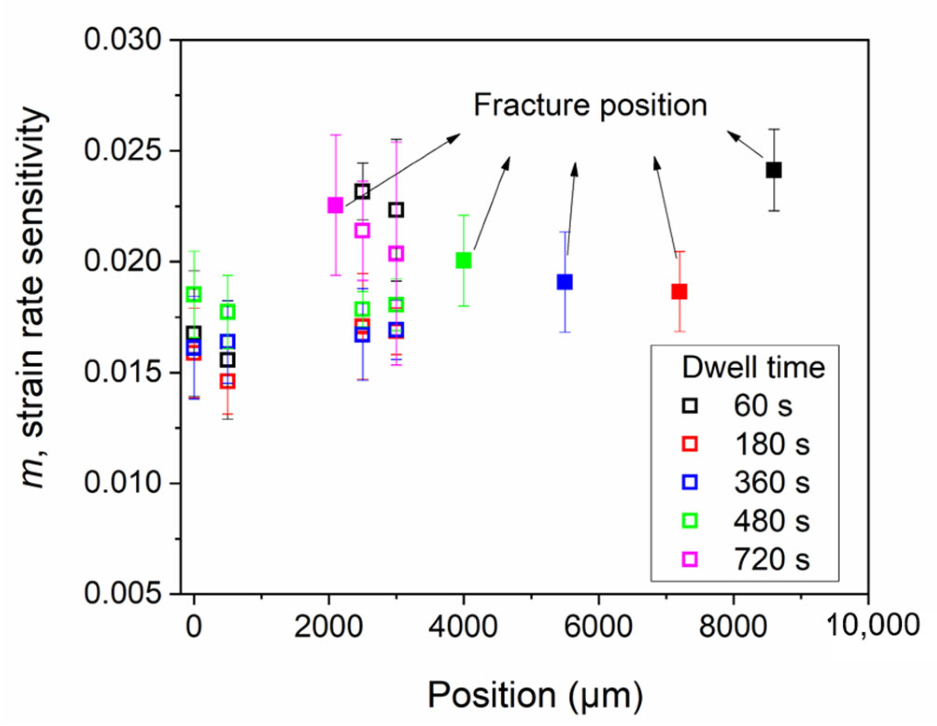
where t1 and t2 are the time at the beginning and end of the holding period during the holding stage, respectively; the parameters h1 and h2 are the corresponding displacements at the time of t1 and t2, Δhcreep is the creep displacement in the creep time interval [t1, t2], and the Δtcreep is the certain creep time. From Equation (1), the average value of m with a certain time interval [t1, t2] could be estimated. Since the creep displacement at the primary creep stage can be slightly affected by the indenter overshoot, the m should be estimated at the secondary creep stage. Figure 12 shows the distribution of SRS (m) at different positions of the welded specimens under different dwell times. In the WM region far from the fracture location, the m value is in the range of 0.015 to 0.020, and the maximum value appears at the 480 s dwell time. In the vicinity of the fracture region, the m value increases to varying degrees. This is primarily attributed to the elevated dislocation density within the fracture region [3]. As the dwell time increases, the m value at the fracture location first decreases and then increases. The m value is closely related to the thermal activation energy of dislocations, which can be defined as follows [43]:
where kb is the Boltzmann constant, T is the absolute temperature, v∗ is the thermal activation volume for dislocation nucleation, and τ is the shear stress. In this work, the m value is always in the range of 0.015 to 0.025, which indicates that the inelastic deformation mechanism of the specimens before and after creep damage is always dominated by dislocation motion.
Figure 12.
Strain rate sensitivity (SRS, m) of the creep-fatigue specimens under different dwell times.
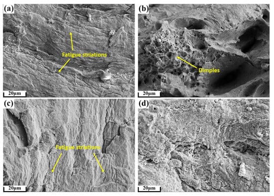
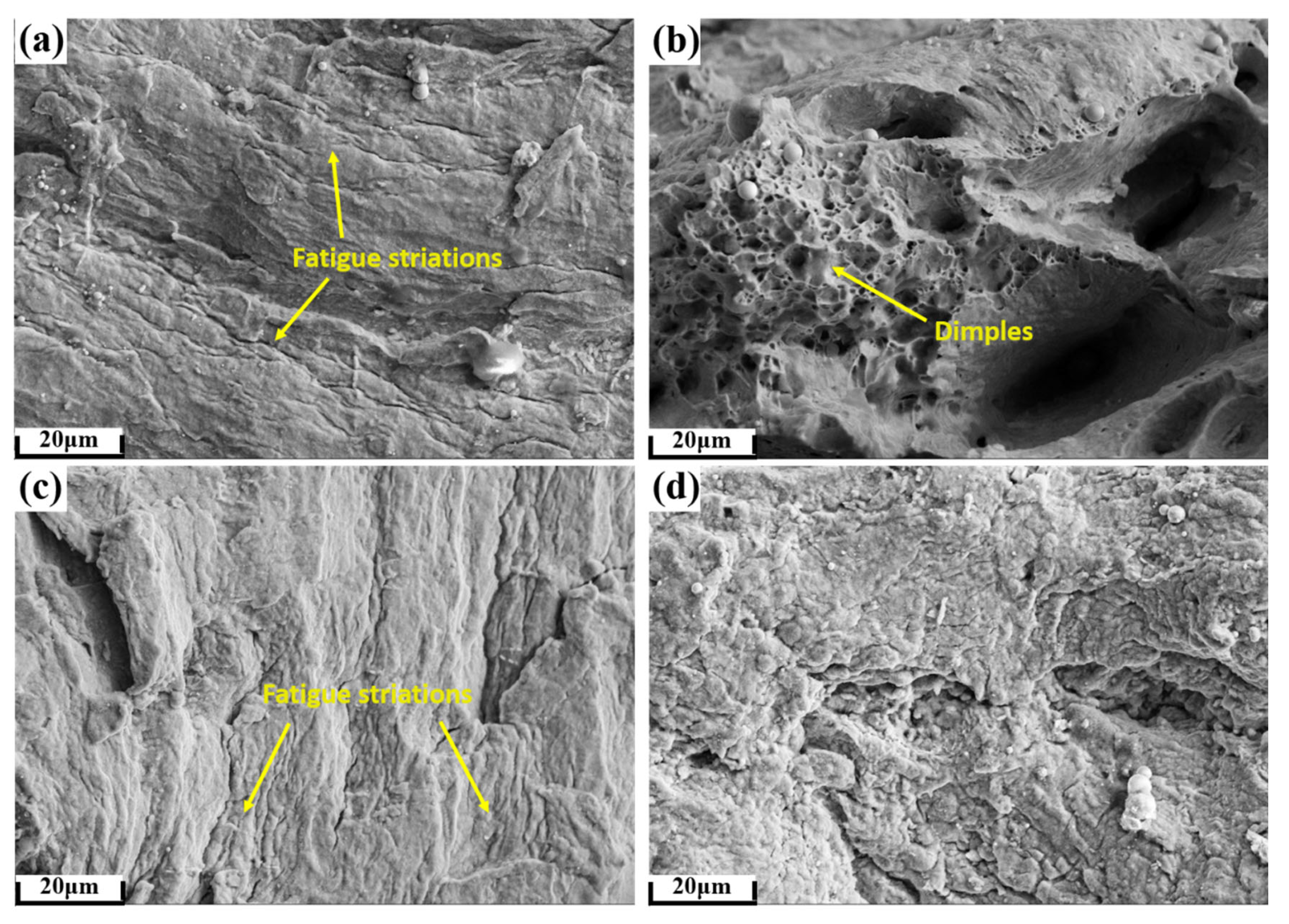
The fracture morphologies of the P92 steel welded joint CF specimens subjected to various dwell times were characterized using SEM. Since no obvious oxide layer structure was observed on the specimen surface, this paper does not extensively discuss the effect of the oxide layer on the creep-fatigue results. Localized high-magnification images reveal that for the specimen with a short dwell time of 60 s, fatigue striations are distinctly visible in the crack propagation region (Figure 13a), whereas abundant dimples are present in the ductile fracture zone (Figure 13b). As the dwell time is extended to 360 s, the fatigue striations on the fracture surface become blurred (Figure 13c). By contrast, when the dwell time is further prolonged to 720 s, not only does the fracture exhibit macroscopic necking, but the fatigue striations also become entirely imperceptible (Figure 13d). These observations indicate that more severe inelastic deformation accumulates in the P92 steel CF specimens under prolonged dwell conditions. Furthermore, the fractographic evidence substantiates an evolution in the fracture-controlling mechanism with increasing tensile dwell time, namely, a transition from a fatigue-dominated failure mode to one governed predominantly by creep-fatigue interaction damage.
Figure 13.
Fracture morphologies of the CF specimens subjected to various dwell times: (a,b) 60 s; (c) 360 s; and (d) 720 s.
4. Conclusions
This study aims to experimentally characterize the creep-fatigue fracture mechanisms of P92 steel welded joints under different dwell times. To achieve this goal, the hardness and elastic modulus of the creep-fatigue test specimen regions and the welded regions were measured. In addition, the SRS (m) of all regions was estimated based on the nanoindentation creep test results. Based on the present study, the following conclusions can be drawn:
- (1)
- The cycle life of the specimens is progressively reduced as the dwell time is extended from 60 s to 720 s. The increase in dwell time also alters the preferential damage location of the welded joint. Crack initiation consistently occurs in the BM region under short dwell conditions, and the initiation site gradually shifts from the FGHAZ region to CGHAZ region with pro-longed dwell times.
- (2)
- With the increase in dwell time, the disappearance of the third stage in the peak tensile stress−cycle curve and the absence of fatigue striations on the fracture surface indicate that fatigue crack propagation no longer plays a dominant role. This demonstrates that the fracture mechanism transitions from fatigue damage to creep-fatigue interaction damage.
- (3)
- Nanoindentation tests reveal that creep damage induces a deterioration in local mechanical properties as the hold time increases. The strain rate sensitivity of the block grains in specimens with different dwell times ranges from 0.015 to 0.025, indicating that the inelastic deformation mechanism is primarily dominated by dislocation motion within the dwell time range selected in this study. Furthermore, the KAM results confirm a positive correlation between the accumulation of inelastic deformation and the increase in dislocation density.
Author Contributions
Y.S. (Yini She), methodology, writing—original draft preparation and funding acquisition; Z.W., data curation, investigation, conceptualization, formal analysis, and supervision; L.Z., conceptualization and writing—review and editing, validation and visualization; Z.S., resources and visualization; L.R.: methodology, project administration, and software; Y.S. (Yuxuan Song), formal analysis, software, and supervision. All authors have read and agreed to the published version of the manuscript.
Funding
This research was funded by “Zhejiang Provincial Market Supervision and Administration Bureau Key Project, grant number ZD2025018”, “Zhejiang Provincial Administration for Market Regulation Science and Technology Program, grant number ZC2026003”, and “the National Natural Science Foundation of China, grant number 52305168”.
Data Availability Statement
The original contributions presented in this study are included in the article. Further inquiries can be directed to the corresponding author.
Acknowledgments
Yixi Wang is thanked for the help in the SEM and EBSD characterizations.
Conflicts of Interest
Author Zhibin Shen was employed by Wenzhou Special Equipment Inspection & Science Research Institute, and author Licheng Ruan was employed by Ningbo Special Equipment Inspection and Research Institute. The remaining authors declare that the research was conducted in the absence of any commercial or financial relationships that could be construed as a potential conflict of interest.
Abbreviations
| USC | ultra-supercritical |
| GTAW | gas tungsten arc welding |
| SAW | submerged arc welding |
| EDM | electro-discharge machining |
| SEM | scanning electron microscopy |
| EBSD | electron backscatter diffraction |
| XRD | X-ray diffraction |
| IPF | inverse pole figure |
| KAM | kernel Average Misorientation |
| SRS (m) | strain rate sensitivity |
| HABGs | high-angle grain boundaries |
| CF | creep-fatigue |
| BM | base material |
| HAZ | heat-affected zone |
| FGHAZ | fine-grained heat-affected zone |
| CGHAZ | coarse-grained heat affected zone |
| WM | weld metal |
| CSM | continuous stiffness measurement |
| DSA | dynamic strain aging |
| ISE | indentation size effect |
| H | hardness |
| E | elastic modulus |
| GND | geometrically necessary dislocation |
References
- Susmel, L.; Taylor, D. Two methods for predicting the multiaxial fatigue limits of sharp notches. Fatigue Fract. Eng. Mater. Struct. 2003, 26, 821–833. [Google Scholar] [CrossRef] [Scilit]
- Wang, Y.; Qin, N.; Shang, J.; Yang, J.; Sun, B. Study on Microstructure and Properties of P92 Steel Joint with Narrow Gap Automatic Welding. J. Phys. Conf. Ser. 2023, 2549, 012009. [Google Scholar] [CrossRef] [Scilit]
- Song, Y.; Pan, Z.; Chen, J.; Qin, F.; Gao, Z.; Zhang, T.; Ma, Y. The effects of prior creep–fatigue on the strain rate sensitivity of a P92 welded joint. J. Mater. Sci. 2021, 56, 7111–7128. [Google Scholar] [CrossRef] [Scilit]
- Zhang, S.-L.; Xuan, F.-Z. Interaction of cyclic softening and stress relaxation of 9–12% Cr steel under strain-controlled fatigue-creep condition: Experimental and modeling. Int. J. Plast. 2017, 98, 45–64. [Google Scholar] [CrossRef] [Scilit]
- Zhang, W.; Wang, X.; Kang, Z.; Zhang, T.; Jiang, Y.; Zhang, X.; Gong, J. Characterization of the cyclic softening and remaining creep behaviour of P92 steel weldment. J. Mater. Res. Technol. 2021, 15, 1446–1456. [Google Scholar] [CrossRef] [Scilit]
- Zhang, S.-L.; Xuan, F.-Z.; Guo, S.-J.; Zhao, P. The role of anelastic recovery in the creep-fatigue interaction of 9–12% Cr steel at high temperature. Int. J. Mech. Sci. 2017, 122, 95–103. [Google Scholar] [CrossRef] [Scilit]
- Manugula, V.L.; Rajulapati, K.V.; Reddy, G.M.; Rao, K.B.S. Role of evolving microstructure on the mechanical properties of electron beam welded ferritic-martensitic steel in the as-welded and post weld heat-treated states. Mater. Sci. Eng. A 2017, 698, 36–45. [Google Scholar] [CrossRef] [Scilit]
- Pandey, C.; Mahapatra, M.M.; Kumar, P.; Thakre, J.G.; Saini, N. Role of evolving microstructure on the mechanical behaviour of P92 steel welded joint in as-welded and post weld heat treated state. J. Mater. Process. Technol. 2019, 263, 241–255. [Google Scholar] [CrossRef] [Scilit]
- Francis, J.A.; Mazur, W.; Bhadeshia, H.K.D.H. Review Type IV cracking in ferritic power plant steels. Mater. Sci. Technol. 2006, 22, 1387–1395. [Google Scholar] [CrossRef] [Scilit]
- Matsui, M.; Tabuchi, M.; Watanabe, T.; Kubo, K.; Kinugawa, J.; Abe, F. Degradation of Creep Strength in Welded Joint of 9%Cr Steel. ISIJ Int. 2001, 41, S126–S130. [Google Scholar] [CrossRef] [Scilit] [PubMed]
- Tabuchi, M.; Watanabe, T.; Kubo, K.; Matsui, M.; Kinugawa, J.; Abe, F. Creep crack growth behavior in the HAZ of weldments of W containing high Cr steel. Int. J. Press. Vessel. Pip. 2001, 78, 779–784. [Google Scholar] [CrossRef] [Scilit]
- Pandey, C.; Mahapatra, M.M.; Kumar, P.; Kumar, S.; Sirohi, S. Effect of post weld heat treatments on microstructure evolution and type IV cracking behavior of the P91 steel welds joint. J. Mater. Process. Technol. 2019, 266, 140–154. [Google Scholar] [CrossRef] [Scilit]
- Falat, L.; Výrostková, A.; Homolová, V.; Svoboda, M. Creep deformation and failure of E911/E911 and P92/P92 similar weld-joints. Eng. Fail. Anal. 2009, 16, 2114–2120. [Google Scholar] [CrossRef] [Scilit]
- Abe, F.; Tabuchi, M.; Kondo, M.; Tsukamoto, S. Suppression of Type IV fracture and improvement of creep strength of 9Cr steel welded joints by boron addition. Int. J. Press. Vessel. Pip. 2007, 84, 44–52. [Google Scholar] [CrossRef] [Scilit]
- Barrett, R.A.; O’Donoghue, P.E.; Leen, S.B. A physically-based constitutive model for high temperature microstructural degradation under cyclic deformation. Int. J. Fatigue 2017, 100, 388–406. [Google Scholar] [CrossRef] [Scilit]
- Jeong, C.Y.; Bae, J.-C.; Kang, C.-S.; Cho, J.-I.; Son, H.-T. Normalized creep–fatigue life prediction model based on the energy dissipation during hold time. Mater. Sci. Eng. A 2007, 460–461, 195–203. [Google Scholar] [CrossRef] [Scilit]
- Wang, Q.; Xu, Z.; Wang, X. An efficient fatigue and creep-fatigue life prediction method by using the hysteresis energy density rate concept. Fatigue Fract. Eng. Mater. Struct. 2020, 43, 1529–1540. [Google Scholar] [CrossRef] [Scilit]
- Fischer, T.; Kuhn, B. Impact of frequency, hold time and atmosphere on creep-fatigue of a 9–12% Cr steel from 300–600 °C. Int. J. Fatigue 2019, 124, 288–302. [Google Scholar] [CrossRef] [Scilit]
- Wang, R.-Z.; Zhu, X.-M.; Zhang, X.-C.; Tu, S.-T.; Gong, J.-G.; Zhang, C.-C. A generalized strain energy density exhaustion model allowing for compressive hold effect. Int. J. Fatigue 2017, 104, 61–71. [Google Scholar] [CrossRef] [Scilit]
- Wang, R.-Z.; Zhang, X.-C.; Tu, S.-T.; Zhu, S.-P.; Zhang, C.-C. A modified strain energy density exhaustion model for creep–fatigue life prediction. Int. J. Fatigue 2016, 90, 12–22. [Google Scholar] [CrossRef] [Scilit]
- Li, C.; Zhao, L.; Xu, L.; Han, Y.; Hao, K. Insights on microstructure evolution of austenite welded joints subjected to creep-fatigue loading. J. Mater. Res. Technol. 2024, 30, 8635–8647. [Google Scholar] [CrossRef] [Scilit]
- Ando, M.; Takaya, S. Creep–fatigue evaluation method for weld joints of Mod.9Cr–1Mo steel. Part I: Proposal of the evaluation method based on finite element analysis and uniaxial testing. Nucl. Eng. Des. 2017, 323, 463–473. [Google Scholar] [CrossRef] [Scilit]
- Ando, M.; Takaya, S. Creep-fatigue evaluation method for weld joint of Mod.9Cr-1Mo steel Part II: Plate bending test and proposal of a simplified evaluation method. Nucl. Eng. Des. 2016, 310, 217–230. [Google Scholar] [CrossRef] [Scilit]
- Song, Y.; Yu, T.; Chen, H.; Jin, W.; Gao, Z.; Debela, T.T.; Wu, Z.; Ma, Y. Understanding the relation between creep-fatigue fracture mechanisms and intergranular dislocation accommodation of a high chromium steel using nanoindentation characterization. Int. J. Fatigue 2022, 159, 106796. [Google Scholar] [CrossRef] [Scilit]
- Ma, Y.; Peng, G.J.; Wen, D.H.; Zhang, T.H. Nanoindentation creep behavior in a CoCrFeCuNi high-entropy alloy film with two different structure states. Mater. Sci. Eng. A 2015, 621, 111–117. [Google Scholar] [CrossRef] [Scilit]
- ASTM SA-335/335M-24; Specification for Seamless Ferritic Alloy-Steel Pipe for High-Temperature Service. American Society for Testing and Materials: West Conshohocken, PA, USA, 2024.
- Oliver, W.C.; Pharr, G.M. Measurement of hardness and elastic modulus by instrumented indentation: Advances in understanding and refinements to methodology. J. Mater. Res. 2004, 19, 3–20. [Google Scholar] [CrossRef]
- Song, Y.; Pan, Z.; Yu, T.; Zhou, S.; Li, Y.; Jin, W.; Gao, Z.; Ma, Y. Nanoindentation characterization on competing propagation between the transgranular and intergranular cracking of 316H steel under creep-fatigue loading. Fatigue Fract. Eng. Mater. Struct. 2023, 46, 2258–2271. [Google Scholar] [CrossRef] [Scilit]
- Wang, H.; Xu, W.; Wang, Y.; Lu, H. Creep-fatigue behavior of a friction stir welding 7050-T7451 aluminum alloy: Microstructure evolution and microscopic damage mechanisms. Int. J. Fatigue 2025, 194, 108840. [Google Scholar] [CrossRef] [Scilit]
- Wang, X.; Zhang, W.; Gong, J.; Jiang, Y. Experimental and numerical characterization of low cycle fatigue and creep fatigue behaviour of P92 steel welded joint. Fatigue Fract. Eng. Mater. Struct. 2018, 41, 611–624. [Google Scholar] [CrossRef] [Scilit]
- Veerababu, J.; Goyal, S.; Sandhya, R.; Laha, K. Low cycle fatigue behaviour of Grade 92 steel weld joints. Int. J. Fatigue 2017, 105, 60–70. [Google Scholar] [CrossRef] [Scilit]
- Fournier, B.; Dalle, F.; Sauzay, M.; Longour, J.; Salvi, M.; Caës, C.; Tournié, I.; Giroux, P.-F.; Kim, S.-H. Comparison of various 9–12%Cr steels under fatigue and creep-fatigue loadings at high temperature. Mater. Sci. Eng. A 2011, 528, 6934–6945. [Google Scholar] [CrossRef] [Scilit]
- Giroux, P.F.; Dalle, F.; Sauzay, M.; Caës, C.; Fournier, B.; Morgeneyer, T.; Gourgues-Lorenzon, A. Influence of strain rate on P92 microstructural stability during fatigue tests at high temperature. Procedia Eng. 2010, 2, 2141–2150. [Google Scholar] [CrossRef] [Scilit]
- Nagesha, A.; Valsan, M.; Kannan, R.; Rao, K.B.S.; Mannan, S.L. Influence of temperature on the low cycle fatigue behaviour of a modified 9Cr–1Mo ferritic steel. Int. J. Fatigue 2002, 24, 1285–1293. [Google Scholar] [CrossRef] [Scilit]
- Shankar, V.; Sandhya, R.; Mathew, M.D. Creep–fatigue-oxidation interaction in Grade 91 steel weld joints for high temperature applications. Mater. Sci. Eng. A 2011, 528, 8428–8437. [Google Scholar] [CrossRef] [Scilit]
- Veerababu, J.; Goyal, S.; Sandhya, R. Cyclic viscoplastic analysis for steam generator material of Indian fast breeder reactor. Fatigue Fract. Eng. Mater. Struct. 2018, 41, 2362–2375. [Google Scholar] [CrossRef] [Scilit]
- Sakthivel, T.; Vasudevan, M.; Laha, K.; Parameswaran, P.; Chandravathi, K.S.; Selvi, S.P.; Maduraimuthu, V.; Mathew, M.D. Creep rupture behavior of 9Cr–1.8W–0.5Mo–VNb (ASME grade 92) ferritic steel weld joint. Mater. Sci. Eng. A 2014, 591, 111–120. [Google Scholar] [CrossRef] [Scilit]
- Goyal, S.; Laha, K.; Chandravathi, K.S.; Parameswaran, P.; Mathew, M.D. Finite element analysis of type IV cracking in 2.25Cr–1Mo steel weldment based on micro-mechanistic approach. Philos. Mag. 2011, 91, 3128–3154. [Google Scholar] [CrossRef] [Scilit]
- Yu, T.; Wang, Z.; Lin, Y.; Cai, Z.; Song, Y.; Shen, G.; Tan, D.; Gao, Z. An experimental study on stress-dependent creep behaviors and microstructural evolutions of 316H stainless steel by nanoindentation characterization. Eng. Fail. Anal. 2026, 192, 110825. [Google Scholar] [CrossRef] [Scilit]
- Cai, L.; Zhao, L.; Song, K.; Xu, L.; Han, Y.; Hao, K.; Wang, Q.; Guo, D. Microstructural evolution, creep damage mechanism and failure risk of P92 steel welded joints after long-term service. Int. J. Press. Vessel. Pip. 2026, 219, 105677. [Google Scholar] [CrossRef] [Scilit]
- Ma, Y.; Peng, G.J.; Debela, T.T.; Zhang, T.H. Nanoindentation study on the characteristic of shear transformation zone volume in metallic glassy films. Scr. Mater. 2015, 108, 52–55. [Google Scholar] [CrossRef] [Scilit]
- Song, Y.; Qin, F.; Chen, J.; Pan, Z.; Huang, X.; Ding, Z.; Gao, Z.; Zhang, T.; Ma, Y. On the microstructural evolution and room-temperature creep behaviour of 9%Cr steel weld joint under prior creep–fatigue interaction. Fatigue Fract. Eng. Mater. Struct. 2021, 44, 444–460. [Google Scholar] [CrossRef] [Scilit]
- Wei, Q.; Cheng, S.; Ramesh, K.T.; Ma, E. Effect of nanocrystalline and ultrafine grain sizes on the strain rate sensitivity and activation volume: Fcc versus bcc metals. Mater. Sci. Eng. A 2004, 381, 71–79. [Google Scholar] [CrossRef] [Scilit]

Disclaimer/Publisher’s Note: The statements, opinions and data contained in all publications are solely those of the individual author(s) and contributor(s) and not of MDPI and/or the editor(s). MDPI and/or the editor(s) disclaim responsibility for any injury to people or property resulting from any ideas, methods, instructions or products referred to in the content. |
© 2026 by the authors. Licensee MDPI, Basel, Switzerland. This article is an open access article distributed under the terms and conditions of the Creative Commons Attribution (CC BY) license.