Article

Enhanced Impact Toughness of 6082 Aluminum Alloy via Electromagnetic Shocking Treatment

1
Hubei Key Laboratory of Advanced Technology for Automobile Components, Wuhan University of Technology, Wuhan 430070, China
2
Hubei Collaborative Innovation Center for Automotive Components Technology, Wuhan University of Technology, Wuhan 430070, China
3
Hubei Research Center for New Energy & Intelligent Connected Vehicle, Wuhan University of Technology, Wuhan 430070, China
4
State Key Laboratory of Light Superalloys, Wuhan University of Technology, Wuhan 430070, China
*
Author to whom correspondence should be addressed.
Metals 2026, 16(8), 915; https://doi.org/10.3390/met16080915
Submission received: 11 July 2026 / Revised: 10 August 2026 / Accepted: 13 August 2026 / Published: 15 August 2026
(This article belongs to the Special Issue Advances in Lightweight Alloys, 3rd Edition)

Abstract

To further improve the impact toughness of aged 6082 aluminum alloy, electromagnetic shocking treatment (EST) was applied to IHC (solution treatment + unidirectional compression + peak aging) samples. The mechanical properties and impact toughness of the IHC and EST samples were evaluated through room-temperature tensile tests and Charpy impact tests, respectively. The results indicate that, compared to the IHC samples, the EST samples exhibit higher tensile strength (an increase of approximately 9.4%), greater elongation, and significantly higher impact energy (an increase of approximately 26.5%). Microstructural characterization reveals that, compared to the IHC samples, the EST samples possess a lower dislocation density, a larger grain size, and shorter precipitates. Striped grain boundaries were observed in both IHC and EST samples, but they were considerably more pronounced in the EST samples. This indicates that more distinct interface wetting occurred in the EST samples, which promoted grain growth to some extent, a reduction in dislocation density, precipitate dissolution, and the occurrence of interface bridging. This paper primarily investigates the microstructural evolution within the alloy under EST and discusses how these microstructural changes influence the alloy’s performance, thereby providing a novel approach to enhancing the impact toughness of aluminum alloys.

1. Introduction

Wrought aluminum alloys are widely utilized in the development and manufacturing of the automotive and aerospace industries due to their light weight, high specific strength, and excellent corrosion resistance. Especially in safety-critical structural components, aluminum alloy forgings play an indispensable role. For instance, 6082 aluminum alloy is extensively applied in the manufacturing of automotive chassis and steering forgings. These applications require not only good workability but also significant enhancements in service reliability through performance optimization. However, under actual service or extreme impact conditions for these critical load-bearing components, the fracture and impact toughness behavior of engineering aluminum alloys is of paramount technical significance for ensuring “fail-safe” material design in structural applications. Toughness, as a core indicator measuring a material’s ability to absorb plastic deformation energy prior to fracture, is one of the most critical mechanical properties that must be considered in structural design. Generally, the higher the strength and plasticity of an alloy, the better its comprehensive toughness [1,2,3]. But in reality, within traditional alloy strengthening paradigms (such as grain refinement, precipitation strengthening, or work hardening), the toughness of an alloy is often a compromise between strength and plasticity, which typically exhibit a mutually exclusive relationship [4,5,6].
Traditionally, to further optimize the mechanical properties of aluminum alloys, researchers have primarily relied on intrinsic toughening achieved through microstructural manipulation. For example, AmneElahi and Shabestari [7] proposed that simultaneous grain refinement and Sr modification, followed by T6 heat treatment, can effectively alter the morphology of eutectic silicon, thereby significantly enhancing the impact toughness of A356 aluminum alloy. Besides heat treatment and modification, severe plastic deformation (SPD) techniques are also widely employed for grain refinement to improve comprehensive properties. Meyer et al. [8] suggested that equal-channel angular pressing (ECAP) followed by short-term, high-temperature aging can enhance the strength, ductility, and impact toughness of 6063 aluminum alloy by inducing severe plastic strain and subsequent microstructural recovery. Similarly, Ma et al. [9] found that rotary-die equal-channel angular pressing (RD-ECAP) can fragment coarse aluminum dendrites and eutectic silicon networks, forming a uniform ultrafine-grained structure with modified grain boundaries and finely dispersed silicon particles, which significantly boosts the impact toughness of Al-11mass%Si cast aluminum alloy.
However, the potential for enhancing toughness solely by relying on intrinsic strengthening methods, such as grain refinement or optimizing internal phase distribution, is gradually reaching a bottleneck. As strength is further elevated, strain tends to localize more easily at local grain boundaries. To break through this bottleneck, researchers have begun to explore suitable extrinsic toughening mechanisms.
A common strategy is the introduction of exogenous reinforcing phases to impede crack propagation. Subramaniam et al. [10] demonstrated that incorporating boron carbide and coconut shell fly ash into the matrix via stir casting can form a robust matrix–reinforcement interface. This heterogeneous interface effectively arrests crack propagation and absorbs higher plastic deformation energy, thereby enhancing the impact toughness of 7075 aluminum alloy. In addition to introducing internal heterogeneous phases, surface engineering has also been utilized to improve localized impact protection capabilities. Hao et al. [11] employed plasma electrolytic oxidation (PEO) technology in a mixed electrolyte of phosphate and dichromate to enhance the wear and impact resistance of 6061 aluminum alloy. This mixed electrolyte can effectively suppress the outward deposition of materials during the initial reaction stage, causing the coating’s growth to rely heavily on the oxidation of the aluminum substrate itself, which significantly strengthens the physical bonding between the coating and the substrate. Furthermore, some researchers have attempted to synergize intrinsic and extrinsic mechanisms at the macroscopic scale. Cepeda-Jiménez et al. [12] processed alternating Al7075 and Al1050 multilayer aluminum laminates using a hot roll bonding process, successfully achieving a substantial improvement in impact toughness through the synergistic effect of intrinsic microstructural refinement and extrinsic crack deflection facilitated by controlled interfacial delamination.
Although the aforementioned methods involving the introduction of exogenous hard particles, surface coatings, or macroscopic multilayer structures can effectively improve the impact response of aluminum alloys, they inevitably require complex manufacturing processes, and a large number of introduced foreign interfaces often act as new initiation sites for microcracks. Therefore, how to directly reconstruct the grain boundary structure of the solid matrix itself via non-contact means without disrupting the continuity of high-strength aluminum alloys—achieving an “endogenous” extrinsic toughening without foreign phase introduction—has become a critical challenge currently in need of resolution.
Electromagnetic shocking treatment (EST), as a non-contact, external field-assisted manufacturing technology, provides a novel pathway to solve the aforementioned “endogenous” solid-state interface reconstruction problem. Studies have shown that a high-energy-density pulsed electromagnetic field can instantaneously inject intense energy into metallic materials, significantly promoting atomic diffusion, dislocation annihilation, and grain boundary migration through the strong coupling of electro-induced localized Joule heating and non-thermal effects [13,14]. Especially in regions such as grain boundaries, phase boundaries, and micro-defects, where the local electrical resistivity is much higher than that of the intra-granular matrix, the pulsed electromagnetic field triggers a severe energy concentration phenomenon. This localized energy mutation can induce cross-interface atomic oscillation, local rearrangement, and self-healing within a macroscopic low-temperature environment over an extremely short duration (typically in milliseconds), thereby realizing active reconstruction of microscopic interfaces without destroying the overall continuity of the matrix [15,16]. Compared to traditional heat treatments and severe plastic deformation techniques, electromagnetic shocking treatment can rapidly modulate the dislocation evolution and precipitate morphology of the alloy in a non-contact, physical manner [17]. This unique external field-driven microstructural evolution mechanism highlights a highly promising direction for directly achieving crack deflection and interface bridging toughening in high-strength aluminum alloys without introducing a large number of foreign interfaces.
Previous studies on 6xxx aluminum alloys have employed markedly different electropulsing parameters depending on the intended processing objective. Wang et al. applied high-energy EPT to solution-treated AA6061 at an average current density of approximately 51.5 A/mm2 for only 560 ms, resulting in simultaneous changes in strength and ductility associated with the formation of Mg–Si–Cu clusters and subgrain structures [18]. Hong et al. employed current densities of 75–90 A/mm2 with 0.5 s pulses at approximately 2 Hz during electrically assisted progressive forging of AA6061-T6, where the current was applied concurrently with deformation to improve formability and reduce the required forming load [19]. In contrast, Pan et al. used cyclic EPT on AA6061 with six pulses at approximately 86.97 A/mm2 and a reported pulse duration of 240 ms, demonstrating that cyclic current application could induce pronounced microstructural refinement even without mechanical deformation [20]. Hameed et al. employed a substantially different regime during electropulsing-assisted machining of AA6060, using much higher current densities of approximately 500–3190 A/mm2, a pulse width of about 250 μs, and a frequency of 300 Hz [21]. These comparisons demonstrate that frequency, pulse duration, waveform, number of pulses, initial material state, and treatment objective collectively determine the resulting electrical and thermal histories.
Based on an integrated solution-quenching process, this paper proposes a method utilizing electromagnetic shocking treatment to post-process compression-aged aluminum alloy, artificially promoting the occurrence of interface bridging in 6082 aluminum alloy, thereby improving its impact toughness. Additionally, the effects of EST on the microstructure and impact toughness of 6082 aluminum alloy are analyzed and discussed.

2. Materials and Methods

2.1. Experimental Materials

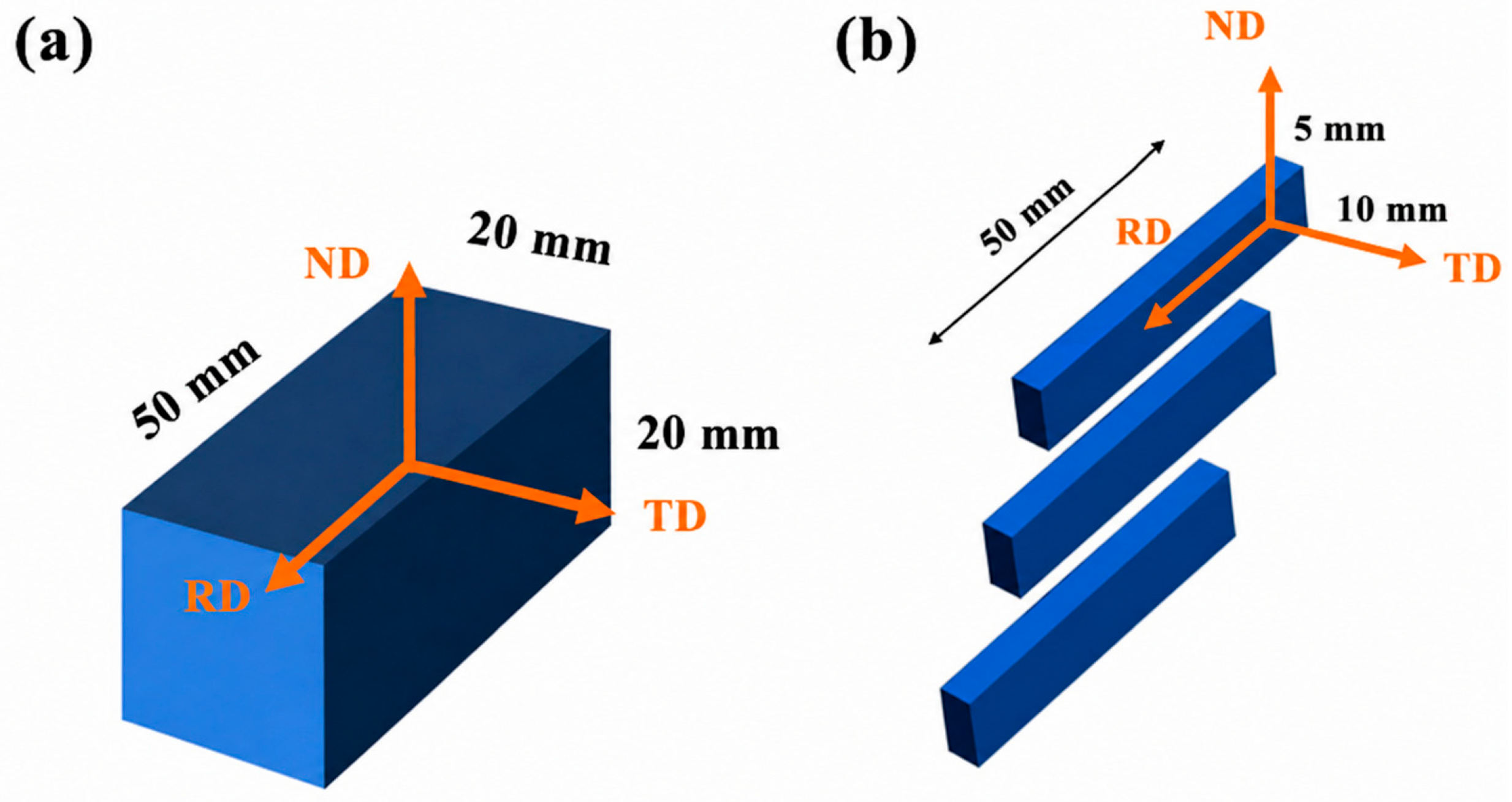
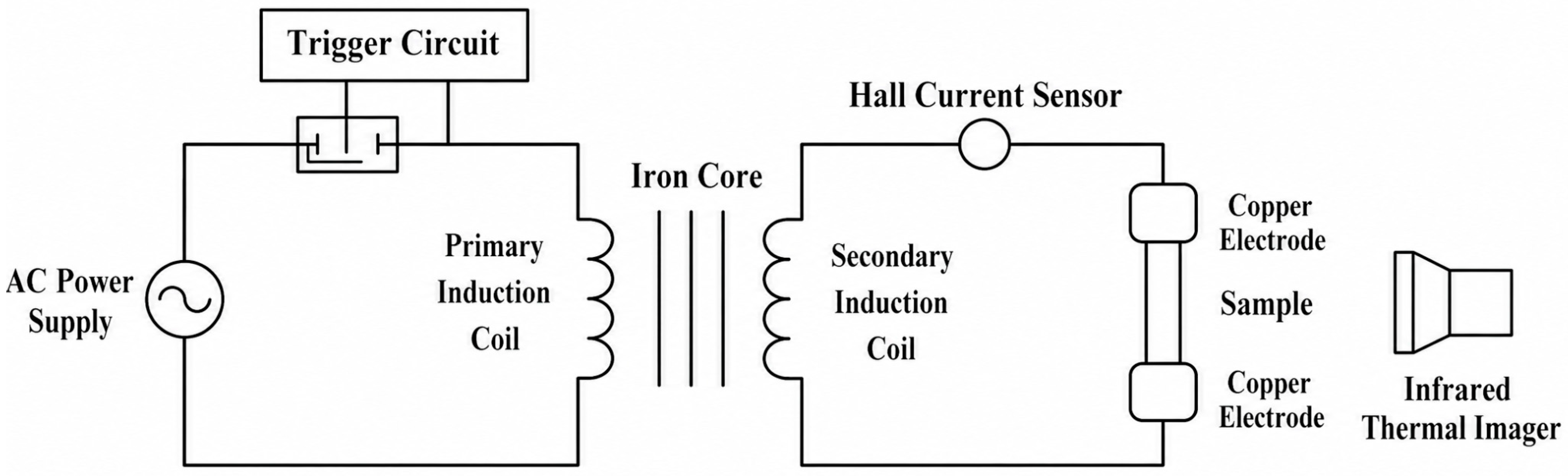
The raw material used in the experiment was 6082-T6 aluminum alloy rolled plates. The materials were divided into three groups: the first group received no treatment (WT); the second group underwent solution treatment followed by hot compression, water quenching, and artificial aging (IHC); the third group underwent electromagnetic shocking treatment (EST) based on the IHC condition. The optimal parameters for the IHC samples were determined through orthogonal experiments, culminating in a solution treatment at 535 °C for 0.5 h, deformation of 50% at a strain rate of 0.1 s−1, followed by artificial aging at 180 °C for 7 h. The optimal parameters for EST were determined by conducting further orthogonal experiments on the optimal IHC samples. Alternating current (AC) sinusoidal waves were used. The pulse frequency was 50 Hz, the treatment time was 0.04 s, and the peak current density was 70 A/mm2. The temperature rise on the sample surface measured by a thermal imager during the test was 32 °C. The alloy composition is shown in Table 1, the specimen sampling scheme is shown in Figure 1, and the schematic diagram of the electromagnetic shocking treatment is shown in Figure 2.

2.2. Tensile Tests and Charpy Impact Tests

Tensile tests were conducted on a universal testing machine (Shenzhen SUNS Technology Stock Co., Ltd., Shenzhen, China. Three tests were performed for each group of samples to obtain an average value. The Charpy impact specimens were cut into standard 5 × 10 × 55 mm unnotched impact specimens using an electrical discharge wire cutting machine, referring to the ASTM E23 standard [22]. Each set of experiments was repeated three times. The impact load–displacement curves were acquired through a data logger on a PTMS4660 pendulum impact testing machine (Shenzhen SUNS Technology Stock Co., Ltd., Shenzhen, China).

2.3. Microstructural Characterization

The EBSD testing in this text utilized a magnification of 200x. The sample surfaces were prepared using a combination of mechanical polishing and electropolishing. The electrolyte composition used for polishing was 7% HClO4 + 93% C2H5OH, and data processing was performed using Oxford Aztec Crystal software (4.0). TEM specimens were mechanically thinned to approximately 50 μm, and a 3 mm diameter disc was punched out. Ion thinning was then conducted using a 30% HNO3 methanol solution at −30 °C and 20 V. Observations were made using an FEI Tecnai G2 F30 S-TWIN transmission electron microscope (FEI Company, Hillsboro, OR, USA).

3. Results

3.1. Tensile Properties

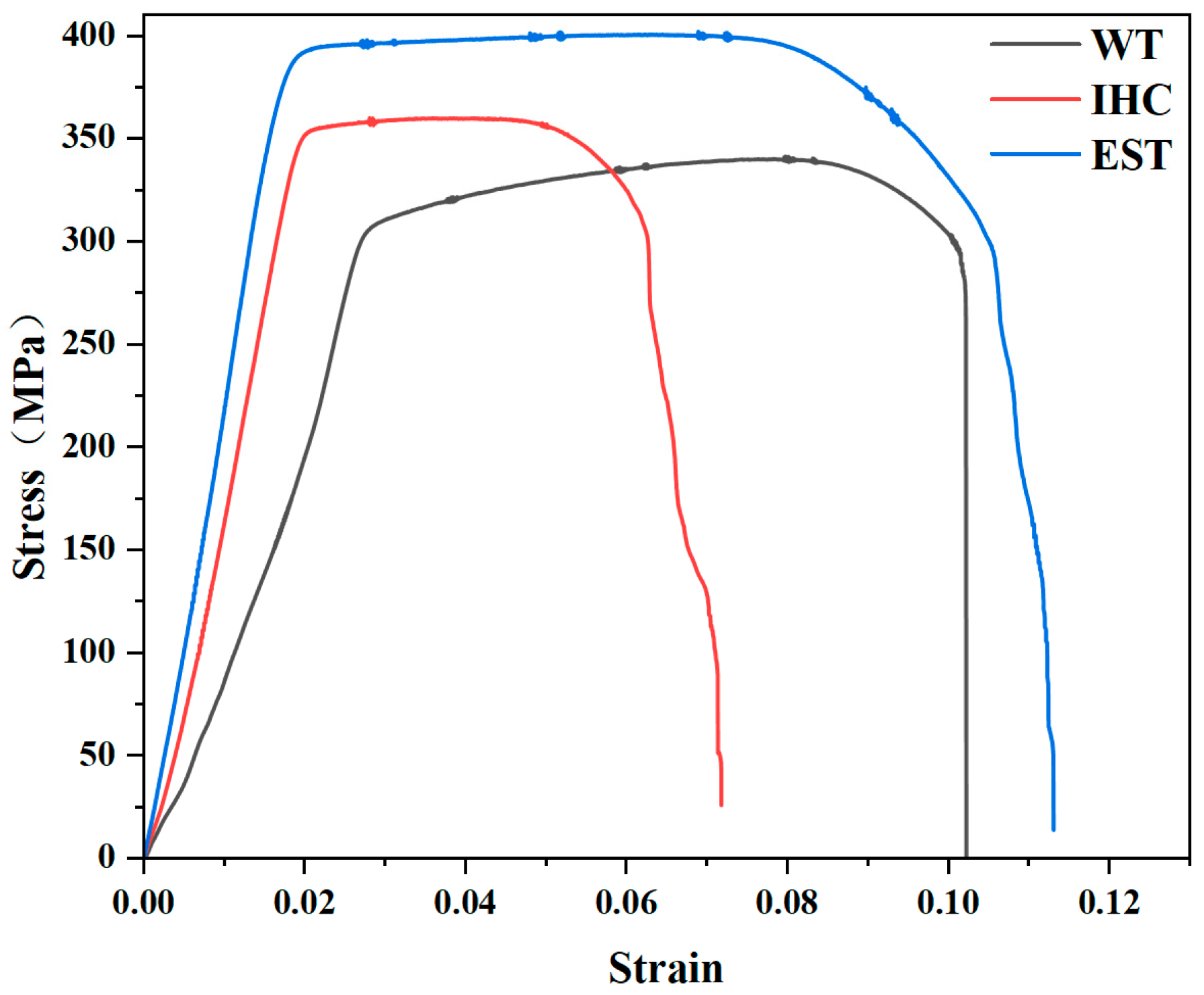
Figure 3 illustrates the engineering stress–strain curves for WT, IHC, and EST samples. The results indicate that compared to the WT sample, which has a tensile strength of 328 MPa, a yield strength of 306 MPa, and an elongation of 9.2%, the IHC sample shows an improvement in tensile strength (350 MPa) and yield strength (342 MPa), while its elongation drops to 6.6%. Compared to the IHC sample, the tensile strength of the EST sample further increases to 383 MPa, the yield strength increases to 376 MPa, and the elongation significantly rebounds to 9.4%, fundamentally reaching the same level as the initial WT state.

3.2. Impact Energy

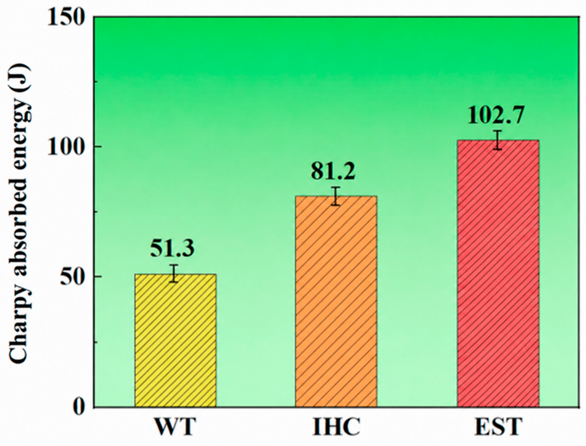
The impact energies of the WT, IHC, and EST samples are shown in Figure 4. Compared to the WT sample’s impact energy of 51.3 J, the impact energies of the IHC and EST samples increased to 81.2 J and 102.7 J, representing improvements of approximately 58.3% and 100.2%, respectively. Compared to the IHC sample, the EST sample’s impact energy increased by about 26.5%.
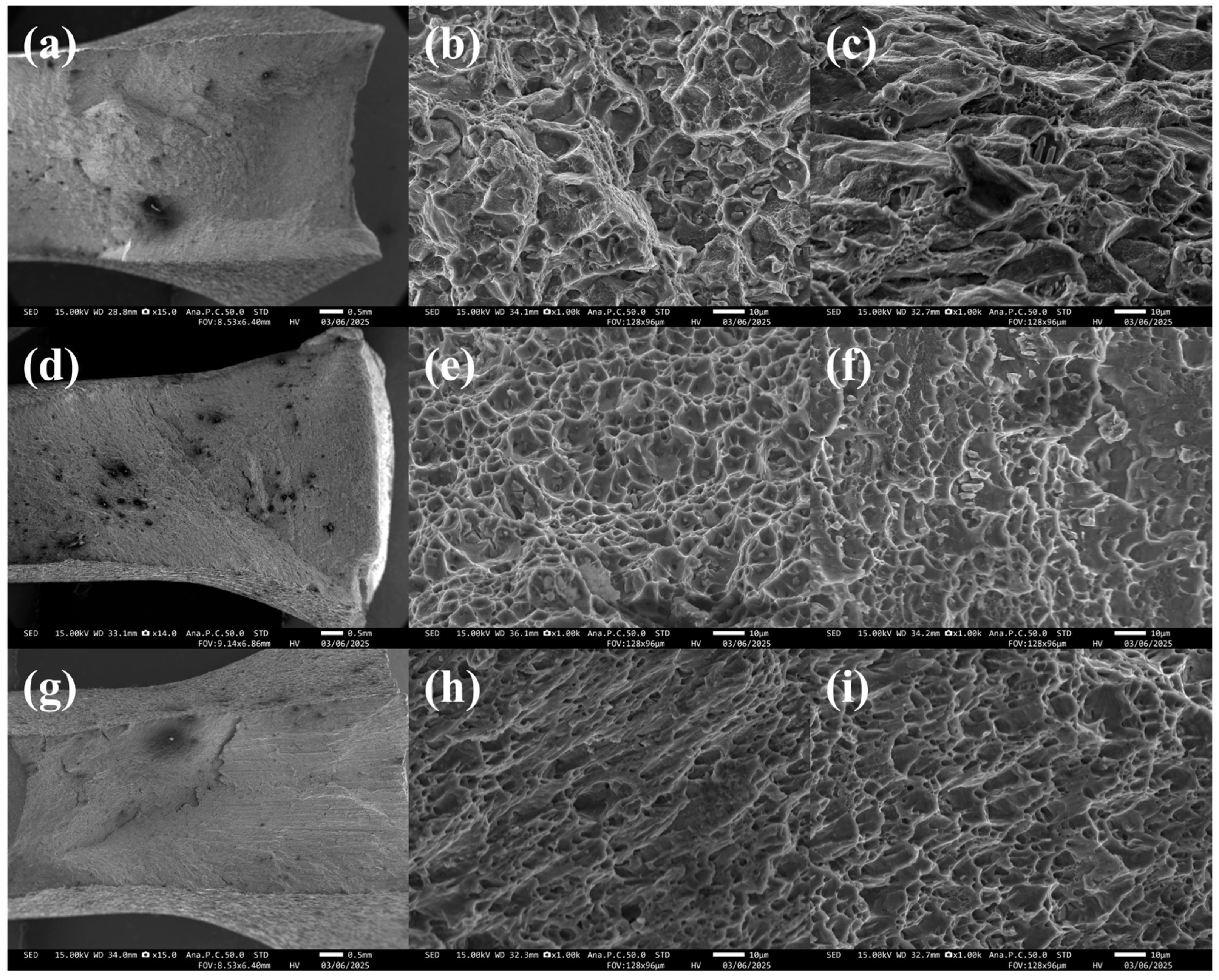
Figure 5a,d,g show the macroscopic impact fractures of the WT, IHC, and EST samples, respectively. Both the fibrous region and the shear lip region can be observed in all three groups. Macroscopically, the fracture surface of the WT sample is relatively flat, exhibiting lower roughness. In contrast, the undulation of the macroscopic fracture surface begins to increase in the IHC sample, as seen in Figure 5d. However, the most significant difference appears in the EST sample (Figure 5g), where the fracture surface is much rougher, and macroscopic shear steps and tear ridges can be observed. This change in macroscopic morphology indicates that, after electromagnetic shocking treatment, the crack is forced to deflect during propagation, forming a more tortuous path, thereby significantly increasing the energy consumption during the fracture process.
Analyzing the microscopic morphologies in Figure 5b,c,e,f,h,i, the fibrous and shear lip regions of the three groups are clearly discernible. For the WT sample, which has the lowest impact energy (51.3 J), its microscopic fracture (Figure 5b,c) primarily consists of shallow, flat dimples accompanied by localized cleavage features, indicating limited plastic deformation capacity before fracture. As shown in Figure 5e,f, when the hot compression process is introduced, although some cleavage planes appear in the shear lip region, the fracture mechanism in the fibrous region of the IHC sample is still dominated by micro-void coalescence, with increases in both the depth and size of the dimples. This is consistent with its impact energy increasing to 81.2 J.
In both the fibrous and shear lip regions of the EST sample (Figure 5h,i), a large number of deep, densely distributed dimples and thick tear ridges can be observed. This microstructural feature signifies that the material underwent severe plastic flow and void growth during fracture. This “deep dimple + large tear” characteristic intrinsically reflects the material’s excellent resistance to crack propagation, explaining why the EST sample’s impact energy sharply increased to 102.7 J.
In summary, by comparing the fracture characteristics across the three groups, it is evident that from the WT sample to the IHC sample, and finally to the EST sample, the plastic deformation features on the fracture surface (such as dimple depth and shear lip proportion) show a progressively strengthening trend (i.e., WT < IHC < EST). This evolutionary gradient of micro-morphology is fundamentally consistent with the increasing trend in absorbed impact energy (51.3 J < 81.2 J < 102.7 J).

3.3. Microstructure

3.3.1. Grain Morphology

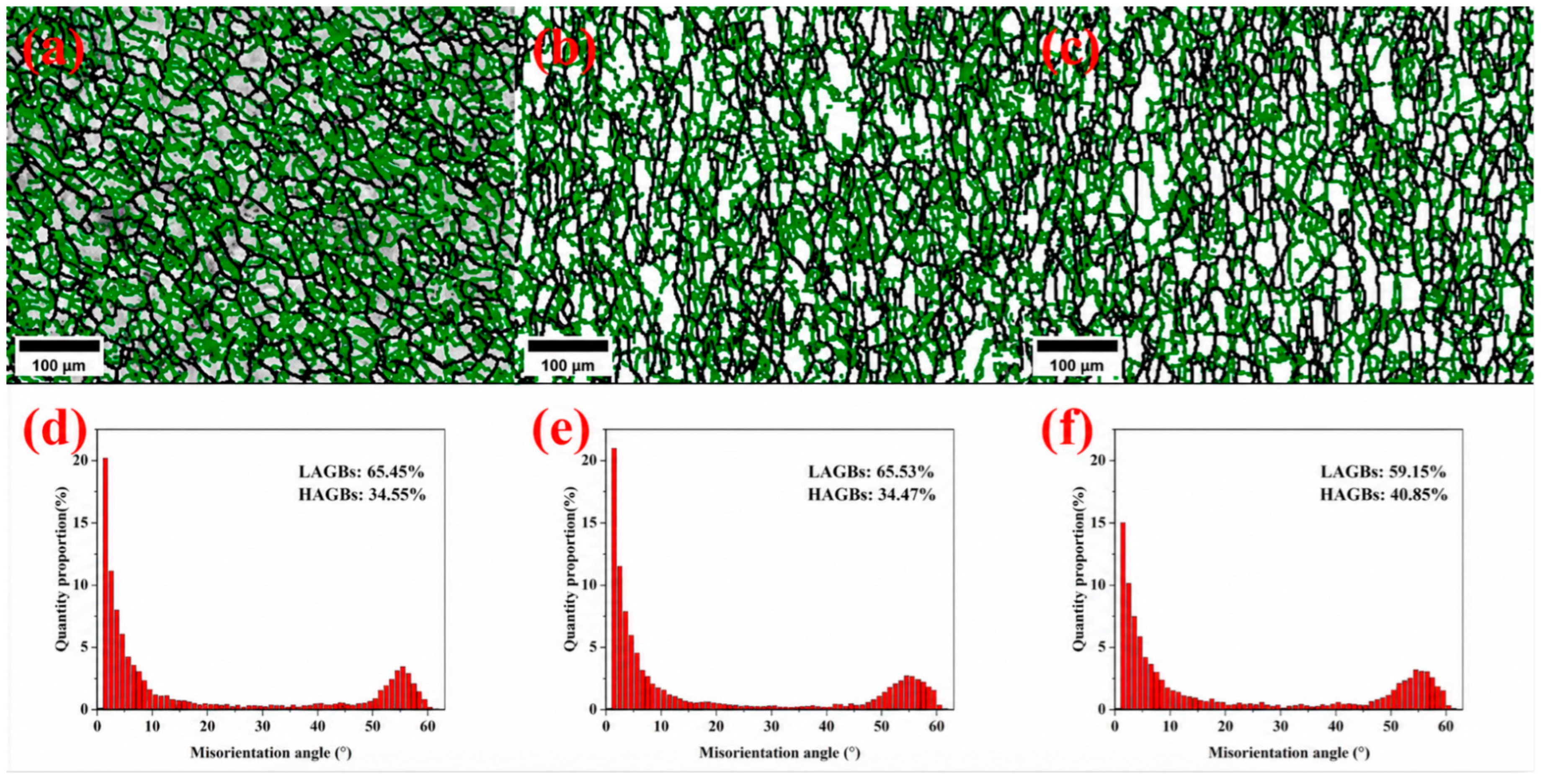
In Figure 6a–c, the green and black lines represent low-angle grain boundaries (LAGBs, misorientation < 15°) and high-angle grain boundaries (HAGBs, misorientation > 15°), respectively. The corresponding misorientation angle histograms are shown in Figure 6d,f. Comparing the WT and IHC samples, their grain boundary distribution characteristics are very similar, with HAGB proportions remaining essentially unchanged at 34.6% and 34.5%, respectively. For the EST sample, the HAGB proportion significantly increased to 40.9%.
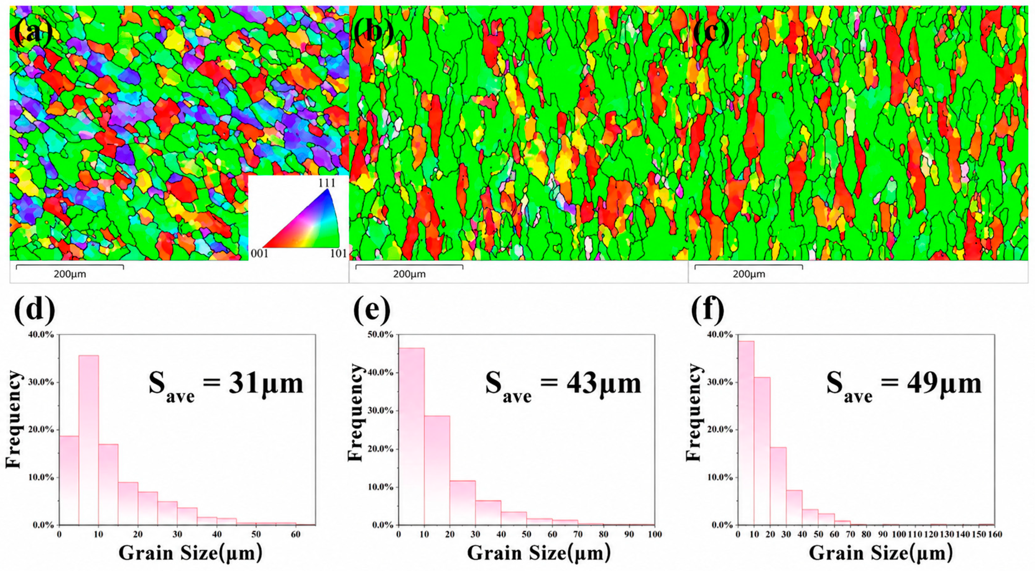
As depicted in Figure 7d–f, the average grain sizes of the WT, IHC, and EST samples are 31 μm, 43 μm, and 49 μm, respectively. As shown in Figure 7a, the grain orientation of the WT sample is random, with no obvious texture formed. In the IHC sample (Figure 7b) and EST sample (Figure 7c), the vast majority of areas in the field of view exhibit a distinct ⟨101⟩ orientation. This indicates that a strong ⟨101⟩ preferred orientation, or fiber texture, was formed inside the material following hot compression deformation. Furthermore, after electromagnetic shocking treatment, this ⟨101⟩ preferred orientation was preserved in the EST sample.
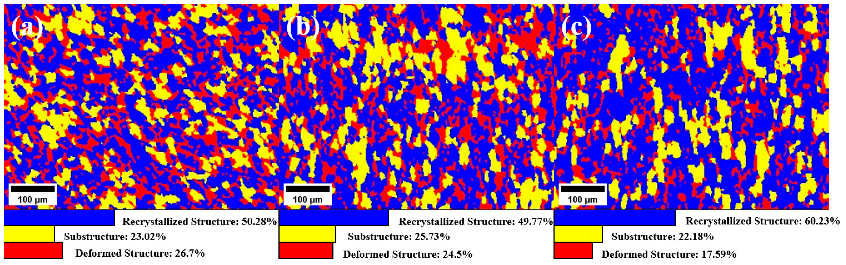
In Figure 8a–c, the blue, yellow, and red regions represent recrystallized structure, substructure, and deformed structure, respectively. Regarding the proportion of deformed structure: WT (26.7%) > IHC (24.5%) > EST (17.6%). This demonstrates that with the sequential introduction of hot compression and EST processing, the deformation stored energy inside the material is gradually consumed. Meanwhile, the proportion of recrystallized structure in the EST sample (60.2%) is significantly higher than that in the WT sample (50.3%) and the IHC sample (49.8%). This indicates that EST effectively promoted the occurrence of static recrystallization, transforming deformed structures into recrystallized grains.

3.3.2. Precipitate Distribution

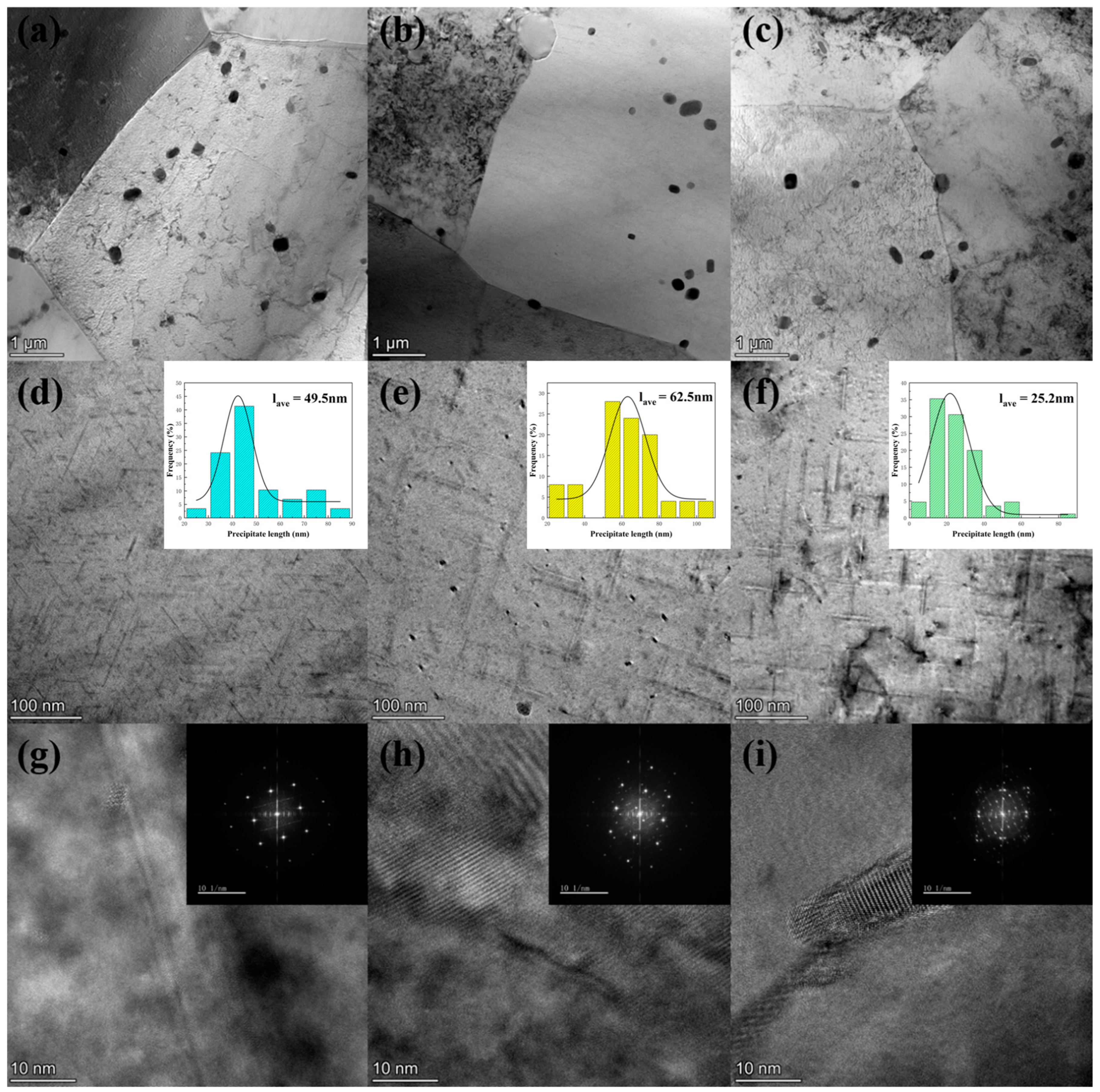
As shown in Figure 9a–c, the grain boundary contours of the three groups are relatively clear, and some micrometer-scale coarse iron-rich phases or undissolved second-phase particles are distributed both within the grains and at the boundaries. At this scale, the differences among the three are not pronounced.
As shown in Figure 9d–f, the lengths of the precipitates for the three groups were statistically analyzed using Image-Pro Plus. The precipitates in all three cases are acicular. The average length of the precipitates in the intragranular matrix of the WT sample is 25.2 nm. In the IHC sample, the precipitates coarsened significantly, with the average length increasing to 62.5 nm. Conversely, the average length of the precipitates in the EST sample decreased to 49.5 nm, a reduction of 20.8% compared to the IHC sample. Based on the areal density formula NA = N/A (where N is the number of precipitates in the field of view, and A is the statistical field area), the areal densities of precipitates in the WT, IHC, and EST samples were calculated to be 3.6 × 10¹⁴ m−2, 1.1 × 10¹⁴ m−2, and 1.2 × 10¹⁴ m−2, respectively.

3.3.3. Dislocation Distribution

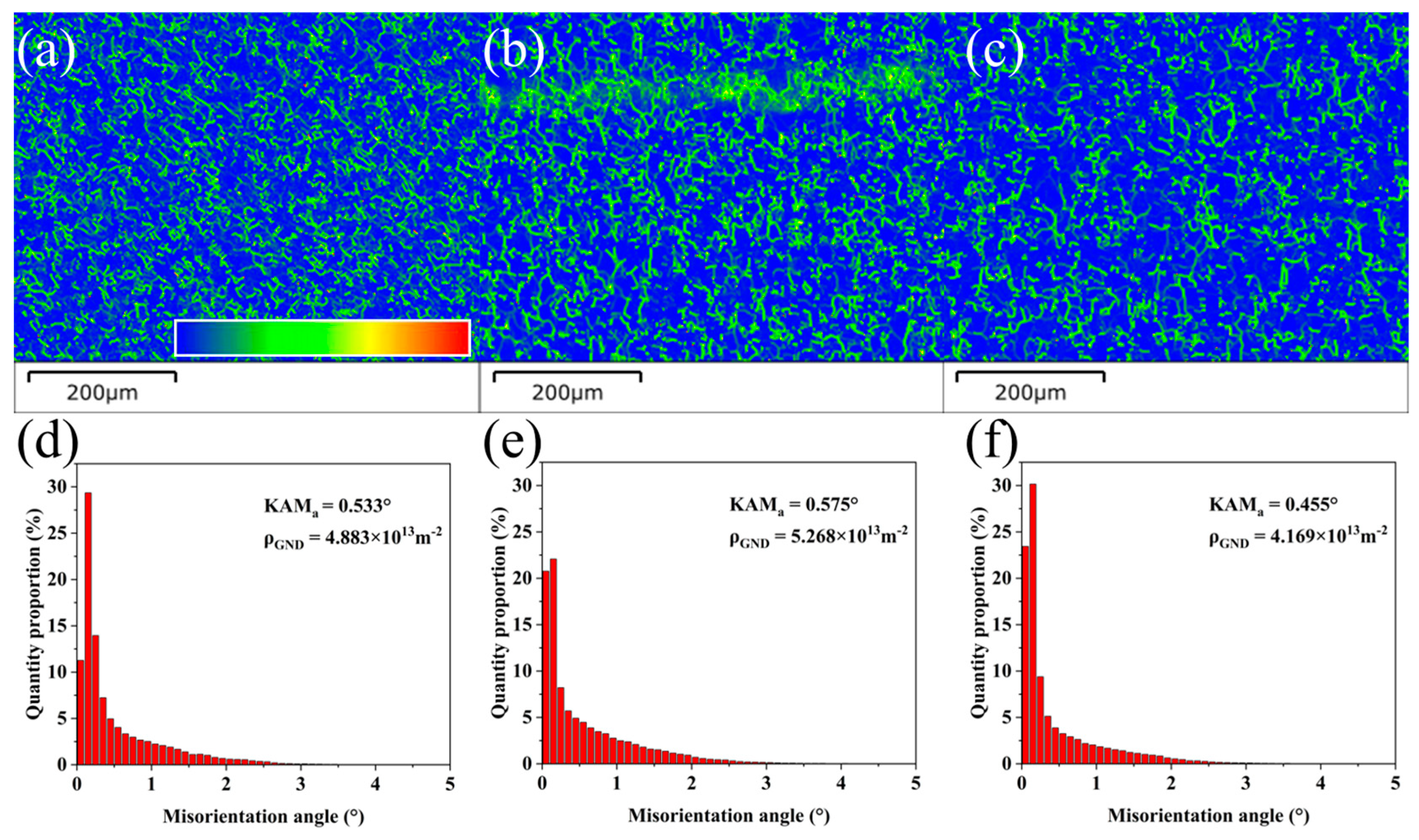
The geometrically necessary dislocation (GND) density can be calculated from the kernel average misorientation (KAM), which is statistically derived from EBSD as previously discussed. As shown in Figure 10d–f, the KAM values for the WT, IHC, and EST samples are 0.533, 0.575, and 0.455, respectively. The GND density is generally calculated by the following equation [23,24]:
ρ G N D = k θ b μ
where the value of the geometric constant k depends on the type of dislocation [24]; in this paper, k = 3 is selected. b is the magnitude of the Burgers vector, typically taken as 0.286 nm, and μ is the distance between KAM angles, representing the scanning step size.
The calculated GND densities of the WT, IHC, and EST samples are 4.883 × 10¹³ m−2, 5.268 × 10¹³ m−2, and 4.169 × 10¹³ m−2, respectively. Compared with the WT sample, the GND density of the IHC sample increases by approximately 7.9%, indicating that hot compression introduces additional lattice curvature and deformation-induced dislocation structures into the alloy. This increase can be attributed to the accumulation of dislocations during plastic deformation. Under hot compression, dislocations are continuously generated to accommodate local strain gradients and coordinate the plastic incompatibility among neighboring grains [25]. Although dynamic recovery may occur in aluminum alloys because of their high stacking-fault energy, which facilitates dislocation climb and cross-slip at elevated temperatures [26], the short deformation process and subsequent aging treatment still allow part of the deformation-induced dislocation structure to be retained.
After EST, the GND density decreases significantly to 4.169 × 10¹³ m−2, which is approximately 20.9% lower than that of the IHC sample. This result indicates that EST promotes dislocation annihilation and rearrangement. The high-energy pulsed electromagnetic field can enhance atomic diffusion and local interface migration, thereby facilitating dislocation recovery, reducing lattice distortion, and lowering the stored deformation energy [27,28]. This is consistent with the reduced fraction of deformed structures and the increased fraction of recrystallized structures observed in the EST sample. Therefore, the dislocation evolution follows the trend IHC > WT > EST.

4. Discussion

Although the IHC sample exhibits higher tensile strength and yield strength than the WT sample, this improvement cannot be simply attributed to grain refinement or enhanced precipitation strengthening. Compared with the WT sample, the IHC sample has a larger average grain size and coarser precipitates with a lower areal density, which are not favorable for conventional Hall–Petch strengthening or high-density fine-precipitate strengthening. Therefore, the strength enhancement of the IHC sample should be attributed to the combined effects of several factors.
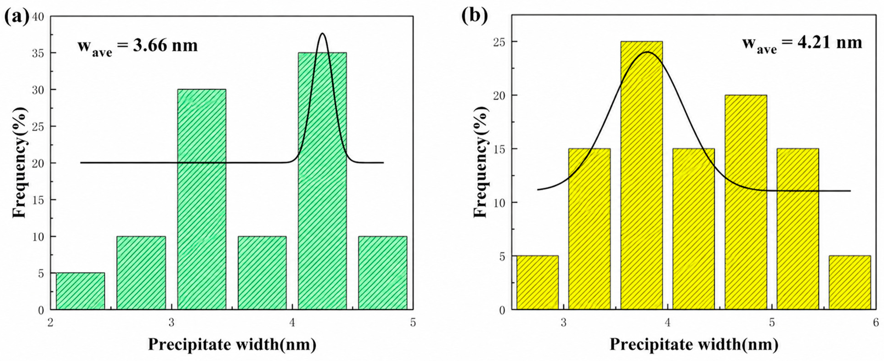
First, the GND density increases from 4.883 × 10¹³ m−2 in the WT sample to 5.268 × 10¹³ m−2 in the IHC sample, indicating that part of the deformation-induced dislocation structure is retained after hot compression and aging. These retained dislocations, together with possible statistically stored dislocations and substructures, can hinder dislocation glide and contribute to strength enhancement. Second, the pronounced ⟨101⟩ preferred orientation formed during hot compression may change the effective Schmid factor under tensile loading, making slip activation more difficult [29]. Third, as shown in Figure 9 and Figure 11, the increased precipitate width and reduced aspect ratio are considered to possibly alter the dislocation–precipitate interaction and thereby contribute to the enhanced strength of the EST sample [30,31].
Compared to the IHC sample, the EST sample possesses an even larger grain size, a lower GND density, and shorter precipitates; however, its tensile strength increased by 9.4%, yield strength by 9.9%, and impact energy by 26.5%. Neither the microstructural changes in the IHC sample nor those in the EST sample alone seem to adequately explain the macroscopic enhancement in tensile strength and impact energy. Therefore, there are likely other critical factors influencing the alloy’s properties.

4.1. Striped Grain Boundaries and Interface Wetting

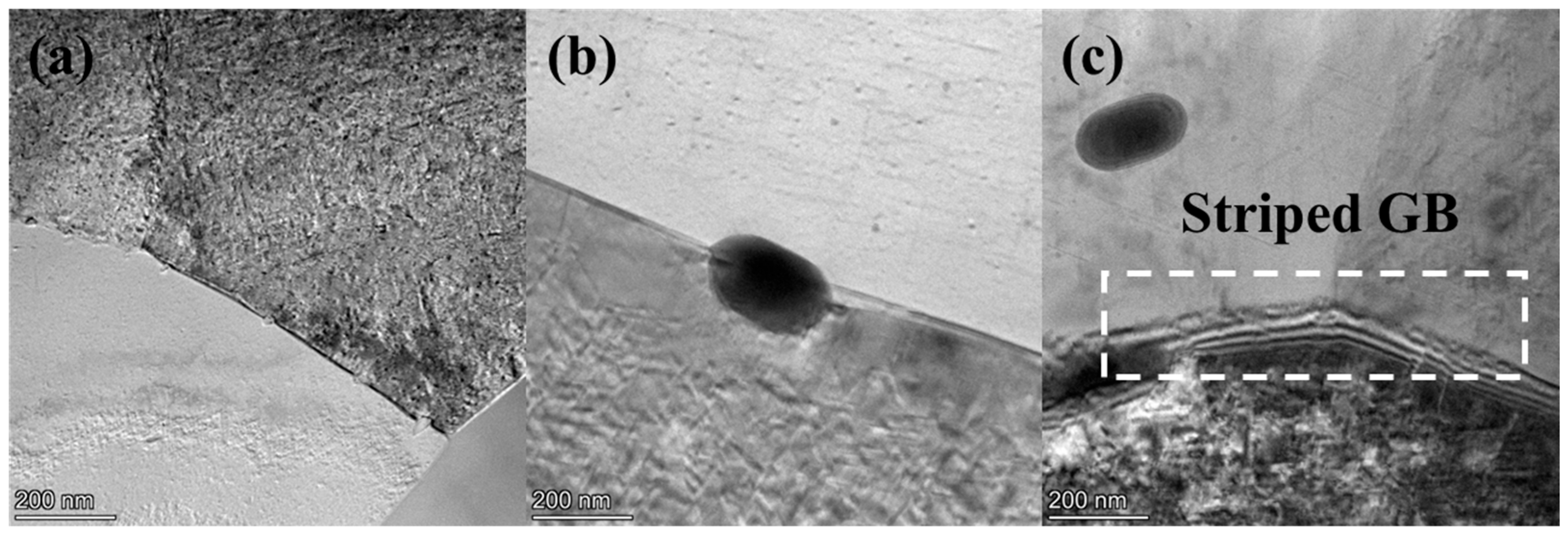
Figure 12 displays the grain boundaries of the WT, IHC, and EST samples under a certain field of view. Relatively clear and flat grain boundaries can be observed in the WT sample. In contrast, faintly striped grain boundaries begin to appear in the IHC sample, and these striped grain boundary features become particularly distinct in the EST sample. According to previous research [32,33], the formation of these striped grain boundaries can be primarily attributed to the electromagnetic shocking treatment. According to traditional theory, the migration and diffusion of atoms rely mainly on thermal fluctuations. Compared to the IHC sample, the grain coarsening, phase dissolution, and dislocation annihilation observed in the EST sample require sufficient temperature and time to complete [34]. However, the surface temperature rise during EST was only 32 °C, and the action time was a mere 0.04 s, yet the sample’s microstructure still evolved. This can partially be attributed to the localized Joule heating and electron wind force induced by the EST. In an ideal, perfect crystal lattice, electrons move freely without generating much heat. However, severe lattice distortion occurs at defects (such as grain boundaries, phase boundaries, and dislocations). When the high-speed electron flow passes through these defects, it scatters strongly with the atomic nuclei at these sites, transferring part of its momentum to the nuclei and generating a driving force on the atoms [35,36]. Concurrently, the electron stream loses a significant amount of kinetic energy, which converts into lattice thermal vibrations, generating heat. Because the microscopic resistivity at defects is much higher than that within the grains, the heat generation rate at these defects is substantially greater. Under their combined action, atoms oscillate at the nanoscale interfaces, causing the interface to exhibit a “wave-like” striped pattern. It can be inferred that pre-melting or wetting of the interfaces occurred under the influence of EST [32].
However, the localized Joule heating and electron wind force effects alone do not seem sufficient to fully explain the changes observed at the grain and phase boundaries in the experimental results. On the one hand, while localized Joule heating results in a higher heat generation rate at boundaries and dislocations compared to the grain interior, there is a lack of direct, quantitative evidence to confirm that the melting temperature was actually reached. On the other hand, due to the relatively low current density adopted for EST in this study, the effect of the electron wind force on the internal structure is not dominant [37,38]. In addition to localized Joule heating and electron-wind effects, the alternating current applied during EST creates a time-dependent electromagnetic environment. In the previous study [39], an assumed mass–spring–damping system was introduced as a phenomenological framework to describe the possible dynamic response of heterogeneous metallic interfaces under EST. Following this concept, an interfacial region may be schematically represented by a mass, stiffness, and damping system:
d 2 x ( t ) d t + 2 ξ ω n x ( t ) d t + ω n 2 x ( t ) = F ( t ) m
where ξ is the damping ratio, η is the viscosity coefficient of the viscoid, m is the mass of the system, ωn is the intrinsic frequency of the system, F(t) is the external input force and x(t) is the output displacement of the system.
Structurally heterogeneous regions at grain boundaries or phase boundaries may exhibit different transient responses to the time-dependent EST excitation because their local structural state, defect density, stiffness, and damping characteristics are different. Such spatially nonuniform responses may facilitate local atomic rearrangement and interface migration, resulting in heterogeneous interfacial reconstruction. It is hypothesized that local interfacial reconstruction may further lead to interface bridging under favorable conditions. This interface bridging is a key factor in explaining the improvement in the material’s impact toughness.
When atoms migrate and merge across grain boundaries, the grains develop a tendency to grow, which explains why the grain size of the EST sample is larger than that of the IHC and WT samples. Although stripes at the phase boundaries were not directly observed via TEM, since the precipitates in the EST sample dissolved compared to the IHC sample, it is reasonable to deduce that a certain degree of phase boundary wetting also occurred in the EST sample [32].

4.2. Interface Bridging Enhances Impact Toughness

Studies have shown that heat treatment and hot compression can also promote the generation of striped grain boundaries [33], suggesting that interface pre-melting and wetting might also occur in the IHC sample. It can be inferred that varying degrees of interface bridging transpired within both the IHC and EST samples. Due to the uneven distribution of stress, temperature, and electromagnetic fields, EST-induced interface bridging is typically non-linear. There are regions of strength and weakness across the interface. In strong zones, atoms bond together to form high-strength “bridge piers”. Conversely, in weak zones, effective bridging is absent, and microscopic voids may even remain. When a crack approaches these alternating strong and weak regions at the interface, the crack tip is easily attracted by the continuously distributed weak zones, deflecting its original propagation path and making the route more tortuous. Once the crack enters the bridged regions, it encounters the strong zones while propagating along the interface. For the crack to pass through these strong zones, it must tear apart the interface bridging, meaning the crack must absorb more energy to continue its propagation. Under the combined effect of both phenomena, the impact energy of the sample is enhanced. This elucidates why the EST sample’s impact energy is significantly higher than that of the WT and IHC samples. For the IHC sample under thermo-mechanical coupling, the interface condition is highly uncontrollable. If the degree of local grain boundary bridging is inadequate and more weak zones exist between grain boundaries, the overall capability of the strong zones to resist crack propagation is diminished after cracks are drawn into the bridged areas. This is a crucial reason why the IHC sample, which also experienced interface bridging, exhibited lower impact energy than the EST sample.
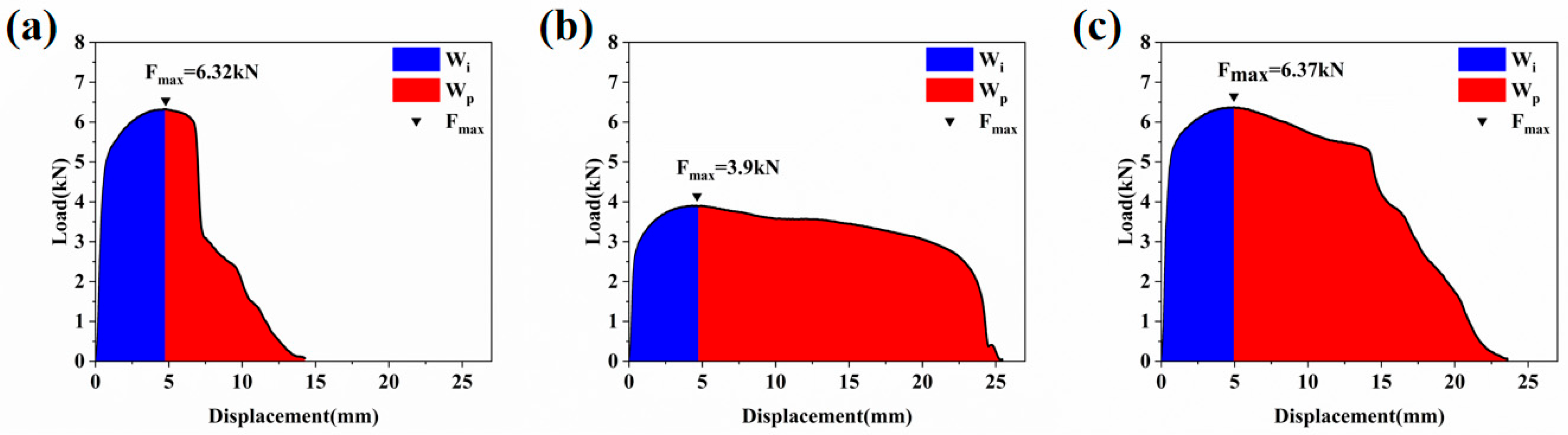
Figure 13 presents the impact load–displacement curves for the WT, IHC, and EST samples. The results indicate that the crack initiation energy is almost identical for the WT and EST samples, but the crack initiation energy of the IHC sample is significantly lower. One possible explanation for the lower crack-initiation energy of the IHC sample is that its interfaces may contain a larger number of locally weak or incompletely bridged regions. If present, these regions could act as preferential sites for local stress concentration and facilitate crack initiation, thereby reducing the energy required for crack initiation. In contrast, the EST sample, which also underwent interface bridging, may feature fewer weak zones due to the excellent state of interface bridging, hindering the formation of microcracks and naturally yielding higher crack initiation energy. Regarding crack propagation energy, the values of both the IHC and EST samples are substantially higher than that of the WT sample because the cracks absorbed more energy to penetrate the bridged regions while propagating along the grain boundaries. The experimental results validate the prior analysis, confirming that the interface bridging state in the IHC sample is poorer, whereas it is superior in the EST sample.

5. Conclusions

(1)
Compared to the WT sample, the yield strength and tensile strength of the IHC sample increased by approximately 11.8% and 6.7% respectively, while its elongation decreased by about 28.3%. For the EST sample, compared to the WT sample, its yield strength and tensile strength increased by approximately 22.9% and 16.8% respectively, and its elongation increased by about 2.2%. The results indicate that EST can substantially improve the strength of the alloy while maintaining its plasticity.
(2)
Compared to the WT sample, the impact energy of the IHC sample increased by approximately 58.3%, and that of the EST sample increased by roughly 100.2%. Experimental outcomes demonstrate that hot compression and aging treatments can effectively raise the sample’s impact energy, and EST can further elevate it based on those preliminary enhancements.
(3)
Compared to the WT sample, the grain size and precipitate length of the IHC sample increased by 38.7% and 148.0%, respectively. Following EST, compared to the WT sample, the sample’s overall grain size increased by 58.1%, while compared to the IHC sample, its precipitate length decreased by 20.8%, and the dislocation density also declined. The changes in grain size and precipitate dimensions are associated with the dissolution of grain boundary/phase boundary regions induced by interface wetting.
(4)
The striped grain boundaries observed in both the IHC and EST samples are considered to be associated with the occurrence of interface wetting, although the local interfacial temperature could not be quantitatively measured to verify whether it reached the melting point, from which it can be further inferred that interface bridging may have occurred. Interface bridging can attract cracks into the bridged zones, deflecting the crack propagation path. Furthermore, it forces the cracks to tear through the interface bridging, effectively enhancing the crack propagation energy of the alloy.

Author Contributions

Conceptualization, Q.S.; Methodology, J.Z.; Validation, Q.X.; Investigation, Q.S. and J.Z.; Resources, Q.X.; Data curation, Q.X. and J.Z.; Writing—original draft preparation, Q.S. and J.Z. All authors have read and agreed to the published version of the manuscript.

Funding

This work was financially supported by the National Natural Science Foundation of China (Grant No. 52273319), the 111 Project (Grant No. B17034) and Innovative Research Team Development Program of Ministry of Education of China (Grant No. IRT_17R83).

Data Availability Statement

The original contributions presented in the study are included in the article. Further inquiries can be directed to the corresponding author.

Conflicts of Interest

The authors declare no conflicts of interest. The funders had no role in the design of the study; in the collection, analyses, or interpretation of data; in the writing of the manuscript; or in the decision to publish the results.

References

  1. Gu, Y.-F.; Liu, W.-P.; Guo, H.-S.; Zhang, C.-X.; Luo, J.-T. Preparation of High Performance 5083 Aluminum Alloy by Alternate Ring-Groove Pressing and Torsion. Trans. Nonferrous Met. Soc. China 2023, 33, 383–395. [Google Scholar] [CrossRef] [Scilit]
  2. Suryawanshi, J.; Prashanth, K.G.; Scudino, S.; Eckert, J.; Prakash, O.; Ramamurty, U. Simultaneous Enhancements of Strength and Toughness in an Al-12Si Alloy Synthesized Using Selective Laser Melting. Acta Mater. 2016, 115, 285–294. [Google Scholar] [CrossRef] [Scilit]
  3. Li, S.-H.; Han, W.-Z.; Li, J.; Ma, E.; Shan, Z.-W. Small-Volume Aluminum Alloys with Native Oxide Shell Deliver Unprecedented Strength and Toughness. Acta Mater. 2017, 126, 202–209. [Google Scholar] [CrossRef] [Scilit]
  4. Ghorbani, H.; Jamaati, R. Breakthrough the Strength-Ductility Trade-off in AA7075 Alloy by Gradient Microstructure. Arch. Civ. Mech. Eng. 2023, 23, 245. [Google Scholar] [CrossRef] [Scilit]
  5. Wu, G.; Liu, C.; Sun, L.; Wang, Q.; Sun, B.; Han, B.; Kai, J.-J.; Luan, J.; Liu, C.T.; Cao, K.; et al. Hierarchical Nanostructured Aluminum Alloy with Ultrahigh Strength and Large Plasticity. Nat. Commun. 2019, 10, 5099. [Google Scholar] [CrossRef] [Scilit] [PubMed]
  6. Du, J.; Zhang, Z.; Liu, Y.; Shao, Q.; Zhang, A.; Xiong, S.; Liu, F. Strength-Ductility Trade-off Modulated by Thermo-Kinetic Synergy of Heat-Treatable Aluminum Alloys. J. Mater. Res. Technol. 2023, 24, 7876–7895. [Google Scholar] [CrossRef] [Scilit]
  7. Amne Elahi, M.; Shabestari, S.G. Effect of Various Melt and Heat Treatment Conditions on Impact Toughness of A356 Aluminum Alloy. Trans. Nonferrous Met. Soc. China 2016, 26, 956–965. [Google Scholar] [CrossRef] [Scilit]
  8. Meyer, L.W.; Schönherr, R.; Hockauf, M. Increasing Strength, Ductility and Impact Toughness of Ultrafine-Grained 6063 Aluminium Alloy by Combining ECAP and a High-Temperature Short-Time Aging. J. Phys. Conf. Ser. 2010, 240, 012123. [Google Scholar] [CrossRef] [Scilit]
  9. Ma, A.; Suzuki, K.; Nishida, Y.; Saito, N.; Shigematsu, I.; Takagi, M.; Iwata, H.; Watazu, A.; Imura, T. Impact Toughness of an Ultrafine-Grained Al–11mass%Si Alloy Processed by Rotary-Die Equal-Channel Angular Pressing. Acta Mater. 2005, 53, 211–220. [Google Scholar] [CrossRef] [Scilit]
  10. Subramaniam, B.; Natarajan, B.; Kaliyaperumal, B.; Chelladurai, S.J.S. Investigation on Mechanical Properties of Aluminium 7075—Boron Carbide—Coconut Shell Fly Ash Reinforced Hybrid Metal Matrix Composites. China Foundry 2018, 15, 449–456. [Google Scholar] [CrossRef] [Scilit]
  11. Hao, Y.; Ye, Z.; Ye, M.; Dong, H.; Wang, L.; Du, Y. Construction and Growth of Black PEO Coatings on Aluminum Alloys for Enhanced Wear and Impact Resistance. Ceram. Int. 2023, 49, 30782–30793. [Google Scholar] [CrossRef] [Scilit]
  12. Cepeda-Jiménez, C.; García-Infanta, J.; Pozuelo, M.; Ruano, O.; Carreño, F. Impact Toughness Improvement of High-Strength Aluminium Alloy by Intrinsic and Extrinsic Fracture Mechanisms via Hot Roll Bonding. Scr. Mater. 2009, 61, 407–410. [Google Scholar] [CrossRef] [Scilit]
  13. Xu, Q.; Tang, G.Y.; Jiang, Y.B. Thermal and Electromigration Effects of Electropulsing on Dynamic Recrystallization in Mg–3Al–1Zn Alloy. Mater. Sci. Eng. A 2011, 528, 4431–4436. [Google Scholar] [CrossRef] [Scilit]
  14. Shan, Z.; Bai, J.; Fan, J.; Wu, H.; Zhang, H.; Zhang, Q.; Wu, Y.; Li, W.; Dong, H.; Xu, B. Exceptional Mechanical Properties of AZ31 Alloy Wire by Combination of Cold Drawing and EPT. J. Mater. Sci. Technol. 2020, 51, 111–118. [Google Scholar] [CrossRef] [Scilit]
  15. Rahman, H.; Todaro, S.; Warner, L.; Waryoba, D.; Haque, A. Elimination of Low-Angle Grain Boundary Networks in FeCrAl Alloys with the Electron Wind Force at a Low Temperature. Metals 2024, 14, 331. [Google Scholar] [CrossRef] [Scilit]
  16. Cai, Q.; Zhou, M.; Bagherpour, E.; Hosseini, S.; Mendis, C.; Chang, I.; Assadi, H. New Insight Into Crack-Healing Mechanism via Electropulsing Treatment. Metall. Mater. Trans. A 2023, 54, 2960–2974. [Google Scholar] [CrossRef] [Scilit]
  17. Li, N.; Zhang, L.; Zhang, R.; Yin, P.; Wu, H.; Song, K.; Xing, H. The Role of Electric Current-Associated Free Energy and Forced Convection on Grain Refinement in Pure Aluminum under Electropulsing. Materials 2019, 12, 3846. [Google Scholar] [CrossRef] [Scilit] [PubMed]
  18. Wang, Y.; Zhao, Y.; Xu, X.; Pan, D.; Jiang, W.; Chong, X. Simultaneously Enhanced Strength and Ductility of Al–Mg–Si Alloys during Aging Process Induced by Electro-Pulsing Treatment. Materials 2019, 12, 1383. [Google Scholar] [CrossRef] [Scilit] [PubMed]
  19. Hong, S.-T.; Jeong, Y.-H.; Chowdhury, M.N.; Chun, D.-M.; Kim, M.-J.; Han, H.N. Feasibility of Electrically Assisted Progressive Forging of Aluminum 6061-T6 Alloy. CIRP Ann. 2015, 64, 277–280. [Google Scholar] [CrossRef] [Scilit]
  20. Pan, D.; Wang, Y.; Guo, Q.; Zhang, D.; Xu, X.; Zhao, Y. Grain Refinement of Al–Mg–Si Alloy without Any Mechanical Deformation and Matrix Phase Transformation via Cyclic Electro-Pulsing Treatment. Mater. Sci. Eng. A 2021, 807, 140916. [Google Scholar] [CrossRef] [Scilit]
  21. Hameed, S.; Rojas, H.A.G.; Benavides, J.I.P.; Alberro, A.N.; Egea, A.J.S. Influence of the Regime of Electropulsing-Assisted Machining on the Plastic Deformation of the Layer Being Cut. Materials 2018, 11, 886. [Google Scholar] [CrossRef] [Scilit] [PubMed]
  22. ASTM E23-25; Standard Test Methods for Notched Bar Impact Testing of Metallic Materials. ASTM International: West Conshohocken, PA, USA, 2025.
  23. Xu, X.; Zhao, Y.; Wang, X.; Zhang, Y.; Ning, Y. Effect of Rapid Solid-Solution Induced by Electropulsing on the Microstructure and Mechanical Properties in 7075 Al Alloy. Mater. Sci. Eng. A 2016, 654, 278–281. [Google Scholar] [CrossRef] [Scilit]
  24. Calcagnotto, M.; Ponge, D.; Demir, E.; Raabe, D. Orientation Gradients and Geometrically Necessary Dislocations in Ultrafine Grained Dual-Phase Steels Studied by 2D and 3D EBSD. Mater. Sci. Eng. A 2010, 527, 2738–2746. [Google Scholar] [CrossRef] [Scilit]
  25. Chakravarty, P.; Pál, G.; Sidor, J.J. The Dependency of Work Hardening on Dislocation Statistics in Cold Rolled 1050 Aluminum Alloy. Mater. Charact. 2022, 191, 112166. [Google Scholar] [CrossRef] [Scilit]
  26. Zheng, J.-H.; Pruncu, C.; Zhang, K.; Zheng, K.; Jiang, J. Quantifying Geometrically Necessary Dislocation Density during Hot Deformation in AA6082 Al Alloy. Mater. Sci. Eng. A 2021, 814, 141158. [Google Scholar] [CrossRef] [Scilit]
  27. Lin, H.-B. Dynamic Recrystallization Behavior of 6082 Aluminum Alloy during Hot Deformation. Adv. Mech. Eng. 2021, 13, 1–10. [Google Scholar] [CrossRef] [Scilit]
  28. Chen, K.; Zhan, L.; Xu, Y.; Liu, Y. Effect of Pulsed Current Density on Creep-Aging Behavior and Microstructure of AA7150 Aluminum Alloy. J. Mater. Res. Technol. 2020, 9, 15433–15441. [Google Scholar] [CrossRef] [Scilit]
  29. Liu, Q.; Fan, W.; Ren, Z.; Wang, T.; Huang, Q. Effect of Pulsed Current Treatment on Microstructure and Properties of 304 Stainless Steel Ultra-Thin Strip after Rolling. Chin. J. Mech. Eng. 2024, 37, 149. [Google Scholar] [CrossRef] [Scilit]
  30. Teichmann, K.; Marioara, C.D.; Andersen, S.J.; Marthinsen, K. TEM Study of Β′ Precipitate Interaction Mechanisms with Dislocations and Β′ Interfaces with the Aluminium Matrix in Al–Mg–Si Alloys. Mater. Charact. 2013, 75, 1–7. [Google Scholar] [CrossRef] [Scilit]
  31. Christiansen, E.; Marioara, C.D.; Holmedal, B.; Hopperstad, O.S.; Holmestad, R. Nano-Scale Characterisation of Sheared β Precipitates in a Deformed Al-Mg-Si Alloy. Sci. Rep. 2019, 9, 17446. [Google Scholar] [CrossRef] [Scilit] [PubMed]
  32. Sun, Q.; Liu, L.; Yu, S.; Wang, H.; Wang, H. Gradient Phase Transformation of Al–Zn–Mg–Cu Alloy Induced by Nonlinear Interface Wetting under Electromagnetic Shocking Treatment. J. Mater. Sci. 2023, 58, 16239–16255. [Google Scholar] [CrossRef] [Scilit]
  33. Sun, Q.; Xu, C.; Yu, S.; Hu, Z. Effect of Isothermal Multidirectional Compression on Microstructure and Mechanical Properties of Al–Zn–Mg–Cu–Zr Alloy with Minor Sc Addition. Mater. Chem. Phys. 2024, 313, 128769. [Google Scholar] [CrossRef] [Scilit]
  34. Porter, D.A.; Easterling, K.E. Phase Transformations in Metals and Alloys (Revised Reprint); CRC Press: Boca Raton, FL, USA, 2009. [Google Scholar]
  35. Zhu, J.; Lin, Y.; Liu, S.; Lin, X.; Wang, G. Electropulsing Aging Treatment of Cu–Ni–Si Sheet for Microforming. Adv. Eng. Mater. 2021, 23, 2100249. [Google Scholar] [CrossRef] [Scilit]
  36. Lu, B.; Tang, K.; Wu, M.; Yang, Y.; Yang, G. Mechanism of Electropulsing Treatment Technology for Flow Stress of Metal Material: A Review. Alloys 2024, 3, 96–125. [Google Scholar] [CrossRef] [Scilit]
  37. Xiang, Z.; Li, H.; Zhang, X.; Gao, P.; Zhan, M. Grain Growth Kinetics of a Nickel-Based Superalloy Under Electric Pulse Treatment. Materials 2019, 18, 2019. [Google Scholar] [CrossRef] [Scilit] [PubMed]
  38. Li, X.; Zhu, Q.; Hong, Y.; Zheng, H.; Wang, J.; Wang, J.; Zhang, Z. Revealing the Pulse-Induced Electroplasticity by Decoupling Electron Wind Force. Nat. Commun. 2022, 13, 6503. [Google Scholar] [CrossRef] [Scilit] [PubMed]
  39. Sun, Q.; Duan, Y.; Wang, F.; Jie, W.; Liang, S. Observation and Analysis of Metallic Interface Bridging and Self-Healing Under Electromagnetic Shocking Treatment. Metals 2025, 15, 422. [Google Scholar] [CrossRef] [Scilit]
Figure 1. Schematic illustration of the specimen dimensions and sampling orientations: (a) IHC sample; (b) EST sample.
Metals 16 00915 g001
Figure 2. Schematic diagram of the electromagnetic shocking treatment equipment.
Metals 16 00915 g002
Figure 3. The mechanical properties of WT, IHC, and EST samples.
Metals 16 00915 g003
Figure 4. The Charpy absorbed energy of WT, IHC, and EST samples.
Metals 16 00915 g004
Figure 5. Macroscopic impact fracture morphology (a,d,g), fibrous region fracture morphology (b,e,h), and shear lip region fracture morphology (c,f,i) of WT, IHC, and EST samples.
Metals 16 00915 g005
Figure 6. Grain boundary distribution maps (ac) and misorientation angle distribution histograms (df) of WT, IHC, and EST samples.
Metals 16 00915 g006
Figure 7. IPF maps (ac) and grain size distribution histograms (df) of WT, IHC, and EST samples.
Metals 16 00915 g007
Figure 8. Recrystallization distribution maps (ac) of WT, IHC, and EST samples.
Metals 16 00915 g008
Figure 9. Intragranular precipitate distribution of 6082 aluminum alloy: WT sample (a,d,g); IHC sample (b,e,h); EST sample (c,f,i).
Metals 16 00915 g009
Figure 10. GND maps (ac) and KAM distribution maps (df) of WT, IHC, and EST samples.
Metals 16 00915 g010
Figure 11. Precipitate width distribution of: (a) IHC sample; (b) EST sample.
Metals 16 00915 g011
Figure 12. Grain boundary micrographs of WT (a), IHC (b), and EST (c) samples.
Metals 16 00915 g012
Figure 13. Load–displacement curves of WT, IHC, and EST samples. (a) WT samples. (b) IHC samples. (c) EST samples.
Metals 16 00915 g013
Table 1. Chemical composition of 6082 aluminum alloy (wt.%).
SiFeCuMnMgCrZnAl
0.9140.2510.0690.5510.7220.0820.187Rem
Disclaimer/Publisher’s Note: The statements, opinions and data contained in all publications are solely those of the individual author(s) and contributor(s) and not of MDPI and/or the editor(s). MDPI and/or the editor(s) disclaim responsibility for any injury to people or property resulting from any ideas, methods, instructions or products referred to in the content.