


Abstract
Contactless gas-phase boriding is suitable for strengthening the surface of precision steel components because it avoids direct contact between the workpiece and the boriding medium, thereby helping to maintain dimensional accuracy and surface roughness. To address the toxicity, corrosiveness, flammability, and strict gas-handling requirements associated with externally supplied boron-containing gaseous precursors in conventional gas-phase boriding, this study proposes a novel sealed-container structure for contactless gas-phase boriding, in which powder-filled pockets are distributed along the inner wall of the sealed container, and conducts experimental investigations on gas-phase boriding. Compared with the conventional structure, the modified container places the powder charge in wall-mounted pockets close to the heated container wall, thereby accelerating powder heating. This arrangement also reduced the powder-heating time from approximately 1.1 h to 0.85 h and promoted the earlier generation of an active boron-containing atmosphere, shortening the boriding holding time from 3 h to 1.5 h. Meanwhile, the average boride-layer thickness increased from approximately 54 μm to 117 μm, and the maximum surface microhardness reached 3500 HV. These results indicate that improving the sealed-container structure and optimizing the arrangement of the powder boron source can effectively intensify the contactless gas-phase boriding process. A thick boride diffusion layer can be rapidly formed while maintaining limited dimensional change and acceptable surface roughness.
1. Introduction
Due to the ever-increasing demands placed on materials, there is no permanent solution for improving the surface durability of parts and assemblies, as well as the working components of machinery and tools [1]. Given that the most common cause of failure is the degradation of product geometry caused by corrosion and wear, developing methods to improve corrosion and wear resistance represents an ongoing challenge.
In terms of the balance between effectiveness and cost, the most promising results have been achieved by extending service life using coatings [2,3]. Coatings significantly improve surface properties (particularly surface hardness, which provides resistance against abrasive wear and corrosion) [1,2,3], while minimizing the cost of the improved product compared to other improvement methods (e.g., increasing the material’s alloying content, mechanical treatment (roller or ball rolling), diamond polishing).
There are many coating application methods, including spraying and cladding using heat sources such as gas flames, plasma, high-frequency heating, high-temperature supersonic gas jets, electric arcs, and laser and electron beams [3,4]. These methods represent additive manufacturing techniques, as they involve adding a surface layer to a prepared part that has a different chemical composition from that of the part material. In most cases, this results in the formation of a deposited layer that typically exhibits a significant gradient in the chemical composition and properties at the interface between the coating and the workpiece being hardened. This interface appears smooth in these cases. Consequently, smooth, yet high-gradient coatings will generate significant stresses on the protected surface and within the coating itself, caused by differences in both the chemical composition and physical–mechanical properties between the coating and the protected product [5,6].
Diffusion coatings, which are formed through chemical–thermal treatment, occupy a distinct place in the classification of protective and hardening coatings. The very concept of chemical–thermal treatment (CTT) involves heating and holding the protected item in a chemically active medium, followed by heat treatment. In the case of CTT, a coating is formed on the surface of the workpiece, which typically has a significantly lower gradient in terms of its chemical composition and physical–mechanical properties. This is because many CTT processes require relatively high temperatures combined with prolonged holding times in a chemically active environment. As a result, active atoms from the medium can be captured by the surface of the workpiece being hardened and, dissolving into it, diffuse deep into the workpiece, ultimately forming a coating with properties that are unique compared to those of the workpiece itself. The most widely used CTT methods are carburizing (surface saturation with carbon) [7,8,9,10,11], nitriding (surface saturation with nitrogen) [11,12,13,14,15], and nitrocarburizing (simultaneous saturation with nitrogen and carbon) [16,17,18,19,20]. However, there are many more, some of which have been increasingly adopted in recent years, such as chromium plating, boron plating, and aluminizing, as well as multicomponent processes such as borochromizing, boroaluminizing, and chromium-titanizing.
It is generally considered that, among all methods for increasing service life, boronizing and processes combined with boronizing—such as borochromizing, boroaluminizing, borotitanizing, and borosiliconizing—are the most preferable. This preference stems from the fact that boride coatings differ significantly from other CTT coatings. Boriding steels increases surface hardness to 1600–2100 HV, which is 2–2.6 times higher than the hardness of case-hardened steel (on average, about 800 HV) and 1.4–1.8 times higher than the hardness of nitrided steel (on average, about 1150 HV). In addition to high hardness, boride coatings are notable because on many industrially significant metals (e.g., titanium and iron), the boride layer forms into a needle-like, sawtooth-shaped serrated diffusion coating. It is logical to assume that the adhesion of a serrated coating will significantly exceed that of smooth layers; moreover, even if a continuous coating is damaged or chipped, the serrated bases of the layer generally remain, significantly increasing corrosion resistance and wear resistance [21,22,23,24,25,26]. Boriding is also a diffusion process in which different types of coatings consisting of boron compounds are formed: single-phase (the most preferred, represented by the Fe2B phase—iron hemiboride) and two-phase (less preferred, represented by the FeB–monoboride phase on the surface and iron hemi-boride beneath it). The preference for two-phase coatings is limited by the fact that the FeB phase on the surface of steels and other iron alloys creates tensile stresses; on the one hand, these stresses have virtually no effect on the fatigue strength limit, but on the other hand, they can cause cracks and chips to form at the interface between iron monoboride and iron hemiboride. In the case of single-phase boride layers formed of iron hemiboride, this layer is typically the target layer because, in addition to high hardness, strength, and chemical resistance, it also increases fatigue strength (by 25 to 400%) due to the formation of compressive stresses in the hardened surface.
Several boronizing methods are commonly used in industrial practice [27,28,29,30,31,32,33], with the most widespread being saturation using powder beds and saturating pastes. Methods involving liquid saturation using melts of salts and boron compounds are also fairly widespread, though less so. This is due to the high reactivity of molten salts and boron compounds, as well as the need to thoroughly clean parts after removing them from the molten salt bath. Boronizing using powder beds requires a significant volume of powder, which has relatively low thermal conductivity; consequently, during solid-phase boronizing using powder beds, a considerable amount of time is required to heat the powder boronizing medium. In the case of boriding using impregnating coatings, there is a risk of obtaining diffusion layers of variable thickness (a “spotty layer”), as well as burning through the coating and damaging the part’s surface (if the thickness of the impregnating coating is insufficient). It should also be noted that it is not feasible to boride parts with complex shapes and many small holes using liquid- or solid-phase methods, as it is difficult to deliver activated boron atoms into these holes from the powder or melt [33]. The gas-phase boriding method does not have this drawback, but has not found practical applications due to several significant limitations, including the need for substantial dilution with explosive hydrogen and the fact that all gaseous boron sources (boron compounds with hydrogen (boranes) or boron halides) are extremely toxic and may be explosive.
As demonstrated above, most boronizing methods currently in use have drawbacks that limit their applicability. However, a review of the literature has identified several chemical–thermal treatment methods that are potentially free of these drawbacks. One such study is the publication by Yan Pengxun [34], which proposes a gas-phase boronizing process in which a boron-containing gas phase is generated from a solid boron-containing reagent in a hermetically sealed container. The study proposed placing solid boron-containing reagents at the bottom of a sealed container and on special supports arranged along the central axis of the sealed container. The recommended boriding temperature was 900–950 °C, and the process was carried out without direct contact between the samples and the boriding medium, producing a clean surface that required no subsequent cleaning, while the coating was mainly composed of a single Fe2B phase. Because the active gas phase was generated in situ inside the sealed container and decomposed during cooling, this method exhibited good environmental compatibility and operational safety. The results showed that a 70–80 μm-thick boride layer could be formed on 45# steel after boriding at 900 °C for 4 h. When the treatment was conducted at 700 °C and 750 °C for 4 h, the boride-layer thicknesses were approximately 10–13 μm and 20 μm, respectively, indicating that low-temperature boriding is feasible under certain conditions. At 900 °C, when the boriding time was less than 3 h, the diffusion-layer thickness was approximately linearly related to time, with an induction period of about 1 h. When the boriding time exceeded 3 h, the growth rate of the diffusion layer decreased, possibly because of a reduction in the generation rate of activated atoms. Overall, the primary advantage of this gas-phase boriding method is that it can generate an active atmosphere in situ inside a sealed container and produce a single-phase strengthening layer primarily composed of Fe2B.
Nam et al. [35] carried out plasma-assisted vacuum boriding of 45# steel in a BCl3–H2–Ar atmosphere and obtained a diffusion layer primarily composed of Fe2B with a small amount of FeB. Dearnley et al. [36] investigated the application of BCl3 in plasma boriding and indicated that single-phase or dual-phase boride layers can be formed under appropriate gas compositions and process parameters. Küper et al. [37] discussed the feasibility of gas-phase boriding using organic boron compounds under low-pressure conditions. Kulka et al. [38] proposed a tandem gas boriding process for pre-carburized steel and obtained a relatively thick diffusion layer at a lower temperature and within a shorter treatment time. Mingkun et al. [39] used gas-phase boriding as a pretreatment process prior to the deposition of nanocrystalline diamond films on cemented carbide, thereby improving the hardness and adhesion strength of the subsequently deposited film.
As demonstrated by this literature review, gas-phase boriding is regarded as a promising method because it involves no direct contact between the treated component and the boriding medium. As a result, clean surfaces can be obtained after treatment without washing or other cleaning procedures. This, in turn, enables the lowest possible surface roughness to be achieved and, in many cases, eliminates the need for subsequent grinding and polishing operations. If the surface roughness still does not meet the requirements, diamond-like carbon coatings can be directly deposited onto the boride layer after gas-phase boriding without additional surface pretreatment [35,39]. A wide range of materials can be subjected to gas-phase boriding, including iron–carbon alloys such as steels and cast irons; titanium alloys; and sintered cemented carbide materials. However, several unresolved difficulties remain in the implementation of gas-phase boriding, which seriously limit this method’s scope of application:
- -
- The method requires specialized furnaces (usually vacuum furnaces) capable of remaining below atmospheric pressure while ensuring the supply of the boriding agent, which typically comprises gaseous boron compounds (boron trichloride, boron–hydrogen compounds, organic compounds with a high boron content).
- -
- Boron-containing gases are used for gas boronizing. These gases are generally unstable and may spontaneously ignite or even explode in air (boron–hydrogen compounds and many organic compounds with high boron content); can be highly corrosive (boron compounds with the halogens fluorine, chlorine, bromine); and require dilution with hydrogen. Therefore, many saturating media pose both a technological hazard, requiring strict adherence to safety protocols, and an environmental hazard, with all boron compounds used for gas boriding being chemically active and extremely toxic to humans and the environment.
- -
- Due to the high saturation capacity of gaseous media, diffusion boride coatings typically exhibit increased porosity and a significant amount of the FeB phase, which is undesirable in most cases.
However, boronizing in a sealed container with the generation of boron-containing gases from solid materials, a method described by Yan Pengxun [34], is interesting as it addresses many of the challenges associated with gas boronizing: it does not require the use of specialized furnaces, since saturation occurs in a sealed container, which prevents the leakage of boron-containing gas and, in turn, prevents atmospheric penetration into the reaction space. Thus, in our opinion, the use of a sealed container would allow gas boronizing to be carried out in conventional chamber furnaces or even via microwave heating. Furthermore, generating the gas-saturating medium directly during the saturation process, due to reactions in the solid-phase saturating medium accompanied by the release of active boron-containing gas, eliminates the need for specialized gaseous and liquid boron compounds, which pose significant technological and environmental hazards. Furthermore, since the gaseous doping medium is generated during powder heating, cooling the reaction space will prevent the generation of boron-containing gases. This ensures that gas boron doping using the method proposed in [34] meets high standards of environmental friendliness and safety.
Our previous experimental studies on the feasibility of gas-phase boriding [40,41,42] demonstrated the practical applicability of the method described in Ref. [34]. In these studies, proprietary saturating media developed by our group were used as powder feedstocks for generating active boron-containing gases [43,44,45,46]. Gas-phase boriding experiments conducted under atmospheric (101 kPa) and reduced pressure (10 Pa) showed that this process has good feasibility and strengthening effectiveness. Under identical processing conditions, the boride layer formed under reduced pressure reached a thickness of approximately 50 μm, whereas that formed under atmospheric pressure was approximately 40 μm. The corresponding surface microhardness values were 2730 HV0.1 and 3280 HV0.1, respectively. Although the coating produced under reduced pressure exhibited slightly lower hardness, it showed a greater diffusion-layer thickness and smaller dimensional growth even at a higher coating thickness, indicating higher dimensional stability of the strengthened samples. Therefore, for precision components, especially fuel-system components, gas-phase boriding with a reduced pressure in the reaction chamber is recommended. Although the microhardness of coatings produced in this way is slightly lower, the larger diffusion-layer thickness and smaller dimensional increase make them more suitable for surface-strengthening treatments requiring high dimensional accuracy.
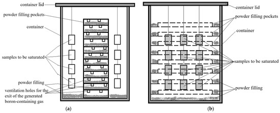
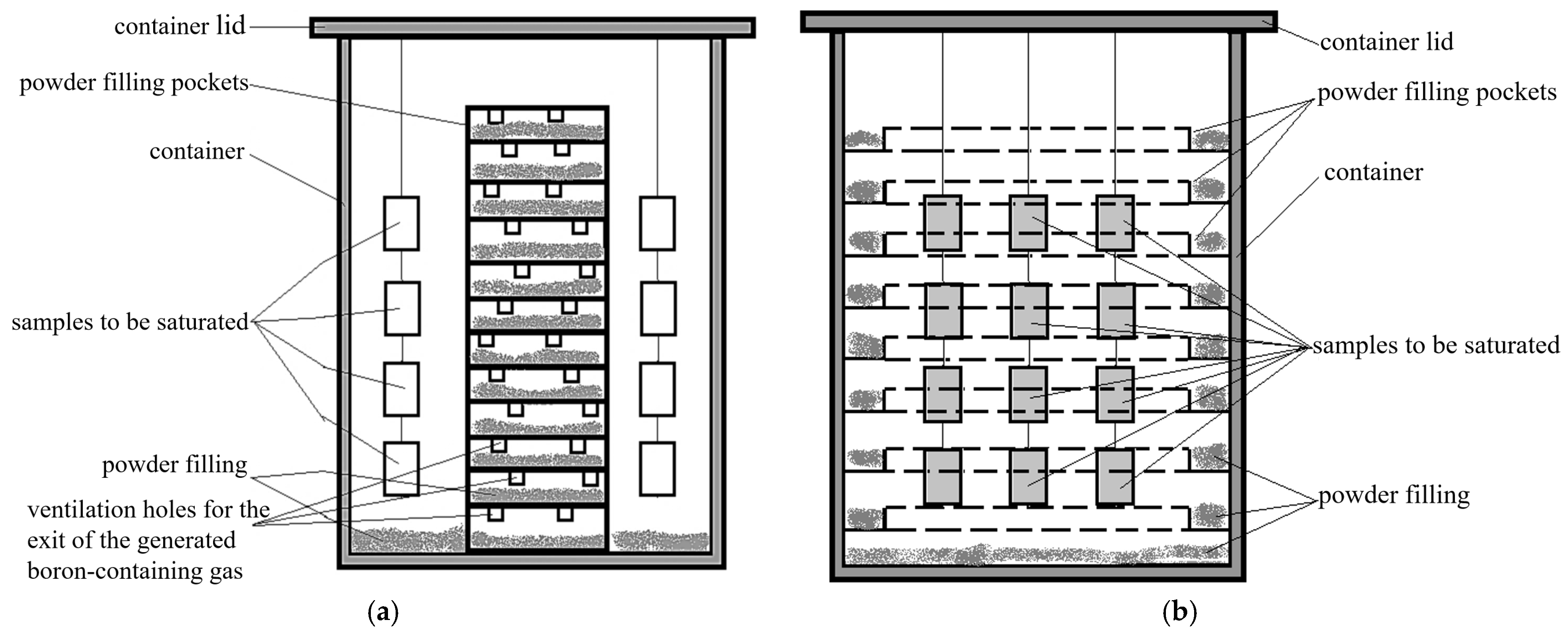
To improve the efficiency of gas-phase boriding and enhance the thickness, dimensional accuracy, and reliability of the diffusion coating, a new sealed-container structure for gas-phase boriding was proposed in this study. Compared with the previously used container, the arrangement of the powder layer used to generate the boron-containing gas was modified in the new container. Specifically, the powder holders were designed as pocket structures distributed along the container wall, rather than being arranged along the central axis as recommended in Ref. [34] (see Figure 1). The air inside the sealed container can be replaced with ultra-high-purity argon, or the container can first be filled with argon and then evacuated to 10 Pa. This structure was designed based on the following considerations:
Figure 1.
Schematic representation of containers: (a) a container manufactured in accordance with the recommendations in [34]; (b) a container subsequently manufactured based on the results of preliminary experiments.
- -
- Given that the container is airtight, heating its interior is only possible through radiation from the heated container walls toward the interior volume, as well as through convective transport by the gas phase; therefore, placing the powder charge as close as possible to the container walls will accelerate the heating of the powder charge and the onset of active boron-containing gas generation, which will further intensify the heating of the container’s interior.
- -
- Placing the powder filling in narrow pockets located along the inner perimeter of the container will heat the powder mixture more evenly, thus intensifying the generation of active gases; furthermore, this ensures more complete utilization of the powder and increases the intensity of the saturation process and the overall efficiency of the process.
- -
- Since the pockets located on the inner walls of the container do not require special openings for the generated gas to escape, they can be arranged more densely but made narrower, which allows for a greater number of samples to be placed in the container’s reaction chamber (see Figure 1).
- -
- This structure can be applied to both single- and multicomponent boron saturation.
2. Materials and Methods
Boriding treatments were carried out using both the sealed-container structure proposed in this study and the conventional container structure, as shown in Figure 1. The experimental results obtained by the two structures were then compared.
The boriding medium used in this study was a powder filling containing boron, chromium, and titanium, with the following composition: 50% B4C + 20% CrB2 + 15% TiB2 + 5% NaF + 7% NH4Cl + 3% Al2O3. All components are given in mass fractions. The containers were filled with ultra-high-purity argon at atmospheric pressure. In each experiment, five samples made of 45# steel (chemical composition listed in Table 1) were used for the boriding experiments. After boriding, all samples were examined to verify the presence of the diffusion coating and were subjected to metallographic investigation.
Table 1.
Chemical composition of 45# steel used in this study (wt.%).
The hermetically sealed containers were placed in a chamber furnace preheated to 950 °C. The heating time was 0.4–0.5 h, and the temperature was monitored using a thermocouple placed inside the containers. After heating the containers to 950 °C, they were held at this temperature for 3 h, after which they were removed from the furnace and cooled in air. After cooling was complete, the containers were opened, the samples were removed, and metallographic templates were cut from them using a “MICRACUT-201(Metkon instruments Inc., Bursa, Turkey)” precision cutting machine. Cutting was performed under intensive water cooling, and the cutting parameters were selected so as not to introduce distortions into the sample being cut. The cut templates were embedded in an epoxy compound using a “METAPRESS (Metkon Instruments Inc., Bursa, Turkey)” metallographic press, then ground and polished on a “DIGIPREP (Metkon instruments inc., Bursa, Turkey)” automatic grinding and polishing machine according to previously described methods [47,48,49]. To study the macro- and microstructures of the samples, the “Thixomet PRO (V 4.0.0012, Thixomet LLC, Saint-Petersburg, Russia)” hardware and software system was used, which includes a Carl Zeiss Axio Observer Z1m metallographic microscope (Carl Zeiss AG, Oberkochen, Germany); the study was conducted according to existing methods [49,50,51,52,53,54]. A 4% solution of nitric acid in ethyl alcohol was used as an etchant for microstructure identification, and microhardness measurements were performed on an MN-6 universal hardness tester (Metkon Instruments Inc., Bursa, Turkey) at a load of 100 g (0.98 N). Surface roughness was measured using a Model 130 mechanical profilometer (JSC Proton Plant, Zelenograd, Moscow, Russia) on flat surfaces measuring 10 × 30 mm. Five linear measurements were taken along a 25 mm line on each specimen. The data obtained were averaged, and the resulting value was taken as the final result. Rectangular samples measuring 10 × 30 × 50 mm were used as test specimens, and their surfaces were polished prior to saturation to a roughness of no more than Rz = 0.12 μm. The samples were measured using a Carl Zeiss Contura G2 coordinate-measuring machine (Carl Zeiss AG, Oberkochen, Germany) with an accuracy of ±2.2 μm. Each sample was measured at least three times, and the average value was calculated and accepted as the final result.
3. Results
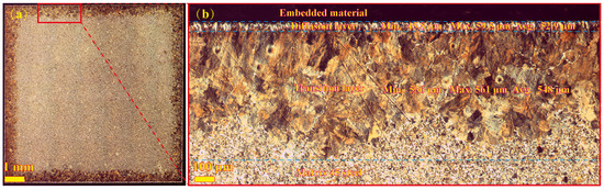
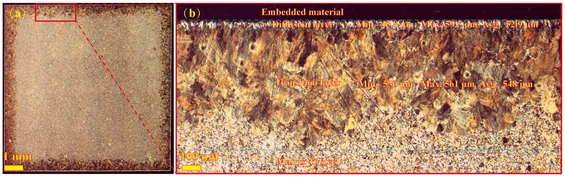
Figure 2 and Figure 3 present the results of the morphological and microstructural analysis of the coating obtained during saturation in a sealed container with the proposed design, a schematic of which is shown in Figure 1a.
Figure 2.
General view of the microstructure of the 45# steel sample after saturation: (a) Cross-section. (b) Diagram illustrating the measurement of key parameters of the diffusion coating—the thickness of the diffusion layer and the transition zone—using the standard tools in Thixomet Pro software. In this case, saturation was performed at normal (atmospheric) pressure in a sealed container manufactured according to Figure 1a and filled with argon prior to saturation.
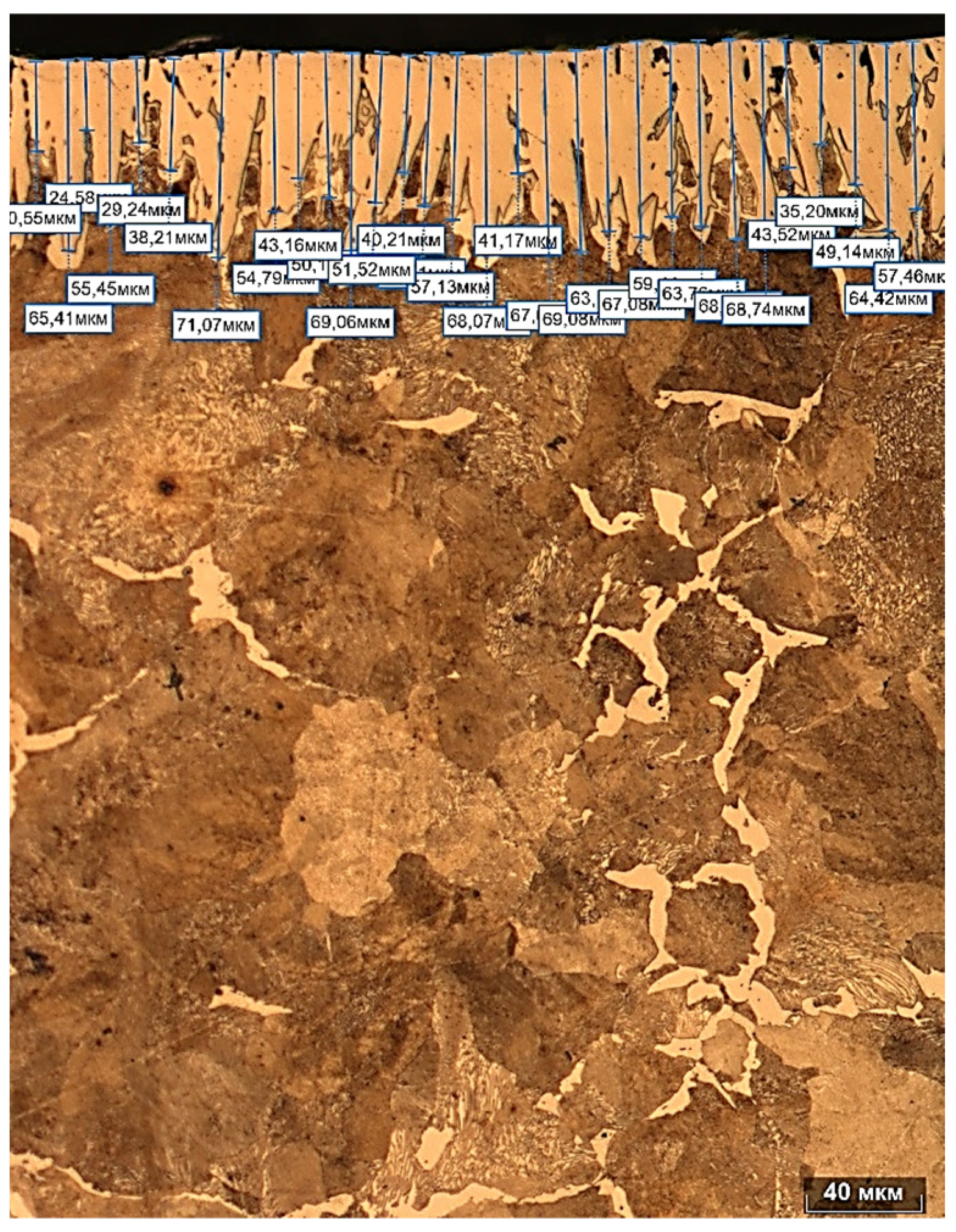
Figure 3.
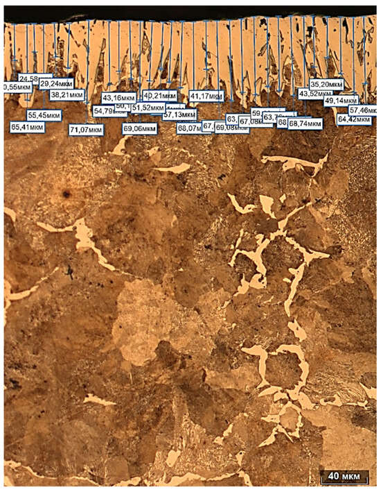
Microstructure of the boride layer and results of manual boride needle length measurements.
As can be seen in Figure 2, the boride layer and the transition zone are distributed uniformly around the entire perimeter of the sample (Figure 1a). The boride layer has an average thickness of 52.9 μm, with minimum and maximum thicknesses of 45.8 and 59.5 μm, respectively. The transition zone consists primarily of pearlite, which formed as a result of downward carbon diffusion from the sample surface as it was displaced by diffusing boron. The average thickness of the transition zone was 548 μm, with minimum and maximum values of 536 and 561 μm, respectively. In addition to the automated determination of the boride-layer thickness, manual measurements were performed using a standard method: the length of the boride needles was measured using a microstructure photograph, after which the arithmetic mean was calculated. The results of the manual boride-layer thickness measurements are presented in Figure 3. It should be noted that the automated measurement method is only possible on microstructure photographs taken at low magnifications, where the boride diffusion layer is generally distinguishable, without structural or morphological features: the microstructure images shown in Figure 2a were obtained in panoramic mode at a 50× optical magnification.
In cases where the morphological features of the diffusion layer become discernible in the coating image, the error begins to increase in “Thixomet Pro” when determining the thickness of the boride coating; this is due to uncertain recognition and errors in distinguishing the boride phase from other structural components (e.g., ferrite) that have a very similar color to the borided ferrite deposits at the edges of the boride needles. According to the manual measurements of boride-layer thickness, an average value of 54.0 ± 13.5 μm was obtained, with a total of 30 measurements taken. Comparing the average thickness of the diffusion layer obtained via automatic measurement using “Thixomet Pro” software and the measurement obtained manually, it can be noted that the values practically coincide with each other, with a correlation coefficient of 0.96. Analyzing the results of the first experiment demonstrated the fundamental feasibility of performing diffusion boriding of steels and alloys in closed, hermetically sealed chambers, provided that an active boron-containing gas phase is generated from a powder charge placed in the reaction vessel. In this case, the resulting diffusion layers exhibit all the characteristics typical of borides, and on 45# steel, the average boride thickness is 54 μm. This thickness already corresponds to the working thickness, and given that this method is recommended primarily for boride coatings on precision parts, as well as on parts with particularly high requirements for the accuracy and roughness of working surfaces, a boride-layer thickness of 54 μm will not only be sufficient for a boride coating but, in some cases, will also allow for a significant reduction in surface roughness if necessary, for example, through polishing with diamond pastes and suspensions.
This series of experiments demonstrated the complete reproducibility of the saturation process itself, as well as the reliability of the developed gas boriding technology. At the same time, they identified potential avenues for further improving the saturation process, both in terms of feasibility and reliability, and in terms of enhancing the properties of the resulting diffusion boride layer. The experiments on gas saturation with varying durations showed that the saturation process begins no sooner than 1–2 h after placing the sealed container in a furnace preheated to 950 °C, and the container-heating process takes approximately 0.4–0.5 h (data obtained from a thermocouple mounted inside the container). Thus, the diffusion saturation process can be defined as a sequentially developing multi-stage process comprising the following main stages: heating the container to the saturation temperature → heating the interior volume of the container to the saturation temperature → heating the powder charge, leading to the generation of an active gas atmosphere → accumulation of active boronizing gas, its heating and mixing, and the onset of the diffusion saturation process. Thus, based on an analysis of the process’s phased nature, it is reasonable and logical to assume that although heating the container to the saturation temperature takes an average of 0.45 h, additional time is required to heat the powder charge to the required temperature, since the stack of pockets containing the powder charge, located in the center of the sealed container, heats up primarily due to radiative heat transfer; other heat transfer mechanisms during the heating stage appear to make a minor contribution. The experimental studies conducted by placing a thermocouple measuring junction in the pockets containing the mixture being heated confirmed the following assumptions: after the reactor was placed in a furnace preheated to the required temperature, heating of the powder charge was achieved in the lower pocket after approximately 0.7 h, and in the upper pocket after 0.8–1.1 h, whereas the pockets located in the middle section heated up after approximately 1.2–1.5 h. Thus, analyzing and experimentally verifying the saturation conditions suggested that the powder-filled pockets should be arranged in the form of disk rings in contact with the inner wall of the reactor. First, this arrangement will reduce the usable reactor volume occupied by the pockets, allowing for an increase in the reactor’s usable loading capacity with parts to be saturated, or an increase in the size of the parts to be saturated, without changing the container’s dimensions. Second, the placement of the powder-filled pockets directly adjacent to the heated walls will accelerate the heating of the powder and, consequently, the onset of active gas generation. In turn, the generation of an active gas environment will intensify and accelerate the heating of the reaction space—due to increased thermal conductivity of the gas atmosphere in the reaction space as the gas pressure inside it rises—and simultaneously intensify convective heat transfer. Thus, placing pockets filled with powder along the inner wall of the container will enable the following:
- Optimizing the reaction space by increasing its usable volume;
- Accelerating the heating time of the entire container and, consequently, reducing the time to the start of the saturation process;
- Reducing the volume of powder feed used per batch while increasing its utilization efficiency.
Repeating the gas-phase boronizing experiments in the upgraded sealed container (see Figure 1b) confirmed the conclusions drawn from the results of the earlier analyses. According to measurements of the powder charge heating time, in the upgraded container, the powder mixture heated up uniformly throughout the entire volume and in each pocket simultaneously; the time required for the powder charge to reach a temperature of 950 °C decreased from 1.1 h (average time) to approximately 0.85 h, counting from the moment the reactor was placed in the preheated furnace. In addition, according to thermometric data, a temperature of 950 °C at the geometric center of the reactor was reached in approximately 0.85–0.9 h. These experiments indicate that the onset of saturation in the container with the optimized design is guaranteed to occur after 1 h of holding, counting from the moment the reactor is placed in the preheated furnace: a layer with a thickness of 1 to 3 μm is clearly observed on the extracted samples. Based on the results of preliminary experiments to determine the reactor heating time, it was decided to reduce the saturation time in the reactor with the optimized design from 3 h to 1.5 h, i.e., by half. At the same time, the total high-temperature holding time, including the heating and saturation stages, was reduced from 3.5 h to 2 h, or by a factor of 1.75. The specific consumption of powder feedstock decreased from 0.6 kg of powder per liter of reactor volume to 0.5 kg of powder per liter of reactor volume. The results of the gas saturation experiment in the optimized (according to Figure 1b) reactor are presented in Figure 4.
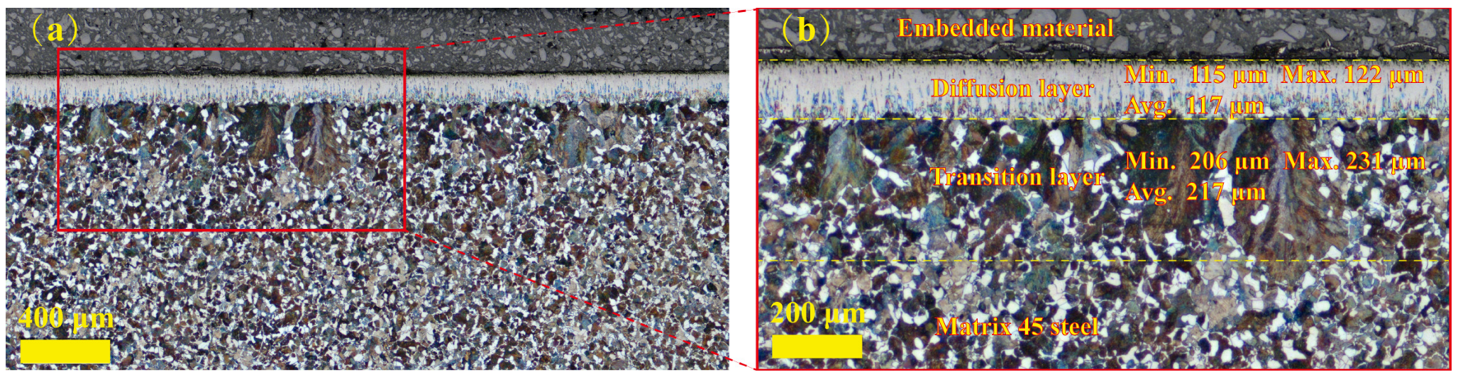
Figure 4.
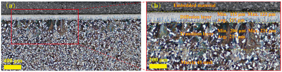
General view of the boride coating on 45# steel after saturation: (a) Cross-section. (b) Diagram illustrating the measurement of key parameters of the diffusion coating—the thickness of the diffusion layer and the transition zone—measured using the standard tools in “Thixomet Pro” software. In this case, saturation was performed at normal (atmospheric) pressure in a sealed container fabricated according to Figure 1b and filled with argon prior to saturation.
Figure 4, which shows the microstructure of the boride layer and transition zone, demonstrates that the boride-layer thickness obtained using the optimized wall-pocket container increased to 117 μm. Compared with the average boride-layer thickness of 54 μm obtained using the conventional centrally powder-filled container, this represents a 2.16-fold increase. Meanwhile, the thickness of the transition zone decreased significantly from 548 μm to 217 μm, corresponding to a 2.5-fold reduction. This inverse change directly reflects the acceleration of the diffusion process.
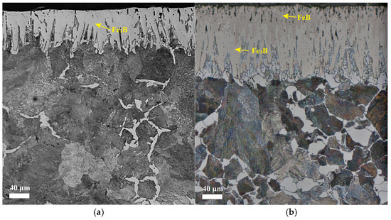
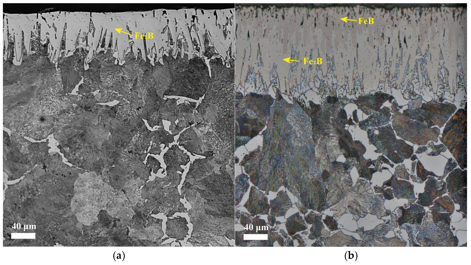
Figure 5 shows the cross-sectional metallographic morphologies of the borided coatings obtained using the two container structures. As shown in Figure 5a, when the conventional centrally powder-filled container was used, the borided layer etched with a nitric acid alcohol solution exhibited a single-phase Fe2B structure. Its needle-like or columnar grains were relatively coarse and loosely arranged, with clear grain boundaries but a less developed interface. In contrast, when the new wall-pocket container was used, as shown in Figure 5b, the coating formed a distinct duplex saw-tooth structure, with an FeB phase in the surface layer (indicated by a slightly darker region) and an Fe2B phase in the subsurface layer. The interface between the two phases was interlaced, and the needle-like structure was thinner, denser, and more compact, forming a highly developed interfacial network. The acceleration of diffusion can be understood from two aspects. First, the powder-bed reaction in the new wall-pocket container was more intense, generating a larger amount of active boron-containing gas and increasing its partial pressure, thereby enhancing surface adsorption and accelerating the bulk diffusion of boron. Second, as mentioned above, the boride layer formed in the new wall-pocket container exhibited a finer needle-like structure and a more developed interfacial network, as shown in Figure 5b. It is well known that diffusion along phase boundaries and structural units primarily proceeds through a surface-diffusion mechanism, and its rate can be two to four orders of magnitude higher than that of bulk diffusion [55,56,57,58,59,60,61,62,63,64,65,66]. Therefore, a more developed interface facilitates more efficient boron migration and ultimately promotes the formation of a thicker boride layer. The thinning of the transition zone should be considered in terms of carbon behavior. Enhanced boron diffusion promotes the accelerated inward “displacement” of carbon atoms at the growth front of the boride layer. However, the diffusion rate of carbon itself does not increase to the same extent as a result of the mechanical compression caused by the boride layer. Under the combined effect of these two factors, the cementite plates precipitated in the transition zone become more dispersed. This not only increases the hardness of this region, but also makes the dispersed cementite, containing 6.67 wt.% carbon, a more effective carbon reservoir. However, because the carbon diffusion rate remains essentially constant, the transition zone cannot thicken accordingly; instead, it tends to become thinner as the boride layer becomes denser.
Finally, the total thickness of the diffusion coating, including both the boride layer and the transition zone, was approximately 600 μm in the conventional centrally powder-filled container shown in Figure 1a, and approximately 335 μm in the new wall-pocket container shown in Figure 1b. This significant difference is consistent with the above changes in diffusion kinetics.
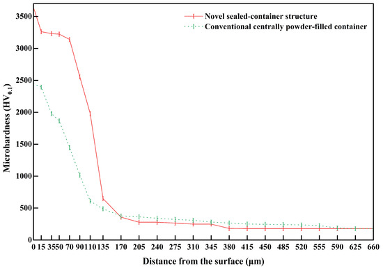
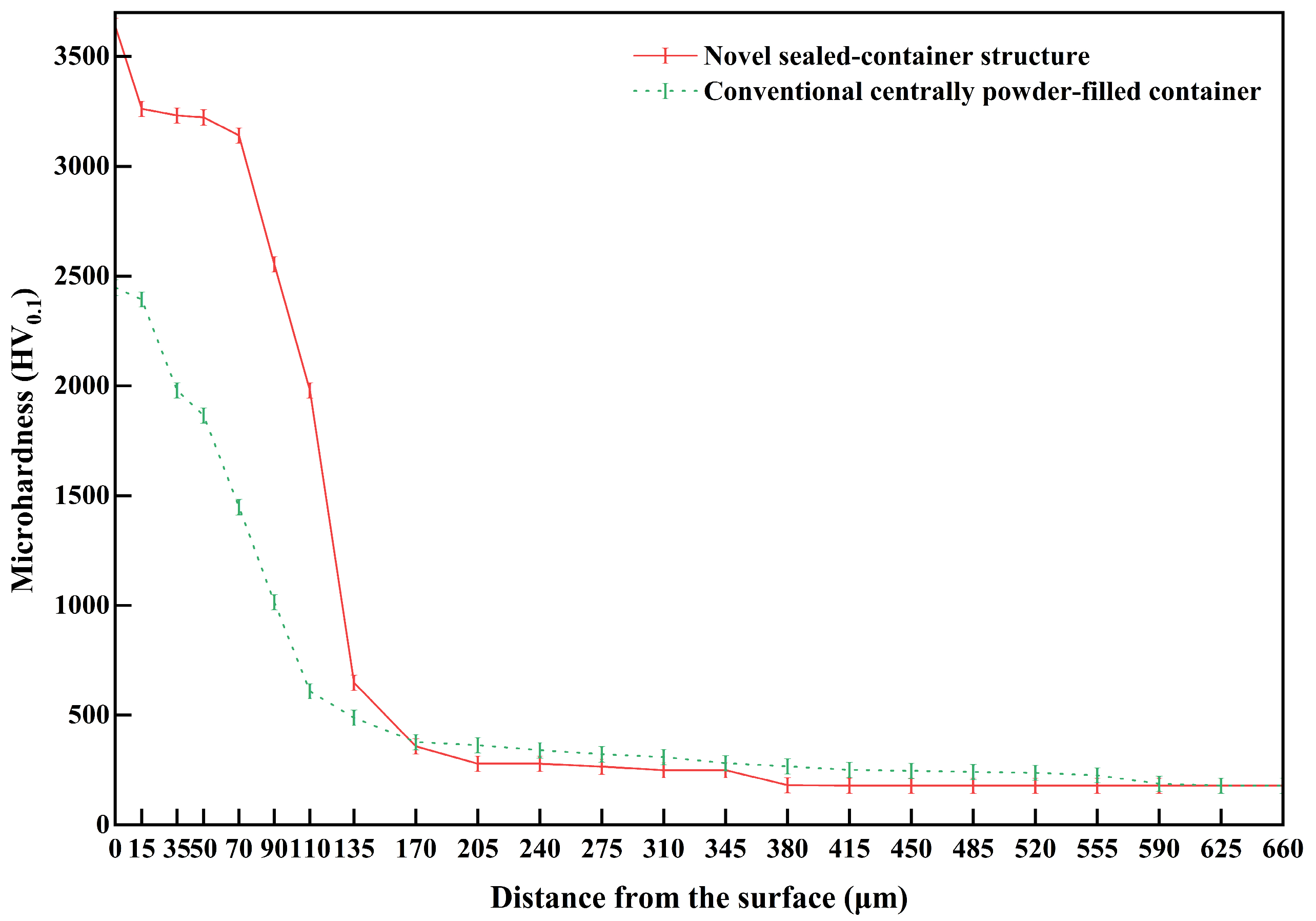
Figure 6 shows the microhardness distribution profile of the diffusion layer, including the boride layer and the transition zone.
Figure 6.
Microhardness distribution across the cross-section of a diffusion coating obtained by gas-phase saturation in the containers shown in Figure 1.
The microhardness distribution curves in Figure 6 demonstrate that the hardness variation trend of the boride layer is generally consistent with the boride-layer thickness shown in the corresponding microstructural observations. It is evident that the hardness of the boride layer obtained in the new wall-pocket container is approximately 1.5 times higher than that obtained in the conventional centrally powder-filled container. This is mainly attributed to the different surface microstructures of the two boride layers: the coating formed in the new wall-pocket container consists of a dual-phase layer, with FeB in the outer layer and Fe2B in the sublayer, whereas the coating obtained in the conventional centrally powder-filled container is composed of a single Fe2B phase. Meanwhile, the measured microhardness values of the boride layers under both conditions exceed the typical values of pure Fe2B, approximately 1600 HV, and pure FeB, approximately 2100 HV. This can be attributed to the use of a three-component boron–chromium–titanium co-doping powder feedstock in this study, which promotes the alloying of iron borides with chromium and titanium, thereby resulting in higher hardness and toughness [67,68,69,70].
Upon measuring the dimensions of the samples before and after gas saturation using the proposed method, it was found that after saturation, the average increase in sample dimensions was 14 μm, with an average diffusion coating thickness of 117 μm, which is approximately 5% of the layer thickness. Roughness measurements showed that samples with an initial average roughness of Rz = 0.10 μm had an average roughness of Rz = 0.36 μm after saturation, with a matte light-gray tint characteristic of boride coatings. This roughness is sufficient for most applications of parts with increased surface quality requirements.
4. Conclusions
This study demonstrates the feasibility of obtaining boride coatings through simultaneous gas-phase saturation with boron, chromium, and titanium. The saturating medium used in this study was composed of 50% B4C + 20% CrB2 + 15% TiB2 + 5% NaF + 7% NH4Cl + 3% Al2O3, and the coating was formed from the powder filling inside the sealed container. This saturation method eliminates direct contact between the powder material and the surface of the hardened part. The coating obtained by this method does not require additional cleaning or surface washing after saturation. This is particularly important for the hardening of high-precision parts, such as precision fuel-system components and spools, as well as parts with stringent requirements for low surface roughness. The main conclusions are as follows:
- Using the novel sealed-container structure for contactless gas-phase boriding proposed in this study, in which powder-filled pockets are arranged along the container wall, effective multicomponent gas-phase co-saturation with boron, chromium, and titanium was achieved. Under multicomponent saturation conditions, the obtained coating exhibited higher hardness than single-component boride coatings because of the alloying effect of chromium and titanium on iron borides. This container structure can be used not only for single-component boron saturation, but also for multicomponent boron saturation combined with chromium and titanium.
- Gas-phase boriding using the new container accelerated the formation of the diffusion coating from the gas phase. Compared with the conventional centrally powder-filled container, the coating formation process was accelerated by a factor of 2.16. The active gas phase was generated directly by decomposition of the powder medium inside the container, thereby avoiding the use of hazardous and highly toxic boron-containing gases during the gas-phase boriding process.
- Compared with the conventional centrally powder-filled container, the new container produced a diffusion coating with 50% greater thickness and 30–40% higher microhardness. These improvements can be attributed to the arrangement of the powder filling along the inner wall of the sealed container, which enabled the generation of a larger volume of gas phase and thereby promoted the formation of the diffusion coating.
Author Contributions
Conceptualization, A.G. and S.I.; methodology, S.M., Z.H., and M.G.; validation, A.G., S.Z., G.F., and Q.Z.; formal analysis, S.I., M.G., and Z.H.; investigation, M.G., S.I., and S.Z.; resources, S.M. and G.F.; data curation, S.I., M.G., and Z.H.; writing—original draft preparation, S.I., Z.H., and M.G.; writing—review and editing, S.M., Z.H., and A.G.; visualization, Z.H. and S.I.; supervision, S.M., A.G., and Q.Z.; project administration, S.M. and A.G.; funding acquisition, S.M. and G.F. All authors have read and agreed to the published version of the manuscript.
Funding
This research was funded by the “Zhejiang Provincial Leading Innovative and Entrepreneurial Team Program”, grant number 2024R01014; the “Hubei Province Sc. and Tech. Research Plan”, grant number 2023EHA027; the “National Innovation Base plan”, grant number 111HTE2022002.
Data Availability Statement
The original contributions presented in this study are included in the article. Further inquiries can be directed to the corresponding authors.
Acknowledgments
The authors thank the participating laboratories for their support during this study.
Conflicts of Interest
Author Mikhail Guryev was employed by the company Zhejiang Briliant Refrigeration Equipment Co., Ltd. The remaining authors declare that the research was conducted in the absence of any commercial or financial relationships that could be construed as a potential conflict of interest.
References
- Zhai, W.; Bai, L.; Zhou, R.; Fan, X.; Kang, G.; Liu, Y.; Zhou, K. Recent Progress on Wear-Resistant Materials: Designs, Properties, and Applications. Adv. Sci. 2021, 8, 2003739. [Google Scholar] [CrossRef] [Scilit] [PubMed]
- Jose, S.A.; Lapierre, Z.; Williams, T.; Hope, C.; Jardin, T.; Rodriguez, R.; Menezes, P.L. Wear- and Corrosion-Resistant Coatings for Extreme Environments: Advances, Challenges, and Future Perspectives. Coatings 2025, 15, 878. [Google Scholar] [CrossRef] [Scilit]
- Wang, Y.; Feng, C.; Lin, T.; Zhu, R.; Zhang, J.; Yang, H.; Yi, S.; He, J.; Tu, M.; Wei, G. A Review of Wear-Resistant Coatings for Steel Substrates: Applications and Challenges. Metals 2025, 15, 1231. [Google Scholar] [CrossRef] [Scilit]
- Tejero-Martin, D.; Rezvani Rad, M.; McDonald, A.; Hussain, T. Beyond Traditional Coatings: A Review on Thermal-Sprayed Functional and Smart Coatings. J. Therm. Spray Technol. 2019, 28, 598–644. [Google Scholar] [CrossRef] [Scilit]
- Abadias, G.; Chason, E.; Keckes, J.; Sebastiani, M.; Thompson, G.B.; Barthel, E.; Doll, G.L.; Murray, C.E.; Stoessel, C.H.; Martinu, L. Review Article: Stress in Thin Films and Coatings: Current Status, Challenges, and Prospects. J. Vac. Sci. Technol. A 2018, 36, 020801. [Google Scholar] [CrossRef] [Scilit]
- Fardan, A.; Berndt, C.C.; Ahmed, R. Numerical Modelling of Particle Impact and Residual Stresses in Cold Sprayed Coatings: A Review. Surf. Coat. Technol. 2021, 409, 126835. [Google Scholar] [CrossRef] [Scilit]
- Ambiger, K.D.; Murthy, B.R.N.; Hiremath, P.; Shivamurthy, R.C.; Kowshik, S.; Naik, N.; Jain, P.; Arunkumar, H.S. Influence of gas carburization on the microstructure, mechanical properties, and behavior of alloying elements in plain and alloyed low-carbon steels. Mater. Res. Express 2025, 12, 046507. [Google Scholar] [CrossRef] [Scilit]
- Horn, A.; Merklein, M. Bending behavior of a hot-stamped complex-phase steel with tailored properties by local carburization. IOP Conf. Ser. Mater. Sci. Eng. 2021, 1157, 012011. [Google Scholar] [CrossRef] [Scilit]
- Yang, Y.-H.; Wang, M.-Q.; Chen, J.-C.; Dong, H. Microstructure and Mechanical Properties of Gear Steels After High Temperature Carburization. J. Iron Steel Res. Int. 2013, 20, 140–145. [Google Scholar] [CrossRef] [Scilit]
- Peng, Y.; Gong, J.; Rong, D.; Jiang, Y.; Fu, M.; Yu, G. Numerical analysis of low-temperature surface carburization for 316L austenitic stainless steel. Acta Metall. Sin. 2015, 51, 1500–1506. [Google Scholar] [CrossRef]
- Zuo, J.; Wang, W.; Zhang, X. Study on vacuum gas nitriding process and surface properties of AISI 430 stainless steel. Surf. Sci. Technol. 2026, 4, 10. [Google Scholar] [CrossRef] [Scilit]
- Ranaware, P.G. Effect of Thermal Cycling on Nitriding of Maraging Steel 18Ni-250. J. Mater. Eng. Perform. 2025, 34, 27447–27460. [Google Scholar] [CrossRef] [Scilit]
- Skołek, E.; Wasiak, K.; Chmielarz, K.; Marciniak, S.; Pawluk, P.; Osuch-Słomka, E.; Wierzchoń, T. Low-temperature glow discharge nitriding of nanobainitic X37CrMoV5-1 steel: Surface and core properties. J. Mater. Res. Technol. 2026, 41, 3999–4014. [Google Scholar] [CrossRef] [Scilit]
- Sklizkov, I.D.; Vafin, R.K. Comparative analysis of electrolytic-plasma and ion nitriding of high-speed steel P6M5. Mater. Technol. Des. 2025, 7, 16–23. [Google Scholar] [CrossRef] [Scilit]
- Reddy, C.A.K.; Rao, P.K.V.; Venkatesh, B.; Rao, B.N. Influence of liquid nitriding on the surface layer of M50 NiL steel for bearing applications. J. Mech. Behav. Mater. 2025, 34, 20250050. [Google Scholar] [CrossRef] [Scilit]
- Kozlov, E.V.; Malinovskaya, V.A.; Popova, N.L.; Sizonenko, N.R.; Gromov, V.E. Formation of structure-phase states in gradient layers of 20X2H4A steel after nitrocementation. Steel Transl. 2007, 37, 986–988. [Google Scholar] [CrossRef] [Scilit]
- Bakhracheva, Y.; Vasilyev, A.; Petikova, T. Solution to the Diffusion Problem in the Thermocyclic Nitrocementation of Steel. Mater. Sci. Forum 2016, 870, 545–549. [Google Scholar] [CrossRef] [Scilit]
- Kolmykov, V.I.; Kostin, R.Y.; Vorobyev, Y.S.; Kolmykov, D.V. On the Use of Repeated Low-Temperature Nitrocementation for Effective Hardening of the Crankshafts of KAMAZ Vehicles, Ground to Repair Dimensions. Proc. Southwest State Univ. Ser. Eng. Technol. 2023, 13, 70–85. (In Russian) [Google Scholar] [CrossRef] [Scilit]
- Jornsanoh, P.; Chankitmunkung, S.; Taweejun, N.; Praditja, T.; Diewwanit, O. Effect of Nitrocarburizing and Tempering on Microstructure and Wear Performance of SKH51 High-Speed Tool Steel. J. Mater. Eng. Perform. 2026, 35, 23493–23509. [Google Scholar] [CrossRef] [Scilit]
- Rao, B.V.S.; Vijey, I.; Srinivasulu, K.; Țălu, Ș.; Patra, N. Low-temperature plasma nitrocarburizing of 15 − 5 PH stainless steel for optimized surface hardness and corrosion resistance. J. Mater. Sci. Mater. Eng. 2025, 20, 149. [Google Scholar] [CrossRef] [Scilit]
- Zhang, H.; Zhang, Y.; Jin, L.; Zhang, B.; Zhang, Y. Investigation on Microstructure, Thermal Fatigue Resistance, and Tribological Behavior of Mo2FeB2-Based Cermet Coating on GCr15 Steel Substrate. Lubricants 2026, 14, 5. [Google Scholar] [CrossRef] [Scilit]
- Gómez-Vargas, O.; Ortiz-Domínguez, M.; Melo-Máximo, L.; Melo-Máximo, D.; Escalona-Cambray, F.; Solis-Romero, J. A Microstructure Comparison of TiN with a Cr Metallic Interlayer and Boride Layers Formed on AISI 304 Steel: Wear Properties. Microsc. Microanal. 2020, 26, 2216–2218. [Google Scholar] [CrossRef] [Scilit]
- Dybkov, V.I.; Sidorko, V.R.; Goncharuk, L.V.; Khoruzha, V.G.; Samelyuk, A.V. Microstructure, Growth Kinetics, and Abrasive Wear Resistance of Boride Layers on Fe–30% Cr Alloy. Powder Metall. Ceram. 2013, 51, 518–530. [Google Scholar] [CrossRef] [Scilit]
- Beznák, M.; Chaus, A.S.; Čaplovič, L. Microstructure and Properties of Diffusion Boride Layer on Die Steel. Defect Diffus. Forum 2011, 312–315, 788–793. [Google Scholar] [CrossRef] [Scilit]
- Bünyamin, Y. Investigation of the microstructure, hardness and corrosion behavior of AISI 4340 steel subjected to pack boronizing process. Metall. Res. Technol. 2026, 123, 110. [Google Scholar] [CrossRef] [Scilit]
- Gürcan, Y.; Işıtan, A. Determination of The Optimum Surface Roughness of AISI D2 Cold Work Tool Steel for Industrial Boronizing Applications. Osman. Korkut Ata Üniv. Fen Bilim. Enst. Derg. 2025, 8, 2094–2110. [Google Scholar] [CrossRef] [Scilit]
- Katasho, Y.; Oishi, T.; Haarberg, G.M. Electrochemical Formation of Calcium Hexaboride and Boronizing of Metal Electrodes in CaCl2-Based Molten Salt. Met. Mater. Trans. B 2024, 55, 266–277. [Google Scholar] [CrossRef] [Scilit]
- Shen, Y.; Yu, D.; Liu, X.; Cheng, H. Novel Cathode Plasma Electrolysis for Rapid Fabrication of a Boronizing Layer on Ti–6Al–4V Titanium Alloy: Enhanced Wear Resistance and Microstructural Characterization. Adv. Eng. Mater. 2025, 27, 2500731. [Google Scholar] [CrossRef] [Scilit]
- Zhu, S.L.; Liu, Y.; Wu, C.J.; Zhu, X.Y.; Su, X.P. Effect of surface boronizing on the zinc corrosion resistance of Fe-20Cr-5B-3Al alloy. Mater. Werkst. 2025, 56, e70032. [Google Scholar] [CrossRef] [Scilit]
- Ferreira, L.M.; Cardoso, R.P.; D’Oliveira, A.S.C.M. Niobium Boronizing: Influence of the Treatment Temperature and Time. Mater. Perform. Charact. 2023, 12, 366–375. [Google Scholar] [CrossRef] [Scilit]
- Kusuhara, T.; Morimoto, J.; Abe, N.; Tsukamoto, M. Laser Boronizing of Stainless Steel with Direct Diode Laser. J. High Temp. Soc. 2010, 36, 295–299. [Google Scholar] [CrossRef] [Scilit]
- Muhammad, Y.K.; Abdullah, B.; Idham, M.F.; Saad, N.H. The Effects on Microstructure and Hardness of 0.28% Vanadium and 0.87% Nickel Alloyed Ductile Iron after Boronizing Process. Key Eng. Mater. 2017, 740, 65–69. [Google Scholar] [CrossRef] [Scilit]
- Kulka, M. Current Trends in Boriding: Techniques; Springer Nature: Cham, Switzerland, 2019; 298p. [Google Scholar] [CrossRef] [Scilit]
- Pengxun, Y. Gaseous boronizing with solid boron-yielding agents. Thin Solid Films 1992, 214, 44–47. [Google Scholar] [CrossRef] [Scilit]
- Nam, K.-S.; Lee, K.-H.; Lee, D.Y.; Song, Y.-S. Metal surface modification by plasma boronizing in a two-temperature-stage process. Surf. Coat. Technol. 2005, 197, 51–55. [Google Scholar] [CrossRef] [Scilit]
- Dearnley, P.A.; Farrell, T.; Bell, T. Developments in plasma boronizing. J. Mater. Energy Syst. 1986, 8, 128–131. [Google Scholar] [CrossRef] [Scilit]
- Küper, A.; Qiao, X.; Stock, H.; Mayr, P. A novel approach to gas boronizing. Surf. Coat. Technol. 2000, 130, 87–94. [Google Scholar] [CrossRef] [Scilit]
- Kulka, M.; Makuch, N.; Pertek, A.; Piasecki, A. An alternative method of gas boriding applied to the formation of borocarburized layer. Mater. Charact. 2012, 72, 59–67. [Google Scholar] [CrossRef] [Scilit]
- Yi, M.; Deng, B.; Xiao, H.; Wei, Q.; Ma, L.; Zhou, K.; Luo, Y.; Li, L.; Zhang, L.; Yu, Z. Gaseous boronizing pretreatment for the deposition of nanocrystalline diamond films on cemented carbide substrates. Mater. Res. Express 2019, 6, 076404. [Google Scholar] [CrossRef] [Scilit]
- Zemlyakov, S.A.; Guryev, A.M.; Guryev, M.A.; Ivanov, S.G. Method for the Chemical-Thermal Treatment of Fuel System Components. Patent RU 2752689, 29 July 2021. [Google Scholar]
- Ivanov, S.G.; Guriev, M.A.; Augstkalns, A.I.; Zemlyakov, S.A.; Guriev, A.M. Development of a gas boriding technology in closed volumes. Polzunovsky Vestn. 2022, 2, 193–199. [Google Scholar] [CrossRef] [Scilit]
- Augstkaln, A.I.; Ivanov, S.G.; Guriev, M.A.; Guriev, A.M.; Zemlyakov, S.A. Method for Chemical-Thermal Treatment of Precision Parts. Patent RU 2805687, 23 October 2023. [Google Scholar]
- Guriev, M.A.; Ivanov, S.G.; Guriev, A.M.; Lygdenov, B.D. Formation of a diffusion layer on steel 45 with simultaneous saturation with boron, chromium, and titanium. Polzunovskiy Vestn. 2021, 218–224. (In Russian) [Google Scholar] [CrossRef] [Scilit]
- Hariharan, R.; Balasundaram, R.; Lenin, K.; James, D.J.D. Enhancing the surface characteristics of Nitronic-50 through pack boronizing. Chem. Pap. 2025, 79, 4303–4316. [Google Scholar] [CrossRef] [Scilit]
- Malakhov, D.V.; DeBoer, A.A. Thermodynamic Aspects of Powder-Pack Boronizing. J. Phase Equilib. Diffus. 2024, 45, 367–383. [Google Scholar] [CrossRef] [Scilit]
- Chen, Y.; Chen, G.; Du, C.; Liu, K. Wear-Resistant Boronizing for 17-4PH Components of Fluid Pump. Metals 2024, 14, 1072. [Google Scholar] [CrossRef] [Scilit]
- Jurči, P.; Orihel, P.; Keddam, M.; Vretenár, V.; Maťko, M. Boride layers on high-carbon high-chromium tool steels: Microstructure-mechanical properties relationship. J. Mater. Res. Technol. 2025, 39, 5808–5821. [Google Scholar] [CrossRef] [Scilit]
- Guryev, M.A.; Ivanov, S.G.; Guryev, A.M.; Kosheleva, E.A.; Chernykh, E.V. Identification of the phase composition of boride coatings by color etching methods. Polzunovsky Alm. 2020, 19–23. (In Russian) [Google Scholar]
- Kazakov, A.A.; Murysev, V.A.; Kiselev, D.V. Non-metallic inclusions interpretation technique for factory expertise of metal product defects. CIS Iron Steel Rev. 2021, 22, 41–47. [Google Scholar] [CrossRef] [Scilit]
- Kazakov, A.A.; Ryaboshuk, S.V.; Lyubochko, D.A.; Chigintsev, L.S. Investigation of the origin of nonmetallic inclusions in high-strength low-alloy steel using automated analysis of characteristics. Microsc. Microanal. 2015, 21, 1755–1756. (In Russian) [Google Scholar] [CrossRef] [Scilit]
- Kazakov, A.A.; Kiselev, D. Industrial application of thixomet. Metallogr. Microstruct. Anal. 2016, 5, 294–301. (In Russian) [Google Scholar] [CrossRef] [Scilit]
- Kazakov, A.A.; Kiselev, D. Industrial application of the Thixomet image analyzer for quantitative description of the microstructure of steel and alloys. Microsc. Microanal. 2015, 21, 457. (In Russian) [Google Scholar] [CrossRef] [Scilit]
- Vander Voort, G.F. (Ed.) Metallography and Microstructures. In ASM Handbook; ASM International: Materials Park, OH, USA, 2004; Volume 9. [Google Scholar]
- Voort, G.V.; Kazakov, A.; Pakhomova, O.; Kazakov, A. Evaluation of normal and abnormal grain size distribution. Mater. Accord. Form Charact. 2016, 5, 521–534. (In Russian) [Google Scholar] [CrossRef] [Scilit]
- Mittemeijer, E.J. Fundamentals of Materials Science; Springer International Publishing: Cham, Switzerland, 2021. [Google Scholar] [CrossRef] [Scilit]
- Wakai, F. Fundamentals of Sintering; Springer: Singapore, 2025. [Google Scholar] [CrossRef] [Scilit]
- Doležal, T.D.; Freitas, R.; Li, J. Spectral sampling of boron diffusion in Ni alloys: Cr and Mo effects on bulk and grain boundary transport. Acta Mater. 2025, 305, 121841. [Google Scholar] [CrossRef] [Scilit]
- Duda, F.P.; Forte Neto, F.S.; Fried, E. Modelling of surface reactions and diffusion mediated by bulk diffusion. Philos. Trans. A Math. Phys. Eng. Sci. 2023, 381, 20220367. [Google Scholar] [CrossRef] [Scilit] [PubMed]
- Burshtein, Z.; Sinder, M. Discerning between bulk diffusion and surface crossing in diffusion measurements. J. Appl. Phys. 2004, 97, 033503. [Google Scholar] [CrossRef] [Scilit]
- Revelli, J.A.; Budde, C.E.; Wio, H.S. Bulk-mediated surface diffusion: Return probability in an infinite system. J. Phys. Condens. Matter 2007, 19, 065127. [Google Scholar] [CrossRef] [Scilit]
- Chechkin, A.V.; Zaid, I.M.; Lomholt, M.A.; Sokolov, I.M.; Metzler, R. Bulk-mediated surface diffusion along a cylinder: Propagators and crossovers. Phys. Rev. E 2009, 79, 040105. [Google Scholar] [CrossRef] [Scilit] [PubMed]
- Ochoa-Tapia, J.A.; Del Rio, P.J.A.; Whitaker, S. Bulk and surface diffusion in porous media: An application of the surface-averaging theorem. Chem. Eng. Sci. 1993, 48, 2061–2082. [Google Scholar] [CrossRef] [Scilit]
- Revelli, J.A.; Budde, C.E.; Prato, D.; Wio, H.S. Bulk mediated surface diffusion: Finite bulk case. Eur. Phys. J. B—Condens. Matter 2003, 37, 205–212. [Google Scholar] [CrossRef] [Scilit]
- Flynn, C.P. Why is diffusion in metals and on metal surfaces universal? J. Phys. Condens. Matter 2006, 18, S439–S445. [Google Scholar] [CrossRef] [Scilit] [PubMed]
- Tsong, T. Mechanisms of surface diffusion. Prog. Surf. Sci. 2001, 67, 235–248. [Google Scholar] [CrossRef] [Scilit]
- Ikuma, Y.; Komatsu, W. Interpretation of the difference in surface diffusion coefficients determined by dynamic and static methods. Solid State Ion. 1989, 32–33, 946–949. [Google Scholar] [CrossRef] [Scilit]
- Voroshnin, L.G. Multicomponent Diffusion Coatings; Nauka i Tekhnika: Minsk, Belarus, 1981; 296p. [Google Scholar]
- ASM International Handbook Committee. Surface Engineering. In ASM Handbook; ASM International: Materials Park, OH, USA, 1994; 1056p. [Google Scholar]
- Borisenok, G.V.; Vasilyev, L.A.; Voroshnin, L.G. Chemical-Thermal Treatment of Metals and Alloys; Metallurgiya: Moscow, Russia, 1981; 424p. (In Russian) [Google Scholar]
- Anthymidis, K.G.; Tsipas, D.N.; Stergioudis, E. Boriding of titanium alloys in a fluidized bed reactor. J. Mater. Sci. Lett. 2001, 20, 2067–2069. [Google Scholar] [CrossRef] [Scilit]

Disclaimer/Publisher’s Note: The statements, opinions and data contained in all publications are solely those of the individual author(s) and contributor(s) and not of MDPI and/or the editor(s). MDPI and/or the editor(s) disclaim responsibility for any injury to people or property resulting from any ideas, methods, instructions or products referred to in the content. |
© 2026 by the authors. Licensee MDPI, Basel, Switzerland. This article is an open access article distributed under the terms and conditions of the Creative Commons Attribution (CC BY) license.