


Abstract
This study investigated the relationship between the surface microstructure of pearlite steel wheels and the formation of fatigue cracks during the braking process by using a full-size wheel braking test rig. After fatigue failure, the surface microstructural evolution and fatigue crack initiation and propagation of the wheel sample were systematically analyzed by optical microscope (OM), scanning electron microscope (SEM), and transmission electron microscope (TEM). The results showed that after braking of 1572 cycles, a large number of fatigue cracks formed at the wheel tread, which caused the wheel to break. After fatigue failure, some dark areas formed at the wheel tread, which were composed of Fe3O4 compounds. This indicates that severe oxidation was produced at the wheel tread during braking due to the high temperature. After fatigue failure, a continuous thermal white etching layer (T-WEL) was formed in some areas of the wheel tread, while crescent-shaped T-WEL was found in other areas. The microstructure of the T-WEL was composed of martensite phase. The rapid increase and decrease in temperature at the wheel tread during the braking process caused martensitic transformation at the wheel tread. The hardness of the sample reached to about 900 HV in WEL and it reduced with the increase in distance from the surface. The cracks were initiated from the surface and gradually propagated into the matrix. However, the crack propagation mode in the continuous T-WEL and crescent-shaped T-WEL was different. In the continuous T-WEL, the continuous T-WEL of the wheel can be peeled off during the braking wear process, and then the crack was gradually propagated into the matrix in the T-WEL peeled area. As for the crescent-shaped T-WEL, due to the large hardness difference between T-WEL and pearlite, the crack initiated at the interface between the T-WEL and pearlite and gradually propagated into the matrix.
1. Introduction
Railway transportation exhibits the characterization of safety, low cost and large transportation capacity, and it has become one of the main modes of transportation in the world. The wheels are the most important component of a train, functioning to bear loading, guidance and brake [1]. With the rapid development of high-speed railway transportation in China, the increase in train operating speed and load exhibit challenges to the service safety and durability of the wheels. The tread braking is the main mode to reduce the wheel speed [2]. The wheel tread and the brake shoe is the sliding wear mode during the braking process, which can increase the wheel tread temperature and cause severe plastic strain [3,4]. The rapid variation in temperature and plastic strain at the wheel tread can cause microstructural evolution and induce larger thermal stress at the wheel tread. Under thermos-mechanical load conditions, the microstructural evolution and larger thermal stress can accelerate the fatigue failure of the wheel steel [5,6,7]. With the increasing speed and axle load, the braking force and friction heat of the wheel are increased, which can affect the fatigue resistance of the wheels [8,9].
Many researchers mainly study the effect of the braking shoe materials on the fatigue failure of the wheel. Ghidini et al. [10] studied the effect of shoe materials on the thermos-mechanical damage of the wheel. The results proposed that the austempered cast iron can reduce the wear and thermos-mechanical damage of the wheel. Also, Ghidini et al. [11] found that organic composite shoes can improve the fatigue resistance of the wheel. Shen et al. [12] analyzed the thermal fatigue damage of the train’s wheel-mounted brake disk. The crack propagation in the axial direction is more likely to lead to fatigue failure. The boron nitride exhibits thermally conductive and thermally stable chemical stability, which also is shown in the braking shoe materials [13].
The frequent braking of the wheel and brake shoe, braking pressure, braking speed and the environment of the rail are important factors causing the fatigue failure of the wheel [14,15]. The increase in velocity and pressure can increase the temperature of the braking surface [16]. The investigation of Luo et al. [17] found that low braking pressure, high speed and large speed range can reduce the braking heat of the wheel. The researchers Angella et al. [18] studied the thermal stability of shoe-braked wheel steel by heat treatment. The results found that the properties of the wheel were reduced after heat treatment of 700 °C and 750 °C. Zhang et al. [19] found that the slope gradient can increase the braking heat of the wheel. Su et al. [20] investigated the effect of braking pressure on fatigue damage behavior of the wheel. The results indicated that the increasing braking pressure can increase the wear and temperature, and the fatigue cracks are formed at the subsurface. The investigation of Caprioli et al. [21] found that the repeated braking cycles can lead to the large possibility fatigue failure of wheel. Tian et al. [22] investigated the microstructural evolution of bainite wheel steel after cyclic drag braking. The increasing temperature is an important factor resulting in phase transform and fatigue failure. The research of Wang et al. [23] showed that the friction heat between the wheel and braking pad causes the RCF failure of the wheel. The study of Landström et al. [24] found that the nonuniform friction heat can cause the formation tensile residual stress, which is unfavorable to the wheel service life. The research of Su et al. [25] found that the friction coefficient and the increase in temperature of the wheel–rail are the main factors causing the fatigue failure of the wheel. Many researchers mainly investigate the fatigue damage according to small-scale laboratory tests [26,27,28]. The full-size wheel braking test exhibits significant engineering advantages compared to the small-size wheel braking test. The small-size wheel braking tests are affected by the size effect and cannot fully reproduce the actual contact state between the wheel and the brake shoe, resulting in deviations in contact pressure distribution, interface temperature distribution, and actual service conditions. The thickness of plastic deformation layer and WEL in small-size wheel braking test is relatively thin in comparison to the full-size wheel braking test due to different stress and thermal distributions in different parameter conditions [29]. However, the full-size wheel braking test adopts the real wheel, brake shoe structure and assembly form consistent with the site, which can accurately reproduce the actual braking speed, braking pressure, inertial load and dynamic impact effect. The friction vibration and heat accumulation behaviors during the test process are highly consistent with the line service state. At the same time, the full-size wheel braking test can truly reflect the structural coupling effect of the braking system, can fully reproduce the plastic deformation, thermal fatigue damage and oxidation wear characteristics of the wheel tread, and can effectively avoid the mechanism distortion problem caused by the scaled-down test. Therefore, the full-scale test can provide a more reliable test basis for the performance evaluation of brake pad materials, the optimization of braking matching and the prediction of service life. However, investigation of the microstructural evolution and its effect on the fatigue failure mechanism of the wheel under full-size wheel braking test rig conditions is rare.
In our work, a full-size wheel braking test is conducted to investigate the relation between microstructural evolution and the formation of fatigue cracks of pearlite steel wheels for high-speed trains. The optical microscope (OM), scanning electron microscope (SEM), and transmission electron microscope (TEM) are used to systematically analyze the microstructural characteristics and the fatigue crack initiation and propagation. The relation between the microstructural evolution and fatigue failure mechanism is discussed.
2. Material and Methods
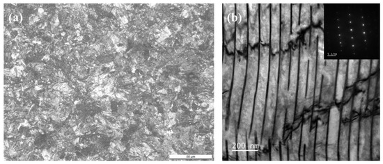
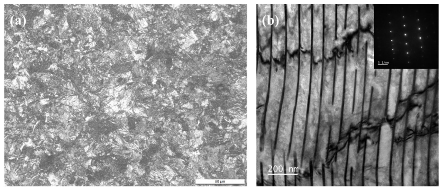
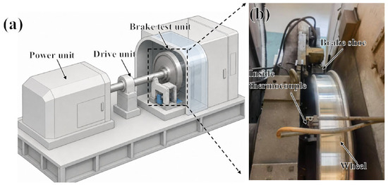
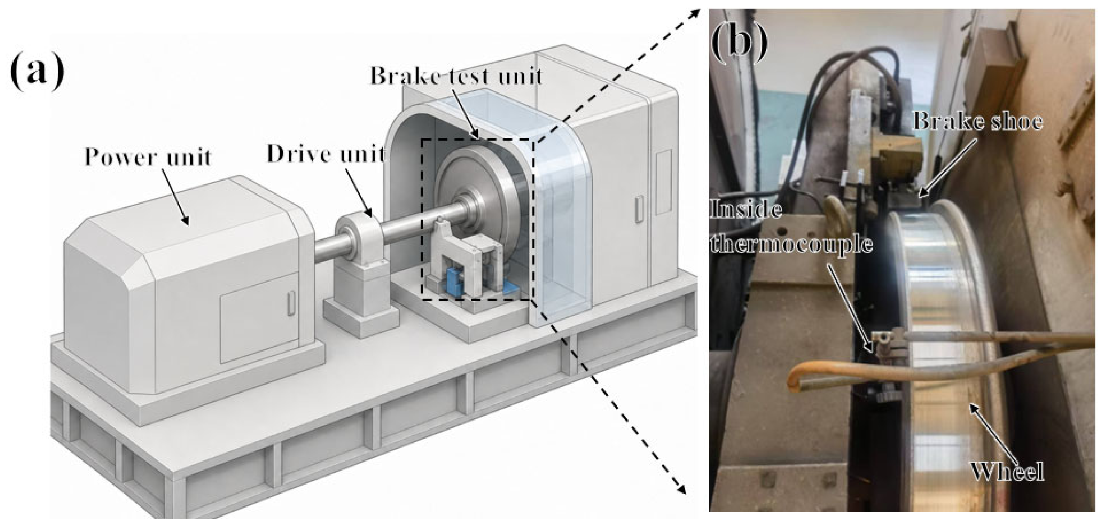
In our work, the test material was a pearlite wheel steel for high-speed trains; its chemical composition is exhibited in Table 1. The initial microstructure of the wheel sample was pearlite and a small amount of proeutectoid ferrite (PF), as shown in Figure 1. LH2 brake shoes were used for bench braking tests, and their material is high-friction synthetic brake shoes. The wheel tread braking test was conducted using a 1:1 wheel-rim braking power test bench, as displayed in Figure 2. During the brake wear test, the axle load of the wheel was 25 t. When the wheel was braked to a stop, the initial speed was 120 km/h, and the wheel brake cycle was 1572 cycles. The sliding wear test was repeated three times, each on a separate wheel specimen.
Table 1.
The chemical composition of the pearlite wheel steel.
Figure 1.
The initial microstructure of the pearlite wheel steel. (a) OM; (b) TEM.
Figure 2.
Full-scale wheel and brake shoe braking dynamic test rig. (a) the schematic diagram of shoe-braking test rig; (b) a magnified partial image of the braking test rig.
After wear, the LEICA DCM3D optical microscope (OM) (LEICA, Wetzlar, Germany) was used to analyze the low magnification of the evolution of the thickness thermal white etching layer (T-WEL) at the cross-section. The wheel sample was first polished and then it was corroded by 4% nitric alcohol. The SUPRA55 scan electron microscope (SEM) (Carl Zeiss AG, Oberkochen, Germany) was used to characterize microstructural evolution in the T-WEL and the initiation and propagation of cracks. The JEM 2100F transmission electron microscopy (TEM) (JEOL Ltd., Tokyo, Japan) was used to characterize the evolution of microstructure in T-WEL, and to determine the type of the T-WEL. The focused ion beam was used to cut the T-WEL area on the surface of the wheel to prepare the TEM sample. The surface phase composition of the wheel sample after wear was analyzed according to Empyrean X-ray (XRD) (Malvern Panalytical Ltd., Almelo, The Netherlands) with the 2θ angle of 20°–100°and the speed of 2°/min. The evolution of micro-hardness of the sample in WEL and plastic deformation layer was measured by a FM-700 hardness tester (Future-Tech Corp., Kawasaki, Japan) with a load of 0.245 N and dwell time of 15 s. We used non-destructive surface inspection methods during the test to reveal surface cracks on the wheel tread. The images were captured at different circumferential positions of the wheel tread, and the number of cracks and their apparent surface length were quantitatively analyzed using Image-ProPlus 7.0 software.
3. Results and Discussion
3.1. Surface Worn Morphology
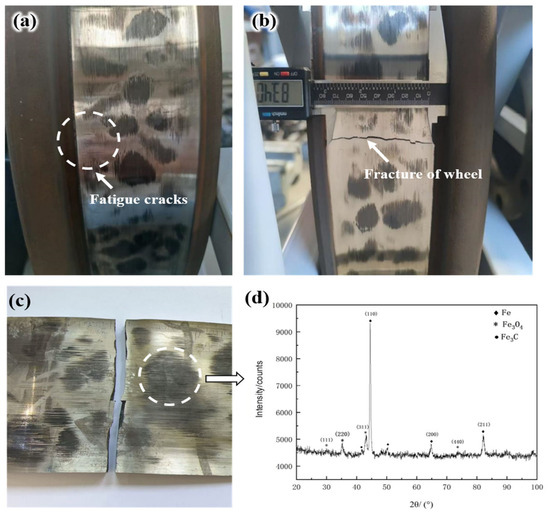
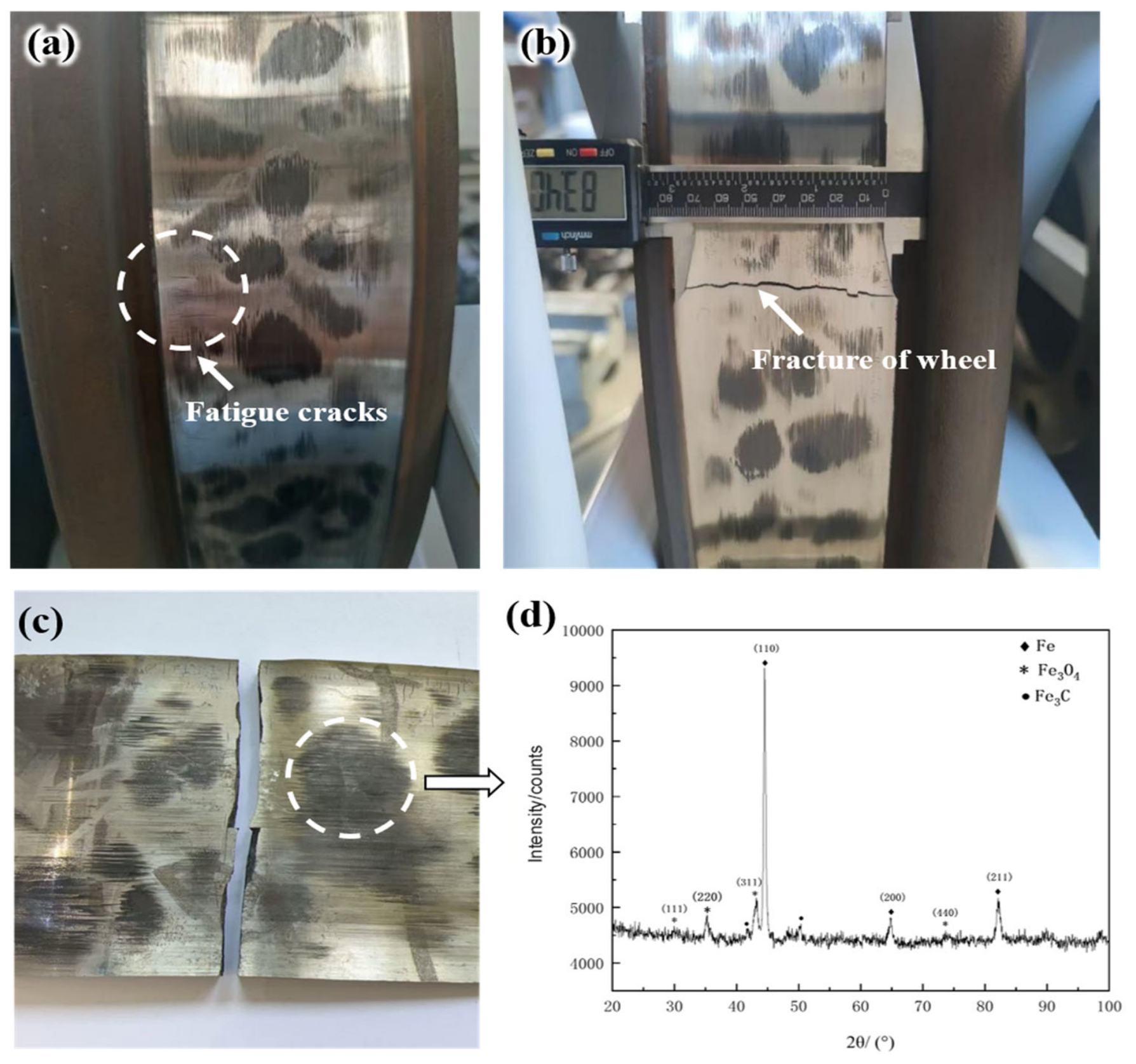
After braking wear, the obvious fatigue damage is found at the wheel sample surface, as shown in Figure 3. A large number of cracks is generated at the wheel tread after 500 cycles, and the dark areas are found at the wheel tread, as exhibited in Figure 3a. As the cycle is increased, the surface fatigue damage of the sample is serious. As the cycle reached to 1572 cycles, the fatigue fracture damage occurred at the wheel tread (Figure 3b,c). The XRD is used to analyze the phase composition in dark areas of the wheel tread. In dark areas, the Fe3O4 compound is generated at the wheel tread (Figure 3d).
Figure 3.
The surface worn morphology of the wheel sample: (a) worn morphology at 500 cycles; (b,c) the worn morphology at 1572 cycles; (d) the XRD profile in dark area in Figure 3c.
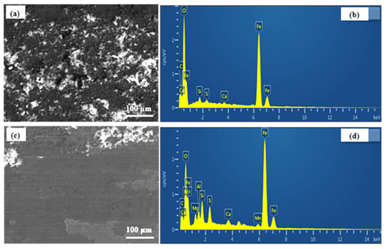
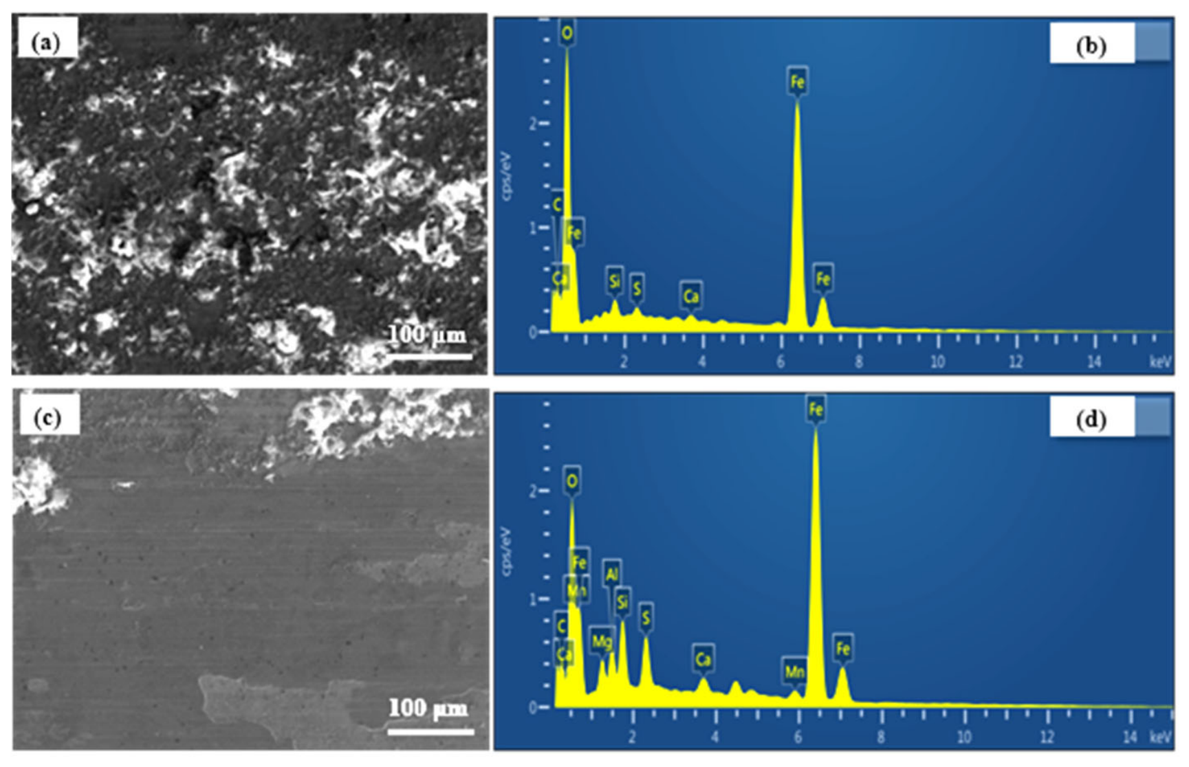
Figure 4 exhibits the worn morphology of the sample after 1572 cycles. In the black area, the worn surface of the sample (Figure 4a) is severely damaged and exhibits high surface roughness. The EDS map (Figure 4b) indicates that there are peaks of Fe and O elements at worn surface, confirming that the main component is an iron oxide (such as Fe2O3 or Fe3O4) and indicating that the dominant wear mechanism in this area is severe oxidative wear. In contrast, in the non-black area, the worn surface of the sample (Figure 4c) has only a small amount of wear product accumulation in the edge area, and the worn surface remains smooth, only showing minor polishing scratches; the EDS map (Figure 4d) shows that the intensity of the oxygen element’s peak is significantly decreased compared to sample in the dark area. It is indicated that no large amount of oxide is generated at the surface.
Figure 4.
The SEM micrograph of surface worn morphology of the sample: (a,b) the dark area; (c,d) non-dark area.
3.2. Microstructural Evolution
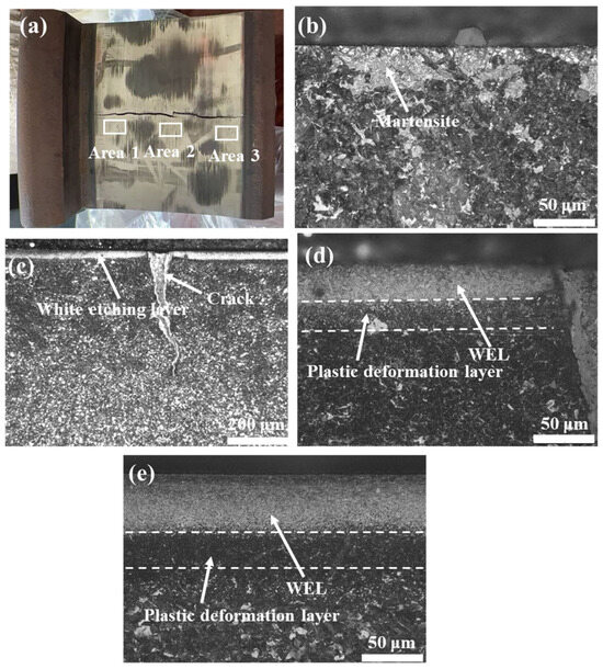
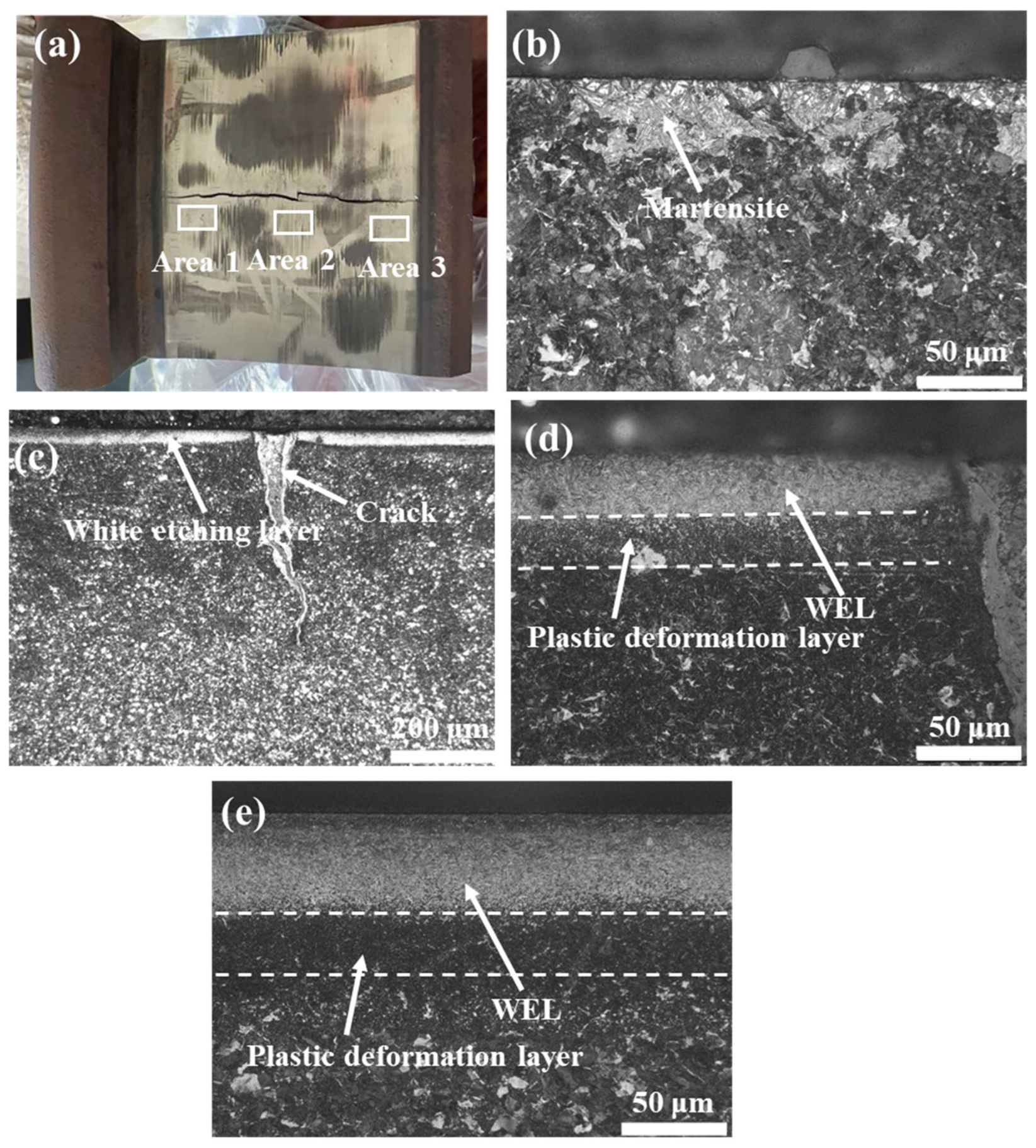
Figure 5 exhibits the surface morphology and cross-sectional OM micrographs of the wheel sample after wear failure. The obvious grooves are formed at the wheel surface, and the large crack is found (Figure 5a). The OM is conducted to observe the microstructural evolution of the wheel sample at different areas, as shown in Figure 5b–d. The microstructure of the wheel surface is different in different areas due to the different stress distributions. In area 1, no obvious plastic deformation layer is found and the localized thermal white etching layer (T-WEL) is formed (Figure 5b). In area 2, the continuous T-WEL is produced, and the fatigue crack is found in the T-WEL, as displayed in Figure 5c. The thickness of T-WEL is 40 ± 3.2 μm, and the severe plastic deformation layer is formed underneath the T-WEL (Figure 5d). In area 3, a thicker T-WEL is formed at the wheel surface; its depth is 50 ± 2.6 μm. The thickness of the severe plastic deformation layer underneath the T-WEL is 26 ± 3.5 μm (Figure 5e).
Figure 5.
The surface morphology and cross-sectional optical micrograph (OM) after wear: (a) surface macro-morphology; (b) area 1; (c,d) area 2; (e) area 3.
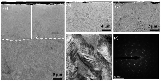
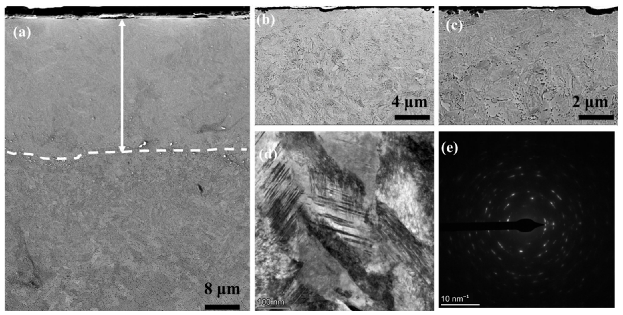
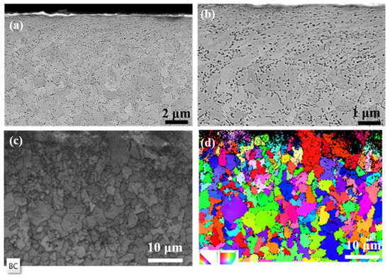
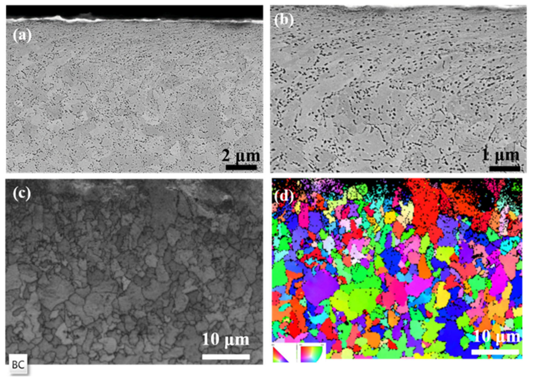
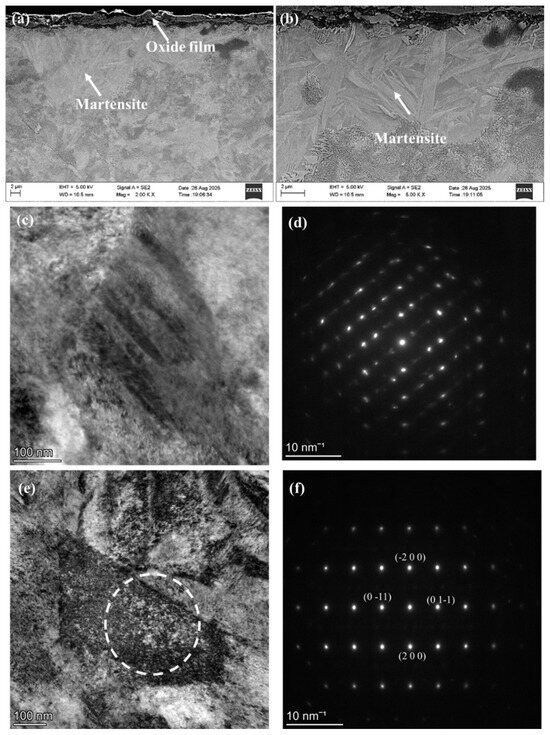
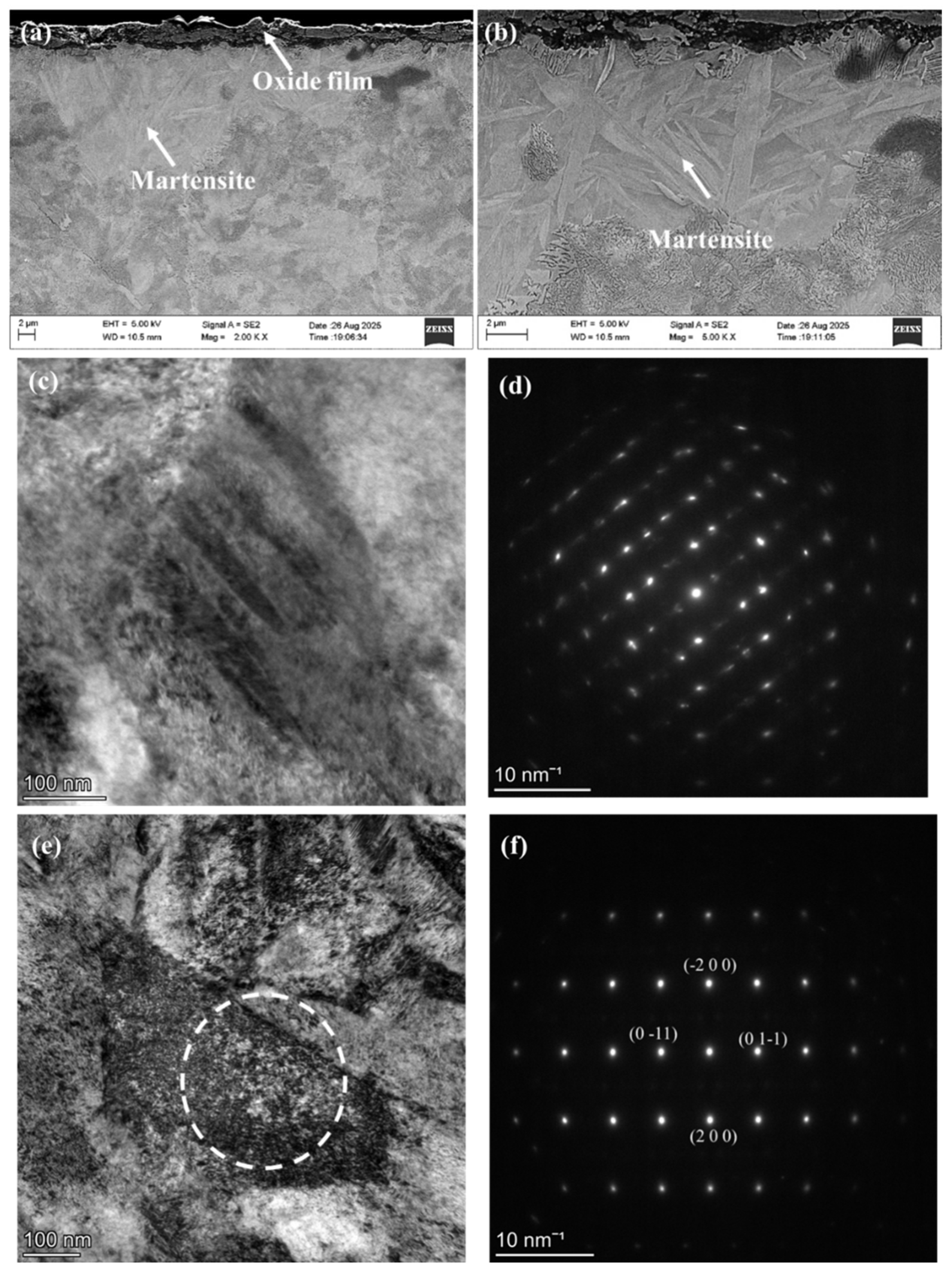
The SEM and TEM are used to characterize the microstructure of the continuous T-WEL, as shown in Figure 6. It can be seen in Figure 6a that a continuous T-WEL is formed, and the thickness of the T-WEL is about 40 μm. According to the observation of Figure 6b,c, the microstructure in the WEL is composed of the martensite phase. Researchers of Voortman Landström et al. [24] and Yang et al. [30] revealed that the temperature is about 500–650 °C at the interface between the wheel and brake shoe by using thermocouple and thermal finite element models, respectively. During the sliding wear process, the high dislocation density, refined grains and fragment of cementite are formed at the wheel surface, which can reduce the kinetic barrier of phase transformation [31,32,33]. As the severe plastic deformation is generated in the material, the temperature of the formation of austenite is reduced to about 550–650 °C [34,35]. As a result, the martensite phase is likely generated in the WEL after sliding wear, although no direct thermal measurements were performed during the full-scale braking test. After wear, the lath martensite is found in the T-WEL (Figure 6d,e). Figure 7 exhibits the surface microstructure of the wheel sample in the non-WEL region. The obvious plastic flow is produced at the surface after wear. The lamellar cementite fragments into the cementite particles in the plastic deformation layer. The ferrite grains are obviously refined in the plastic deformation layer (Figure 7c,d). Figure 8 exhibits the microstructural evolution of the sample underneath the dark area in Figure 3. The obvious oxide film is formed at the surface; its thickness is about 2 μm (Figure 8a). Underneath the oxide film, the local martensite phase is found, as shown in Figure 8b–d. Figure 8e,f exhibits the TEM micrograph in the non-T-WEL area. The ferrite grains are obviously refined, and high dislocation density is formed owing to severe plastic strain.
Figure 6.
The microstructural evolution in the continuous T-WEL: (a) low magnification of SEM; (b,c) the high magnification of SEM; (d) the TEM in T-WEL; (e) selected area electron diffraction in T-WEL.
Figure 7.
The SEM micrograph of the sample in plastic deformation layer: (a) low magnification; (b) high magnification; (c,d) EBSD micrographs.
Figure 8.
The SEM and TEM micrographs of the sample at oxide area: (a) low magnification SEM; (b) high magnification SEM; (c) TEM of martensite; (d) selected area electron diffraction of martensite; (e) TEM of ferrite; (f) selected area electron diffraction of ferrite.
3.3. Hardness Evolution
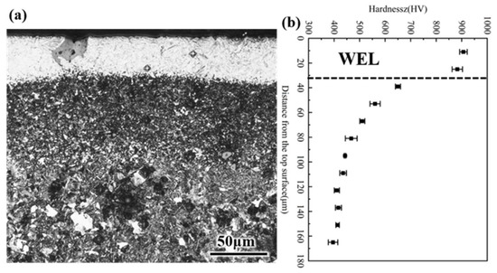
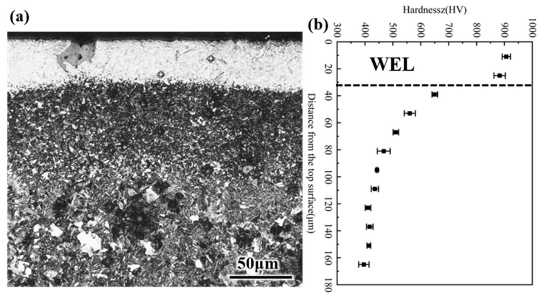
The variation in hardness of the sample in the WEL is measured, as shown in Figure 9. In the WEL, the sample’s hardness reached to about 900 HV due to the generation of the martensite phase and the refined grains. As the distance from the surface increases, the sample’s hardness is gradually reduced. In the plastic deformation layer, the refined ferrite grains and generation of a high density of dislocation contribute to enhancement of the sample’s hardness, whose value is about 700 HV. The thickness of the plastic deformation layer is about 40 μm. As the distance reached to about 100 μm, the sample’s hardness reached to the matrix; its hardness is about 400 HV.
Figure 9.
The variation in hardness at different distances from surface: (a) OM; (b) hardness evolution.
3.4. Fatigue Cracks
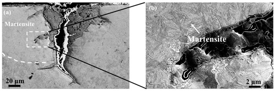
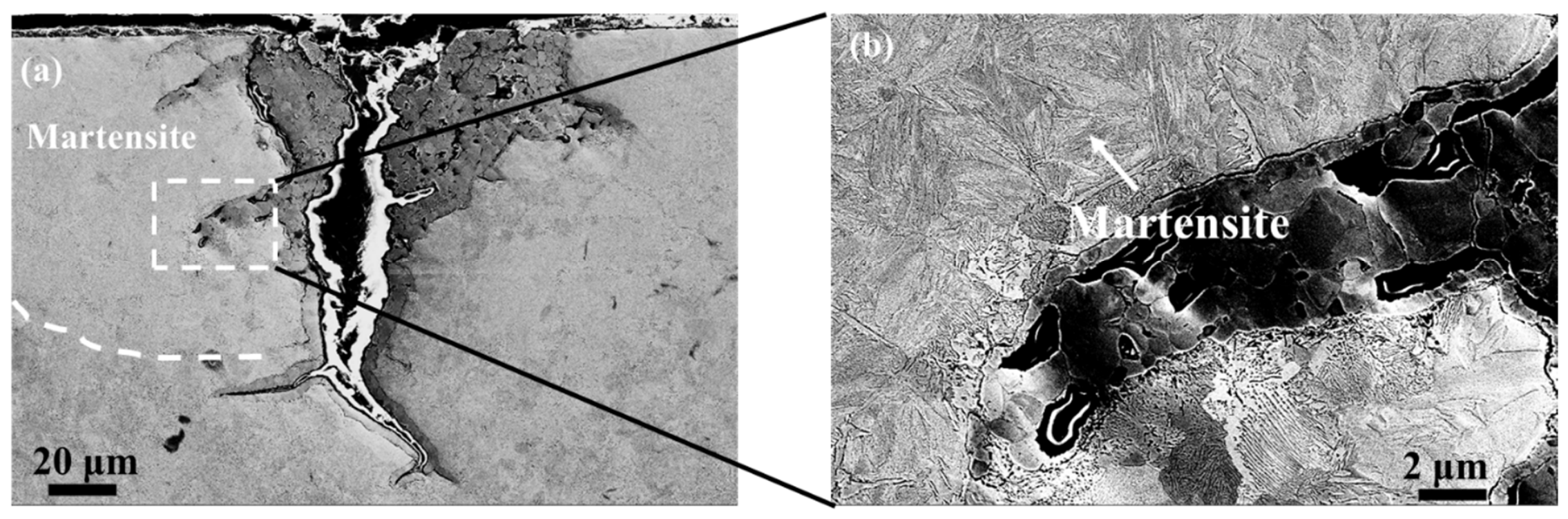
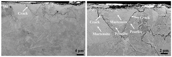
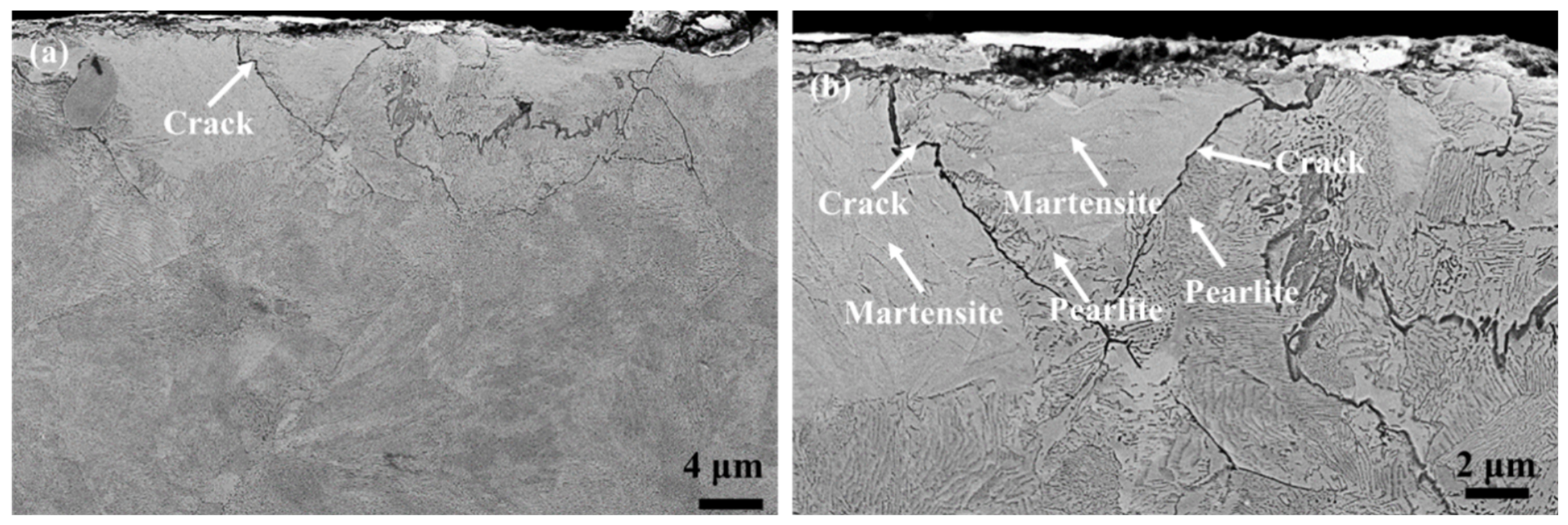
Figure 10 shows the fatigue crack of the sample in the continuous T-WEL after wear failure. The fatigue crack is initiated at the surface and propagates into the matrix, and the branch cracks are formed, as shown in Figure 10a. The microstructure at the edge of the crack is the martensite phase, as presented in Figure 10b. As a result, the formation of continuous T-WEL causes the initiation and propagation of cracks. Figure 11 presents the fatigue crack of the sample in the localized T-WEL. The fatigue crack also initiates at the surface and propagates into the matrix (Figure 11a). The fatigue crack propagates at the interface between the martensite phase and pearlite, as shown in Figure 11b.
Figure 10.
The fatigue crack of the sample in continuous T-WEL: (a) low magnification; (b) high magnification.
Figure 11.
The fatigue crack of the samples in localized T-WEL: (a) low magnification; (b) high magnification.
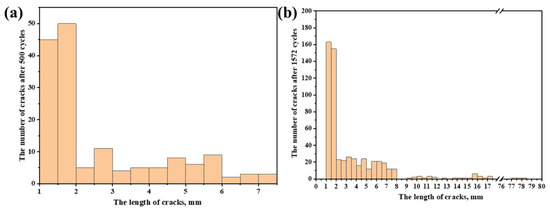
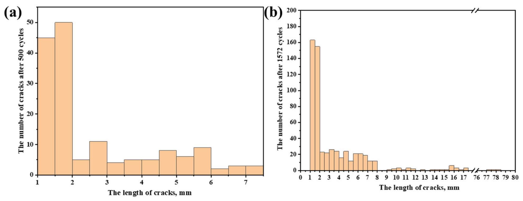
After 500 cycles, the crack lengths on the wheel tread were mainly distributed between 1 and 8 mm, with the highest number of cracks falling in the 1–2 mm range (Figure 12a), indicating that damage at this stage was still dominated by short surface cracks. The mean crack length of the wheel is 2.5 ± 0.5 mm at 500 cycles. Based on normalization according to the wheel tread circumference, the average linear crack density was approximately 0.06 cracks/mm. After 1572 cycles, both the number and size of cracks increased significantly, as shown in Figure 12b. When normalized by the wheel tread circumference, the average linear crack density increased to approximately 0.22 cracks/mm. The mean crack length of the wheel is increased to 5 ± 0.7 mm at 1572 cycles. Additionally, three long through-cracks, each about 70 mm in length, appeared on the specimen surface, which were considerably larger than other cracks. This phenomenon indicates that under long-cycle braking conditions, crack evolution has gradually transitioned from the initial stage of short crack initiation to a phase dominated by crack coalescence and rapid propagation. The tread cracks are typically associated with braking thermal loads, wheel–rail rolling contact stresses, and degradation of the surface material microstructure. Surface cracks may further propagate, connect, and lead to more severe tread damage under subsequent cyclic loading.
Figure 12.
The distribution of crack length of the sample: (a) 500 cycles; (b) 1572 cycles.
3.5. Fatigue Failure Mechanism
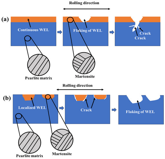
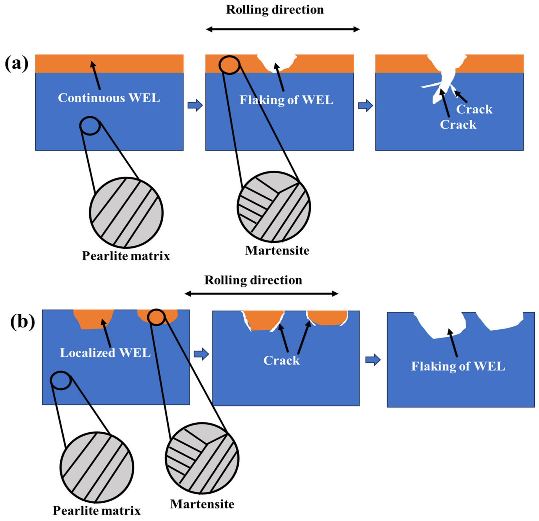
During the braking process of the wheel, the surface layer of the tread is prone to form T-WEL with high hardness and a martensite phase due to the combined effect of frictional heat input, high contact stress and rapid quenching [3,4]. The morphology of T-WEL presents continuous T-WEL and local T-WEL at the wheel tread due to nonuniform distribution of thermal-mechanical loads during braking at the wheel tread, as shown in Figure 5. The continuous T-WEL is formed in the normal braking condition, the brake shoe and the wheel tread are stably adhered, and the contact stress is uniformly distributed. During braking, the frictional heat continuously and uniformly enters the surface layer of the tread and the local temperature rapidly rises above the austenitization temperature of the wheel steel. At the same time, the uniform shear plastic deformation is formed. After the braking process, the sharp cooling can cause the martensite transformation at the wheel tread. As a result, the continuous T-WEL is formed at the wheel tread. The local T-WEL exhibits an arc-shaped and discontinuous patchy distribution feature, which results from the local thermal concentration at the wheel tread during the braking process [36]. The contact stress distribution between the braking shoe and the wheel is nonuniform. In some local areas, the high contact stress at the wheel tread can sharply increase friction heating, and then form a local high-temperature hot spot. The high-temperature hot spot dynamically sweeps along the arc of the tread, forming an arc-shaped heat-affected zone. After the braking process, the local high-temperature area is rapidly quenched, and eventually a local T-WEL is formed on the wheel tread, as shown in Figure 5.
Previous scholars found that the formation of T-WEL is the main factor to result in fatigue failure of the wheel [37,38]. The different shapes of T-WEL can change the fatigue crack paths. During the braking process, when the continuous T-WEL is formed at the wheel tread, the T-WEL exhibits high brittleness [39], which can be flaked. Then, the lager flaking pit is formed at the wheel tread, as shown in Figure 13a. The fatigue crack is initiated in the flaking pit and propagates into the matrix as the local T-WEL is formed due to the high temperature spot (Figure 5b and Figure 8a,b). The hardness difference between T-WEL and the pearlite is large [40]. During the braking process, the plastic deformation between T-WEL and pearlite is inharmonious. Therefore, the interface between the T-WEL and pearlite is the fatigue crack initiation paths. The fatigue cracks initiate and propagate at the interface between the T-WEL and pearlite (Figure 13b), which is similar to the result of Chen et al. [41]. As the fatigue crack propagates into the matrix, the large flaking is formed to accelerate the wheel fatigue failure.
Figure 13.
The schematic diagram of the mechanism of fatigue crack propagation: (a) continuous T-WEL; (b) localized T-WEL.
4. Conclusions
In our work, the relationship between the surface microstructure of the pearlite steel wheels and the formation of fatigue cracks during the braking process is investigated by using a full-size wheel braking test rig. After fatigue failure, the surface microstructural evolution and fatigue crack initiation and propagation paths of the wheel sample were systematically analyzed by OM, SEM and TEM, and the following conclusions were drawn:
(1) After braking of 1572 cycles, a large fatigue crack is formed on the wheel tread, which caused the wheel to break. After fatigue failure, some dark areas are formed on the wheel tread, which is composed of Fe3O4 compounds. This indicated that severe oxidation was produced on the wheel tread during braking due to high temperatures.
(2) After the wheel fatigue failure, a continuous T-WEL is formed in some areas of the wheel tread, while localized T-WEL is formed in other areas due to the nonuniform contact stress distribution. The microstructure of the T-WEL is composed of the martensite phase because the rapid increase and decrease in temperature on the wheel tread during the braking process causes martensitic transformation at the wheel tread.
(3) The hardness of the sample reached to about 900 HV. As the distance is increased, the sample hardness is reduced. In the plastic deformation layer, the sample’s hardness decreased to 700 HV. The thickness of the plastic deformation layer is about 40 μm.
(4) The propagation paths of fatigue cracks in the continuous T-WEL and localized T-WEL are different. In the continuous T-WEL area, the continuous T-WEL of the wheel can be peeled off during the braking wear process, and then the fatigue crack is gradually propagated into the matrix in the T-WEL peeled area. As for the localized T-WEL area, due to the large hardness difference between the T-WEL and pearlite, the fatigue crack is initiated at the interface between the T-WEL and pearlite and gradually propagates into the matrix.
Author Contributions
Conceptualization, M.F. and P.L.; Methodology, M.F. and Y.W.; Validation, M.F., G.Z., X.L., G.L., S.S., Y.W. and P.L.; Formal analysis, M.F., G.Z. and P.L.; Investigation, M.F., G.Z., X.L., G.L., S.S., Y.W. and P.L.; Resources, M.F. and P.L.; Data curation, G.L. and S.S.; Writing—original draft, M.F., Y.W. and P.L.; Writing—review and editing, Y.W. and P.L.; Visualization, X.L. and S.S.; Supervision, G.Z. and P.L. All authors have read and agreed to the published version of the manuscript.
Funding
This work was supported by the Advanced Materials-National Science and Technology Major Project of China (No. 2025ZD0610800), the China National Railway Group Science and Technology Program (No. Q2024J013) and the Research Project of China Academy of Railway Sciences Corporation Limited (No. 2025YJ004).
Data Availability Statement
The original contributions presented in this study are included in the article. Further inquiries can be directed to the corresponding authors.
Conflicts of Interest
Authors Mingzhe Fan, Guanzhen Zhang, Xiang Li, Guang Li and Yi Wu were employed by the company Metals and Chemistry Research Institute, China Academy of Railway Sciences Corporation Limited. The funding sponsors had no role in the design of the study; in the collection, analyses, or interpretation of data; in the writing of the manuscript; or in the decision to publish the results. The remaining authors declare no conflicts of interest.
References
- Freisinger, M.; Fellner, S.; Gammer, C.; Riedl, H.; Hahn, R. Stratified surface layers affecting crack propagation in wheel-rail contacts. Tribol. Int. 2024, 192, 109319. [Google Scholar] [CrossRef] [Scilit]
- Günay, M.; Korkmaz, M.E.; Ozmen, R. An investigation on braking systems used in railway vehicles. Eng. Sci. Technol. Int. J. 2020, 23, 421–431. [Google Scholar] [CrossRef] [Scilit]
- Vernersson, T.; Lundén, R. Temperatures at railway tread braking. Part 3: Wheel and block temperatures and the influence of rail chill. IMechE J. Rail Rapid Transit. 2007, 221, 443–454. [Google Scholar] [CrossRef] [Scilit]
- Teimourimanesh, S.; Lundén, R.; Vernersson, T. Braking capacity of railway wheels– state -of-the-art survey. In Proceedings of the 16th International Wheelset Congress, Cape Town, South Africa, 14–19 March 2010; p. 18. [Google Scholar]
- Nikas, D.; Ahlström, J.; Malakizadi, A. Mechanical properties and fatigue behaviour of railway wheel steels as influenced by mechanical and thermal loadings. Wear 2016, 366, 407–415. [Google Scholar] [CrossRef] [Scilit]
- Cvetkovski, K.; Ahlström, J.; Karlsson, B. Thermal degradation of pearlitic steels: Influence on mechanical properties including fatigue behaviour. Mater. Sci. Tech. 2011, 27, 648–654. [Google Scholar] [CrossRef] [Scilit]
- Ahlström, J.; Karlsson, B. Microstructural evaluation and interpretation of the mechanically and thermally affected zone under railway wheel flats. Wear 1999, 232, 1–14. [Google Scholar] [CrossRef] [Scilit]
- Bosso, N.; Cantone, L.; Falcitelli, G.; Gjini, R.; Magelli, M.; Nigro, F.M.; Ossola, E.; Zampieri, N. Simulation of the thermo-mechanical behaviour of tread braked railway wheels by means of a 2D finite element model. Tribol. Int. 2023, 178, 108074. [Google Scholar] [CrossRef] [Scilit]
- Kwon, S.J.; Seo, J.W.; Jun, H.K.; Lee, D.H. Damage evaluation regarding to contact zones of high-speed train wheel subjected to thermal fatigue. Eng. Fail. Anal. 2015, 55, 327–342. [Google Scholar] [CrossRef] [Scilit]
- Ghidini, L.; Zanardi, F.; Mazzù, A.; Faccoli, M. Innovative small-scale testing to investigate thermo-mechanical damage in tread-braked railway wheel steel paired with various types of cast iron. Wear 2025, 574, 206102. [Google Scholar] [CrossRef] [Scilit]
- Ghidini, L.; Mazzù, A.; Faccoli, M. Experimental study of wear and rolling contact fatigue in railway wheel steels coupled with various brake block materials: Insights from innovative small-scale testing. Wear 2024, 558, 205558. [Google Scholar] [CrossRef] [Scilit]
- Shen, J.H.; Pan, Y.; Zuo, J.Y. Study on thermal fatigue damage mechanisms for high-speed train’s wheel-mounted brake disc considering multiaxial stress state. Eng. Fail. Anal. 2025, 174, 109525. [Google Scholar] [CrossRef] [Scilit]
- Wu, W.T.; Zheng, M.S.; Lu, K.J.; Liu, F.; Song, Y.H.; Liu, M.C.; Dang, Z.M. Thermally conductive composites based on hexagonal boron nitride nanosheets for thermal management: Fundamentals to applications. Compos. Part A Appl. Sci. Manuf. 2023, 169, 107533. [Google Scholar] [CrossRef] [Scilit]
- Ishizaka, K.; Lewis, S.R.; Lewis, R. The low adhesion problem due to leaf contamination in the wheel/rail contact: Bonding and low adhesion mechanisms. Wear 2017, 378–379, 183–197. [Google Scholar] [CrossRef] [Scilit]
- Zhu, Y.; Olofsson, U.; Nilsson, R. A field test study of leaf contamination on railhead surfaces. Proc. Inst. Mech. Eng. Part F J. Rail Rapid Transit 2014, 228, 71–84. [Google Scholar] [CrossRef] [Scilit]
- Wang, W.J.; Wang, F.; Gu, K.K.; Ding, H.H.; Wang, H.Y.; Guo, J.; Liu, Q.Y.; Zhu, M.H. Investigation on braking tribological properties of metro brake shoe materials. Wear 2015, 330, 498–506. [Google Scholar] [CrossRef] [Scilit]
- Luo, Y.; Tao, G.; Su, J.; Wen, Z.; Wang, W.; Liu, K. Frictional temperature prediction of freight wagon wheel-brake shoe during non-steady tread braking on long and steep slope considering real-time temperature monitoring. Appl. Therm. Eng. 2026, 288, 129638. [Google Scholar] [CrossRef] [Scilit]
- Angella, G.; Ghidini, L.; Faccoli, M. AnAlternative Method of Investigating the Thermal Stability of Shoe-Braked Railway Wheel Steels Based on Strain Hardening Analysis. Metals 2024, 14, 814. [Google Scholar] [CrossRef] [Scilit]
- Zhang, R.X.; Su, L.L.; Zhao, C.; Fu, R.; Yun, X.B. Experimental study on the relationship between freight train wheel brake temperature and slope gradient. Therm. Sci. Eng. Prog. 2026, 73, 104644. [Google Scholar] [CrossRef] [Scilit]
- Su, J.B.; Ding, H.H.; Wang, W.J.; Huang, X.Q.; Zhang, S.Y.; Lewis, R.; Meli, E.; Liu, Q.Y.; Zhou, Z.R. Experimental study on the effect of brake shoe pressure on wheel wear and fatigue damage behavior during tread braking. Wear 2025, 571, 205840. [Google Scholar] [CrossRef] [Scilit]
- Caprioli, S.; Vernersson, T.; Handa, K.; Ikeuchi, K. Thermal cracking of railway wheels: Towards experimental validation. Tribol. Int. 2016, 94, 409–420. [Google Scholar] [CrossRef] [Scilit]
- Tian, Y.; Tan, Z.L.; Li, H.J.; Wang, R.; Shan, A.L.; Zhang, M.; Zhu, H.T. Tread evolution of bainitic heavy-haul freight wheels due to progressive heat accumulations from cyclic drag braking. Eng. Fail. Anal. 2025, 171, 109344. [Google Scholar] [CrossRef] [Scilit]
- Wang, B.; Wu, Q.; Luo, S.H.; Spiryagin, M.; Ma, W.H.; Ding, H.H.; Yang, Z.L. Wheel tread temperature assessment and its impact on rolling contact fatigue under long-term braking conditions. Tribol. Int. 2024, 200, 110162. [Google Scholar] [CrossRef] [Scilit]
- Landström, E.V.; Vernersson, T.; Lundén, R. Analysis and testing of tread braked railway wheel-Effects of hot spots on wheel performance. Int. J. Fatigue 2024, 180, 108116. [Google Scholar] [CrossRef] [Scilit]
- Su, J.B.; Huang, X.Q.; Ding, H.H.; Meli, E.; Wang, W.J.; Zhang, S.Y. On the transition behavior between rolling contact fatigue and thermal fatigue of freight wheels under various contact parameters/modes during tread braking process. Int. J. Fatigue 2026, 209, 109650. [Google Scholar] [CrossRef] [Scilit]
- Faccoli, M.; Zani, N.; Ghidini, A.; Petrogalli, C. Tribological behavior of two high performance railway wheel steels paired with a brake block cast iron. Tribol. Trans. 2021, 65, 296–307. [Google Scholar] [CrossRef] [Scilit]
- Faccoli, M.; Zani, N.; Ghidini, A.; Petrogalli, C. Experimental and numerical investigation on the wear behavior of high performance railway wheel steels paired with various brake block materials under dry sliding conditions. Wear 2022, 506, 204456. [Google Scholar] [CrossRef] [Scilit]
- Faccoli, M.; Provezza, L.; Petrogalli, C.; Ghidini, A.; Mazzù, A. A small-scale experimental study of the damage due to intermittent shoe braking on the tread of high-speed train wheels. Tribol. Trans. 2020, 63, 1041–1050. [Google Scholar] [CrossRef] [Scilit]
- Mazzù, A.; Provezza, L.; Zani, N.; Petrogalli, C.; Ghidini, A.; Faccoli, M. Effect of shoe braking on wear and fatigue damage of various railway wheel steels for high speed applications. Wear 2019, 434, 203005. [Google Scholar] [CrossRef] [Scilit]
- Yang, Y.F.; Tian, Q.Y.; Colao, C.; Chen, S.Q.; Wang, K.Y.; Hecht, M. Modelling framework for wheel-rail contact temperature evolution during braking. Int. J. Mech. Sci. 2026, 314, 111345. [Google Scholar] [CrossRef] [Scilit]
- Bandi, B.; Krevel, J.; Srirangam, P. Interaction between ferrite recrystallization and austenite formation in dual-phase steel manufacture. Metall. Mater. Trans. A 2022, 53, 1379–1393. [Google Scholar] [CrossRef] [Scilit]
- Tung, P.Y.; Zhou, X.; Morsdorf, L.; Herbig, M. Formation mechanism of brown etching layers in pearlitic rail steel. Materialia 2022, 26, 101625. [Google Scholar] [CrossRef] [Scilit]
- Carroll, R.I.; Beynon, J.H. Rolling contact fatigue of white etching layer: Part 2. Numerical results. Wear 2007, 262, 1267–1273. [Google Scholar] [CrossRef] [Scilit]
- Ramesh, A.; Melkote, S.N. Modeling of white layer formation under thermally dominant conditions in orthogonal machining of hardened AISI 52100 steel. Int. J. Mach. Tools Manuf. 2008, 48, 402–414. [Google Scholar] [CrossRef] [Scilit]
- Manco, G.L.; Caruso, S.; Rotella, G. FE modeling of microstructural changes in hard turning of AISI 52100 steel. Int. J. Mater. Form. 2010, 3, 447–450. [Google Scholar] [CrossRef] [Scilit]
- Zhu, Q.; Xie, J.; Cui, X.; Li, J. Study on wheel polygonal wear of high-speed train caused by the unstable vibration of the disc brake system. Wear 2025, 570, 205925. [Google Scholar] [CrossRef] [Scilit]
- Lewis, R.; Olofsson, U. Wheel–Rail Interface Handbook; Woodhead Publishing: Cambridge, UK, 2009. [Google Scholar]
- Handa, K.; Kimura, Y.; Mishima, Y. Surface cracks initiation on carbon steel railway wheels under concurrent load of continuous rolling contact and cyclic frictional heat. Wear 2010, 268, 50–58. [Google Scholar] [CrossRef] [Scilit]
- Freisinger, M.; Rojacz, H.; Pichelbauer, K.; Trausmuth, A.; Trummer, G.; Six, K.; Mayrhofer, P.H. Comparative study on the influence of initial deformation and temperature of thermally induced white etching layers on rail wheels. Tribol. Int. 2023, 177, 107990. [Google Scholar] [CrossRef] [Scilit]
- Liu, C.P.; Zhang, G.Z.; Chen, C.H.; Liu, P.T.; Pan, J.Z.; Zhang, B.; Ren, R.M. Formation mechanism for the white etching microstructure in the subsurface of the failure pearlite wheel steel. Wear 2022, 494, 204243. [Google Scholar] [CrossRef] [Scilit]
- Chen, Y.D.; Zhao, X.J.; Liu, P.T.; Pan, R.; Ren, R.M. Influences of local laser quenching on wear performance of D1 wheel steel. Wear 2018, 414, 243–250. [Google Scholar] [CrossRef] [Scilit]

Disclaimer/Publisher’s Note: The statements, opinions and data contained in all publications are solely those of the individual author(s) and contributor(s) and not of MDPI and/or the editor(s). MDPI and/or the editor(s) disclaim responsibility for any injury to people or property resulting from any ideas, methods, instructions or products referred to in the content. |
© 2026 by the authors. Licensee MDPI, Basel, Switzerland. This article is an open access article distributed under the terms and conditions of the Creative Commons Attribution (CC BY) license.