


Abstract
A transverse fracture occurred in U75V pearlitic rail after 5 months of service on a sharp radius curved track of mixed passenger-freight railway. Systematic tests including chemical composition analysis, mechanical properties testing, macroscopic fracture inspection, metallographic observation and microscopic morphology characterization were conducted on the failed rail sample. The results indicate that the rail base metal has qualified metallurgical quality. Its chemical composition, fundamental mechanical properties and microstructure fully meet the requirements of Chinese railway standard TB/T 2344.1-2020. The failure mode is identified as instantaneous brittle fracture. Severe mechanical extrusion and impact cause prominent plastic deformation on the rail foot, leading to surface plastic flow and further triggering micro-crack initiation. Under continuous cyclic stress induced by train loads, the micro-crack tips undergo repeated tearing and closing. Severe stress concentration accelerates the formation of transgranular cracks, which propagate rapidly and unstably toward the rail interior, eventually resulting in catastrophic transverse fracture. Standardized procedures in rail transportation, hoisting and laying are essential to avoid mechanical damage, while regular line inspection and timely replacement of damaged rails should be strictly enforced.
1. Introduction
In recent years, with the rapid development of railway construction toward heavy haul and high speed operation, train running speed, axle load and traffic density have been continuously increasing [1,2]. Consequently, rail damage has become increasingly severe. As a critical load-bearing component of railway infrastructure, rail quality plays a vital role in operational safety. Sharp radius curved tracks are typical accident-prone segments and widely adopted in urban rail transit, mountain railways and connecting railway lines. On such curved trackss, wheel-rail contact evolves from surface contact to point contact. When trains pass through, the stress level between wheels and rails is considerably higher than that on straight tracks, leading to more severe rail damage [3].
With its excellent comprehensive mechanical properties, wear resistance and cost advantages, pearlitic rail has become the mainstream rail material of ordinary speed railway, heavy haul railway and urban rail transit at home and abroad [4,5,6,7]. The service environment of rail in railway lines is complex and diverse, the main failure modes of rail can be divided into three categories: wear, rolling contact fatigue and fracture caused by external factors [8,9,10,11,12]. At present, domestic and foreign studies concerning rail damage analysis and engineering applications are predominantly concentrated on typical failure modes including wear and rolling contact fatigue. Most researchers adopt laboratory twin-disc rolling friction and wear tests to investigate the wear resistance of rail materials as well as the propagation law of rolling contact fatigue cracks [13,14,15,16,17,18,19,20]. In actual service, the initiation and propagation cycles of rail wear and rolling contact fatigue damage are generally relatively long with distinct damage characteristics. Such defects can be effectively monitored and prevented during routine railway inspection and maintenance. Severely damaged rails can be replaced in time before fracture occurs, thus ensuring the safe operation of railway.
The rail laid on the track breaks under the action of wheel-rail alternating stress due to its internal and external defects and the influence of comprehensive factors such as the use environment, fracture is one of the most dangerous forms of rail failure, which may cause major safety accidents [21,22,23]. Many researchers have conducted a lot of research on various failure mechanisms and causes of rail. Current researches on rail fracture failure can be mainly divided into two categories. The first category focuses on laboratory experiments and finite element simulations concerning the initiation mechanism of fatigue cracks, crack propagation paths and fracture behaviors of rails. Leonetti et al. [24] experimentally characterized the fatigue crack growth rate and fracture toughness of heat-treated R350HT pearlitic rail, and analyzed the fatigue fracture mechanisms, they concluded that refined pearlite lamellar structures can hinder crack propagation and delay rail fracture. Sjoerd et al. [25] investigated the mixed-mode fracture toughness of R260Mn rails and clarified the dominant stress intensity factor corresponding to mixed-mode fracture failure. Seo et al. [26] evaluated the fatigue properties and fracture behaviors of rails applied in Korean railway lines. A series of uniaxial tensile tests, fracture toughness tests and fatigue crack growth tests were carried out at room and low temperatures, and the temperature-dependent fatigue fracture characteristics of rails were discussed accordingly. Jun et al. [27] performed failure analysis on fractured weld-repaired rails combined with finite element simulation, and obtained the residual stress distribution under different service conditions. The results indicated that weld defects and rapid microstructural transformation especially at the bonding interface are the main inducements for crack initiation. In addition, the existence of high tensile residual stress can markedly accelerate the crack propagation rate. However, laboratory test conditions are difficult to fully replicate the complex in-service service environment of field railway lines. In actual engineering applications, rails undergo multiple processes including transportation, handling, installation and long-term field operation, and are inevitably affected by various external interference factors. These adverse effects tend to induce various mechanical defects, and further increase the risk of in-service fracture failure of rails.
The other research direction concentrates on failure analysis based on practical engineering cases of damaged rails. Al-Juboori et al. [28] analyzed a typical rail fracture failure case. White etching layers and rolling contact fatigue were observed on the rail surface, where indentation defects were initiated. Subsequently, cracks propagated inward into martensitic islands inside the rail head at a shallow angle, which accelerated crack growth and eventually induced transverse fracture. The formation of such martensitic islands was attributed to inappropriate heat treatment during rail manufacturing. Godefroid et al. [29] investigated the fracture failure of flash-butt welded rail joint. The results revealed that unreasonable finish machining parameters on weld surfaces caused severe stress concentration, accompanied by abnormal microstructures within the weld zone. Fatigue cracks initiated on the weld surface and propagated in a brittle manner, finally resulting in the fracture of welded joint. Nguyen et al. [30] adopted the laboratory three-point bending test to explore the effects of white etching layers (WELs) on crack propagation and fracture characteristics of rails. It was confirmed that cracks were more likely to nucleate within WELs and tended to propagate in an intergranular fracture mode. By contrast, rails without WELs failed via quasi-cleavage transgranular fracture and possessed longer service life. Xu et al. [31] explored the fracture mechanism of flash-butt welded joints of fractured U75V rails. The failure was identified as fatigue fracture. Improper grinding treatment introduced martensitic microstructures on the lower surface of the rail base. After on-track service, cracks initiated and propagated within these martensitic regions under tensile stress, leading to transverse fracture of welded joints. Chen et al. [32] conducted detection and analysis on fractured specimens generated during rail straightening. During the straightening process, mechanical friction between straightening rollers and rail heads contributed to the formation of martensitic bright layers, cracks initiated in these martensitic structures and expanded rapidly under straightening force, giving rise to brittle rail fracture. Wang et al. [33] clarified the causes of transverse fracture of U75V rails during sawing operation. The cracks originated from the triangular zone of the rail web. Unreasonable supporting methods during sawing led to instantaneous rail cracking under gravitational load when cutting approached the critical position. In summary, existing reported rail fracture cases are mainly induced by improper manufacturing techniques, abnormal weld microstructures, inadequate surface grinding and surface martensite formation. This study focuses on a failure case distinctly different from previously reported ones. The investigated rail serving on sharp radius curves suffered rapid brittle fracture within an extremely short service period due to mechanical damage on the rail base, which poses severe threats to train operation safety. Similar failure cases under such service conditions are rarely reported. Therefore, it is of great necessity to systematically clarify its failure causes and intrinsic fracture mechanisms.
In this study, a fractured pearlitic rail from a mixed passenger-freight railway line with a sharp radius curve was selected as the research object. To identify the root cause of rail fracture, specimens were extracted from the failed rail, and comprehensive tests and analyses were carried out, including chemical composition testing, mechanical properties measurement, macroscopic fracture observation, metallographic characterization and microscopic morphology analysis. The essential fracture mechanisms were discussed. This work aims to provide a scientific reference for the maintenance of pearlitic rails on curved tracks and ensure the safe and stable operation of railway.
2. Materials and Methods
2.1. Research Background
The research object of this study is a rail that experienced transverse fracture in a sharp radius curved track. The rail was of the 60 kg/m U75V pearlite type, which fractured transversely only 5 months after being laid. In the early stage of rail laying, commissioning and running-in operations were mainly carried out by engineering maintenance vehicles on the track. The line was officially opened to traffic 4 months after rail installation, and transverse fracture occurred in the fifth month. Despite its short service life, the rail suffered complete failure, making this case highly typical and of certain research value.
To clarify the service environment background of the rail fracture, the detailed operating conditions of the railway line are supplemented as follows: This railway line is a mixed passenger and freight line with an annual total passing weight of 60 million tons. The curved section where the fractured rail was located has a radius of curvature of 600 m, which is classified as a typical sharp radius curved track. The maximum allowable operating speed for trains on this curved track is 80 km/h, and the actual running speed of trains during daily operation is mainly maintained in the range of 60–80 km/h. The maximum allowable axle load of the line is 23 tons, with freight trains as the main traffic and a small number of passenger trains passing through occasionally.
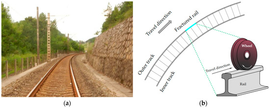
The on-site photograph of the railway line is shown in Figure 1a, which clearly displays that the curved track adopts a ballasted track with concrete sleepers. The schematic diagram of the fractured rail location is presented in Figure 1b, indicating that the fracture occurred on the outer track at the middle part of the curve.
Figure 1.
The photograph and schematic diagram of the sharp radius curved track: (a) on-site photograph of the curved track; (b) schematic diagram of the curved track.
2.2. Experimental Materials
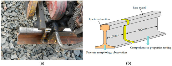
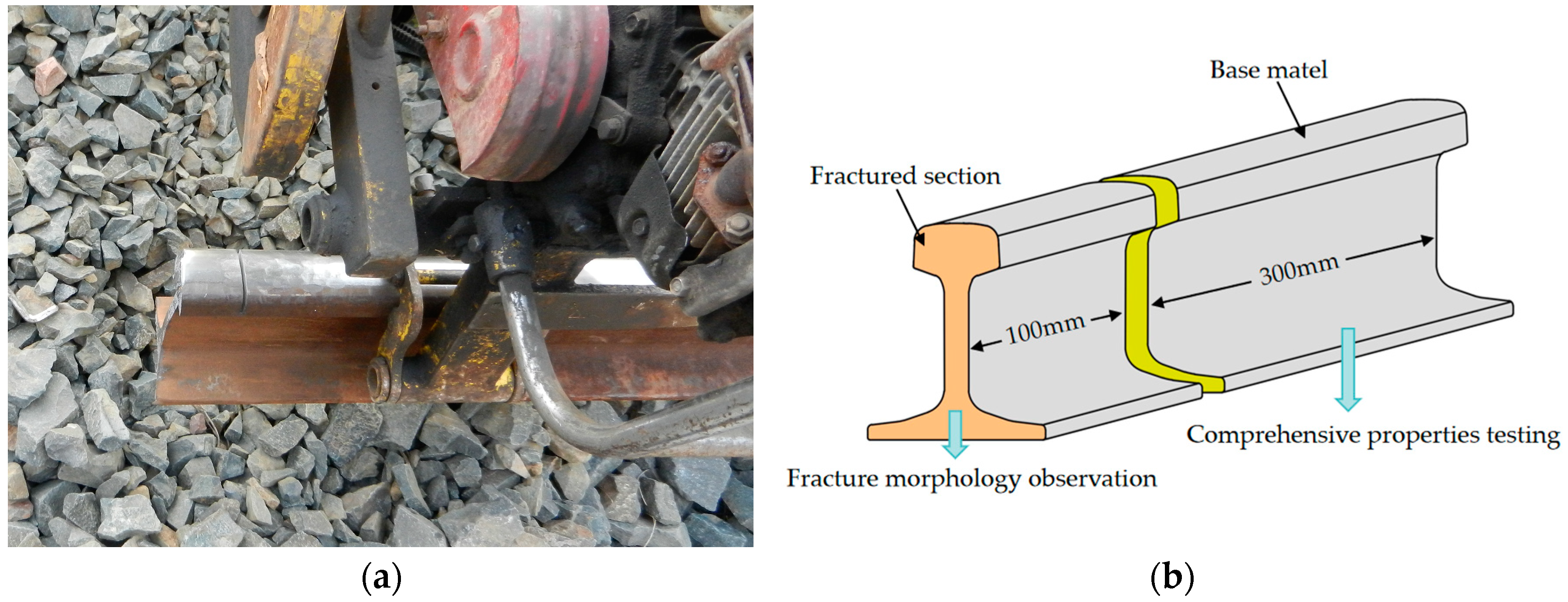
The experimental materials in this study were derived from transversely fractured rail. After the fractured rail was removed from service and replaced, the rail samples were taken from one end of the fractured rail, and the fractured rail was cut by sawing. The on-site sampling physical photograph is shown in Figure 2a.
Figure 2.
The photograph and schematic diagram of the fractured rail: (a) physical photograph; (b) sampling schematic diagram.
As shown in Figure 2b. Firstly, a sample segment containing the complete fracture surface was cut along the longitudinal direction of the rail, with a length of 100 mm. This sample is mainly used for macroscopic morphology observation, microscopic morphology characterization, and analysis of crack propagation direction characteristics. It can completely retain the original fracture morphology and crack propagation path, maximizing the restoration of real failure characteristics. After the cutting of the fracture sample was completed, a base metal sample with a length of 300 mm was further cut from the rail matrix adjacent to the fracture area. It is used for comprehensive performance testing of the rail base metal, including metallographic structure analysis, non-metallic inclusion rating, hardness testing and basic mechanical properties measurement.
2.3. Experimental Methods
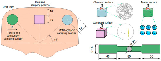
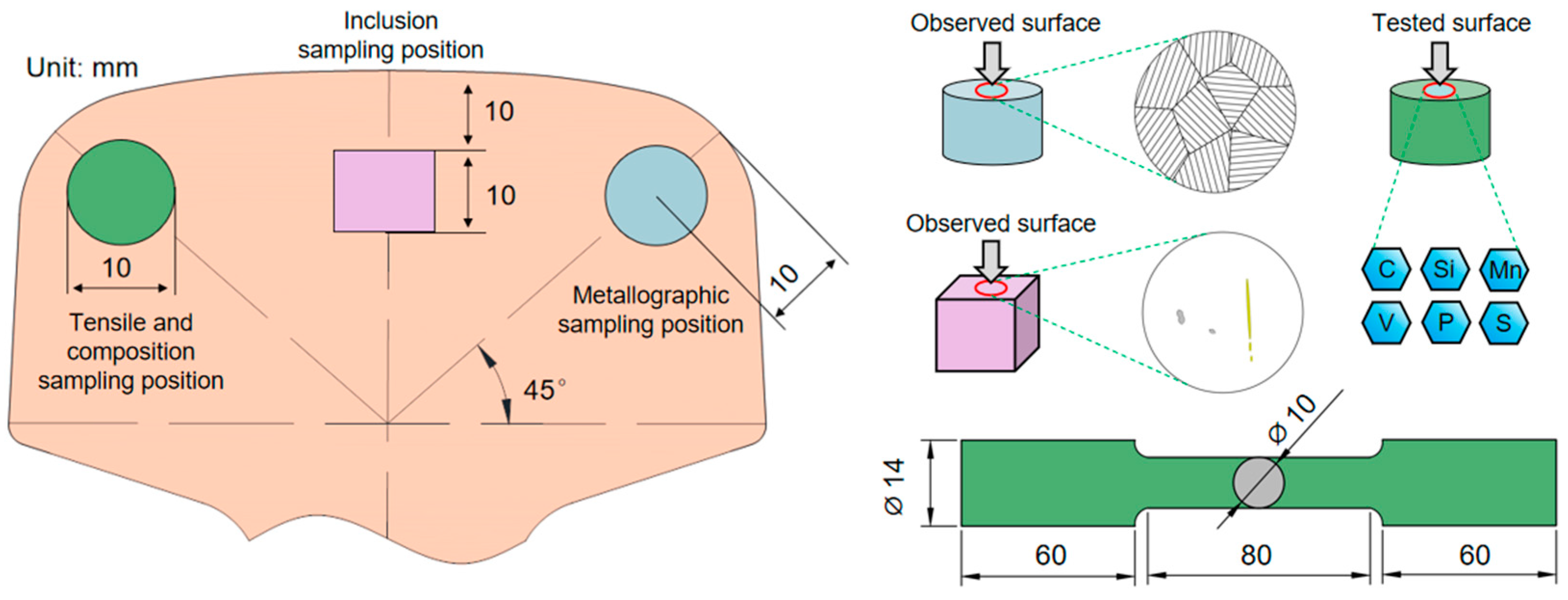
Rail fracture during service is generally attributed to unqualified internal and external quality of rails that fail to meet relevant technical standards. To clarify the basic mechanical properties, chemical composition, and microstructure of the fractured rail, systematic physical and chemical examinations were carried out in accordance with the technical requirements of the Chinese Railway Standard TB/T 2344.1-2020 [34], and the sampling positions for each test are presented in Figure 3.
Figure 3.
Sampling positions and dimensions of tested specimens.
The chemical composition of the rail base metal was determined using an ULTIMA-2C atomic emission spectrometer (HORIBA, Longjumeau, France), and the average value was calculated from three consecutive tests. The tensile strength and elongation after fracture of the base metal were measured with a Z600E tensile testing machine (ZwickRoell GmbH & Co., Ulm, Germany); each test was repeated twice, and the average value was adopted, with the specimen dimensions illustrated in Figure 3. The Brinell hardness of the rail head tread was measured using a BRIN-200D Brinell hardness tester (Foundrax, Somerton, UK). Prior to testing, the rail head tread was ground by 0.5 mm to remove surface defects and ensure a flat testing surface; each measurement was repeated five times, and the average value was taken. For metallographic analysis, the observation surface of the metallographic specimen was ground and polished sequentially, followed by etching with a 4 vol% nitric acid-alcohol solution. The microstructure and non-metallic inclusions of the base metal were observed using a LEICA DM6000M optical microscope (Leica Microsystems, Wetzlar, Germany).
The original fracture surface can completely retain the fracture morphology and crack propagation path, thereby restoring the real failure characteristics. Firstly, the fracture surface was ultrasonically cleaned with absolute ethanol to remove surface oil stains, dust, and other impurities. Subsequently, the fracture morphology and microstructure were observed using a LEICA DM6000M metallographic microscope and a FEI QUANTA 400 field emission scanning electron microscope (FE-SEM) (FEI, Hillsboro, OR, USA). EDS analysis was performed on the surface of the mechanically damaged fracture using the FEI QUANTA 400 FE-SEM to determine the main elemental composition. For further characterization of the finer microstructures, a JEM-2100F transmission electron microscope (TEM) (JEOL, Tokyo, Japan) was employed. The thin foils for TEM observation were mechanically ground to a thickness of approximately 40 µm, and then further thinned using a twin-jet electro-polisher with an electrolyte composed of 10 vol% perchloric acid and 90 vol% glacial acetic acid.
3. Results
3.1. Chemical Composition
The chemical composition test results of the rail base metal are shown in Table 1. It can be found that the chemical composition of the rail base metal is mainly C, Si, Mn and V elements, and a very small amount of P and S elements. Si and Mn elements mainly improve the mechanical properties of the rail base material by solid solution strengthening, V element mainly precipitates the second phase particles to strengthen the rail, P and S elements are regarded as harmful impurity elements in rail steel, whose mass fractions should be controlled at a low level as far as possible. From the mass fraction of each element in Table 1, the chemical composition of the base metal is within the range required by the Chinese railway standard TB/T 2344.1-2020.
Table 1.
Chemical composition of the rail base metal (wt%).
3.2. Tensile Properties and Tread Hardness
The tensile properties and tread hardness test results of the rail base metal are shown in Table 2. All measured indicators show stable distribution and fully comply with the technical requirements of Chinese railway standard TB/T 2344.1-2020. Sufficient tensile strength combined with desirable elongation effectively restrains plastic deformation failure induced by wheel-rail cyclic stress. Meanwhile, the relatively high tread hardness endows the rail with good wear resistance, which further guarantees its in-service structural stability.
Table 2.
Tensile properties and tread hardness of the rail base metal.
3.3. Metallographic Structure and Non-Metallic Inclusions
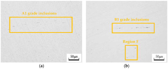
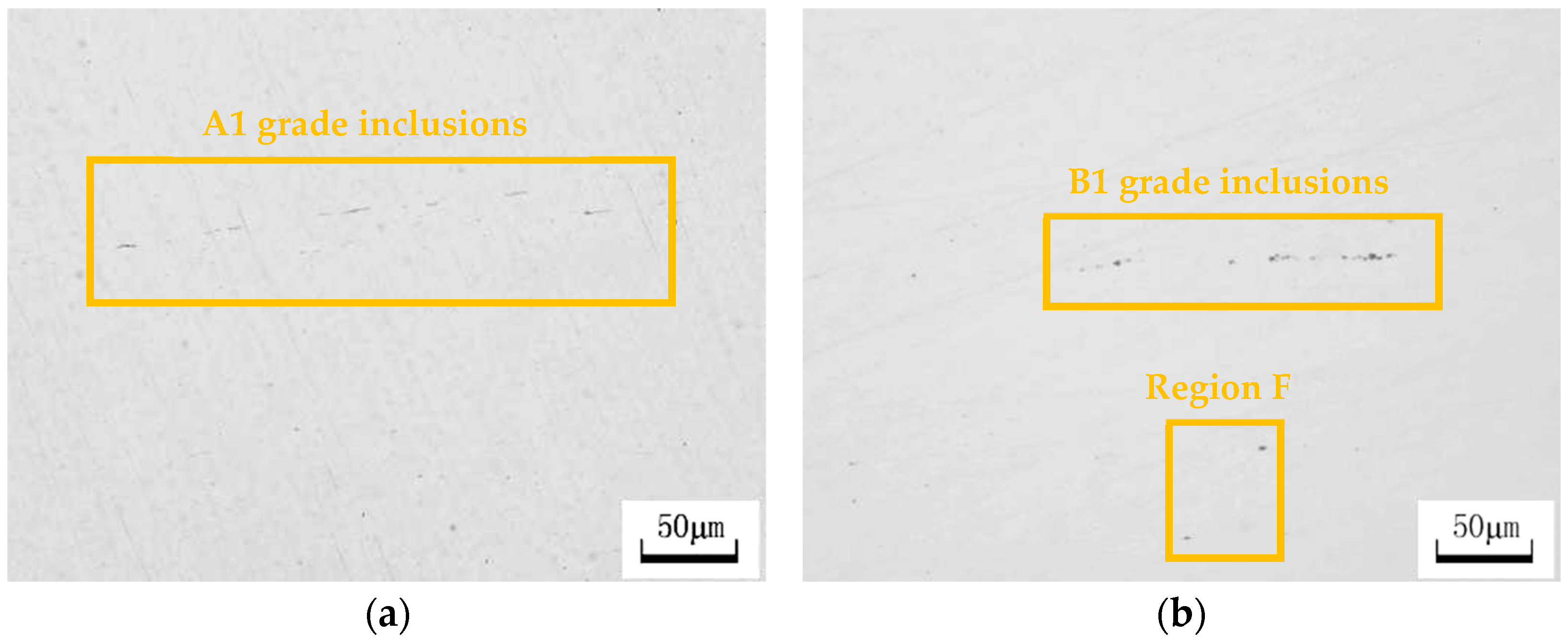
The non-metallic inclusions and metallographic structure of the rail base metal were characterized. The rating of both Class A and Class B non-metallic inclusions is Grade 1, while no Class C or Class D inclusions were detected. Typical micrographs of the inclusions are shown in Figure 4. In Figure 4a, slender and intermittently distributed Class A inclusions can be observed, with an effective total length of approximately 140 μm, corresponding to Class A1 grade. Figure 4b contains both Class A and Class B inclusions. The amount of Class A inclusions is relatively low, as shown in region F, with an effective total length of about 10 μm, which does not meet the grading requirement. Class B inclusions exhibit a dot-block morphology and distribute in a strip-like pattern, with an effective total length of around 110 μm, corresponding to Class B1 grade.
Figure 4.
Non-metallic inclusions of the rail base metal: (a) A1 grade; (b) B1 grade.
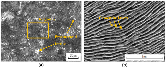
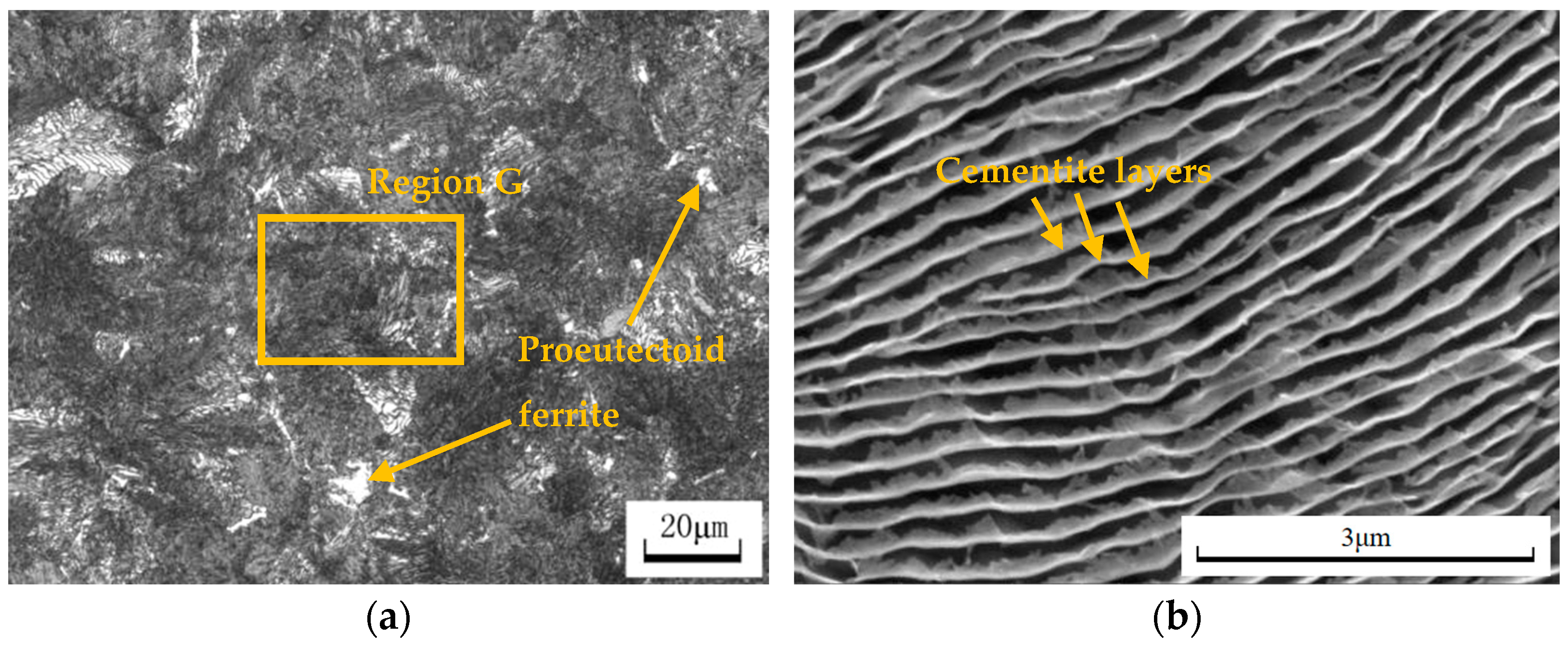
The metallographic structure of the rail consists of pearlite and a small amount of proeutectoid ferrite, and the proeutectoid ferrite is sporadically distributed at the grain boundaries, as shown in Figure 5a. The carbon content of the U75V rail is close to the eutectoid point (0.77 wt%), ensuring that its metallographic structure at room temperature is dominated almost entirely by pearlite. Figure 5b presents the SEM micrograph of the pearlite structure of region G. The pearlite shows intact lamellar morphology with clear boundaries, the cementite layers are uniformly distributed, and the average lamellar spacing is approximately 220 nm. All the above test results comply with the requirements specified in the Chinese railway standard TB/T 2344.1-2020.
Figure 5.
Metallographic photo and structure of the rail base metal: (a) metallographic photo; (b) pearlitic microstructure of region G.
3.4. Fracture Macroscopic Morphology
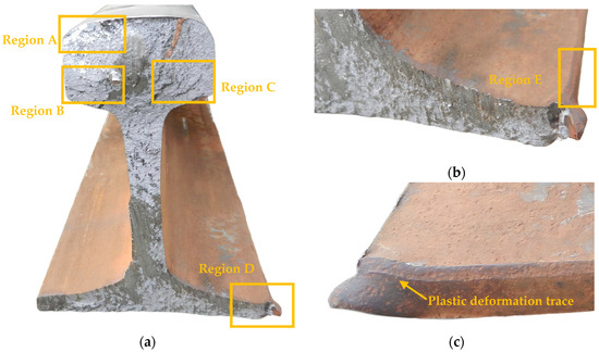
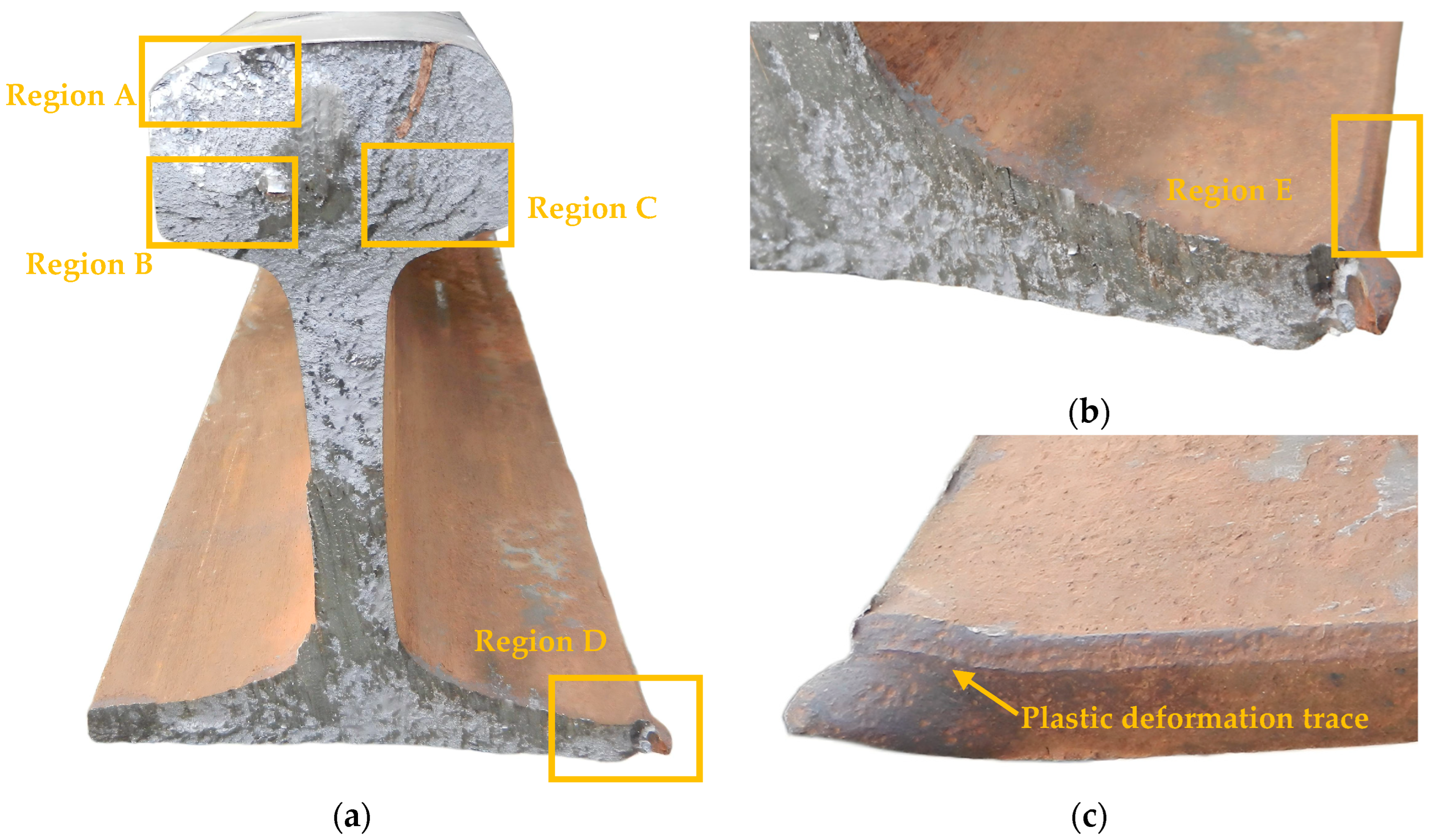
The macroscopic fracture morphology is shown in Figure 6a. It can be seen that obvious transverse fracture occurred on the rail. The crack penetrated vertically through the rail foot, rail web and rail head, resulting in complete separation of the rail on both sides of the fracture. Most areas of the fracture cross-section are grayish-white, which is caused by the rapid propagation of cracks through the metal. A small part of the cross-section exhibits a bright silvery metallic luster, this is because the fractured rail was not replaced in time, under the action of wheel load, the two fracture surfaces staggered up and down, resulting in mutual friction between the metals on the fracture surface. No obvious corrosion features on the overall fracture surface, indicating that the whole fracture process developed rapidly.
Figure 6.
The macroscopic morphology of the fractured rail: (a) transverse section morphology; (b) macroscopic morphology of region D; (c) macroscopic morphology of region E.
Several characteristic regions on the rail fracture surface deserve attention. Region A of the rail head presents a grayish-white fresh fracture, and no radial crack propagation direction was observed. Obvious metal extrusion traces appear near the surface. This may be attributed to the height difference on both sides after rail fracture; impact and extrusion were generated when the train wheels passed by. In region B and region C, distinct radial crack propagation paths can be observed, extending from the rail web toward the rail head. Compared with the rail head, the rail web and rail foot have less metal volume, lower structural strength and poorer resistance to crack instability. After the crack rapidly passed through the rail web and rail foot, it could not penetrate the rail head directly due to its large metal volume. Consequently, crack bifurcation and convergence occurred, forming radial cracks. The flat, smooth and grayish-white fracture characteristics of the rail web and rail foot also indirectly support this interpretation.
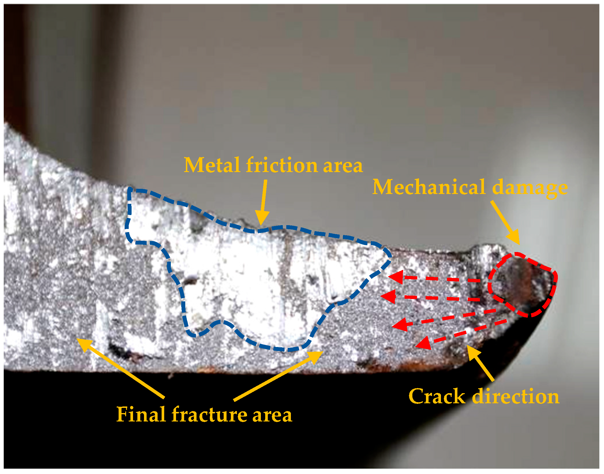
In region D of the rail foot, obvious mechanical damage can be observed near the outer side of the rail foot, as shown in Figure 6b. Further observation shows evident plastic deformation traces on the side of this mechanical damage, see Figure 6c.
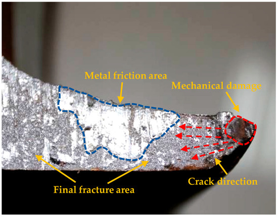
The enlarged morphology of region D is presented in Figure 7. The fracture of the mechanically damaged area is dark brown with obvious corrosion traces, indicating that the mechanical damage formed at an early stage and existed on the rail foot for a long time. Meanwhile, radial cracks are observed propagating inward from the mechanically damaged region into the rail matrix. Accordingly, it can be preliminarily determined that this mechanical damage zone acts as the fracture origin inducing the transverse fracture of the rail.
Figure 7.
The fracture surface morphology of region D.
3.5. Microscopic Morphology of Fractured Cross-Section
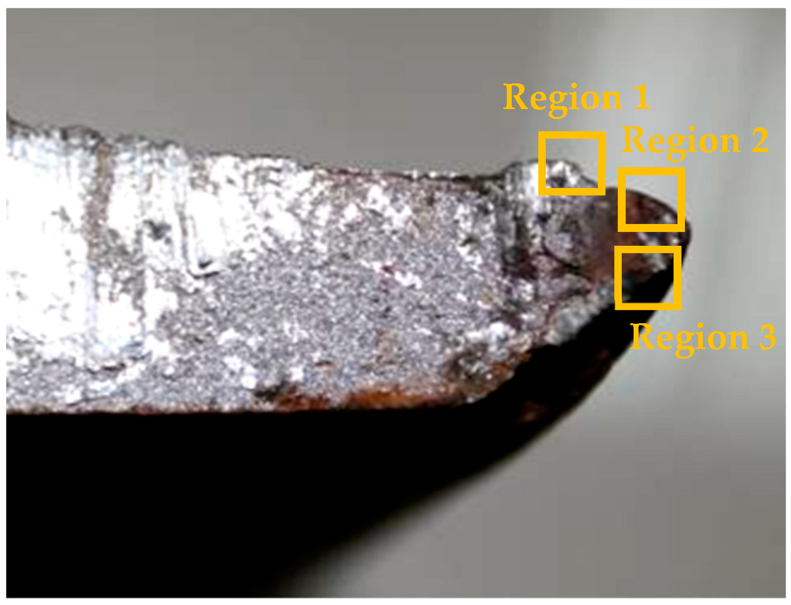
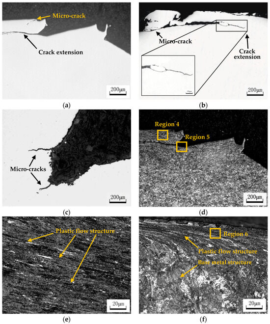
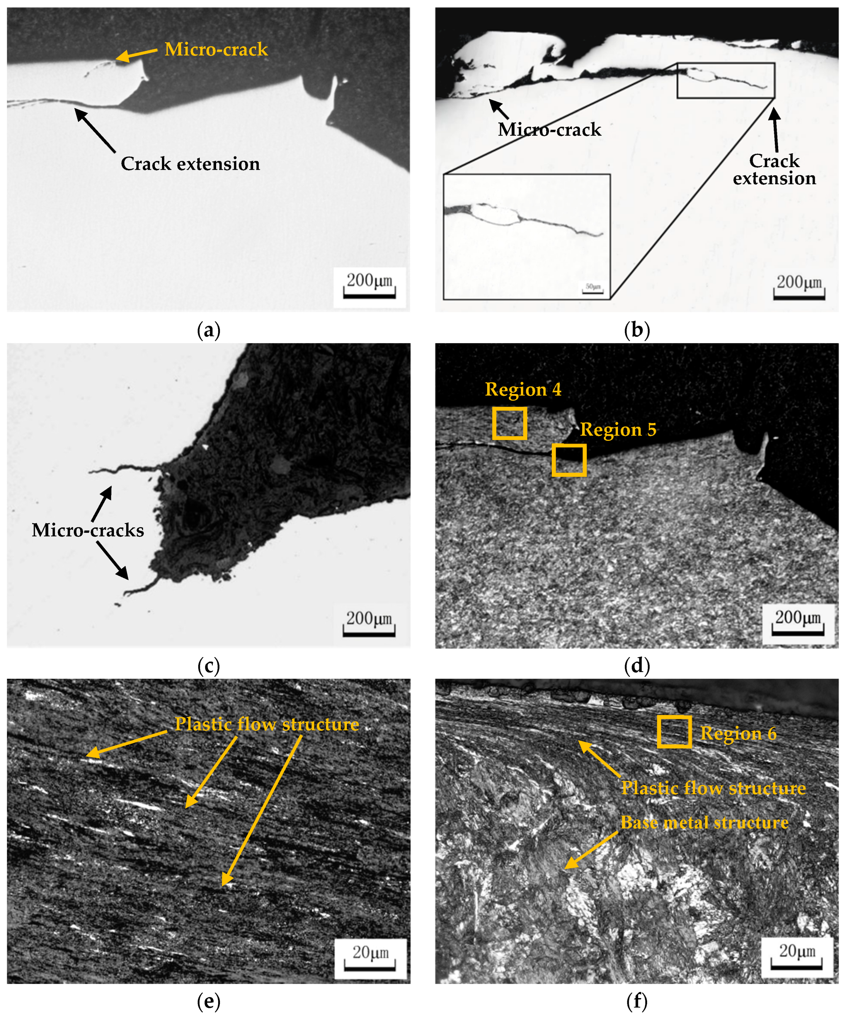
Cross-sectional specimens were extracted from the fracture origin near the rail foot. After grinding and polishing, metallographic characterization was conducted, with the sampling position marked in Figure 8 and representative metallographic images displayed in Figure 9a–c. It can be seen that multiple cracks with distinct sizes were found on the surface at the rail foot fracture origin. Several cracks propagated deep into the rail matrix, achieving a length of 200–400 μm, whereas numerous micro-cracks remained confined to the surface initiation stage without inward extension, measuring 100–200 μm in length. The main crack has already completed transverse propagation. Hence, the critical crack size responsible for fracture cannot be accurately determined, and the time span from crack initiation to final failure is also difficult to calculate precisely [35,36]. Neither abnormal nor large-sized non-metallic inclusions were detected around these cracks, and no high-temperature oxidation features were identified. These findings confirm that the local cracks were not induced by high temperature conditions during rail rolling or manufacturing processes.
Figure 8.
Observation positions of the fracture origin.
Figure 9.
Metallographic photos of the fracture origin: (a) unetched metallographic photo of region 1; (b) unetched metallographic photo of region 2; (c) unetched metallographic photo of region 3; (d) metallographic photo of region 1; (e) metallographic photo of region 4; (f) metallographic photo of region 5.
The specimen shown in Figure 9a was etched with 4 vol% nital and then observed for its metallographic structure, as shown in Figure 9d–f. Distinct plastic flow features are clearly identified in the surface metal within the fracture origin zone. The superficial microstructure is severely stretched and elongated, forming a typical fibrous flow morphology. The plastic deformed layer is approximately distributed in the range of 40–220 μm. In comparison, the internal matrix remains barely affected, and its stable metallographic structure is dominated by lamellar pearlite. Combined with the macroscopic damage characteristics on the lateral side of the rail foot, it can be clearly observed that severe plastic deformation is mainly concentrated on the lateral side of the rail foot. The plastic flow region and the crack initiation region are almost spatially overlapped and located in the same regional position. The plastic flow layer at the fracture origin is confirmed as cold deformation of the surface metal induced by external mechanical extrusion or collision. Such external mechanical loading disrupts the initial microstructure of the surface layer and drives the directional rheology of metal grains. Consequently, severe local stress concentration is generated, which provides favorable conditions for the initiation and progressive propagation of micro-cracks.
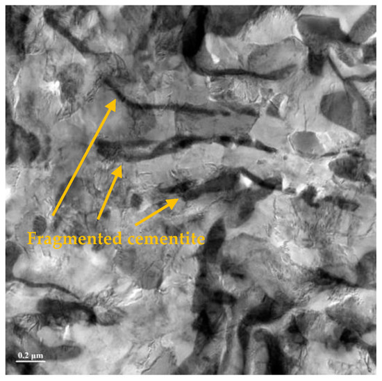
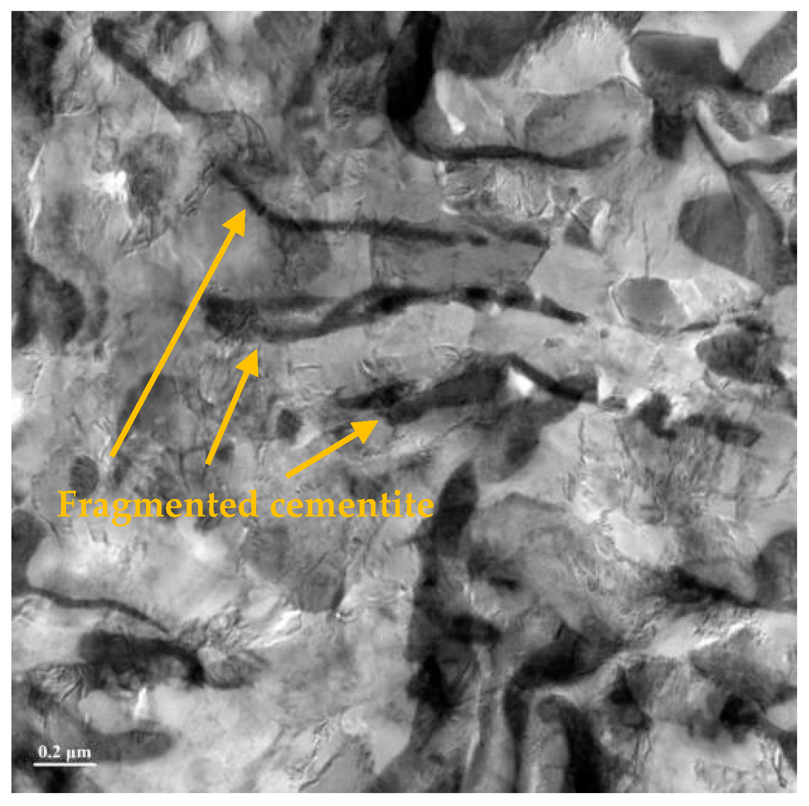
The microscopic morphology of the plastic flow microstructure in the surface layer at the fracture origin is presented in Figure 10. Within the deformed region, the original pearlite microstructure is severely destroyed, and the lamellar cementite undergoes obvious deflection and fragmentation. The length of fragmented cementite particles is about 0.6–0.8 μm, which are dispersedly distributed in the ferrite matrix. The external mechanical extrusion and impact load induce gradient plastic deformation on the rail foot surface. The microstructure degradation including pearlite distortion and cementite lamella fragmentation, significantly weakens the structural integrity and crack inhibition capability of the rail material [37]. Under the continuous cyclic wheel load, micro-cracks initiate exactly within the plastic deformed layer and then propagate inward along the weakened microstructure.
Figure 10.
The microscopic morphology of region 6.
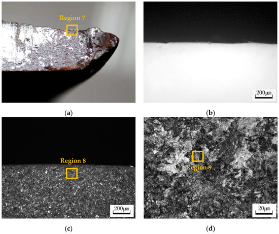
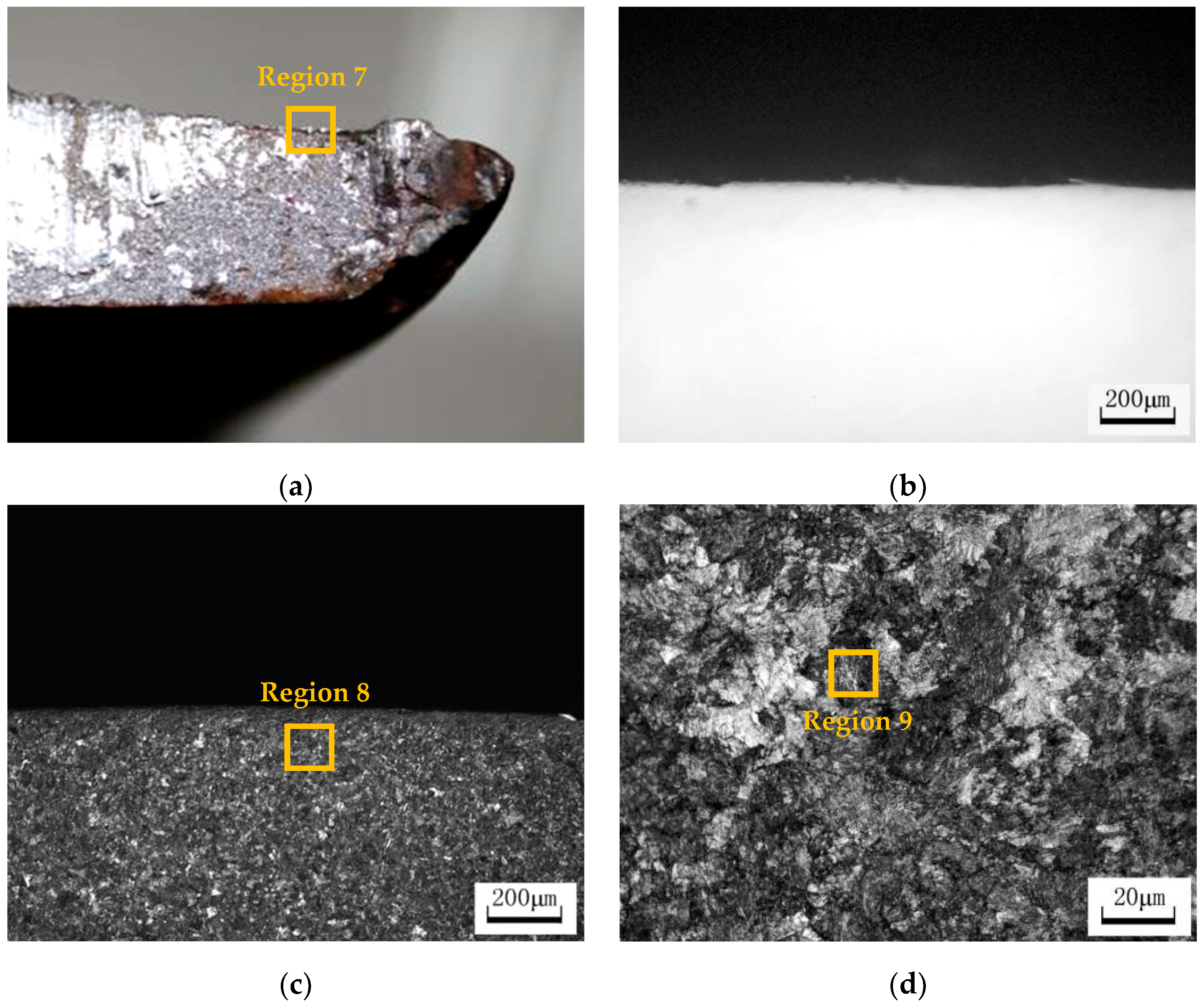
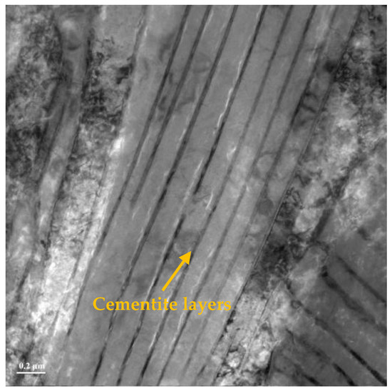
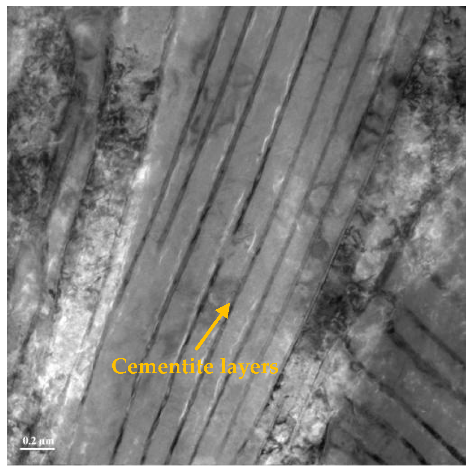
Cross-sectional specimen was taken from region beyond the fracture origin. The sampling position and metallographic photos are shown in Figure 11. In the region away from the fracture source, the surface metal remains smooth, with no visible traces of crack initiation or propagation. The microstructure consists of standard pearlite without any plastic flow characteristics. Further microstructural observation of the normal region on the fracture, as displayed in Figure 12, reveals fully preserved pearlite morphology and uniformly distributed cementite layers. This structural feature demonstrates that the local microstructure has not been affected by external extrusion or impact loading.
Figure 11.
Metallographic photos of the normal region on the fracture: (a) observation position of the normal region on the fracture; (b) unetched metallographic photo of region 7; (c) metallographic photo of region 7; (d) metallographic photo of region 8.
Figure 12.
The microscopic morphology of region 9.
3.6. Microscopic Morphology of the Fracture Surface
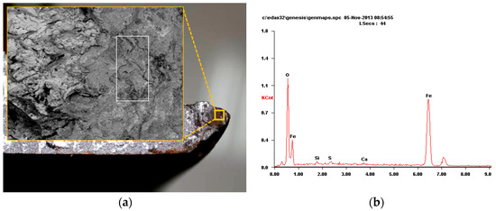
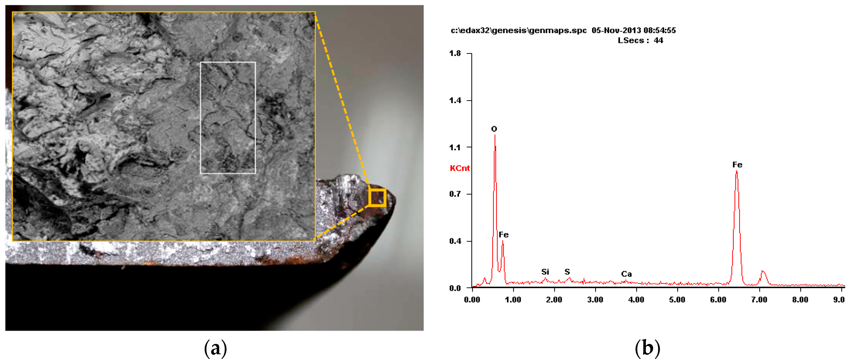
The mechanical damage of the fracture origin is dark brown, and the Energy Dispersive Spectroscopy (EDS) analysis was carried out, see Figure 13. It can be found that the main elements of the mechanical damage at the fracture origin are Fe and O, indicating that the site is covered by a rust layer. The mechanical damage should be formed early and continuously exposed to the air, resulting in corrosion. Corrosion pitting and oxide-induced stress concentration may facilitate micro-crack nucleation. Nevertheless, the stress produced by corrosion pitting and surface oxide layers is far lower than that caused by mechanical impact. Hence, their effects on micro-crack initiation are far weaker than those induced by severe plastic deformation, this issue will not be elaborated in this study.
Figure 13.
The EDS analysis results of fracture origin surface: (a) EDS photo of mechanically damage surface; (b) EDS elemental distribution.
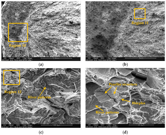
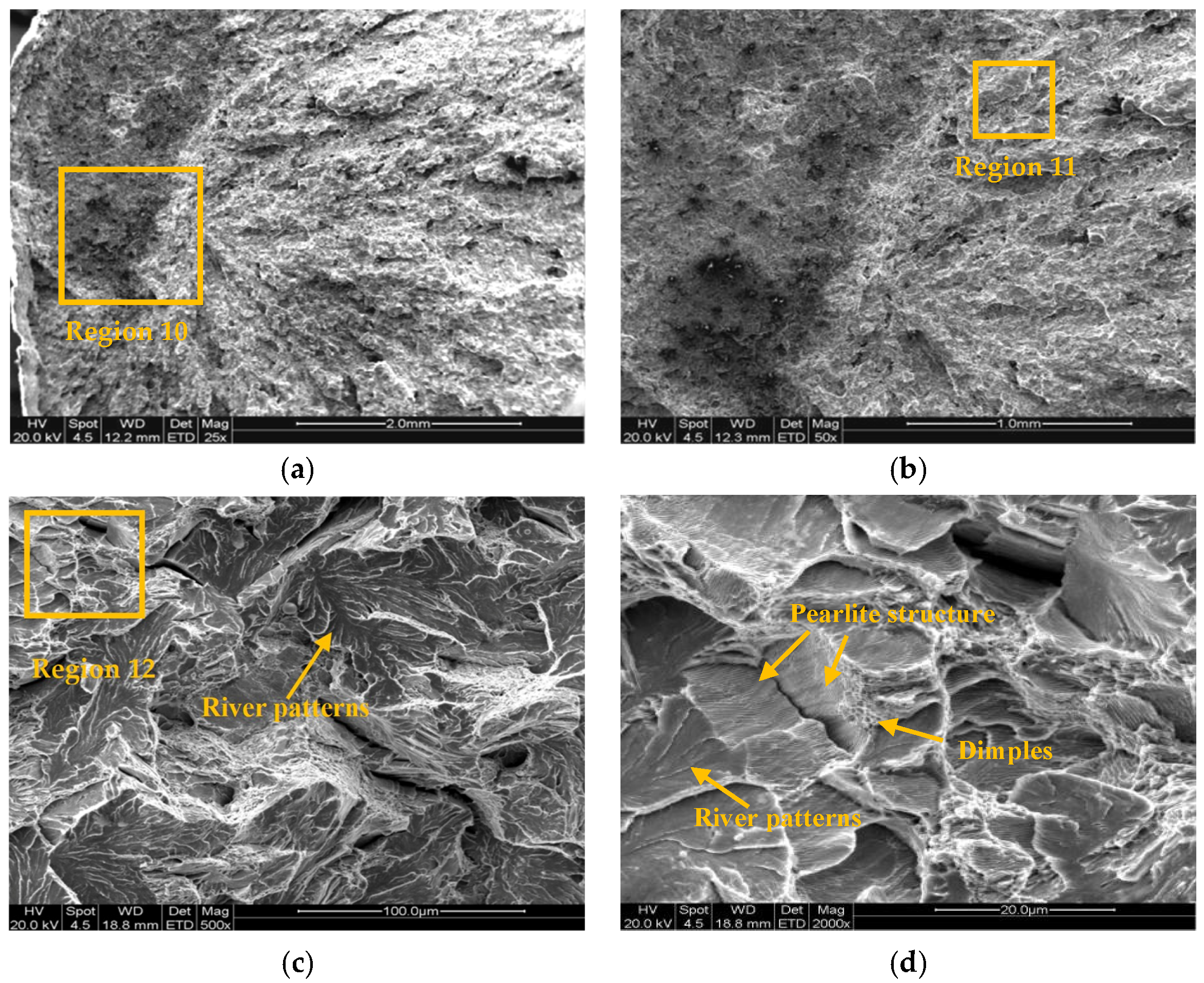
The microscopic morphology of the fracture origin surface is displayed in Figure 14. At low magnification, dense radial patterns clearly extend inward from the fracture origin into the rail matrix. No typical microscopic features of fatigue fracture, such as fatigue striations or fatigue bands, are detected, as illustrated in Figure 14a,b. Under high-magnification observation, numerous well-defined and regular cleavage steps are distributed along these radial fracture traces, which eventually forming distinctive river patterns. Meanwhile, the lamellar structure of pearlite is exposed as cracks traverse the grain interior. Only a small number of fine dimpled bands are sporadically found at individual grain boundaries, with tiny dimensions and sparse distribution, as presented in Figure 14c,d. River patterns and cleavage steps are typical microscopic features of transgranular brittle fracture, which have been widely recognized as key evidence for identifying transgranular fracture [38,39,40,41]. During brittle failure, cracks preferentially propagate along crystallographic cleavage planes with the weakest atomic bonding, forming stepped cleavage morphologies. When encountering internal grain defects, crack branches generate and converge across grain boundaries, eventually presenting typical river patterns [23,42]. As illustrated in Figure 14c,d, the fracture exhibits obvious river patterns rather than the intergranular granular morphology, further confirming the transgranular cleavage characteristic.
Figure 14.
The microscopic morphology of the fracture origin surface: (a) morphology of fracture origin; (b) high magnification of region 10; (c) high magnification of region 11; (d) high magnification of region 12.
In the pearlitic microstructure, ferrite acts as the soft phase with the {100} crystallographic plane as its preferred cleavage plane. The pearlite orientation varies significantly among individual grains, leading to diverse spatial orientations of the dominant cleavage planes. When the principal tensile stress is parallel to the pearlite lamellar direction, cracks tend to propagate along the ferrite-cementite interface. By contrast, when the principal tensile stress forms a large angle with the pearlite lamellae, or when cracks traverse adjacent grains, fracture preferentially crosses grain boundaries and produces typical river patterns on the fracture surface [38]. The visible pearlite structure inside grains in Figure 14d also provides auxiliary evidence for transgranular fracture.
Based on the above microscopic evidence, the rail fracture is dominated by transgranular cleavage. Cracks propagate swiftly along intragranular cleavage planes, manifesting as a rapid brittle fracture mode. The rail did not experience a prolonged fatigue crack propagation process before failure. Upon initiation, cracks enter a state of instantaneous unstable rapid growth, eventually resulting in catastrophic transverse fracture of the rail.
4. Discussion
During train operation, rails serve as the primary load-bearing components and are continuously subjected to complex alternating wheel-rail stresses. These stresses feature periodicity and multi-directionality, acting as the dominant inducement for rail failure. Vertical load constitutes the most critical mechanical component, whose magnitude is directly governed by train axle load and track conditions. Meanwhile, inevitable relative sliding and rotation at the wheel-rail contact interface impose additional longitudinal and lateral frictional stresses on the rail [43]. On sharp radius curved tracks, additional centrifugal force is exerted on the rail by train wheels, accompanied by severe deterioration of the wheel-rail contact condition. The contact mode transforms from surface contact to point contact, which markedly reduces the contact area. According to Hertz contact theory, contact stress is inversely proportional to contact area [44]; consequently, the stress level acting on curved track rails is considerably higher than that on straight-track.
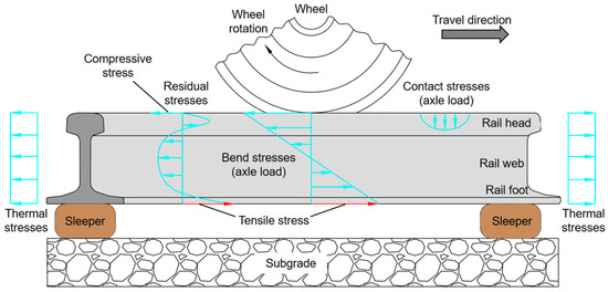
Supported by railway sleepers, the rail spanning two adjacent sleepers is subjected to a typical three-point bending state as the train wheels pass over it. The sleepers provide support at both ends, while the mid-span rail bears bending stress induced by vertical wheel load. In this state, the rail head undergoes compressive stress, whereas the rail foot is dominated by tensile stress [45]. The wheel-rail contact stress is distributed only in the shallow surface layer of the rail head, which primarily leads to rolling contact fatigue damage in the rail head rather than internal fracture initiation. In addition, rails laid on sharp radius curves are also subjected to centrifugal force generated by wheel steering. Compared with bending stress, such centrifugal force is relatively weak and mainly acts on the rail head. Residual stresses are also generated inside the rail during manufacturing processes such as forming and straightening [46]. The corresponding stress distribution on the longitudinal section of rail is presented in Figure 15.
Figure 15.
The stress distribution on the longitudinal section of rail.
In terms of bending stress and residual stress distribution, the rail head bears the maximum compressive stress, which gradually transforms into dominant tensile stress toward the rail foot. Compressive stress can effectively restrain crack propagation, whereas tensile stress remarkably promotes micro-crack initiation and growth. The rail foot is the location with the most concentrated tensile stress, and cracks tend to initiate preferentially at stress concentration sites, especially when plastic deformation already exists [38]. In addition, the rail foot possesses the smallest cross-sectional metal volume and serves as the structural weak point of the whole rail section, showing the lowest resistance to crack unstable propagation. Meanwhile, the rail foot is the outermost protruding part of the rail profile and is extremely vulnerable to external mechanical impact and extrusion during transportation, hoisting and service. Macroscopic and microscopic fracture examinations show that the rail fracture initiated at the lateral mechanical damage of the rail foot and propagated inward, the damage caused plastic flow of the surface microstructure. Typical high temperature oxidation features commonly associated with rolling manufacturing defects are not detected at the damaged region. Meanwhile, severe corrosion is observed on the fracture surface around the damaged region, indicating that the mechanical damage was generated during transportation or on-site laying and thereafter exposed to the open atmospheric environment for a prolonged period.
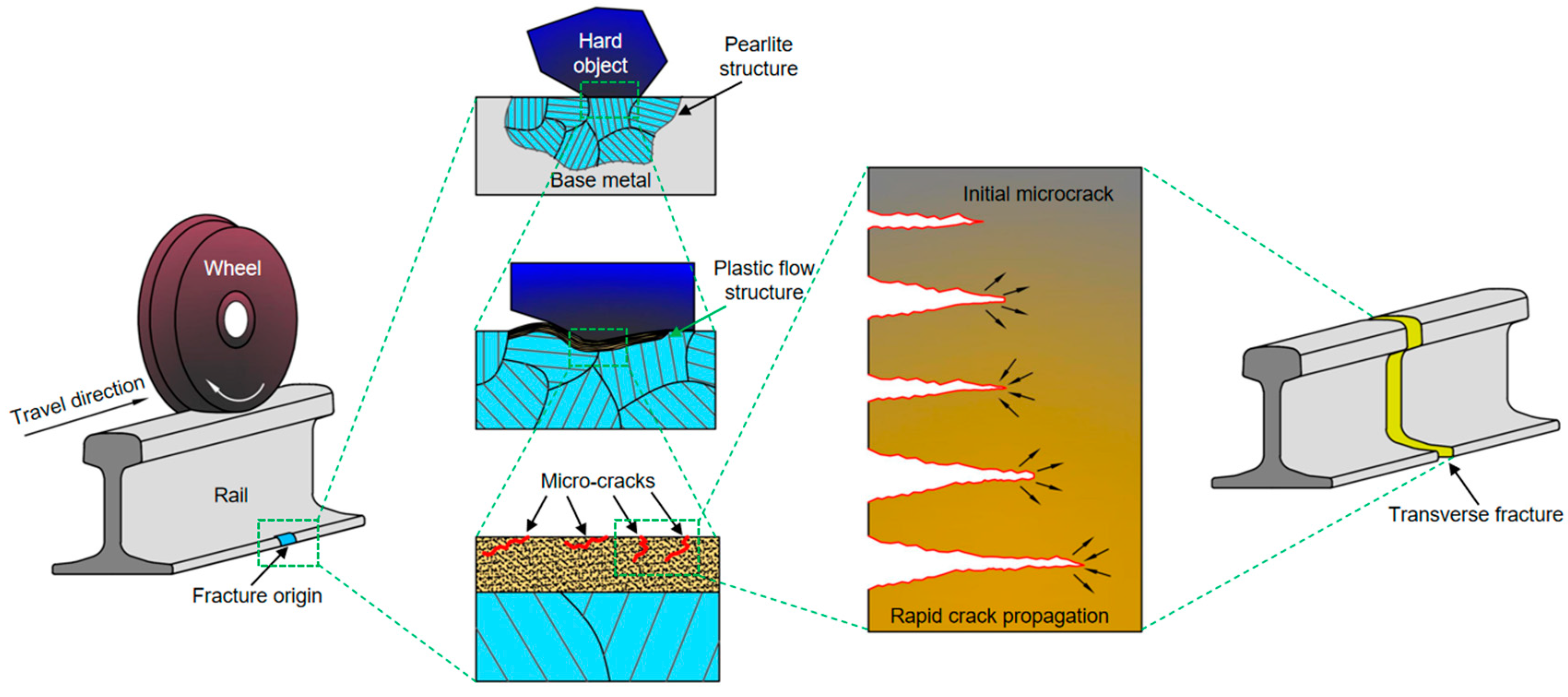
Under the instantaneous impact of severe external loads, metal crystals slip along crystal planes or grain boundaries with the weakest lattice bonding to form slip bands. With the continuous expansion and alternating movement of slip bands, micro-cracks initiate at their terminals and intersections once the applied stress exceeds the interfacial bonding strength threshold. After rail service commissioning, obvious stress concentration emerges at micro-crack tips. Under the tensile stress induced by wheel load, these micr-ocracks at the rail foot gradually open and expand, accompanied by tip blunting and limited crack extension. After wheel passage, the rail returns to its initial state, compressing the crack tips and re-sharpening them [47]. Under continuous cyclic alternating stresses from wheels, the crack tips repeatedly sharpen, blunt and propagate forward, whose mechanism is illustrated in Figure 16.
Figure 16.
The schematic diagram of the micro-cracks initiation and propagation mechanism.
The fine lamellar structure of pearlite can increase the crack propagation path, consume propagation energy, and thus exert a good inhibitory effect on crack expansion [24,48]. However, in this study, plastic flow occurs at the mechanical damage site of the rail foot, which destroys the pearlite lamellar structure and significantly reduces its inhibitory effect on crack propagation. Meanwhile, the U75V rail has a relatively high carbon content, leading to high strength and hardness but poor resistance to crack unstable propagation. As a result, cracks propagate rapidly into the rail interior, forming a transgranular brittle fracture. When the crack propagates transversely to a certain extent and the cracked area reaches a specific size, the effective cross-sectional area of the rail bearing external loads decreases. Once the external load exceeds the structural strength of the rail, the crack quickly penetrates the entire rail cross-section, resulting in rail transverse fracture.
5. Conclusions
A systematic and comprehensive inspection and analysis were carried out on the transverse fracture specimen of 60 kg/m U75V pearlitic rail on sharp radius curve track. The conclusions from this study are as follows:
- (1)
- The chemical composition, mechanical properties, non-metallic inclusions, and metallographic structure of the fractured rail base metal all meet the technical requirements of the Chinese railway standard TB/T 2344.1-2020, indicating good metallurgical quality of the rail.
- (2)
- Fracture initiation of the rail occurs at the mechanically damaged region on the rail foot side, where severe plastic deformation takes place in the surface metal. Micro-cracks nucleate within the plastic flow structure and propagate inward into the substrate. Distinct cleavage steps and river patterns are clearly observed on the fracture surface, confirming that the failure belongs to typical brittle fracture.
- (3)
- Mechanical external forces acting on the lateral side of the rail foot cause plastic deformation, leading to the initiation of micro-cracks. The pearlite structure is damaged, with the lamellae of cementite broken and deflected, which impairs its ability to inhibit crack propagation. Under the action of cyclic alternating loads from the wheel, these micro-cracks propagate rapidly inward to form transgranular cracks, eventually resulting in transverse fracture of the rail.
- (4)
- Railway construction and operation personnel shall standardize their operation procedures, strengthen the management of rail construction, and avoid mechanical external damage to the rail during hoisting, transportation, and track-laying processes. Meanwhile, regular inspections of the track shall be conducted, and rails with mechanical damage shall be promptly replaced.
Author Contributions
Conceptualization, J.F., H.Q. and L.Z.; methodology, J.F., B.Y. and L.Z.; validation, H.Q. and B.Y.; formal analysis, J.F., H.Q., B.Y., M.W. and L.Z.; investigation, J.F., B.Y. and M.W.; resources, H.Q. and L.Z.; data curation, M.W.; writing—original draft preparation, J.F.; writing—review and editing, J.F., H.Q., B.Y., M.W. and L.Z.; visualization, J.F. and M.W.; funding acquisition, J.F. and L.Z. All authors have read and agreed to the published version of the manuscript.
Funding
This research was funded by Hubei Provincial Natural Science Foundation of China (No. 2025AFB604).
Data Availability Statement
The original contributions presented in this study are included in the article. Further inquiries can be directed to the corresponding author.
Conflicts of Interest
The authors declare no conflicts of interest. The funders had no role in the design of the study; in the collection, analyses, or interpretation of data; in the writing of the manuscript; or in the decision to publish the results.
References
- Chen, F.; Chen, Z. High-speed Rail and Happiness. Transp. Res. Part A Policy Pract. 2023, 170, 103635. [Google Scholar] [CrossRef] [Scilit]
- Zhai, W.; Stichel, S.; Ling, L. Train-track Coupled Dynamics Problems in Heavy-haul Rail Transportation. Veh. Syst. Dyn. 2025, 63, 1187–1240. [Google Scholar] [CrossRef] [Scilit]
- Huang, L.; Li, Z.; An, Q. Calculation Method of Wheel/Rail Contact Stress when Passing Through Curved Track. J. East China Univ. Sci. Technol. (Nat. Sci. Ed.) 2017, 43, 133–142. [Google Scholar] [CrossRef]
- Honjo, M.; Kimura, T.; Hase, K. Effect of Cr on Lamellar Spacing and High-temperature Stability in Eutectoid Steels. ISIJ Int. 2016, 56, 161–167. [Google Scholar] [CrossRef] [Scilit]
- Gren, D.; AhlstrÖm, J.; Ekh, M. Fatigue Crack Characteristics in Gradient Predeformed Pearlitic Steel under Multiaxial Loading. Adv. Eng. Mater. 2024, 26, 2400950. [Google Scholar] [CrossRef] [Scilit]
- Jabońska, M.; Lewandowski, F.; Chmiela, B.; Gronostajski, Z. Advanced Heat Treatment of Pearlitic Rail Steel. Materials 2023, 16, 6430. [Google Scholar] [CrossRef] [Scilit] [PubMed]
- Yadav, R.K.; Ajit, K.P. A New Stress-based Model to Predict the Fatigue Life of 880-grade Pearlitic Rail Steel under Uniaxial Ratcheting Conditions. Int. J. Fatigue 2023, 171, 107588. [Google Scholar] [CrossRef] [Scilit]
- Nielsen, J.C.; Abrahamsson, T.J.; Ekberg, A. Probability of Instant Rail Break Induced by Wheel-rail Impact Loading Using Field Test Data. Int. J. Rail Transp. 2022, 10, 1–23. [Google Scholar] [CrossRef] [Scilit]
- Santa, J.F.; Cuervo, P.; Christoforou, P.; Harmon, M.; Beagles, A.; Toro, A.; Lewis, R. Twin Disc Assessment of Wear Regime Transitions and Rolling Contact Fatigue in R400HT-E8 Pairs. Wear 2019, 432, 102916. [Google Scholar] [CrossRef] [Scilit]
- Freisinger, M.; Rojacz, H.; Trausmuth, A.; Mayrhofer, P.H. Severe Plastic Deformed Zones and White Etching Layers Formed During Service of Railway Wheels. Metallogr. Microstruct. Anal. 2023, 12, 515–527. [Google Scholar] [CrossRef] [Scilit]
- Song, J.; Shi, L.; Ding, H.; Galas, R.; Omasta, M.; Wang, W.; Guo, J.; Liu, Q.; Hartl, M. Effects of Solid Friction Modifier on Friction and Rolling Contact Fatigue Damage of Wheel-rail Surfaces. Friction 2022, 10, 597–607. [Google Scholar] [CrossRef] [Scilit]
- Torskaya, E.V.; Goryacheva, I.G.; Shur, E.A. Rolling Contact Fatigue Damage in Welded Rail Steel Joints. Phys. Mesomech. 2023, 26, 7–18. [Google Scholar] [CrossRef] [Scilit]
- Wang, H.; Ding, H.; Zhang, S.; Shi, Z.; Meli, E.; Wang, W.; Lewis, R.; Liu, Q.; Zhou, Z. Quantitative Characterization of The Relationship Between Wear and Rolling Contact Fatigue of Rail Material. Wear 2025, 578–579, 206169. [Google Scholar] [CrossRef] [Scilit]
- Han, Z.; Wang, H.; Wang, W.; Zhang, S.; Lin, D.; Wang, Y.; Ding, H.; Zhou, Z.; Liu, Q. The Correlation Between Material Deformed Microstructure and Rolling Contact Fatigue Crack Propagation of U71Mn Rail When Matching with CL60 Wheel. Tribol. Int. 2024, 200, 110069. [Google Scholar] [CrossRef] [Scilit]
- Zhang, S.; Zhao, H.; Ding, H.; Lin, Q.; Wang, W.; Guo, J.; Wang, P.; Zhou, Z. Effect of Vibration Amplitude and Axle Load on The Rail Rolling Contact Fatigue Under Water Condition. Int. J. Fatigue 2023, 167, 107329. [Google Scholar] [CrossRef] [Scilit]
- Leso, T.P.; Siyasiya, C.W.; Mostert, R.J.; Moema, J. Effects of Lubrication on Wear and Rolling Contact Fatigue Behavior of Class B Wheel Steels Against R350HT Rail Steels Using a Twin-Disc Wear Simulator. Tribol. Trans. 2023, 66, 623–633. [Google Scholar] [CrossRef] [Scilit]
- Leso, T.P.; Siyasiya, C.W.; Mostert, R.J.; Moema, J. Study of Rolling Contact Fatigue, Rolling and Sliding Wear of Class B Wheel Steels Against R350HT and R260 Rail Steels Under Dry Contact Conditions Using The Twin Disc Setup. Tribol. Trans. 2022, 174, 107711. [Google Scholar] [CrossRef] [Scilit]
- Elsiddig, E.S.; Ahlatci, H.; Demir, B.; Esen, I.; Al-hemyari, F.H. Mechanistic Insight into Wear-Rolling Contact Fatigue Interaction in ER7 Wheel Steel Against R260 and R350HT Rails. Wear 2026, 598, 206759. [Google Scholar] [CrossRef] [Scilit]
- Cuervo, P.A.; Toro, A.; Meza, J.M.; Santa, J.F.; Lewis, R. A Twin-disc Study of The Role of The Surface Quality Achieved By Grinding on The Wear Resistance and Rolling Contact Fatigue Behavior of Wheel/rail Pairs. Proc. Inst. Mech. Eng. Part F J. Rail Rapid Transit 2024, 238, 394–405. [Google Scholar] [CrossRef] [Scilit]
- Li, J.; Zhou, Y.; Cheng, Z.; Wang, C.; Weng, Z. Evolution of Microscopic Characteristics of Rolling Contact Fatigue Coexisting with Wear of U75V Rail. Tribol. Int. 2023, 190, 109041. [Google Scholar] [CrossRef] [Scilit]
- Zhang, Q. Fracture Causes and Prevention Measures of Mobile Flash Welding Joint. Railw. Eng. 2022, 62, 54–58. [Google Scholar] [CrossRef]
- Mueller, E.M.; Liu, X. Failure Analysis and Finite Element Modelling of a Rail Axle Fatigue Fracture. Int. J. Railw. Technol. 2018, 7, 45–63. [Google Scholar] [CrossRef] [Scilit]
- Hjertsén, D.; Ekberg, A.; Vernersson, T. Railway wheel failure caused by flange crack, part 1: Background and failure analysis. Eng. Fail. Anal. 2026, 191, 110770. [Google Scholar] [CrossRef] [Scilit]
- Leonetti, D.; Ferreira, V.M.; Schotsman, B. Fracture Behavior and Mechanical Characterization of R350HT Rail Steel. Procedia Struct. Integr. 2023, 47, 219–226. [Google Scholar] [CrossRef] [Scilit]
- Sjoerd, T.H.; Davide, L.; Snijder, H.H.; Maljaars, J. Mixed Mode Fracture Toughness of R260Mn Rail Steel Using Compact Tension Shear Specimens. Procedia Struct. Integr. 2025, 68, 1216–1222. [Google Scholar] [CrossRef] [Scilit]
- Seo, J.; Kwon, S.; Jun, H.; Lee, D. Evaluation of Fatigue and Fracture Characteristics of High-Speed Rail Material. J. Korean Soc. Precis. Eng. 2017, 34, 861–866. [Google Scholar] [CrossRef] [Scilit]
- Jun, H.; Seo, J.; Jeon, I.; Lee, S.; Chang, Y. Fracture and Fatigue Crack Growth Analyses on A Weld-repaired Railway Rail. Eng. Fail. Anal. 2026, 59, 478–492. [Google Scholar] [CrossRef] [Scilit]
- Al-Juboori, A.; Zhu, H.; Li, H.; McLeod, J.; Pannila, S.; Barnes, J. Microstructural Investigation on A Rail Fracture Failure Associated with Squat Defects. Eng. Fail. Anal. 2023, 151, 107411. [Google Scholar] [CrossRef] [Scilit]
- Godefroid, L.B.; Faria, G.L.; Cândido, L.C.; Viana, T.G. Failure Analysis of Recurrent Cases of Fatigue Fracture in Flash Butt Welded Rails. Eng. Fail. Anal. 2015, 58, 407–416. [Google Scholar] [CrossRef] [Scilit]
- Nguyen, B.H.; Al-Juboori, A.; Zhu, H.; Gazder, A.; Li, H.; Tieu, K. Fracture Mechanisms in Rails with Mechanically and Thermomechanically-induced White Etching Layers Under Three-point Bending. Eng. Fail. Anal. 2022, 131, 105813. [Google Scholar] [CrossRef] [Scilit]
- Xu, X.; Yang, Q.; Zhong, J.; Lyu, J.; Zhang, Q.; Wang, Y.; Wang, X. Fracture Causes Analysis on Flash Welding Joint of 60 kg/m U75V Rail. Railw. Eng. 2022, 62, 59–62. [Google Scholar] [CrossRef]
- Chen, L.; Zhu, H.; Wu, D.; Zhang, Z. Cause Analysis of Straightening Fracture of 60N U75V Rail. Adv. Mater. High Speed Railw. 2023, 2, 69–74. [Google Scholar] [CrossRef]
- Wang, R.; Zhou, J.; Zhu, M.; Liu, F.; Li, C.; Fei, J.; Zheng, J.; Xu, Z. Analysis of Reasons for Sawing Fracture of U75V Rail. China Railw. Sci. 2018, 39, 50–55. [Google Scholar] [CrossRef]
- TB/T 2344.1-2020; Rails—Part 1: 43kg/m~75kg/m Rails. National Railway Administration of China: Beijing, China, 2020.
- Xu, D.; Liu, G.; Wang, X.; Liu, H. Experimental Study on Fatigue Performance of Steel Used in U75V Rails. Materials 2025, 18, 4706. [Google Scholar] [CrossRef] [Scilit]
- Seo, J.W.; Hur, H.M.; Kwon, S.J. Effect of Mechanical Properties of Rail and Wheel on Wear and Rolling Contact Fatigue. Metals 2022, 12, 630. [Google Scholar] [CrossRef] [Scilit]
- Yuriev, A.A.; Gromov, V.E.; Grishunin, V.A.; Ivanov, Y.F.; Qin, R.; Semin, A.P. Stages and Fracture Mechanisms of Lamellar Pearlite of 100m-Long Differentially Hardened Rails Under Long-Term Operation Conditions. Acta Metall. Sin. 2018, 31, 1356–1360. [Google Scholar] [CrossRef] [Scilit]
- Dong, Y.; Miao, M.; Duan, R.; Liu, Y.; Wang, K.; Wu, X.; Chen, S. Microstructural Characteristics and Fracture Behavior of the Rotor Magnetic Pole Screw in an Industrial Synchronous Motor. Coatings 2026, 16, 282. [Google Scholar] [CrossRef] [Scilit]
- Du, H.; Yang, G.; Xu, C.; Zhang, Q.; Feng, B.; Liu, J.; Liu, F. Experimental Study on Toughness and Microscopic Characteristics of U71Mn Rail Under Plateau Extreme Cold Conditions. Adv. Mater. High Speed Railw. 2025, 4, 17–23. [Google Scholar] [CrossRef]
- Zhao, X.; Zhang, Z.; He, Z.; Han, Y.; Yuan, J. Failure Causes Analysis of Circumferential Cracking on Gathering Pipeline in M Oil and Gas Field. Coatings 2024, 14, 770. [Google Scholar] [CrossRef] [Scilit]
- Takahashi, A.; Toyohiro, T.; Segawa, Y.; Kobayashi, M.; Miura, H. Embrittlement Fracture Behavior and Mechanical Properties in Heat Affected Zone of Welded Maraging Steel. Materials 2024, 17, 440. [Google Scholar] [CrossRef] [Scilit]
- Chen, M.; Li, N.; Gigax, J.; Hunter, A.; Fensin, S.; Zikry, M.A. How are microstructural defect interactions linked to simultaneous intergranular and transgranular fracture modes in polycrystalline systems? J. Mech. Phys. Solids 2024, 188, 105674. [Google Scholar] [CrossRef] [Scilit]
- Wang, M.; Su, H.; Yan, Z.; Chen, C.; Zheng, C.; Lv, B.; Zhang, F. A Review of Experimental and Simulation Methods for Rolling Contact Fatigue. Metals 2026, 16, 168. [Google Scholar] [CrossRef] [Scilit]
- Srivastava, J.P.; Sarkar, P.K.; Ranjan, V. Contact Stress Analysis in Whee-Rail by Hertzian Method and Finite Element Method. J. Inst. Eng. (India) Ser. C 2014, 95, 319–325. [Google Scholar] [CrossRef] [Scilit]
- Tawfik, M.N.; Padzi, M.M.; Abdullah, S.; Harmanto, D.; Firdaws, M.N.; Hapaz, H. A Review of the Rolling Contact Fatigue of Rail Wheels Under Various Stresses. J. Fail. Anal. Prev. 2023, 23, 16–29. [Google Scholar] [CrossRef] [Scilit]
- Zerbst, U.; Lundén, R.; Edel, K.O.; Smith, R.A. Introduction to The Damage Tolerance Behaviour of Railway Rails—A Review. Eng. Fract. Mech. 2009, 76, 2563–2601. [Google Scholar] [CrossRef] [Scilit]
- Akama, M. Rolling Contact Fatigue and Wear of Rails and Wheels: A Comprehensive Review. Machines 2025, 13, 970. [Google Scholar] [CrossRef] [Scilit]
- Krolicka, A.; Lesiuk, G.; Radwanski, K.; Kuziak, R.; Janik, A.; Mech, R.; Zygmunt, T. Comparison of fatigue crack growth rate: Pearlitic rail versus bainitic rail. Int. J. Fatigue 2021, 149, 106280. [Google Scholar] [CrossRef] [Scilit]



Disclaimer/Publisher’s Note: The statements, opinions and data contained in all publications are solely those of the individual author(s) and contributor(s) and not of MDPI and/or the editor(s). MDPI and/or the editor(s) disclaim responsibility for any injury to people or property resulting from any ideas, methods, instructions or products referred to in the content. |
© 2026 by the authors. Licensee MDPI, Basel, Switzerland. This article is an open access article distributed under the terms and conditions of the Creative Commons Attribution (CC BY) license.