Article

Dependence of Intragranular Orientation Gradients on Grain Orientation in Cold-Rolled Fe-3%Si Steel


1
School of Mechanical Engineering and Automation, Dalian Polytechnic University, Dalian 116034, China
2
Baotai Group Co., Ltd., Baoji 721014, China
3
Key Laboratory for Anisotropy and Texture of Materials (Ministry of Education), Northeastern University, Shenyang 110819, China
*
Author to whom correspondence should be addressed.
Metals 2026, 16(6), 584; https://doi.org/10.3390/met16060584
Submission received: 30 April 2026 / Revised: 21 May 2026 / Accepted: 23 May 2026 / Published: 26 May 2026
(This article belongs to the Special Issue Rolling and Forming of Alloys and Steels)

Abstract

Intragranular orientation gradients play a critical role in deformation and recrystallization texture evolution of silicon steel. In this study, the dependence of intragranular orientation gradients on grain orientation in a cold-rolled Fe-3%Si alloy was systematically investigated through electron backscatter diffraction (EBSD), complemented by a rate-dependent crystal plasticity model, incorporating grain boundary resistance. A comparative assessment of intragranular orientation gradients in the grain core and grain boundary regions revealed that they are markedly sensitive to grain orientation, with the grain boundary region exhibiting a higher orientation gradient than the grain core. The formation of intragranular orientation gradients is governed by the orientation stability during plastic deformation: stable convergent α (<110>//RD, rolling direction) and γ (<111>//ND, normal direction) orientations develop lower orientation gradients, whereas grains with unstable divergent λ (<001>//ND) orientations exhibit higher orientation gradients. Furthermore, intergranular interactions during rolling reduce orientation stability near grain boundaries, thereby promoting higher orientation gradients in the grain boundary region compared to the grain core.

1. Introduction

As a critical soft magnetic material for motors, generators, and transformers, silicon steel is indispensable in advanced engineering fields, including manned spaceflight, new energy vehicles, and large-scale hydropower systems [1,2,3,4]. Its magnetic properties, namely magnetic induction and iron loss, are strongly governed by crystallographic texture due to magnetocrystalline anisotropy [5,6,7]. Grains often undergo orientation splitting during plastic deformation, leading to the formation of intragranular orientation gradients. The emergence of intragranular orientation gradients not only alters the deformation texture but also significantly influences the nucleation and growth environment of subsequent recrystallization. Therefore, the precise characterization and control of intragranular orientation gradients are vital for texture optimization of silicon steel.
The formation of intragranular orientation gradients is closely associated with the externally applied strain state, the strain gradients developed within a grain, the incompatibility with neighboring grains, and the orientation stability of a grain during plastic deformation. During plastic deformation, the grain interior is able to rotate relatively freely, whereas lattice rotation in the vicinity of grain boundaries is restricted due to the additional constraints imposed by neighboring grains, thereby resulting in a curvature of lattice planes. The lattice curvatures and strain gradients present in these regions are accommodated by geometrically necessary dislocations (GNDs), which possess identical Burgers vectors and line directions [8,9]. As a consequence of slip incompatibility between grains, GNDs accumulate at grain boundaries. On the one hand, these GNDs act as obstacles to dislocation motion, contributing to forest hardening; on the other hand, their spatially heterogeneous distribution generates back stresses [10,11], which in turn lead to the development of orientation gradients in the regions adjacent to grain boundaries. Moreover, grains usually contain slight initial orientation perturbations before plastic deformation. A stable orientation exhibits minimal rotation during deformation, causing any initial, slightly perturbed sub-orientations within the grain to converge toward it, thereby minimizing the final orientation spread. Conversely, an unstable orientation tends to rotate, and minor initial perturbations can evolve along divergent rotation paths, leading to significant orientation gradients even in the absence of strain gradients [12,13].
In body-centered cubic (BCC) metals, λ (<001>//ND, normal direction), α (<110>//RD, rolling direction), and γ (<111>//ND) are the predominant texture components in cold rolling [14,15]. Extensive prior studies have reported intragranular orientation gradients in λ- and α-oriented grains during cold rolling. Sha et al. [16] pointed out that deformed grains with orientations near λ, such as {001}<210>, {114}<841>, and {113}<631>, develop orientation gradients during cold rolling and form cubic-oriented nuclei in subsequent recrystallization. Similarly, Jiao et al. [17] observed that deformation bands within {223}<110>–{001}<110> oriented grains provide sites for {114}<841> and {112}<241> recrystallized nuclei. Quadi and Duggan [18] reported that α-oriented grains in interstitial-free (IF) steel deformed uniformly at low reductions but exhibited orientation splitting above an 85% rolling reduction. In contrast, γ (<111>//ND)-oriented grains typically develop Goss-oriented shear bands during cold rolling [19,20], whereas deformation bands are rarely observed in γ-oriented grains. Coordinated deformation between neighboring grains results in the grain boundary region having a different orientation gradient from that of the grain core [21,22]. Zaefferer et al. [23] reported that low-angle boundaries induce minor orientation changes near boundaries, whereas high-angle boundaries lead to significant gradient zones in grain boundary regions. The width of such gradient zones correlates with the Taylor factor ratio between neighboring grains [24], while dislocation transmission mechanisms hindered by high-angle boundaries further influence the local deformation response [25].
In recent years, electron backscatter diffraction (EBSD) has become the standard technique for quantifying intragranular orientation gradients using parameters such as grain orientation spread (GOS), grain reference orientation deviation (GROD), and kernel average misorientation (KAM) [26,27,28,29]. Moreover, the implementation of crystal plasticity theory within a finite element framework has rendered the crystal plasticity finite element method (CPFEM) an effective tool for predicting deformation heterogeneity. Within grain interiors, CPFEM predicts orientation gradients through strain heterogeneity at different locations or by introducing initial intragranular orientation perturbations [30]. For grain boundary regions, traditional CPFEM can only simulate deformation heterogeneity via grain boundary geometry and misorientation; it lacks the essential mechanisms of dislocation–grain boundary interactions and therefore cannot faithfully capture orientation gradients near grain boundaries. Consequently, considerable research efforts have been devoted to incorporating dislocation–grain boundary interactions into crystal plasticity models. Lim et al. [31] incorporated both the back stress that impedes dislocation motion and the resistance to dislocation transmission at grain boundaries into a crystal plasticity model, thereby enabling the simulation of heterogeneity in grain boundary regions. Chakraborty et al. [32] developed a crystal plasticity material model that accounts for both dislocation transport within grains and dislocation transfer across grain boundaries. Zhang et al. [10] established a nonlocal crystal plasticity model by introducing a flux term to account for the spatial redistribution of dislocations due to their motion. In a separate study, Zhang et al. [33] quantitatively characterized GNDs in crept P91 steel using a finite element method that treats crystal orientation as a field variable. Strain-gradient viscoplastic self-consistent models [34] and elastoplastic self-consistent models [35] have also played important roles in simulating the evolution of GNDs in polycrystalline metals. Furthermore, molecular dynamics (MD) investigations into dislocation mobility, dislocation–grain boundary interactions, and strain localization [36,37] provide an effective means for characterizing microstructural evolution at the atomic scale.
While existing studies highlight the sensitivity of intragranular orientation gradients to grain orientation, most investigations mainly focus on characterizing gradient magnitude through EBSD parameters. A systematic and quantitative analysis of how intragranular orientation gradients depend on grain orientation, particularly comparing grain core and boundary regions, is still lacking. Therefore, the present study combines EBSD with crystal plasticity calculations to quantitatively investigate the dependence of intragranular orientation gradients on grain orientation in a cold-rolled Fe-3%Si alloy. This work clarifies the roles of orientation stability and grain–grain interactions in intragranular orientation gradient formation, providing a clearer mechanistic basis for texture control during silicon steel processing.

2. Materials and Methods

2.1. Experimental Methods

Intragranular orientation gradients in a cold-rolled Fe-3%Si alloy were characterized using a Crossbeam 550 scanning electron microscope (SEM, JEOL, Tokyo, Japan) equipped with an EBSD system. The initial material consisted of a normalized Fe-3%Si alloy sheet with a thickness of 2.2 mm, which was cold-rolled to 1.25 mm and subsequently subjected to intermediate annealing at 1050 °C for 4 min. This treatment resulted in a fully recrystallized microstructure with an average grain size of approximately 90 μm, which was used as the starting material for the present study. First, the initial texture was examined using EBSD with a step size of 3 μm. Subsequently, the Fe-3%Si alloy sheet was subjected to 65% cold-rolling deformation. After electrolytic polishing, the deformation texture was characterized again using EBSD with a step size of 0.4 μm.
Based on the acquired EBSD data, the grain reference orientation deviation (GROD) and grain orientation spread (GOS) parameters were employed to quantify intragranular orientation gradients within deformed grains. As defined in Equations (1) and (2), GROD represents the angular deviation of each measurement point from the average orientation of all points within the grain, whereas GOS corresponds to the average GROD value across all measurement points within a grain.
GROD p i = β p 0 , p i
GOS p i = 1 n i = 1 n β p 0 , p i
Here, p0 denotes the average orientation of all measured points within a given grain, pi is the orientation of the i-th measured point, β(p0, pi) signifies the misorientation angle between p0 and pi, and n represents the total number of measured points within the grain [38].
Furthermore, the GROD values in grain core and at grain boundaries were compared. The minimum distance from test point i to all the grain boundaries within the current grain is defined as the distance from the test point to the grain boundary. Measurement points within 3 μm of a grain boundary were defined as the grain boundary region. This distance limit was chosen based on two considerations. First, it has been reported that the width of the grain boundary region in 75% cold-rolled steel is approximately 2 μm [39]. Second, it was necessary to ensure that the defined grain boundary region accounted for a proportion of the microstructure that is neither unreasonably high nor low. When the distance limit was set to 3 μm, the grain boundary region comprised 25% of the total area. A larger distance limit would have resulted in an unreasonably high proportion. Furthermore, the indexing rate of EBSD pixels in the grain boundary region is lower than that in the grain interior. A smaller distance limit would reduce the number of usable measurement points in the grain boundary region, thereby introducing bias into the characterization of orientation gradients near grain boundaries. The selected EBSD step size of 0.4 μm after deformation provides sufficient spatial resolution to resolve the orientation gradient features of the grain core and grain boundary regions. This ensures that the measured orientation gradients are free from step-size-induced artifacts. The EBSD data were processed using AztecCrystal 3.1 (Oxford Instruments, Abingdon, UK) and MTEX toolbox to analyze intragranular orientation gradients in the grain core and grain boundary regions.

2.2. Computational Procedure

Orientation rotation during cold rolling was calculated using a crystal plasticity framework [40,41]. Deformation velocity gradient L can be decomposed into a symmetric plastic strain rate ε ˙ and an anti-symmetric material spin W ˙ :
L   =   ε ˙ + W ˙
Plastic strain rate ε ˙ is contributed by slip rates γ ˙ of all slip systems:
ε ˙   =   1 2 α K s α m α + m α s α γ ˙ α
For grain interiors away from grain boundaries, a rate-dependent model is adopted to calculate slip rate:
γ ˙ α = a ˙ α τ α g α n sgn ( τ α )
where a ˙ α = 0.001 s−1 is reference strain rate and n = 20 is rate sensitivity exponent. τ α and g α are resolved shear stress and strength of αth slip system. Grain boundaries usually act as obstacles to dislocation movement, so grain boundary obstacle stress (τobs) is incorporated as resistance into slip system activation for grain boundary regions [31]:
γ ˙ α   =   a ˙ α τ eff α g α n sgn ( τ eff α )
τ eff α = τ α τ obs α ( τ α   >   τ obs α )
  τ eff α = 0 ( τ α     τ obs α )
τobs can be calculated by slip transmissivity (N) at the grain boundary:
τ obs   =   ( 1     N ) τ *
N = ( L 1 · L i )   ×   ( s 1 · s i )
Slip transmissivity depends on the grain boundary direction and the geometry of the slip systems. L1 represents the intersection line between grain boundary and slip plane of incoming dislocation. Li is the intersection line between grain boundary and slip plane of emitted dislocation in neighboring grain. s1 and si are slip directions of incoming dislocation and emitted dislocation, respectively. The maximum obstacle stress of grain boundary τ * is estimated to be 1.1 GPa [31]. Slip transmissivity ranges from 0 to 1, corresponding to the maximum and minimum obstacle stress. For a given incoming slip system, τobs is selected as the minimum value among all allowed emitted slip systems. Twenty-four slip systems (12×{110}<111>, 12×{112} <111>) are considered for body-centered cubic (bcc) non-oriented silicon steels.
Rotation vector g ˙   =   ( φ ˙ 1 ,   Φ ˙ ,   φ ˙ 2 ) can be calculated when lattice spin is defined with respect to sample reference frame:
φ ˙ 1 =   Ω ˙ 12 φ ˙ 2 cos Φ
Φ   ˙ = Ω ˙ 23 cos φ 1 Ω ˙ 31 sin φ 1
φ ˙ 2   = ( Ω ˙ 23 sin φ 1 +   Ω ˙ 31 cos φ 1 ) / sin Φ

3. Results

3.1. Initial Texture and Cold-Rolling Texture

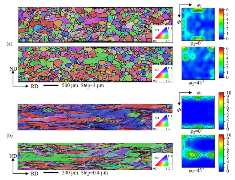
Figure 1 presents the orientation image maps (OIMs) and corresponding orientation distribution function (ODF) sections for the Fe-3%Si alloy sheet in the initial state and after cold rolling. The macrotexture of the initial sheet was primarily characterized by the {001}<110> and {112}<110> components. OIM analysis results indicated a relatively uniform orientation distribution within individual grains prior to deformation. Following 65% cold rolling, a typical deformation texture developed, consisting of strong α and γ fibers. The orientation density peaks were located at the {001}<110> and {111}<112> components. Concurrently, grains were significantly elongated along the rolling direction, and substantial orientation splitting was observed within the deformed grains.

3.2. Intragranular Orientation Gradients in Different Deformed Grains

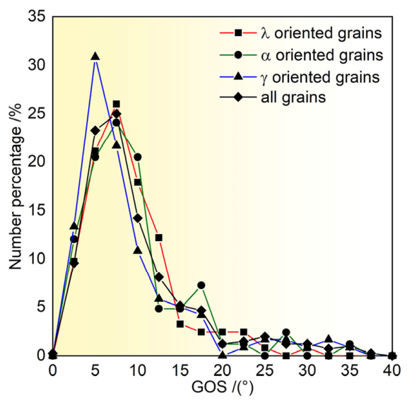
The statistical distribution of grain orientation spread (GOS) for all grains within the scanned area is shown in Figure 2, with a focused comparison among grains of λ, α, and γ orientations. For classification, λ and γ orientations were defined as grains with their normal direction aligned within 15° of <001> and <111>, respectively. α orientations were defined as grains with their rolling direction within 15° of <110>. To avoid overlap, the {001}<110> component was categorized under λ orientation, and {111}<110> under γ orientation. The scanned area contained 422 grains in total, including 131 λ-oriented grains, 47 α-oriented grains, 107 γ-oriented grains, and 137 grains with other orientations, ensuring the statistical reliability of the data. The GOS values for deformed grains were predominantly distributed between 0° and 20°. Grains with γ orientation exhibited a notably narrower GOS distribution and a lower peak GOS angle compared to other orientations, indicating a smaller intragranular orientation gradient. In contrast, λ orientations displayed a broader GOS distribution and a significantly lower fraction in the low-angle range (GOS < 5°), suggesting a larger intragranular orientation gradient. The GOS distribution for α orientations was intermediate between those of γ and λ orientations.
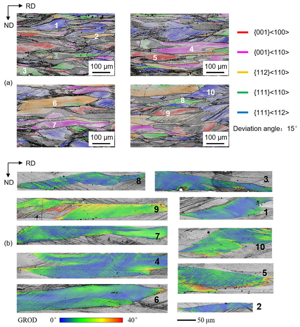
To further compare intragranular orientation gradients in different orientations, ten large deformed grains corresponding to typical cold-rolling texture components in silicon steel ({001}<100>, {001}<110>, {112}<110>, {111}<110>, and {111}<112>) were selected from the scanned area. Their corresponding GROD distributions are shown in Figure 3. After 65% cold rolling, grains 5 and 9 ({001}<100> orientation) exhibited higher GROD values, while grains 2 and 6 ({112}<110> orientation), grains 3 and 8 ({111}<110> orientation) and grains 1 and 10 ({111}<112> orientation) demonstrated relatively lower GROD. This confirms that the λ orientation are associated with higher orientation gradients than α and γ orientations. Moreover, the grain boundary regions of all ten grains presented a higher orientation gradient than the grain core. Although localized shear bands with high misorientations were observed within γ-oriented grains 8 and 10, their overall GOS remained low due to the limited number and area fraction of shear bands at a 65% rolling reduction.

3.3. Intragranular Orientation Gradients in Grain Cores and Grain Boundary Regions

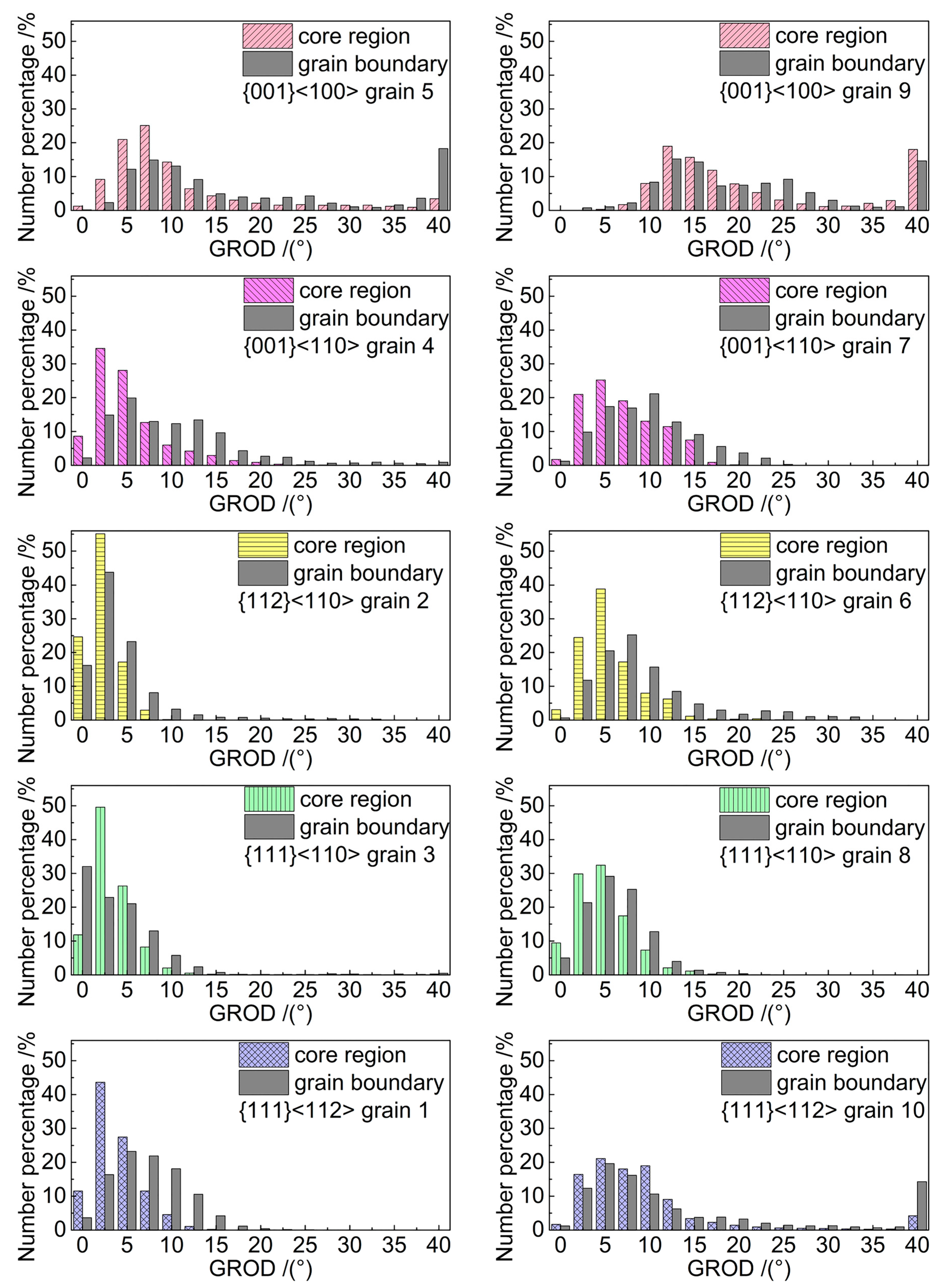
Plastic deformation near grain boundaries is influenced by interactions between adjacent grains, often resulting in distinct local orientations and orientation gradients compared to grain cores. To quantify this difference, Figure 4 separately evaluates the GROD values for the grain core and boundary regions in the ten marked grains. For deformed grains with the {001}<100> orientation (grains 5 and 9), GROD values in both core and boundary regions were broadly distributed from 0° to 40°. The boundary regions exhibited a slightly higher proportion of high-angle GROD values. In contrast, for grains with {112}<110>, {111}<110>, and {111}<112> orientations, GROD values in the core regions were concentrated primarily within 0–10°. The GROD distributions in their boundary regions were more diffuse, extending up to 25°. These results suggest that orientation rotation was relatively homogeneous in the grain cores of α- and γ-oriented grains, while the grain boundary regions experienced more heterogeneous rotation due to intergranular constraints. Consequently, λ-oriented grains maintained high orientation gradients even in their core regions, with a moderate increase near the boundaries. For α- and γ-oriented grains, orientation gradients were low in the cores, but these gradients became significantly elevated in the boundary regions.

4. Discussion

4.1. Dependence of Orientation Gradients in Grain Cores on Initial Orientation

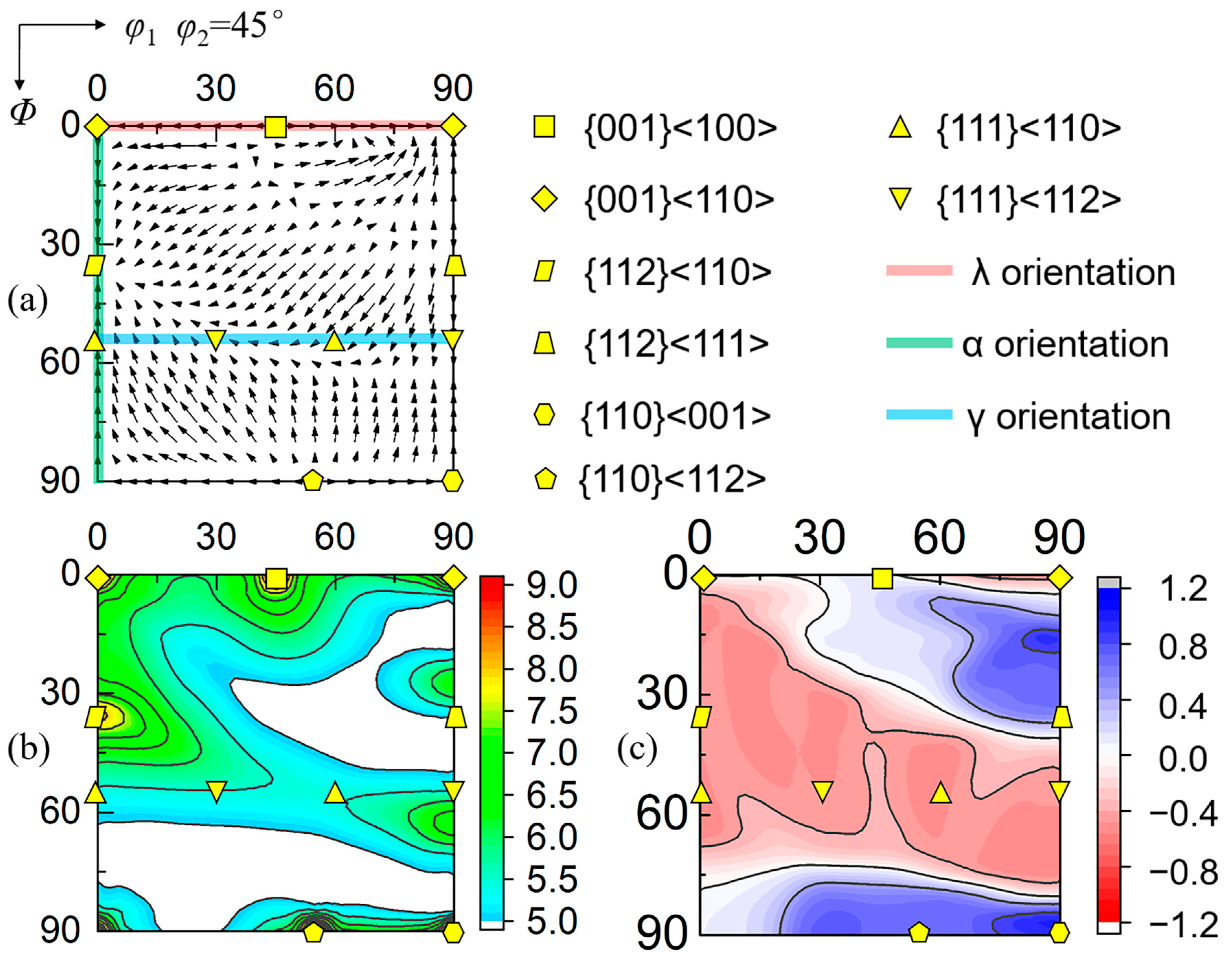
Intragranular orientation gradients are closely related to the orientation stability. The concepts of the orientation stability parameter S and the divergence of the rotation velocity field, divṘ [42,43], were employed in the present study. As defined in Equations (12)–(14), a high S value indicates strong resistance to rotation. A negative divṘ signifies that surrounding orientations in Euler space converge toward the reference orientation. Conversely, a positive divṘ indicates that the initial orientation is divergent.
S = l n 1 / R ˙
R ˙ = φ ˙ 1 2 + Φ ˙ 2 + φ ˙ 2 2 + 2 φ ˙ 1 φ ˙ 2 cos Φ
div R   ˙ = φ ˙ 1 / φ 1 + Φ ˙ / Φ + φ ˙ 2 / φ 2 + Φ ˙ cot Φ
Grain cores, located away from grain boundaries, experience less influence from neighboring grains during plastic deformation, so orientation gradients are solely related to their own orientation stability. Applying the crystal plasticity model [40], the orientation stability of the Fe-3%Si alloy during cold rolling is shown in Figure 5. The analysis identifies α and γ fibers as stable convergent orientations, characterized by a combination of a relatively high stability parameter S and a negative divergence of the rotation velocity field (divṘ < 0). In contrast, {001}<100>, {110}<112>, and {110}<001> orientations possess high S values, but their positive divṘ values classify them as unstable divergent orientations. This implies that while the exact orientation may not rotate, any slight deviation from it will be amplified, leading to high internal misorientations.
This theoretical framework aligns perfectly with the experimental GROD data. Grains with unstable divergent λ orientations exhibited the highest GROD values, consistent with their inherent instability and divergent rotation velocity fields. {001}<100> deformation orientation typically originates from the retention of initial {001}<100> orientations during rolling. During cold rolling, the exact {001}<100> remains at this orientation, while perturbed orientations rotate away from {001}<100>. As a result, grains 5 and 9 developed high orientation gradients after deformation. Even the convergent {001}<110> orientation can develop orientation gradients if the initial grain orientation was a slightly dispersed λ orientation that underwent non-uniform rotation toward this stable endpoint. Conversely, grains with stable convergent α and γ orientations maintained low GROD values in their core regions. Their high stability and negative divṘ ensure that pre-existing orientation perturbations are homogenized during deformation, effectively suppressing large orientation gradients.

4.2. Influence of Neighboring Grains on Orientation Gradients in Boundary Regions

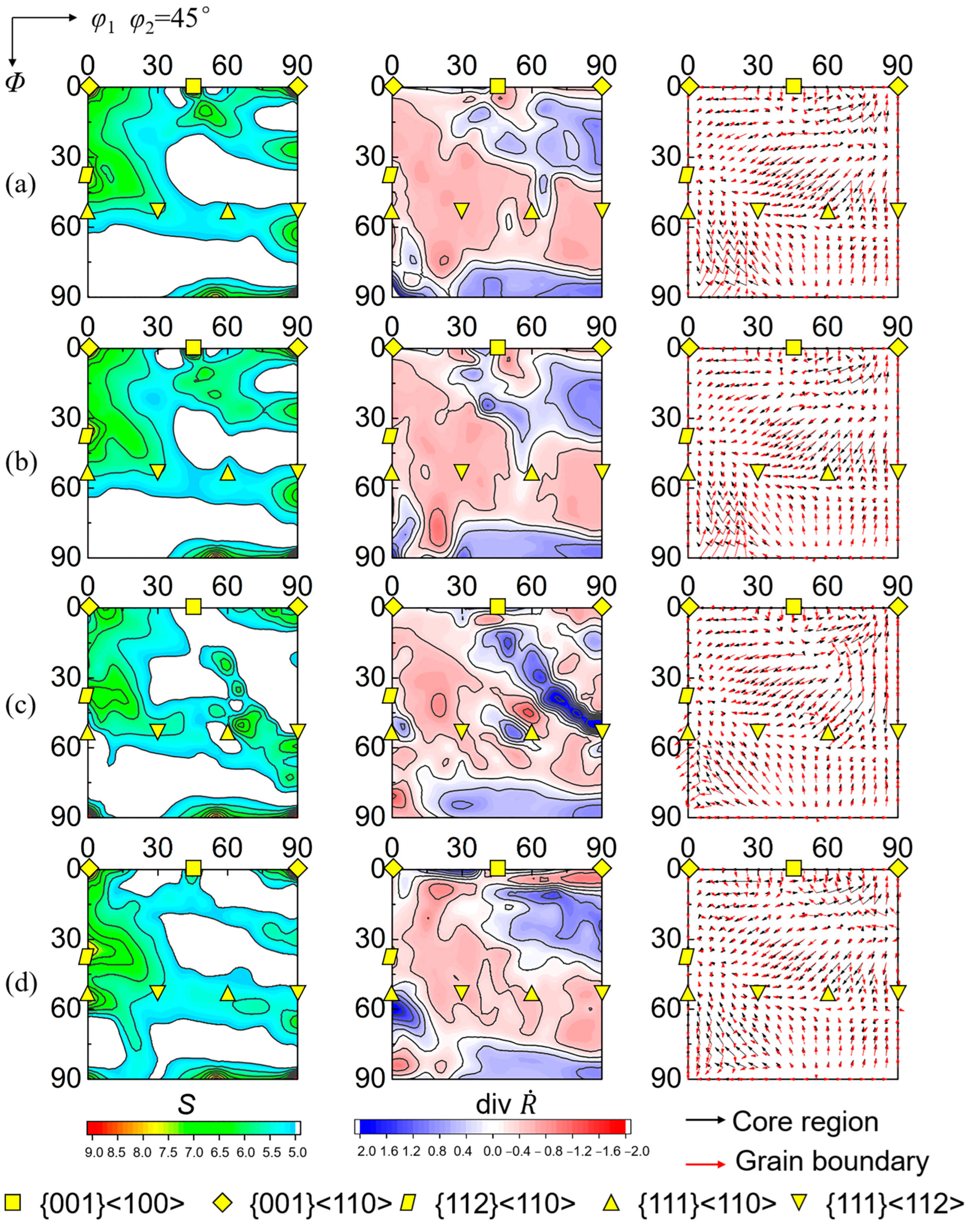
The deformation of grain boundary regions is constrained by compatibility requirements with adjacent grains, which can locally alter orientation stability. To model this effect, the crystal plasticity framework [41] was modified to incorporate the resistance to slip system activation imposed by specific neighboring orientations. Two α orientations (φ1 = 0°, Φ = 10°, φ2 = 45° and φ1 = 0°, Φ = 20°, φ2 = 45°) and two γ orientations (φ1 = 30°, Φ = 55°, φ2 = 45° and φ1 = 60°, Φ = 55°, φ2 = 45°) were selected as representative adjacent orientations to study the orientation gradients in grain boundary regions.
Figure 6 illustrates the distribution of orientation stability and the rotation velocity field in grain boundary regions under the influence of neighboring orientations. When grain boundaries are adjacent to α-oriented grains, the stability parameter S decreases for the {001}<100> and {112}<110> orientations. More notably, within the grain boundary regions, initial orientations in the range (φ1 = 10–30°, Φ = 45–85°, φ2 = 45°) shift their rotation direction from low φ1 in grain cores to high φ1, while the convergence rate toward the γ fiber for orientations in the range (φ1 = 70–90°, Φ = 45–70°, φ2 = 45°) is reduced. Consequently, the convergent behavior (divṘ) of {112}<110> and {111}<uvw> orientations is weakened. Similarly, adjacency to γ-oriented grains lowers the S value and reduces the convergence strength of these five orientations in the grain boundary regions.
These simulations provide a mechanistic explanation for the distinct GROD distributions observed between core and boundary regions in Figure 4. For inherently unstable λ-oriented grains, orientation gradients are already high in the grain core due to divergent rotation. The additional constraint from neighbors only marginally increases the gradient in the boundary region. In contrast, for stable convergent α- and γ-oriented grains, the core regions deform homogeneously with low GROD. However, the grain boundary regions, where the local stability is compromised by neighboring grains, experience heterogeneous deformation, leading to orientation gradients significantly higher than those in the grain cores. By integrating crystal plasticity modeling with detailed EBSD analysis, this study provides a predictive framework that links specific texture components to their characteristic deformation heterogeneity. This understanding offers a theoretical basis for tailoring deformation microstructures in silicon steel.

5. Conclusions

(1)
The development of orientation gradients exhibits a strong dependence on grain orientation, governed by its stability during plastic deformation. Grains with unstable divergent λ orientations develop pronounced orientation gradients. In contrast, grains with stable convergent α and γ orientations maintain highly uniform deformation, resulting in minimal orientation gradients.
(2)
Significant spatial heterogeneity in deformation exists between grain cores and boundary regions. For unstable λ orientations, orientation gradients are already high in the core, and the additional constraint from neighboring grains only causes a moderate increase at the boundaries. Conversely, for stable convergent α and γ orientations, intergranular interactions substantially reduce local orientation stability. This leads to orientation gradients in the boundary regions that are significantly higher than those in the grain cores.

Author Contributions

X.C. contributed to conceptualization, methodology, investigation, formal analysis, writing, and funding. G.Z. contributed to review, editing, resources, and funding. S.C. contributed to methodology, investigation, and validation. Y.S. contributed to conceptualization, resources, and supervision. F.Z. contributed to software, writing—review and editing, resources, and supervision. All authors have read and agreed to the published version of the manuscript.

Funding

This work was financially supported by the Doctoral Scientific Research Start-up Fund Program of Liaoning Province, China (No. 2024-BS-190); the Basic Scientific Research Project of Department of Education of Liaoning Province, China (No. JYTQN2023106); and the Special Fund for Fundamental Research Founds for Provincial Universities in Liaoning Province, China (Nos. LJBKY2024012, LJBKY2025015, LJBKY2024032, LJBKY2025014, LJ212510152036).

Data Availability Statement

The original contributions presented in this study are included in the article. Further inquiries can be directed to the corresponding author.

Conflicts of Interest

Author Songtao Chang was employed by the company Baotai Group Co., Ltd. The remaining authors declare that the research was conducted in the absence of any commercial or financial relationships that could be construed as a potential conflict of interest.

Abbreviations

The following abbreviations are used in this manuscript:
EBSDElectron backscatter diffraction
GNDsGeometrically necessary dislocations
RDRolling direction
NDNormal direction
GRODGrain reference orientation deviation
GOSGrain orientation spread
KAMKernel average misorientation
CPFEMCrystal plasticity finite element method
OIMOrientation image maps
ODFOrientation distribution function

References

  1. Futazuka, T.; Arai, M.; Seki, T.; Matsubara, R.; Morishige, N.; Ikuhara, Y.; Shibata, N. Atomic-scale observation of Σ5{310} and Σ9{411} grain boundaries in silicon steel. J. Mater. Sci. 2025, 60, 42. [Google Scholar] [CrossRef]
  2. Wang, J.H.; Yang, P.; Mao, W.M. Retention and evolution of texture in an electrical steel under vacuum annealing. J. Mater. Sci. 2017, 52, 5462–5473. [Google Scholar] [CrossRef]
  3. Pei, S.; Mei, R.B.; Bao, L.; Chen, L.H.; Li, G.L.; Liu, X.H. Tensile deformation behavior and constitutive modeling of cold-rolled non-oriented silicon steel with 2.5 wt% Si. J. Mater. Sci. 2025, 60, 2607–2622. [Google Scholar] [CrossRef]
  4. Zhang, F.; Yan, F.; Ren, J.; Zhang, M.; Sha, Y.H.; Zuo, L. Recrystallization texture evolution in non-grain oriented silicon steel via electrical current rapid heating. Mater. Charact. 2025, 227, 115333. [Google Scholar] [CrossRef]
  5. Jahangiri, M.R.; Bayani, H.; Ardestzani, M.; Mehdizadeh, M. Core loss reduction in grain oriented silicon steel sheets by two-sided laser scribing in the presence of a magnetic field. J. Alloys Compd. 2021, 891, 162080. [Google Scholar] [CrossRef]
  6. Fu, B.; Xiang, L.; Qiao, J.L.; Wang, H.J.; Liu, J.; Qiu, S.T. Primary recrystallization behaviors of Hi-B steel with lower initial nitrogen produced by the thin slab casting and rolling process. Metals 2021, 11, 189. [Google Scholar] [CrossRef]
  7. Gao, Y.; Xu, G.; Guo, X.L.; Li, G.Q.; Wang, Y. Primary recrystallization characteristics and magnetic properties improvement of high permeability grain-oriented silicon steel by trace Cr addition. J. Magn. Magn. Mater. 2020, 507, 166849. [Google Scholar] [CrossRef]
  8. Pai, N.; Prakash, A.; Samajdar, I.; Patra, A. Study of grain boundary orientation gradients through combined experiments and strain gradient crystal plasticity modeling. Int. J. Plast. 2022, 156, 103360. [Google Scholar] [CrossRef]
  9. Pilipchuk, M.; Patil, C.; Sundararaghavan, V. Comparative analysis of plasticity-based GND density estimation methods in crystal plasticity finite element models. Comput. Mater. Sci. 2026, 266, 114567. [Google Scholar] [CrossRef]
  10. Zhang, X.; Zhao, J.F.; Kang, G.Z.; Zaiser, M. Geometrically necessary dislocations and related kinematic hardening in gradient grained materials: A nonlocal crystal plasticity study. Int. J. Plast. 2023, 163, 103553. [Google Scholar] [CrossRef]
  11. Chen, R.; Liu, G.S.; Wu, P.D.; Wang, J.; Zhang, L.; Shen, Y. Slip-discreteness-corrected strain gradient crystal plasticity (SDC-SGCP) theory. Int. J. Plast. 2024, 180, 104054. [Google Scholar] [CrossRef]
  12. Raabe, D.; Zhao, Z.; Park, S.J. Theory of orientation gradients in plastically strained crystals. Acta Mater. 2002, 50, 421–440. [Google Scholar] [CrossRef]
  13. Raabe, D.; Zhao, Z.; Mao, W. On the dependence of in-grain subdivision and deformation texture of aluminum on grain interaction. Acta Mater. 2002, 50, 4379–4394. [Google Scholar] [CrossRef]
  14. Chu, S.J.; Shen, K.Y.; Sha, Y.H.; Chen, X. Orientation dependence of strain stored energy and its effect on recrystallization texture in non-oriented silicon steel. J. Mater. Eng. 2019, 47, 147–153. [Google Scholar]
  15. Sistaninia, M.; Raninger, P.; Kreuzer, H.; Prevedel, P.; Antretter, T. Designing deformation texture in non-oriented electrical steel for enhanced magnetic properties. Int. J. Mech. Sci. 2025, 290, 110090. [Google Scholar] [CrossRef]
  16. Sha, Y.H.; Sun, C.; Zhang, F.; Patel, D.; Chen, X.; Kalidindi, S.R.; Zuo, L. Strong Cube recrystallization texture in silicon steel by twin-roll casting process. Acta Mater. 2014, 76, 106–117. [Google Scholar] [CrossRef]
  17. Jiao, H.T.; Xie, X.X.; Tang, Y.; Hu, Y.; Liu, D.J.; Zhao, L.Z. Improved texture and magnetic properties in thin-gauge strip-cast non-oriented electrical steel through matching design of hot-cold rolling. J. Mater. Res. Technol. 2023, 24, 6411–6424. [Google Scholar] [CrossRef]
  18. Quadir, M.Z.; Duggan, B.J. Deformation banding and recrystallization of α fibre components in heavily rolled IF steel. Acta Mater. 2004, 52, 4011–4021. [Google Scholar] [CrossRef]
  19. Min, K.M.; Lee, H.; Joo, H.D.; Han, H.N.; Lee, M.G. Numerical modeling of shear band effect on Goss grain recrystallization in electrical steels: Crystal plasticity finite element and phase field modeling. Int. J. Plast. 2024, 180, 104049. [Google Scholar] [CrossRef]
  20. Chen, S.H.; Zhang, F.; Sha, Y.H.; Chen, X.; Zuo, L. Numerical and Experimental Investigation of Orientation Deviation in Shear Band in Grain-Oriented Silicon Steel. Materials 2025, 18, 2229. [Google Scholar] [CrossRef]
  21. Liu, Y.H.; Liu, S.F.; Fan, H.Y.; Deng, C.; Cao, L.F.; Ni, H.T.; Liu, Q. Orientation-dependent grain boundary characteristics in tantalum upon the change of strain path. Mater. Charact. 2019, 154, 277–284. [Google Scholar] [CrossRef]
  22. Li, S.C.; Guo, C.Y.; Hao, L.L.; Kang, Y.L.; An, Y.G. In-situ EBSD study of deformation behavior of 600 MPa grade dual phase steel during uniaxial tensile tests. Mater. Sci. Eng. A 2019, 759, 624–632. [Google Scholar] [CrossRef]
  23. Zaefferer, S.; Kuo, J.C.; Zhao, Z.; Winning, M.; Raabe, D. On the influence of the grain boundary misorientation on the plastic deformation of aluminum bicrystals. Acta Mater. 2003, 51, 4719–4735. [Google Scholar] [CrossRef]
  24. Mishra, S.K.; Pant, P.; Narasimhan, K.; Rollett, A.D.; Samajdar, I. On the widths of orientation gradient zones adjacent to grain boundaries. Scr. Mater. 2009, 61, 273–276. [Google Scholar] [CrossRef]
  25. Guo, Y.Z.; Li, F.D.; Suo, T.; Tang, Z.B.; Li, Y.L. A close observation on the deformation behavior of bicrystal copper under tensile loading. Mech. Mater. 2013, 62, 80–89. [Google Scholar] [CrossRef]
  26. Wright, S.I.; Suzuki, S.; Nowell, M.M. In situ EBSD observations of the evolution in crystallographic orientation with deformation. JOM 2016, 68, 2730–2736. [Google Scholar] [CrossRef]
  27. Wright, S.I.; Nowell, M.W.; Field, D.P. A review of strain analysis using electron backscatter diffraction. Microsc. Microanal. 2011, 17, 316–329. [Google Scholar] [CrossRef]
  28. Signorelli, J.W.; Roatta, A.; De Vincentis, N.S.; Schwindt, C.; Avalos, M.; Bolmaro, R.E.; Bozzolo, N. Electron backscatter diffraction study of orientation gradients at the grain boundaries of a polycrystalline steel sheet deformed along different loading paths. J. Appl. Crystallogr. 2017, 50, 1179–1191. [Google Scholar] [CrossRef]
  29. De Vincentis, N.S.; Roatta, A.; Bolmaro, R.E.; Signorelli, J.W. EBSD analysis of orientation gradients developed near grain boundaries. Mater. Res. 2019, 22, e20180412. [Google Scholar] [CrossRef]
  30. Luo, Y.L.; Ding, H.C.; Miao, L.Y.; Zhang, C.; Zhang, L.W.; Liu, H.T.; Yue, C.X. Crystal plasticity simulation of the Goss grain evolution dominated by neighboring grain orientations and in-grain orientation perturbation in grain-oriented silicon steel during cold rolling. JOM 2026, 78, 3439–3456. [Google Scholar] [CrossRef]
  31. Lim, H.; Lee, M.G.; Kim, J.H.; Adams, B.L.; Wagoner, R.H. Simulation of polycrystal deformation with grain and grain boundary effects. Int. J. Plast. 2011, 27, 1328–1354. [Google Scholar] [CrossRef]
  32. Chakraborty, S.; Hunter, A.; Luscher, D.J. Modeling inter- and intra-granular dislocation transport using crystal plasticity. Int. J. Plast. 2025, 185, 104222. [Google Scholar] [CrossRef]
  33. Zhang, K.; Liu, X.B.; Zhu, L. Characterization of geometrically necessary dislocation and deformation behavior analysis during creep of P91 steel. Eur. J. Mech. Solids 2025, 113, 105711. [Google Scholar] [CrossRef]
  34. Riyad, I.A.; Knezevic, M. A new strain gradient viscoplastic self-consistent crystal plasticity model for predicting geometrically necessary dislocations and length-scale dependent mechanical response. Int. J. Eng. Sci. 2025, 217, 104396. [Google Scholar] [CrossRef]
  35. Feng, Z.X.; Knezevic, M. Strain-gradient elasto-plastic self-consistent crystal plasticity: Applications to predicting the evolution of geometrically necessary dislocations and size sensitive mechanical response. Acta Mater. 2025, 291, 121001. [Google Scholar] [CrossRef]
  36. Kardani, A.; Montazeri, A.; Urbassek, H.M. Unraveling the temperature-dependent plastic deformation mechanisms of polycrystalline Ta implants through numerical analysis of grain boundary dynamics. J. Mater. Sci. 2022, 57, 16490–16506. [Google Scholar] [CrossRef]
  37. Malti, A.; Rashidfar, P.; Kardani, A.; Montazeri, A. Microstructural evolution and phase transitions in porous Ta/Cu alloys under high strain rates. Sci. Rep. 2025, 15, 19291. [Google Scholar] [CrossRef]
  38. Zhang, Y.; Chang, Q.; Shao, Y.W.; Guo, X.G. Assessment of the creep damage in HR3C steel using the misorientation parameters derived from EBSD technique. Mater. Lett. 2024, 306, 130893. [Google Scholar] [CrossRef]
  39. Nave, M.D.; Barnett, M.R. Texture change near grain boundaries and triple points in cold-rolled interstitial-free steel. Mater. Sci. Eng. A 2004, 386, 244–253. [Google Scholar] [CrossRef]
  40. Chen, X.; Sha, Y.H.; Chang, S.T.; Zhang, F.; Zuo, L. Oriented stability and its application in texture control. Philos. Mag. 2020, 100, 3092–3107. [Google Scholar] [CrossRef]
  41. Chen, X.; Sha, Y.H.; Chen, S.H.; Zhang, F.; Zuo, L. Neighbor-affected orientation rotation in the grain boundary region. Materials 2022, 15, 1059. [Google Scholar] [CrossRef] [PubMed]
  42. Li, S. Orientation stability in equal channel angular extrusion. Part I: Face-centered cubic and body-centered cubic materials. Acta Mater. 2008, 56, 1018–1030. [Google Scholar] [CrossRef]
  43. Li, S. Orientation stability in equal channel angular extrusion. Part II: Hexagonal close-packed materials. Acta Mater. 2008, 56, 1031–1043. [Google Scholar] [CrossRef]
Figure 1. Orientation image maps and constant φ2 sections of ODF in Fe-3%Si alloy sheet before (a,b) after 65% cold rolling.
Metals 16 00584 g001
Figure 2. GOS distribution of deformed grains with various orientations in the cold-rolled Fe-3%Si alloy sheet.
Metals 16 00584 g002
Figure 3. (a) Orientation image map and (b) GROD distribution of main texture components in the cold-rolled Fe-3%Si alloy sheet. 1–10 represent ten large deformed grains corresponding to typical cold-rolling texture components in silicon steel.
Metals 16 00584 g003
Figure 4. Comparison of GROD distributions in core region and grain boundary of the cold-rolled Fe-3%Si alloy sheet.
Metals 16 00584 g004
Figure 5. (a) Rotation velocity field, (b) orientation stability distribution of S and (c) div R ˙ in grain core during cold rolling. Arrows denote the magnitude and direction of the rotation vector.
Metals 16 00584 g005
Figure 6. Orientation stability in grain boundary regions affected by (a) (φ1 = 0°, Φ = 10°, φ2 = 45°), (b) (φ1 = 0°, Φ = 20°, φ2 = 45°), (c) (φ1 = 30°, Φ = 55°, φ2 = 45°), and (d) (φ1 = 60°, Φ = 55°, φ2 = 45°) neighboring orientations during cold rolling. Arrows denote the magnitude and direction of the rotation vector.
Metals 16 00584 g006
Disclaimer/Publisher’s Note: The statements, opinions and data contained in all publications are solely those of the individual author(s) and contributor(s) and not of MDPI and/or the editor(s). MDPI and/or the editor(s) disclaim responsibility for any injury to people or property resulting from any ideas, methods, instructions or products referred to in the content.