


Abstract
Flexible honeycomb skins offer a promising route for achieving continuous shape adaptation in morphing aircraft. In practical service, however, the skin must simultaneously accommodate large in-plane deformation while maintaining sufficient out-of-plane load-bearing capacity, which poses a fundamental design challenge. To address this trade-off, this study investigates an SMA-based U-shaped honeycomb under combined tensile deformation and aerodynamic pressure. A parametric finite element model incorporating SMA superelasticity is established, and an automated Abaqus–modeFRONTIER framework is developed for multi-objective optimization under dual loading conditions. The curvature radius, parallel-segment length, and middle-beam length are selected as design variables. The optimization objectives are defined as minimizing the maximum local strain under a prescribed tensile displacement and reducing the Z-direction displacement under aerodynamic loading as an indicator of out-of-plane bending resistance. The resulting Pareto front reveals the trade-off between flexibility and load-bearing capacity, and the sensitivities of the key geometric parameters are analyzed. Compared with the initial design, a representative optimized solution reduces the maximum local strain by 58.5% and the Z-direction displacement by 61.3%. These results provide a numerical basis for the design of SMA-based flexible skins for morphing aircraft.
1. Introduction
Morphing aircraft can continuously alter the aerodynamic profile of their wings, thereby enabling improved aerodynamic matching under different flight conditions [1,2]. As a key deformable and load-bearing component of a morphing wing, the flexible skin must satisfy two inherently conflicting requirements. On the one hand, it should possess high in-plane compliance to accommodate large tensile deformation. On the other hand, it must retain sufficient out-of-plane stiffness to resist local collapse and instability under aerodynamic loading [3,4]. Conventional homogeneous materials usually cannot reconcile these contradictory demands, which has driven growing interest in mechanical metamaterials with tailorable responses.
Among the various metamaterial topologies, zero-Poisson’s-ratio (ZPR) honeycomb structures have attracted extensive attention because of their distinctive deformation-decoupling capability [5,6,7,8]. Common ZPR configurations, such as accordion, re-entrant, and U-shaped honeycombs, can maintain negligible transverse deformation under uniaxial in-plane tension and are therefore highly attractive for preserving aerodynamic shape during morphing [9,10]. Nevertheless, although ZPR topologies provide an appropriate geometric basis for flexible skins, the low recoverable strain of conventional substrate materials, such as polymers and ordinary metals, still limits their practical large-deformation capacity [11,12].
To overcome the intrinsic limitations of conventional base materials, shape memory alloys (SMAs) have emerged as promising candidates for flexible honeycomb skins because of their outstanding superelasticity [13,14,15,16]. Compared with traditional metallic materials, SMAs exhibit a much higher recoverable strain limit and can achieve complete deformation recovery through stress-induced martensitic phase transformation [17,18,19,20]. Incorporating SMAs into ZPR honeycomb structures not only retains the topology-enabled shape-preserving behavior but also significantly enlarges the deformation range and enhances structural load-bearing capability through the material’s superelastic response [21,22,23].
Although ZPR metamaterials are theoretically well suited for large deformation, their practical application in aerospace flexible skins remains challenging [24,25,26]. Existing studies have largely focused on topology design under single loading conditions, which makes it difficult to satisfy the dual requirements of large deformability and high load-bearing capacity simultaneously. Once SMA materials are introduced, the coupling between phase-transformation nonlinearity and geometric nonlinearity further complicates the design process, rendering traditional trial-and-error strategies inefficient for performance customization within a large design space. Chang et al. [27] developed a petal-shaped zero-Poisson’s-ratio honeycomb with tunable bidirectional mechanical properties and further established an efficient automated inverse design framework by integrating an artificial neural network (ANN). Lu et al. [10] proposed a novel symmetry-asymmetric re-entrant (SARE) honeycomb by introducing symmetry-broken subcells, which effectively overcame the intrinsic trade-off in conventional honeycomb structures, where stiffness enhancement is typically achieved at the expense of auxetic performance. Inspired by the locomotion mechanism of jellyfish, Wang et al. [28] designed a biomimetic zero-Poisson’s-ratio structure based on CF/PEEK composites, achieving up to 100% recoverable large deformation together with excellent shape-recovery capability. Chang et al. [29] also established a data-driven model combining a back-propagation (BP) neural network with a genetic algorithm (GA), enabling an efficient and accurate mapping from target zero-Poisson’s-ratio properties to complex microstructural parameters.
Nevertheless, existing studies on ZPR honeycombs have mainly focused on topology development and mechanical characterization under single loading conditions, while studies on SMA-based flexible skins have primarily emphasized the benefits of superelastic materials for large recoverable deformation. In addition, recent optimization and inverse-design studies have improved the design efficiency of honeycomb structures, but they have mostly been developed for conventional cellular materials or simplified target properties. As a result, systematic multi-objective optimization studies that simultaneously consider both in-plane tensile deformation and out-of-plane load-bearing performance for SMA-based honeycomb structures remain scarce, which substantially limits their application potential under complex service conditions [30,31].
To address this gap, the present study investigates an SMA-based U-shaped honeycomb as a representative ZPR topology for flexible morphing skins and tailors its mechanical response through a multi-objective optimization strategy. A parametric geometric model and a finite element model incorporating SMA superelasticity are first established. An automated co-simulation platform driven by Python3.13 scripts is then developed by coupling Abaqus6.14 with modeFRONTIER. Under the combined requirements of in-plane stretching and out-of-plane loading, the MOGA-II algorithm is employed to quantify and optimize the trade-off between maximum structural strain and out-of-plane bending resistance. Finally, the Pareto-optimal solution set and parameter sensitivity are analyzed, and three representative design schemes are comparatively discussed to provide a numerical basis for the design of flexible morphing skins.
2. Structural Design and Parametric Analysis
2.1. Structural Design of the U-Shaped Honeycomb
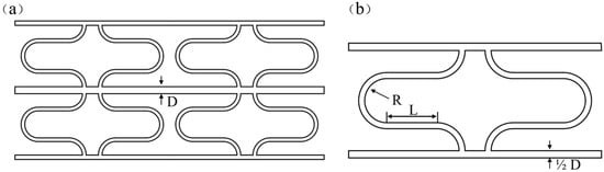
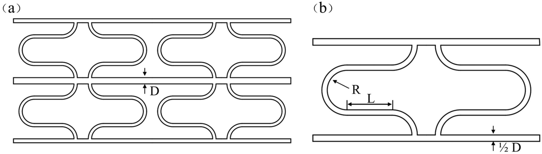
As shown in Figure 1, the analyzed geometry is a finite 2 × 2 honeycomb array constructed by repeating the U-shaped unit cell. To satisfy the requirements of zero-Poisson’s-ratio behavior and large deformability in flexible skins, a U-shaped honeycomb topology based on curved ligaments is selected for optimization [32]. In this configuration, the conventional inclined ligaments are replaced by U-shaped members with prescribed curvature, allowing the structure to deform primarily through progressive flattening of the curved segments during in-plane tension [30,33,34].
Figure 1.
Geometry of the U-shaped honeycomb: (a) Overall Structure; (b) unit cell.
Among various ZPR topologies, the U-shaped honeycomb is selected because its curved-ligament geometry is well suited to flexible morphing skins. Under in-plane tension, the structure deforms mainly through progressive flattening of the curved segments, which is beneficial for accommodating large deformation while maintaining the ZPR characteristic. In addition, its geometry can be conveniently parameterized by R, L, and D, which makes it suitable for the present multi-objective optimization of flexibility and out-of-plane load-bearing capacity.
Figure 1 shows the overall configuration and the geometric definition of the U-shaped honeycomb unit cell. To improve clarity, all characteristic dimensions are labeled consistently in the figure. The unit-cell geometry is parameterized by three main variables: the curvature radius R, the parallel-segment length L, and the middle-beam length D. Here, R defines the curvature of the U-shaped transition region, L denotes the length of the two parallel straight segments, and D represents the longitudinal length of the middle connecting beam between the two curved segments. These three parameters were selected as the design variables in the subsequent optimization because they directly control the geometric deformation mode of the cell as well as the trade-off between in-plane flexibility and out-of-plane load-bearing capacity. The wall thickness was fixed at t = 2 mm and was not treated as a design variable in the present optimization. Other geometric quantities shown in Figure 1 are kept constant throughout the study unless otherwise specified.
2.2. Constitutive Model of the Shape Memory Alloy
The SMA substrate was used to exploit its superelastic response under large recoverable deformation. Since the mechanical behavior of SMAs is governed by stress-induced phase transformation between austenite and martensite, a nonlinear constitutive description is required in the finite element analysis. In this study, the built-in superelastic constitutive model available in Abaqus was adopted to represent the material behavior of the SMA [35].
Under the isothermal condition considered in this study, the total strain can be decomposed into elastic strain and transformation strain.
where is the total strain, is the elastic strain, and is the transformation strain associated with the stress-induced phase transformation.
The superelastic response of the SMA is characterized by the elastic moduli of the austenite and martensite phases, and , the Poisson’s ratio , the maximum transformation strain , and the critical stresses for forward and reverse transformation. Specifically, and denote the start and finish stresses of the forward transformation from austenite to martensite, whereas and denote the start and finish stresses of the reverse transformation during unloading. The material parameters used in the simulations are listed in Table 1, where and are given in MPa, is dimensionless, and the transformation stresses are also given in MPa.
Table 1.
Material properties of the SMA used in the simulation.
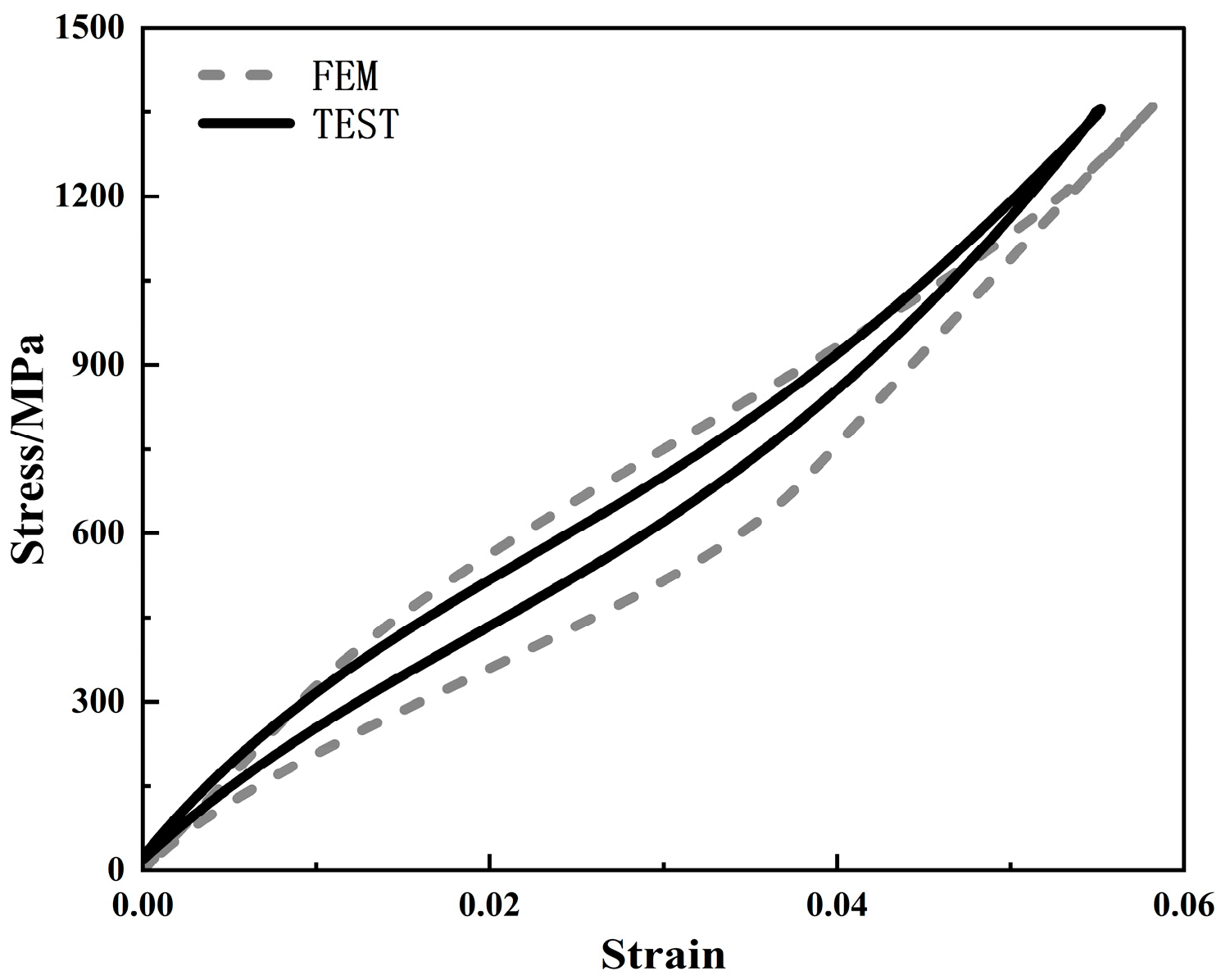
In the present study, this constitutive model was used together with geometric nonlinearity in Abaqus to simulate the superelastic response of the SMA-based U-shaped honeycomb under tensile deformation and aerodynamic loading. The material definition was implemented using the built-in superelastic SMA formulation in Abaqus rather than a user-defined material subroutine. Accordingly, this subsection is intended to clarify the constitutive description, the main assumptions adopted in the simulation, and the material parameters used in the finite element model.The stress-strain curve is presented in Figure 2.
Figure 2.
Superelastic stress–strain response of the SMA.
2.3. Boundary Conditions and Loading Cases
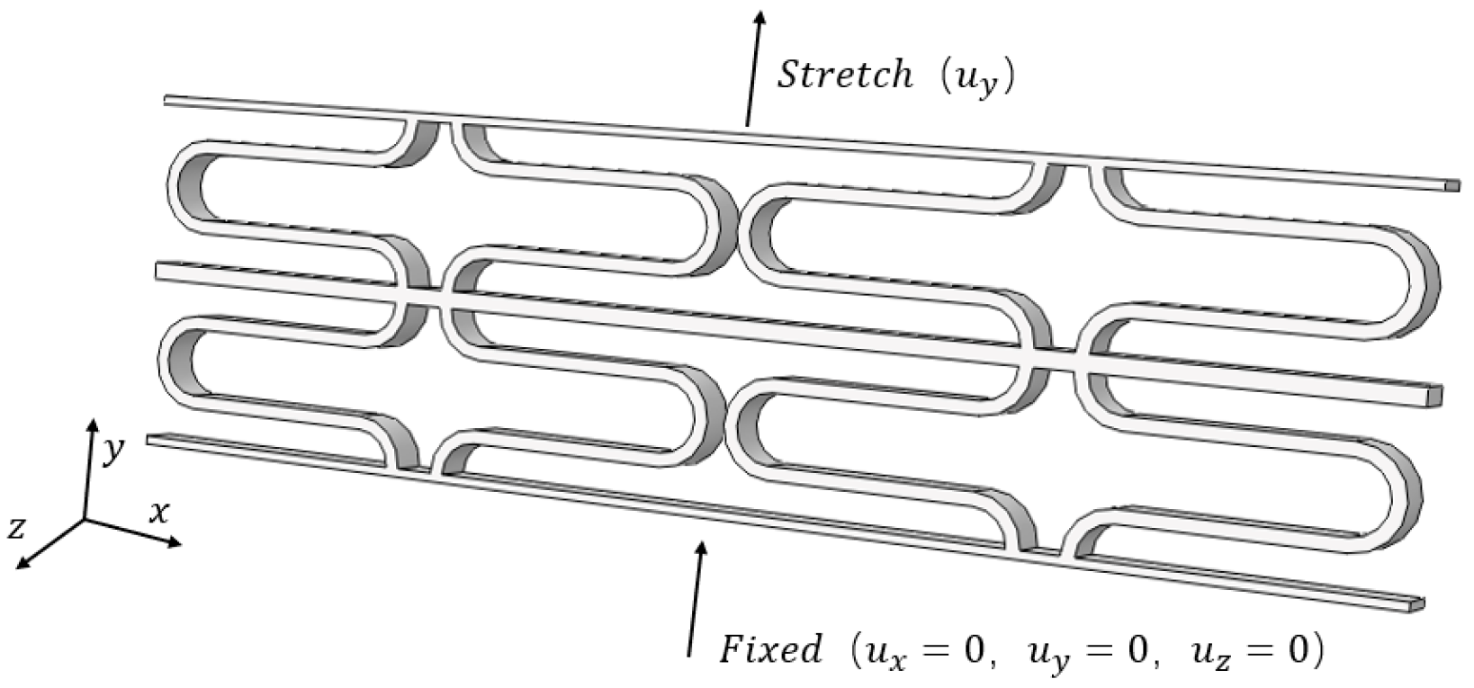
In the present study, the finite 2 × 2 honeycomb array is treated as a representative local segment of a morphing skin integrated into an aircraft wing, rather than as a full wing-scale structural model. Boundary conditions and external loads are applied directly to the finite array so that the responses of the edge cells are explicitly included rather than idealized through periodic boundary conditions. This simplified model is intended to capture the two primary mechanical requirements of the flexible skin in service, namely in-plane extensibility during wing morphing and out-of-plane load-bearing capacity under aerodynamic loading. Accordingly, separate analysis steps are established for these dual operating conditions. For the tensile loading case, which represents the deformation demand induced by wing morphing, all degrees of freedom at the bottom boundary are fixed, while a prescribed displacement is applied along the loading direction at the top boundary. This loading step is used to evaluate the maximum local strain of the honeycomb under a specified deformation level.The boundary conditions are shown in Figure 3.
Figure 3.
Boundary conditions under tensile loading.
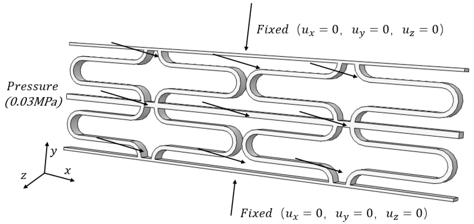
For the aerodynamic loading case, a uniformly distributed normal pressure is applied to the upper surface of the structure to characterize the out-of-plane bending response. The resulting displacement in the thickness direction is used to assess the out-of-plane bending stiffness of the flexible skin.The boundary conditions are shown in Figure 4.
Figure 4.
Boundary conditions under aerodynamic pressure.
2.4. Parametric Modeling
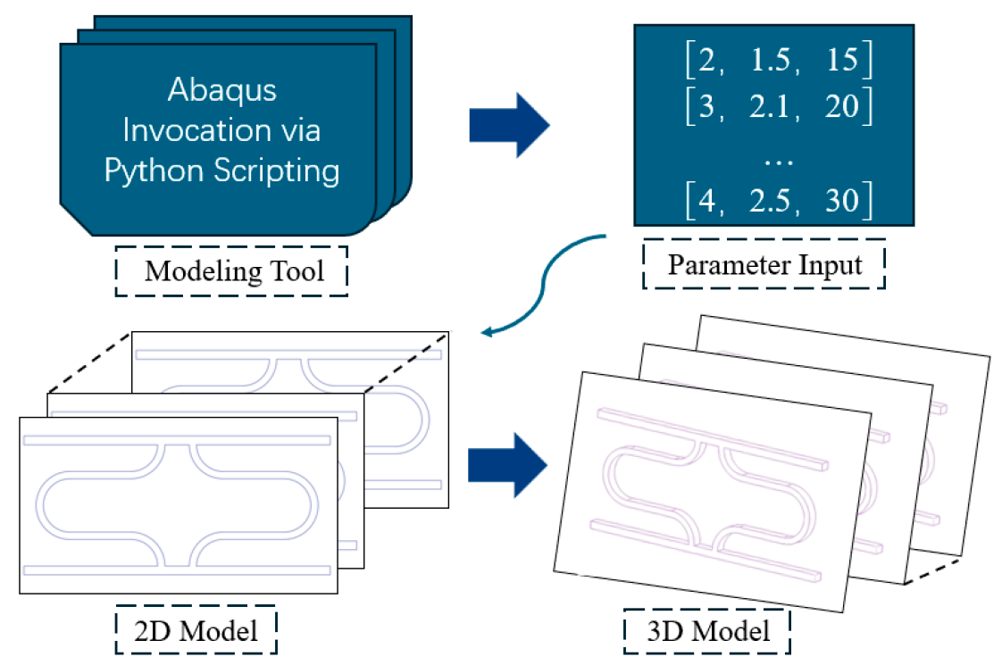
Multi-objective optimization requires a large number of iterations and sample evaluations. To improve computational efficiency, a Python-driven parametric modeling procedure was established. In this workflow, the geometric parameters of the U-shaped honeycomb are written to external files, and Abaqus is automatically called to reconstruct the geometry, assign material properties, generate the mesh, apply boundary conditions, and submit analysis jobs. This automated procedure provides the computational basis for the subsequent co-simulation and multi-objective optimization.The detailed procedure is depicted in Figure 5.
The finite element simulations were performed in Abaqus using a 3D model of the finite honeycomb array. The structure was discretized with C3D8R elements. A global seed size of 0.25 was used for meshing. During the optimization process, the same element type and meshing strategy were adopted for all configurations. Because the geometry was updated automatically during the parametric optimization, the exact number of elements could vary slightly among different configurations after remeshing.
Figure 5.
Workflow of the automated co-simulation framework.
3. Multi-Objective Optimization Algorithms
3.1. Establishment of the Co-Simulation Platform
To improve the efficiency of structural optimization for complex nonlinear problems, a fully automated co-simulation platform integrating Abaqus and modeFRONTIER was established. In this platform, Python scripts were used to enable data exchange and workflow control between the finite element solver and the optimization software, thereby forming an automated optimization loop. The specific process is shown in Figure 6.
Figure 6.
Workflow of the multi-objective co-simulation and optimization framework.
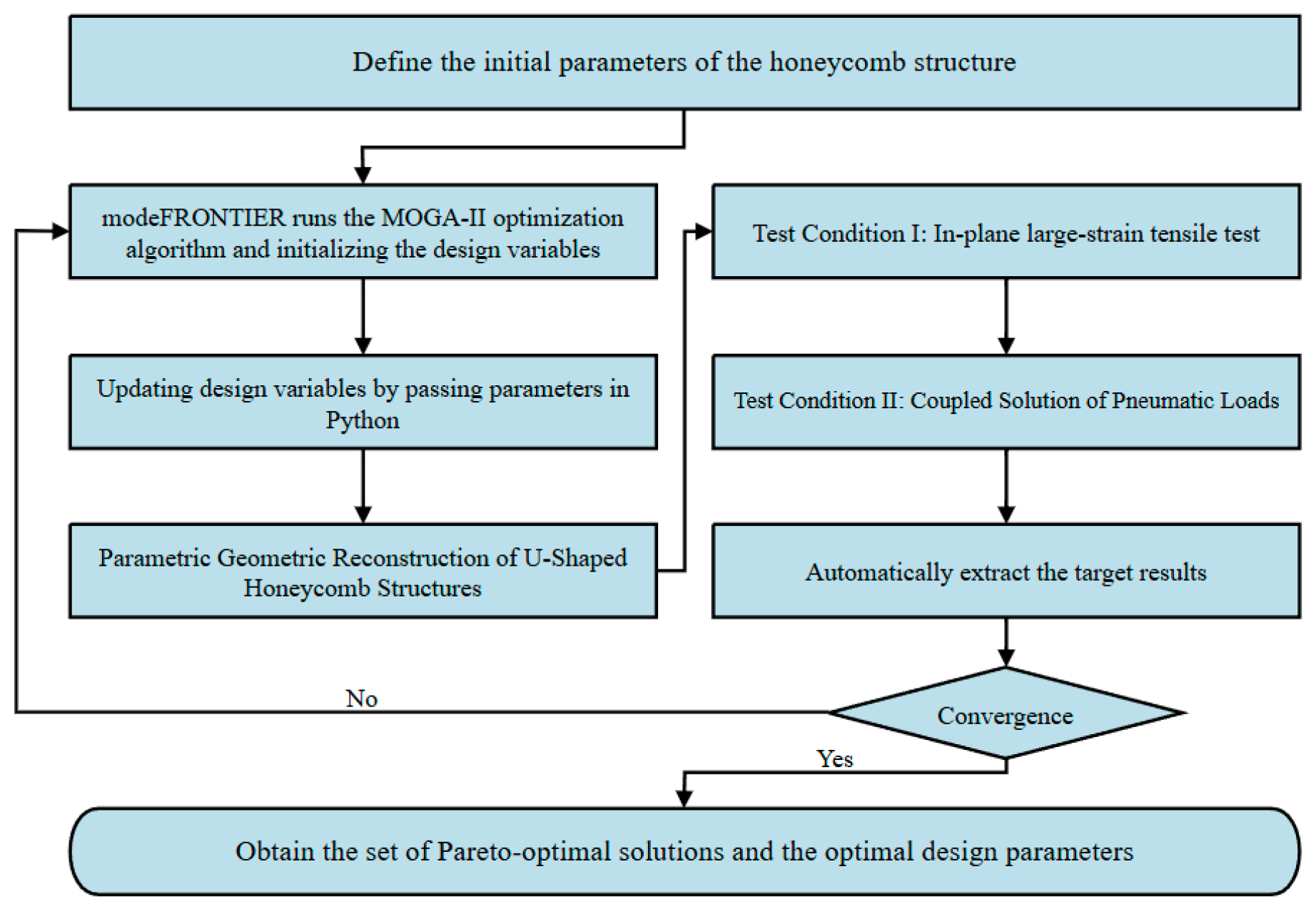
Abaqus was employed to perform the structural simulations and solve the nonlinear response of the SMA-based U-shaped honeycomb under dual loading conditions. Through the Abaqus Python API, the geometric parameters were updated automatically, and the simulation jobs were submitted iteratively. After each analysis, key response quantities, including the maximum structural strain and the Z-direction displacement, were extracted and stored automatically. modeFRONTIER served as the optimization driver and executed the global search process using the built-in MOGA-II algorithm. Based on the extracted response data, new design variables were generated and passed back to the Python script, thus establishing a closed-loop workflow for automated co-simulation and multi-objective optimization.
3.2. Selection of the Optimization Algorithm
The design of flexible skins involves two conflicting requirements, namely large deformability and high out-of-plane load-bearing capacity, which can be formulated as a multi-objective optimization problem. In the present study, MOGA-II was adopted because it is suitable for nonlinear problems with competing objectives and can provide a diverse set of Pareto-optimal solutions in a single optimization run. In addition, the structural response of the SMA-based U-shaped honeycomb is governed by both material and geometric nonlinearities, which makes gradient-based methods less suitable for the present optimization problem. MOGA-II was implemented through the built-in optimization module in modeFRONTIER.
The population size was set to 20, and the maximum number of generations was set to 25. These settings were selected empirically as a compromise between optimization efficiency and computational cost, because each design evaluation requires nonlinear finite element simulations under dual loading conditions. An elitist strategy was employed to preserve the best solutions during the evolutionary process. Although a systematic parameter-tuning study was not carried out in the present work, the adopted settings were considered sufficient to obtain a representative Pareto solution set for the current design problem.
3.3. Definition of the Optimization Model
The optimization problem was formulated based on the geometric characteristics of the U-shaped honeycomb and their influence on mechanical performance. The curvature radius R, the parallel-segment length L, and the middle-beam length D were selected as the design variables. Their ranges were defined as:
where R, L, and D are all given in mm.
Considering the dual requirements of in-plane tensile deformation and out-of-plane aerodynamic loading, two competing objective functions were defined. The first objective was to minimize the maximum structural strain under the prescribed tensile displacement, namely
where is the maximum local strain in the honeycomb and is dimensionless. The second objective was to minimize the Z-direction displacement under aerodynamic loading, namely
where is the out-of-plane displacement in the Z direction and is given in mm. Since a smaller Z-direction displacement corresponds to higher out-of-plane bending stiffness, minimizing is equivalent to improving the out-of-plane load-bearing capacity of the structure.
To ensure structural safety, a strain constraint was imposed such that
where denotes the allowable superelastic strain limit of the SMA.
Accordingly, the multi-objective optimization problem can be written in standard form as
4. Pareto Front Analysis and Discussion
This section presents a detailed analysis of the results obtained from the multi-objective optimization, including the characteristics of the Pareto front, the sensitivity of the design parameters to the optimization objectives, and the mechanical performance comparison of representative design points. The aim is to provide both theoretical insight and technical support for the structural design of flexible skins.
4.1. Pareto Front Analysis
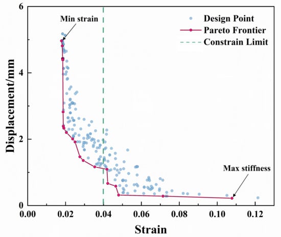
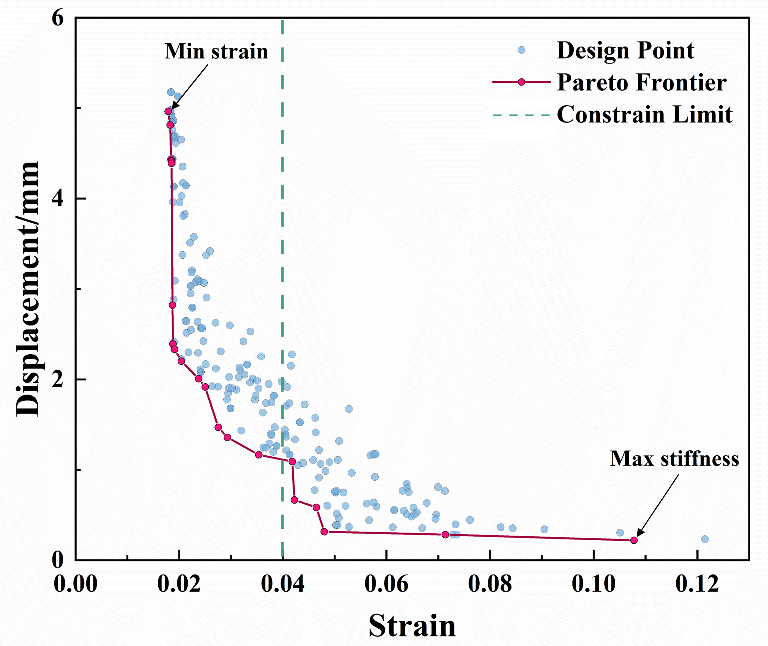
Figure 7 presents the Pareto front obtained using the MOGA-II algorithm. The horizontal axis represents the maximum structural strain under a prescribed in-plane tensile displacement, whereas the vertical axis represents the Z-direction displacement of the flexible skin under a constant aerodynamic load. In this study, the Z-direction displacement is used as an indicator of the out-of-plane load-bearing capacity of the structure, such that a smaller displacement corresponds to stronger out-of-plane load-bearing capacity. The red curve represents the Pareto front, and each point on this front corresponds to a non-dominated solution, meaning that one objective cannot be further improved without sacrificing the other. The Pareto front clearly reveals the trade-off between in-plane deformability and out-of-plane bending resistance. As the Z-direction displacement decreases, the overall structural strain tends to increase, indicating that achieving an ideal balance between large deformability and high out-of-plane load-bearing capacity remains challenging for the present U-shaped topology.
Figure 7.
Pareto front of the multi-objective optimization.
The distribution of the Pareto front further demonstrates the strong competition between out-of-plane load-bearing capacity and local in-plane strain. The upper-left region of the curve corresponds to the minimum-strain solutions, representing highly flexible designs. In this region, the local strain under tensile loading is reduced to approximately 2%, but at the cost of markedly weakened resistance to aerodynamic loading, with the Z-direction displacement increasing to nearly 5 mm. In contrast, the lower-right region corresponds to the minimum Z-direction displacement solutions. Here, the Z-direction displacement is significantly suppressed to about 0.2 mm, whereas the local structural strain increases to more than 10%, far exceeding the allowable strain range of the SMA. This result suggests that pursuing bending stiffness alone would inevitably induce severe stress concentration in the honeycomb under tensile loading.
The green dashed line in Figure 7 denotes the strain-constraint boundary of the SMA. As shown by the distribution of the design points, many solutions with low-Z-direction displacement fall into the failure region on the right side of this boundary. This indicates that, under practical service conditions, such low Z-direction displacement configurations would fail during large deformation because the local strain exceeds the allowable superelastic strain of the SMA. Therefore, the truly feasible optimal solutions must be confined to the safe design domain on the left side of the strain-constraint boundary.
Compared with the initial honeycomb design, the optimized solutions located in the lower-left region of the figure achieve a more favorable performance compromise. On the Pareto front, this improvement is manifested by an overall shift in the solution set toward a better region, namely, lower Z-direction displacement at the same level of in-plane flexibility, or greater stretchability at the same level of Z-direction displacement. These results clearly demonstrate the effectiveness of the proposed multi-objective optimization strategy in resolving the conflicting design requirements of flexible skins.
4.2. Parameter Sensitivity Analysis
To gain deeper insight into the roles of the design variables in governing the mechanical performance of the U-shaped honeycomb, a sensitivity analysis was performed on the three key geometric parameters, namely the curvature radius R, the parallel-segment length L, and the middle-beam length D. By correlating the distribution of these variables along the Pareto front with the corresponding responses of the objective functions, the individual and coupled effects of the geometric parameters on the structural behavior of the honeycomb can be systematically characterized.
4.2.1. Effect of the Parallel-Segment Length L
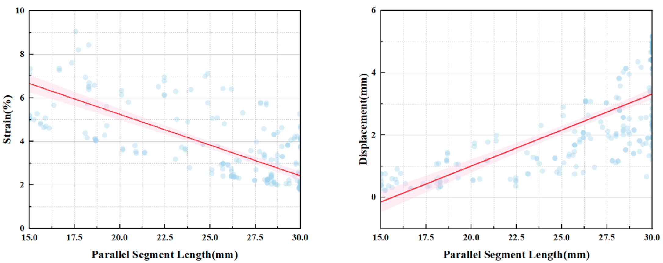
As shown in Figure 8, the parallel-segment length L has a pronounced influence on structural flexibility. As L increases, the geometric expansion space of the unit cell in the loading direction becomes larger, allowing local deformation to be redistributed over a wider region. As a result, the strain concentration in the curved and connecting regions is alleviated, leading to a reduction in the maximum structural strain. This indicates that increasing L is beneficial for improving the in-plane deformation compatibility and stretchability of the structure.
Figure 8.
Effect of the parallel-segment length L.
However, a larger L also increases the unsupported span under out-of-plane loading, making bending deformation more likely to occur. Consequently, the Z-direction displacement increases, and the out-of-plane bending stiffness decreases. Therefore, L is an important parameter affecting both flexibility and load-bearing capacity. Although a larger L helps reduce strain, it also weakens the out-of-plane stability of the structure. In practical design, its value should be selected within a reasonable range to achieve a balance between large deformability and structural stiffness.
4.2.2. Effect of the Middle-Beam Length D
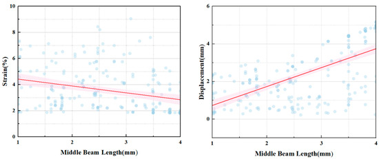
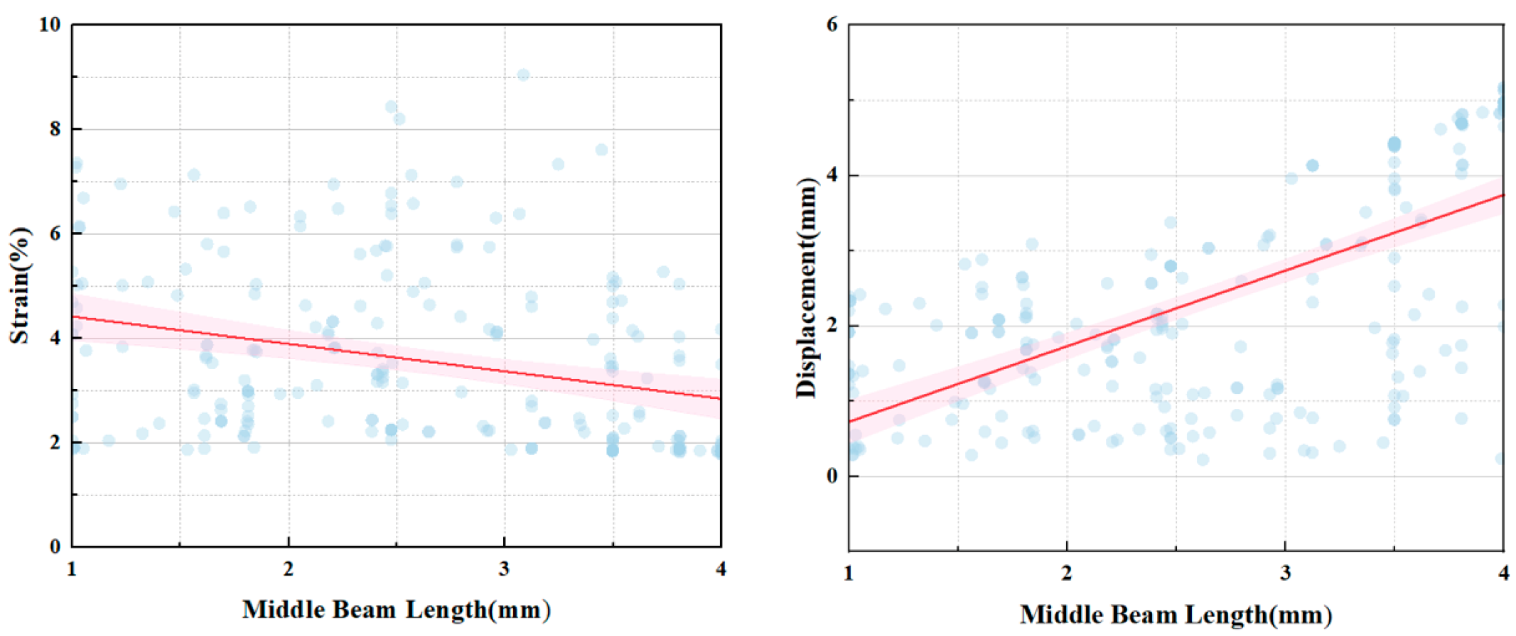
As shown in Figure 9, the middle-beam length D is a key parameter governing the overall support characteristics of the honeycomb and is particularly sensitive to the out-of-plane response. As D increases, the effective support spacing under transverse loading becomes larger, and the relative density of the structure decreases, which intensifies the out-of-plane bending deformation. As a result, the Z-direction displacement increases markedly, indicating a significant reduction in out-of-plane bending stiffness.
Figure 9.
Effect of the middle-beam length D.
Under in-plane tensile loading, increasing D can also enlarge the overall deformation coordination space of the unit cell, thereby redistributing part of the local deformation and slightly reducing the maximum strain. Nevertheless, this beneficial effect is secondary compared with its strong influence on the out-of-plane displacement. Therefore, D should primarily be regarded as a stiffness-dominant parameter. In the optimization process, its upper bound should be carefully controlled to ensure sufficient shape-retention capability of the flexible skin under aerodynamic loading.
4.2.3. Effect of the Curvature Radius R
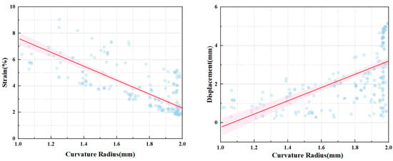
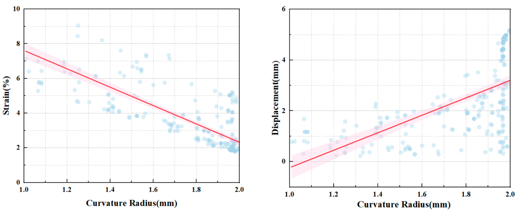
As shown in Figure 10, the curvature radius R mainly affects the local stress distribution in the transition region of the U-shaped curved beam. As R increases, the geometric transition becomes smoother, resulting in a more uniform load-transfer path and a reduction in local stress concentration. Accordingly, the maximum structural strain decreases. This suggests that R is a key parameter for suppressing local strain peaks and improving the structural safety of the honeycomb.
Figure 10.
Effect of the curvature radius R.
On the other hand, a larger R also weakens the geometric constraint provided by the curved beam to some extent, making local bending more likely to develop under out-of-plane loading and thereby increasing the Z-direction displacement. Compared with D and L, however, the influence of R on the overall out-of-plane stiffness is relatively less pronounced. Thus, R is better considered as a fine-tuning parameter for mitigating local strain concentration rather than a dominant parameter controlling the global load-bearing capacity.
4.3. Discussion
Overall, increasing L, D, or R contributes to reducing the maximum structural strain, but at the expense of a larger Z-direction displacement. This trend reflects the intrinsic trade-off between in-plane large deformability and out-of-plane load-bearing capacity in the U-shaped honeycomb. Among the three parameters, D is the most influential with respect to the out-of-plane displacement and primarily governs the global stiffness of the structure. L significantly affects both strain and displacement and therefore serves as a key parameter in regulating structural flexibility. In contrast, R mainly controls the local strain distribution and is effective in alleviating stress concentration.
Therefore, in the optimization design of the flexible skin, the out-of-plane deformation level should first be controlled by limiting D. On this basis, L can be adjusted to tune the overall deformability, while R can be further optimized to suppress local strain concentration. Such a design strategy is beneficial for achieving a rational balance between flexibility and load-bearing capacity.
4.4. Comparison of Representative Design Points
To further clarify the engineering significance of the Pareto-optimal solutions, three representative design schemes are selected for comparison: a high-stiffness design, a balanced-compromise design, and a high-flexibility design. Their corresponding geometric parameters and response values are summarized in Table 2.
Table 2.
Parameters and responses of representative design points.
According to the distribution characteristics of the Pareto front, three representative design points, namely, the high-stiffness, balanced-compromise, and high-flexibility configurations, were selected for comparative analysis to further clarify the mechanical response characteristics and engineering applicability of the U-shaped honeycomb under different parameter combinations.
The high-stiffness design point is located in a region of the Pareto front with relatively high out-of-plane bending stiffness. Such configurations generally exhibit a more compact geometric arrangement, which leads to a more efficient load-transfer path and stronger out-of-plane support. Under this design, the U-shaped honeycomb can effectively resist external aerodynamic loads and is therefore suitable for applications requiring high load-bearing capacity and strong shape-retention capability. However, owing to its relatively high overall stiffness, the in-plane deformation compatibility is reduced, and a larger actuation force is generally required to achieve large deformation.
The balanced-compromise design point is located in the region of the Pareto front and represents a favorable balance between out-of-plane bending stiffness and in-plane deformability. Its geometric characteristics are typically the result of coordinated optimization of the parallel-segment length, curvature radius, and middle-beam length. Under this design, the U-shaped honeycomb can maintain satisfactory out-of-plane load-bearing capacity while still providing sufficient tensile deformability. Therefore, it is particularly suitable for general flexible-skin applications where both stiffness and flexibility must be considered simultaneously.
The high-flexibility design point is located in the region of the Pareto front associated with superior in-plane deformability. Such configurations generally provide a larger geometric expansion space and a smoother local curvature transition, which helps reduce strain concentration and improve stretchability. Under this design, the U-shaped honeycomb exhibits high in-plane flexibility and can accommodate significant deformation, making it suitable for morphing aircraft skins with stringent deformation requirements. However, its out-of-plane bending stiffness is relatively low, and the structure is therefore more susceptible to deformation under external loading.
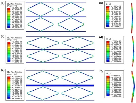
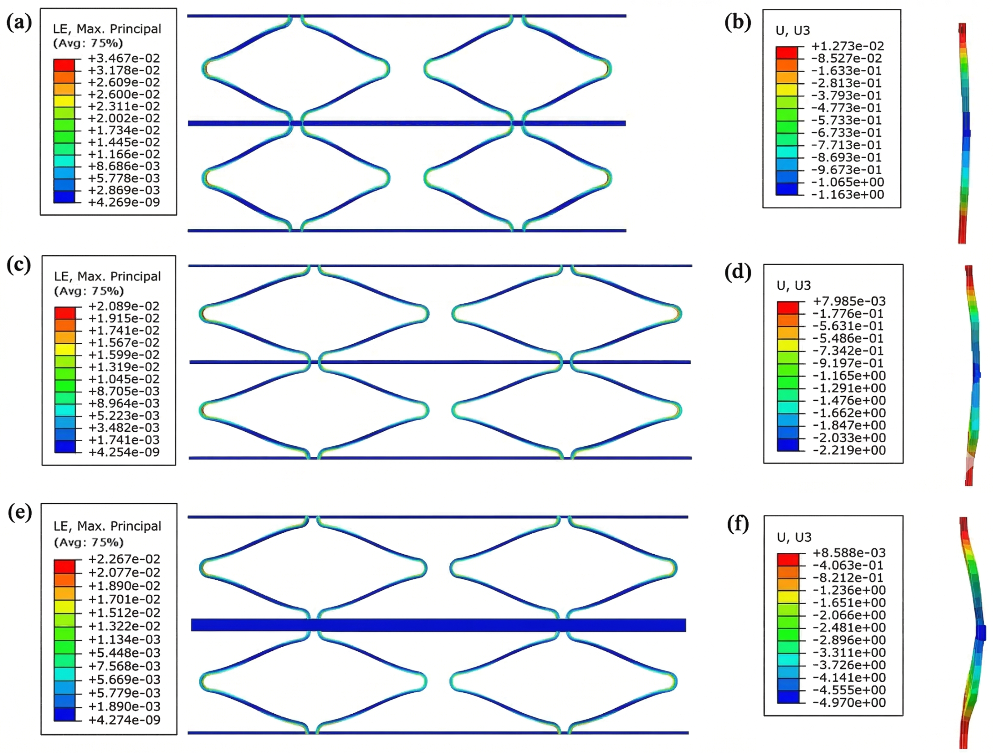
A comparison of the mechanical responses of these three representative design points provides useful guidance for parameter selection in flexible-skin structures designed for different service requirements. To verify the reliability of the multi-objective optimization results, the geometric parameters of the representative design points were extracted and re-evaluated using finite element simulations in Abaqus, as shown in Figure 11. The results indicate that, for the balanced-compromise design point located in the middle region of the Pareto front, the relative error between the finite element results and the optimization predictions is very small, demonstrating a high level of agreement. For the high-flexibility design point, the maximum strain obtained from finite element validation is 2.26%, which is slightly higher than the predicted value of 1.99%. This discrepancy can mainly be attributed to the more pronounced geometric large-deformation behavior of this configuration under tensile loading, which intensifies local nonlinear effects. The finite element simulation is able to capture such nonlinear deformation characteristics more accurately, and the resulting deviation remains within a reasonable tolerance range. These results confirm that the proposed co-simulation platform can accurately characterize the superelastic nonlinear response of the SMA-based honeycomb under complex large-deformation conditions, thereby providing a reliable theoretical basis for the optimal design of flexible skins for morphing aircraft.
Figure 11.
Simulation contour maps. (a) High-stiffness strain contour map; (b) High-stiffness displacement contour map; (c) Balanced-compromise strain contour map; (d) Balanced-compromise displace-ment contour map; (e) High-flexibility strain contour map; (f) High-flexibility displacement con-tour map.
5. Conclusions
To address the inherent conflict between large deformability and high load-bearing capacity in flexible skins for morphing aircraft, an SMA-based U-shaped honeycomb structure was proposed in this study. By establishing an automated optimization platform integrating finite element analysis and a multi-objective genetic algorithm, the mechanical performance of the structure was systematically investigated, and its parametric characteristics were analyzed. The main conclusions are summarized as follows.
- (1)
- A Python-driven co-simulation platform integrating Abaqus and modeFRONTIER was established, enabling the automated coupled solution of the SMA constitutive model and the geometric nonlinearity of the structure. This platform effectively overcame the limitations of conventional trial-and-error approaches in complex design spaces and accurately captured the Pareto-optimal front governing the trade-off between in-plane deformability and out-of-plane stiffness of the U-shaped honeycomb, thereby providing an efficient computational framework for the customized design of flexible skins.
- (2)
- The parameter sensitivity analysis clarified the roles of the key design variables in determining structural performance. The middle-beam length D was identified as the dominant parameter governing the overall mechanical response, and its increase led to an increase in Z-direction displacement and a reduction in out-of-plane load-bearing capacity. The curvature radius R was found to be the key parameter for tuning in-plane flexibility, while its influence on Z-direction displacement and overall out-of-plane load-bearing capacity was relatively limited. The parallel-segment length L effectively extended the deformation space in the loading direction, and its moderate increase further alleviated local tensile strain without excessively compromising the out-of-plane load-bearing capacity.
- (3)
- The Pareto front results demonstrated that the optimized U-shaped honeycomb significantly outperformed the initial configuration. Under the constraint of maintaining the SMA within its superelastic strain range, the balanced-compromise design achieved substantial performance enhancement under 200% large deformation. Specifically, compared with the initial design, the structural strain was reduced by 58.5% and the Z-direction displacement by 61.3%. These results indicate that the optimized configuration provides an improved balance between deformability and load-bearing capacity within the allowable superelastic strain range of the SMA.
It should be noted that the present study is primarily based on numerical simulations, and experimental validation of the optimized SMA-based U-shaped honeycomb has not yet been carried out. In addition, the loading cases considered here are simplified representations of the in-plane deformation demand and local aerodynamic pressure acting on a morphing skin, rather than full wing-scale aeroelastic service conditions. Possible manufacturing-related issues, such as fabrication accuracy, assembly tolerance, and material-processing constraints of the SMA-based honeycomb, were also not considered in the current optimization framework. In future work, experimental verification and manufacturability-oriented design will be further investigated to improve the engineering applicability of the proposed optimization strategy.
Author Contributions
Conceptualization, T.N., C.W., Z.W. and C.C.; Methodology, T.N., C.W., Z.W., C.C. and Z.X.; Software, T.N., C.W. and Z.W.; Validation, T.N. and Z.W.; Formal analysis, T.N. and C.W.; Investigation, T.N., C.W. and X.C.; Resources, T.N., C.C., X.C. and Z.X.; Data curation, T.N.; Writing—original draft, T.N. and C.W.; Writing—review & editing, T.N., C.W., Z.W., C.C., X.C. and Z.X.; Visualization, T.N., C.W. and Z.X.; Supervision, Z.W. and X.C.; Project administration, X.C. All authors have read and agreed to the published version of the manuscript.
Funding
This research received no external funding.
Data Availability Statement
The original contributions presented in this study are included in the article. Further inquiries can be directed to the corresponding author.
Conflicts of Interest
Authors Tao Niu and Chu Chu were employed by the company AVIC Manufacturing Technology Institute. The remaining authors declare that the research was conducted in the absence of any commercial or financial relationships that could be construed as a potential conflict of interest.
Abbreviations
The following abbreviations are used in this manuscript:
| SMA | Shape memory alloy |
| ZPR | Zero-Poisson’s-ratio |
| FEM | Finite element method |
| MOGA-II | Multi-Objective Genetic Algorithm II |
References
- Liu, W.; Zhang, Y.; Guo, Z.; Li, D.; Zhao, S.; Xie, W. Analyzing in-plane mechanics of a novel honeycomb structure with zero Poisson’s ratio. Thin-Walled Struct. 2023, 192, 111134. [Google Scholar] [CrossRef] [Scilit]
- Zhang, B.; Gu, J.; Pan, W.; Huang, J.; Sun, H. 4D-printed novel zero Poisson’s ratio honeycombs based on thermoplastic polymers: Thermo-mechanical experiments and modeling. Thin-Walled Struct. 2025, 215, 113486. [Google Scholar] [CrossRef] [Scilit]
- Ahmad, D.; Parancheerivilakkathil, M.S.; Kumar, A.; Goswami, M.; Ajaj, R.M.; Patra, K.; Jawaid, M.; Volokh, K.; Zweiri, Y. Recent developments of polymer-based skins for morphing wing applications. Polym. Test. 2024, 135, 108463. [Google Scholar] [CrossRef] [Scilit]
- Qi, W.; Zhang, Y.; Zhang, Y.; Yan, H.; Liu, Y.; Zhang, Z. Advanced Honeycomb Structures for Aerospace: Multiscale Mechanics, Bio-inspired Hierarchical Design, and Multi-physics Coupling Responses. Thin-Walled Struct. 2025, 114132. [Google Scholar]
- Mamoun, O.; Ajaj, R.; Zweiri, Y.; Scarpa, F. The Quadcomb: A novel zero Poisson’s ratio honeycomb structure with 2D compliance for morphing aircraft applications. Mater. Des. 2025, 257, 114512. [Google Scholar] [CrossRef] [Scilit]
- Zhou, Y.; Zhong, Y.; Tang, Y.; Liu, R. Static and Dynamic Characteristics of 3D-Printed Orthogonal Hybrid Honeycomb Panels with Tunable Poisson’s Ratio. Buildings 2024, 14, 2704. [Google Scholar] [CrossRef] [Scilit]
- Lin, Y.; Chen, M.; Cai, Z.; Liu, Z.; Zhong, Y.; Liu, R. VAM-Based Equivalent Cauchy Model for Accordion Honeycomb Structures with Zero Poisson’s Ratio. Materials 2025, 18, 3502. [Google Scholar]
- Fan, D.; Sun, S.; Li, M.; Jiang, Z.; Tang, T. In-situ engineered reentrant-honeycomb symbiosis structure for preparing zero Poisson’s ratio composite foam. Polymer 2026, 343, 129488. [Google Scholar]
- Yuxuan, L.; Yifeng, Z.; Hien, P.L.; Yuxin, T.; Rong, L. Gradient re-entrant honeycomb with quasi-ZPR and improved out-of-plane flexibility through tunable horizontal ligaments. Thin-Walled Struct. 2025, 213, 113241. [Google Scholar] [CrossRef] [Scilit]
- Lu, Y.; Li, H.; Shen, C.; Zhou, Y.; Yao, Y.; Sun, G. Novel Subcell-Augmented Re-entrant honeycomb with simultaneous stiffness and auxeticity enhancement. Thin-Walled Struct. 2025, 215, 113517. [Google Scholar] [CrossRef] [Scilit]
- Zhiguang, Z.; Zhenlin, C.; Xiao, H.; Wenjing, C. Out-of-Plane compressive performance of a novel bio-inspired honeycomb with sinusoidal rib: Integrated theoretical and numerical analysis. Results Eng. 2025, 28, 107314. [Google Scholar] [CrossRef] [Scilit]
- Wang, R.; Niu, B.; Tan, W. A novel multistable honeycomb structure with tailored variable-length functions. Eng. Struct. 2025, 324, 119354. [Google Scholar] [CrossRef] [Scilit]
- Costanza, G.; Tata, M.E. Shape Memory Alloys for Aerospace, Recent Developments, and New Applications: A Short Review. Materials 2020, 13, 1856. [Google Scholar] [CrossRef] [Scilit]
- Ruan, B.; Zhang, L.; Zhu, Y.; Dou, W.; Stichel, S. A SMA-based non-concurrent honeycomb structure for reusable energy absorption. Eng. Struct. 2025, 328, 119727. [Google Scholar] [CrossRef] [Scilit]
- Cai, W.S.; Chen, T.; Lu, H.Z.; Ma, H.; Liu, Z.; Yan, A.; Song, C.; Hosoda, H.; Yang, C. Achieving high strength and large recoverable strain by designing honeycomb-structural dual-shape-memory-alloy composite. Mater. Sci. Eng. A 2023, 886, 145722. [Google Scholar] [CrossRef] [Scilit]
- Quinn, L.K.; Esteves, R.; Latorre-Suárez, P.; Rossman, G.R.; Raghavan, S.; Faber, K.T. Shape memory and superelasticity in polycrystalline ceria-stabilized zirconia honeycombs. Acta Mater. 2024, 281, 120340. [Google Scholar] [CrossRef] [Scilit]
- Wang, Z.; Feng, C.; Jiang, D. Constitutive modeling of functional fatigue with tension–compression asymmetry for superelastic NiTi shape memory alloy. Int. J. Solids Struct. 2024, 305, 113099. [Google Scholar] [CrossRef] [Scilit]
- Wang, L.; Wang, J.; Xu, Y.; Liu, Y.; Teng, X.; Zhu, J.; Zhang, W. Experiments and simulations on the impact resistance of superelastic shape memory alloy reinforced composites. Thin-Walled Struct. 2025, 210, 112977. [Google Scholar] [CrossRef] [Scilit]
- Lu, H.Z.; Ma, H.W.; Cai, W.S.; Luo, X.; Wang, Z.; Song, C.; Yin, S.; Yang, C. Stable tensile recovery strain induced by a Ni4Ti3 nanoprecipitate in a Ni50.4Ti49.6 shape memory alloy fabricated via selective laser melting. Acta Mater. 2021, 219, 117261. [Google Scholar] [CrossRef] [Scilit]
- Wang, S.; Cheng, H.; Li, X.; Song, B.; Shi, Y. 4D printing of shape memory alloy metamaterials: Mechanisms, structures, and applications. Met. Adv. 2026, 40, 8–25. [Google Scholar] [CrossRef] [Scilit]
- Zhang, L.; Yan, S.; Liu, W.; Liu, Y.; Cai, W.; Zhang, Z.; Zhou, J. Mechanical metamaterials with negative Poisson’s ratio: A review. Eng. Struct. 2025, 329, 119838. [Google Scholar] [CrossRef] [Scilit]
- Mallick, M.; Chakrabarty, A.; Khutia, N. Genetic algorithm based design optimization of crashworthy honeycomb sandwiched panels of AA7075-T651 aluminium alloy for aerospace applications. Mater. Today Proc. 2022, 54, 690–696. [Google Scholar] [CrossRef] [Scilit]
- Liu, W.; Li, H.; Yang, Z.; Zhang, J.; Xiong, C. Mechanics of a novel cellular structure for morphing applications. Aerosp. Sci. Technol. 2019, 95, 105479. [Google Scholar] [CrossRef] [Scilit]
- Chen, J.; Wei, Z.; Xiao, X.; Wei, K.; Yang, X.; Qu, Z.; Fang, D. Mining extreme properties from a large metamaterial database. Nat. Commun. 2025, 16, 9648. [Google Scholar] [CrossRef] [Scilit]
- Montemayor, R.D.P.; Cuellar, E.L.; Golasiński, K.M.; Lopez-Pavon, L.; Osorio, L.A.R.; Kim, H.Y. Modeling of superelastic implant structures made of biomedical oxygen-added Ti–25Nb based shape memory alloys. J. Mech. Behav. Biomed. Mater. 2026, 173, 107248. [Google Scholar] [CrossRef] [Scilit]
- Zhao, C.; Zhou, L.; Qiu, T. Deformation and load-bearing of flexible skin based on jujube core shaped double-layer deformable honeycomb. Compos. Struct. 2026, 387, 120300. [Google Scholar] [CrossRef] [Scilit]
- Chang, Z.; Liu, H.; Cai, G. Mechanical properties and prescribed design of a star-shaped re-entrant honeycomb based on multi-objective optimization. Mater. Today Commun. 2024, 40, 110091. [Google Scholar] [CrossRef] [Scilit]
- Wang, Y.; Zheng, J.; Jin, Y.; Pang, Z.; Zhang, D. Zero Poisson’s ratio biomimetic jellyfish honeycomb structure for large deformation wing. Aerosp. Sci. Technol. 2025, 168, 111137. [Google Scholar] [CrossRef] [Scilit]
- Chang, Z.; Liu, H.; Cai, G.; Zhen, D. Inverse design of a petal-shaped honeycomb with zero Poisson’s ratio and bi-directional tunable mechanical properties. Compos. Struct. 2025, 358, 118967. [Google Scholar] [CrossRef] [Scilit]
- Chen, J.; Shen, X.; Li, J. Zero Poisson’s ratio flexible skin for potential two-dimensional wing morphing. Aerosp. Sci. Technol. 2015, 45, 228–241. [Google Scholar] [CrossRef] [Scilit]
- Zhang, Q.; Semperlotti, F. Dynamic properties and deep learning-based optimal design of hybrid shape-memory-alloy sandwich beams. Int. J. Solids Struct. 2025, 311, 113223. [Google Scholar] [CrossRef] [Scilit]
- Lin, H.; Liu, H. Mechanical properties and band gap characteristics of flexible skin based on multi-concave angle honeycomb. Mater. Today Commun. 2023, 35, 106113. [Google Scholar] [CrossRef] [Scilit]
- Liu, W.; Zhu, H.; Zhou, S.; Bai, Y.; Wang, Y.; Zhao, C. In-plane corrugated cosine honeycomb for 1D morphing skin and its application on variable camber wing. Chin. J. Aeronaut. 2013, 26, 935–942. [Google Scholar] [CrossRef] [Scilit]
- Minfang, C.; Yifeng, Z.; Rong, L.; Shiwen, W.; Evrard, I.A. Equivalent-oriented model for sandwich panels with ZPR accordion honeycomb. Int. J. Mech. Sci. 2024, 268, 109000. [Google Scholar] [CrossRef] [Scilit]
- Auricchio, F.; Fugazza, D.; Desroches, R. Earthquake Performance of Steel Frames with Nitinol Braces. J. Earthq. Eng. 2006, 10, 45–66. [Google Scholar] [CrossRef] [Scilit]

Disclaimer/Publisher’s Note: The statements, opinions and data contained in all publications are solely those of the individual author(s) and contributor(s) and not of MDPI and/or the editor(s). MDPI and/or the editor(s) disclaim responsibility for any injury to people or property resulting from any ideas, methods, instructions or products referred to in the content. |
© 2026 by the authors. Licensee MDPI, Basel, Switzerland. This article is an open access article distributed under the terms and conditions of the Creative Commons Attribution (CC BY) license.