


Abstract
The reliable joining of ultra-thick aluminum alloy plates remains a critical technical challenge in modern industrial manufacturing, often hindered by defects such as porosity and excessive distortion associated with conventional fusion welding. The novelty of this work lies in the characterization of the intermediate layer overlapping zone in 110 mm ultra-thick plates, which has rarely been reported. The motivation is to overcome the limitations of single-pass FSW for thick plates, such as insufficient material flow and high tool forces, by adopting a sequential double-sided strategy. Furthermore, this technique may help moderate the through-thickness heat input variation, although no direct thermal measurements were made. The weld nugget zone consists of uniformly fine, recrystallized α-Al grains. In contrast, the heat-affected zone displays distinctly laminar grain structures. The overlapping regions within the intermediate layer, which undergo two thermal cycles, exhibit refined grain sizes. A well-defined interface is evident between the advancing-side weld nugget zone and the thermo-mechanically affected zone. The overall tensile strength of the FSW joint is approximately 81% of the base material, and the tensile specimen fractured at the interface between the thermo-mechanically affected zone and the heat-affected zone. Along the thickness of the weld joint, a “W”-shaped microhardness distribution is observed at the surface and subsurface, whereas the intermediate layer exhibits a distinct “V”-shaped profile. The lowest microhardness value is located in the intermediate layer overlapping area due to the insufficient heat input and limited grain growth in this region. In summary, under the specific welding parameters tested (130 rpm, 15 mm/min, 110 mm thick), double-sided friction stir welding produces defect-free joints in AA 5052-H32, suggesting its potential for thick-plate applications, offering a practical and effective solution for manufacturing high-performance aluminum alloy structures. Potential industrial applications include pressure vessels for chemical storage, ship hull structures, and heavy-duty transportation components where ultra-thick aluminum plates are required.
1. Introduction
AA 5052-H32 is widely used in pressure vessels, shipbuilding, and transportation because of its excellent corrosion resistance, formability, and weldability [1,2,3]. As components trend toward larger size, lighter weight, and higher reliability, demand for thicker aluminum plates is growing [4,5], and the reliable joining of ultra-thick plates has been identified as a key technical challenge [6,7]. Porosity, cracking, and excessive distortion are produced by conventional fusion welding [8,9]. Friction stir welding (FSW), which involves low heat input, reduced residual stress [10,11], and generally superior joint properties, has been recognized as an effective alternative for the welding of aluminum alloys [12,13,14].
Canaday et al. [15] studied FSW of 32 mm-thick AA 7050 plates, and it was reported that grain size across the weld thickness was largest at the weld center and decreased toward the root. The clear through-thickness gradient in residual stresses was observed, with the minimum residual stress occurring at the weld center. Liu et al. [16] investigated double-sided FSW of 60 mm-thick 6061 aluminum plates and reported that grain morphology and the distribution of strengthening phases vary between weld regions. Lower temperatures were experienced at the weld root, so no grain growth occurred in the regional grains there. The strengthening phase Mg2Si was found to be unevenly distributed and to be more concentrated near the weld root. Guo et al. [17] examined double-sided butt FSW joints in 108 mm-thick 5A06 plates and identified an upper region of the weld nugget zone (WNZ) that contacts the tool shoulder and therefore undergoes more intense stirring than the pin-dominated region. This region was designated the shoulder-affected zone (SAZ). It was found that equiaxed grain sizes in both the SAZ and the WNZ decreased through the thickness, while a markedly lower dislocation density and substantially larger sub grain sizes were observed in the SAZ than in the WNZ. Pronounced through-thickness variations in microstructure and phase distribution in thick-plate FSW joints are emphasized by these studies, highlighting the importance of detailed characterization and process control for the reliable welding of thick aluminum alloys.
Although good results have been shown by FSW for thin and medium-thick aluminum plates, additional complexities were introduced when thick plates were welded [18]. Significantly greater forces and torque are experienced by a machine during thick-plate FSW, and stricter requirements are imposed on the welding tool. Moreover, tight control of the process parameters is required because of limited material flow and axial force requirements [19,20]. Typically, spindle speeds are kept below 300 rpm and welding speeds below 100 mm/min to achieve acceptable weld quality, making consistent production of high-quality joints challenging [21,22].
An effective solution to these difficulties is provided by double-sided FSW technology. This approach can be performed either synchronously—where two weld tools operate simultaneously on opposite sides, ensuring even heat input but requiring complex equipment or sequentially, where one side is welded first and the workpiece is then flipped to weld the other side. Simpler equipment is used for sequential welding, but challenges are posed in controlling the microstructure and mechanical properties of the intermediate layer overlapping zone [23].
The novelty of the present study is threefold: it reports the microstructure and mechanical properties of double-sided sequential FSW joints in 110 mm-thick AA 5052-H32 plate. It provides a detailed characterization of the intermediate layer overlapping zone that experiences two thermal cycles. It establishes a clear correlation between the through-thickness variation in heat input and the resulting mechanical performance. The motivation stems from the industrial demand for welding ultra-thick aluminum plates (≥100 mm) for pressure vessels and marine structures. The novelty of this work is not merely the plate thickness. It lies in three aspects: the first is the characterization of the intermediate layer overlapping zone in double-sided sequential FSW of a non-heat-treatable alloy, including its grain size, hardness, and fracture behavior; the second is the elucidation of the competition between grain refinement and softening mechanisms in this region; and the third is the establishment of a quantitative relationship between through-thickness microstructure gradients and mechanical performance, providing practical guidelines for industrial welding of ultra-thick aluminum plates.
2. Materials and Methods
AA 5052-H32 plates (XINYIYANG, Suzhou, China) measuring 300 mm × 150 mm with a thickness of 110 mm were studied. Their primary chemical composition was listed in Table 1. Double-sided butt FSW joints were produced on these plates, with an approximate penetration of 60.4 mm per welding joint. Welding was carried out using a custom-built FSW machine (Sooncable, Beijing, China). The welding tool parameters used in the experiment were as follows: the tool shoulder diameter was 60 mm, the tool pin diameter was 28 mm, and the length was 60 mm. A three-milled-surface tool pin combined with a concentric tool shoulder design was used [24,25,26]. The welding tool was made of heat-treated H13 tool steel (First Way, Beijing, China), which provides sufficient wear resistance and high-temperature strength for aluminum alloy FSW.
Table 1.
Chemical composition of AA 5052-H32.
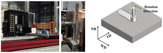
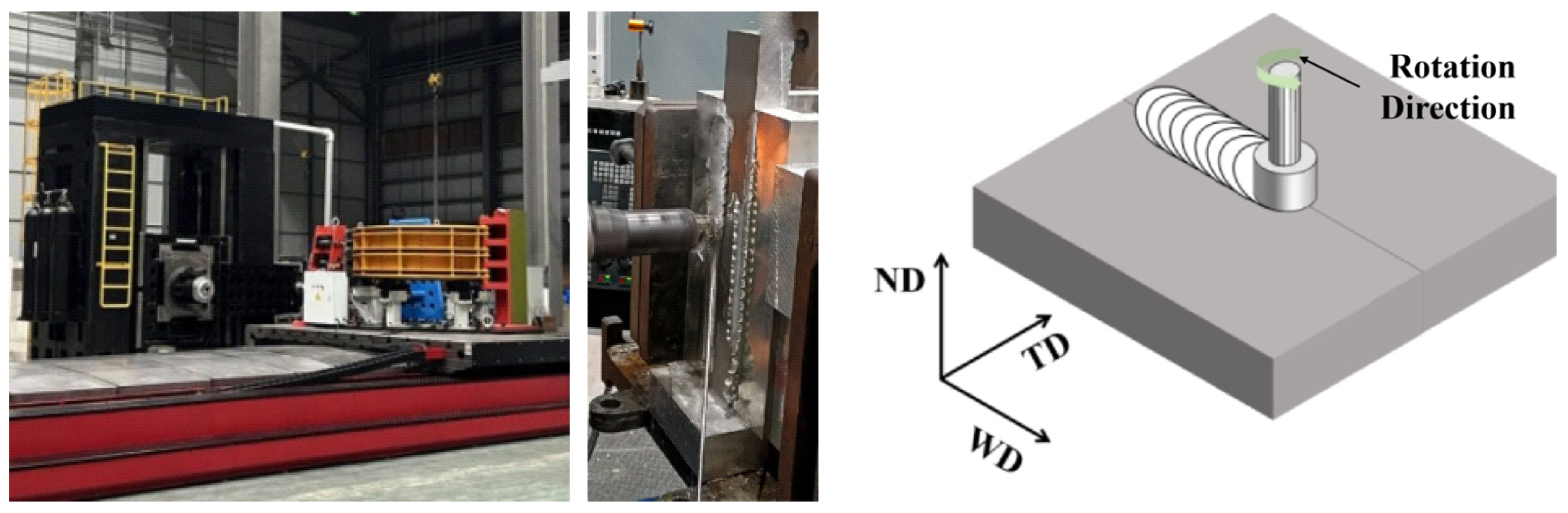
Prior to welding, the butt surfaces were cleaned, and the plates were firmly clamped to the workbench to prevent displacement of the base metal during welding, which could lead to welding failure. During welding, the plates were penetrated by the rotating welding tool, as pressure was applied to the material by the tool shoulder, the welding tool advanced steadily along the seam to complete the weld [27,28]. A tool rotation speed of 130 rpm and welding speed of 15 mm/min were used. A schematic of the welding procedure was shown in Figure 1.
Figure 1.
Schematic diagram of the aluminum alloy FSW process.
The detailed welding parameters were as follows: a tool rotation speed of 130 rpm, a welding speed of 15 mm/min, axial force 45 ± 2 kN, a tool tilt angle of 2.5° (toward the welding direction), and a plunge depth of 1 mm. Double-sided sequential welding was performed: first pass on the top side, then the workpiece was flipped and the second pass was applied from the bottom side. The plate was allowed to cool naturally to room temperature before the second pass.
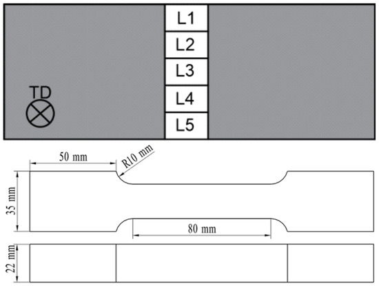
After welding, X-ray inspection was performed on the welded joint to determine whether any obvious welding defects were present. Subsequently, the welded plates were sectioned perpendicular to the weld seam for further analysis. Metallographic, tensile, and microhardness samples were prepared separately. After completing the welding process, metallographic specimens of AA 5052-H32 butt-welded FSW joints were prepared using the anodic coating method, which generated an optically anisotropic oxide film on the specimen surface through electrochemical means. The anode was an aluminum alloy specimen, and the cathode was a stainless steel plate. The voltage was set to a constant 30 V, with a current density of approximately 0.03 A/cm2. The coating duration was 60 s, and the tests were conducted at room temperature. Under polarized light in a LEIKA DMI3000 M microscope (Leica, Wetzlar, Germany), the varying interference colors resulting from differences in oxide film thickness due to distinct grain orientations clearly revealed the grain structure of the joint. During the tensile test, the tensile speed was set to 2 mm/min. Tensile samples were extracted from through-thickness layers: top surface layer (0–22 mm from top surface), upper subsurface layer (22–44 mm), intermediate layer (44–66 mm), lower subsurface layer (66–88 mm), and bottom surface layer (88–110 mm). Each location corresponds to a nominal layer label L1–L5. The dimensions of the tensile samples for the FSW welded joints were shown in Figure 2. The fracture morphology of the tensile samples was examined in detail by scanning electron microscopy, and the fracture mechanisms were analyzed.
Figure 2.
Tensile specimen schematic and size (L1–L5 are the positions selected for the tensile test specimens).
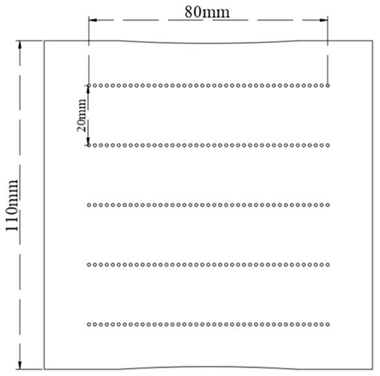
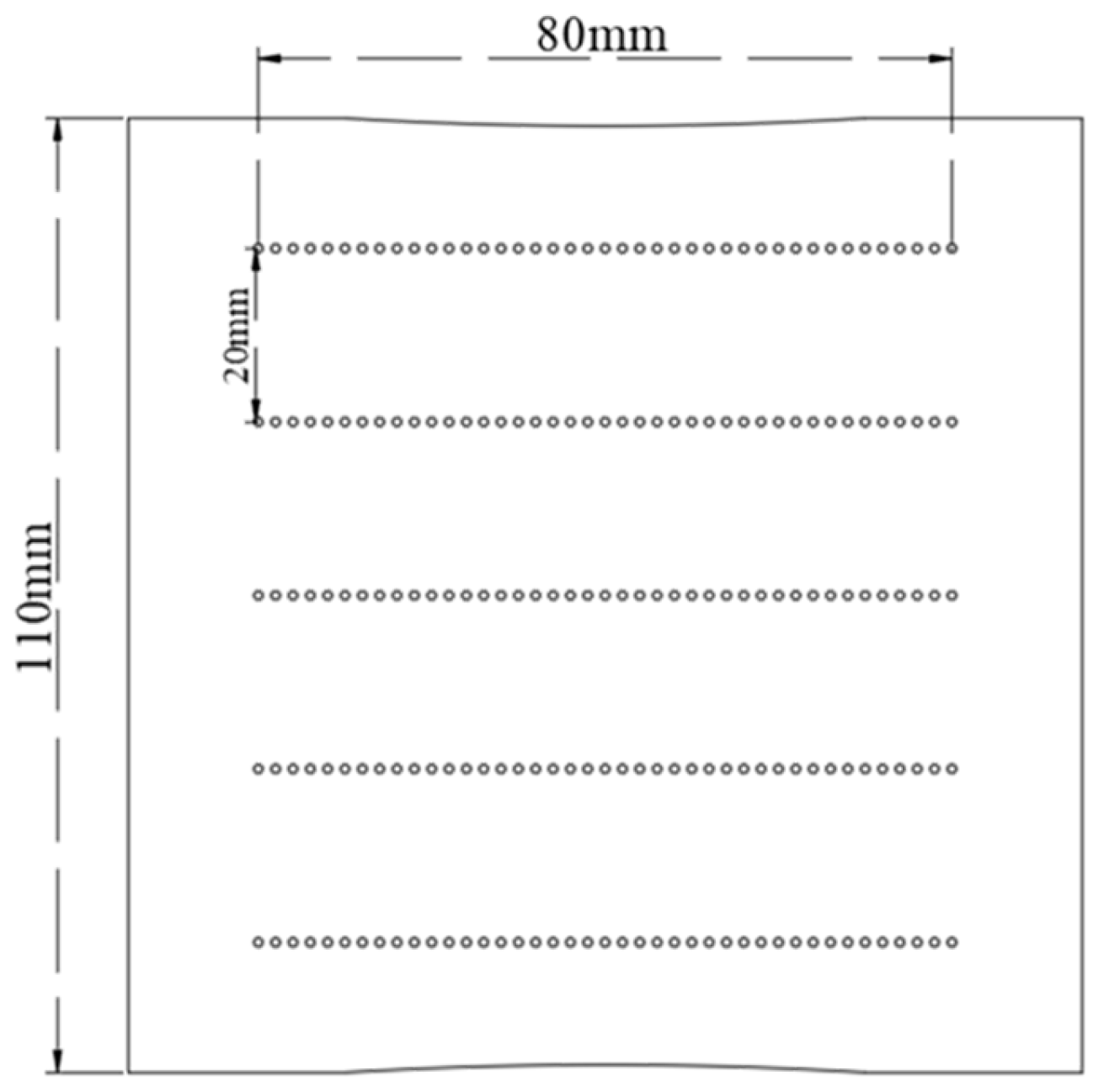
Microhardness tests were conducted at locations relative to the weld center-line (0 mm, ±20 mm, and ±40 mm), with each value point spaced 2 mm apart and each line measuring 80 mm in length, as shown in Figure 3. A 100 g load was applied for 15 s for each measurement, with a 2 mm spacing maintained between adjacent points. The resulting microhardness distribution (across the different regions of the FSW joints) was systematically analyzed and compared.
Figure 3.
Schematic diagram of the microhardness test location (The circles in the image indicate the hardness test points).
3. Results and Discussion
3.1. Macroscopic Analysis
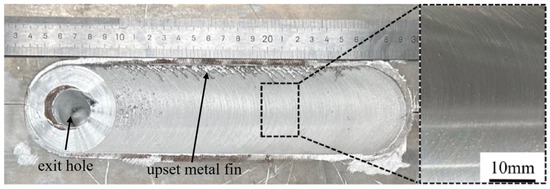
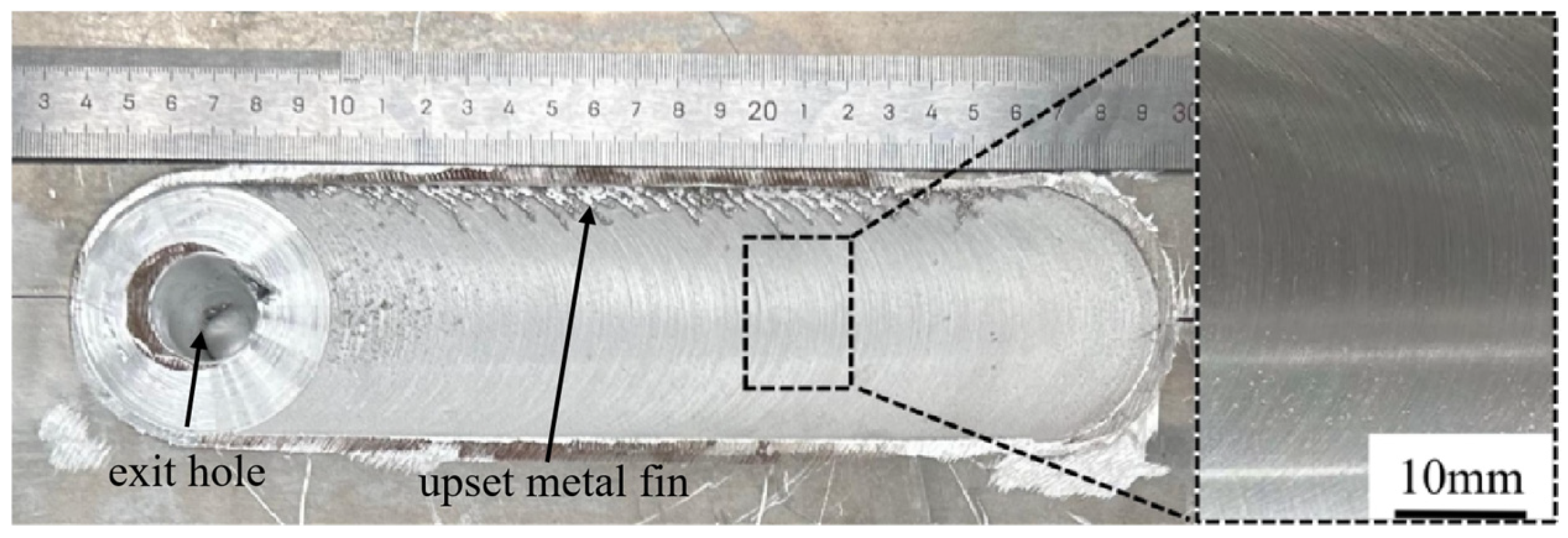
The macroscopic surface morphology of the double-sided butt FSW joint of the 110 mm-thick AA 5052-H32 is presented in Figure 4. The weld surface is relatively smooth, and uniformly distributed fish-scale patterns with moderate spacing and smooth semicircular features are observed. Only minimal flash is formed on the retreating side (RS) during welding, which results in an almost defect-free surface appearance for the double-sided butt FSW joint.
Figure 4.
Macroscopic morphology of welded seam.
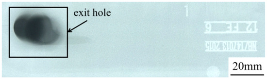
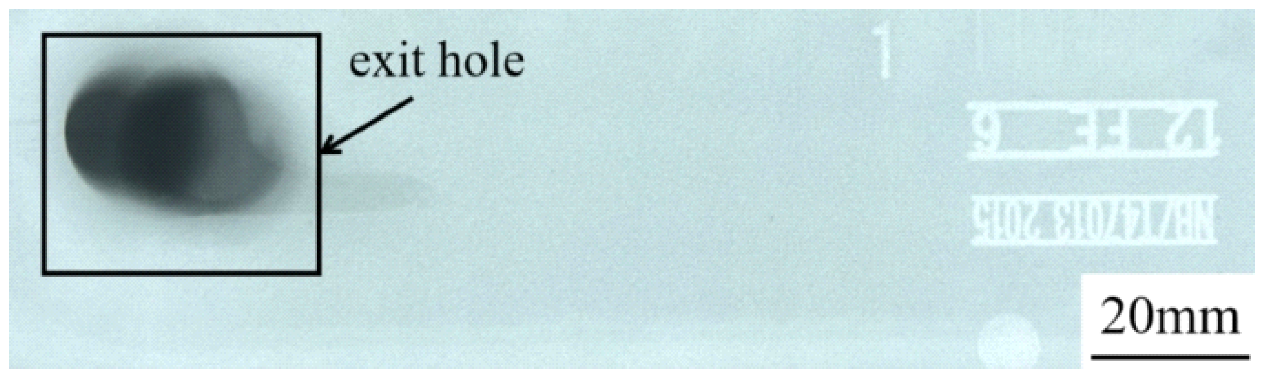
X-ray inspection is conducted using an MG226 machine to evaluate the internal quality of the welds, and the results are presented in Figure 5. Except for an exit hole at the end of the weld termination, no defects larger than the detection limit of the X-ray system (approximately 0.5 mm) are detected throughout the weld zone. Within this detection limit, the weld zone is free of cracks, pores, or other volumetric defects. The excellent internal integrity of the FSW joint is confirmed. Proper control of the welding parameters during the welding process is demonstrated, resulting in a high level of surface quality for the welded joint. This provides a solid foundation for the overall performance of the joint.
Figure 5.
X-ray results of FSW joint.
3.2. Microstructure Analysis
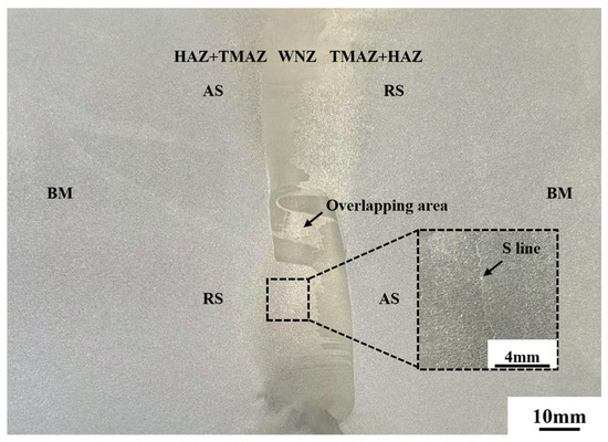
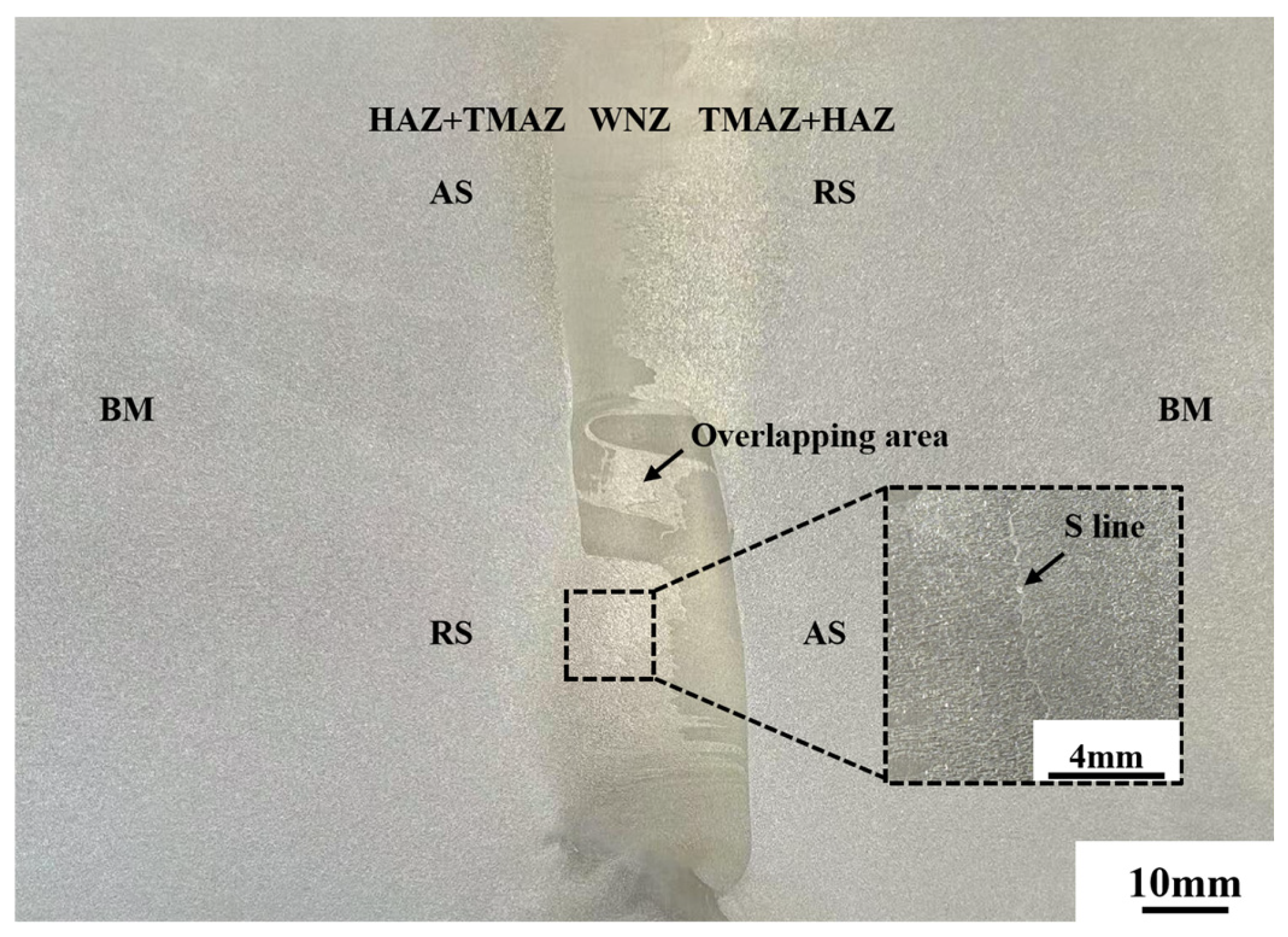
The cross-sectional morphology of the double-sided butt FSW joint in 110 mm-thick AA 5052-H32 is shown in Figure 6. A “double-cone” shape is exhibited by the weld, corresponding to the outer conical profile of the tool pin. A clear overlapping region of about 10 mm is observed between the first and second weld passes. The intermediate layer overlapping area refers to the zone along the thickness direction where the first and second weld passes intersect, typically located between 44 mm and 66 mm from the top surface. This region is approximately 10–15 mm thick.
Figure 6.
Cross-sectional macrographs of the welds.
Focusing on the first weld pass, the microstructure of the joint is analyzed based on typical friction stir weld zones: base material (BM), heat-affected zone (HAZ), thermo-mechanically affected zone (TMAZ), and weld nugget zone (WNZ). The weld microstructure was asymmetric across the transverse direction. The boundary between TMAZ and WNZ is distinct on the advancing side (AS) but is less distinct on the retreating side (RS). This asymmetry arises as the BM’s plastic deformation direction is parallel to the tool movement on the AS but opposite to it on the RS. Additionally, in the weld center, material is extruded along the welding tool rotation direction to the rear, accentuating the boundary on the AS but blurring it on the RS.
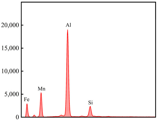
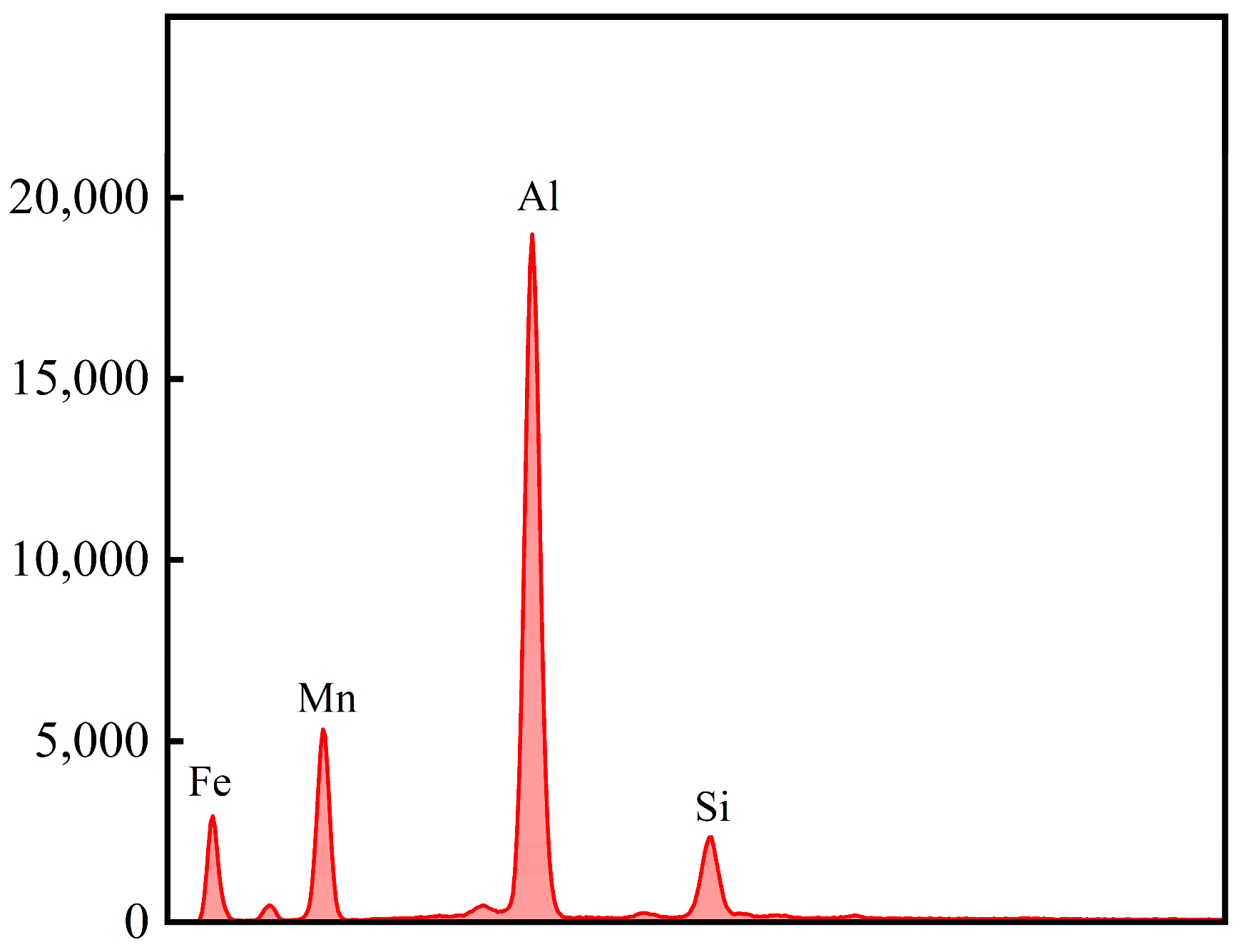
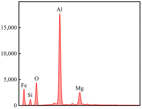
Energy dispersive spectroscopy analysis was performed using a scanning electron microscope equipped with an Oxford X-max 80 detector. The experimental conditions were: acceleration voltage 15 kV, working distance 15 mm, and acquisition time 60 s per spectrum. For the “S” line analysis (Figure 7), five point spectra were acquired along the line at intervals of approximately 5 μm. The analysis was repeated three times on different regions of the same sample to ensure reproducibility.
Figure 7.
EDS spectrum of the “S” line in FSW joint.
An “S”-shaped line, identified as fragmented oxide films, can be observed within the WNZ [29]. It is known that the “S” lines probably originate from the oxide layer on the initial butt surface, which was broken up, extruded and deformed during FSW. SEM coupled with energy dispersive spectroscopy point analysis (Figure 7) shows that these particles are composed of Al, O, Mg, Fe, and Si elements. Other elements such as Cu, Zn were not identified because their concentrations in the base alloy are below the detection limit of EDS (typically 0.1 at.%) under the present conditions. FSW involves relatively rapid heating and cooling, which may result in insufficient heat input for certain phenomena [30].
It should be noted that the AS and RS are reversed between the top and bottom passes. In the first pass, the tool travels from left to right, placing the AS on the left side of the weld. After flipping the workpiece for the second pass, placing the AS is on the right side of the weld. Consequently, the distinct boundary appears on the left at the top of the weld and on the right at the bottom, as observed in Figure 6.
It is important to note that the second weld pass was performed after flipping the workpiece. No significant difference was found between the first and second passes in terms of grain size in the WNZ and the width of the TMAZ. The intermediate layer overlapping area, which was welded last, experienced two thermal cycles but the thermal effect from the first pass on the second pass side was minimal because of the large thickness and the relatively low thermal conductivity of aluminum. Thus, only the first pass is analyzed here as representative of microstructural investigation. Metallographic images of the 110 mm-thick AA 5052-H32 double-sided butt FSW joint are shown in Figure 8, Figure 9 and Figure 10. The microstructure mainly consists of an α-Al matrix with dispersed second-phase particles.
Figure 8.
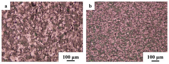
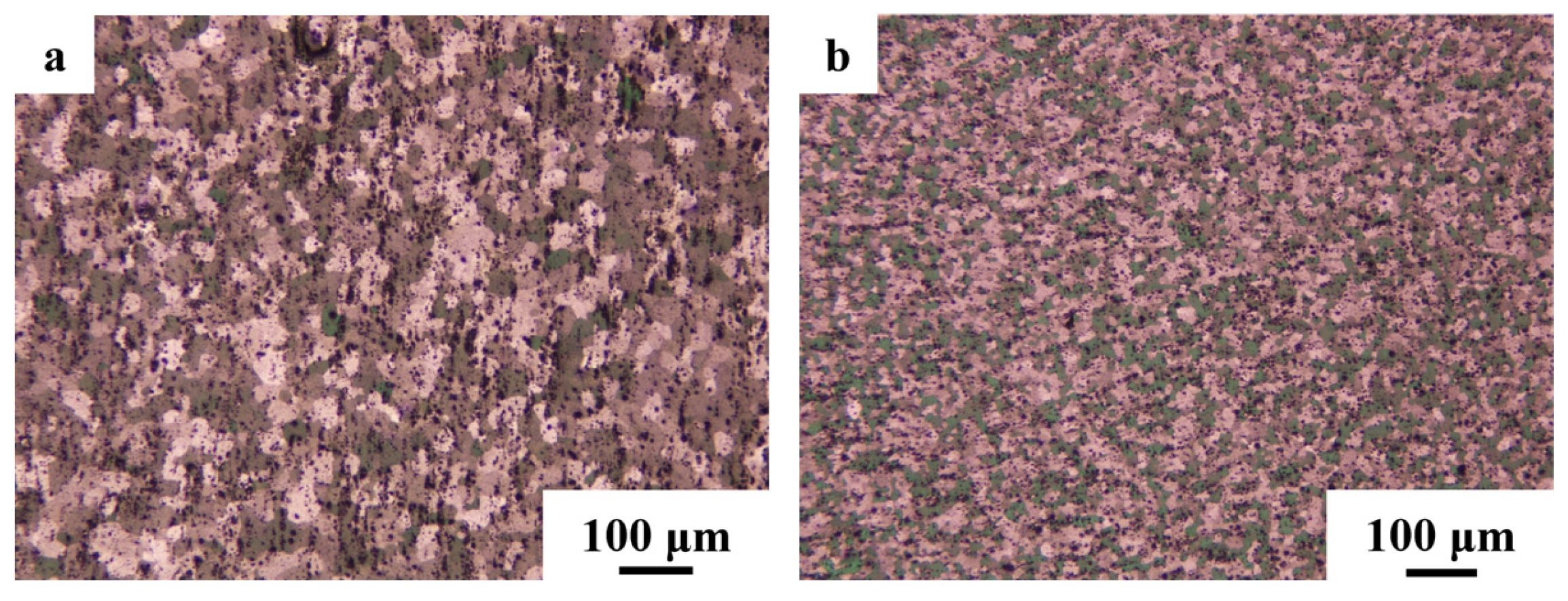
Metallographic morphology: (a) Weld nugget zone; (b) intermediate layer overlapping area.
Figure 9.
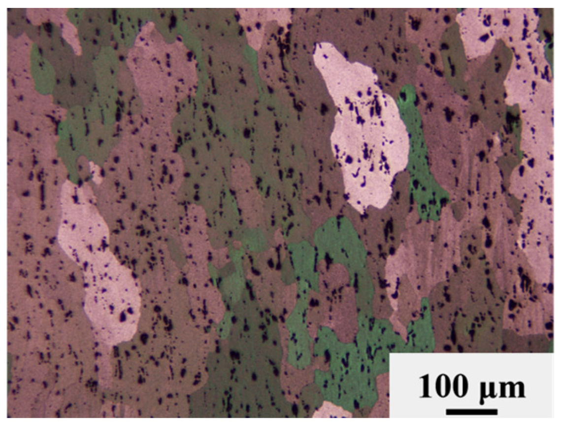
Metallographic morphology of the heat-affected zone of RS.
Figure 10.
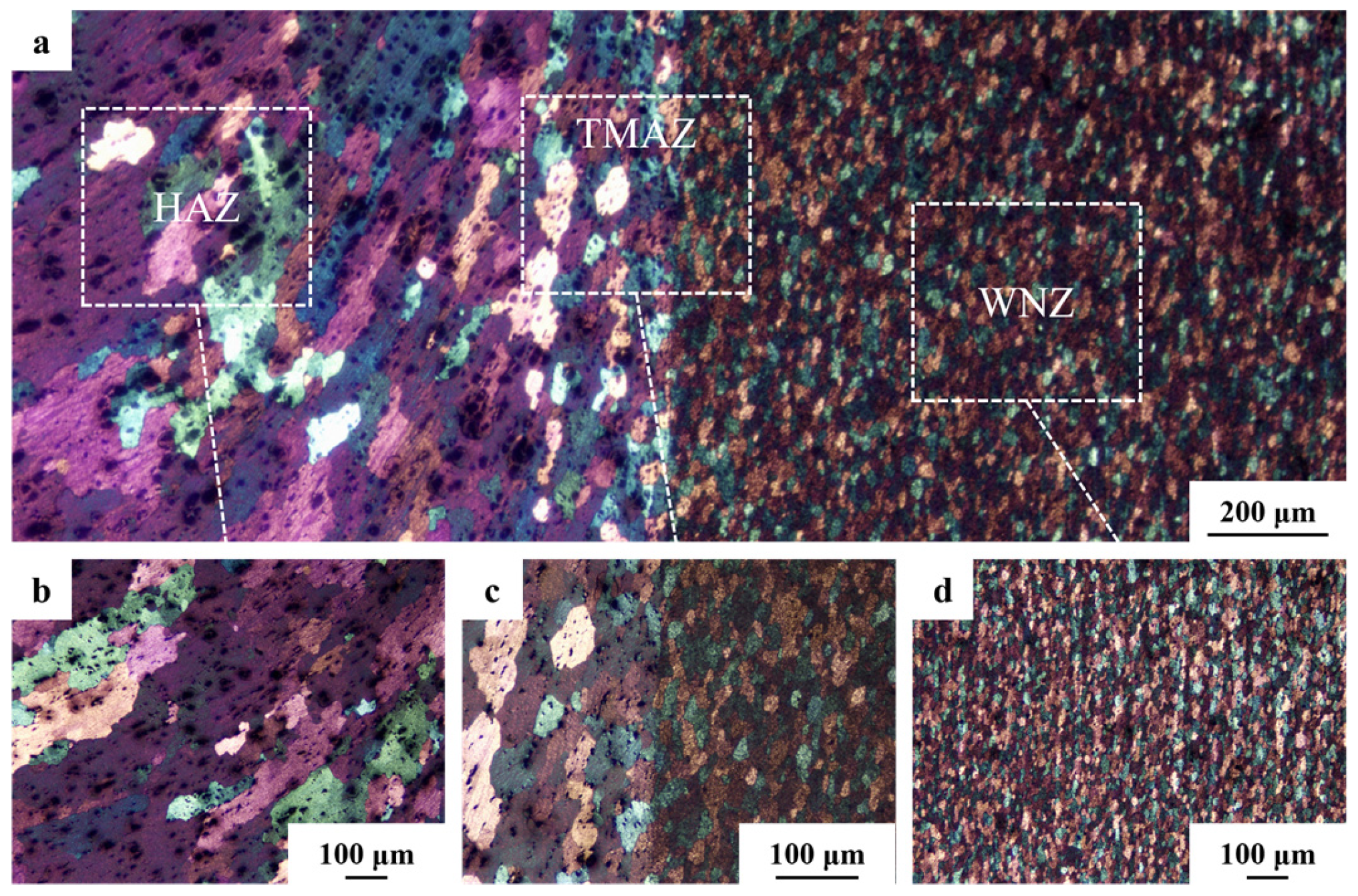
Metallographic morphology of AS: (a) Overall morphology; (b) heat-affected zone; (c) thermal-mechanically affected zone; (d) weld nugget zone.
The WNZ microstructure is shown in Figure 8a, where grains had undergone intense rotation, shear, and plastic deformation induced by mechanical stirring and elevated welding temperatures, resulting in a fine, uniform grain structure. In the intermediate layer overlapping area, due to undergoing two cycles of thermo-mechanical coupling, grains become finer, and friction generates less heat, leading to a microstructure characterized by finer grains [31]. Quantitative analysis using the linear intercept method revealed that the average grain size in the WNZ was 30.4 ± 1.2 μm, while that in the intermediate layer overlapping area was 14.3 ± 0.8 μm. The HAZ showed coarser grains of 125.6 ± 3.1 μm with elongated lath-like morphology. These quantitative values provide a basis for correlating microstructure with mechanical properties discussed in Section 3.3 and Section 3.4. Metallographic morphology of the RS (Figure 9) and AS (Figure 10) illustrates that the WNZ and the TMAZ are clear on the AS but indistinct on the RS. This difference mainly arises from the base metal flow behavior, as the welding tool’s rotational direction aligns with material flow on the AS, yielding stronger mechanical stirring and greater plastic deformation than on the RS.
Most heat input is generated by friction between the tool shoulder and the BM. The WNZ experiences the highest temperatures and plastic deformation due to combined effects of shoulder and pin, with temperatures reaching about 400 °C [18]. The fine equiaxed grain morphology is consistent with the occurrence of dynamic recrystallization as reported in similar Al alloys. The fine equiaxed grain morphology shown in Figure 8a is consistent with the occurrence of dynamic recrystallization (DRX) as reported in similar Al alloys [32].
In contrast, it is inferred from the finer grain size and less complete recrystallization that the intermediate layer overlapping area receives less heat—primarily from friction at the tool pin tip—resulting in lower thermal cycles, faster heat dissipation, and reduced shear stress. Meanwhile direct temperature measurements were not performed, consistent with the findings in the literature [32,33]. Consequently, plastic deformation is less intense, and insufficient energy for grain growth after fragmentation leads to a finer and more uniform grain structure than that in the WNZ.
In the HAZ, the limited heat input prevents complete DRX [34], resulting in coarser grains with distinctive lath-like morphology which, in turn, causes notable softening in the HAZ and reduces the weld’s mechanical properties [35].
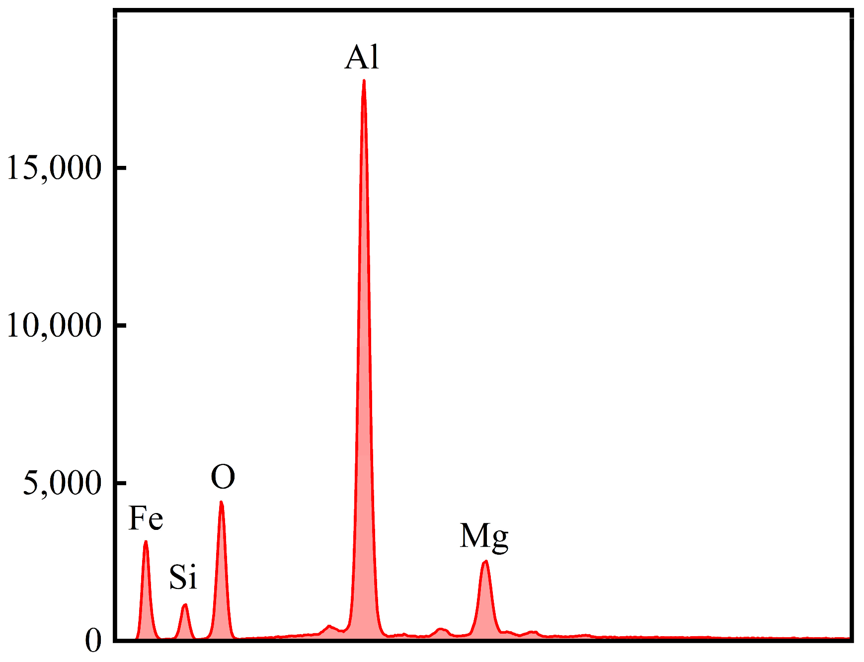
Point scan analysis of the double-sided butt FSW joint reveals that it appears as fine, highly dispersed particles distributed homogeneously within the weld (Figure 11). The white particulate phase contains Al, Fe, Mn, and Si with atomic percentages of 66.3%, 9.5%, 15.8%, and 7.8%, respectively. Based on morphology and composition, this phase is identified as the Al(MnFe)Si intermetallic compound [36,37].
Figure 11.
EDS spectrum of precipitated phase.
During FSW, intense plastic deformation and DRX accompany vigorous stirring and friction from the tool pin, which causes severe fragmentation of the second phase [32]. This fragmented phase is redistributed with the recrystallized grains, resulting in a uniform dispersion of the Al(MnFe)Si phase throughout the WNZ.
The Al(MnFe)Si intermetallic phase, identified by EDS, is known to form in Al-Mg-Mn alloys during solidification [37]. In FSW, these particles are fragmented and redistributed, acting as pinning sites for grain boundaries and thus contributing to grain refinement. In the present study, the finer dispersion of these particles in the intermediate layer overlapping region may contribute to the smaller dimple size observed in fractography.
3.3. Mechanical Property Analysis
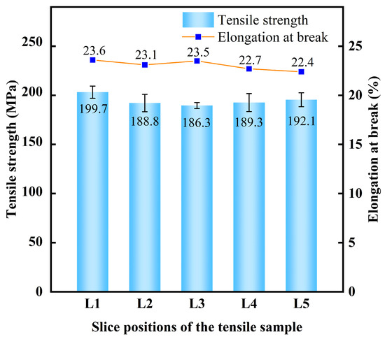
The variation in mechanical properties along with the thickness of the double-sided FSW butt joint in 110 mm-thick AA 5052-H32 is investigated through tensile testing of specimens extracted from different layers of the weld. Most tensile specimens, from the top surface layer L1 to the bottom surface layer L5, fracture near the interface between the HAZ and TMAZ of AS. During fracture, the specimens exhibit significant macroscopic plastic deformation, with fracture surfaces oriented approximately 45° to the principal stress direction, indicating shear-dominated failure.
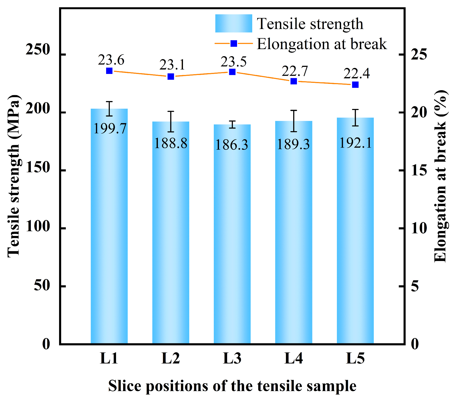
The tensile test results are summarized in Figure 12 with measurements taken three times per layer. The surface layer shows a tensile strength of 192.1 MPa (L5), about 83.5% of the base material strength, with an elongation of 22.4%. The subsurface layer exhibits a slightly lower tensile strength of 188.8 MPa (L2). The middle layer displays the lowest tensile strength at 186.3 MPa (L3), roughly 81% of the BM, identifying it as the weakest region of the joint. This joint efficiency is comparable to values reported for other thick-plate aluminum FSW joints. The present result falls within the expected range for similar processes. This reduction is attributed to the relatively low heat input during welding in the intermediate layer overlapping area, which hindered DRX and grain growth of fragmented grains, leading to decreased mechanical performance compared to other regions.
Figure 12.
Tensile test results (average of three specimens ± standard deviation).
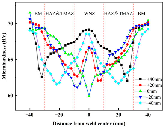
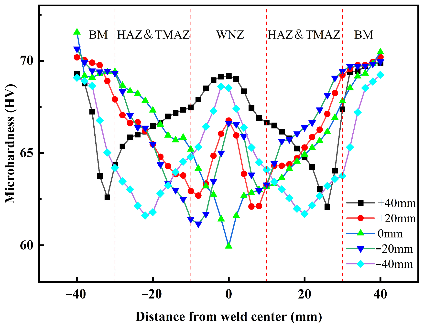
Microhardness testing conducted on polished cross-sections of the weld is shown in Figure 13. The middle layer exhibits a “V”-shaped hardness profile, with hardness gradually decreasing from the BM toward the WNZ and reaching a minimum of approximately 59 HV in the intermediate layer overlapping area of the two weld passes. In contrast, the surface layers (±40 mm) and the subsurface layers (±20 mm) display a “W”-shaped hardness distribution. Hardness decreases from the BM toward the HAZ, reaching a minimum at the interface between the TMAZ and HAZ.
Figure 13.
Microhardness distribution of welded joints.
The higher heat input generated by the larger contact area and downward pressure of the welding shoulder near the surface leads to a more uniform grain size distribution within the WNZ [38,39]. This enhances the deformation resistance and microhardness of the joint. Conversely, the intermediate layer overlapping area experiences insufficient heat, which limits grain growth after fragmentation. As a non-heat-treatable aluminum alloy, the mechanical properties of AA 5052-H32 rely primarily on solution strengthening and work hardening. Therefore, although grain refinement occurs in the overlapping zone of the intermediate layers, its contribution is insufficient to compensate for the reduction in solution strengthening and work hardening, as shown in Figure 13.
Compared to the WNZ, the intermediate layer overlapping area of the FSW joint exhibits significant softening. Moving from the weld surface toward the center, the position of minimum microhardness progressively shifts closer to the weld center. This trend results from the gradual decrease in heat input and mechanical stirring intensity along the thickness within the WNZ, causing the area of lowest hardness to migrate toward the center of the intermediate layer overlapping area.
To better understand the origin of the hardness reduction in the intermediate layer overlapping area, we correlated the local microhardness with the corresponding average grain size. The WNZ (grain size 30.4 μm) exhibited a hardness of 65 HV, while the intermediate layer overlapping area (grain size 14.3 μm) showed only 59 HV. The inverse grain size–hardness relationship indicates that grain refinement is not the dominant strengthening mechanism in this non-heat-treatable alloy.
3.4. Fracture Analysis
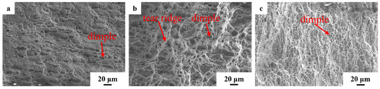
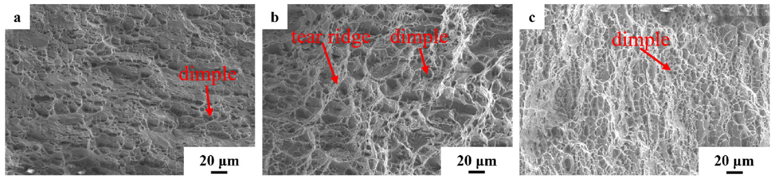
Fracture of the tensile specimens of the double-sided butt FSW joint in 110 mm-thick AA 5052-H32 is consistently observed at the interface between the HAZ and TMAZ, identifying this region as the weakest in the joint. The fracture morphology of these tensile specimens is presented in Figure 14, revealing typical ductile fracture features characterized by dimples.
Figure 14.
Tensile fracture morphology of each layer of welded joint samples: (a) Surface layer; (b) subsurface layer; (c) intermediate layer.
The fracture morphology of the joint’s surface layer is shown in Figure 14a, where large dimples are observed, surrounded by a fine network of voids. Second-phase particles, detached during fracture, are found within these large dimples. Their presence enhances resistance to deformation and contributes to strengthening. The subsurface layer’s fracture morphology is depicted in Figure 14b, where the dimples are smaller and tear ridges are noticeable. The fracture morphology of the middle layer is illustrated in Figure 14c. Because the overlap region is exposed to two thermal and shear cycles during welding, both grain size and precipitate dimensions are reduced, resulting in significantly smaller dimples compared to the surface layer.
The surface layer dimples have an average diameter of 5.3 ± 0.5 μm, and the subsurface layer dimples have an average diameter of 4.5 ± 0.8 μm. The middle layer dimples average diameter 2.1 ± 0.4 μm. The progressive decrease in dimple size from the surface to the middle layer correlates well with the decrease in tensile strength and hardness.
By superimposing the fracture location onto the microhardness distribution map, it is evident that the TMAZ/HAZ interface coincides with the minimum hardness region for each layer: 63 HV for the surface layers and 59 HV for the intermediate layer. This region also corresponds to the steepest microstructural gradient, where coarse lath-like HAZ grains transition to elongated TMAZ substructures without full recrystallization. The consistent fracture at this interface is therefore attributed to the combined effects of localized softening and strain incompatibility.
The microscopic fracture features further support this correlation: the surface layer shows large dimples typical of ductile failure in a relatively uniform microstructure, while the intermediate layer exhibits much finer dimples due to the finer grain size and precipitate distribution in the overlapping region.
4. Conclusions
The microstructure and mechanical properties of double-sided butt friction stir welded joints of 110 mm-thick AA 5052-H32 plates are investigated in this study. Excellent surface morphology is exhibited by the weld, and the absence of internal defects within the joint was confirmed by X-ray inspection. The findings reported in this study are strictly valid for the specific range of welding parameters investigated: tool rotation speed of 130 rpm, welding speed of 15 mm/min, tool tilt angle of 2.5°, plunge depth of 1 mm, and plate thickness of 110 mm for AA 5052-H32.
(1) The weld nugget zone exhibits a uniform grain structure formed by intense stirring and frictional heat from the tool pin. A clear boundary between the weld nugget zone and the thermal-mechanically affected zone of the advancing side is observed, while the interface between the weld nugget zone and the thermal-mechanically affected zone of the retreating side is less distinct.
(2) A characteristic “W”-shaped microhardness profile is revealed in the surface and subsurface layers of the weld. Grain-size variations are observed on the advancing side, with the lowest hardness located at the interface between the thermal-mechanically affected zone and the heat affected zone of the advancing side. In contrast, the middle layer gradually decreases in hardness from the base material toward the weld nugget zone. The minimum hardness is measured in the intermediate layer overlapping area. In the intermediate layer overlapping zone, two thermal cycles cause significant loss of work hardening, while the limited grain refinement cannot compensate for these losses, resulting in the lowest hardness. The “V”-shaped hardness profile in the mid-thickness is a distinctive feature of double-sided FSW of ultra-thick plates and should be considered in joint design.
(3) The tensile strength of the double-sided butt friction stir welded joint in AA 5052-H32 plate is 81% of that of the base material. The intermediate layer overlapping area, which experienced lower heat input, exhibited incomplete grain growth of fragmented particles. This microstructural feature resulted in the weakest mechanical performance, both in terms of hardness and tensile strength. Fracture morphologies from all layers are observed to demonstrate typical ductile features, consisting of dimples of variable sizes and tear ridges. Notably, fractures are consistently observed at the interface between the thermal-mechanically affected zone and the heat affected zone which confirms this region as the joint’s weakest point.
Author Contributions
Methodology: Z.S., W.L., X.Z. and J.Z.; Investigation: Z.S. and W.L.; Formal analysis: Z.S.; Data curation: Z.S. and X.Z.; Writing—original draft: Z.S.; Writing—review and editing: K.Y.; Visualization: K.Y.; Validation: K.Y., W.L. and X.Z.; Supervision: K.Y.; Resources: J.Z. All authors have read and agreed to the published version of the manuscript.
Funding
This research received no external funding.
Data Availability Statement
The original contributions presented in this study are included in the article material. Further inquiries can be directed to the corresponding author.
Conflicts of Interest
Author Wenbin Lu was employed by the companies Changzhou Lemeng Pressure Vessel Co., Ltd. and Jiangsu Lemeng Precision Technology Co., Ltd. The remaining authors declare that the research was conducted in the absence of any commercial or financial relationships that could be construed as a potential conflict of interest.
References
- Meghnath, S.; Baran, A.P. Formation of intermetallic compounds (IMCs) in FSW of aluminum and magnesium alloys (Al/Mg alloys)—A review. Mater. Today Commun. 2022, 33, 105017. [Google Scholar]
- Kaushik, P.; Dwivedi, K. Comprehensive analysis of friction stir welding of high-temperature P22 steel and Al 5052 alloy: Metallurgical mixing, mechanical properties, and failure mechanism. Weld. World 2025, 69, 1991–2002. [Google Scholar] [CrossRef] [Scilit]
- Sen, M.; Shankar, S.; Chattopadhyaya, S. Investigations into FSW joints of dissimilar aluminum alloys. Mater. Today Proc. 2020, 27, 2455–2462. [Google Scholar] [CrossRef] [Scilit]
- Ding, T.; Yan, H.; Chen, J.; Xia, W.; Su, B.; Zhu, H. Microstructure evolution and recrystallization mechanisms of high Mg alloyed Al-Mg alloy during friction stir welding with different cooling media. J. Mater. Eng. Perform. 2022, 32, 3809–3820. [Google Scholar] [CrossRef] [Scilit]
- Sasikumar, A.; Gopi, S.; Mohan, D.G. Prediction of filler added friction stir welding parameters for improving corrosion resistance of dissimilar aluminum alloys 5052 and 6082 joints. Adv. Mater. Sci. 2022, 22, 79–95. [Google Scholar] [CrossRef] [Scilit]
- Tang, Q.; Liu, M.; Sun, M.; Zhao, G.; Li, J.; Li, H. Investigation into the deformation behavior and formability of 5052-O aluminum alloy under various high-temperature conditions. Adv. Eng. Mater. 2025, 27, 2501223. [Google Scholar] [CrossRef] [Scilit]
- Shanavas, S.; Dhas, J.E.R.; Murugan, N. Weldability of marine grade AA 5052 aluminum alloy by underwater friction stir welding. Int. J. Adv. Manuf. Technol. 2018, 95, 4535–4546. [Google Scholar] [CrossRef] [Scilit]
- Yan, H.; Zeng, X.; Cui, Y.; Zou, D. Numerical and experimental study of residual stress in multi-pass laser welded 5A06 alloy ultra-thick plate. J. Mater. Res. Technol. 2024, 28, 4116–4130. [Google Scholar] [CrossRef] [Scilit]
- Sun, T.; Roy, M.J.; Strong, D.; Simpson, C.; Withers, P.J.; Prangnell, P.B. Weld zone and residual stress development in AA7050 stationary shoulder friction stir T-joint weld. J. Mater. Process. Technol. 2018, 263, 256–265. [Google Scholar] [CrossRef] [Scilit]
- Patel, V.; Li, W.; Wang, G.; Wang, F.; Vairis, A.; Niu, P. Friction stir welding of dissimilar aluminum alloy combinations: State-of-the-Art. Metals 2019, 9, 270. [Google Scholar] [CrossRef] [Scilit]
- Devang, S.; Wenya, L.; Vivek, P. Stationary shoulder friction stir welding-low heat input joining technique: A review in comparison with conventional FSW and bobbin tool FSW. Crit. Rev. Solid State Mater. Sci. 2022, 47, 865–914. [Google Scholar]
- Reza-E-Rabby, M.; Das, H.; Wang, T.; Komarasamy, M.; Whalen, S.A.; Grant, G.J. High-speed friction stir butt welding of 25.4 mm thick 7175-T79 aluminum alloy. Manuf. Lett. 2023, 38, 1–5. [Google Scholar] [CrossRef] [Scilit]
- Chen, C.; Zhu, Y.; He, Z.; Lu, H.; Xu, W.; Cui, T.; Liu, W.; Qiu, C.; Gao, Z. A comparative study in microstructure and mechanical properties of symmetric and asymmetric double-sided FSW joints of AA7A65. Materials 2025, 18, 645. [Google Scholar] [CrossRef] [Scilit]
- Xia, C.; Xu, Y.; Liu, Q.; Ke, L. Evolution of intermetallic compound and eutectic of thick plate Al/Mg friction stir welded joints: Effect of material position. J. Mater. Eng. Perform. 2026, 35, 11608–11618. [Google Scholar] [CrossRef] [Scilit]
- Canaday, C.T.; Moore, M.A.; Tang, W.; Reynolds, A. Through thickness property variations in a thick plate AA7050 friction stir welded joint. Mater. Sci. Eng. A 2013, 559, 678–682. [Google Scholar] [CrossRef] [Scilit]
- Liu, S.; Chen, F.; Gao, Y. Effect of progressive pin and pre-set wires on the quality of corner forming of Al/Cu FSW T-lap joints. J. Mater. Eng. Perform. 2025, 34, 15774–15786. [Google Scholar] [CrossRef] [Scilit]
- Guo, N.; Fu, Y.; Wang, Y.; Meng, Q.; Zhu, Y. Microstructure and mechanical properties in friction stir welded 5A06 aluminum alloy thick plate. Mater. Des. 2017, 113, 273–283. [Google Scholar] [CrossRef] [Scilit]
- Li, L.; Shao, Z.; Liu, W.; Liu, Y.; Zhao, S.; Wei, Y.; Zhang, J.; Wang, X.; Hou, H. Channel microenvironment-controlled pillared MOF as efficient triboelectric nanogenerator material for self-powered degradation of organic pollutants. Energy Environ. Mater. 2026, e70280. [Google Scholar] [CrossRef] [Scilit]
- Li, S.S.; Yang, H.Y.; Dong, B.X.; Shu, S.L.; Liu, T.S.; Qiu, F.; Jiang, Q.C. In depth analysis of microstructure and mechanical properties of joints in thick plate friction stir welding of high-strength Al-Zn-Mg-Cu alloy. Mater. Charact. 2025, 228, 115401. [Google Scholar] [CrossRef] [Scilit]
- Mori, M.; Ban, T.; Takeuchi, H.; Morisada, Y.; Fujii, H. Friction stir welding of thick steel plate using silicon nitride tool: Regular article. ISIJ Int. 2024, 64, 1699–1704. [Google Scholar] [CrossRef] [Scilit]
- Liu, H.B.; Wang, T.D.; Liu, G.Y.; Xie, S.F.; Chu, S.Q.; Xie, B.; Yang, S.L.; Wang, P.Y. Local microstructure and strengthening mechanisms of double-sided friction stir welded Al-Mg-Mn-Er alloy joint. Trans. Nonferrous Met. Soc. China 2023, 33, 2588–2598. [Google Scholar] [CrossRef] [Scilit]
- Su, M.; Qi, X.; Xu, L.; Feng, Q.; Han, Y.; Zhao, L. Microstructural and mechanical analysis of 6063-T6 aluminum alloy joints bonded by friction stir welding. J. Mater. Sci. 2022, 57, 15078–15093. [Google Scholar] [CrossRef] [Scilit]
- Liu, B.; Liu, F.; Song, F. Coupling sPCA-based statistical modeling with deep residual networks considering thermal effect for deformation forecasting in high dams. Struct. Control Health Monit. 2025, 2025, 6688960. [Google Scholar] [CrossRef] [Scilit]
- Yacout, G.G.; Shash, A.Y.; Hegazi, H.A.; El-Sherbiny, M.G. Comparative experimental and statistical study of conventional and bobbin tool friction stir welding of AA6061-T6 aluminum alloy. J. Eng. Appl. Sci. 2025, 72, 255. [Google Scholar] [CrossRef] [Scilit]
- Zhou, B.; Shan, X.; Xiao, J.; Liu, H.; Meng, S.; Lin, Z. Experimental investigation and process parameter optimization of simultaneous staggered double-sided friction stir welding. Int. J. Adv. Manuf. Technol. 2025, 141, 3199–3210. [Google Scholar] [CrossRef] [Scilit]
- Lunetto, V.; De Maddis, M.; Lombardi, F.; Spena, P.R. A review of friction stir welding of industrial alloys: Tool design and process parameters. J. Manuf. Mater. Process. 2025, 9, 36. [Google Scholar] [CrossRef] [Scilit]
- Wang, X.; Morisada, Y.; Fujii, H. Interface strengthening in dissimilar double-sided friction stir spot welding of AZ31/ZK60 magnesium alloys by adjustable probes. J. Mater. Sci. Technol. 2021, 85, 158–168. [Google Scholar] [CrossRef] [Scilit]
- Zhang, Z.; Wu, Q.; Grujicic, M.; Wan, Z.Y. Monte Carlo simulation of grain growth and welding zones in friction stir welding of AA6082-T6. J. Mater. Sci. 2016, 51, 1882–1895. [Google Scholar] [CrossRef] [Scilit]
- Colegrove, P.; Shercliff, H. Two-dimensional CFD modelling of flow round profiled FSW tooling. Sci. Technol. Weld. Join. 2004, 9, 483–492. [Google Scholar] [CrossRef] [Scilit]
- Chen, H.; Yan, K.; Lin, T.; Chen, S.-B.; Jiang, C.-Y.; Zhao, Y. The investigation of typical welding defects for 5456 aluminum alloy friction stir welds. Mater. Sci. Eng. A 2006, 433, 64–69. [Google Scholar] [CrossRef] [Scilit]
- Rahmatian, B.; Mirsalehi, S.; Dehghani, K. Metallurgical and mechanical characterization of double-sided friction stir welded thick AA5083 aluminum alloy joints. Trans. Indian Inst. Met. 2019, 72, 2739–2751. [Google Scholar] [CrossRef] [Scilit]
- Iqbal, P.; Tripathi, A.; Jain, R.; Mahto, R.P.; Pal, S.; Mandal, P. Numerical modelling of microstructure in friction stir welding of aluminium alloys. Int. J. Mech. Sci. 2020, 185, 105882. [Google Scholar] [CrossRef] [Scilit]
- Patel, V.; De Backer, J.; Hindsefelt, H.; Igestrand, M.; Azimi, S.; Andersson, J.; Säll, J. High speed friction stir welding of AA6063-T6 alloy in lightweight battery trays for EV industry: Influence of tool rotation speeds. Mater. Lett. 2022, 318, 132135. [Google Scholar] [CrossRef] [Scilit]
- Huang, K.; Loge, R. A review of dynamic recrystallization phenomena in metallic materials. Mater. Des. 2016, 111, 548–574. [Google Scholar] [CrossRef] [Scilit]
- Liu, F.; Fu, L.; Chen, H. High speed friction stir welding of ultra-thin AA6061-T6 sheets using different backing plates. J. Manuf. Process. 2018, 33, 219–227. [Google Scholar] [CrossRef] [Scilit]
- Shinozaki, T.; Shimojo, J.; Akamatsu, H.; Matsumoto, K.; Shinya, T.; Mizutani, J.; Nakabayashi, Y. Effects of the amount of Mg on the precipitation behavior of β phase and its modeling in Al-Mn-Mg alloys. Mater. Trans. 2022, 63, 845–853. [Google Scholar] [CrossRef] [Scilit]
- Dai, J.; Chen, H.; Cui, Y.; Dan, C.; Zong, S.; Yang, C.; Li, H.; Chen, X.; Zhong, H.; Wang, H.; et al. Deformation mechanisms of Al alloys containing shearable/non-shearable L12 precipitates: A comparative study under varied slip system activations. Acta Mater. 2025, 301, 121607. [Google Scholar] [CrossRef] [Scilit]
- Zhao, Z.; Liang, H.; Zhao, Y.; Yan, K. Effect of exchanging advancing and retreating side materials on mechanical properties and electrochemical corrosion resistance of dissimilar 6013-T4 and 7003 aluminum alloys FSW joints. J. Mater. Eng. Perform. 2018, 27, 1777–1783. [Google Scholar] [CrossRef] [Scilit]
- Wang, H.; Chang, S.; Zhou, Z.; Wang, W. Effect of TIG remelting on the microstructure, mechanical properties, and corrosion behavior of 5052 aluminum alloy joints in MIG welding. J. Mater. Res. Technol. 2024, 32, 2255–2267. [Google Scholar] [CrossRef] [Scilit]

Disclaimer/Publisher’s Note: The statements, opinions and data contained in all publications are solely those of the individual author(s) and contributor(s) and not of MDPI and/or the editor(s). MDPI and/or the editor(s) disclaim responsibility for any injury to people or property resulting from any ideas, methods, instructions or products referred to in the content. |
© 2026 by the authors. Licensee MDPI, Basel, Switzerland. This article is an open access article distributed under the terms and conditions of the Creative Commons Attribution (CC BY) license.