


Abstract
In layered systems with porous substrates and a dense solid surface, stiffness and strength are inherently coupled through porosity-dependent relations, influencing their load-bearing behaviour. This work presents a systematic methodology for the assessment and design of such layer-substrate systems based on a criterion of balanced material utilization. A dimensionless parameter is defined to characterize the stress state in both components relative to their admissible limits, from which the optimal layer thickness is determined at equal stress levels in both constituents. Stress distributions are calculated using a numerical half-space model for layered contacts and evaluated through material-dependent equivalent stress criteria. The relationship between material utilization and load-carrying capacity is reduced to a scaling factor that combines the influence of porosity-dependent parameters. The approach establishes a direct link between the governing material parameters and structural design variables. Across the investigated parameter range, the utilization rate scales linearly with optimal layer thickness, whereas the load-carrying capacity follows a cubic relation. For a representative Ashby strength scaling coefficient of , for example, a substrate porosity of 90% leads to a scaling factor of 1.6, corresponding to a possible load amplification of 60% relative to the homogeneous reference.
1. Motivation and State of the Art
The contact behaviour of machine elements is governed, among other factors, by the properties of the contacting bodies, especially by their material and surface characteristics. Against this background, the targeted modification of these properties offers a promising opportunity to deliberately influence the interaction of the contact partners. The use of coated materials is therefore well established in machine elements [1] and is employed across various fields of application, such as to increase corrosion resistance or to provide wear protection [2].
Adding to traditional coating processes [3], additive manufacturing (AM) and the development of metal foams present new possibilities in the functional design of machine elements and their contact behaviour. Metal foams combine low density with a high stiffness to weight ratio as well as pronounced energy absorption [4]. In addition to lightweight design, their structure enables multifunctional use, such as the possibility for improved cooling [5]. The combination of a solid surface layer with a porous core enables a functional separation between both and thereby opens additional design possibilities beyond monolithic systems. Due to the layer-wise building process, a targeted combination of materials and the incorporation of porous structures, AM allows the properties of a component to be specifically influenced, thus enabling the realization of such functionally graded components [6,7]. Within the Collaborative Research Centre CRC/TRR 375, AM components with material and porosity gradation, referred to as hybrid porous structures (HyPo), are being investigated [8]. HyPo materials denote additively manufactured multi-material systems in which both the composition and the local porosity can be varied spatially during the manufacturing process. For this purpose, manufacturing strategies are being developed, to enable controlled material and porosity gradation as well as strategies for joining porous and dense structures [9,10,11,12,13]. These HyPo materials therefore differ from conventional foams, which can be manufactured by various production processes [14], as they allow material and porosity gradation, thus enabling spatial control of the mechanical properties and additional functionality in combination with a freely formable closed surface.
Such HyPo structures can, for instance, be applied in machine elements by combining a load-adapted porous core structure with hard, fatigue-resistant dense surfaces, thus meeting the requirements of highly loaded machine elements such as bearings with a wear-resistant surface while maintaining a core resistant to failure. These material concepts impose new requirements on component design. In particular, coupling a stiff surface layer with a compliant porous substrate leads to altered stress distributions and gradients. A comprehensive stress analysis is therefore a prerequisite for the reliable design and optimization of layer-substrate systems.
For this purpose, various methodological approaches can be found in the literature. Finite element simulations (FE) were used to investigate plastic flow in coated contacts and to quantify its dependence on parameters such as coating thickness and elastic mismatch. GOLTSBERG et al. analyzed sphere–plane contacts and defined the onset of yielding by the first occurrence of the VON MISES yield criterion in either the coating or the substrate and described the maximum VON MISES stress in the coating and substrate of an elastic spherical contact as a function of coating thickness and elastic modulus ratio [15,16]. This approach was further extended to distinguish between a first and second yielding event [17]. CHEN et al. used FE models to define yield-modes, which locate the onset of plastic flow in a coated spherical contact as a function of dimensionless coating thickness and the elasticity and strength ratios in the layer, interface, or substrate [18].
Extensive parametric studies have also been carried out based on analytical half-space models. Solutions for layered systems were originally derived for prescribed normal loads [19] and later generalized to arbitrary normal load distributions [20,21]. Building on this, O’SULLIVAN and KING determined stress fields and displacements using PAPKOVICH–NEUBER potentials and double Fourier transformation to derive the frequency response function for contacts subjected to combined normal and tangential loads [22]. The conjugate gradient method and discrete convolution methods in combination with fast Fourier transformation have become established numerical solution strategies [23,24]. On this basis, elastic stress and displacement fields in bi- and multilayer systems have been analyzed in multiple studies [25,26,27], with the maximum VON MISES stress and its location used to identify critical parameter ranges [28,29].
While the onset of yielding is identified via locally normalized VON MISES stresses in the coating and substrate and coating thicknesses are optimized with regard to maximum critical loads, the approach is governed by reaching a defined local target value. An explicit design function that simultaneously accounts for strength reserves of layer and substrate material and systematically relates their utilization rates has not yet been formulated. Although GOLTSBERG et al. introduced implicit equal utilization consideration in the limiting case of yielding using the ratios of critical loads, it was not used as an explicit optimization and design criterion [15,16,17,18]. The models developed provide stress fields in the surface layer and substrate, but do not address the question of balanced utilization of both materials within a wide load range and in the domain below the yield point. For machine elements, balanced utilization is advantageous because it avoids a disproportionate mechanical loading of either the layer or the substrate, whereas the respective counterpart maintains unused reserves. In layered systems, a balance-oriented approach thus enables a more efficient use of material capacity and provides a design-oriented criterion for dimensioning.
Against this background and based on the research presented, this contribution introduces a balancing criterion in which the strength reserve in the layer and substrate are normalized by their admissible limits and a design methodology is then formulated to equalize the utilization rates while complying with the respective strength constraints. Furthermore, the established approaches and proposed framework are extended to layered systems with a solid outer layer and a porous substrate. In these systems, stiffness and admissible stress are coupled through porosity-dependent scaling laws [30]. The present work analyses how these porosity-dependent scaling laws govern the mechanical response of layered porous systems and how the resulting stress state and load-carrying capacity can be expressed as functions of these relationships.
2. Methodology
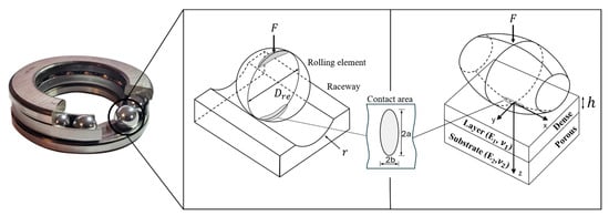
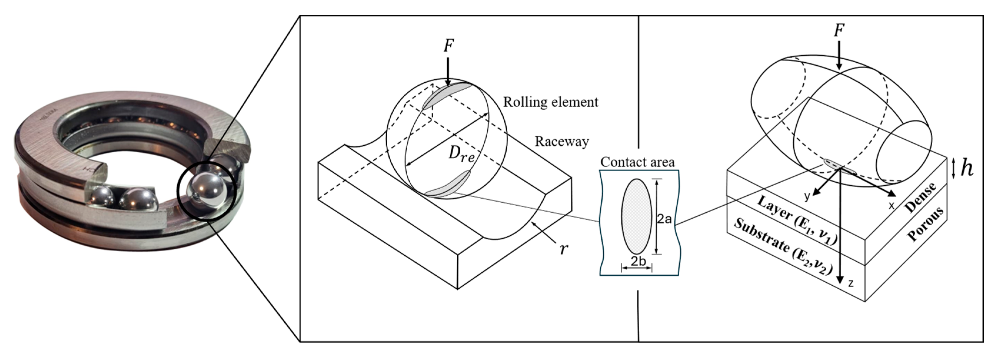
The numerical stress analysis of material and porosity gradation is carried out exemplarily for the application case of a thrust ball bearing with a raceway made of HyPo material. The simulation study is conducted using a 51208 bearing as a reference case, with the input parameters described in Section 2.2. The simulations were performed in MATLAB (MathWorks, Natick, MA, USA), version 2025b. The simulation approach is based on the work of WANG et al. [25] and is outlined in Section 2.1. The analysis considers a single rolling element, which is transformed into an equivalent elliptical body and simulated in a plane contact. The investigated layered systems consist of a dense surface layer of thickness on a porous substrate, as illustrated in Figure 1.
Figure 1.
Thrust ball bearing (left), its contact modelling (centre) based on [31] and equivalent model for stress computation (right), assuming an ideally bonded interface.
2.1. Formulation of Stresses and Displacements in the Layered System
Layer and substrate are modelled as linear elastic, homogeneous, and isotropic materials. Plasticity is not explicitly simulated, but instead yielding is assessed by comparing the calculated equivalent stresses with the respective yield limits. An ideal bond between the layer and substrate as well as frictionless contact conditions are assumed. In addition, process-induced thermal gradients and associated residual stresses inherent to AM, which can affect the local mechanical response and may promote debonding as well as the formation of interfacial microcracks, are not considered in the present model. While interfacial defects and residual stresses may occur in additively manufactured systems, the present study focuses on the influence of the elastic and strength mismatch between layer and substrate. For such a system, as illustrated in Figure 1, the displacements and stresses in the substrate and layer can be described as follows [25]:
The indices take the values 1, 2 and 3 corresponding to the Cartesian coordinates and . The index denotes the layer () and the substrate (), respectively. Accordingly, and are the shear modulus and the Poisson’s ratio of the respective material. The solution is determined via Fourier transform (FT) of the PAPKOVICH–NEUBER potentials which are given in the frequency domain as follows:
with
whereas and denote the frequency-domain counterpart of the coordinates and . Thus, Equations (3)–(5) substituted into Equations (1) and (2) allow the calculation of displacements and stresses. As an example, the displacement in -direction () in the layer () is obtained as follows:
At a sufficiently large distance from the surface, stress and displacements are considered to be zero, whereby the coefficients can be assumed. Moreover, for the purely normal load considered in this contribution, . The surface displacement at reduces Equation (7) to:
The remaining unknown coefficients are calculated using additional boundary conditions at the surface, interface, and within the substrate. These and the analogous procedure for displacements and stress calculation are given in the works of WANG et al. [25].
To assess the admissible stress in the porous substrate, the yield criterion proposed by DESHPANDE and FLECK is used [32]. This criterion combines the deviatoric stress component expressed by the VON MISES stress with the hydrostatic stress component and describes the pressure-sensitive yielding behaviour of metallic foams:
The VON MISES and hydrostatic stresses are obtained from the stress state at each spatial location in the substrate. The shape of the yield surface is governed by the parameter , which is defined as follows [32]:
where denotes the plastic Poisson’s ratio of the foam at 20% strain and is used as a parameter of the Deshpande–Fleck yield surface. It depends on microstructural foam characteristics such as porosity, pore distribution, size and shape and its experimental determination is challenging [33]. To obtain a conservative estimate for the subsequent calculations, a value of is assumed, resulting in a maximum value of according to Equation (10). For a plastic Poisson’s ratio of as can be assumed for a solid material, and the yield criterion (Equation (9)) reduces to the VON MISES stress, which is adopted as the admissible limit for the solid layer material.
2.2. Model Parameters
The material properties underlying the model as well as the geometry and load data used as input for the simulation are described in the following sections. The subsequent analyses and derived conclusions therefore refer to the parameter space defined here and are limited accordingly.
2.2.1. Material Properties
The mechanical properties of metal foams can be described by homogenized macroscopic properties and scaling laws based on their relative density and the cellular architecture, which characterizes the distribution of solid material in struts and cell walls and their load-bearing mechanisms [30,34]. Open-cell structures are dominated by cell wall bending [35], whereas in closed-cell structures, depending on pore architecture and cell wall thickness, stretching of the cell faces can contribute to load carrying to a limited extent [34]. For both structural types, ASHBY et al. provide an analytical framework in form of scaling relations for estimating mechanical properties as a function of porosity , defined as (see Table 1) [30].
Table 1.
Scaling relations for the mechanical properties of metal foam [30].
The coefficients and exponents are foam-dependent factors that have to be determined experimentally. For open-cell foams, ASHBY reports representative values of for the elastic modulus and for the strength scaling [30,35]. The coefficient typically ranges from 0.1 to 4 and for the compressive yield strength values from 0.1 to 1 are given for [30]. However, published data for real metal foams show considerable variation in both exponents and proportionality factors, depending on manufacturing process and pore characteristics [36,37,38,39].
Accordingly, a universal assumption of foam properties based solely on the given factors used in the shown scaling laws is only admissible as an approximation. Nevertheless, such scaling relations enable the possibility of estimation and demonstration of the methodology and principles. Therefore, for the substrate modulus a coefficient was adopted in accordance with [39,40] together with an exponent [30,40]. The resulting elastic moduli range is listed in Table 2 and corresponds to relative densities between 0.03 and 1. Calculations in the high-density range do not represent a physical reality but are included to illustrate the methodological framework. The physical interpretation of the results must therefore be restricted to the relevant porosity range. The admissible compressive yield strength was likewise estimated using the ASHBY scaling laws with [30], while the coefficient was varied.
Table 2.
Mechanical properties of AM 17-4-PH and 316L using the WAAM-process.
The layer is assumed to consist of 17-4-PH stainless steel while the substrate is modelled as 316L stainless steel and its corresponding estimated foam properties. The mechanical properties of both solid materials were adopted from HOFFMANN et al. [41] as input data for the present numerical study. The values used originate from samples obtained from tensile specimens manufactured by a wire arc AM process (WAAM) and are also summarized in Table 2. Details of sample and test design, manufacturing and post-processing can be found in [41]. Consistent with the modelling assumption, an idealized, perfectly bonded and direct material transition between layer and substrate is assumed. This approximation is, to some extent, supported by experimental observations showing that in WAAM deposition when switching from 316L to 17-4-PH wire, an abrupt change in measured hardness occurs without the formation of pronounced mixing zones with gradual transitions in mechanical properties [13]. The porous 316L substrate is considered through properties derived from Ashby scaling relations estimated from the mechanical properties of the solid material. Accordingly, the range of values given in Table 2 does not represent experimentally measured values of specific foam structures, but the parameter space investigated. They reflect different relative densities and a systematic variation in the scaling coefficient , used to account for possible differences in the Ashby scaling arising from different pore morphologies and manufacturing routes.
The shear modulus of the solid material is calculated according to Equation (11), while the shear modulus of the porous substrate is determined using the ASHBY relation for open-cell foams given in Table 1.
2.2.2. Geometry, Load Cases and Numerical Parameters
The geometric and load data used in the simulations are summarized in Table 3. A thrust ball bearing of type 51208 was used as a reference geometry, and a series of load cases were examined on this basis. The load acting on the bearing divided by the number of rolling elements defines the normal force in the simulation (see Figure 1). The geometric data was taken from the computer-aided design (CAD) model of the bearing [42] whilst the groove was estimated using the approximation [43].
Table 3.
Geometry, load cases and simulation parameters.
Previous studies have shown a pronounced influence of coating thickness on deformation and stress distribution (see Section 1). Accordingly, a systematic variation in the surface layer thickness was performed for the material pairings considered. The complete range of simulation input parameters is given in Table 3.
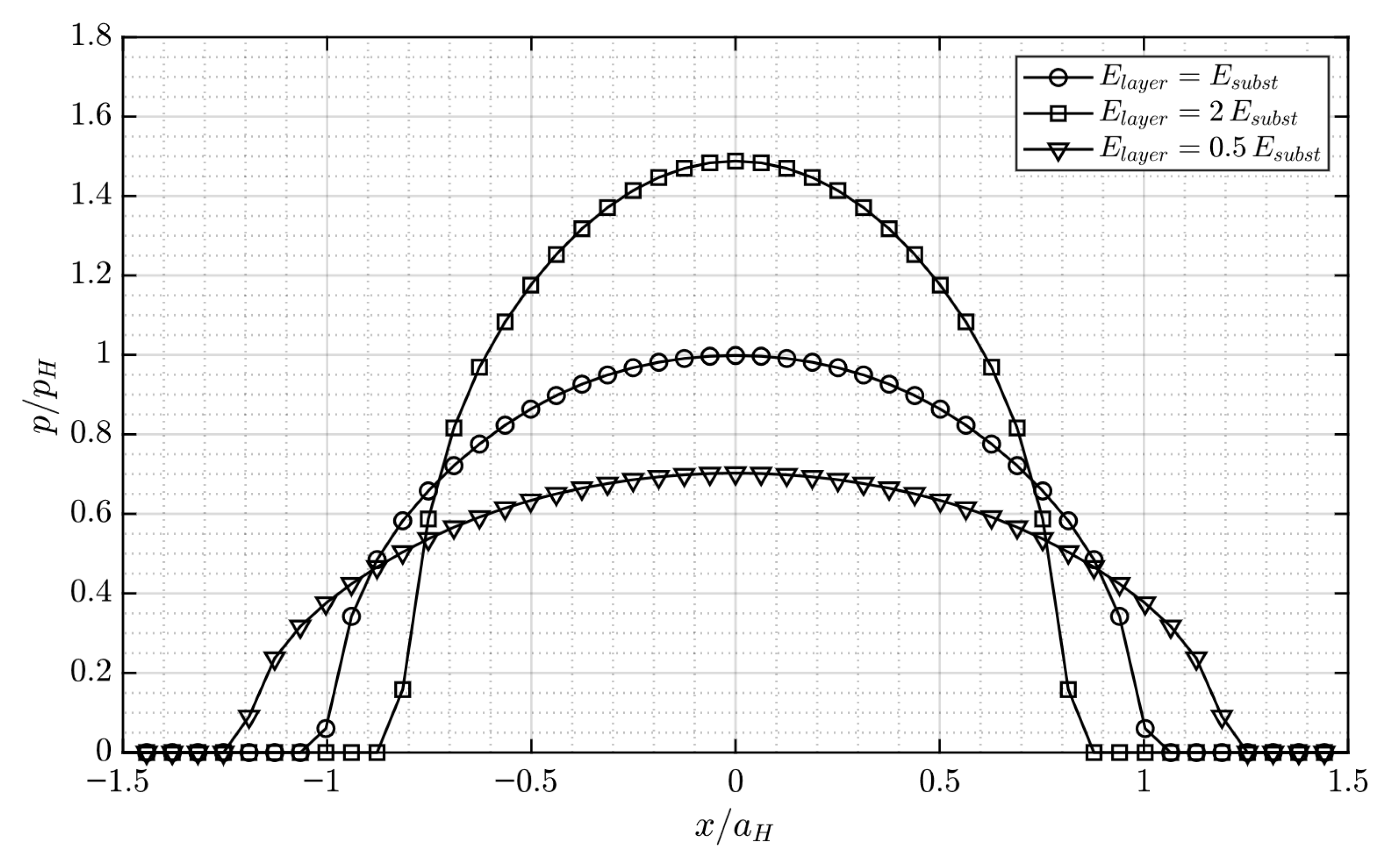
To verify the accuracy of the numerical implementation, the model was first compared with analytical Hertzian contact solutions for the homogeneous case. For this purpose, layer and substrate were assigned identical material properties, such that the layered half-space reduces to a homogeneous half-space. For the comparison, three elastic moduli (25 GPa, 102.1 GPa and 186.4 GPa) were simulated, each evaluated at three load levels (5 N, 50 N and 100 N) with and calculated according to Equation (11). The maximum contact pressure, maximum subsurface shear stress and the semi-axis widths of the pressure ellipse were evaluated and compared with the analytical calculations. Across all cases and metrics, the maximum relative deviation did not exceed 3% (see Appendix A Table A1). In addition, the simulated maximum pressure was qualitatively benchmarked against the results reported by WANG et al. [25]. Using the boundary conditions (see Table 1 in Ref. [25] and Table A2 in the Appendix A), the present model reproduced the trends in the maximum contact pressure for different layer-substrate combinations under frictionless conditions (see Figure 3a in Ref. [25] and Figure A1 in the Appendix A), indicating good qualitative agreement with the published results. These verification steps demonstrate that the numerical framework reproduces both analytical solutions as well as the published numerical results, providing a reliable basis for the subsequent parametric study.
The reported simulation parameters were found to provide consistent results for the verification cases and therefore retained for the subsequent parametric study.
3. Balancing Criterion
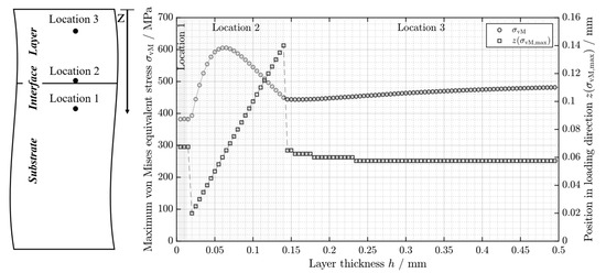
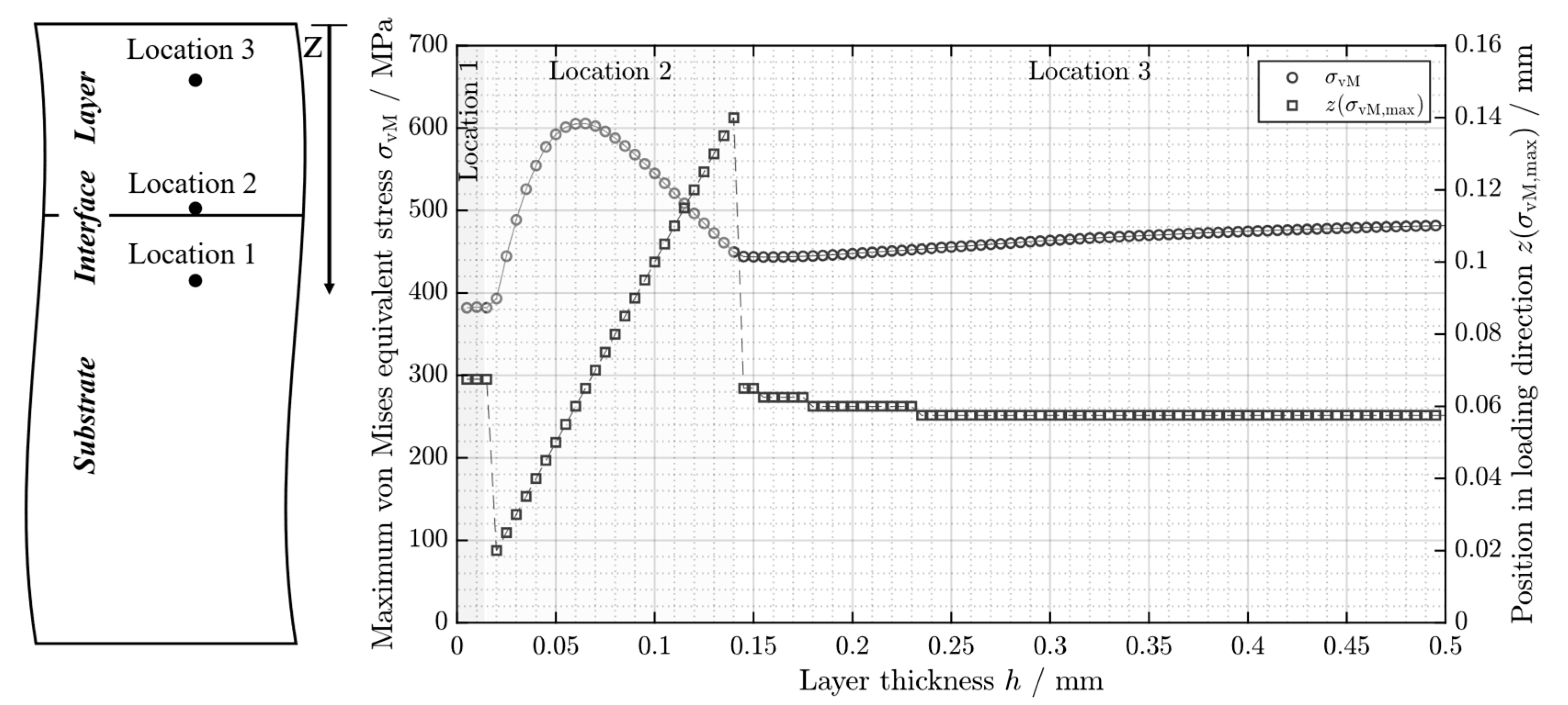
The load-carrying capacity of bi-layered contacts is primarily governed by the stress distribution within the two components. Variation in the layer thickness under constant load affects both the magnitude and location of the maximum equivalent stress within the surface layer and the substrate (see Figure 2 and Figure 3). For systems with a stiff layer and a compliant substrate, thin layer thickness typically results in high stress levels within the substrate (location 1). With increasing layer thickness, a larger proportion of the contact load is carried by the layer, which reduces the substrate stress but at the same time increases the layer stress. The maximum stress is now no longer located in the substrate but shifts to the layer directly at the interface (location 2). As the layer thickness increases further, the maximum equivalent stress decreases to a second minimum, now located within the layer near the surface (location 3). Beyond this point, the location and magnitude of the maximum equivalent stress approach the values corresponding to a homogeneous system consisting only of the solid layer material. Figure 2 illustrates this characteristic progression of stress and location with the transition of the critical stress zone from the substrate to the layer using the example of a layer-substrate system composed of the solid 17-4-PH and 316L. The transition from the critical stress zone from location 2 to location 3 represents a change in the load-bearing behaviour and forms the basis for the subsequent optimization and balancing criterion, which is restricted to the range of location 3. This restriction is adopted because the present balancing approach is formulated in terms of the admissible bulk stresses of layer and substrate. A consistent inclusion of location 2 would require an additional interface-specific failure criterion, for example with respect to interfacial debonding, which is beyond the scope of the present study.
Figure 2.
Maximum VON MISES stress and its corresponding position along the loading direction versus layer thickness for the solid layer-substrate system (right) and the corresponding generalized stress locations (left).
Figure 3.
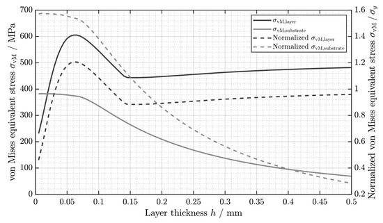
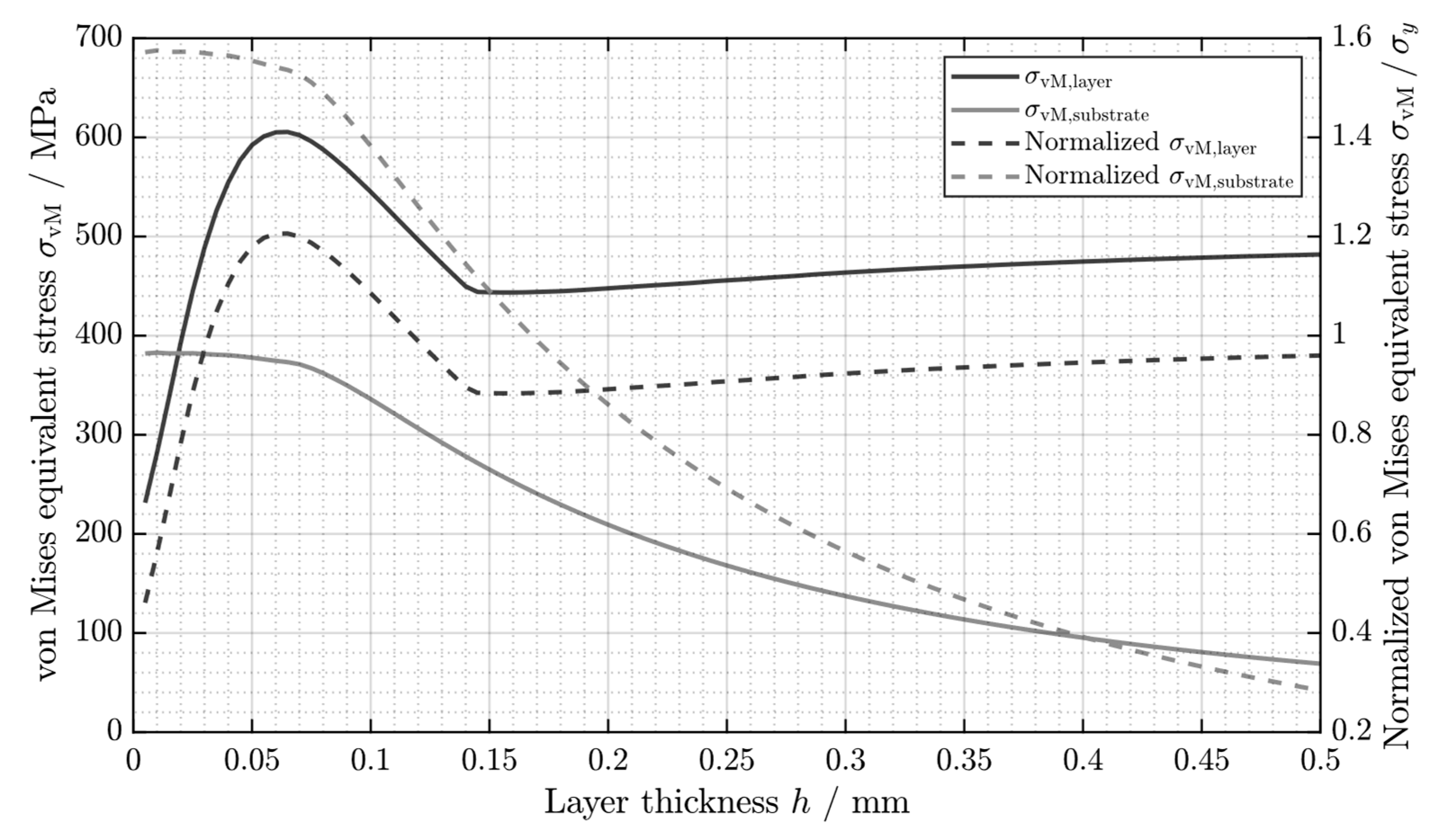
VON MISES stresses in layer and substrate (primary ordinate) and their normalized values (secondary ordinate) versus layer thickness for the solid layer-substrate system.
The balancing criterion is first introduced and described for this layer-substrate system of solid materials as a reference case. The subsequent extension to porous substrates is then carried out based on the described scaling laws and derived parameters (see Section 2.2.1) whilst applying the equivalent stress according to DESHPANDE and FLECK for the metal foam (see Equation (9)).
Figure 3 illustrates the corresponding stress distributions in the layer and substrate separately, both in the form of absolute values and normalized by their respective yield strengths. The normalized stress curves intersect at one point, where both materials are evenly loaded, therefore exhibiting equal utilization and neither unilaterally determines the limits of the system. This equalization of stress levels constitutes the physical basis for the balancing criterion formulated in the following.
The objective of this criterion is to optimize the layer thickness for a given load . For layer and substrate () a normalized utilization rate is defined with respect to a specified admissible limit as follows:
where denotes the respective equivalent stress. Thus describes a utilization rate of 100% and marks in this case the onset of yield in the respective material. The value of corresponds to a purely elastic state. The balanced utilization of both materials is achieved when layer and substrate simultaneously approach their respective admissible limits.
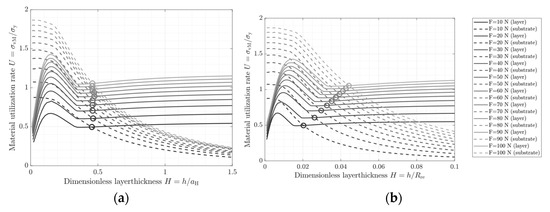
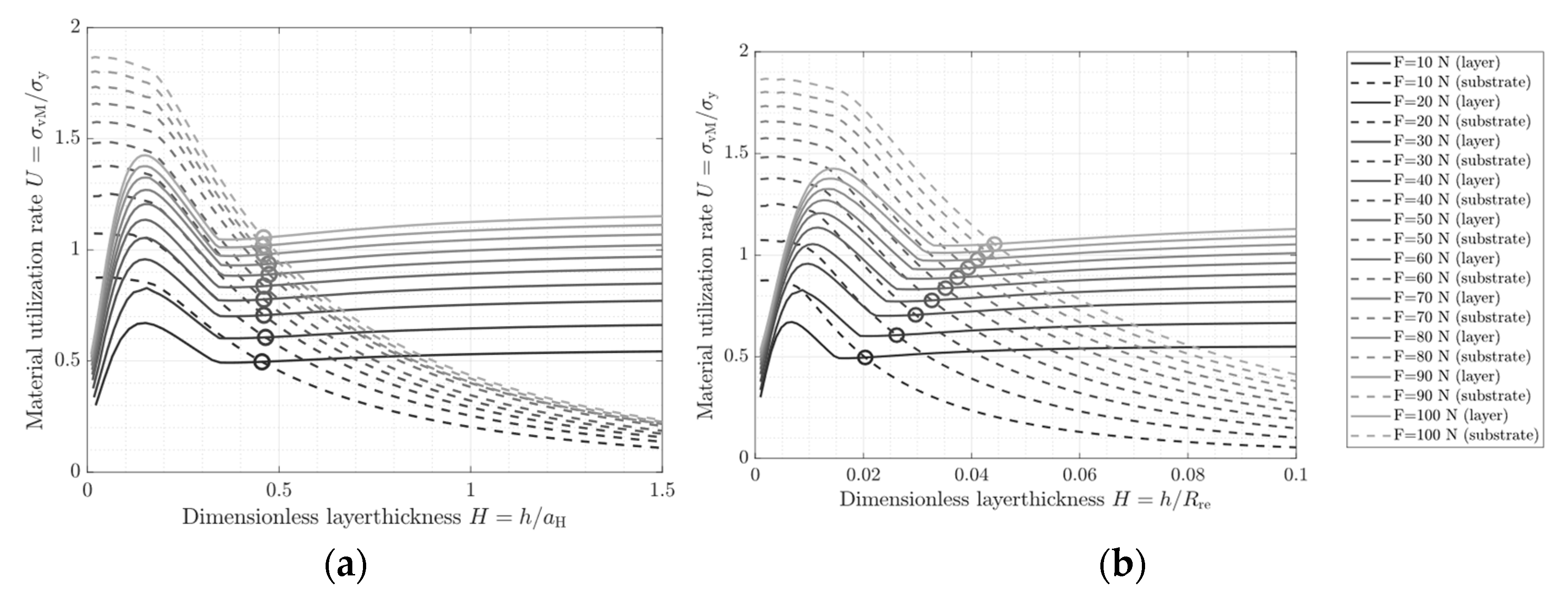
This condition defines the optimal layer thickness as the intersection point of the two utilization curves. For a given layer-substrate system and corresponding admissible limits, the balanced utilization can thus be determined for different load cases. Thereby, the layer thickness can be normalized in two ways, either with respect to the Hertzian contact semi-axis for a homogeneous system consisting only of the solid layer material (see Figure 4a) or with respect to the rolling element radius (see Figure 4b). While normalizing by is advantageous for contact-mechanical interpretation, since it relates the layer thickness directly to the contact zone, it does not provide a suitable independent design criterion. In this representation the balanced state is characterized by an approximately constant ratio over the considered load range, indicating that the optimal layer thickness scales with the load. This provides a compact description of the balanced state for a given load case but does not allow a design-oriented representation of the utilization rate. For this purpose, the layer thickness is normalized by the rolling element radius , which provides a fixed geometric reference and allows the balanced states to be represented by relations between optimal layer thickness and utilization rate for varying load cases. This yields a design-oriented representation in which, for a given load case, not only the required optimal layer thickness but also the corresponding material utilization can be determined directly.
Figure 4.
Material utilization of layer and substrate as a function of the dimensionless layer thickness: (a) Normalized by the Hertzian contact semi-axis . (b) Normalized via the rolling element radius .
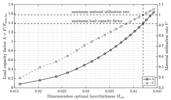
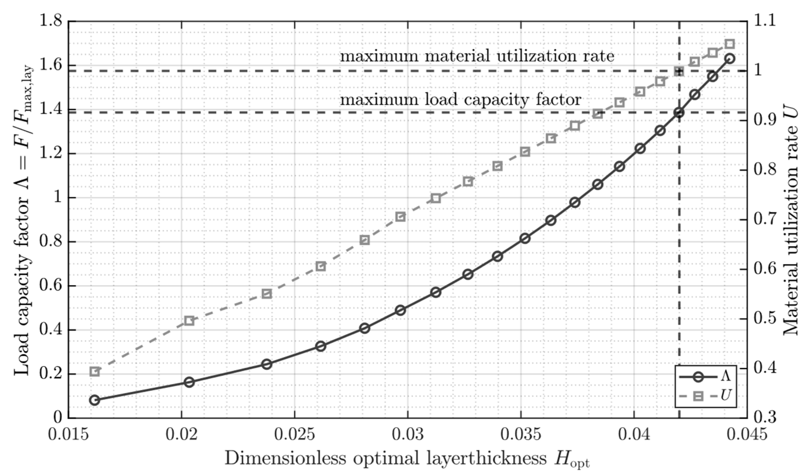
The optimal dimensionless layer thickness denotes the state in which neither component is disproportionately loaded. The associated load and utilization values are shown in Figure 5, which is directly obtained from the intersection points identified in Figure 4b. For each load case the corresponding intersection points deliver the optimal dimensionless layer thickness together with the equal utilization value (see Equation (13)). The same load case is then represented by the load capacity factor , which is defined as the applied load normalized by the admissible limit load of 61.3 N corresponding to a homogeneous system consisting only of the solid layer material (determined from the load at which the VON MISES stress first reaches the yield strength in the homogeneous reference system).
Figure 5.
Load capacity factor and utilization rate as functions of dimensionless optimal layer thickness.
Thus, Figure 4b represents the determination of the balanced operating point for each individual load case, whereas Figure 5 represents the condensed design relation obtained from the complete set of balanced operating points. For a given load case, the corresponding load capacity factor can be projected onto the curve, from which the associated optimal layer thickness and utilization rate are obtained by vertically projecting this intersection point onto the abscissa and curve. The reference lines shown in Figure 5 exemplify this procedure for the limiting case of maximum material utilization marking the attainable limiting state for the given material combination.
The progression of the utilization rate can be described by a linear function, whereas the load capacity factor follows a cubic relationship.
Utilization rate and load capacity factor are not unrelated to each other but depend on the dimensionless optimal layer thickness . Accordingly, the two parameters can be related to each other:
The optimization characteristic of the layer-substrate system can therefore be reduced to two scalar parameters, which are summarized in the scaling factor .
4. Results
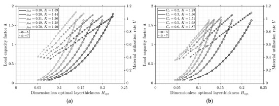
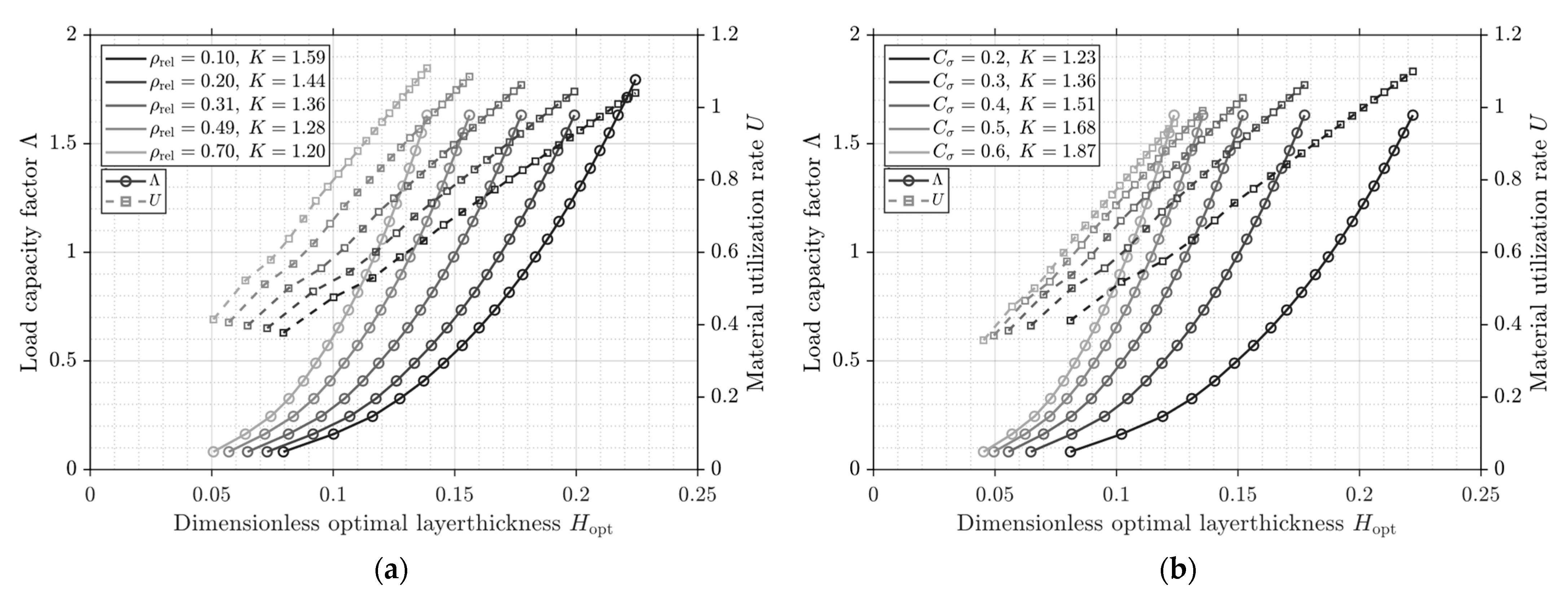
To examine a layer-substrate system with porous substrate material, the balancing approach introduced in Section 3 was applied to the simulation results obtained from the aforementioned variations in the elastic modulus and the coefficient as well as the equivalent stress for the porous material calculated according to DESHPANDE and FLECK (see Equation (9)). Figure 6 depicts the progression of the utilization rate and the load capacity factor for selected parameter combinations. The families of curves demonstrate that the optimal layer thickness is governed by the porosity-dependent substrate behaviour. Variations in the substrate properties result in different coefficients and , while the fundamental forms of the linear and cubic relationships remain unchanged. In particular, decreasing the substrate stiffness and higher admissible loads shift both the value of and the maximum attainable load amplification.
Figure 6.
Load capacity factors and utilization rates for: (a) and selected relative densities; (b) and selected .
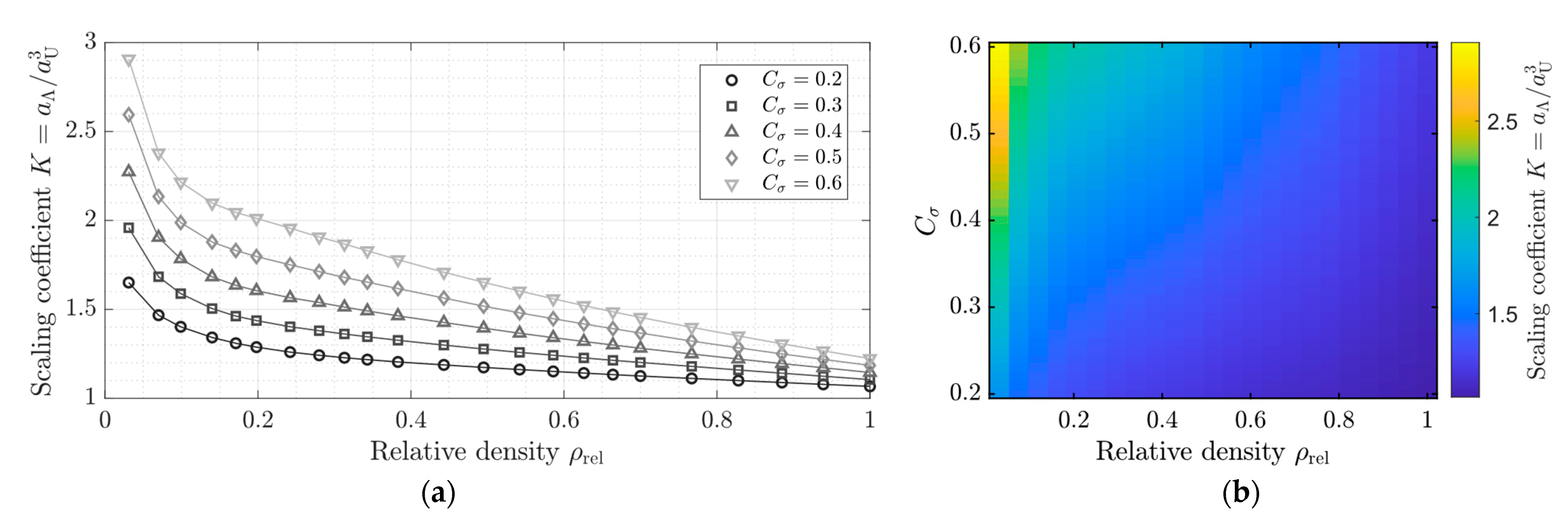
The scaling factor is therefore not only dependent on a single parameter but must be expressed as a function of relative density and . Figure 7 presents as a function of for selected values of , as well as a corresponding heat map representation covering the entire investigated area. Owing to the relationship between load capacity factor and utilization rate (see Equation (17)), with this representation of the scaling factor corresponds to the maximum achievable load amplification of the layer-substrate system relative to the corresponding homogeneous system consisting only of the solid layer material. The heat map thus depicts the load amplification at maximum material utilization for the entire parameter range investigated.
Figure 7.
Scaling factor : (a) As a function of the relative density for selected . (b) Corresponding heat map for the investigated parameter space.
To describe the two-dimensional dependence of in a compact manner, a separable modelling approach is proposed in which the relationship is decomposed into two contributing factors. A scaling component, describing the dependence on and a density-dependent master curve , which represents the variation over the relative density.
For the scaling component, a reference value is first determined from the simulated data points for each strength level defined by . This reference value serves to characterize the global scaling level of the respective parameter set.
This definition is introduced as a formal offset to facilitate the separable representation in the following Equations (20)–(22). The pair () should not be interpreted as a physically porous material state but rather as a virtual reference used to parameterise the substrate response. After accounting for this offset
the remaining dependence is analyzed using a rank-1 singular value decomposition, yielding an approximation of the form
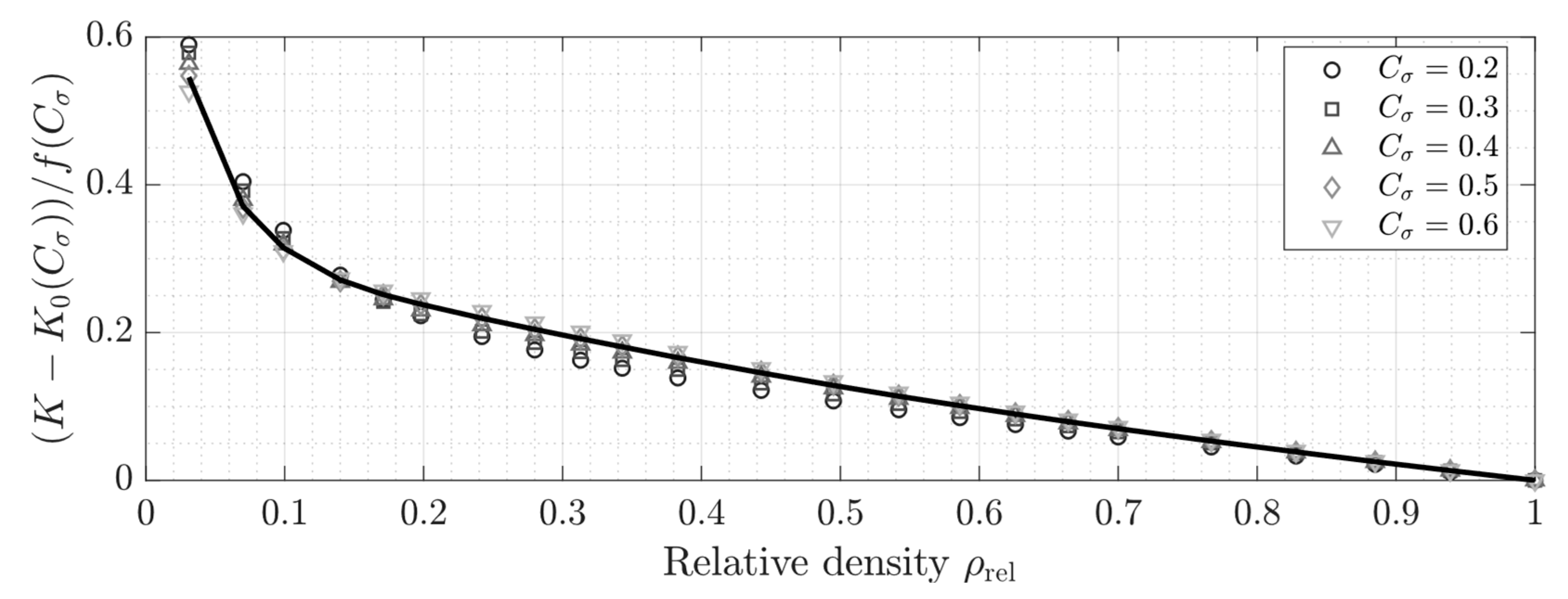
where represents the scaling function and denotes the universal master curve. After the division of all data sets by
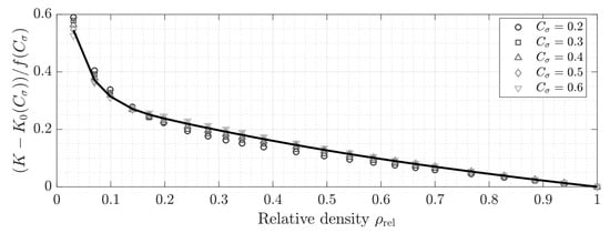
the original points converge onto the corresponding master function (see Figure 8).
Figure 8.
Normalized scaling factor versus relative density for selected .
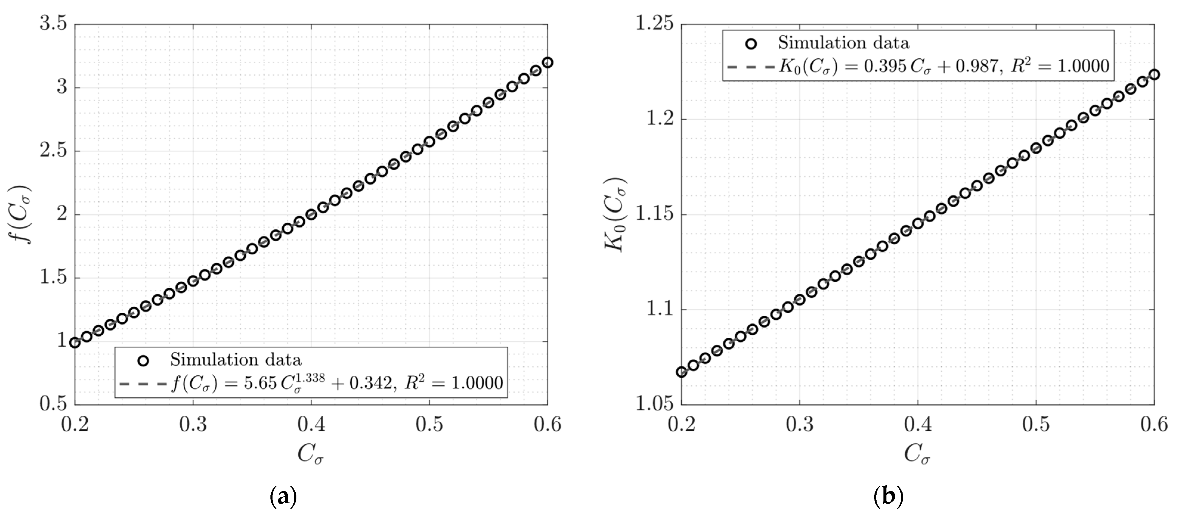
The scaling function and the reference value can be described by the following relations with coefficients of determination .
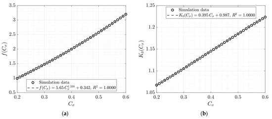
The data calculated for and are shown with their corresponding fit functions in Figure 9.
Figure 9.
Simulated data points and their respective fit: (a) Scaling function . (b) Reference value .
The master curve can likewise be represented by a fitted function with a coefficient of determination , given by:
Using Equations (22)–(25), the scaling factor can thus be expressed by an empirical representation of the simulated parameter range as follows:
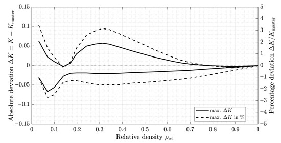
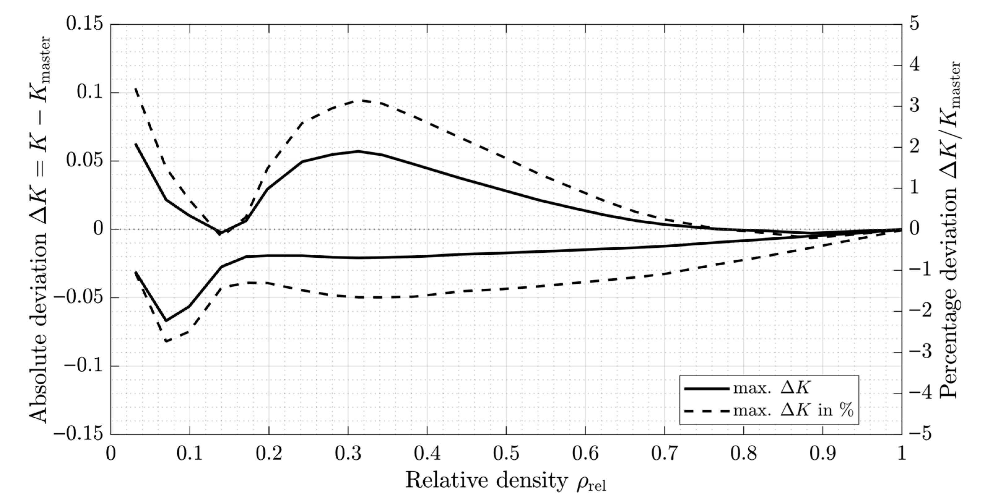
Hence the dataset is generated by deterministic numerical simulations with negligible noise; high coefficients of determination are expected and are therefore not used as the sole indicator of quality. Instead, the accuracy of the compact representation is quantified by the maximum relative deviation between the fitted model and the simulated results over the investigated parameter range, which remains below 3.5% (see Figure 10). This deviation directly influences the calculation of the load capacity factor and, in accordance with Equation (17), affects the estimation of the utilization rate through a cubic root dependence.
Figure 10.
Deviation-simulated scaling factors K and its empirical representation .
The empirical description must be read as a compact representation of the numerical results within the investigated parameter space. It should therefore be interpreted as an interpolation tool for the considered range rather than a universal scaling law. The presented results are based on yielding as the admissible limit and therefore do not constitute a fatigue-life model, but rather a yield-based implementation of the general framework. The underlying balanced utilization concept can, in principle, also be formulated with other application-specific admissible limits, for example fatigue-related criteria. Since fatigue behaviour is governed by the local stress state, the present results can, in this context, be interpreted as a mechanical assessment of the load sharing between dense layer and porous substrate.
5. Discussion
The results presented are consistent with the established findings for coated systems. Previous studies have shown that critical stress locations and associated stress fields in layered contacts exhibit non-monotonic progressions with increasing coating thickness. The observed shift in the maximum equivalent stress between substrate, interface and layer is in qualitative agreement with these findings and extends the concept to porous substrates. In contrast to classical bi-layer systems composed of independently selectable bulk materials, the porous substrate considered here represents a porosity-coupled material system. Stiffness and admissible stress are not independent parameters but are linked through porosity-dependent scaling laws. As a consequence, the design problem extends beyond layer thickness optimization to coupled optimization of layer thickness and relative density. The load-bearing behaviour is therefore not only governed by geometric scaling but also by the intrinsic coupling of elastic and strength properties imposed by the cellular architecture of the foam.
The proposed methodology is based on established approaches for analyzing layered systems but adapts them to structures with a porous core and introduces a balancing criterion for continuous material utilization. Rather than primarily identifying the initial occurrence of first yielding, the methodology shown goes beyond a limit-state analysis and allows the system to be evaluated for a wide load range by bringing both system components equally close to their permissible stress limits. In doing so, an explicit relationship between material parameters and layer thickness is described, which also includes partial load conditions as a design space. This continuous utilization approach represents an extension of existing concepts and allows porosity-dependent material laws to be directly converted into mechanical design parameters.
Within the investigated parameter range, the utilization rate scales linearly with layer thickness while the load capacity factor follows a cubic relationship. This functional form was observed for all considered combinations of elastic modulus and admissible substrate strength, where variations in these parameters only affect the proportionality coefficients but not the observed exponents. Accordingly, the influence of the material parameters within the studied domain can be represented through the prefactors and .
The scaling factor introduced in this work not only links the load capacity factor and utilization rate but directly quantifies the maximum load amplification conditions under balanced utilization compared to a homogeneous system consisting only of the solid layer material. Thus provides a compact performance measure for the system and can be interpreted as a descriptor of the efficiency gain achieved by introducing a compliant porous substrate as a support for a stiff surface. It therefore serves as a comparative metric for different substrate architectures and material combinations, independent of the absolute load. The simulations thereby indicate a possible load amplification of up to 190%. Furthermore, the simulation results were approximated by an empirical representation that separates the dependence on relative density and strength scaling. The proposed empirical representation agrees with the numerically determined values of within a maximum relative deviation of around 3.5%. This deviation is substantively smaller than the variation induced by changes in relative density and strength scaling. However, the empirical representation should be regarded as a compact interpolation of the simulated data and is consequently limited to the investigated parameter space, and extrapolation should be avoided. Nevertheless, such an empirical description of the modelled system can be used to estimate the scaling factor, provided that the quantified deviations are taken into account.
In practical terms the balancing criterion establishes a direct design relationship between layer thickness, applied load and material utilization. For a given target load, the methodology allows the balanced layer thickness and utilization rate to be determined such that the layer and substrate exhibit the same relative strength reserve with respect to their admissible limits. Conversely, for a prescribed layer thickness, the corresponding balanced utilization and admissible load-carrying capacity can be assessed. The approach therefore provides not only a means of evaluating layered systems, but also a design-oriented framework for selecting layer thickness and substrate properties on the basis of the given operating state.
The present investigation focuses on the onset of yielding as a design criterion for layered systems with porous substrates. While bearings typically fail due to other mechanisms, such as fatigue, the identification of the yield limit provides a useful indicator for admissible load levels and for assessing the influence of substrate porosity on the resulting stress distribution. Furthermore, the use of the utilization rate as a measure of the remaining load-carrying capacity allows the proposed approach to be extended to lower load levels by evaluating the corresponding reduction in material utilization. Although the numerical investigation is demonstrated for the example of a thrust ball bearing, the proposed balancing approach is not restricted to this specific configuration and can in principle be applied to other layered contact systems with porous substrates.
It should be noted that the present study represents a numerical design investigation and that experimental validation is beyond the scope of the present publication. Accordingly, the results must be interpreted within the framework of the adopted modelling assumptions. The balancing criterion and presented scaling relations are evaluated within the regime in which the critical stress is located in the layer near the surface, as introduced in Section 3. The validity of as a scaling factor and performance criteria is therefore tied to this optimization domain. Further work should address its applicability and any adjustments that may be necessary for other domains. Additionally, the presented load amplification rates also result from variation in the coefficient while maintaining the adopted scaling for the elastic modulus. Reported values of in the literature exhibit considerable variation. The quantitative amplification should therefore be interpreted within the context of the assumed scaling parameters. Since the empirical representation is based on the GIBSON–ASHBY scaling laws of porous materials, the quantitative prediction is inherently linked to the assumed exponents and proportionality coefficients. However, the systematic variation of demonstrates the sensitivity of the design criteria to foam-specific parameters and provides a transferable method once experimentally determined scaling data is available. Furthermore, the porous structure was modelled as a homogeneous material. Local microstructural effects such as defects and anisotropy are therefore not resolved. Likewise, potential imperfections in the interface between layer and substrate are not considered. The assumption of perfect bonding between layer and substrate therefore represents an upper-bound scenario for load transfer across the interface. Future work should thus investigate the influence of non-homogeneous conditions, the sensitivity of the results to alternative scaling assumptions and extend the approach to frictional contact configurations. In addition, future studies should address the experimental validation, for example by spherical indentation tests on layered dense-porous systems with varying layer thickness and substrate porosity, or by rolling contact experiments on component-near specimens to examine whether the predicted trends are reproduced experimentally.
6. Conclusions
In this contribution, a systematic methodology was developed for the assessment of layer-substrate systems with a dense solid surface and a porous substrate based on a criterion of balanced material utilization. A design objective was formulated in which both components are driven towards their stress limits without under- or over-utilization of either material. On this basis, the influence of foam-specific material parameters on the admissible load was quantified and their relationship to load-carrying capacity was described empirically. The main conclusions of the presented work can be summarized as follows:
- It was shown that, for suitable combinations, layered systems can sustain higher loads than their counterparts comprising only the layer material. This observation is consistent with findings reported in the literature for coated contacts, where load amplification effects have also been identified.
- A dimensionless utilization parameter was introduced to characterize the stress state relative to material-dependent admissible limits as well as a load capacity factor, which describes the applied load relative to the admissible load of a homogeneous system consisting only of the dense layer material.
- Through a defined scaling factor , which combines the coupled influence of relative density and the foam parameter , the utilization rate was linked to the admissible load and layer thickness. Furthermore, under balanced material utilization represents the maximum achievable load amplification of the layered system relative to the homogeneous reference case.
- The utilization rate thereby serves both as an evaluation metric as well as a design criterion. For a given target utilization, the corresponding load-carrying capacity and required layer thickness can be determined. The methodology thus provides a transition from material-dependent properties to concrete design parameters, enabling a systematic dimensioning of layered systems with a porous substrate.
The present work extends the existing approaches in the literature by formulating an explicit design framework for layer-substrate systems with a porous base through the introduction of the scaling factor and utilization rate. The proposed approach provides a transferable methodology for integrating porosity-dependent material models into the mechanical design of layered structures, given appropriate knowledge of the mechanical properties and scaling laws of the system. Consequently, the conclusions are subject to the presented modelling assumptions of perfect bonding between layer and substrate, representing an idealized upper-bound scenario for load transfer. The observed scaling laws must therefore be interpreted within the model assumptions and investigated parameter range. Its applicability to systems exhibiting interfacial inhomogeneities as well as interfacial defects should therefore be addressed in future work.
Author Contributions
Conceptualization, O.G. and S.G.; methodology, O.G. and S.G.; software, O.G. and S.P.; validation, O.G.; formal analysis, O.G.; resources, O.K.; data curation, O.G.; writing—original draft preparation, O.G.; writing—review and editing, all authors; visualization, O.G.; supervision, O.K. and S.G.; project administration, O.K. and S.G.; funding acquisition, O.K. and S.T. All authors have read and agreed to the published version of the manuscript.
Funding
Funded by the Deutsche Forschungsgemeinschaft (DFG, German Research Foundation)—Project-ID 511263698—TRR 375.
Data Availability Statement
Dataset available from the authors on reasonable request due to their ongoing use in current research projects.
Conflicts of Interest
The authors declare no conflicts of interest.
Abbreviations
The following abbreviations are used in this manuscript:
| AM | Additive manufacturing |
| CAD | Computer-aided design |
| CRC | Collaborative Research Centre |
| FE | Finite element simulations |
| FT | Fourier transform |
| ~ | |
| HyPo | Hybrid porous materials/structures |
| vM | Von Mises |
| WAAM | Wire arc additive manufacturing process |
Nomenclature
The following symbols are used in this manuscript:
| Symbol | Unit | Description |
| - | Coefficients of the Papkovich–Neuber potentials | |
| mm | Semi-axis of the contact ellipse in x-direction | |
| mm | Hertzian semi-axis of the contact ellipse in x-direction (analytical solution for mono-material systems) | |
| - | Scaling coefficients of the load capacity factor and utilization rate | |
| mm | Semi-axis of the contact ellipse in y-direction | |
| mm | Hertzian semi-axis of the contact ellipse in y-direction (analytical solution for mono-material systems) | |
| - | Scaling constant (foam model) | |
| mm | Rolling element diameter | |
| GPa | Young’s modulus | |
| N | Normal load applied to one rolling element | |
| GPa | Shear modulus | |
| - | Density-dependent master function | |
| - | Dimensionless layer thickness | |
| mm | Layer thickness | |
| - | 1, 2 and 3 corresponding to the Cartesian coordinates x, y and z | |
| - | Scaling factor | |
| - | Reference value of the scaling factor | |
| - | ) | |
| 1/mm | frequency-domain counterpart of the coordinates x and y | |
| - | Scaling exponent (foam model) | |
| mm | Rolling element radius | |
| mm | Raceway radius | |
| - | Material utilization rate | |
| N | Applied bearing load | |
| mm | Surface displacement | |
| 1/mm | Wavenumber (frequency domain) | |
| - | Pressure sensitivity parameter (Deshpande–Fleck yield criterion) | |
| - | Kronecker delta | |
| - | Load capacity factor | |
| - | Poisson’s ratio and plastic Poisson’s ratio | |
| kg/m3 | Density of the dense and foam material | |
| - | Relative density | |
| MPa | Yield strength, Compression strength | |
| MPa | Equivalent stress of layer and substrate | |
| MPa | Hydrostatic stress component, deviatoric stress component expressed by the von Mises, yield criterion proposed by Deshpande and Fleck | |
| - | Porosity | |
| - | Papkovich–Neuber potentials |
Appendix A
Table A1.
Comparison between numerical model and analytical Hertzian contact solution for the homogeneous half-space (identical layer and substrate properties).
Table A2.
Simulation parameters used for the comparison with the results reported by WANG et al. [25].
Figure A1.
Normalized contact pressure distribution along the x-direction for different elastic modulus ratios (parameters acc. to Table A2).
References
- Jakovljević, S.; Landek, D. Special Issue: Tribological Coatings—Properties, Mechanisms, and Applications in Surface Engineering. Coatings 2023, 13, 451. [Google Scholar] [CrossRef] [Scilit]
- Wang, X.; Zhao, W.; Shi, T.; Cheng, L.; Hu, S.; Zhou, C.; Cui, L.; Li, N.; Liaw, P.K. A Review on Tribological Wear and Corrosion Resistance of Surface Coatings on Steel Substrates. Coatings 2025, 15, 1314. [Google Scholar] [CrossRef] [Scilit]
- Matthews, A.; Rickerby, D. Advanced Surface Coatings a Handbook of Surface Engineering; Springer: New York, NY, USA, 1991. [Google Scholar]
- Körner, C.; Singer, R.F. Processing of Metal Foams—Challenges and Opportunities. Adv. Eng. Mater. 2000, 2, 159–165. [Google Scholar] [CrossRef]
- Grutza, O.; Stiemcke, Y.; Bähr, M.; Warth, A.; Teutsch, R.; Steiner-Stark, J.; Koch, O.; Thielen, S. Model-based assessment of the cooling potential of additively manufactured shafts considering the ageing-related service life of radial shaft seals. Prod. Eng. 2025, 20, 21. [Google Scholar] [CrossRef] [Scilit]
- Chen, D.; Gao, K.; Yang, J.; Zhang, L. Functionally graded porous structures: Analyses, performances, and applications—A Review. Thin-Walled Struct. 2023, 191, 111046. [Google Scholar] [CrossRef] [Scilit]
- Nazir, A.; Gokcekaya, O.; Billah, K.M.M.; Ertugrul, O.; Jiang, J.; Sun, J.; Hussain, S. Multi-material additive manufacturing: A systematic review of design, properties, applications, challenges, and 3D printing of materials and cellular metamaterials. Mater. Des. 2023, 226, 111661. [Google Scholar] [CrossRef] [Scilit]
- Aurich, J.C. TRR 375: Multifunctional High Performance Components Made from Hybrid Porous Materials, 2024. Available online: https://gepris.dfg.de/gepris/projekt/511263698 (accessed on 17 March 2026).
- Platz, J.; Bachert, L.; Steiner-Stark, J.; Kirsch, B.; Aurich, J.C. Manufacturing of a solid skin on porous metals using Directed Energy Deposition. Procedia CIRP 2025, 137, 52–57. [Google Scholar] [CrossRef] [Scilit]
- Platz, J.; Steiner-Stark, J.; Bachert, L.; Aurich, J.C. Directed energy deposition on porous metal substrates: Interfacial characteristics and process strategies for joining porous and dense structures. Prod. Eng. 2026, 20, 54. [Google Scholar] [CrossRef] [Scilit]
- Platz, J.; Steiner-Stark, J.; Kirsch, B.; Aurich, J.C. Fertigung funktional gradierter Materialien auf porösen Metallen durch Laserauftragschweißen. Z. Wirtsch. Fabr. 2024, 119, 515–519. [Google Scholar] [CrossRef] [Scilit]
- Faßhauer, M.; Maier, H.J.; Hassel, T. Systematic generation of pores in AlSi10Mg components using specific shielding gas conditions in the GMAW-WAAM process. Prod. Eng. 2026, 20, 40. [Google Scholar] [CrossRef] [Scilit]
- Faßhauer, M.; Maier, H.; Hassel, T. Influence of the manufacturing sequence on the microstructure and mechanical properties of hybrid 316L and 17-4 PH walls manufactured with DED-Arc/M. In Tagungsband 6. Symposium Materialtechnik: 20. bis 21. Februar 2025; Shaker Verlag: Aachen, Germany, 2025. [Google Scholar] [CrossRef]
- Banhart, J. Manufacture, characterisation and application of cellular metals and metal foams. Prog. Mater. Sci. 2001, 46, 559–632. [Google Scholar] [CrossRef] [Scilit]
- Goltsberg, R.; Etsion, I.; Davidi, G. The onset of plastic yielding in a coated sphere compressed by a rigid flat. Wear 2011, 271, 2968–2977. [Google Scholar] [CrossRef] [Scilit]
- Goltsberg, R.; Etsion, I. Contact area and maximum equivalent stress in elastic spherical contact with thin hard coating. Tribol. Int. 2016, 93, 289–296. [Google Scholar] [CrossRef] [Scilit]
- Ronen, S.; Goltsberg, R.; Etsion, I. A comparison of stick and slip contact conditions for a coated sphere compressed by a rigid flat. Friction 2017, 5, 326–338. [Google Scholar] [CrossRef] [Scilit]
- Chen, Z.; Goltsberg, R.; Etsion, I. Yield modes in a coated spherical contact. Tribol. Int. 2018, 120, 309–316. [Google Scholar] [CrossRef] [Scilit]
- Burmister, D.M. The General Theory of Stresses and Displacements in Layered Systems. I. J. Appl. Phys. 1945, 16, 89–94. [Google Scholar] [CrossRef] [Scilit]
- Chen, W.T. Computation of stresses and displacements in a layered elastic medium. Int. J. Eng. Sci. 1971, 9, 775–800. [Google Scholar] [CrossRef] [Scilit]
- Chen, W.T.; Engel, P.A. Impact and contact stress analysis in multilayer media. Int. J. Solids Struct. 1972, 8, 1257–1281. [Google Scholar] [CrossRef] [Scilit]
- O’Sullivan, T.C.; King, R.B. Sliding Contact Stress Field Due to a Spherical Indenter on a Layered Elastic Half-Space. J. Tribol. 1988, 110, 235–240. [Google Scholar] [CrossRef] [Scilit]
- Liu, S.; Wang, Q.; Liu, G. A versatile method of discrete convolution and FFT (DC-FFT) for contact analyses. Wear 2000, 243, 101–111. [Google Scholar] [CrossRef] [Scilit]
- Polonsky, I.A.; Keer, L.M. A numerical method for solving rough contact problems based on the multi-level multi-summation and conjugate gradient techniques. Wear 1999, 231, 206–219. [Google Scholar] [CrossRef] [Scilit]
- Wang, Z.-J.; Wang, W.-Z.; Wang, H.; Zhu, D.; Hu, Y.-Z. Partial Slip Contact Analysis on Three-Dimensional Elastic Layered Half Space. J. Tribol. 2010, 132, 021403. [Google Scholar] [CrossRef] [Scilit]
- Yu, C.; Wang, Z.; Wang, Q.J. Analytical frequency response functions for contact of multilayered materials. Mech. Mater. 2014, 76, 102–120. [Google Scholar] [CrossRef] [Scilit]
- Wang, T.; Wang, L.; Gu, L.; Zheng, D. Stress analysis of elastic coated solids in point contact. Tribol. Int. 2015, 86, 52–61. [Google Scholar] [CrossRef] [Scilit]
- Yu, C.; Wang, Z.; Liu, G.; Keer, L.M.; Wang, Q.J. Maximum von Mises Stress and Its Location in Trilayer Materials in Contact. J. Tribol 2016, 138, 041402. [Google Scholar] [CrossRef] [Scilit]
- Spinu, S. Maximum von Mises Stress in the Sliding Contact of Coated Bodies. Tribol. Ind. 2019, 41, 242–253. [Google Scholar] [CrossRef] [Scilit]
- Ashby, M.F. (Ed.) Metal Foams; Butterworth-Heinemann: Boston, MA, USA, 2000. [Google Scholar]
- Nikas, G.K. (Ed.) Recent Developments in Wear Prevention, Friction and Lubrication; Research Signpost: Kerala, India, 2010. [Google Scholar]
- Deshpande, V.S.; Fleck, N.A. Isotropic constitutive models for metallic foams. J. Mech. Phys. Solids 2000, 48, 1253–1283. [Google Scholar] [CrossRef] [Scilit]
- Zhuang, W.; Sun, J.; Xie, D. Modified Deshpande–Fleck Model considering a Variable Plasticity Poisson’s Ratio and a Variable Ellipticity. Adv. Mater. Sci. Eng. 2022, 2022, 9235106. [Google Scholar] [CrossRef] [Scilit]
- Gibson, L.J.; Ashby, M.F. Cellular Solids, 2nd ed.; 1st Paperback ed. (with Corr.) Transferred to Digital Printing ed.; Cambridge University Press: Cambridge, UK, 2001. [Google Scholar]
- Deshpande, V.S.; Ashby, M.F.; Fleck, N.A. Foam topology: Bending versus stretching dominated architectures. Acta Mater. 2001, 49, 1035–1040. [Google Scholar] [CrossRef] [Scilit]
- Jain, H.; Gupta, G.; Kumar, R.; Mondal, D.P. Microstructure and compressive deformation behavior of SS foam made through evaporation of urea as space holder. Mater. Chem. Phys. 2019, 223, 737–744. [Google Scholar] [CrossRef] [Scilit]
- Jain, H.; Gupta, G.; Mondal, D.P.; Srivastava, A.K.; Pandey, A.; Srivastava, S.k.; Kumar, R. Effect of particle shape on microstructure and compressive response of 316L SS foam by space holder technique. Mater. Chem. Phys. 2021, 271, 124924. [Google Scholar] [CrossRef] [Scilit]
- Mondal, D.P.; Jain, H.; Das, S.; Jha, A.K. Stainless steel foams made through powder metallurgy route using NH4HCO3 as space holder. Mater. Des. 2015, 88, 430–437. [Google Scholar] [CrossRef] [Scilit]
- Kato, K.; Yamamoto, A.; Ochiai, S.; Wada, M.; Daigo, Y.; Kita, K.; Omori, K. Cytocompatibility and mechanical properties of novel porous 316L stainless steel. Mater. Sci. Eng. C 2013, 33, 2736–2743. [Google Scholar] [CrossRef] [Scilit] [PubMed]
- Roberts, A.P.; Garboczi, E.J. Elastic properties of model random three-dimensional open-cell solids. J. Mech. Phys. Solids 2002, 50, 33–55. [Google Scholar] [CrossRef] [Scilit]
- Hoffmann, M.A.; Blinn, B.; Beck, T.; Faßhauer, M.; Hassel, T. Analyse der prozessinduzierten Mikrostruktur-Eigenschafts-Beziehung in einer WAAM-gefertigten Materialgradierung. In Proceedings of the DVM-Arbeitskreis Additiv Gefertigte Bauteile und Strukturen, Berlin, Germany, 4–5 November 2025. [Google Scholar] [CrossRef]
- SKF. 51208 Single Direction Thrust Ball Bearing. Available online: https://www.skf.com/at/products/rolling-bearings/ball-bearings/thrust-ball-bearings/productid-51208 (accessed on 17 March 2026).
- DIN 26281:2010-11; Rolling Bearings-Methods for Calculating the Modified Reference Rating LIFE for Universally Loaded Bearings. German Institute for Standardisation: Berlin, Germany, 2010.

Disclaimer/Publisher’s Note: The statements, opinions and data contained in all publications are solely those of the individual author(s) and contributor(s) and not of MDPI and/or the editor(s). MDPI and/or the editor(s) disclaim responsibility for any injury to people or property resulting from any ideas, methods, instructions or products referred to in the content. |
© 2026 by the authors. Licensee MDPI, Basel, Switzerland. This article is an open access article distributed under the terms and conditions of the Creative Commons Attribution (CC BY) license.