


Abstract
Organic coatings are used as one of the most effective strategies for the corrosion protection of metals. Nowadays, due to environmental regulations, the use of water-based coatings has become essential compared to solvent-based ones. However, their application to magnesium alloys remains largely unexplored due to their high reactivity with water. In the present work, a phosphate-functionalized waterborne binder is applied to AZ31B magnesium alloy. The surface has been modified by four different pre-treatments, respectively: (i) mechanical grinding, (ii) pickling, (iii) conventional conversion treatment, and (iv) a novel conversion treatment based on layered double hydroxides (LDH). The most promising pre-treatments are selected to explore their synergy with a biobased waterborne binder, containing CeO2 nanoparticles as a corrosion inhibitor. The morphology and composition of the different systems are studied, prior to and after corrosion tests in NaCl solution, by scanning electron microscopy (SEM) and energy-dispersive X-ray spectroscopy (EDS). Results obtained by electrochemical impedance spectroscopy (EIS) in NaCl solution have revealed not only that LDH performs better than the conventional conversion treatment but also the synergy between LDH pre-treatment and CeO2 nanoparticles when two organic layers are used.
1. Introduction
Magnesium alloys are widely used due to their biocompatibility, moderate ductility, and high specific strength [1,2,3,4]. However, their poor corrosion resistance is a major limitation [5,6,7], necessitating effective surface protection [8,9]. A variety of surface treatments are employed, including mechanical (e.g., blasting, grinding) [10], chemical conversion coatings (CC) [11,12], or plasma electrolytic oxidation (PEO) [13,14], among others. In general, mechanical treatments (e.g., grinding, blasting, etc.) are not enough; additional chemical ones are required.
CC offer a cost-effective, fast, and simple method to enhance corrosion resistance and improve the adhesion of organic coatings [15]. Chromate conversion coatings (CCC), despite their excellent corrosion resistance [16], have been banned due to the carcinogenic and toxic properties of Cr(VI)-based baths [17,18]. As a result, alternative treatments such as phosphate-based coatings [19,20], permanganates [21,22], rare earth elements [23,24], and Cr(III)-based treatments [25] have gained prominence. Recently, layered double hydroxides (LDH) have been explored not only for their barrier properties but also for their ability to host anions that maintain charge balance within the compound: [26,27]. This ion-exchange capacity can be leveraged to incorporate anionic corrosion inhibitors, providing both active protection against corrosion and self-healing properties [28,29]. Furthermore, the adhesion properties of LDHs when a polymeric top layer is applied remain largely unexplored, and only a few studies on mild steel/LDH/organic coatings report improvements in adhesion [30,31].
Therefore, in addition to surface treatments, organic coatings are commonly used for corrosion protection [32,33]. To reduce the environmental impact of volatile organic compounds (VOCs) in solvent-based paints, water-based coatings have become an attractive alternative due to their lower toxicity [34,35,36]. However, regardless of the organic matrix used (e.g., epoxy [37], polyurethane [38], or acrylic resins [39]), flash rust corrosion often occurs at the metal/coating interface on substrates such as steel or tinplate [40,41]. This issue is usually addressed by incorporating additives, such as sodium nitrite. Surfactants are also employed to stabilize latex particles in waterborne coatings [42], but reactive surfactants capable of chemically interacting with metallic surfaces offer an alternative approach [43]. Sipomer® PAM-200 (SIP), for example, serves a dual role as both a surfactant and an agent against flash rust through phosphatization of the metal/coating interface. Its pendant phosphate groups can react with hydroxyl groups on the substrate, mimicking the chemical interaction seen in conventional conversion coatings [44,45,46].
In parallel, the replacement of petrochemical-derived monomers with biobased alternatives has become essential to reduce the environmental footprint of polymeric materials [47,48]. Currently, several studies report the use of biobased monomers in the synthesis of waterborne coatings [49,50,51,52,53,54]. In addition, the corrosion protection performance of biobased waterborne coatings has been assessed in different works [49,55,56,57]. However, corrosion tests performed with these coatings have been conducted mainly on steel substrates; thus, their application to magnesium alloys remains largely unexplored. Only a limited number of studies have reported corrosion tests on magnesium alloys employing waterborne coatings as a protective barrier [58,59,60], none of them employing biobased systems. Therefore, this functionality makes waterborne biobased latexes stabilized with SIP promising candidates for use not only on steel substrates but also on magnesium alloys, especially considering that phosphate-based CC successfully occurs on magnesium alloys through a local increase in pH near the surface [19].
Finally, organic coatings can also provide active protection by the incorporation of corrosion inhibitors (e.g., primers), which has been widely investigated [61,62]. Considering the wide range of approaches, one of the most common strategies is the encapsulation of corrosion inhibitors in micro- or nanocontainers, which provides long-term protection and controlled release [63,64,65]. Incorporation of cerium oxide (CeO2) nanoparticles in waterborne coatings is well established [66,67,68], where they significantly improve corrosion resistance and offer an environmentally friendly alternative [68,69]. However, the combination of active corrosion protection provided by cerium cations with the impact of different pre-treatments on the surface of Mg alloys needs to be explored further.
The aim of this work is to evaluate the corrosion resistance of waterborne coatings functionalized with SIP on AZ31 magnesium alloy, one of them having cerium nanoparticles incorporated in the polymer particles. To mitigate the high corrosion susceptibility of magnesium alloys, different surface treatments were employed: (i) mechanical grinding, (ii) pickling, (iii) pickling followed by a conventional conversion treatment, and (iv) pickling followed by an LDH conversion treatment. The most promising pre-treatments are studied in combination with a biobased waterborne binder (2-octyl acrylate (2-OA) and isobornyl methacrylate (IBOMA) also functionalized with SIP), having CeO2 nanoparticles. The corrosion protection is evaluated by EIS in NaCl solutions (either 0.5 wt.% or 3.5 wt.%). Additionally, the morphology and composition of the coatings were examined by scanning electron microscopy coupled with energy-dispersive X-ray spectroscopy (SEM-EDS).
2. Materials and Methods
2.1. Materials
A commercial magnesium alloy AZ31B, supplied by FAMIMETAL S.L. (Madrid, Spain), was used with dimensions of 40 mm × 30 mm × 3 mm. The chemical composition is shown in Table 1.
Table 1.
Chemical composition (wt. %) of the AZ31B magnesium alloy.
A waterborne binder composed of methyl methacrylate (MMA) and butyl acrylate (BA) copolymer was synthesized by semibatch emulsion polymerization using Sipomer® PAM-200 (SIP) (Syensqo, Brussels, Belgium) as a surfmer as previously described [45] (labelled as B layer).
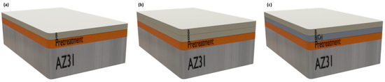
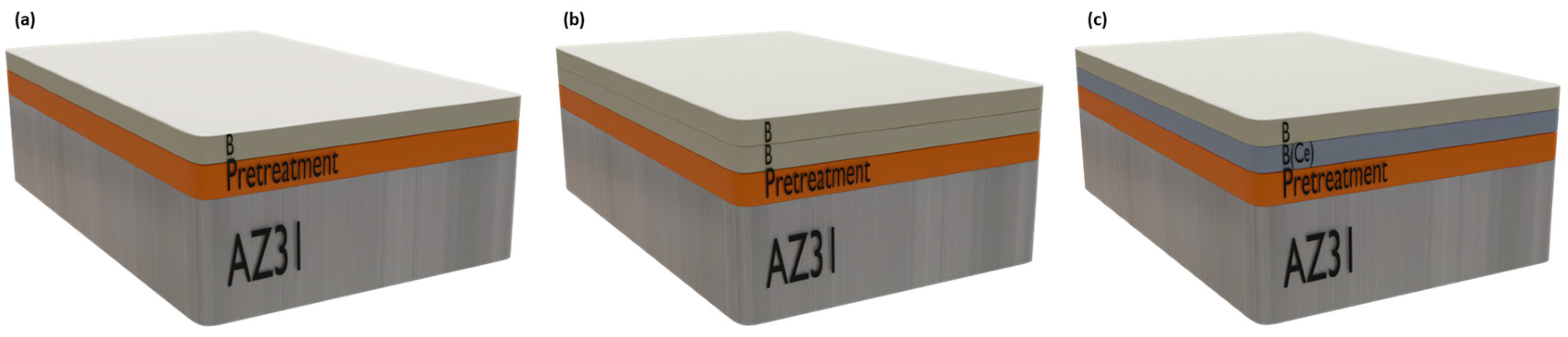
On the other hand, a second waterborne binder with high biobased content (up to 70%) was formulated using 2-octyl acrylate (2-OA) and isobornyl methacrylate (IBOMA) as biobased comonomers, where SIP was also used as surfactant. In addition, CeO2 nanoparticles were incorporated during the miniemulsion polymerization [57] (labelled as B(Ce) layer). Figure 1 shows a schematic illustration of the different systems investigated in this study, including one-layer systems (Figure 1a) and two-layer systems: without nanoparticles (Figure 1b) and with nanoparticles (Figure 1c).
Figure 1.
Schematic representation of the investigated systems: (a) one-layer system, (b) two-layer systems without CeO2 nanoparticles, and (c) two-layer systems with CeO2 nanoparticles.
Both binders were applied using a manual applicator with a height of 100 µm. The coated samples were placed in a climatic chamber at 23 °C for 24 h under 60% relative humidity [45]. The number of systems to be studied (i.e., 8) is summarized in Table 2, indicating the number of organic layers (one or two), the type of waterborne binder (either B or B-B or B(Ce)-B)) and the total thickness.
Table 2.
Properties of the different surface pre-treatments and coated systems.
2.2. Surface Pre-Treatments
Prior to the organic coating, four different pre-treatments were performed:
- Mechanical grinding (labelled as Mech). Samples were ground using consecutive SiC papers from P120 to P1200 grit.
- Pickling (labelled as Chem). A two-step commercial process was used: (i) alkaline cleaning using Bonderite C-AK 4181-L (90 g/L) at 80–90 °C for 10–15 min; (ii) acid etching in Bonderite C-IC 3610 (10 g/L) at room temperature for 2–4 min.
- Pickling followed by a zirconate conversion treatment (ZrCC). The pickling pre-treatment described above was followed by a conversion coating: a mixture of Bonderite M-NT 160 (13 g/L) and Bonderite M-NT 161 (15 g/L) at 35 °C for 1–3 min. Samples were dried for 8 min in warm air.
- Pickling followed by an LDH conversion treatment (labelled as LDH). Pickling pre-treatment followed by a conversion treatment using an aqueous solution with precursors 0.125 M LiNO3, 0.125 M Al(NO3)3·9H2O, and 0.0625 M Na2CO3 in 500 mL (pH ~ 10) with vigorous stirring. The solution was transferred to a PTFE-lined stainless-steel autoclave, and the samples were immersed at 125 °C for 24 h.
After mechanical grinding and pickling, the specimens were rinsed with deionized water, cleaned with isopropyl alcohol, and dried in warm air.
2.3. Characterization
Pre-treatment images were obtained by optical microscopy using a Leica DMi8 M microscope associated with the Leica Application Suite software v3.0.14.2324. Roughness analysis was performed using a focus variation optical profilometer InfiniteFocus S.L. (Alicona, Gmbh, Graz, Austria), employing a 50× magnification lens and analyzing the data obtained with IF-Measure Suite software v5.3. The roughness parameter Sa (arithmetical mean height) was obtained.
Water contact angle measurements were carried out using an FTA1000 Drop Shape Analysis System og First Ten Angstrom (Newark, CA, USA) equipped with a high-speed camera Edmund Optics 5582(Barrington, NJ, USA) and the FTA32 software v2.1. The contact angle was measured over 50 frames taken at 0.5 s intervals, with three measurements performed for each sample. The contact angle and roughness values after each pre-treatment were summarized in Table 2. Although similar surface roughness values were obtained for all chemical treatments (Chem, ZrCC, and LDH), the ZrCC and LDH systems exhibited the highest wettability. This is evidenced by the larger contact angles (and consequently lower wettability) measured for the Mech and Chem pre-treatments.
Coating thicknesses were measured using a Fischer ISOSCOPE-FMP10 portable eddy current metre (Sindelfingen, Germany). Thickness values are reported as the mean and standard deviation of ten measurements per coating.
Adhesion tests were performed using the cross-cut methodology in accordance with the ISO 2409:2020 standard [70]. Each result was assigned a numerical rating from 0 to 5, where 0 represents the best adhesion performance and 5 the poorest.
Plan-view and cross-sectional imaging of different samples were performed by scanning electron microscopy using a JEOL JSM 6400 instrument (Tokyio, Japan), equipped with a backscattered electron (BSE) detector (Abidong, UK) and an Oxford Link Energy-Dispersive X-ray (EDX) microanalysis spectrometer (Abidong, UK). Cross-sectional samples were embedded in a commercial epoxy resin (XF40 (Eybes, France), using XH40 (Eybes, France) as a catalyst agent, NX-MET (Eybes, France)) and prepared by grinding with consecutive SiC papers from P120 to P1200, followed by a final polishing with 1 µm diamond paste.
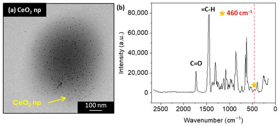
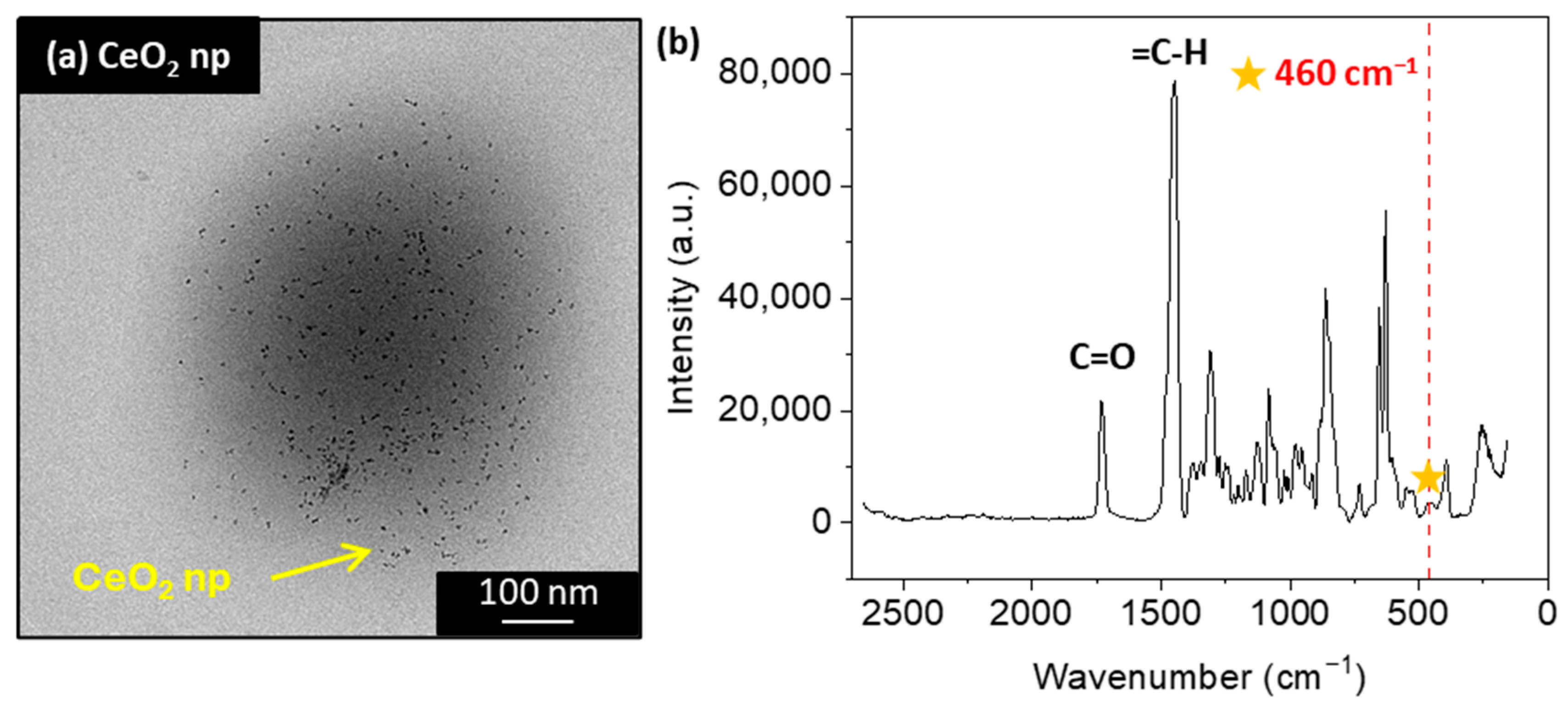
The morphology of the resulting latex particles was examined by Transmission Electron Microscopy (TEM) using a TECNAI G2 20 TWIN (FEI Company, Hillsboro, OR, USA), operating at an accelerating voltage of 200 kV in a bright-field image mode. Figure 2a shows a TEM micrograph of the biobased latex where the CeO2 nanoparticles are visible, discretely distributed, and with no evidence of agglomeration during the polymerization process, with 1 wbm % (weight % with respect to the total weight of monomers) and an average CeO2 nanoparticle size of 6.8 nm. Figure 2b shows the Raman spectrum acquired from the cured biobased film under testing conditions. A distinctive peak is observed around 460 cm−1, corresponding to the symmetrical vibrations of Ce-O bonds [71], which confirms the presence of nanoparticles within the film after its formation.
Figure 2.
(a) TEM micrograph of the hybrid CeO2-acrylic biobased latex polymer particles, and (b) Raman spectrum of the B(Ce) film.
2.4. Corrosion Test
Electrochemical impedance spectroscopy (EIS) measurements (at least in triplicate) were conducted at room temperature using a Gill AC (ACM Instruments, Cumbria, UK) computer-controlled potentiostat. A three-electrode cell was used: the counter electrode was a graphite bar; the reference electrode was a silver/silver chloride (Ag/AgCl, 3 M KCl solution) electrode, and each sample acted as the working electrode. The exposed area of the samples was limited to 1 cm2. A sinusoidal perturbation with an amplitude of 10 mV was applied in the frequency range of 10 kHz to 0.01 Hz. The EIS diagrams were obtained at different immersion times (from 1 h up to 3 days for B systems, and from 1 h up to 35 days for B-B and B(Ce)-B systems) and analyzed using ZView (Scribner Associates Inc., Southern Pines, NC, USA) software v3.1c. The aggressiveness of the electrolyte corresponded to a 0.5 wt.% NaCl aqueous solution for the systems with one coating layer and a 3.5 wt.% NaCl aqueous solution for the systems with two coating layers.
3. Results and Discussion
3.1. Pre-Treatments
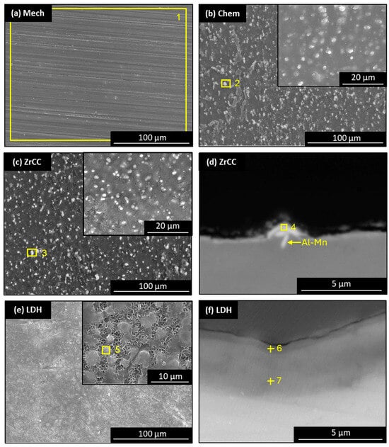
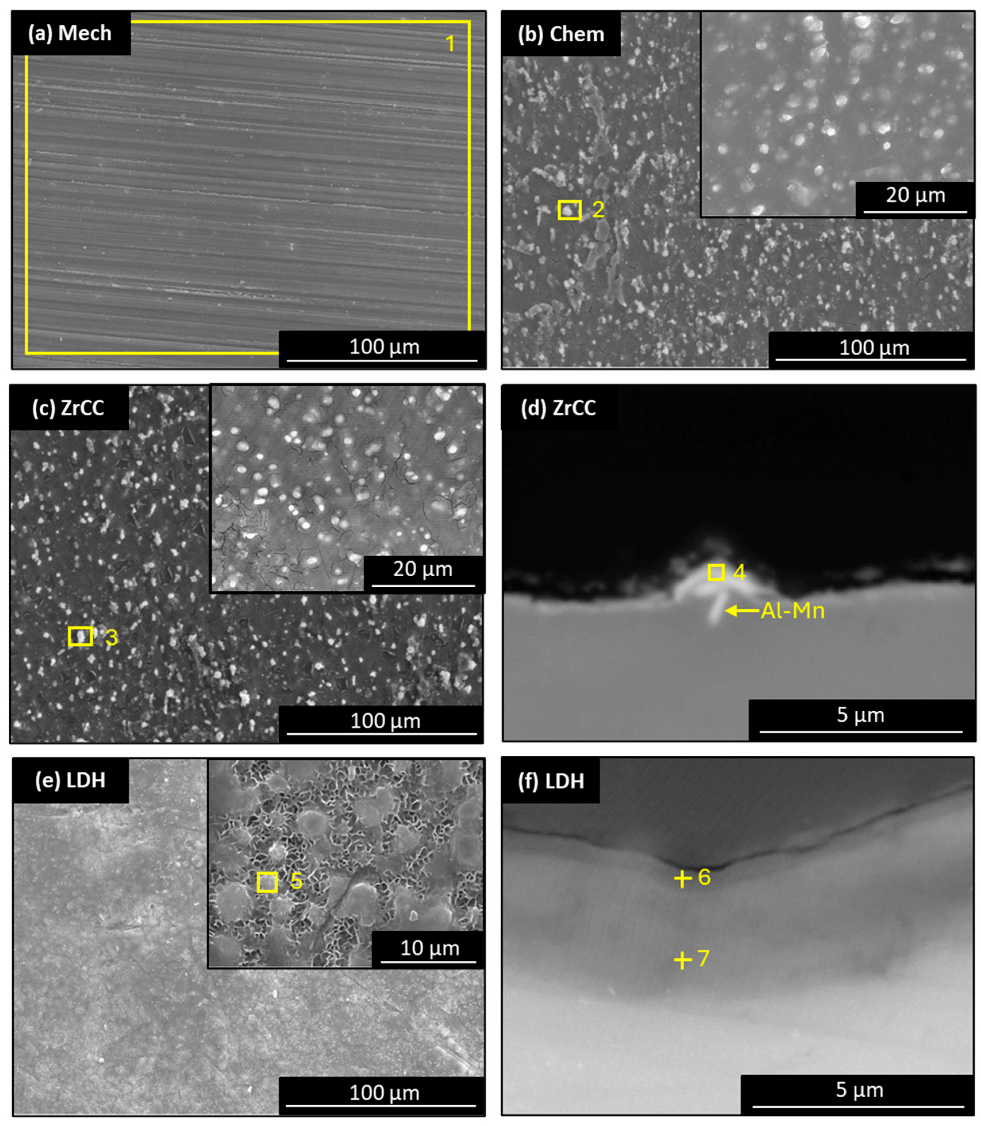
Figure 3 shows micrographs of the AZ31B Mg alloy after different pre-treatments: (a) mechanical (Mech), (b) chemical pickling (Chem), based on degreasing/cleaning and acid etching, (c) conversion coating (CC) based on zirconates (ZrCC), and (d) layered double hydroxide CC (LDH). Plan-view micrographs were obtained using secondary electrons (SE), and cross-sectional micrographs were obtained using backscattered electron (BSE) detectors. The relevant elemental analysis is summarized in Table 3. Mech pre-treatment (Figure 3a) shows the presence of bands oriented along the direction of the mechanical treatment, generated by the action of the abrasive material, as well as the typical composition of the AZ31 alloy. This is because this treatment induces changes only in surface morphology and not in chemical composition. For the Chem (Figure 3b) and ZrCC (Figure 3c) pre-treatments, the presence of S-rich (~1.5 at.%) and Zr-F-rich (between 3 and 5 at.%) particles, respectively, is observed. These particles can be distinguished from the Mg matrix due to their brighter contrast. The incorporation of these elements is associated with the electrolyte composition employed in each pre-treatment, based on sulfuric acid and dihydrogen hexafluorozirconate, respectively. Figure 3d reveals the presence of Al-Mn intermetallic compounds (characteristic of this alloy [72]), as well as the zirconate-based conversion coating covering the surface, with a thickness of approximately 1 µm. In the LDH plan-view micrograph (Figure 3e), the typical flake-like morphology characteristic of this coating is clearly observed. Meanwhile, the cross-sectional micrograph (Figure 3f) reveals a bilayer structure with a total thickness of approximately 4 µm, composed of a dense inner layer mainly formed by Mg(OH)2 (O content ~65 at.%) and an outer layer composed of the previously mentioned flakes, enriched in Al (~17 at.%). This bilayer structure is commonly reported in LDH conversion coatings [73], and is associated with variations in crystallinity and flake size [74,75].
Figure 3.
SEM-SE plan-view for (a) Mech; (b) Chem; (c) ZrCC. (e) LDH and SEM-BSE cross-section for (d) ZrCC; (f) LDH. EDS analysis locations correspond to the data in Table 3.
Table 3.
EDS analysis (at.%) of pre-treatments. Spectrum locations are highlighted in the micrographs shown in Figure 3.
3.2. One-Layer Systems
3.2.1. Characterization
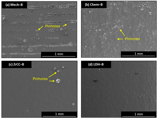
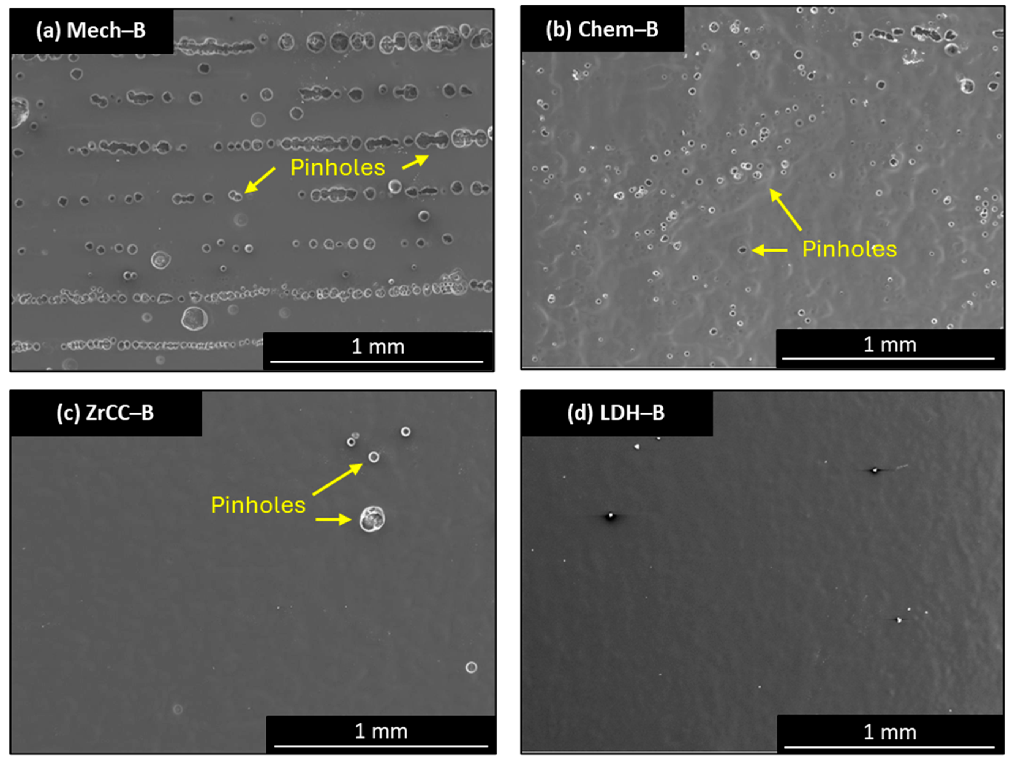
Figure 4 shows SEM-SE plan-view micrographs of each pre-treatment coated with the acrylic binder. Coated Mech-B specimen (Figure 4a) exhibits several large pinholes aligned, which are attributed to mechanical damage produced by the drawdown bar on the metallic surface during the application process. In the case of the coated Chem-B one (Figure 4b), the pinholes are smaller and homogeneously distributed over the surface (without any preferential direction) than those observed in the Mech-B specimen. When coated ZrCC-B (Figure 4c) and coated LDH-B (Figure 4d) systems are explored, a pinhole-free surface is obtained compared to Mech-B and Chem-B systems. Although it implies better homogeneity, certain residual pinholes are still observed in the ZrCC-B specimen. The formation of pinholes might be closely associated with hydrogen evolution (as the predominant cathodic reaction that forms H2) during the corrosion process of Mg [76].
Figure 4.
SEM-SE plan-views micrographs for acrylic binder B applied on (a) Mech; (b) Chem; (c) ZrCC; and (d) LDH.
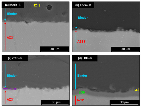
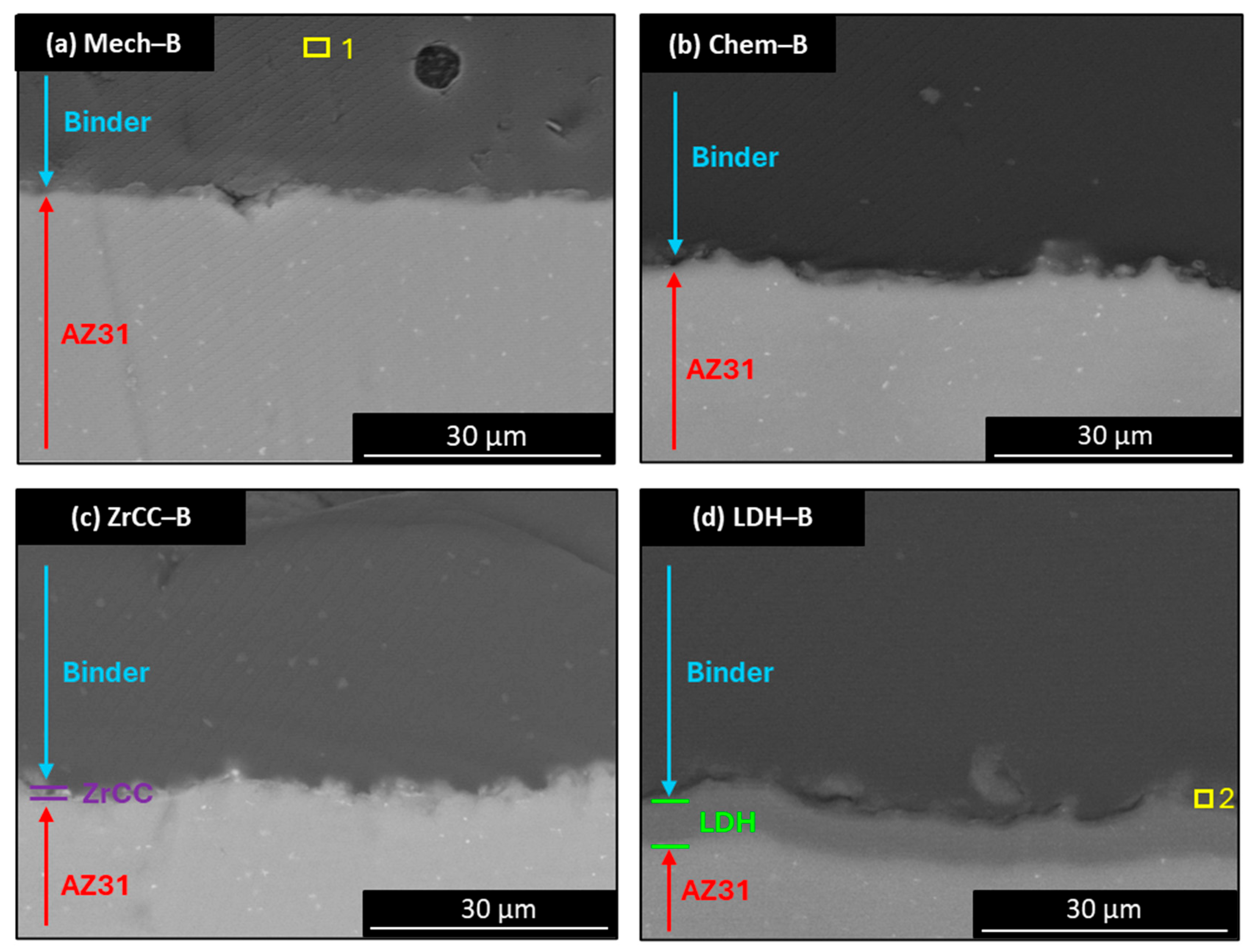
SEM-BSE cross-sectional micrographs of coated (B) systems are presented in Figure 5. A continuous layer over the surface is obtained for all cases, with a coherent pre-treatment/coating interface. The binder employed has a solid content of 50%. Therefore, when the coating is applied using a 100 µm applicator, a theoretical dry film thickness of approximately 50 µm would be expected. However, since water also evaporates during the drying process, the final film thickness is lower than the theoretical value. In addition, the low viscosity of the binder may promote a heterogeneous distribution of the coating. Consequently, thickness values in the range of 20–30 µm (Table 2) were measured for the single-layer systems. Finally, the presence of phosphorous (0.2 at.%) detected by SEM-EDS analysis (Table 4) suggests that phosphatization phenomena at the metal/coating interface have successfully occurred.
Figure 5.
SEM-BSE cross-section micrographs for acrylic binder applied on (a) Mech; (b) Chem; (c) ZrCC; and (d) LDH. EDS analysis locations correspond to the data in Table 4.
Table 4.
EDS analysis (at.%) of coated samples. Spectrum locations are highlighted on the micrographs shown in Figure 5.
Good dry adhesion results are obtained for Mech, Chem, and ZrCC pre-treatments (grade 0), in agreement with results obtained on steel [40]. In contrast, LDH treatment shows lower adhesion capability and may be explained by morphological changes occurring in the outer layer of the LDH coating following the application of the waterborne coating. The presence of water may promote the dissolution of the flakes typically found in LDH systems, which could lead to an increase in surface hydrophobicity and, consequently, reduced adhesion [26]. Further studies are needed to explore this behaviour.
3.2.2. Corrosion Evaluation: Monolayer Systems
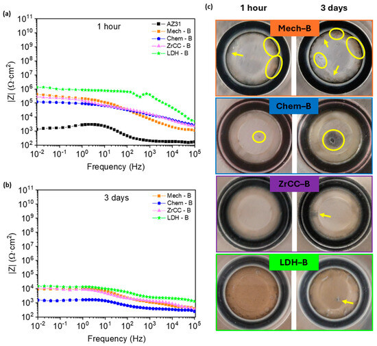
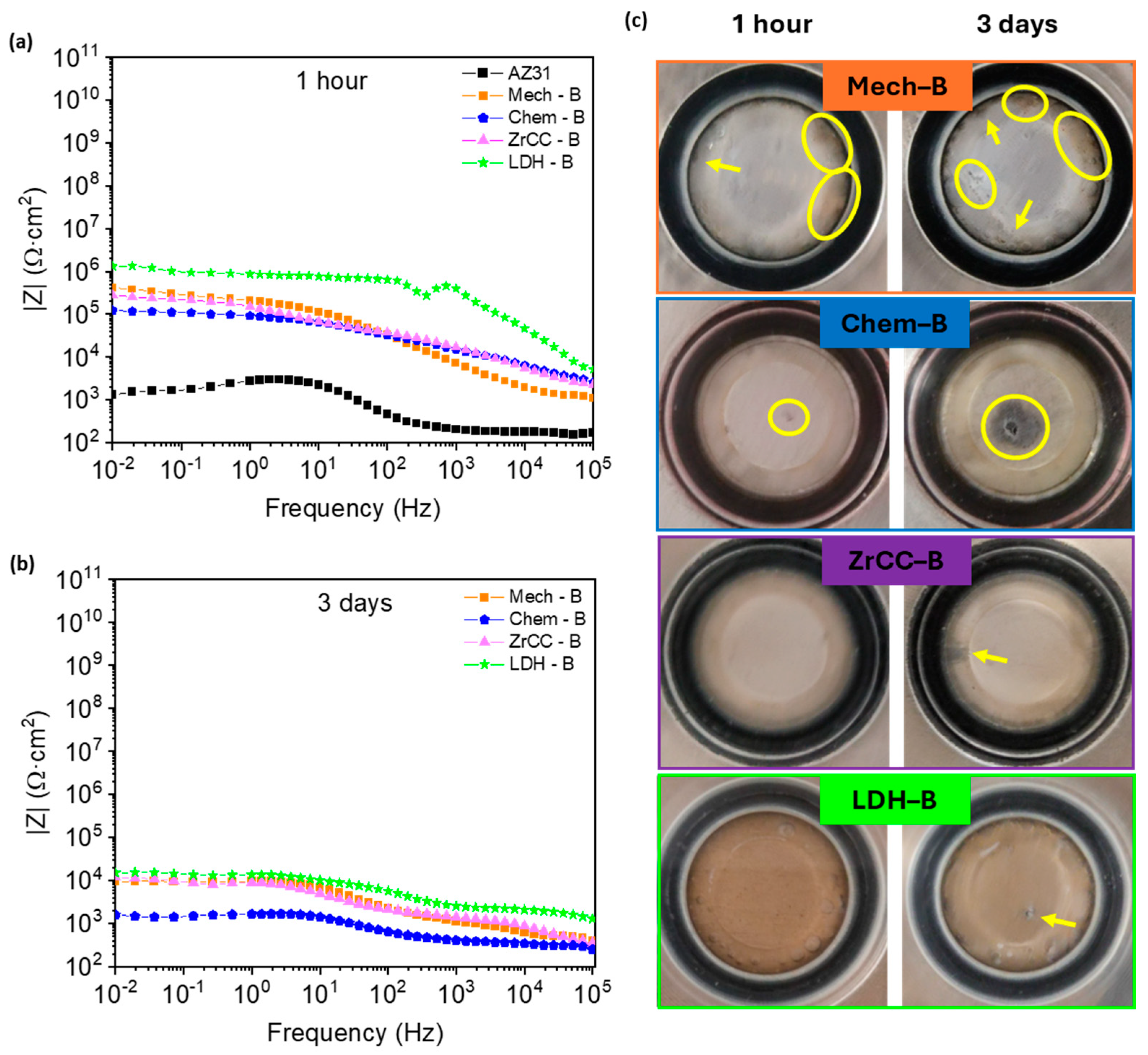
The performance in terms of corrosion resistance is compared by EIS, where the impedance modulus (|Z|) at low frequency (usually 0.01 Hz: |Z|0.01Hz) can be used to compare the different systems: in general, a larger impedance usually means better corrosion resistance. Figure 6 shows the Bode plot (impedance modulus |Z| vs. log frequency) for the different coated pre-treatment-B systems for 1 h and 3 days of immersion in 0.5 wt.% NaCl solution. Uncoated AZ31 magnesium alloy is included as a reference, showing the lowest |Z|0.01Hz after 1 h of immersion in NaCl solution (Figure 6a): 1.3 × 10³ Ω·cm2 for bare AZ31 <<< Chem-B (1.2 × 10⁵ Ω·cm2) < ZrCC-B (2.8 × 10⁵ Ω·cm2) < Mech-B (4.1 × 10⁵ Ω·cm2) << LDH-B (1.3 × 10⁶ Ω·cm2). Results reveal similar values for all the coated systems except LDH-B, which provides the largest impedance value. However, a noticeable decrease in |Z|0.01Hz is observed for all systems after 3 days of immersion (Figure 6b), indicating the lack of protection by the B coating over time. This effect is particularly evident for the Chem-B system, where the |Z|0.01Hz becomes like the bare AZ31 alloy, whilst the remaining coated systems (three out of four) behave in a similar way. Therefore, to discriminate their performance in terms of corrosion protection, Figure 6c shows the visual aspect after 1 h and 3 days. Defects are already observed for Mech-B (see circles and arrows) and Chem-B systems (a small localized one) after 1 h of immersion, and they increase in number (Mech-B) or size (Chem-B) after 3 days. In contrast, the ZrCC-B and LDH-B systems do not exhibit visible defects after 1 h of immersion, but they start to show some of them after 3 days of exposure.
Figure 6.
Corrosion results of the different systems after immersion in 0.5% wt. NaCl: (a) EIS Bode plot after 1 h, (b) EIS Bode plot after 3 days, and (c) macroscopic images after 1 h and 3 days.
As a conclusion, the mechanical and chemical pre-treatments are discarded. Chem-B sample shows the poorest corrosion resistance (lowest |Z|0.01Hz in Figure 6b) and Mech-B sample reveals a high density of surface defects after 3 days of immersion (Figure 6c), although the impedance modulus is similar to the short-listed systems.
Although the LDH-B system seems to exhibit the best performance among the single-layer systems, the impedance modulus remains relatively low for long-term protection using organic coatings. Therefore, a two-layer coating system is explored (below) to improve corrosion resistance by (a) active protection using hybrid CeO2-acrylic biobased latex with CeO2 nanoparticles as corrosion inhibitors in the polymeric matrix [57], and (b) barrier protection by increasing the overall thickness with a second coating layer on top.
3.3. Two-Layer Systems
In this section, two waterborne coatings are studied: (i) the waterborne binder already explored in Section 3.2, without a corrosion inhibitor (labelled as B) (Figure 1b), and (ii) a coating containing CeO2 nanoparticles to be directly applied onto the metal surface (labelled as B(Ce)) (Figure 1c). The B-layer is used either as an inner coating (in contact with the metal) or as the topmost layer to increase the overall coating thickness and to seal pinholes and defects in the coating. Then, considering that only ZrCC and LDH pre-treatments have been employed in this section, the following combinations are investigated (systems from 5 to 8 in Table 2): (n°5) ZrCC-B-B, (n°6) LDH-B-B, (n°7) ZrCC-B(Ce)-B, and (n°8) LDH-B(Ce)-B. Furthermore, the aggressiveness of the electrolyte was also increased to 3.5 wt.% NaCl.
3.3.1. Characterization
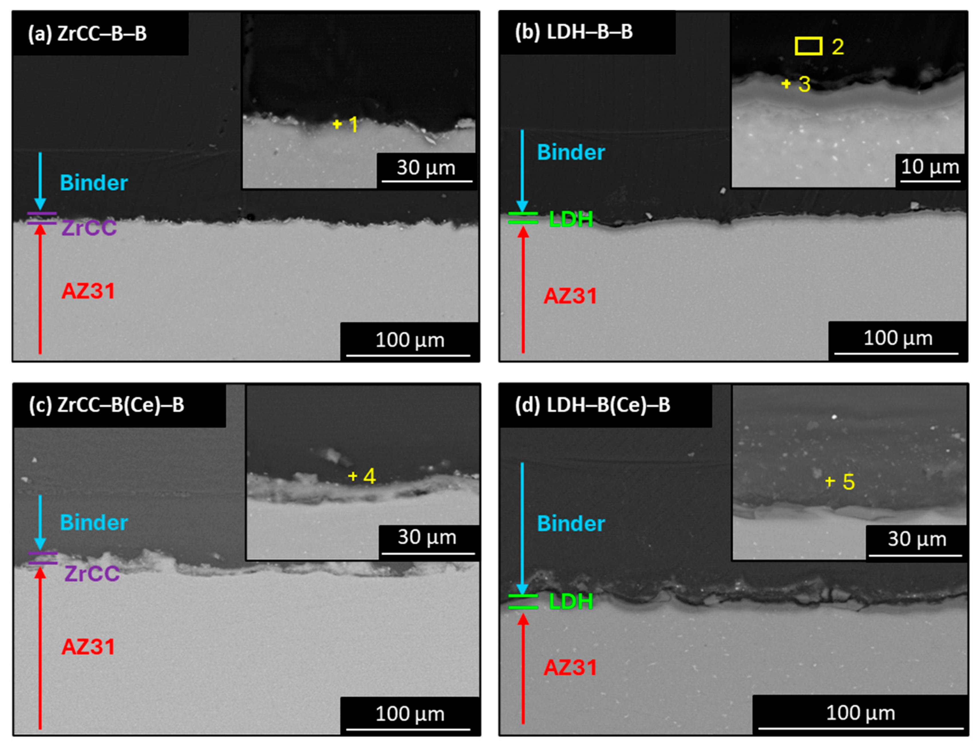
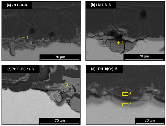
Cross-sectional micrographs for two-layer systems are shown in Figure 7, including detailed views of the coating/pre-treatment interface (upper-right corner of each image). The total thickness (Table 2) is between 54.9 and 56.3 µm for coated ZrCC-based systems and between 66.3 and 73.1 µm for coated LDH-based ones, where the incorporation of a Ce-rich inner layer does not seem to significantly modify the overall thickness.
Figure 7.
Cross-section SEM-BSE images for the two-layer systems: (a) ZrCC-B-B, (b) LDH-B-B, (c) ZrCC-B(Ce)-B, and (d) LDH-B(Ce)-B. EDS analysis locations correspond to the data in Table 5.
The high-magnification insets in Figure 7 show the composition of different spots of interest, where the EDS analysis is performed (Table 5). Spots 1 and 3 indicate the composition of the pre-treatment/organic coating interface for both systems without CeO2 nanoparticles, where the main difference is not only the presence of Zr in spot 1 (Zr-B-B) but also the large amount of Mg due to the low thickness of this ZrCC compared to the larger thickness of LDH CC. On the other hand, spots 2, 4, and 5 are performed in the bulk of the binder, where the presence of Ce is only detected in the inner layer of Zr-B(Ce)-B and LDH-B(Ce)-B systems, in agreement with the findings of Figure 2b. Finally, the presence of phosphorus (0.1 at.%) is detected in almost all systems, but it is missing in the bulk near the interface of LDH-B-B (spot 2) and ZrCC-B(Ce)-B (spot 4).
Table 5.
EDS analysis (at.%) for two-layer systems. Spectrum locations are highlighted on the micrographs shown in Figure 7.
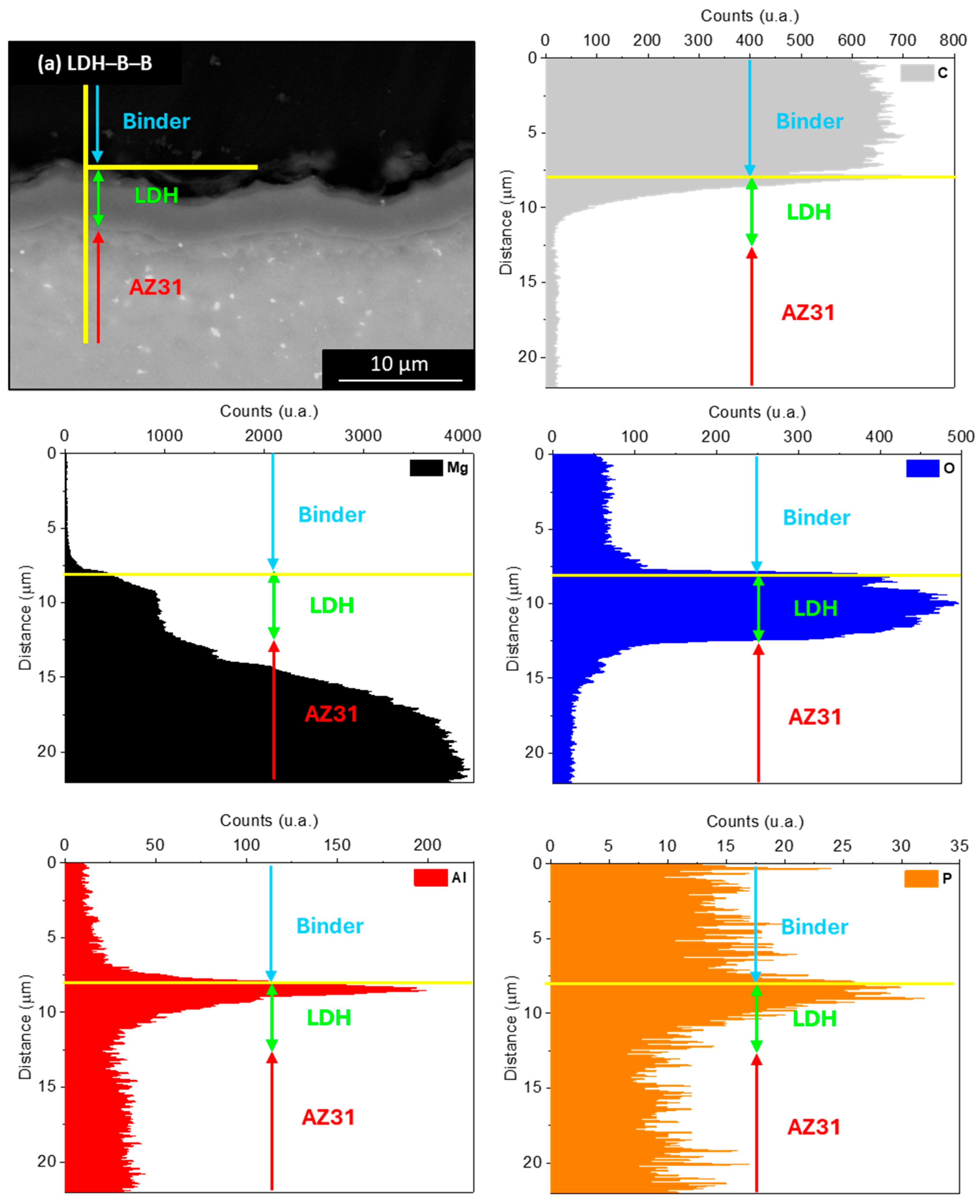
In order to provide more insights about the location of phosphate groups, a detailed cross-sectional analysis (Figure 8) of the LDH-based systems reveals the presence of phosphorus at the boundary of the coating (particularly at the pre-treatment/coating interface), which is in agreement with previous studies where Sipomer is used as a surfmer on bare low carbon steel [77]. Although further studies are required, this suggests the existence of chemical interactions between the LDH surface and the phosphate groups provided by the SIP surfmer [78]. In addition, elemental mapping also reveals the bilayer structure of the LDH systems, with aluminum enrichment in the outermost layer [79] and higher oxygen content in the inner layer, associated with the formation of Mg(OH)2. Carbon maps delimit the acrylic layer, while magnesium is restricted to the inner LDH layer and the substrate.
Figure 8.
SEM-BSE cross-section (a) and EDS maps at the interfaces (binder/LDH and LDH/metal) for the LDH-B-B system.
3.3.2. Corrosion Evaluation: Bilayer Systems
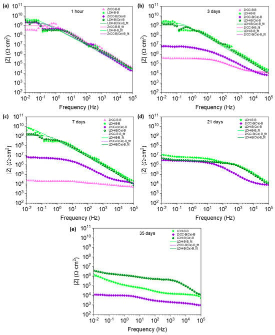
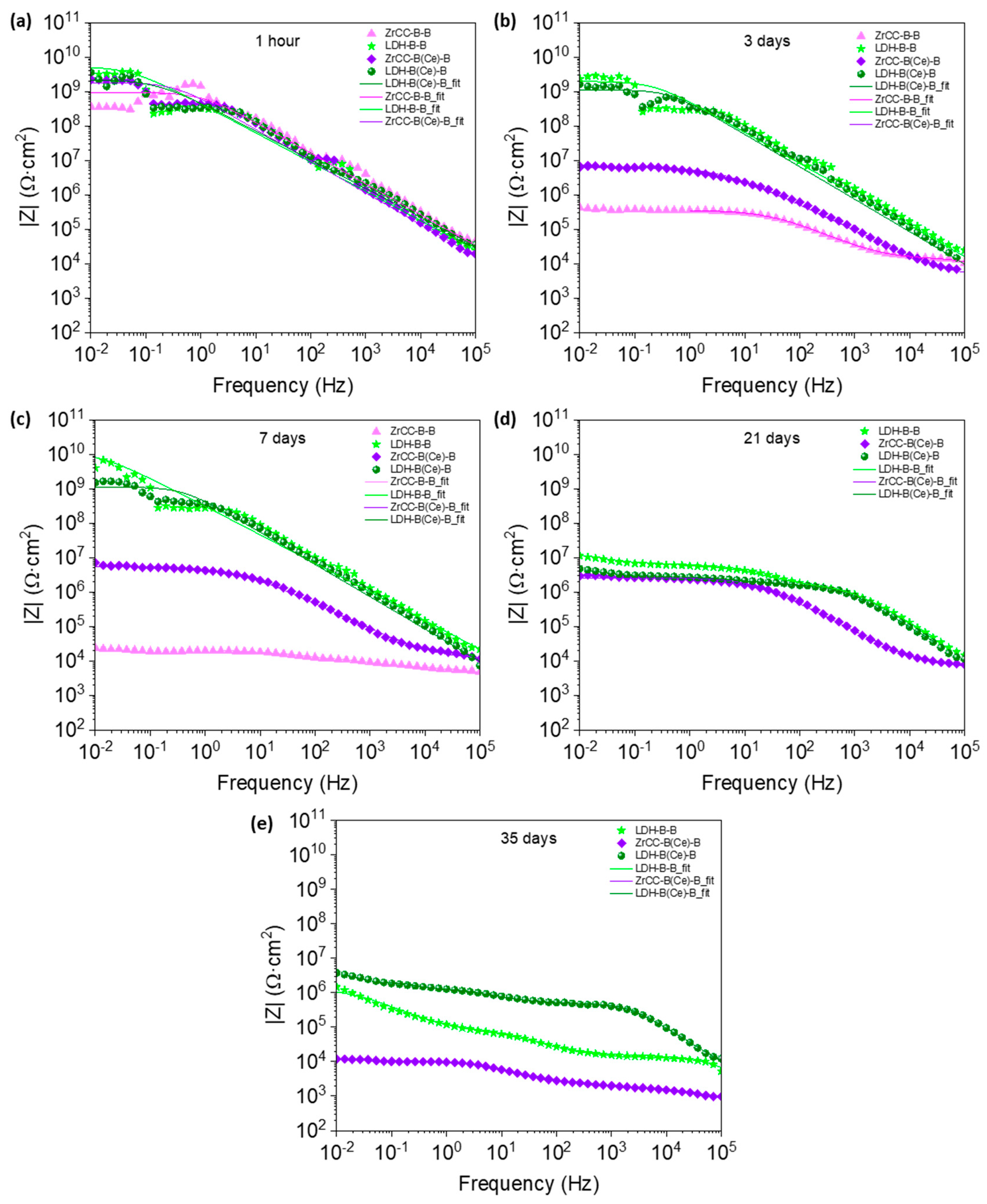
To evaluate the corrosion resistance of the two-layer systems, Bode plots were obtained after immersion in 3.5 wt.% NaCl over time (from 1 h up to 35 days) is presented in Figure 9. Although the EIS diagrams show some instability at low frequencies (particularly below 10−1 Hz for all systems), this does not affect the discussion or conclusions of the manuscript. The differences between systems become evident once the barrier protection of the organic coating has deteriorated and two-time constants appear. The scattered data are observed only in high-impedance systems (|Z|0.01Hz ≈ 108–109 Ω·cm2). In this case, the measurement may approach the limit of the instrument’s current resolution at low frequencies, producing so-called “quantization noise”, which manifests as a staircase-like shape in the spectra [80,81].
Figure 9.
Bode plots for two-layer systems at (a) 1 h, (b) 3 days, (c) 7 days, (d) 21 days, and (e) 35 days in 3.5 wt.% NaCl solution.
Results show good barrier protection (independent of the system) after 1 h of immersion (Figure 9a). However, a drastic change in the EIS diagrams is observed for both systems having ZrCC pre-treatment after 3 days of immersion (Figure 9b). This behaviour is mainly due to the degradation of the metal/coating interface when ZrCC is used, although the presence of CeO2 nanoparticles minimized such degradation compared to the ZrCC-B-B system. The larger impedance modulus |Z|0.01Hz for ZrCC-B(Ce)-B suggests an inhibition effect provided by the CeO2-nanoparticles (|Z|0.01Hz ~ 107 Ω·cm2 instead of |Z|0.01Hz < 106 Ω·cm2). This behaviour is also confirmed after 7 days of immersion (Figure 9c), where the |Z|0.01Hz for ZrCC-B-B is still decreasing (around 104 Ω·cm2) whilst the |Z|0.01Hz for ZrCC-B(Ce)-B remains at a steady state (|Z|0.01Hz around 107 Ω·cm2). In contrast, the two systems with LDH pre-treatment are still providing good barrier protection for up to 7 days of immersion. Interestingly, all systems provide similar impedance diagrams after 21 days of immersion (Figure 9d), except ZrCC-B-B, which has already failed. At longer immersion times (i.e., 35 days), the two LDH-based systems perform better than ZrCC-B(Ce)-B one (|Z|0.01Hz ~ 104 Ω·cm2), indicating the failure of the latter system due to corrosion.
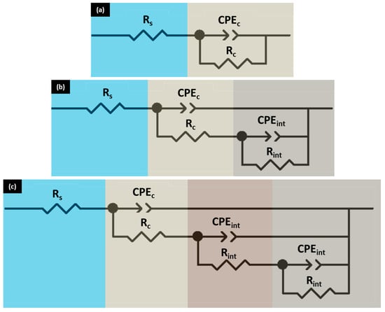
Therefore, in order to provide further insight into the differences in corrosion resistance of the coatings at 21 days of immersion or beyond, several equivalent circuits were used for fitting the EIS data, depending on the number of time constants observed in the diagrams (i.e., Figure 10 shows circuits with one, two, or three of them), where Rs represents the resistance of the electrolyte in all cases. Due to the presence of non-ideal capacitive behaviour in the impedance diagrams, the capacitance may be substituted by a constant phase element (CPE) to define the impedance: , where Y0 is the frequency-independent constant, , is the angular frequency (rad/s), f is the frequency (Hz), and α (0 < α < 1) is a dimensionless parameter related to the width of the distribution of relaxation time. Furthermore, the apparent capacitance can be calculated using the following equation: [82], where Rn is the resistance associated with each time constant (e.g., coating resistance, charge transfer resistance, etc.). For the sake of simplicity, Table 6 only shows the fitting parameters related to two time constants (the one of the waterborne coatings at high frequency and the one of the coating/pre-treatment interface). Furthermore, although αint is reaching values around 0.5 (usually related to the diffusion process) for the system LDH-B(Ce)-B, its roughness at the interface (Figure 3e) cannot be ignored, as it triggers the deviation from an ideal capacitor. Therefore, further studies are needed to clarify it.
Figure 10.
Equivalent circuit with different numbers of time constants: (a) one, (b) two, and (c) three.
Table 6.
Fitting parameters from the EIS diagrams obtained from the different equivalent circuits.
A single time constant is observed for up to 7 days of immersion for three out of the four systems, indicating good barrier protection of the organic coatings, as reflected by the coating capacitance and resistance values (Cc and Rc, respectively) for the LDH-based systems (Table 6), with Cc values being similar for all systems at any immersion time. In contrast, the ZrCC-B-B system already exhibits three time constants due to the failure of the organic coating, where a second time constant is related to the coating/pre-treatment interface (Cint and Rint) and the third one is associated with the corrosion process, represented by the charge transfer resistance and the double layer capacitance (Rct and Cdl, respectively). These results at 7 days reveal the following: (i) although the coated systems with the ZrCC pre-treatment exhibit similar thickness (54.9–56.3 µm), the different behaviour observed between ZrCC-B-B system (poor corrosion resistance) and ZrCC-B(Ce)-B (larger protection) confirms the role of CeO2 nanoparticles as corrosion inhibitors, as previously reported [57], and (ii) a synergy exists between LDH pre-treatment and the organic coating (either B or B(Ce)), which is further supported by the high Rc values obtained for both LDH-based coated systems (~109 Ω·cm2) compared to both ZrCC ones (≤5.4 106 Ω·cm2).
The statement above is also supported by the EIS results after 21 days of immersion. Independent of the Rc value, the two systems with LDH pre-treatment exhibit two time constants. This feature indicates that the organic coating has already failed in the LDH-B-B system (Rc = 1.3 × 10⁶ Ω·cm2) or is about to fail in the LDH-B(Ce)-B system (1.4 × 10⁹ Ω·cm2). However, the apparent capacitance of the coating/pre-treatment interface remains quite low (Cint~10−8–10−9 F/cm2) and its Rint~106 Ω·cm2, indicating the absence of corrosion damage at the interface. The main difference between both systems can be observed after 35 days of immersion, where the system LDH-B-B is showing a larger Cint value (1.8 × 10⁻⁷ F/cm2) and a lower Rint value (8.1 × 10⁴ Ω·cm2) compared to the LDH-B(Ce)-B system (Cint = 5.4 × 10⁻⁸ F/cm2 and 1.1 × 10⁶ Ω·cm2). Once again, when using LDH as a pre-treatment, it is confirmed that the system containing CeO2 nanoparticles (LDH-B(Ce)-B) provides better corrosion protection. Finally, both LDH-based systems show better corrosion resistance than the ZrCC-B(Ce)-B system, which provides the lowest Rint (9.7 × 10³ Ω·cm2) and the largest Cint (3.0 × 10⁻⁶ F/cm2), which could be assigned to a double-layer capacitance (Cdl) rather than to a passive interface.
Therefore, the best combination in terms of corrosion protection is achieved by combining CeO2 nanoparticles with the LDH pre-treatment, and the systems can be classified as follows: LDH-B(Ce)-B > LDH-B-B > ZrCC-B(Ce)-B > ZrCC-B-B.
3.4. Characterization After Corrosion
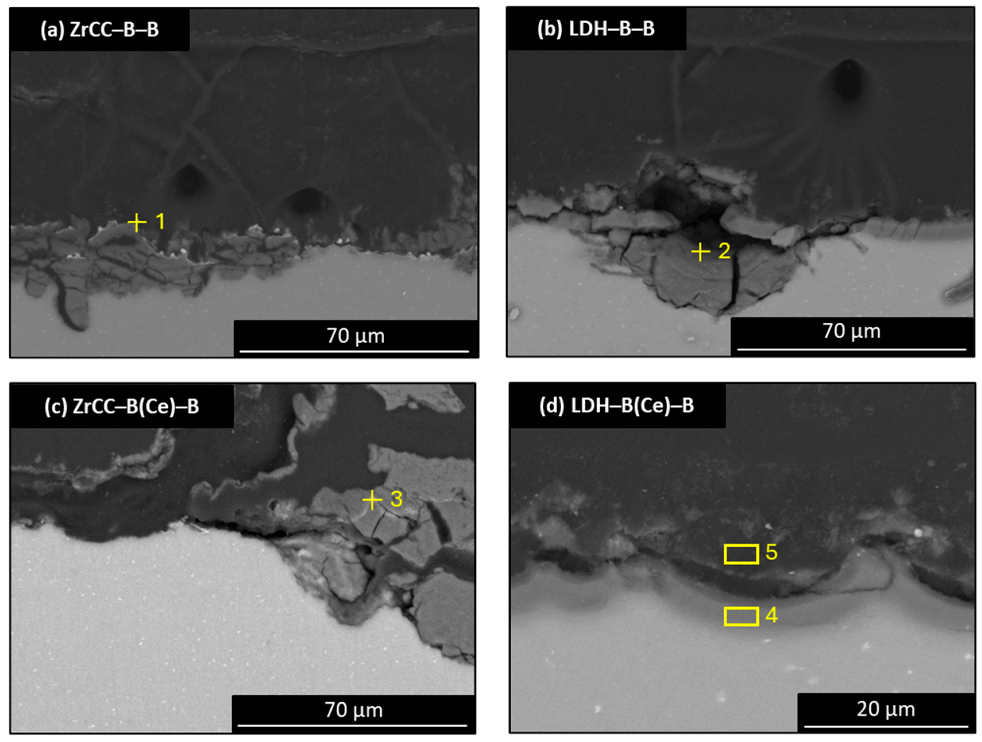
The microstructural characterization of the coatings after exposure to the aggressive solution was carried out using the SEM-EDS technique. This approach enables a detailed evaluation of morphology, interfacial integrity, and chemical composition of coated specimens (either B-B or B(Ce)-B systems) pre-treated with ZrCC and LDH CC (Figure 11). The correlation between the electrochemical response and the surface characterization provided by SEM-EDX analysis allows a deeper understanding of the corrosion protection mechanisms in the different systems.
Figure 11.
SEM cross-section after 35 days of exposure to 3.5% wt. NaCl solution for the systems: (a) ZrCC-B-B; (b) LDH-B-B; (c) ZrCC-B(Ce)-B; and (d) LDH-B(Ce)-B. EDS analysis locations correspond to the data in Table 7.
Cross-sectional micrographs of the ZrCC-B-B (Figure 11a) and LDH-B-B (Figure 11b) systems reveal the presence of corrosion products, together with clear evidence of degradation or partial dissolution of the pre-treatment layers, whereas the systems with CeO2 nanoparticles show an opposite behaviour. On the one hand, ZrCC-B(Ce)-B system (Figure 11c) shows degradation levels comparable to those observed for the Ce-free systems. However, a significantly enhanced protective effect is observed in the LDH-B(Ce)-B specimen (Figure 11d), in which the LDH layer remains intact, and no detectable signs of corrosion are observed.
SEM-EDS results (Table 7) further support the trends observed in the microstructural analysis. For the B-B-coated systems, a high phosphorus content (0.6 at.%) is detected, which is associated with the formation of phosphate-containing corrosion products. In addition, the high chloride content (1 at.%) indicates the penetration of chloride anions through the coating, reaching the pre-treatment/coating interface.
In contrast, the systems with B(Ce) inner layer exhibit a marked reduction in chloride content (0.2 at.% for ZrCC and 0.1 at.% for LDH), suggesting the inhibitor effect provided by the incorporation of CeO2 nanoparticles in the inner layer. These nanoparticles hinder the transport of aggressive species and delay the onset of interfacial degradation, thereby enhancing the overall corrosion resistance of two-layer systems.
Table 7.
EDS analysis (at.%) of a multilayered system. Spectrum locations are highlighted on the micrographs shown in Figure 11.
3.5. Corrosion Inhibition Mechanism
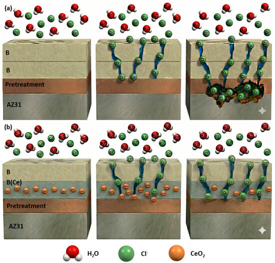
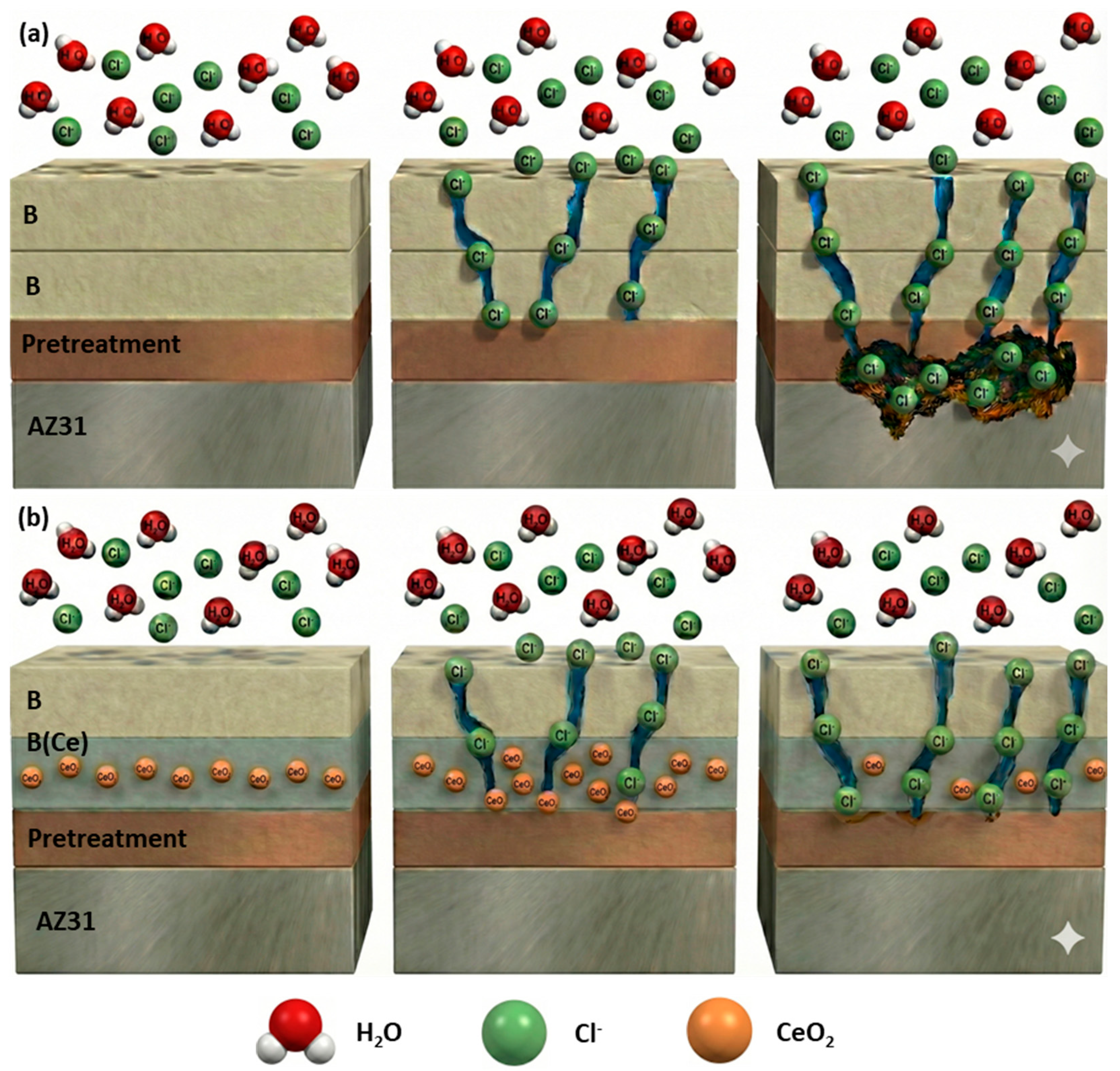
Figure 12 shows a schematic representation of the proposed mechanism. If the organic coating has not failed yet, a single time constant is expected, providing mainly information on the barrier protection of the organic coatings (left images in Figure 12a,b). However, once the organic coating has failed, a second time constant becomes visible at medium–low frequencies (central images in Figure 12a,b) related to the coating/pre-treatment interface (Cint and Rint). Depending on the type of pre-treatment, the rapid access of water compromises the protection, triggering the corrosion process and showing the presence of a third time constant (Rct and Cdl) associated with the corrosion process itself (especially in both ZrCC systems, as shown in the right images in Figure 12a,b). The enhanced corrosion resistance provided by the LDH-B-B system is mainly attributed to two main factors:
Figure 12.
Schematic corrosion mechanism proposed for (a) B or B-B systems; and (b) B(Ce)-B systems (figure generated using Google Gemini AI tool, Gemini 3 Flash version).
- The presence of a second layer (B coating) enhances the barrier capabilities against aggressive anions, hindering access to the AZ31 substrate;
- The anion-exchange capability of the LDH pre-treatment, which enables active corrosion protection and reduces the overall corrosion rate of the magnesium alloy [83].
Additionally, the incorporation of a layer containing CeO2 nanoparticles produces better corrosion performance compared to Ce-free systems, particularly when it is combined with LDH pre-treatment. In this case, corrosion performance is improved due to the synergy between the anion-exchange of the LDH (able to trap chloride ions) and the corrosion inhibition provided by CeO2 nanoparticles. These nanoparticles not only act as a physical barrier blocking the electrolyte diffusion pathways, but also serve as active corrosion inhibitors that are able to stabilize magnesium corrosion products (blocking the access of the electrolyte) and to decrease the cathodic activity [84,85].
4. Conclusions
- The presence of phosphorus at the coating/pre-treatment interface was confirmed by SEM-EDS, suggesting phosphatization triggered by the SIP surfmer.
- The corrosion performance of single-layer coated systems is strongly affected by the surface pre-treatment: both conversion coatings (LDH and ZrCC) provided higher corrosion resistance compared to the Mech and Chem ones. However, long-term corrosion protection was poor, and a second organic layer was needed.
- Two-layer systems provided higher corrosion resistance compared to single-layer ones, increasing |Z0.01Hz| values by several orders of magnitude. Further improvement was observed with the incorporation of CeO2 nanoparticles into a biobased waterborne binder. LDH-B(Ce)-B system yielded the highest corrosion resistance, reaching 3.7 × 10⁶ Ω·cm2 after 35 days of immersion in 3.5 wt.% NaCl solution and showing lower degradation compared to ZrCC-B(Ce)-B or LDH-B-B systems.
- Post-mortem analysis by SEM-EDS of corroded (two-layer) samples has revealed phosphate-rich corrosion products and significant chloride content either in B-B systems or ZrCC-B(Ce)-B one. In contrast, the LDH-B(Ce)-B system exhibited minimal chloride uptake, and the integrity of the LDH CC was preserved, suggesting a synergistic inhibition effect provided by the CeO2 nanoparticles.
- The role of CeO2 nanoparticles as corrosion inhibitors was confirmed, particularly when ZrCC pre-treatment was used: the ZrCC-B-B system showed poor corrosion resistance compared to the ZrCC-B(Ce)-B one after 7 days of immersion in NaCl solution.
Author Contributions
Conceptualization, J.G.-G., M.M., R.A., and J.M.V.; methodology, J.G.-G., M.M., R.A., and J.M.V.; validation, J.G.-G., and J.M.V.; formal analysis, J.G.-G., M.M., R.A., and J.M.V.; investigation, J.G.-G., M.P., J.R.L., and J.M.V.; resources, M.P., J.R.L., and J.M.V.; data curation, J.G.-G. and J.M.V.; writing—original draft preparation, J.G.-G.; writing—review and editing, J.G.-G., M.M., M.P., J.R.L., and J.M.V.; visualization, J.G.-G.; supervision, M.M., R.A., and J.M.V.; project administration, M.M., R.A., and J.M.V.; funding acquisition, R.A. and J.M.V. All authors have read and agreed to the published version of the manuscript.
Funding
The authors gratefully acknowledge the support from project PID2024-158719OB-C33, funded by MICIU/AEI/10.13039/501100011033/FEDER, UE, and CPP2022-009764, funded by MICIU/AEI/10.13039/501100011033/FEDER, UE. J.M.V. also acknowledges grant RYC2021-034384-I, funded by MICIU/AEI/10.13039/501100011033 and the European Union NextGenerationEU/PRTR.
Data Availability Statement
All data presented in this work will be made available through the Docta Complutense repository: https://docta.ucm.es/handle/20.500.14352/16 (accessed on 14 February 2026).
Acknowledgments
During the preparation of this manuscript/study, the authors used Google Gemini (OpenAI, Gemini 3 Flash version) to generate Figure 12, and the resulting image was manually reviewed and edited to ensure scientific accuracy and relevance.
Conflicts of Interest
The authors declare that they have no known competing financial interests or personal relationships that could have appeared to influence the work reported in this paper.
Abbreviations
The following abbreviations are used in this manuscript:
| LDH | Layered Double Hydroxides |
| SEM | Scanning Electron Microscopy |
| EDS | Energy Dispersive X-Ray Spectroscopy |
| EIS | Electrochemical Impedance Spectroscopy |
| CC | Conversion Coating |
| PEO | Plasma Electrolytic Oxidation |
| CCC | Chromate Conversion Coatings |
| VOCs | Volatile Organic Compounds |
| SIP | Sipomer® PAM-200 |
| 2-OA | 2-Octyl Acrylate |
| IBOMA | Isobornyl Methacrylate |
| MMA | Methyl Methacrylate |
| BA | Butyl Acrylate |
| Mech | Mechanical Grinding |
| Chem | Pickling |
| ZrCC | Pickling Followed by a Conversion Treatment |
| BSE | Backscattered Electrons |
| EDX | Energy Dispersive X-Ray |
| TEM | Transmission Electron Microscopy |
| SE | Secondary Electrons |
References
- Tan, J.; Ramakrishna, S. Applications of Magnesium and Its Alloys: A Review. Appl. Sci. 2021, 11, 6861. [Google Scholar] [CrossRef] [Scilit]
- Chalisgaonkar, R. Insight in Applications, Manufacturing and Corrosion Behaviour of Magnesium and Its Alloys—A Review. Mater. Today Proc. 2020, 26, 1060–1071. [Google Scholar] [CrossRef] [Scilit]
- Kulekci, M.K. Magnesium and Its Alloys Applications in Automotive Industry. Int. J. Adv. Manuf. Technol. 2008, 39, 851–865. [Google Scholar] [CrossRef] [Scilit]
- Li, N.; Wang, C.; Monclús, M.A.; Yang, L.; Molina-Aldareguia, J.M. Solid Solution and Precipitation Strengthening Effects in Basal Slip, Extension Twinning and Pyramidal Slip in Mg-Zn Alloys. Acta Mater. 2021, 221, 117374. [Google Scholar] [CrossRef] [Scilit]
- Esmaily, M.; Svensson, J.E.; Fajardo, S.; Birbilis, N.; Frankel, G.S.; Virtanen, S.; Arrabal, R.; Thomas, S.; Johansson, L.G. Fundamentals and Advances in Magnesium Alloy Corrosion. Prog. Mater. Sci. 2017, 89, 92–193. [Google Scholar] [CrossRef] [Scilit]
- Song, G.; Atrens, A. Understanding Magnesium Corrosion. A Framework for Improved Alloy Performance. Adv. Eng. Mater. 2003, 5, 837–858. [Google Scholar] [CrossRef] [Scilit]
- Atrens, A.; Song, G.L.; Liu, M.; Shi, Z.; Cao, F.; Dargusch, M.S. Review of Recent Developments in the Field of Magnesium Corrosion. Adv. Eng. Mater. 2015, 17, 400–453. [Google Scholar] [CrossRef] [Scilit]
- Song, J.; She, J.; Chen, D.; Pan, F. Latest Research Advances on Magnesium and Magnesium Alloys Worldwide. J. Magnes. Alloys 2020, 8, 1–41. [Google Scholar] [CrossRef] [Scilit]
- Vinoth Kumar, C.; Rajyalakshmi, G.; Kartha, J. Insights on Anti-Corrosion Coating of Magnesium Alloy: A Review. J. Bio-Tribo-Corros. 2022, 9, 13. [Google Scholar] [CrossRef] [Scilit]
- International Organization for Standardization. Preparation of Steel Substrates Before Application of Paints and Related Products—Visual Assessment of Surface Cleanliness—Part 1: Rust Grades and Preparation Grades of Uncoated Steel Substrates and of Steel Substrates After Overall Removal of Previous Coatings; International Organization for Standardization: Geneva, Switzerland, 2007. [Google Scholar]
- Li, Q.; Liang, P.; Li, Y.; Ye, Z.; Zhang, B.; Ji, C. The Use of Phytic Acid Conversion Coating to Enhance the Corrosion Resistance of AZ91D Magnesium Alloy. Int. J. Electrochem. Sci. 2022, 17, 22095. [Google Scholar] [CrossRef] [Scilit]
- Saran, D.; Kumar, A.; Bathula, S.; Klaumünzer, D.; Sahu, K.K. Review on the Phosphate-Based Conversion Coatings of Magnesium and Its Alloys. Int. J. Miner. Metall. Mater. 2022, 29, 1435–1452. [Google Scholar] [CrossRef] [Scilit]
- Chen, Q.; Lu, X.; Serdechnova, M.; Wang, C.; Lamaka, S.; Blawert, C.; Zheludkevich, M.L.; Wang, F. Formation of Self-Healing PEO Coatings on AM50 Mg by In-Situ Incorporation of Zeolite Micro-Container. Corros. Sci. 2022, 209, 110785. [Google Scholar] [CrossRef] [Scilit]
- Wierzbicka, E.; Vaghefinazari, B.; Lamaka, S.V.; Zheludkevich, M.L.; Mohedano, M.; Moreno, L.; Visser, P.; Rodriguez, A.; Velasco, J.; Arrabal, R.; et al. Flash-PEO as an Alternative to Chromate Conversion Coatings for Corrosion Protection of Mg Alloy. Corros. Sci. 2021, 180, 109189. [Google Scholar] [CrossRef] [Scilit]
- Xu, Y.; Guo, Y.; Li, G.; Lian, J. Biodegradable Phytic Acid Conversion Coatings on Magnesium Alloy for Temporary Orthopedic Implant: A Review. Prog. Org. Coat. 2022, 169, 106920. [Google Scholar] [CrossRef] [Scilit]
- Pommiers-Belin, S.; Frayret, J.; Uhart, A.; Ledeuil, J.; Dupin, J.-C.; Castetbon, A.; Potin-Gautier, M. Determination of the Chemical Mechanism of Chromate Conversion Coating on Magnesium Alloys EV31A. Appl. Surf. Sci. 2014, 298, 199–207. [Google Scholar] [CrossRef] [Scilit]
- Liao, S.; Yu, B.; Zhang, X.; Lu, X.; Zhou, P.; Zhang, C.; Chen, X.; Zhang, T.; Wang, F. New Design Principles for the Bath towards Chromate- and Crack-Free Conversion Coatings on Magnesium Alloys. J. Magnes. Alloys 2021, 9, 505–519. [Google Scholar] [CrossRef] [Scilit]
- Pommiers, S.; Frayret, J.; Castetbon, A.; Potin-Gautier, M. Alternative Conversion Coatings to Chromate for the Protection of Magnesium Alloys. Corros. Sci. 2014, 84, 135–146. [Google Scholar] [CrossRef] [Scilit]
- Hafeez, M.A.; Farooq, A.; Zang, A.; Saleem, A.; Deen, K.M. Phosphate Chemical Conversion Coatings for Magnesium Alloys: A Review. J. Coat. Technol. Res. 2020, 17, 827–849. [Google Scholar] [CrossRef] [Scilit]
- Saran, D.; Pathak, A.D.; Klaumünzer, D.; Bathula, S.; Sahu, K.K. Novel Perspectives on the Mechanism of Phosphate Conversion Coating on Magnesium Alloys. Results Surf. Interfaces 2024, 16, 100243. [Google Scholar] [CrossRef] [Scilit]
- Jian, S.-Y.; Chu, Y.-R.; Lin, C.-S. Permanganate Conversion Coating on AZ31 Magnesium Alloys with Enhanced Corrosion Resistance. Corros. Sci. 2015, 93, 301–309. [Google Scholar] [CrossRef] [Scilit]
- Hung, S.-M.; Chen, S.-Y.; Lin, C.-S. Effect of Bath Temperature on the Growth Kinetics and Characteristics of Permanganate Conversion Coating on LZ91 Magnesium Alloy. J. Mater. Res. Technol. 2024, 28, 4567–4576. [Google Scholar] [CrossRef] [Scilit]
- Saji, V.S. Review of Rare-Earth-Based Conversion Coatings for Magnesium and Its Alloys. J. Mater. Res. Technol. 2019, 8, 5012–5035. [Google Scholar] [CrossRef] [Scilit]
- Amini, R.; Kardar, P. Rare Earth-Based Conversion Coatings under Scrutiny: A Comprehensive Review. J. Rare Earths 2025, 43, 859–873. [Google Scholar] [CrossRef] [Scilit]
- Qi, J.; Ye, Z.; Gong, N.; Qu, X.; Mercier, D.; Światowska, J.; Skeldon, P.; Marcus, P. Formation of a Trivalent Chromium Conversion Coating on AZ91D Magnesium Alloy. Corros. Sci. 2021, 186, 109459. [Google Scholar] [CrossRef] [Scilit]
- Pillado, B.; Mingo, B.; del Olmo, R.; Matykina, E.; Kooijman, A.M.; Gonzalez−Garcia, Y.; Arrabal, R.; Mohedano, M. LDH Conversion Films for Active Protection of AZ31 Mg Alloy. J. Magnes. Alloys 2023, 11, 201–216. [Google Scholar] [CrossRef] [Scilit]
- Li, Q.; Zhang, X.; Ben, S.; Zhao, Z.; Ning, Y.; Liu, K.; Jiang, L. Bio-Inspired Superhydrophobic Magnesium Alloy Surfaces with Active Anti-Corrosion and Self-Healing Properties. Nano Res. 2022, 16, 3312–3319. [Google Scholar] [CrossRef] [Scilit]
- Guo, L.; Wu, W.; Zhou, Y.; Zhang, F.; Zeng, R.; Zeng, J. Layered Double Hydroxide Coatings on Magnesium Alloys: A Review. J. Mater. Sci. Technol. 2018, 34, 1455–1466. [Google Scholar] [CrossRef] [Scilit]
- Zhu, Y.-X.; Song, G.-L.; Zheng, D.-J.; Serdechnova, M.; Blawert, C.; Zheludkevich, M.L. In Situ Synergistic Strategy of Sacrificial Intermedium for Scalable-Manufactured and Controllable Layered Double Hydroxide Film. Sci. China Mater. 2022, 65, 1842–1852. [Google Scholar] [CrossRef] [Scilit]
- Iqbal, M.A.; Neves, C.; Starykevich, M.; Martins, R.; Ferreira, M.G.S.; Tedim, J. In Situ Grown Gluconate-Containing CaAl-LDH/Organic Coating for Steel Corrosion Protection. J. Coat. Technol. Res. 2024, 22, 619–630. [Google Scholar] [CrossRef] [Scilit]
- Majidi, R.; Nouri, N.; Keramatinia, M.; Davarpanah, A.; Soroush, E.; Ramezanzadeh, B. ZPCC-Zn-Al-LDH Surface Bilayer; toward Designing a Durable Self-Healable Nano-Structured Film with the Utmost Corrosion Resistance. J. Taiwan Inst. Chem. Eng. 2024, 156, 105343. [Google Scholar] [CrossRef] [Scilit]
- Zhou, H.; Chen, R.; Liu, Q.; Liu, J.; Yu, J.; Wang, C.; Zhang, M.; Liu, P.; Wang, J. Fabrication of ZnO/Epoxy Resin Superhydrophobic Coating on AZ31 Magnesium Alloy. Chem. Eng. J. 2019, 368, 261–272. [Google Scholar] [CrossRef] [Scilit]
- Li, J.; Bai, H.; Feng, Z. Advances in the Modification of Silane-Based Sol-Gel Coating to Improve the Corrosion Resistance of Magnesium Alloys. Molecules 2023, 28, 2563. [Google Scholar] [CrossRef] [Scilit]
- Cheng, G.; Greenland, B.W.; Lampard, C.; Williams, N.; Bahra, M.S.; Hayes, W. Lightly Branched Comb Polyesters: Application in Fast Drying Solvent-Borne Coating Formulations. React. Funct. Polym. 2013, 73, 619–623. [Google Scholar] [CrossRef] [Scilit]
- Wang, D.; Yu, H.; Shao, X.; Yu, H.; Nie, L. Direct and Potential Risk Assessment of Exposure to Volatile Organic Compounds for Primary Receptor Associated with Solvent Consumption. Environ. Pollut. 2018, 233, 501–509. [Google Scholar] [CrossRef] [Scilit]
- Quites, D.; Leiza, J.R.; Mantione, D.; Somers, A.; Forsyth, M.; Paulis, M. Incorporation of a Coumarate Based Corrosion Inhibitor in Waterborne Polymeric Binders for Corrosion Protection Applications. Macromol. Mater. Eng. 2022, 307, 2100772. [Google Scholar] [CrossRef] [Scilit]
- Wang, X.; Li, C.; Zhang, M.; Lin, D.; Yuan, S.; Xu, F.; Zhou, Y.; Wang, C.; Zhu, Y.; Wang, H. A Novel Waterborne Epoxy Coating with Anti-Corrosion Performance under Harsh Oxygen Environment. Chem. Eng. J. 2022, 430, 133156. [Google Scholar] [CrossRef] [Scilit]
- Kumar, R.; Karade, S.S.; Shinde, S.K.; Warkhade, S.K. Enhanced Corrosion Protection of Cu & Al in Saline Media Using a New PEDOT Based Waterborne Polyurethane Coating. Results Surf. Interfaces 2023, 12, 100139. [Google Scholar] [CrossRef] [Scilit]
- Machotová, J.; Kalendová, A.; Voleská, M.; Steinerová, D.; Pejchalová, M.; Knotek, P.; Zárybnická, L. Waterborne Hygienic Coatings Based on Self-Crosslinking Acrylic Latex with Embedded Inorganic Nanoparticles: A Comparison of Nanostructured ZnO and MgO as Antibacterial Additives. Prog. Org. Coat. 2020, 147, 105704. [Google Scholar] [CrossRef] [Scilit]
- González, I.; Mestach, D.; Leiza, J.R.; Asua, J.M. Adhesion Enhancement in Waterborne Acrylic Latex Binders Synthesized with Phosphate Methacrylate Monomers. Prog. Org. Coat. 2008, 61, 38–44. [Google Scholar] [CrossRef] [Scilit]
- Han, K.; Liu, J.; Hao, F.; Wang, J.; Yuan, J.; Pan, Z.; Pan, M. An Adaptive Waterborne Fluorocarbon Coatings with Anti-Flashing Rust, Antibiofouling, and Self-Repairing Properties. Chem. Eng. J. 2024, 495, 153644. [Google Scholar] [CrossRef] [Scilit]
- Butler, L.N.; Fellows, C.M.; Gilbert, R.G. Effect of Surfactant Systems on the Water Sensitivity of Latex Films. J. Appl. Polym. Sci. 2004, 92, 1813–1823. [Google Scholar] [CrossRef] [Scilit]
- Aguirreurreta, Z.; de la Cal, J.C.; Leiza, J.R. Preparation of High Solids Content Waterborne Acrylic Coatings Using Polymerizable Surfactants to Improve Water Sensitivity. Prog. Org. Coat. 2017, 112, 200–209. [Google Scholar] [CrossRef] [Scilit]
- Vega, J.M.; Chimenti, S.; García-Lecina, E.; Grande, H.-J.; Paulis, M.; Leiza, J.R. Impact of the In-Situ Phosphatization on the Corrosion Resistance of Steel Coated with Fluorinated Waterborne Binders Assessed by SKP and EIS. Prog. Org. Coat. 2020, 148, 105706. [Google Scholar] [CrossRef] [Scilit]
- Chimenti, S.; Vega, J.M.; García-Lecina, E.; Grande, H.-J.; Paulis, M.; Leiza, J.R. In-Situ Phosphatization and Enhanced Corrosion Properties of Films Made of Phosphate Functionalized Nanoparticles. React. Funct. Polym. 2019, 143, 104334. [Google Scholar] [CrossRef] [Scilit]
- Chimenti, S.; Vega, J.M.; Lecina, E.G.; Grande, H.-J.; Paulis, M.; Leiza, J.R. Combined Effect of Crystalline Nanodomains and in Situ Phosphatization on the Anticorrosion Properties of Waterborne Composite Latex Films. Ind. Eng. Chem. Res. 2019, 58, 21022–21030. [Google Scholar] [CrossRef] [Scilit]
- Chek, Y.W.; Ang, D.T.-C. Progress of Bio-Based Coatings in Waterborne System: Synthesis Routes and Monomers from Renewable Resources. Prog. Org. Coat. 2024, 188, 108190. [Google Scholar] [CrossRef] [Scilit]
- Mohebbi, S.; Hutchinson, R.A.; Cunningham, M.F. Exploring Bio-Based Monomers in Emulsion and Miniemulsion Polymerization. Macromol. Rapid Commun. 2025, 46, 2401097. [Google Scholar] [CrossRef] [Scilit]
- Ha, Z.; Lei, L.; Zhou, M.; Xia, Y.; Chen, X.; Mao, P.; Fan, B.; Shi, S. Bio-Based Waterborne Polyurethane Coatings with High Transparency, Antismudge and Anticorrosive Properties. ACS Appl. Mater. Interfaces 2023, 15, 7427–7441. [Google Scholar] [CrossRef] [Scilit]
- Ouyang, S.; Lin, Z.; Cao, L.; Ding, Y.; Shen, L. Preparation of Excellent-Water-Resistance Water-Borne Alkyd/Acrylic Hybrid Coatings with Varied Maleic Anhydride Content. Prog. Org. Coat. 2021, 161, 106537. [Google Scholar] [CrossRef] [Scilit]
- Sukhawipat, N.; Raksanak, W.; Kalkornsurapranee, E.; Saetung, A.; Saetung, N. A New Hybrid Waterborne Polyurethane Coating Synthesized from Natural Rubber and Rubber Seed Oil with Grafted Acrylate. Prog. Org. Coat. 2020, 141, 105554. [Google Scholar] [CrossRef] [Scilit]
- Rigo, E.; Ladmiral, V.; Caillol, S.; Lacroix-Desmazes, P. Recent Advances in Radical Polymerization of Bio-Based Monomers in Aqueous Dispersed Media. RSC Sustain. 2023, 1, 788–813. [Google Scholar] [CrossRef] [Scilit]
- Cabrera, S.F.; Barquero, A.; Ronco, L.I.; Beldarrain, S.; Gugliotta, L.M.; Minari, R.J.; Leiza, J.R. Sustainable Hybrid Latexes Derived from Starch Bioparticles and Biobased Monomers. Biomacromolecules 2025, 26, 7002–7012. [Google Scholar] [CrossRef] [Scilit]
- Llorente, O.; Barquero, A.; Paulis, M.; Leiza, J.R. Challenges to Incorporate High Contents of Bio-Based Isobornyl Methacrylate (IBOMA) into Waterborne Coatings. Prog. Org. Coat. 2022, 172, 107137. [Google Scholar] [CrossRef] [Scilit]
- Pathan, S.; Ahmad, S. Synergistic Effects of Linseed Oil Based Waterborne Alkyd and 3-Isocynatopropyl Triethoxysilane: Highly Transparent, Mechanically Robust, Thermally Stable, Hydrophobic, Anticorrosive Coatings. ACS Sustain. Chem. Eng. 2016, 4, 3062–3075. [Google Scholar] [CrossRef] [Scilit]
- de Luna, M. Recent Trends in Waterborne and Bio-Based Polyurethane Coatings for Corrosion Protection. Adv. Mater. Interfaces 2022, 9, 2101775. [Google Scholar] [CrossRef] [Scilit]
- González, E.; Stuhr, R.; Vega, J.M.; García-Lecina, E.; Grande, H.-J.; Leiza, J.R.; Paulis, M. Assessing the Effect of CeO2 Nanoparticles as Corrosion Inhibitor in Hybrid Biobased Waterborne Acrylic Direct to Metal Coating Binders. Polymers 2021, 13, 848. [Google Scholar] [CrossRef] [Scilit]
- Monetta, T.; Acquesta, A.; Carangelo, A.; Donato, N.; Bellucci, F. Durability of AZ31 Magnesium Biodegradable Alloys Polydopamine Aided: Part 1. J. Magnes. Alloys 2017, 5, 412–422. [Google Scholar] [CrossRef] [Scilit]
- Carangelo, A.; Acquesta, A.; Monetta, T. Durability of AZ31 Magnesium Biodegradable Alloys Polydopamine Aided. Part 2: Ageing in Hank’s Solution. J. Magnes. Alloys 2019, 7, 218–226. [Google Scholar] [CrossRef] [Scilit]
- Li, J.; Wang, L.; Bai, H.; Chen, C.; Liu, L.; Guo, H.; Lei, B.; Meng, G.; Yang, Z.; Feng, Z. Development of an Eco-Friendly Waterborne Polyurethane/Catecholamine/Sol-Gel Composite Coating for Achieving Long-Lasting Corrosion Protection on Mg Alloy AZ31. Prog. Org. Coat. 2023, 183, 107732. [Google Scholar] [CrossRef] [Scilit]
- Ahmed, M.A.; Amin, S.; Mohamed, A.A. Current and Emerging Trends of Inorganic, Organic and Eco-Friendly Corrosion Inhibitors. RSC Adv. 2024, 14, 31877–31920. [Google Scholar] [CrossRef] [Scilit] [PubMed]
- Răuță, D.-I.; Matei, E.; Avramescu, S.-M. Recent Development of Corrosion Inhibitors: Types, Mechanisms, Electrochemical Behavior, Efficiency, and Environmental Impact. Technologies 2025, 13, 103. [Google Scholar] [CrossRef] [Scilit]
- Cao, Y.; Yuan, X.; Wang, X.; Wu, H.; Wang, G.; Yang, H. Improving the Self-Healing Performance of the Water-Borne Epoxy Anticorrosion Coating in 3.5 Wt% NaCl Solution Using Acid and Alkaline Dual Sensitive Organic Microspheres. Prog. Org. Coat. 2022, 167, 106815. [Google Scholar] [CrossRef] [Scilit]
- Ji, X.; Yang, M.; Tian, H.; Hou, J.; Su, J.; Wang, Z.; Zhang, Z.; Tian, Y.; Zhou, L.; Hu, G.; et al. Acid-Responsive Self-Healing Waterborne Epoxy Coating: Preparation, Release Behavior, and Anticorrosion Performance Based on Bowl-Shaped Mesoporous Polydopamine Nanocontainer Loaded with 2-MBI Inhibitors. Polymers 2025, 17, 2265. [Google Scholar] [CrossRef] [Scilit]
- Liu, X.; Wu, Z.; Lyu, Y.; Li, T.; Yang, H.; Liu, Y.; Liu, R.; Xie, X.; Lyu, K.; Shah, S.P. Corrosion Resistance of CeO2-GO/Epoxy Nanocomposite Coating in Simulated Seawater and Concrete Pore Solutions. Polymers 2023, 15, 2602. [Google Scholar] [CrossRef] [Scilit]
- Hosseini, M.G.; Aboutalebi, K. Improving the Anticorrosive Performance of Epoxy Coatings by Embedding Various Percentages of Unmodified and Imidazole Modified CeO2 Nanoparticles. Prog. Org. Coat. 2018, 122, 56–63. [Google Scholar] [CrossRef] [Scilit]
- Liu, X.; Gu, C.; Wen, Z.; Hou, B. Improvement of Active Corrosion Protection of Carbon Steel by Water-Based Epoxy Coating with Smart CeO2 Nanocontainers. Prog. Org. Coat. 2018, 115, 195–204. [Google Scholar] [CrossRef] [Scilit]
- Xu, Y.; Wang, S.; Liu, Z.; Lin, S.; Cheng, X.; Wang, H. Fabrication of Organic/Inorganic Hybrid Waterborne Polyurethane Coating Based on CeNPs @mTi3C2Tx Composites for Anti-Corrosion Applications. Prog. Org. Coat. 2023, 182, 107668. [Google Scholar] [CrossRef] [Scilit]
- Thiruvoth, D.D.; Ananthkumar, M. Evaluation of Cerium Oxide Nanoparticle Coating as Corrosion Inhibitor for Mild Steel. Mater. Today Proc. 2022, 49, 2007–2012. [Google Scholar] [CrossRef] [Scilit]
- International Organization for Standardization. Paint and Varnishes. Cross-Cut-Test; International Organization for Standardization: Geneva, Switzerland, 2020. [Google Scholar]
- Kumari, K.; Aljawfi, R.N.; Katharria, Y.S.; Dwivedi, S.; Chae, K.H.; Kumar, R.; Alshoaibi, A.; Alvi, P.A.; Dalela, S.; Kumar, S. Study the Contribution of Surface Defects on the Structural, Electronic Structural, Magnetic, and Photocatalyst Properties of Fe: CeO2 Nanoparticles. J. Electron Spectros. Relat. Phenom. 2019, 235, 29–39. [Google Scholar] [CrossRef] [Scilit]
- Arrabal, R.; Pardo, A.; Merino, M.C.; Merino, S.; Mohedano, M.; Casajús, P. Corrosion Behaviour of Mg/Al Alloys in High Humidity Atmospheres. Mater. Corros. 2011, 62, 326–334. [Google Scholar] [CrossRef] [Scilit]
- Shi, F.; Zhao, J.; Tabish, M.; Wang, J.; Liu, P.; Chang, J. One-Step Hydrothermal Synthesis of 2,5-PDCA-Containing MgAl-LDHs Three-Layer Composite Coating with High Corrosion Resistance on AZ31. J. Magnes. Alloys 2023, 11, 2541–2557. [Google Scholar] [CrossRef] [Scilit]
- Lin, J.-K.; Jeng, K.-L.; Uan, J.-Y. Crystallization of a Chemical Conversion Layer That Forms on AZ91D Magnesium Alloy in Carbonic Acid. Corros. Sci. 2011, 53, 3832–3839. [Google Scholar] [CrossRef] [Scilit]
- Dai, X.; Wu, L.; Xia, Y.; Chen, Y.; Zhang, Y.; Jiang, B.; Xie, Z.; Ci, W.; Zhang, G.; Pan, F. Intercalation of Y in Mg-Al Layered Double Hydroxide Films on Anodized AZ31 and Mg-Y Alloys to Influence Corrosion Protective Performance. Appl. Surf. Sci. 2021, 551, 149432. [Google Scholar] [CrossRef] [Scilit]
- Gore, P.; Cain, T.W.; Laird, J.; Scully, J.R.; Birbilis, N.; Raja, V.S. Enrichment Efficiency of Noble Alloying Elements on Magnesium and Effect on Hydrogen Evolution. Corros. Sci. 2019, 151, 206–218. [Google Scholar] [CrossRef] [Scilit]
- Quites, D.; Somers, A.; Forsyth, M.; Paulis, M. Development of Waterborne Anticorrosive Coatings by the Incorporation of Coumarate Based Corrosion Inhibitors and Phosphate Functionalization. Prog. Org. Coat. 2023, 183, 107781. [Google Scholar] [CrossRef] [Scilit]
- Barquero, A.; Llorente, O.; Minudri, D.; Paulis, M.; Leiza, J.R. Synthesis of Waterborne Anticorrosive Coatings Based on the Incorporation of Phosphate Groups to Polyurethane-Acrylate Hybrids. Macromol. React. Eng. 2023, 17, 2300015. [Google Scholar] [CrossRef] [Scilit]
- Malekkhouyan, R.; Paint, Y.; Prince, L.; Gonon, M.; Olivier, M.-G. Controlling Lateral Size and Thickness of Layered Double Hydroxide (LDH) Used as Conversion Layer for Corrosion Protection of AZ31 Mg Alloy. Corros. Mater. Degrad. 2023, 4, 174–195. [Google Scholar] [CrossRef] [Scilit]
- Radogna, A.V.; Capone, S.; Francioso, L.; Siciliano, P.A.; D’Amico, S. Performance Analysis of an MLS-Based Interface for Impulse Response Estimation of Resistive and Capacitive Sensors. IEEE Trans. Circuits Syst. I Regul. Pap. 2022, 69, 3666–3678. [Google Scholar] [CrossRef] [Scilit]
- Cottis, R.A. Interpretation of Electrochemical Noise Data. Corrosion 2001, 57, 265–285. [Google Scholar] [CrossRef] [Scilit]
- Miszczyk, A. Direct Measurement of Effective Electrical Capacitance in Systems with a Constant-Phase Element Behavior Using the Example of Barrier Coatings. Coatings 2025, 15, 1429. [Google Scholar] [CrossRef] [Scilit]
- Hsiao, W.-L.; Chu, P.-W. Fabrication of Vanadate-Exchanged Eeectrodeposited Zn-Al Layered Double Hydroxide (LDH) Coating on a ZX21 Mg Alloy to Improve the Corrosion Resistance. Coatings 2024, 14, 1047. [Google Scholar] [CrossRef] [Scilit]
- Calado, L.M.; Taryba, M.G.; Carmezim, M.J.; Montemor, M.F. Self-Healing Ceria-Modified Coating for Corrosion Protection of AZ31 Magnesium Alloy. Corros. Sci. 2018, 142, 12–21. [Google Scholar] [CrossRef] [Scilit]
- Zhang, S.; Liu, L.; Lei, Q.; Zhang, T.; Bing, J.; Dong, J. A Nano-CeO2/Zn–Mn Composite Conversion Coatings on AZ91D Magnesium Alloy Surface of Corrosion Resistance Research. Coatings 2023, 13, 929. [Google Scholar] [CrossRef] [Scilit]

Disclaimer/Publisher’s Note: The statements, opinions and data contained in all publications are solely those of the individual author(s) and contributor(s) and not of MDPI and/or the editor(s). MDPI and/or the editor(s) disclaim responsibility for any injury to people or property resulting from any ideas, methods, instructions or products referred to in the content. |
© 2026 by the authors. Licensee MDPI, Basel, Switzerland. This article is an open access article distributed under the terms and conditions of the Creative Commons Attribution (CC BY) license.