


Abstract
Thermal barrier coatings (TBCs) are an effective means of providing thermal insulation and protecting the hot-section components of gas turbine engines. Their quality and performance characteristics largely depend on the microstructural features and the bond strength between the bonding layer and the substrate. The present study aims to determine the optimal plasma spraying parameters that ensure the formation of NiCrAlY coatings with superior microstructural integrity and adhesion strength. The objective of the study is a thermally sprayed nickel–chromium–aluminum–yttrium (NiCrAlY) bond coat deposited onto an Inconel 718 nickel-based superalloy, which is widely used in aircraft gas turbine engines due to its high strength and excellent oxidation resistance at elevated temperatures. It was found that the coating produced under the optimized conditions exhibited a significantly higher adhesion strength compared with the samples obtained under other spraying regimes. The results confirm that a precise adjustment of the atmospheric plasma spraying (APS) process parameters, taking into account the equipment configuration, allows for a substantial improvement in coating quality and performance.
1. Introduction
Thermally stressed components in rocket and space technology operate in high-temperature and aggressive environments, which reduces their service life [1]. To improve reliability, thermal barrier coatings (TBCs) are used, which, having low thermal conductivity, protect the metal base from overheating, wear, and oxidation, increasing the service life of hot zones of gas turbine engines [2].
Traditional TBCs consist of a metal bonding layer, typically based on MCrAlY (where M is Ni, Co, or a combination thereof), in which chromium and aluminum are added to the composition of the raw material for the metallic binder coating to increase resistance to oxidation and high-temperature corrosion [3,4]. Small amounts of reactive elements, such as yttrium (Y), are also added to increase the viscosity of the oxide formed and improve adhesion. The top ceramic layer consisted of yttrium-stabilized zirconia (YSZ) [5,6,7,8]. Each TBC layer has its own characteristics and purpose. A thermally grown oxide (TGO) layer is formed at the interface between the bonding layer and the ceramic layer as oxygen flow penetrates the porous ceramic layer and reacts with the chemical compounds of the bonding layer [9]. This layer of TGO consists mainly of aluminum alpha oxide Al2O3 and trace amounts of various oxides. The upper ceramic layer YSZ has high strength; coefficient of linear thermal expansion (6–13 × 10−6 °C−1), close to the value for heat-resistant alloys (15–17 × 10−6 °C−1) [10]; and low thermal conductivity (0.6–1.3 W×m−1×K−1) [11].
Various deposition techniques, such as high-velocity oxygen fuel (HVOF) spraying, air plasma spraying (APS), electron beam physical vapor deposition (EB-PVD), and others are commonly used to fabricate NiCrAlY binder coating [11]. HVOF binder coating is characterized by high oxygen content, low density, and residual stresses, which can potentially lead to adverse effects [5]. The APS binder coating is characterized by lower oxygen content and comparatively denser microstructure compared with HVOF coating [8]. In contrast, EB-PVD produces coatings with low oxygen content, high chemical homogeneity, and excellent high-temperature stability [12]. These differences arise from the particle-based nature of APS and HVOF processes and the vapor-phase deposition mechanism of EB-PVD, which results in a columnar microstructure. However, EB-PVD is typically more expensive than APS, while the high plasma temperature in APS allows the deposition of a wide range of materials.
The porosity of the NiCrAlY-based binder layer obtained by air plasma spraying (APS) has a significant influence on its performance characteristics. As noted in [13], the porous lamellar structure characteristic of APS coatings promotes the formation of channels that facilitate the penetration of corrosion-active substances such as salts and oxidation products, which significantly reduces the resistance of the coating to hot corrosion. The increased pore content increases the tendency to form oxide and sulfate phases within the coating, accelerating its degradation. The authors emphasize that reducing the porosity of the NiCrAlY layer significantly increases its protective properties and durability under high-temperature corrosion conditions [11]. Similar findings on the negative effects of high porosity are presented in [14], where it is shown that high porosity of NiCrAlY coating adversely affects its oxidation resistance, which emphasizes the need for strict porosity control when designing the bonding layer for TBC [14]. In addition, a study [15] found that the reduction of porosity directly contributes to the increase in adhesion strength of the coating [15].
Although in a number of studies the improvement of the density and adhesion of NiCrAlY APS coatings has been achieved by post-treatment such as laser remelting [16] or thermal annealing [15], a similar effect can be achieved by adjusting the parameters of the plasma spraying process itself. Abbas et al. [17] showed that the adhesion between spatters is largely determined by the spraying distance. As the distance increases, the number of unmelted or partially melted particles increases, resulting in increased surface roughness and increased porosity of the coating. It has been found that the optimal choice of spraying distance ensures the formation of a coating with the best microstructure and increased hardness values [17].
Chen et al. [18] showed that the formation of porosity in the coating obtained by plasma spraying directly depends on the technological parameters, such as the angle and speed of spraying. It was found that insufficient degree of particle melting and non-uniform overlapping of sprays contribute to the formation of pores. At the same time, optimization of spraying modes allows one to significantly reduce the defectiveness of the coating and provide more uniform layer growth [18]. The authors [19] investigated the influence of working gas flow rate and current on the efficiency of coating formation. Selection of optimal spraying parameters contributes to the improvement of phase composition, porosity reduction, and increase in the mechanical strength of coatings [19]. Further confirmation of the importance of parametric optimization is given in Gao et al. [20], where the Taguchi method was used to find that the selection of the composition of the plasma gas (increasing the proportion of hydrogen and nitrogen) and fine powder contributes to the formation of a denser microstructure with lower porosity and improved adhesion [20].
It follows that the plasma spraying parameters play a key role in shaping the quality of the coating, including its microstructure, as well as the physical and mechanical properties of the final product. Any change in these parameters has a significant impact on the characteristics of the coating.
NiCrAlY coatings are widely used as bond coats in thermal barrier coating (TBC) systems due to their excellent oxidation and corrosion resistance at elevated temperatures. However, despite their commercialization and long history of application, the optimization of APS process parameters remains a critical issue, as even small variations in plasma power or powder feed rate can significantly affect coating microstructure, porosity, oxide content, and adhesion strength. Most previous studies have focused on varying individual parameters such as spray distance, gas flow, or current, without considering their combined influence. In this context, the present work is relevant and timely, as it provides a systematic analysis of the coupled effect of powder feed rate and plasma arc power on the structural integrity, phase composition, and adhesion behavior of NiCrAlY coatings. Understanding these relationships is essential for improving coating performance, extending the service life of high-temperature components in aerospace and power engineering, and providing a scientific basis for the further industrial optimization of APS-sprayed MCrAlY coatings.
2. Materials and Methods
Inconel 718 nickel-based superalloy was used as the substrate material. The chemical composition is shown in Table 1.
Table 1.
Chemical composition (wt%) of nickel superalloy Inconel 718.
The substrate material was Inconel 718 nickel with a diameter of 25.4 mm and a thickness of 4 mm. Prior to plating, the substrate surfaces were sanded with sandpaper (Mirka Trading Co., Ltd., Shanghai, China) with successive changes in grit size from 100 to 2500 grit size to achieve a uniform and smooth surface. Final cloth polishing was done using diamond paste. Then, sandblasting was done on a Nordberg NS3 machine (Nordberg, Shanghai, China) using electrocorundum (fraction 0.4–0.6 mm) to create a rough surface and improve the adhesion of the coating to the substrate. After sandblasting, the substrates were cleaned in an ultrasonic bath with acetone to remove any residual contaminants. For the metallic coating, NiCrAlY powder with particle sizes ranging from 15 to 100 µm was used. Three independent samples were produced for each APS procedure to evaluate the reproducibility of the process. An SX-80 machine (Guangzhou SanxinMetal S&T CO., LTD., China) was used as the spraying equipment. The details of the spraying modes are given in Table 2.
Table 2.
Air plasma spraying process modes.
Cross-sectional specimens were prepared by sectioning the coated samples perpendicular to the coating surface using a precision diamond cutter under cooling. The samples were vacuum-mounted in low-viscosity epoxy resin, ground with MIRKA abrasive papers (grit sizes 100–2500), and polished with diamond suspensions to obtain a mirror-like finish. Prior to analysis, the polished cross-sections were ultrasonically cleaned in ethanol and dried at room temperature.
Microstructural features of the coatings were characterized using scanning electron microscopy (Tescan VEGA 4, Brno, Czech Republic) equipped with an energy-dispersive spectroscopy (EDS) (Xplore 30, Oxford Instruments, Oxford, UK) system for detailed analysis of the elemental composition. X-ray phase analysis (XRD) was performed to determine the phase composition of the coating. For this purpose, an X-ray diffractometer (X’PertPro, Philips Corporation, Eindhoven, The Netherlands) with a Cu–Kα anode (λ = 0.154 nm) was used. The following parameters were applied: tube voltage U = 40 kV and tube current I = 30 mA. The diffraction patterns were interpreted using the OriginPro program (version 2019b) and the PDF-4 database. Data acquisition was performed in the range of 2θ from 20° to 90° with a step of 0.02° and a counting time of 1 s/step.
Porosity was determined from the cross-sections of the coatings using SEM at 200× magnification, based on five different regions of 500 × 500 µm each distributed across the coating cross-section. Porosity was calculated as the ratio of the total pore area to the total analyzed cross-sectional area using ImageJ software (version 1.54g) in accordance with ASTM E2109 [21]. The reported values represent the average of the measurements along with the corresponding standard deviation.
Coating thickness was measured from the same cross-sectional SEM images at several locations and was taken into account when selecting representative regions to ensure accurate porosity evaluation throughout the entire coating thickness.
The surface roughness (Ra) of the coatings was measured for each sample using a profilometer (SSR300+, Shenzhen, Guangdong, China), based on ten measurements. Using a nano-indentation tester (Fischerscope HM2000, Helmut Fischer GmbH, Sindelfingen, Germany) the mechanical properties of the samples were measured at a load of 200 mN and a dwell time of 15 s using the Vickers hardness method.
The adhesion strength of the coatings was determined using a tensile testing machine with a standard ASTM C633 specification [22]. The test procedure involved bonding the coated specimen to an uncoated counterpart using a universal high-strength adhesive with a shear strength of ≥70 MPa. The adhesive was cured at 120 ± 1 °C for 2 h to ensure complete curing. Prior to bonding, the mating surfaces were ground to a surface roughness of Ra ≈ 2.5 µm in order to minimize variations in adhesion caused by differences in surface topography.
All NiCrAlY coatings were deposited using the APS technique under identical base parameters: a spraying distance of 130 mm, an argon flow rate of 45 L/min, and a spraying time of 60 s. The experimental parameters for each coating are summarized in Table 2.
The main variable factors were the powder feed rate and the plasma arc power, which were adjusted to study their combined influence on the coating microstructure, porosity, and adhesion strength.
3. Results
3.1. Powder Morphology and Composition
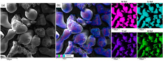
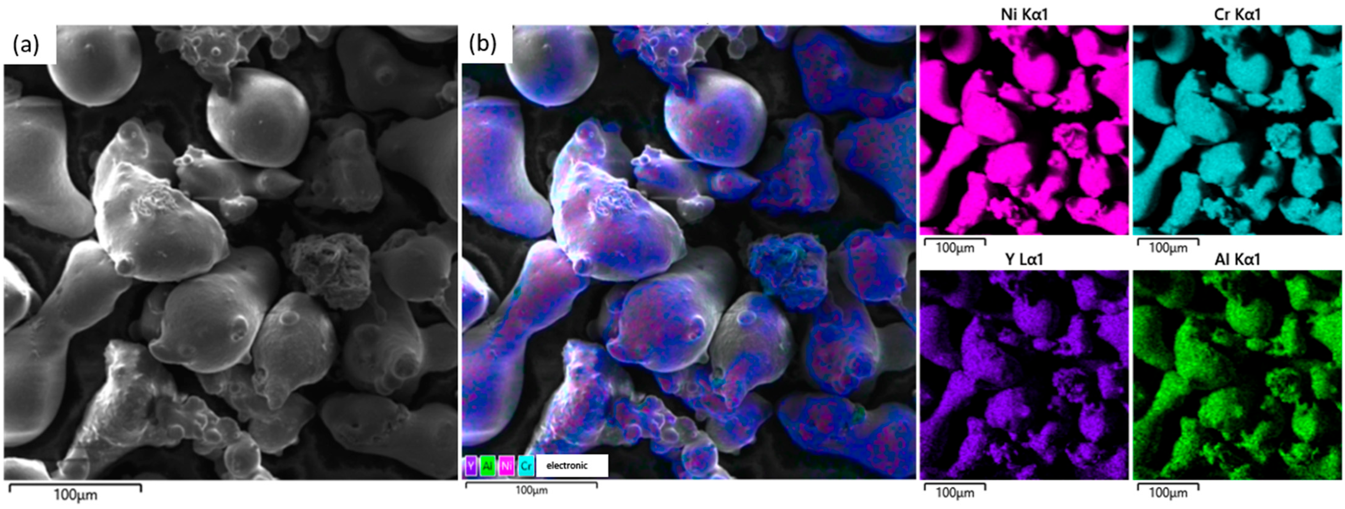
Figure 1a,b show the SEM morphology and elemental energy dispersive spectrometry (EDS) image of NiCrAlY powder. The powder exhibits an irregular morphology with particles of various shapes, including rounded, drop-shaped, and jagged forms, with sizes ranging approximately from 10 to 100 µm (predominantly 30–70 µm). All elements are uniformly distributed in the particles, indicating good homogeneity of the powder. Ni and Cr are predominant, which is typical for heat-resistant alloys. The absence of zones with pure predominance of one element indicates uniform alloying of particles and absence of large intermetallic inclusions.
Figure 1.
Microstructural and elemental analysis: (a) SEM image of powder; (b) EDS analysis of powder.
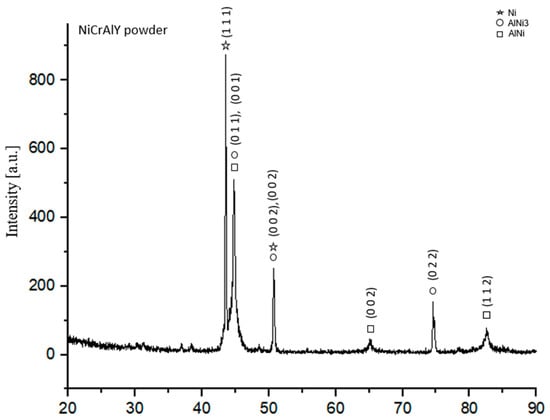
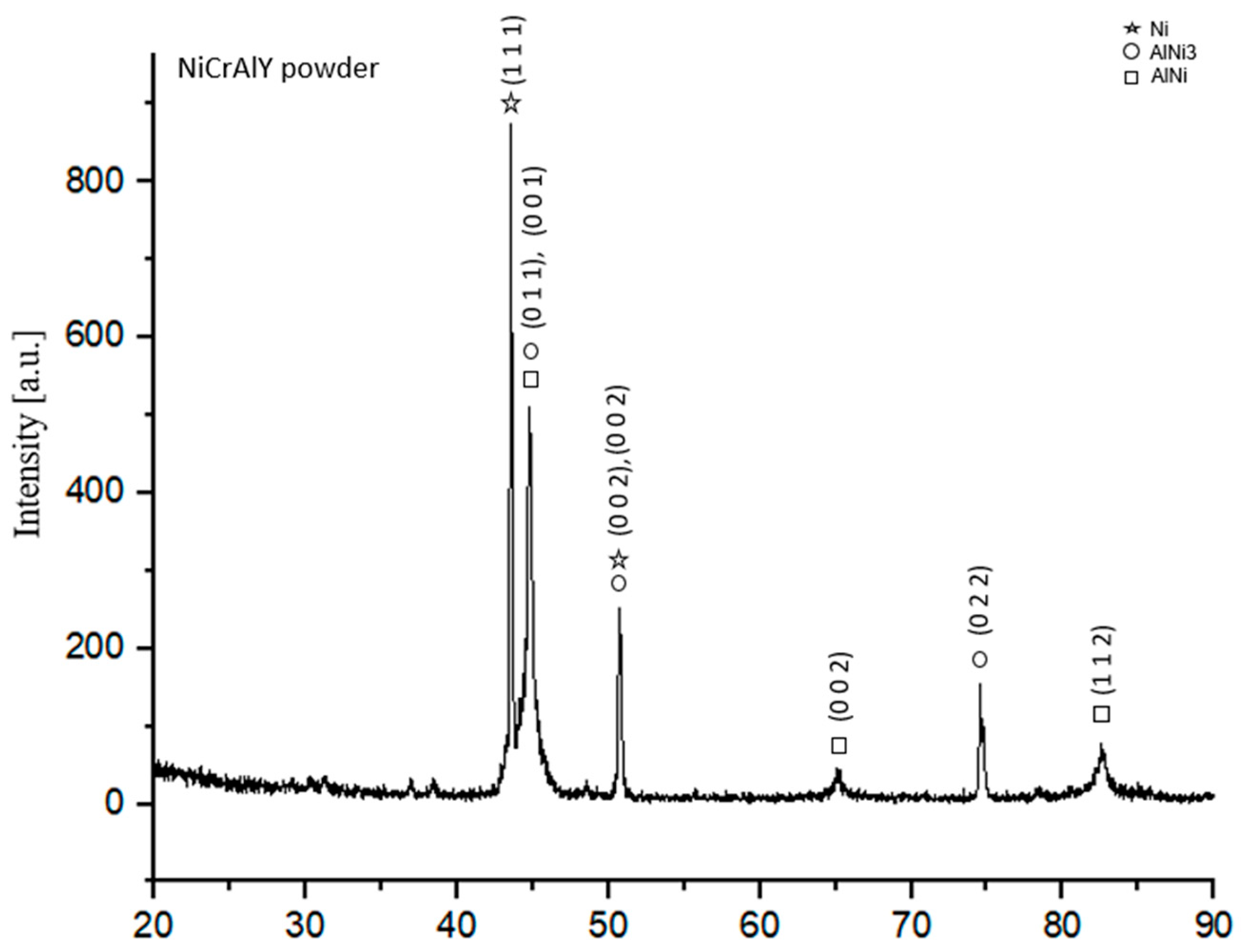
Figure 2 shows the X-ray diffraction patterns of NiCrAlY powder. The phases present were Ni, small amounts of Ni3Al, and AlNi. The diffraction peaks identified in the powder are consistent with those reported in previous studies [15,23]. Ni is the base of the coating, which is resistant to high temperatures [14]. NiAl and Ni3Al provide structural strength and thermal resistance [24]. The NiAl phase is critical for the formation of the aluminum oxide (Al2O3) protective layer, which provides high oxidation resistance at high temperatures [16].
Figure 2.
Results of the X-ray phase analysis of NiCrAlY powder.
3.2. Surface Morphology and Coating Composition
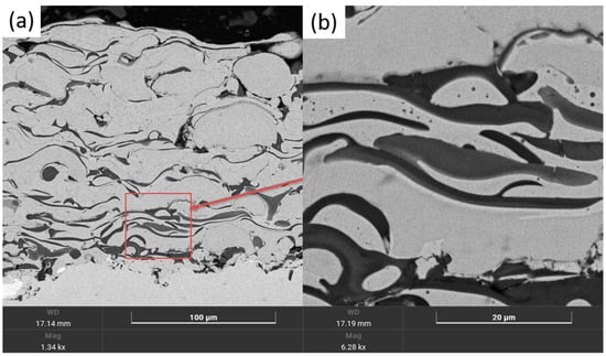
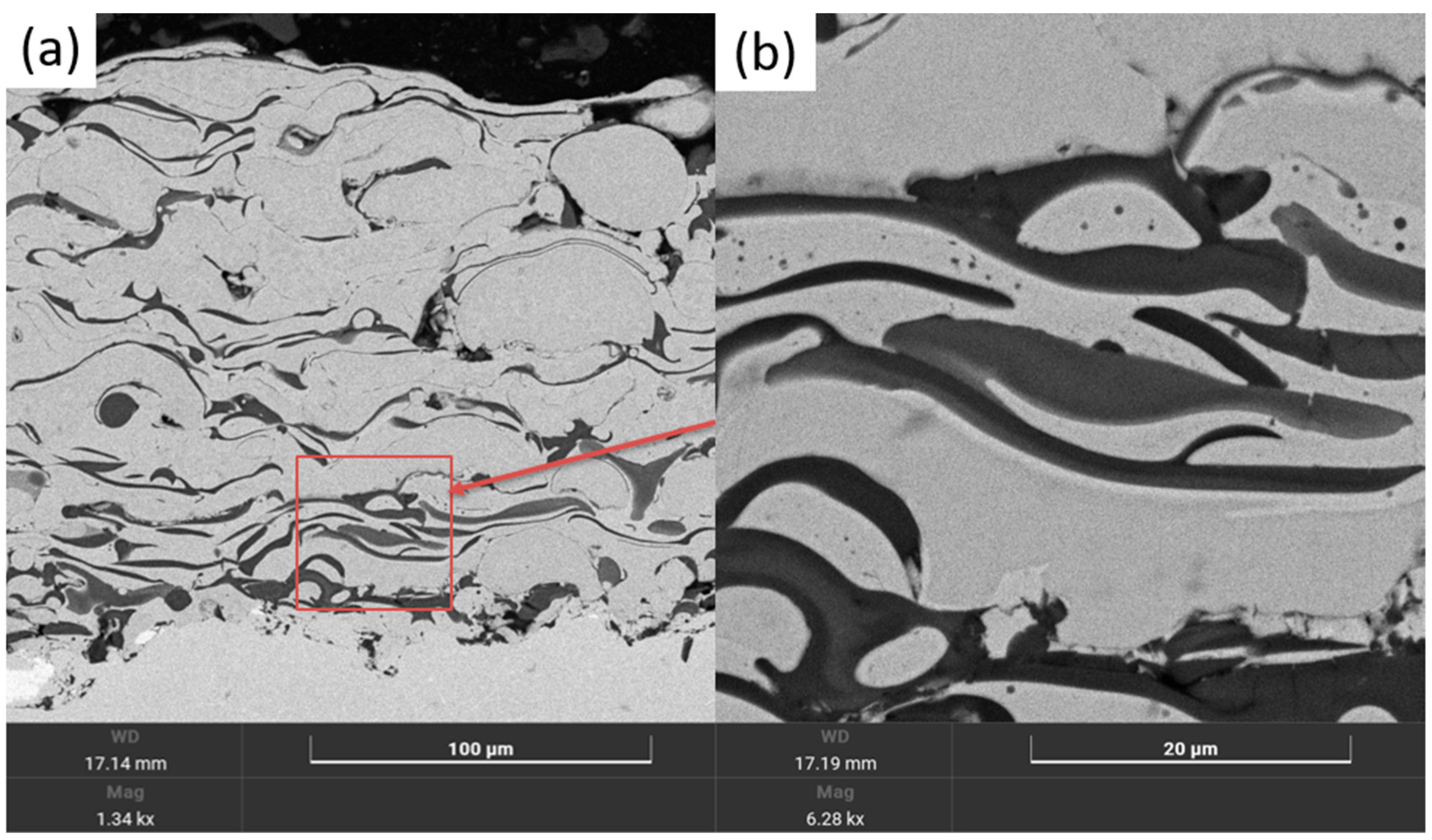
The most dense, low porosity coating with well-melted particles was observed for sample BC_6_8.4 (Figure 3a,b), sprayed at low powder flow rate and optimum spraying power. As can be seen in Figure 3, powder melting occurred efficiently: the NiCrAlY particles are uniformly distributed in the matrix, providing dense interparticle bonding. The pore count is 0.5%, which is lower than the commonly mentioned figure, and the coating itself is characterized by a typical layered structure [25]. The coating is tightly bonded to the substrate, with no obvious cracks. This is due to the fact that the power of the plasma arc provides a sufficient thermal effect that promotes complete or almost complete melting of the powder particles. As a result, their wettability and adhesion both to the substrate and to each other increases. In addition, the low powder feed rate results in less material being applied per unit of time, which in turn allows the particles to melt and set on the surface better.
Figure 3.
SEM cross-sectional images of sample BC_6_8.4: (a) 500× magnification; (b) 3000× magnification.
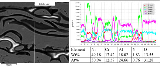
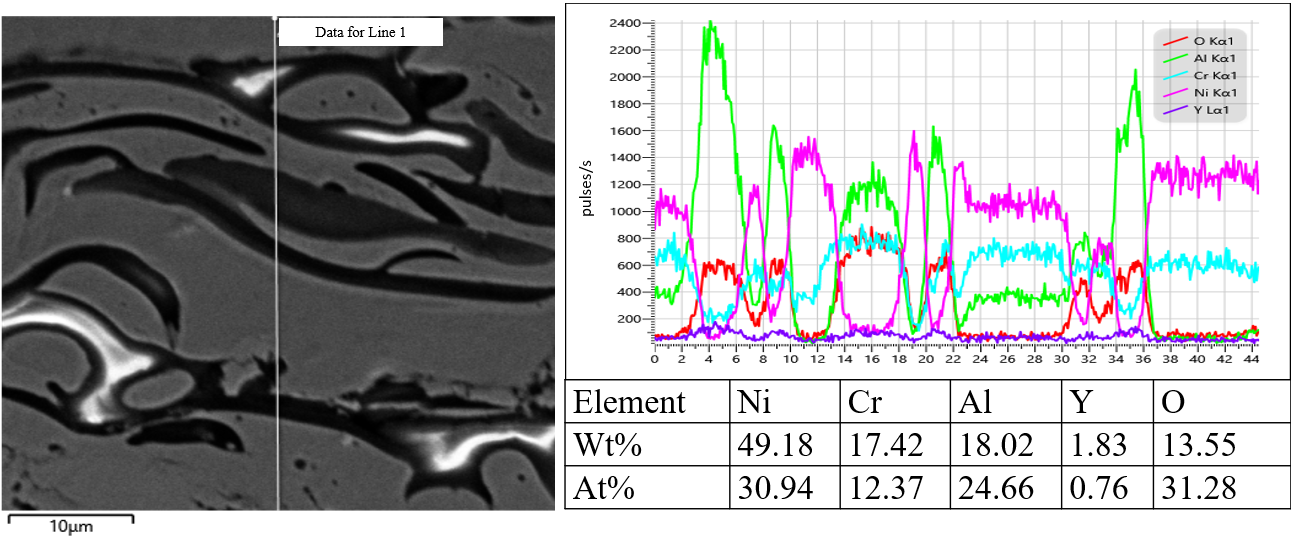
Figure 4 shows the distribution of elements along the cross-sectional line of the coating, from which it follows that nickel is distributed almost uniformly throughout the thickness, and chromium shows even more stable and uniform distribution, indicating the presence of a continuous metal matrix. The elemental composition profile confirms a clearly defined multilayer coating structure with alternating areas of different chemical composition. At the same time, the element aluminum shows itself in the form of periodically repeating peaks, indicating a localized distribution of phases such as Al2O3. The oxygen intensity correlates with the distribution of Al, especially in the zones with its peaks, which confirms the formation of oxide inclusions and indicates the segregation of oxide phases in these areas due to oxidation. No gradual concentration gradient characteristic of a well-developed diffusion zone is observed. This can be explained by the short thermal exposure time during the APS process and the rapid solidification of molten particles, which significantly limits elemental interdiffusion.
Figure 4.
Distribution of elements along the cross-sectional line of cover BC_6_8.4.
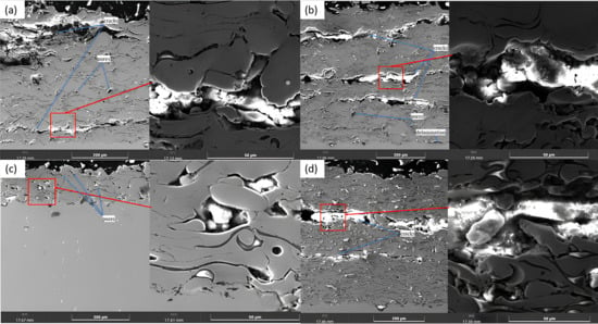
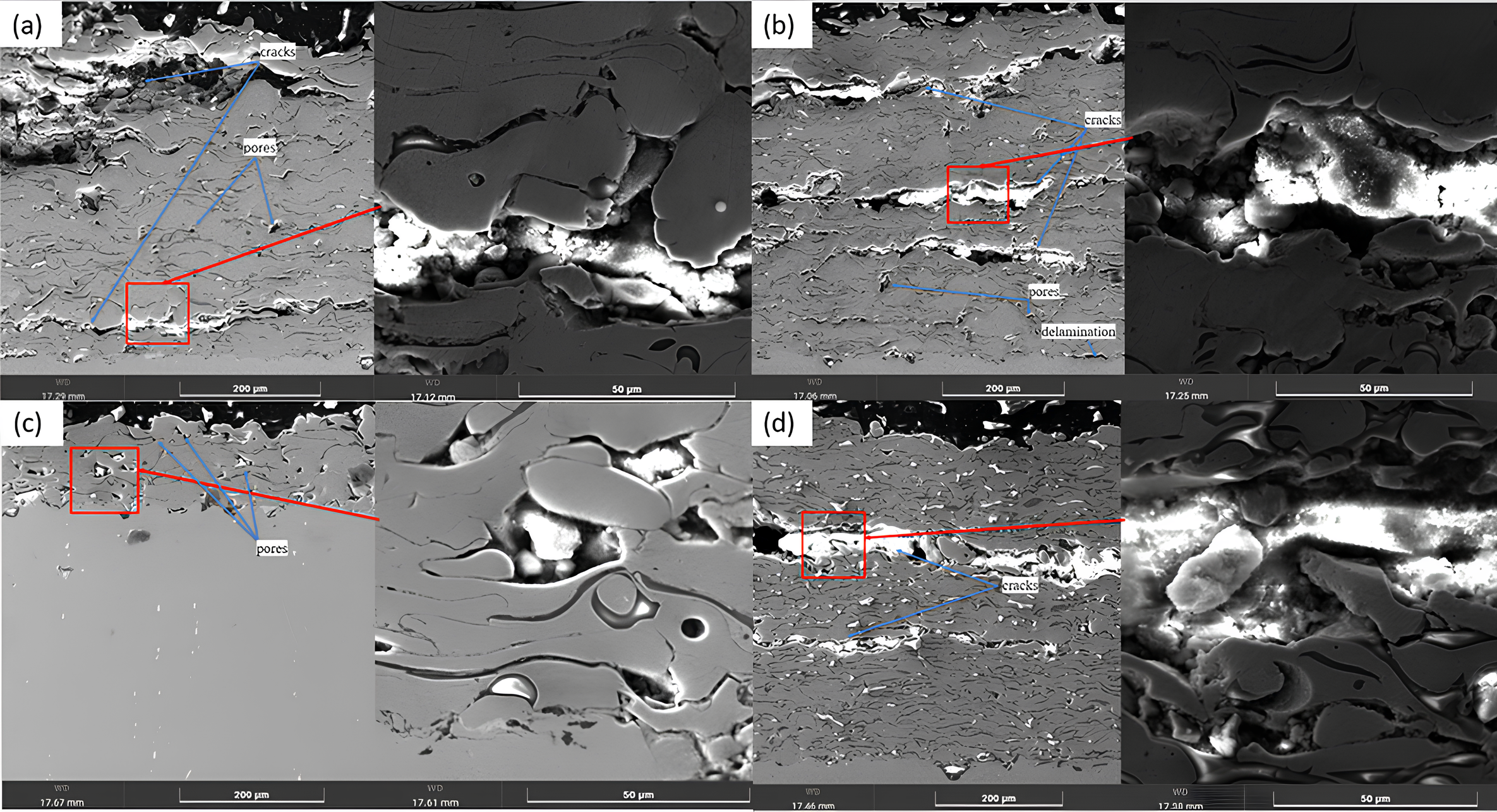
Interlayer cracks can be observed on samples BC_10_8.4, BC_15_8.4, BC_6_4.4, and BC_6_5.9. They are well traced along the boundaries between the sprayed lamellae (Figure 5). And the pulverized particles are separated by interlayer pores formed by rapid solidification of the lamellae, very small voids formed by incomplete contact around the unmelted particles, and cracks that often occur due to weak bonding between the particles. In some places, it is seen that the cracks penetrate deeper into the coating thickness, passing through several layers. This may be caused by thermal stresses due to abrupt cooling after particle deposition. Unmelted or partially melted particles do not bond well with the rest of the coating mass.
Figure 5.
SEM images of the cross-section of samples: (a) BC_10_8.4; (b) BC_15_8.4; (c) BC_6_4.4; (d) BC_6_5.9.
For samples BC_10_8.4 and BC_15_8.4, increasing the powder flow rate leads to the formation of cracks and pores in the coating. This is due to the fact that at increased powder feed, the particles do not have time to melt completely, which leads to poor spreading of particles and formation of micro- and macropores between the layers. Particularly pronounced defects are observed in the middle and lower parts of the coating. In addition, the ingress of semi-solid particles can cause local internal stresses that contribute to delamination and the formation of cracks along the interlamellar boundaries.
The porosity values are presented in Table 3. Localized porosity zones are observed on sample BC_6_4.4, the level of which reaches 2.5%. The coating is characterized by inhomogeneous structure and uneven surface. Porosity can be formed due to unmelted particles also caused by insufficient spraying power. For sample BC_6_5.9, intra-layer pores and cracks are observed in the upper and middle part of the coating. A large longitudinal crack located in the upper part of the coating and running along the lamellar boundaries is particularly prominent. This interlamellar crack is the result of reduced power (current or voltage), which leads to insufficient heating of the particles in the plasma jet. As a result, the particles do not have time to fully melt and do not form dense and well-bonded lamellae upon impact with the substrate. This contributes to the formation of a loose, porous structure in which local stresses easily accumulate, which can initiate and propagate cracks. Several recent studies report relatively high porosity levels for APS coatings. However, in the present study, the BC_6_8.4 coating exhibited significantly lower porosity values, remaining within acceptable industrial standards (<1%) [26,27]. This can be attributed to the optimized atmospheric plasma spraying (APS) parameters, which promoted improved particle melting and the formation of a dense lamellar coating structure.
Table 3.
Effect of spraying parameters on porosity.
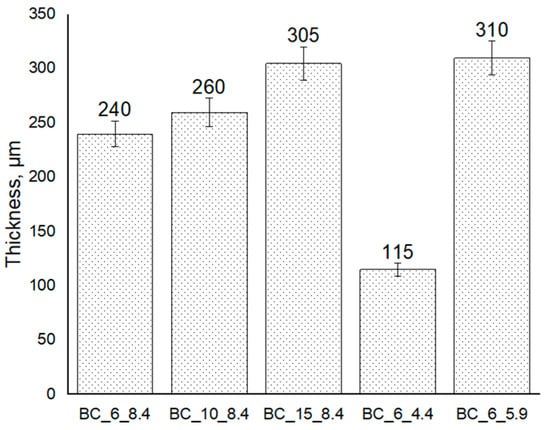
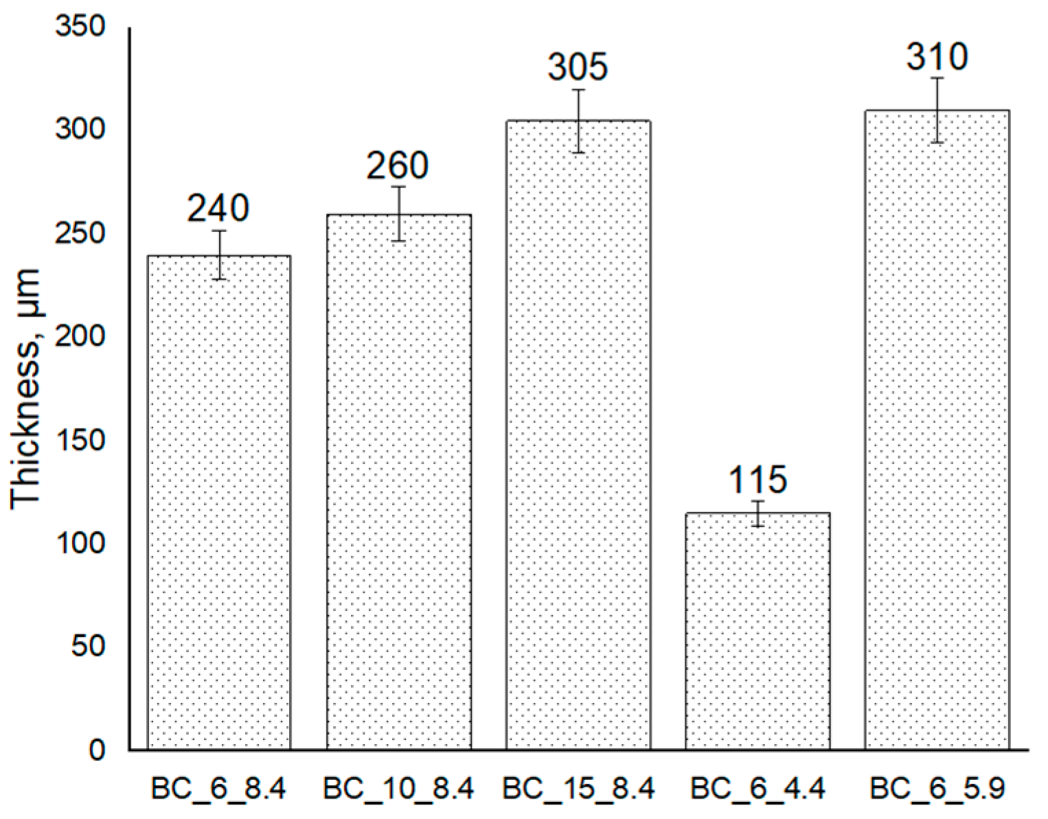
It should be noted that the differences in coating thicknesses observed in Figure 6 are related to the intentional variation of process parameters, namely the powder feed rate and plasma arc power. All coatings were deposited at the same spraying distance (130 mm) and spraying time (60 s); therefore, the thickness variations naturally resulted from differences in material feed and melting efficiency at different power levels. Since the objective of this comparison was to evaluate the effect of process parameters on coating microstructure, porosity, and adhesion strength, the analyses were normalized per unit cross-sectional area and performed at equivalent magnifications to ensure valid comparison among the samples.
Figure 6.
Thickness of coatings deposited under different spraying parameters.
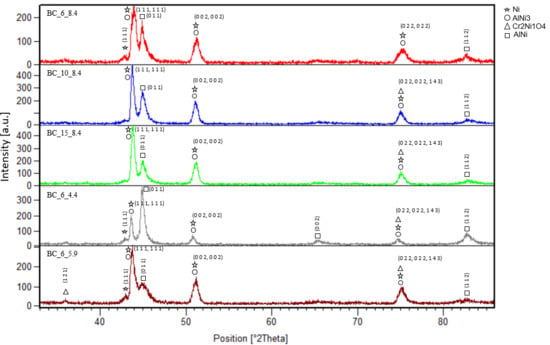
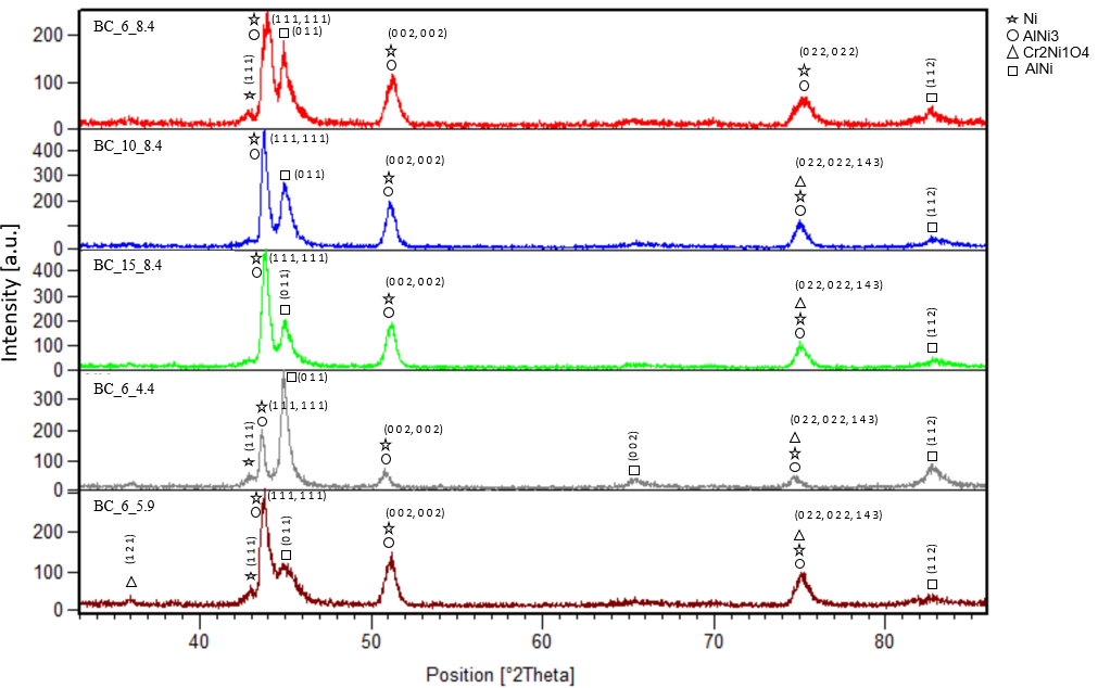
Figure 7 shows the X-ray diffraction patterns of the coating surface. The phases present were Ni, Ni3Al, AlNi, and a small amount of Cr2NiO4.
Figure 7.
Results of the X-ray phase analysis.
With increasing powder feed rate, changes in the relative phase composition are observed, particularly a tendency toward more pronounced Ni3Al reflections in the corresponding diffraction patterns. This indicates that the spraying parameters influence the formation of the intermetallic structure. A comparison of absolute peak intensities among different samples was performed with caution, taking into account differences in the intensity scale.
In the BC_6_8.4 sample, the diffraction peaks are sharper and narrower, suggesting a higher degree of crystallinity and the formation of a more structurally homogeneous coating. In contrast, at reduced spraying power (samples BC_6_4.4 and BC_6_5.9), a relative increase in AlNi reflections and a noticeable broadening of diffraction maxima are observed. This behavior may be associated with insufficient particle melting, disturbance of phase equilibrium, and an increased density of structural defects.
Comparison of the XRD pattern of the initial NiCrAlY powder and the coatings (Figure 2) shows that the powder contains only metallic/intermetallic phases (Ni, Ni3Al, AlNi), whereas the oxide spinel Cr2NiO4 is not present in the starting material. The presence of Cr2NiO4 phases confirms the occurrence of oxidative processes on the surface of coatings BC_6_4.4 and BC_6_5.9. This is explained by the fact that the APS process is carried out in an atmospheric environment, which inevitably leads to partial oxidation of all coatings [28]. This is also associated with the oxidation of fully and partially melted particles, as well as interlamellar boundaries, particularly when particle temperatures are insufficient. Such conditions promote the formation of NiO and its subsequent interaction with Cr2O3, leading to the formation of spinel-type Cr2NiO4. Therefore, the presence of Cr2NiO4 indicates intensified oxidative processes under non-optimal spraying conditions and is undesirable from the standpoint of structural stability and the protective efficiency of the oxide layer.
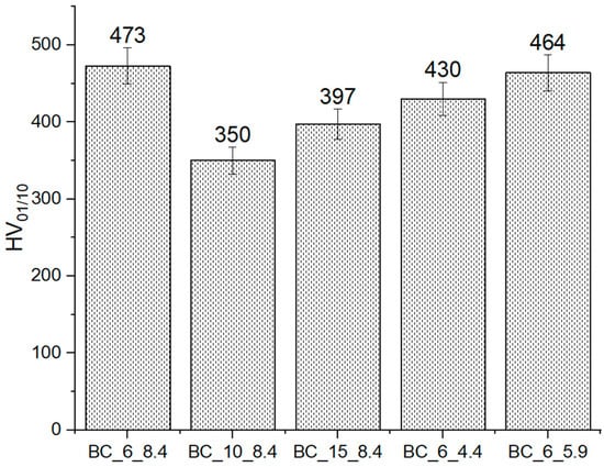
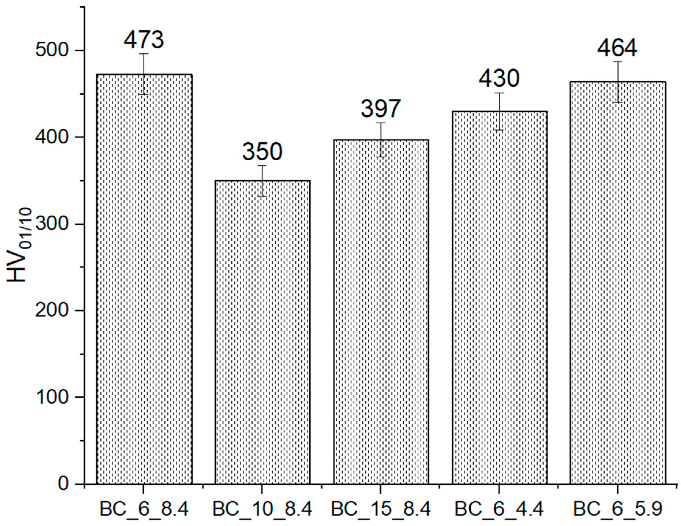
The BC_6_8.4 samples, where the powder flow rate was low, show higher microhardness due to the dense microstructure and good adhesion of the coating to the substrate as the particles have time to melt well and do not overheat.
The hardness of the bonding layer provides its wear resistance and mechanical strength under thermal loads and also serves as a support for the brittle ceramic layer, preventing its cracking and peeling [8]. Figure 8 shows the dependence of hardness on the spraying parameters of the samples. The decrease in hardness of samples BC_10_8.4 and BC_15_8.4 can be attributed to the low density and cracking of the coatings. At high powder flow rates, the plasma jet energy is distributed among a large number of particles, resulting in many of them remaining semi-molten or not cold at all. This results in poor particle flattening and poor interlayer bonding and defects, which in turn reduces the microhardness of the coating. Reducing the spraying power in BC_6_4.4, BC_6_5.9 coatings led to a decrease in the coating hardness, which is also attributed to the weak degree of particle flattening, poor interlayer bonding, and formation of structural defects. Moreover, too low energy promotes worse penetration into the substrate roughness [29].
Figure 8.
Hardness dependence on spraying mode.
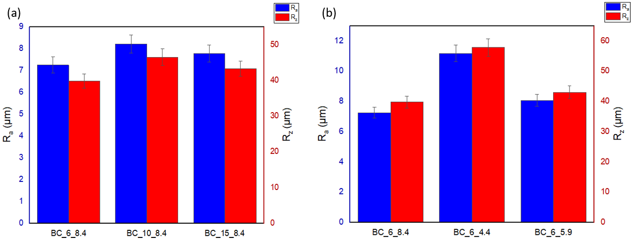
The sample BC_6_8.4 obtained at a low powder feed rate and optimal spraying power showed lower values of roughness parameters Ra and Rz (Figure 9). However, the coatings BC_10_8.4, BC_15_8.4, BC_6_4.4, and BC_6_5.9, despite their relatively high roughness, are characterized by higher particle temperatures and less uniform particle distribution, which leads to the formation of a pronounced surface microrelief.
Figure 9.
Values of surface roughness parameter Ra and Rz as a function of: (a) powder flow rate; (b) spraying power.
Although roughness is higher, adhesion is impaired due to increased porosity and reduced coating density [30]. Excessively sharp irregularities can act as stress concentrators during thermal cycling, leading to localized cracking of the ceramic top layer at roughness peaks [31]. When coatings are sprayed onto rough surfaces, variations in coating thickness occur, which reduce thermal resistance and durability [32]. As a result, the thermal insulation performance may deteriorate. If the surface is too rough, the ceramic layer may deposit unevenly, leaving voids and pores, which compromises the coating’s tightness and durability [33].
Samples BC_6_8.4 are characterized by a denser microstructure and a uniform surface, which is due to good particle melting, minimal deformation, and a high degree of flattening. Such bonding layers contribute to the formation of a more uniform columnar structure of the top coating, which can have a positive effect on its heat-shielding properties. This is especially important for use in high-temperature conditions. The coating roughness exceeds 3 µm, which meets the requirements for bonding layers and ensures reliable adhesion with subsequent coatings [34].
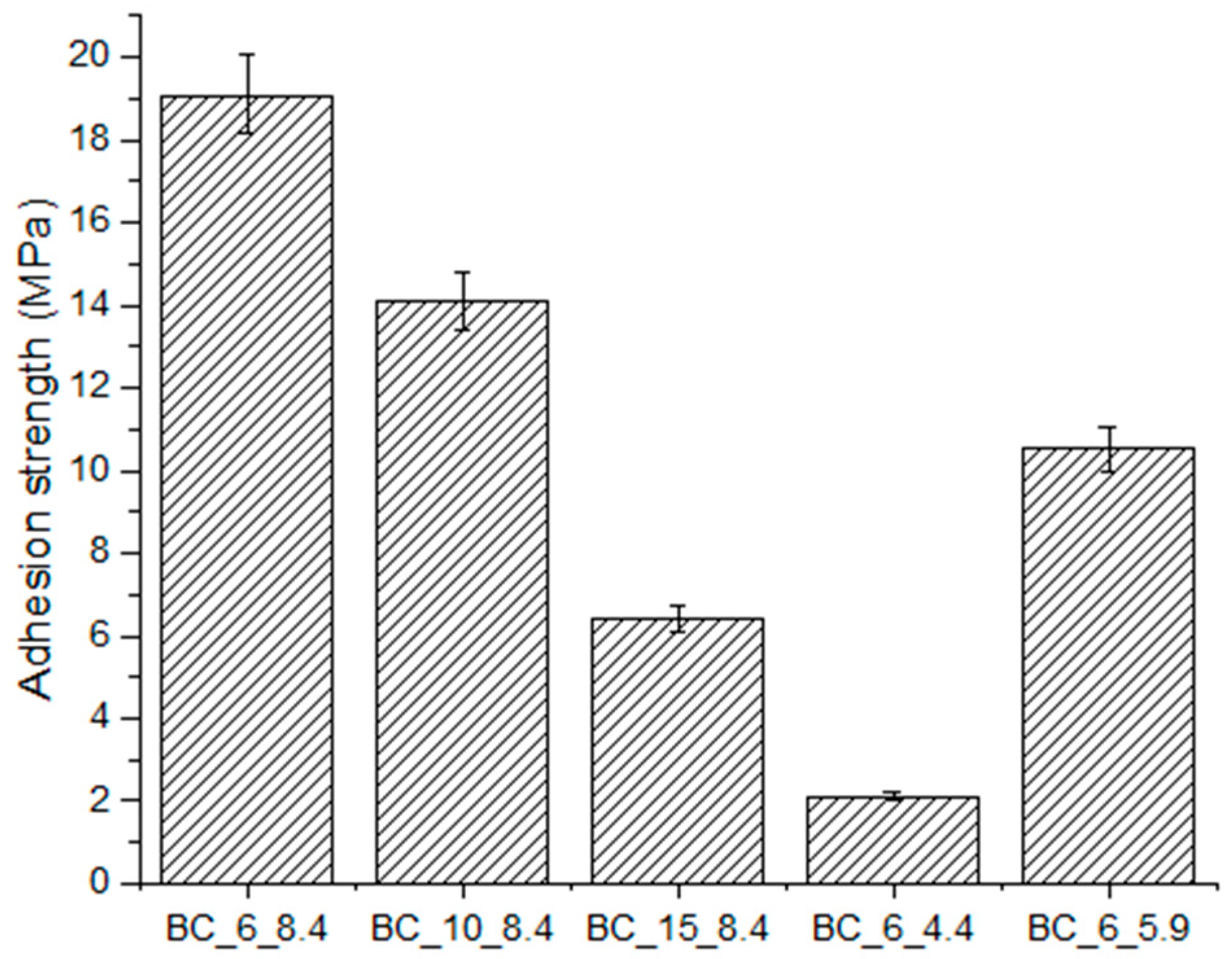
Figure 10 shows the adhesive bond strength of all the samples. The results showed that sample BC_6_8.4 showed an increase in adhesion bond strength compared with other samples. From the results, it is observed that the coating adhesion increases with decreasing powder consumption and increasing power. Other specimens fail at 2.11 MPa, whereas specimen BC_6_8.4 fails up to 19.09 MPa.
Figure 10.
Adhesion strength of the samples.
This indicates that the spraying mode used to obtain the BC_6_8.4 coating significantly improves the adhesion strength between the coating and the substrate. Sample BC_6_8.4 shows higher adhesion strength compared with the other samples. The low adhesion strength values of the other coatings are probably due to the presence of defects in the coating structure. If the particle temperature was insufficient (due to lower current or voltage or excessively high powder feed rate), the particles may not have melted completely, not spreading properly and consequently not providing a reliable bond to the substrate surface. The increased adhesion strength of BC_6_8.4 is due to improved interparticle bonding in the coating itself, as well as a more secure bond to the substrate, as evidenced by its cross-section (Figure 3a).
According to the literature [26], high adhesion is achieved at low coating porosity, which is consistent with the BC_6_8.4 sample, as increased porosity reduces the bonding strength between layers.
Thus, although the power of 8.4 kW is not typical for NiCrAlY coatings produced by the APS method according to the literature data, within the framework of the present study, it was this power, in combination with a low powder feed rate, that made it possible to obtain a coating with optimal structural and mechanical characteristics ensuring preservation of the β-NiAl phase, controlled porosity, and sufficient adhesion strength, providing the properties necessary for the reliable performance of the bond coat in a thermal barrier coating (TBC) system [35]. It is known that a mismatch between power and material feed rate can negatively affect the coating structure and its performance properties [36]. However, in this case, the selection of a power level adequate to the low powder feed rate contributed to the reduction of particle overheating and, consequently, to the prevention of aluminum evaporation—one of the key elements ensuring the formation of the protective oxide phase Al2O3, as confirmed by the preservation of the NiAl intermetallic phase according to X-ray diffraction analysis.
Thus, the durability of NiCrAlY coatings is determined by the density and uniformity of the lamellar structure, low porosity, minimal microcracking, and high adhesion strength to the substrate. Increased porosity, the formation of oxide spinel phases, and structural defects reduce the overall coating quality. Therefore, optimization of spraying parameters is a key factor in ensuring the long-term operational reliability of the coating.
4. Conclusions
The present study has shown that air plasma spraying parameters such as powder flow rate and plasma arc power have a significant effect on the microstructure, phase composition, bond strength, hardness, and porosity of NiCrAlY bonded coatings deposited on Inconel 718 alloy substrate.
The spraying mode with low powder feed rate and high plasma power (sample BC_6_8.4) was found to be optimal. The resulting coating exhibited uniform melting of particles and homogeneous deposition, forming a dense lamellar structure with a low level of microcracks. The relatively mild spraying conditions helped minimize oxidation, where oxygen was mainly localized along the boundaries of flattened particles, without the formation of excess Cr2O3, which could otherwise reduce adhesion.
According to the microstructural analysis, the coating produced at 8.4 kW showed low porosity (0.5%) and almost no interlamellar defects, distinguishing it favorably from coatings obtained at higher powers. This spraying regime provided the maximum adhesion strength of 19.09 MPa, which significantly exceeded that of other samples (2.11 MPa). Such improvement is attributed to complete particle melting, enhanced interparticle bonding, uniform particle distribution, and reliable contact with the substrate.
The results demonstrate that precise adaptation of spraying parameters to a specific equipment configuration and powder feed mode can provide improved coating properties even when atypical power values are used.
Author Contributions
A.K. (Aidar Kengesbekov): Conceptualization, validation, data curation; B.R.: conceptualization, methodology, writing—review and editing; N.M.: methodology, validation, writing—review and editing, supervision; I.A.: visualization, investigation, writing—original draft preparation; A.K. (Arystanbek Kussainov): formal analysis, investigation; S.A.: validation, formal analysis, data curation, writing—review and editing. All authors have read and agreed to the published version of the manuscript.
Funding
This research was funded by the Science Committee of the Ministry of Education and Science of the Republic of Kazakhstan (Grant N AP23489951).
Data Availability Statement
The original contributions presented in this study are included in the article. Further inquiries can be directed to the corresponding authors.
Conflicts of Interest
Author Bauyrzhan Rakhadilov was employed by the company PlasmaScience LLP. The remaining authors declare that the research was conducted in the absence of any commercial or financial relationships that could be construed as a potential conflict of interest.
Abbreviations
The following abbreviations are used in this manuscript:
| TBC | Thermal Barrier Coating |
| TGO | Thermally grown oxide |
| YSZ | Yttrium-stabilized zirconia |
| NiCrAlY | Nickel–chromium–aluminum–yttrium |
| APS | Atmospheric Plasma Spraying |
| HVOF | High-velocity oxygen fuel |
| EB-PVD | Electron beam physical vapor deposition |
| EDS | Energy dispersive spectrometry |
References
- Bäker, M.; Fiedler, T.; Rösler, J. Stress evolution in thermal barrier coatings for rocket engine applications. Mech. Adv. Mater. Mod. Process 2015, 1, 5. [Google Scholar] [CrossRef] [Scilit]
- Fassin, M.; Wulfinghoff, S.; Reese, S. Modelling Thermal Barrier Coatings and Their Influence on the Lifetime of Rocket Engine Nozzle Structures. In Proceedings of the VII European Congress on Computational Methods in Applied Sciences and Engineering (ECCOMAS Congress 2016); Institute of Structural Analysis and Antiseismic Research School of Civil Engineering National Technical University of Athens (NTUA) Greece: Crete Island, Greece, 2016; pp. 6764–6773. [Google Scholar] [CrossRef] [Scilit]
- Ozgurluk, Y.; Karaoglanli, A.C.; Ahlatci, H. Comparison of calcium magnesium-alumina-silicate (cmas) resistance behavior of produced with electron beam physical vapor deposition (eb-pvd) method ysz and Gd2Zr2O7/ysz thermal barrier coatings systems. Vacuum 2021, 194, 110576. [Google Scholar] [CrossRef] [Scilit]
- Jaf, Z.N.; Jiang, Z.-T.; Miran, H.A.; Altarawneh, M.; Veder, J.-P.; Minakshi, M.; Zhou, Z.-F.; Lim, H.; Huang, N.; Dlugogorski, B.Z. Physico-chemical properties of CrMoN coatings—Combined experimental and computational studies. Thin Solid. Film. 2020, 693, 137671. [Google Scholar] [CrossRef] [Scilit]
- Karaoglanli, A.; Altuncu, E.; Ozdemir, I.; Turk, A.; Ustel, F. Structure and durability evaluation of YSZ+Al2O3 composite TBCs with APS and HVOF bond coats under thermal cycling conditions. Surf. Coat. Technol. 2011, 205, S369–S373. [Google Scholar] [CrossRef] [Scilit]
- Buitkenov, D.; Rakhadilov, B.; Nabioldina, A.; Mukazhanov, Y.; Adilkanova, M.; Raisov, N. Investigation of Structural Phase, Mechanical, and Tribological Characteristics of Layer Gradient Heat-Protective Coatings Obtained by the Detonation Spraying Method. Materials 2024, 17, 5253. [Google Scholar] [CrossRef] [Scilit]
- Lavasani, H.Q.; Valefi, Z.; Ehsani, N.; Masoule, S.T. Studying the effect of spraying parameters on the sintering of YSZ TBC using APS method. Surf. Coat. Technol. 2019, 360, 238–246. [Google Scholar] [CrossRef] [Scilit]
- Bogdan, M.; Peter, I. A Comprehensive Understanding of Thermal Barrier Coatings (TBCs): Applications, Materials, Coating Design and Failure Mechanisms. Metals 2024, 14, 575. [Google Scholar] [CrossRef] [Scilit]
- Feng, Y.; Dong, T.-S.; Li, G.-L.; Wang, R.; Zhao, X.-W.; Liu, Q. High temperature oxidation resistance and TGO growth mechanism of laser remelted thermal barrier coatings. J. Alloys Compd. 2020, 828, 154266. [Google Scholar] [CrossRef] [Scilit]
- Lima, R.S. Porous APS YSZ TBC Manufactured at High Powder Feed Rate (100 g/min) and Deposition Efficiency (70%): Microstructure, Bond Strength and Thermal Gradients. J. Therm. Spray Technol. 2022, 31, 396–414. [Google Scholar] [CrossRef] [Scilit]
- Rajasekaran, B.; Mauer, G.; Vaßen, R. Enhanced Characteristics of HVOF-sprayed MCrAlY Bond Coats for TBC Applications. J. Therm. Spray Technol. 2011, 20, 1209–1216. [Google Scholar] [CrossRef] [Scilit]
- Gong, S.; Wu, Q. Processing, microstructures and properties of thermal barrier coatings by electron beam physical vapor deposition (EB–PVD). In Thermal Barrier Coatings; Elsevier: Amsterdam, The Netherlands, 2011; pp. 115–131. [Google Scholar] [CrossRef] [Scilit]
- Qu, W.; Chen, Z.; Zhang, Z.; Li, X.; Yang, F.; Wang, J.; Chen, M.; Li, S.; Wang, F. Characteristics and hot corrosion behavior of NiCrAlY metal bonding layers prepared by different processes. npj Mater. Degrad. 2024, 8, 36. [Google Scholar] [CrossRef] [Scilit]
- Zheng, J.; Yang, D.; Gao, Y. Effect of Vacuum Heat Treatment on the High-Temperature Oxidation Resistance of NiCrAlY Coating. Coatings 2020, 10, 1089. [Google Scholar] [CrossRef] [Scilit]
- Li, B.; Ma, S.; Gao, Y.; Li, C.; Guo, H.; Zheng, Q.; Kang, Y.; Jia, J. Mechanical, Tribological, and Oxidation Resistance Properties of NiCrAlY Coating by Atmospheric Plasma Spraying. Front. Mater. 2019, 6, 67. [Google Scholar] [CrossRef] [Scilit]
- Jahromi, M.G.; Razavi, R.S.; Valefi, Z.; Naderi-Samani, H.; Taghi-Ramezani, S. Evaluating laser surface melting of NiCrAlY-APS coating and its effect on high-temperature oxidation behavior of NiCrAlY/YSZ thermal barrier coating before and after surface melting. Heliyon 2023, 9, e23094. [Google Scholar] [CrossRef] [Scilit] [PubMed]
- Abbas, R.A.; Ajeel, S.A.; Bash, M.A.A.; Kadhim, M.J. Effect of plasma spray distance on the features and hardness reliability of YSZ thermal barrier coating. Mater. Today Proc. 2021, 42, 2553–2560. [Google Scholar] [CrossRef] [Scilit]
- Chen, Y.; Wang, G.; Zhang, H. Numerical simulation of coating growth and pore formation in rapid plasma spray tooling. Thin Solid. Film. 2001, 390, 13–19. [Google Scholar] [CrossRef] [Scilit]
- Kengesbekov, A.; Rakhadilov, B.; Sagdoldina, Z.; Buitkenov, D.; Dosymov, Y.; Kylyshkanov, M. Improving the Efficiency of Air Plasma Spraying of Titanium Nitride Powder. Coatings 2022, 12, 1644. [Google Scholar] [CrossRef] [Scilit]
- Gao, F.; Huang, X.; Liu, R.; Yang, Q. Optimization of Plasma Spray Process Using Statistical Methods. J. Therm. Spray Technol. 2012, 21, 176–186. [Google Scholar] [CrossRef] [Scilit]
- ASTM E2109-01; Standard Test Methods for Determining Area Percentage Porosity in Thermal Sprayed Coatings. ASTM International: West Conshohocken, PA, USA, 2021.
- ASTM C633-13; Standard Test Method for Adhesion or Cohesion Strength of Thermal Spray Coatings. ASTM International: West Conshohocken, PA, USA, 2021.
- Hebbale, A.M.; Ramesh, M.; Petru, J.; Chandramouli, T.; Srinath, M.; Shetty, R.K. A microstructural study and high-temperature oxidation behaviour of plasma sprayed NiCrAlY based composite coatings. Results Eng. 2025, 25, 103926. [Google Scholar] [CrossRef] [Scilit]
- Vijay, V.A.; Santhy, K.; Sivakumar, G.; Rajasekaran, B. Thermal Expansion and Microstructure Evolution of Atmospheric Plasma Sprayed Nicraly Bond Coat Using In-Situ High Temperature X-Ray Diffraction. Surf. Coat. Technol. 2022, 452, 129132. [Google Scholar] [CrossRef] [Scilit]
- Tillmann, W.; Khalil, O.; Abdulgader, M. Porosity Characterization and Its Effect on Thermal Properties of APS-Sprayed Alumina Coatings. Coatings 2019, 9, 601. [Google Scholar] [CrossRef] [Scilit]
- Karthikeyan, S.; Raja, S.; Balasubramanian, V.; Yishak, S. Evaluation of microstructure and mechanical properties of thermally sprayed NiCrAlY bond coats on Superni C-263 aero engine combustor liner alloy. Results Eng. 2025, 26, 105060. [Google Scholar] [CrossRef] [Scilit]
- Karthikeyan, S.; Subramani, R.; Balasubramanian, V.; Yishak, S. Effects of thermal spray processes on the development microstructure and thermal properties of NiCrAlY bond coats deposited over superni C-263 aero engine combustor liner alloy. Mater. Res. Express 2025, 12, 076511. [Google Scholar] [CrossRef] [Scilit]
- Hejrani, E.; Sebold, D.; Nowak, W.; Mauer, G.; Naumenko, D.; Vaßen, R.; Quadakkers, W. Isothermal and cyclic oxidation behavior of free standing MCrAlY coatings manufactured by high-velocity atmospheric plasma spraying. Surf. Coat. Technol. 2017, 313, 191–201. [Google Scholar] [CrossRef] [Scilit]
- Hongyu, Q.; Xiaoguang, Y.; Yamei, W. Interfacial fracture toughness of APS bond coat/substrate under high temperature. Int. J. Fract. 2008, 157, 71–80. [Google Scholar] [CrossRef] [Scilit]
- Sul, I.H.; Hong, K.H.; Kang, T.J. Surface Roughness Measurement of Nonwovens Using 3d Profile Data; SAGE: Thousand Oaks, CA, USA, 2006. [Google Scholar]
- Maciaszek, G.; Nowotnik, A. Influence of Bond Coat Roughness on Adhesion of Thermal Barrier Coatings Deposited by the Electron Beam–Physical Vapour Deposition Process. Appl. Sci. 2024, 14, 7401. [Google Scholar] [CrossRef] [Scilit]
- Wei, Z.-Y.; Cai, H.-N.; Zhao, S.-D. Study on spalling mechanism of APS thermal barrier coatings considering surface vertical crack evolution affected by surrounding cracks. Ceram. Int. 2022, 48, 11445–11455. [Google Scholar] [CrossRef] [Scilit]
- Nowak, W.; Naumenko, D.; Mor, G.; Mor, F.; Mack, D.; Vassen, R.; Singheiser, L.; Quadakkers, W. Effect of processing parameters on MCrAlY bondcoat roughness and lifetime of APS–TBC systems. Surf. Coat. Technol. 2014, 260, 82–89. [Google Scholar] [CrossRef] [Scilit]
- Ghumatkar, A.; Budhe, S.; Sekhar, R.; Banea, M.D.; de Barros, S. Influence of Adherend Surface Roughness on the Adhesive Bond Strength. Lat. Am. J. Solids Struct. 2016, 13, 2356–2370. [Google Scholar] [CrossRef] [Scilit]
- Senderowski, C.; Vigilianska, N.; Burlachenko, O.; Grishchenko, O.; Murashov, A.; Stepanyuk, S. Effect of APS Spraying Parameters on the Microstructure Formation of Fe3Al Intermetallics Coatings Using Mechanochemically Synthesized Nanocrystalline Fe-Al Powders. Materials 2023, 16, 1669. [Google Scholar] [CrossRef] [Scilit] [PubMed]
- Li, C.-J.; Yang, G.-J. Relationships between feedstock structure, particle parameter, coating deposition, microstructure and properties for thermally sprayed conventional and nanostructured WC–Co. Int. J. Refract. Met. Hard Mater. 2013, 39, 2–17. [Google Scholar] [CrossRef] [Scilit]

Disclaimer/Publisher’s Note: The statements, opinions and data contained in all publications are solely those of the individual author(s) and contributor(s) and not of MDPI and/or the editor(s). MDPI and/or the editor(s) disclaim responsibility for any injury to people or property resulting from any ideas, methods, instructions or products referred to in the content. |
© 2026 by the authors. Licensee MDPI, Basel, Switzerland. This article is an open access article distributed under the terms and conditions of the Creative Commons Attribution (CC BY) license.