


Abstract
In this study, three distinct microstructures of the metastable β alloy Ti-5Cr-5Mo-5V-4Al-1Nb (Ti55541), characterized by inhomogeneity, heterogeneity, and hierarchical features, were tailored through hot isostatic pressing (HIP) and post-HIP heat treatments. The phase constitution, microstructural evolution, tensile properties, and impact toughness of the Ti55541 HIP compacts were comprehensively investigated. In general, the extensive α/β interfaces, particularly those associated with prior particle boundary α (αPPB-2) and grain boundary α (αGB) phases, acted as preferential sites for crack initiation, imposing adverse impacts on both strength and toughness. Among the microstructures examined, the hierarchical arrangement of fine secondary α (αS) laths combined with arrays of grain-boundary Widmanstatten α (αWGB) exhibited the most favorable combination of mechanical properties, with an ultimate tensile strength of ~1355 MPa, a total elongation of ~8.0%, and an impact toughness of ~26.0 J·cm−2.
1. Introduction
Since β-titanium alloys were established as a distinct class by Jaffee in 1955, a wide range of alloying elements have been explored to enhance their performance, driving substantial early-stage research activity on this alloy system [1,2,3,4]. Among the various categories of titanium alloys, near-β and metastable-β types are particularly well-regarded for aerospace applications due to their exceptional combination of strength and toughness [5,6]. Mo, V, and Nb are mainly isomorphous β phase stabilizers, which are helpful for the expansion of the β phase field. Meanwhile, both Fe and Cr tend to promote the eutectoid reaction between the β matrix and ordered intermetallic compounds. All of the aforementioned alloying elements are conducive to lowering the β-transus temperature. Additionally, increasing additions of Nb have been shown to improve the resistance to crack propagation by promoting dislocation mobility [7,8,9,10,11]. Based on established classification criteria, the molybdenum equivalent (MoE) was calculated under conditions that ensure retention of the β phase with the minimum content of the ω phase. As a promising metastable β-titanium alloy, Ti55541 exhibits a MoE of approximately 18, and was originally designed for the airframe of next-generation unmanned aerial vehicles (UAVs) [12].
Notably, the yield strength of the wrought β-solutioned Ti55541 alloy outperforms that of most titanium alloys strengthened by stress-induced α″ martensite [13]. The typical microstructure of the Ti55541 alloy after forging consists of approximately 24 vol% equiaxed primary α (αP) and equiaxed β phase grains [14,15]. Fu et al. [16,17] reported that the combination of equiaxed and lamellar αP, together with lenticular secondary α (αS), is optimal for plasticity. In addition, the microstructural configuration comprising grain-boundary Widmanstatten α (αWGB), grain-boundary α (αGB), and lenticular αS exhibited promising fracture and impact toughness values. Zhang et al. [18] reported that, in rapidly heated Ti55541 alloy, an appropriate amount of ω-assisted nucleation can suppress the growth of continuous αGB films and refine intragranular α laths, which improves plasticity without sacrificing strength. Xiang et al. [19] found that as the aging temperature was increased from 510 °C to 540 °C in 10 °C increments, the average width of the αS phase increased from 60 nm to 140 nm. Yang et al. [20] conducted a comparative study between laser direct energy deposition (LDED) and wrought Ti55541 alloy. In the solution-treated LDED samples, high-density dislocations were present as sub-grain boundaries enriched in Cr and O but depleted in Mo. Dislocations in the LDED alloy tended to pile up at semi-coherent α/β interfaces, whereas those in the wrought alloy were distributed both within the α and β phases. It should be noted that the majority of research on the Ti55541 alloy has focused on conventional casting and forging routes [21,22,23,24]. However, as is well known, the relatively high work-hardening rate of metastable β-titanium alloys poses a limitation for conventional subtractive manufacturing, leading to a low buy-to-fly ratio and substantially increased economic costs for geometrically complex aerospace components.
Hot isostatic pressing (HIP), as a primary near-net-shaping (NNS) technique, enables the fabrication of fully dense and geometrically complex components [25]. Among titanium alloy HIP compacts, the microstructural characteristics and mechanical strength of Ti-6Al-4V alloys have been extensively investigated and developed [26,27,28,29]. Cao et al. [30] proposed that isostatic pressure reduces the β-transus temperature by approximately 0.08 K/MPa, based on the Clausius–Clapeyron effect. Given the limited precipitation of the α phase in one-step as-HIPed Ti5553 alloy, Perevoshchikova et al. [31] devised a three-step HIP protocol to enhance the α phase volume fraction, promoting dislocation accumulation through the formation of the ω phase acting as heterogeneous nucleation sites. Dekhtyar et al. [32] reported the presence of helical dislocations dissociated across three planes of the α phase over relatively large widths (approximately 30–40 nm) in Ti5553 alloy, which was attributed to the low stacking fault energy of this alloy system. In Ti-25V-15Cr-2Al-0.2C HIP compacts, Ti2C carbides tend to precipitate and disperse both at grain boundaries and within grain interiors [33]. The non-uniform distribution of these fine carbides has been shown to promote void nucleation, ultimately leading to the formation of dimples on the fracture surface.
To the best of the authors’ knowledge, studies on the metastable β-titanium alloy Ti55541 HIP compacts remain limited, and the quantitative relationship between HIP-induced microstructural features and fracture toughness has not been systematically established. In particular, the roles of prior particle boundaries, multi-scale α-Precipitation, and grain-boundary characteristics in governing strength and toughness remain unclear. To address this gap, the present work designs three distinct microstructures—inhomogeneous, heterogeneous, and hierarchical—via HIP and post-HIP heat treatments, and quantitatively decouples partitional contributions. The strength–toughness synergy and fracture mechanisms associated with the different microstructures are discussed in terms of both crack initiation and propagation as well.
2. Experimental Method
2.1. Materials Preparation
The Ti-5Cr-5Mo-5V-4Al-1Nb powder was produced from pre-alloyed electrodes via the Supreme Speed Plasma Rotating Electrode Process (SS-PREP®) at a rotation speed of approximately 30,000 RPM. The particle size distribution of the sieved powder ranged from 25 to 150 μm in diameter, exhibiting a Gaussian distribution (D50 = 102.6 μm), with a Hall flowability of 24 s per 50 g. The spherical morphology and cross-sectional microstructure of the powders are shown in Figure S1. Owing to the rapid cooling rate of 103–104 °C/s inherent to the SS-PREP [34], a triplex microstructure was clearly observed: cellular β sub-grains in the powder core, dendritic β sub-grains and martensitic α’ (0.2–3.6 μm) near the rim [35].
As for the HIP process, 8 kg of Ti55541 powder was first poured into a carbon steel cylindrical envelope measuring 147 mm in diameter and 162 mm in height (Figure S4). After the tap density of the powder reached at least 65% by volume [36] on a vibration platform, the encapsulated powder was degassed at 500 °C for 4 h to remove surface-adsorbed argon and oxygen. For α + β and α-type titanium alloys, HIP temperatures are commonly selected below the actual β-transus to suppress excessive β grain growth, although the optimal HIP window is alloy-specific and depends on the target property balance. For example, windows of approximately 20–40 °C below the β-transus are frequently adopted for conventional α + β alloys [29,37,38,39,40]. The β-transus temperature (Tβ-DSC) under atmospheric pressure was determined to be 801 °C by differential scanning calorimetry (DSC) at a heating rate of 20 °C/min from 20 to 900 °C. However, the rapid heating rate causes the DSC baseline to exhibit an endothermic step at an elevated temperature, leading to an overestimation of Tβ compared to the metallographic method. In addition, based on the conclusion that the HIP pressure depresses the Tβ by 0.08 °C/MPa [30], the actual Tβ-HIP was estimated to be approximately 789 °C at 150 MPa. Taking these considerations into account, the HIP experiments were conducted at 780 °C under 150 MPa for 3.5 h, followed by furnace cooling at a ramp rate of 5 °C/min in a Quintus furnace. This HIP scheme was designed to strike a balance between suppressing abnormal β grain growth and promoting sufficient atomic diffusion, thereby minimizing defects such as porosity and triple-powder hollow conjunctions, which are critical to the mechanical performance of the final components. After HIP, the three heat treatment schemes were designated as as-HIPed, HT1 (740 °C/10 h/AC + 530 °C/4 h/AC), and HT2 (870 °C/2 h/AC + 530 °C/4 h/AC).
2.2. Microstructural Characterization
The phase constitutions of the three sets of specimens were determined using a Rigaku D/MAX-RB X-ray (Rigaku Holdings Corporation, Tokyo, Japan) diffractometer (XRD) with Cu-Kα radiation operated at 40 kV and 200 mA. X-ray diffraction patterns were collected on a Rigaku SmartLab SE (Tokyo, Japan) diffractometer equipped with a Cu-Kα radiation source over a 2θ range of 30~90° at a step size of 0.02°. Phase identification and structural analysis were performed using JADE 6.5 software (Material Data Inc., Livermore, CA, USA). Microstructural characterization was conducted using a Nikon MA200 (Tokyo, Japan) optical microscope (OM), a JSM-6700F (JEOL, Tokyo, Japan) scanning electron microscope (SEM) equipped with an electron backscattered diffraction (EBSD) detector and an energy-dispersive X-ray spectroscopy (EDS), and a JEM-3010 (JEOL, Tokyo, Japan) transmission electron microscope (TEM).
Metallographic specimens were mechanically ground with SiC paper and etched with Kroll’s reagent (2% HF, 8% HNO3 and 90% distilled water in volume) for 20 s. EBSD samples were electropolished with 30 vol% perchloric acid and 70 vol% glacial acetic acid, followed by vibratory polishing to relieve residual stress. Quantitative measurements of microstructural parameters—including β grain size, α colony size, and α lath thickness—were performed using Image Pro Plus (IPP) 6.0 analysis software based on OM, SEM, and TEM images. EBSD data, which were acquired with step sizes of 2 μm, were processed and analyzed using AZtecCrystal version 2.1 to determine average grain size (AGS), inverse pole figure (IPF) maps, geometrically necessary dislocation (GND) density, kernel average misorientation (KAM), and the fractions of low-angle grain boundaries (LAGBs) and high-angle grain boundaries (HAGBs). TEM disks of 3 mm diameter were punched from the samples and mechanically ground to a thickness below 0.05 mm. Finally, the thin foils were twin-jet electropolished in a solution of 60 vol% methanol, 35 vol% butyl alcohol and 5 vol% perchloric acid at 30 V and −30 °C.
2.3. Mechanical Testing
Tensile specimens were machined by wire electrical discharge machining (WEDM) to a diameter of 5 ± 0.02 mm and a gauge length of 25 ± 0.1 mm. Quasi-static tensile tests in accordance with ASTM E8 were conducted at room temperature using an MTS E45 (Eden Prairie, MN, USA) testing machine at a strain rate of 2.5 × 10⁻⁴ s−1. The impact toughness was evaluated at room temperature using a NI300C 300 J (Beijing, China) pendulum impact machine equipped with a data acquisition system. Charpy U-notch impact samples with the dimensions of 10 mm × 10 mm × 55 mm and a 2 mm U-notch were employed in accordance with ASTM E23. Fractographic examination was performed on tensile and impact toughness specimens. After testing, specimens were sectioned perpendicular to the crack growth direction at the central region. Fracture surfaces were then examined using SEM and EBSD to identify both the crack initiation and crack propagation zones. For each condition, three specimens were tested for both tensile and Charpy impact tests to ensure repeatability (Figure S5).
3. Results and Discussion
3.1. Effect of Heat-Treatment on Microstructure
As seen in the three-dimensional OM morphology in Figure S2, the as-HIPed compacts exhibit isotropic features, arising from the random crystallographic orientation of grains and the stochastic phase distribution without obvious texture. Figure S2a reveals that the as-HIPed specimens consist of light-contrast β grains and dark-contrast βtrans regions with a near 99.5% relative density. In addition, the βtrans regions are largely dissolved into the matrix after solution treatment, as depicted in Figure S2b,c. Figure S2d displays the XRD patterns of the as-HIPed and heat-treated compacts. The as-HIPed condition exhibits predominantly β phase diffraction peaks accompanied by a minor fraction of α-Precipitation, which is consistent with previous observations on the as-HIPed Ti5553 alloy [30]. The prevalence of the β phase is attributed to the HIP temperature (780 °C) being close to the actual β-transus temperature under 150 MPa pressure. After solution treatment in the α + β dual-phase zone and subsequent aging, ()α peaks, along with other α reflections, increase markedly in intensity.
For specimens solution-treated in the β phase field and aged, the (110)β and ()α peaks exhibited similar intensity characteristics. The increase in XRD peak intensity is closely associated with higher phase fractions, grain density, favorable crystallographic plans, and a reduction in microdefects [19]. Among all conditions, the HT2 treatment yields the highest α peak intensities. The volume fractions of α phase, derived from both XRD data and SEM-based IPP statistics, are summarized in Table 1. As-HIPed samples exhibit the lowest total α fraction and a limited presence of secondary αS phases. In HT1 specimens, the α fraction increases substantially, whereas the HAGB fraction decreases to the lowest level. HT2 specimens possess the highest HAGB fraction and α phase content, together with the largest average grain size; moreover, αPPB-1, αPPB-2, and αP phases are scarcely observed owing to the complete solution treatment.
Table 1.
Microstructural measurement and parameters under different conditions.
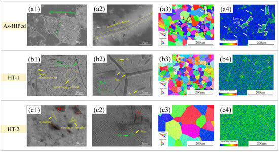
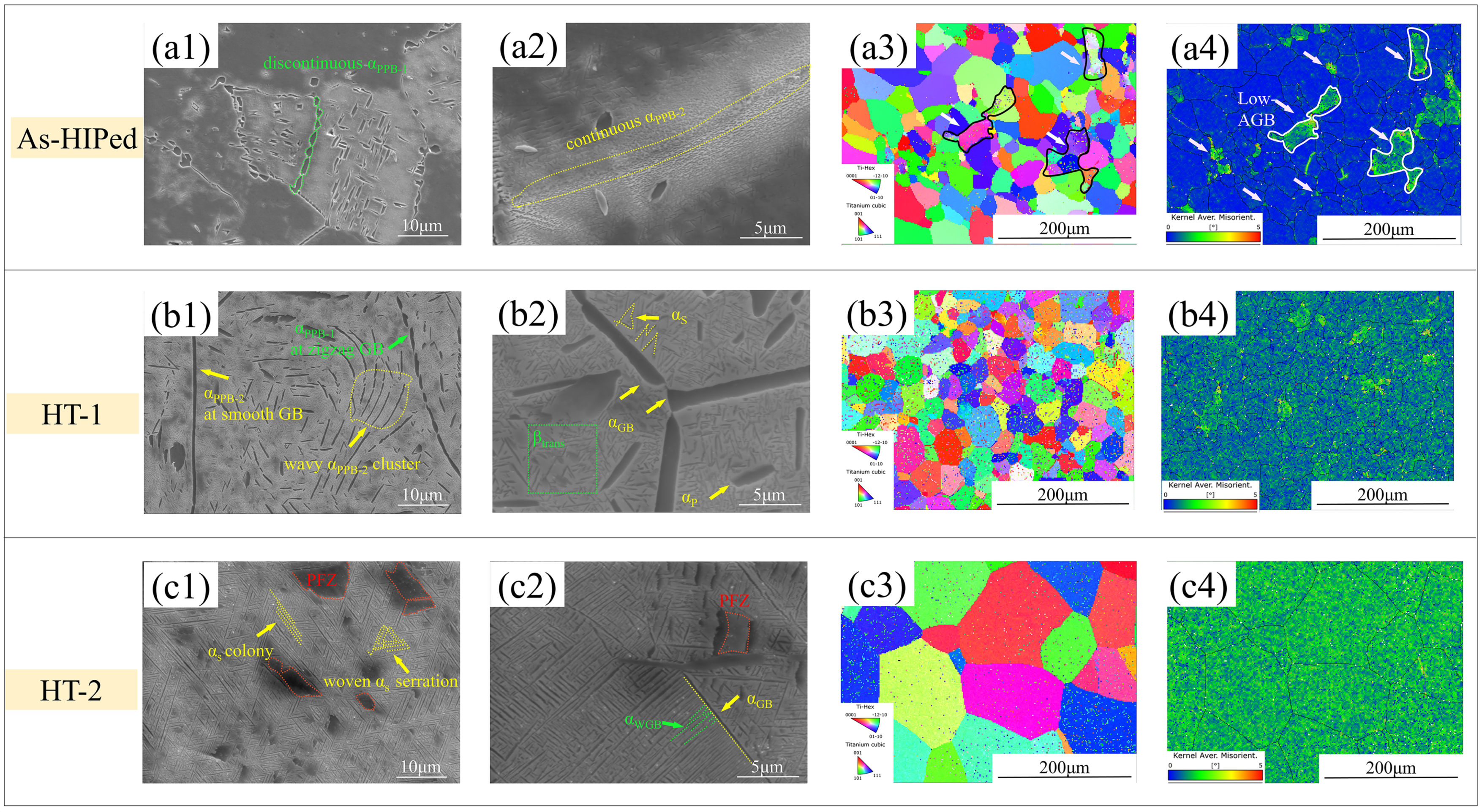
Figure 1 presents secondary electron and EBSD images of the as-HIPed, HT1, and HT2 microstructures. The inhomogeneous βtrans regions are composed of several deformed particles measuring 25~45 μm in length, as seen in Figure 1(a1). Discontinuous quasi-equiaxed αPPB-1 necklaces, approximately 2.5 μm in diameter, are distributed along prior particle boundaries (PPBs). These result from the high tendency for incipient plasticity and dislocation nucleation at the actual Tβ-HIP temperature [41]. The other type of PPB features continuous curved αPPB-2 threads, which evolve from less-deformed PPB surfaces (Figure 1(a2)). These nearly pinch off elemental diffusion and interfacial bonding between powders owing to the insufficient recrystallization driving force [31]. It is widely accepted that dynamic recrystallization (DRX) under high temperature and pressure gives rise to the discontinuous PPB-1 type. The size of αPPB-1 is more pronounced than that of αPPB-2, which is attributed to the greater degree of deformation and localized heat concentration between smaller powders [42].
Figure 1.
Representative SEM, IPF and KAM micrographs of (a1–a4) as-HIPed; (b1–b4) HT-1; (c1–c4) HT-2 specimens.
As shown in Figure 1(b1,b2), the microstructure displays heterogeneous structural characteristics. After the α + β phase-field solution and aging treatment, the sharp-edged lamellar αP, quasi-equiaxed αPPB-1 and curved αPPB-2 within the grains evolve into smooth lamellar αP and wavy αPPB-2 clusters, as well as zigzag (green arrows) and smooth grain boundary (αGB, yellow arrows). Additionally, numerous sub-micron and nano-scale secondary αS laths precipitate from the β matrix.
Figure 1(c1,c2) reveals that the equiaxed αPPB-1 and wavy αPPB-2 clusters are completely eliminated from the matrix after solution treatment in the β phase field. Meanwhile, most of the curved and narrow αPPB-2 threads disappear and a small fraction is transformed into a continuous αGB phase. Arrangements of lamellar, colony-like, and woven serrated αS phases precipitate from the matrix in large amounts. In addition, α-Precipitation-free zones (PFZs indicated by red triangles), defined as the β regions devoid of α precipitates, are also dispersed discretely. Table 1 summarizes the quantitative measurements of various α phase morphologies and crystallographic features for the different treatments.
All IPF maps of β grains are distributed in random crystallographic directions since there is rare aggregation of the same color. The average grain size of HT1 declined a little compared with that of as-HIPed, probably originating from static recrystallization (SRX) at PPBs during heat treatment. The area percentage of the LAGBs zone at small-size PPBs, indicated by white arrows in Figure 1(a3,a4), measured 12.5%, which will facilitate recrystallization. The KAM value in Figure 1(a4) concentrated at PPBs to confirm the preferential accumulation of recrystallization driving force derived from deformed storage energy. Annealing in the α + β phase field cannot wipe out local stress concentration at PPBs or enlarge grain size, as seen in Figure 1(b3,b4). Notably, the HT2 specimen (Figure 1(c3)) presented the largest AGS and highest HAGB fraction. Additionally, the lamellar microstructure (Figure 1(c4)), obtained a uniform distribution of KAM values without noticeable color segregation.
3.2. Effect of Heat-Treatment on Tensile Properties
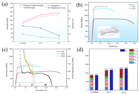
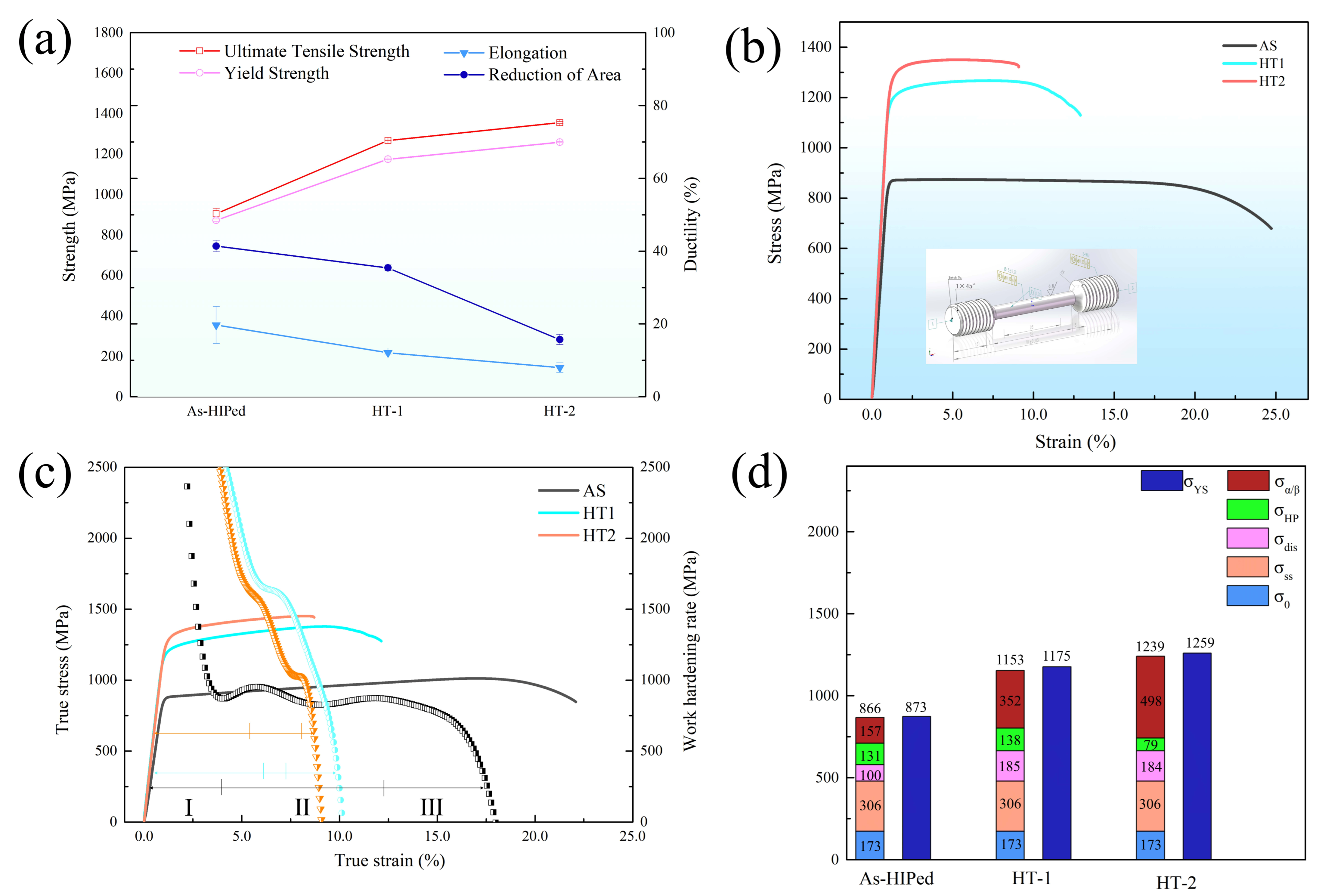
The tensile properties of specimens subjected to various heat treatments are plotted in Figure 2 to assess the mechanical response of the various microstructures. Figure 2a summarizes the ultimate tensile strength (σUTS), yield strength (σYS), total elongation (εt) and reduction in area for each condition. The HT2 specimens exhibit the highest σUTS, reaching 1355 ± 5.3 MPa, accompanied by a satisfactory elongation of 8.0% ± 1.3%. Although the average grain size of the as-HIPed samples is nearly one-third that of the HT2 ones, the as-HIPed condition exhibits the lowest σYS (873 ± 6.2 MPa), suggesting that grain-refinement strengthening plays only a minor role in the yield strength of the Ti55541 alloy [43].
Figure 2.
Tensile properties of the three sets of experimental specimens at ambient temperature: (a) the trends of σUTS, σYS, εt and rupture of area; (b) representative engineering strain–stress curves with an inset of a tensile schematic picture; (c) the true strain–stress curves and work-hardening rate curves corresponding to (b), with the various work-hardening stages labeled as I, II, III; (d) a stacked column diagram of the calculated yield strength σYS and the experimental results.
To further elucidate the tensile deformation behavior, representative engineering stress–strain curves of the three conditions are drawn in Figure 2b. The as-HIPed curve exhibits the lowest σUTS and uniform elongation (εu) of 874 MPa and 4.3% respectively, but the highest total elongation (εt) of 19.7%. After the α + β phase-field solution and aging, the HT1 specimens exhibit a marked increase in σUTS and εu to 1267 MPa and 7.11%, whereas εt plunges to 12.9%. As the solution temperature increased over the Tβ transus, HT2 specimens displayed a decrease in both εt and εu owing to the shortage of deformation coordination from the largest grain size and highest α fraction.
Figure 2c depicts the true stress–strain curves and the corresponding work hardening rate (WHR) curves derived from Figure 2b. Following the classification commonly adopted for titanium alloys [11,44,45], the WHR curves can be divided into three stages (I–III). Stages I and III are characterized by a monotonic and parabolic decrease in WHR, respectively, while stage II exhibits a slight increase with minor fluctuations. According to Considere’s criterion, the onset of necking in the as-HIPed specimen occurs at a relatively early strain, consistent with previous findings on the HIPed Ti5553 alloy [31]. As the true strain increases from approximately 4% to 13%, the work-hardening capacity of the as-HIPed specimen is progressively exhausted until final fracture, without abrupt catastrophic failure. This demonstrates the avoidance of significant PPB debonding or detrimental micro-defect propagation. In contrast to the heat-treated WHR curves, the as-HIPed curve displays two ascending arcs, which likely arise from the non-synchronous deformation of the constituent phases, i.e., the β matrix, βtrans regions and local α phases [46]. The higher initial WHR at the onset of stage II can be attributed to the presence of abundant and heterogeneous α precipitates.
To further evaluate the independent contributions to the yield strength σy, a superposition of strengthening mechanisms can be expressed as Equation (1):
where σ0 represents the inherent critical slip-activation stress of pure Ti (σ0 = 172.5 MPa) [47]; σSS represents the contribution from solid-solution strengthening; σdis represents the contribution from dislocations; σHP represents the contribution from Hall–Petch grain-boundary strengthening; and σα/β represents the contribution from interface barrier strength, which is caused by the modulus mismatch and the dislocation misfit at the α/β interface [48].
For a β-titanium alloy with a multiple composition, solute atoms effectively impede dislocation motion via interactions with lattice defects. The solid-solution strengthening contribution (σSS) can be expressed as Equation (2) [49]:
where Xi is the atomic concentration (at. %) of solute i. And Bi represents the corresponding solid-solution strengthening coefficient, the values of which are listed in Table S1.
The dislocation strengthening contribution (σdis) is estimated using the Taylor hardening model, given by Equation (3) [11]:
where a is the geometrical factor (~0.3), representing the average strength of dislocation junction strengths. M is the Taylor factor, correlated with material texture and the predictive slip system. It should be noted that the parameter M is defined separately as Mα for the α phase and as Mβ for the β phase in the corresponding calculations; b is the magnitude of Burgers vectors; and G is the shear modulus, calculated as Equation (4):
where E is the elastic modulus, ν is Poisson’s ratio (about 0.33 for titanium alloys). The total pristine dislocation density ρ is defined as Equation (5) [47]:
where and are the volume fractions of the β and α phases, respectively. As XRD lacks adequate resolution to quantitatively account for sub-micron and nano-scale α phases, the phase volume fractions reported herein are derived from SEM image analysis using IPP. Considering the step-size limitation of EBSD, the GND densities within fine phases and grains smaller than 2 μm were approximately neglected. This EBSD-based GND estimation is inherently semi-quantitative. Furthermore, absolute GND densities should be treated with caution, while the observed ranking among the three microstructures is robust because the acquisition and processing conditions were identical.
The GND densities in the α and β phases serve as the immobile dislocation densities required to maintain geometric compatibility.
The grain-boundary strengthening contribution (σHP) is evaluated using the Hall–Petch relationship Equation (6) [50]:
The Hall–Petch coefficient (kHP) is given by Equation (7) [50]:
where kTi = 0.75 MPa·m1/2 for pure Ti [43], and Xi is the atomic fraction of alloying element i (at.%). In this study, the calculated kHP is approximately 0.92 MPa·m1/2.
In addition to grain-boundary strengthening, dislocation accumulation at α/β phase interfaces between laths also provides a strengthening effect that cannot be overlooked. The interface strengthening contribution (σα/β) can be expressed as Equation (8) [48]:
where λ is the average distance between neighboring α precipitates (statistically measured from micrographs), and kα/β is the H-P coefficient for the α/β interface strengthening effect, calculated as Equation (9) [48]:
where M is the Taylor factor, b is the magnitude of the Burgers vectors, ω is a constant of 0.84, σIBS is the interface barrier strength (IBS), and μ* is the intrinsic shear modulus of phase on one side of interface.
Following the work of Wang et al. [48] and Guo et al. [51], kα/β is taken as 0.273 MPa·m1/2 for both α and β laths. The physical constants and microstructural parameters used in Equations (1)–(8) are summarized in Table S1.
Figure 2d depicts histograms comparing the estimated and experimental yield strengths, along with the individual contributions of each strengthening mechanism. It is noteworthy that the random distribution of the local α phase in the as-HIPed inhomogeneous microstructure provides the minimum α/β interface strengthening and dislocation strengthening contributions, due to strain softening of the neighboring β matrix. Consequently, solid-solution strengthening (σSS) plays a dominant role in the as-HIPed specimens, accounting for approximately 35.3% of the calculated σYS. The heterogeneous α laths and colonies in the HT1 specimens offered more α/β interface strengthening, with σα/β contributing about 30.5% (HT1) to the yield strength.
In addition, the HT2 hierarchical α laths exhibit the highest α/β interface strengthening contribution (40.2%), supplemented by solute and dislocation hardening. Notably, increasing the solution temperature from the α + β to the β phase fields results in an average grain size approximately three times larger than that of the other conditions, leading to a marked difference in the grain-boundary strengthening contribution.
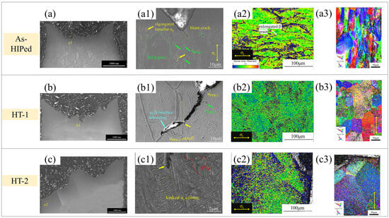
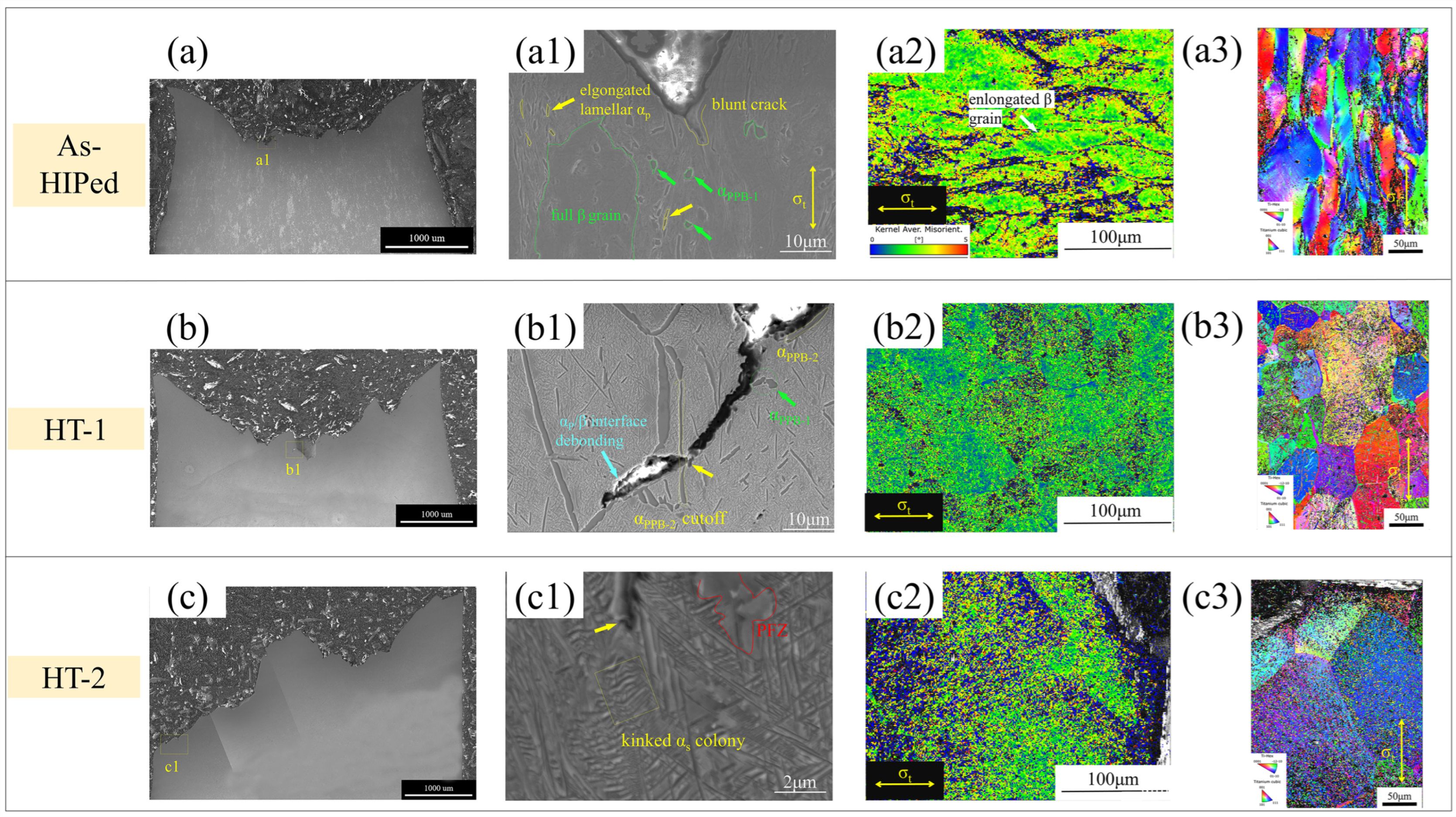
To illuminate the fracture characterization and tensile deformation mechanisms of the various microstructures, cross-sectional profiles revealing crack initiation and propagation are presented in Figure 3. The as-HIPed specimen exhibits the longest and most tortuous macroscopic necking length and crack path, accompanied by micron-scale inhomogeneous deformation (Figure 3a). Figure 3(a1) describes pronounced elongation and distortion of β grains and lamellar αP after tensile strain, while the morphology of quasi-equiaxed αPPB-1 remains largely unchanged near crack tips. In addition, the crack propagation path tends to be blunted and deflected by local αP (yellow arrows), αPPB-1 (green arrows) and βtrans (green polygon)microstructures.
Figure 3.
SEM KAM and IPF mapping of as-HIPed (a–a3), HT1 (b–b3), and HT2 (c–c3) specimens after tensile testing (lateral view).
In the heterogeneous α microstructures of the HT1 specimens (Figure 3(b1)), a limited number of voids tend to form at lamellar αP/β and quasi-equiaxed αPPB-1/β interfaces (blue arrows) because of the disparity in deformation resistance between the α and β phases. In addition, narrow αPPB-2 threads (yellow arrow) are preferentially sheared along the direction of maximum shear stress, while intragranular short, rod-like αP laths strengthen the matrix through their different orientations and increased phase interface density. In Figure 3(c1), the hierarchical microstructure exhibits kinked and bent αS colonies (yellow arrows), resulting from a mixed shear and normal stress state. Notably, fine precipitate-free zones (PFZs, red polygon) are uniformly distributed, which can promote crack deflection through plastic dissipation [18]. The similar color distribution in the IPF maps (Figure 3(c3)) suggests that plastic deformation is insufficient to alter the β-grain orientation, in clear contrast to the more pronounced orientation spread observed in the inhomogeneous as-HIPed and HT1 morphologies (Figure 3(a3,b3)).
To further examine the local misorientation gradient and strain accommodation in the tensile specimens, kernel average misorientation (KAM) from EBSD data are also presented in Figure 3. The KAM map of the as-HIPed tensile samples (Figure 3(a2)) is characterized by a maximum value of 2.37° and a severe distribution. KAM values are primarily accumulated at grain boundaries and local α/βtrans interfaces, where considerable strain concentration readily promotes dislocation pile-ups and subsequent crack initiation. Figure 3(b2,c2) exhibits a relatively uniform color distribution after heat treatment. More often than not, the strain gradient, formed by the plastic incompatibility at the various α/β interfaces, is known to stimulate the generation and accumulation of GNDs [52]. Accordingly, GNDs contribute to back-stress hardening, which underpins the increase in strength [43]. The GND density in the α phase is of the same order of magnitude as that in the β phase (measured in Table S1). KAM decreases, indicating the relaxation of local orientation gradients due to internal stress release, whereas the GND density shows a counterintuitive increase associated with subgrain formation, which preserves the total geometrically required dislocation content [46]. The increase in local GND density can be attributed to the activation of multiple slip systems and the formation of strain gradients, without sufficient energy to significantly alter the grain orientation.
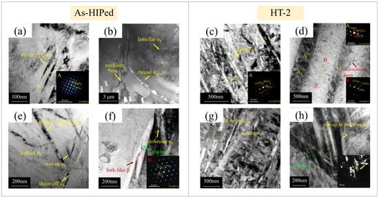
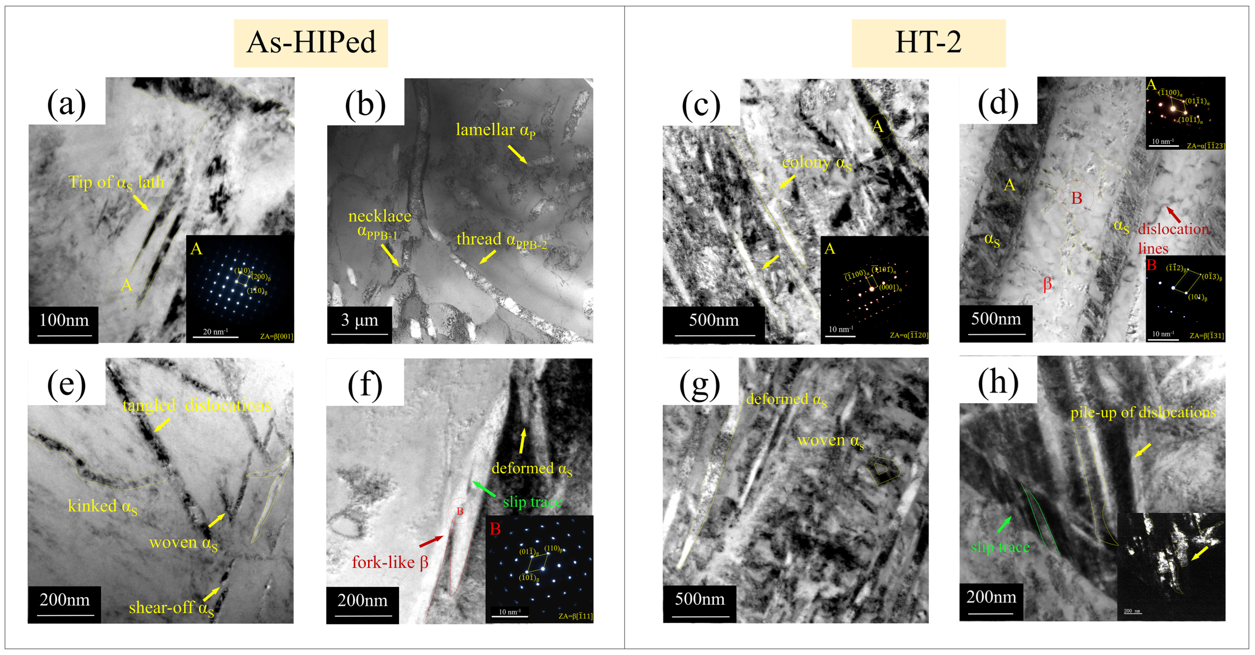
To compare the before-and-after tensile deformation behavior of the as-HIPed and heat-treated microstructures, TEM observations were performed to characterize the local dislocation distribution and phase features (Figure 4). It is well established that dislocation intersection and entanglement preferentially occur in the primary coarse α phase during deformation, owing to its higher elastic modulus and lower strength relative to the β phase [53]. The dislocation density in local αS laths within the β grains, marked by yellow arrows in Figure 4a, is considerably higher than that in the surrounding βtrans microstructure. Figure 4a,b reveals that dislocations preferentially accumulate in the α phase adjacent to grain boundaries or PPB interfaces, which is attributed to the inter-particle pressure generated during powder consolidation.
Figure 4.
TEM images of pristine (a–d) and tensile-deformed (e–h) specimens: (a) the evolution of nano-scale fine αS in local βtrans; (b) TEM microscopy of the αS/βtrans interface corresponding to (a); (c) nano-scale fine and (d) micro-scale coarse αS colonies in HT2 hierarchical specimens; (e,f) deformed α and β phases in as-HIPed inhomogeneous specimens; (g) the dislocation distribution in lamellar and woven αS; and (h) the high density of dislocations in woven αS with a dark-field inset. Note: A and B insets represent the corresponding region of SAED patterns.
The microstructure shown in Figure 4c,d comprises nano-scale fine and micro-scale coarse αS laths with a βtrans matrix. Discernible dislocation entanglement in coarse αS laths is obviously distinguished by dark contrast and is corroborated by corresponding SAED patterns. Figure 4e describes that woven αS laths in as-HIPed specimens accommodate more deformation and provide greater plasticity than fine αS laths crammed with dislocation pile-ups. Both severe deformation and shear cutting were observed exclusively in αS phases. In addition, a deformed fork-like β phase without a high density of dislocations was found at the αS/β interface (Figure 4f), indicating that the neighboring αS had exceeded the limit of strain compatibility. With regard to the hierarchical lamellar microstructure, slip traces and dislocation pile-ups are inclined to occur in the woven and lamellar αS phases, rather than in the intergranular β phases (Figure 4g,h), suggesting that the αS/β interface acts as a stronger barrier to dislocation motion and plays a more crucial role in strengthening. The dark-field image (inset of Figure 4h) verifies that the dislocations are preferentially initiated in coarse αS laths and then develop into slip traces at the αS/β interfaces.
Fractographic observations of the three conditions reveal mixed fracture morphology, comprising both brittle and ductile features. Figure 5a displays a narrow necking region and broad shear lips, along with a minor area of mixed fracture. Furthermore, ductile features, including deep dimples and sharp tearing ridges (Figure 5(a1,a2)), are predominate in the fracture mechanism. Local smooth cleavage facets (indicated by green circles) are also observed, signifying debonding cleavage facets of plastically deformed PPBs (green polygons), consistent with the weak cohesion of narrow and smooth αPPB-2 threads. Heterogeneous HT1 samples (Figure 5(b–b2)) display both brittle and ductile characteristics, with numerous voids, dimples, transgranular cracks (yellow arrow), and cleavage facets. Figure 5(c–c2) shows that brittle features along grain boundaries are the predominant characteristic in the HT2 hierarchical microstructure, like shallow dimples (green arrow), intergranular cleavage facet (yellow arrows), which correlates with its lowest elongation. The coalescence of numerous microvoids also plays a secondary role in plasticity.
Figure 5.
Tensile fractography of annealed samples, containing a variety of fracture modes: (a–c) low-magnification images of macro view; the high-magnification images at the rim (a1–c1) and core (a2–c2), respectively.
3.3. Effect of Heat-Treatment on Impact Properties
Given the potential for catastrophic failure and damage-tolerant considerations in critical components, impact toughness testing is essential for preventing abrupt brittle fracture. The entire impact fracture process, from initial loading to complete failure, lasts only 2–2.25 ms [45].
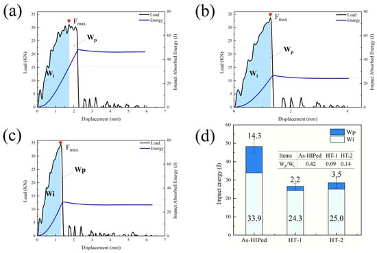
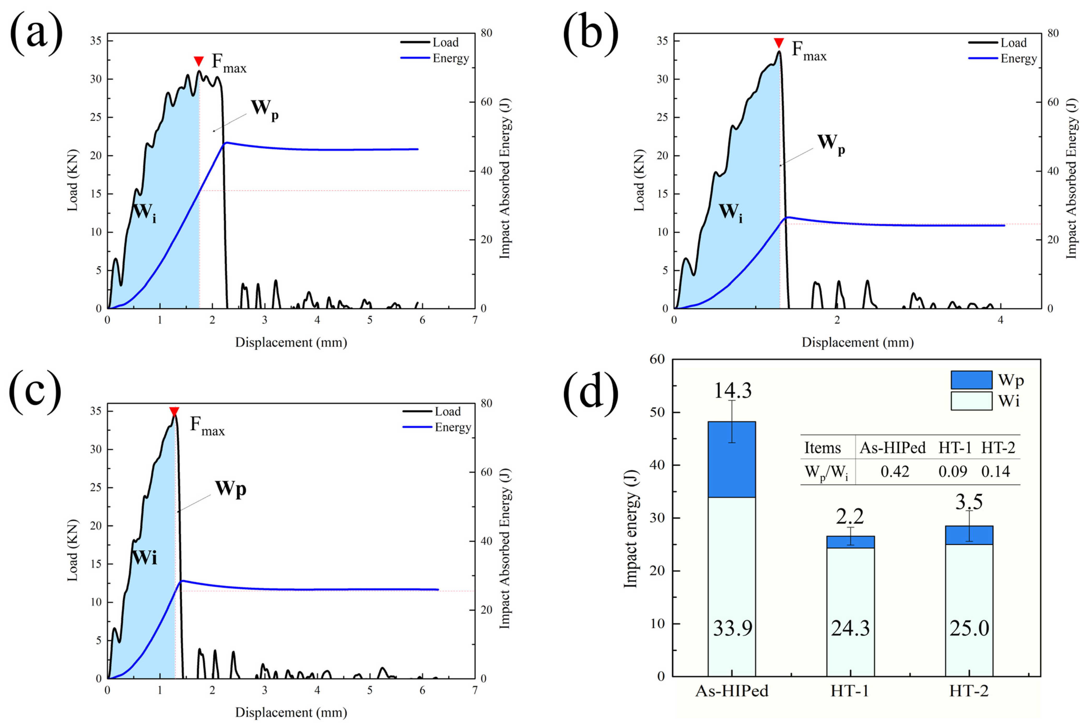
As shown in Figure 6, the load–displacement curves of instrumented impact testing gradually increase with accumulating displacement and then drop sharply to zero after passing the maximum load (Fmax). The area under the load–displacement curves represents the total absorbed impact energy, which is partitioned into two segments at the Fmax point. The left blue region corresponds to the crack initiation energy (Wi), while the right white region corresponds to the crack propagation energy (Wp). Notably, the as-HIPed specimen exhibits the largest Wi and Wp areas despite having the lowest Fmax (Figure 6a), indicating that the impact resistance of the inhomogeneous as-HIPed microstructure is governed primarily by plasticity. In contrast, the HT2 hierarchical microstructure (Figure 6c) displays the highest Fmax, with a higher Wp/Wi than the HT1 specimens. As for conventional Charpy impact toughness, the values for the as-HIPed, HT1 and HT2 are 49.0, 27.8, and 26.0 J/cm2, respectively, which are lower than the instrumented impact toughness owing to the calculation discrepancy.
Figure 6.
Load–displacement and absorbed energy–displacement curves for (a) as-HIPed, (b) HT1, and (c) HT2 specimens; (d) absorbed impact energy partitioned into crack initiation and crack propagation stages. Note: red dotted lines represent the turning points of the load.
The total absorbed impact energies for all conditions are plotted in Figure 6d and the inset table. The Wp/Wi ratio decreases markedly after heat treatment relative to the as-HIPed condition, indicating that post-HIP thermal exposure exerts a more pronounced influence on the extrinsic crack propagation energy than on the intrinsic resistance to crack initiation. Furthermore, the stronger sensitivity of Wp to heat treatment suggests that strategies to improve toughness in this alloy system should focus on enhancing crack propagation resistance—for instance, by increasing the α/β interfacial density—rather than on modifying crack initiation resistance.
To further evaluate the deformation mechanisms during impact toughness testing, cross-sectional microstructures in the vicinity of the crack tips were examined. Figure S3 presents the panoramas of the crack extension paths. The as-HIPed specimen (Figure S3a) exhibits a more tortuous crack path than the solution-treated and aged specimens. No significant undulations are observed in the HT1 crack path morphology (Figure S3b). On the contrary, the HT2 hierarchical microstructure (Figure S3c) shows a nearly straight path with serrated and zigzag grooves, indicating that the lamellar precipitate morphology and large grains provide high resistance to crack extension.
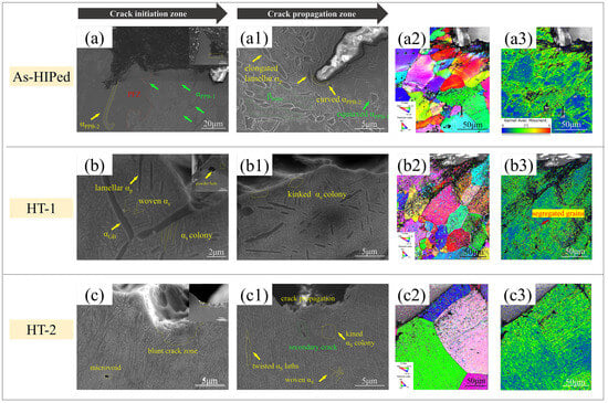
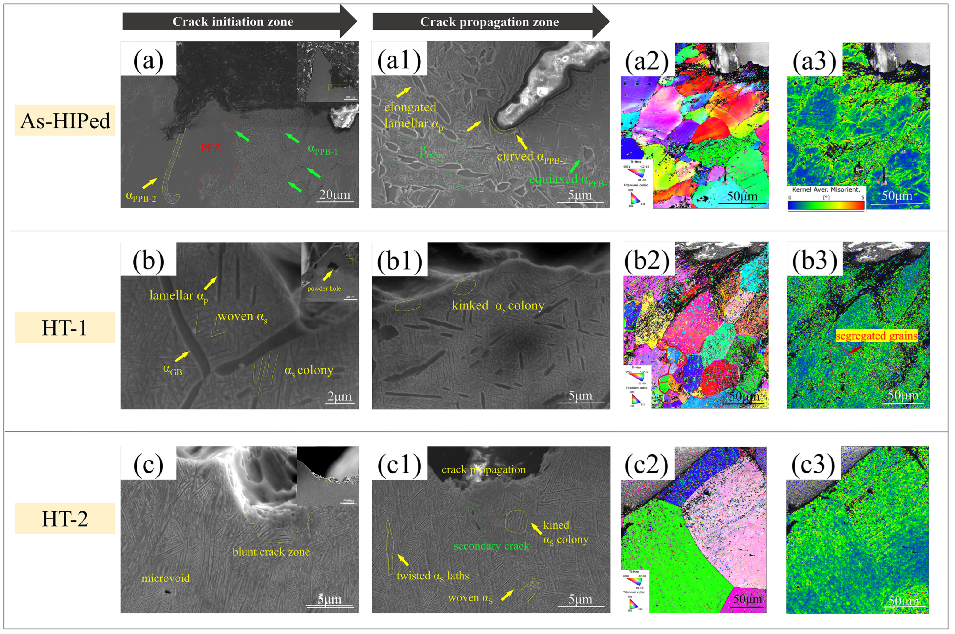
To facilitate comparative analysis of the effect of α phases, PFZs, and βtrans on crack mechanisms, crack initiation and propagation regions were selected for observation in Figure 7. Uniquely, severe grooves and high tearing tips near the U-notch are visible in Figure 7(a–a1) due to the plasticity of full β phase grains and PFZs (red polygons), which lack α precipitates, implying that the crack energy absorption is mainly attributed to β grain orientation differences. As the crack propagates, βtrans (green plygons), narrow αPPB-2 threads, and intragranular αP laths (yellow arrows) are noticeably deformed and kinked along the stress direction to alleviate the tortuosity of crack propagation. Discontinuous quasi-equiaxed αPPB-1 phases (green arrows), however, undergo only minor contortion along the stress direction. This suggests that quasi-equiaxed αPPB-1 phases provide limited impact energy dissipation but significant crack deflection.
Figure 7.
Cross-sectional SEM observations of crack initiation (a–c) and crack propagation (a1–c1) regions in impact specimens. IPF maps (a2–c2) and KAM distributions (a3–c3) derived from EBSD data, show the microstructural characteristics beneath the crack paths.
HT1 specimens display severe plastic deformation features, such as kinked αS colonies and bent αP laths near the crack surface in Figure 7(b,b1). Smooth and blunt crack surfaces are observed in both the initiation and propagation regions of the HT2 specimens, along with slightly kinked αS colonies and twisted αS laths (yellow marks) (Figure 7(c,c1)). It can be established that crack propagation through αS colonies and laths occurs via bypassing or shearing pathways, depending on the angle between the crack and the long axis of the αS laths. When this angle approaches the vertical direction, the αS colonies and laths undergo more extensive deformation and provide stronger interfacial resistance to crack extension, resulting in high strength but low plasticity [10]. Microvoids and secondary cracks away from the path surface are also observed, suggesting the uniform absorption of impact energy and efficient stress transfer through the lamellar microstructure.
The corresponding IPF and KAM maps beneath the crack surface are depicted in Figure 7(a2–c2) and Figure 7(a3–c3) to further elucidate the deformation mechanisms in terms of crystallographic orientation, misorientation, and strain accumulation. As seen in Figure 7(a2,b2), microstructures with low AGS and over 80% HAGB fraction exhibit pronounced IPF color variation, indicating that plastic deformation is sufficient to alter grain orientation during impact testing. Another notable feature is that solution treatment in the α + β field, followed by aging, promotes the precipitation of intragranular coarse αP and woven αS laths with distinct IPF colors. It is well acknowledged that the KAM distribution reflects the intensity and uniformity of plastic deformation. The as-HIPed inhomogeneous microstructure displays localized undeformed (blue) and intergranular deformed (yellow-green) regions after impact testing (Figure 7(a3)). The localization of small grains, originating from the segregation of fine powder particles, provides abundant interfaces that facilitate dislocation accumulation, resulting in higher local KAM values. Among the three impact-tested conditions, the most homogeneous KAM distribution is observed in the HT2 hierarchical microstructure (Figure 7(c3)). The low β phase content tends to reduce the coordinated deformation between the α and β phases, thereby hindering dislocation slip or transmission across semi-coherent α/β interfaces. In addition, KAM values are primarily concentrated at grain boundaries and α/βtrans interfaces near the crack tip.
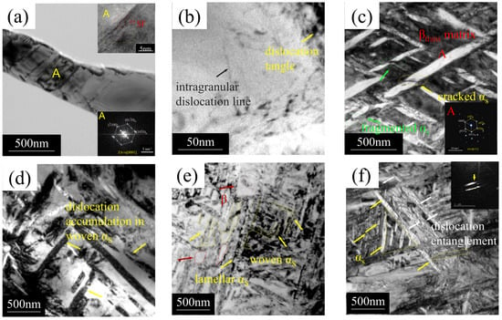
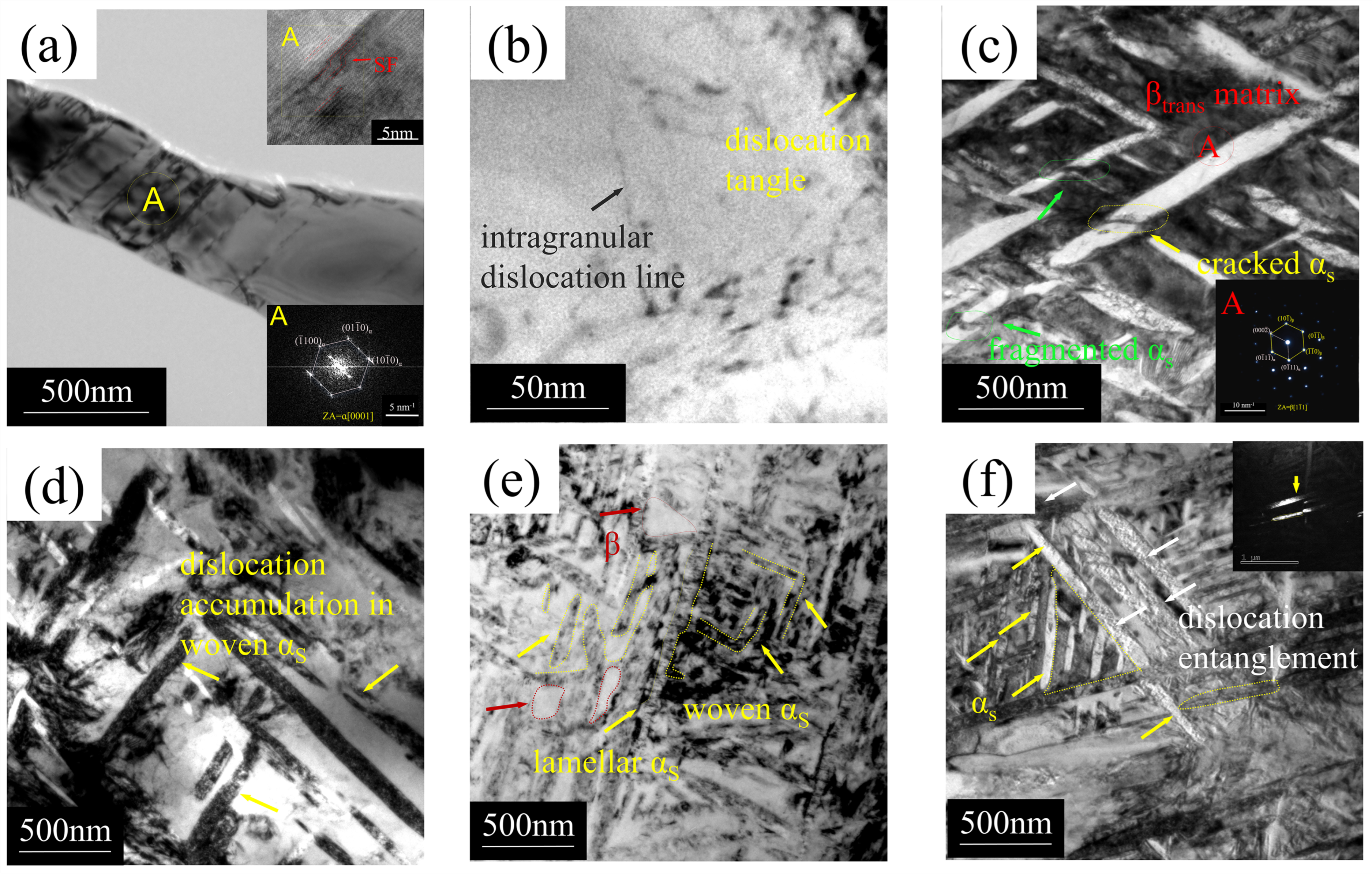
The instantaneous impact toughness of crystalline materials primarily depends on dislocation nucleation and glide under transient stress. To better understand dislocation nucleation, mobility, and segregation, TEM characterization was performed on impact specimens near the crack surface. Figure 8a illustrates a stacking fault in an αP lath, clearly resolved by SAED and HRTEM corresponding to the yellow A circle. This stacking fault is attributed to the low stacking fault energy (SFE) of the Ti55541 alloy and the high strain rate of impact testing. The addition of β stabilizers (Mo, V, and Nb) lowers the SFE for basal and prismatic slip modes, thereby enhancing toughness [7]. Nonetheless, few stacking faults or twins in coarse α laths are observed across the heat-treated specimens, likely because the as-HIPed condition lacks the homogeneous strain compatibility to dissipate deformation energy.
Figure 8.
TEM images of impact specimens under (a,b) as-HIPed, (c,d) HT1, and (e,f) HT2 conditions, including HRTEM, SAED patterns, and dark-field images.
A scattered amount of dislocation lines (black arrow) forms in the β phase without obvious dislocation pile-ups (Figure 8b), whereas the α phase and βtrans matrix generate more dislocations (yellow arrow) caused by stress concentration and lattice mismatch at α/β interfaces. Fine αS laths with little dislocation accumulation are observed to be sheared along the shear stress without pronounced twisting or distortion (Figure 8c,d). Furthermore, high-density dislocations are induced by the numerous semi-coherent α/β interfaces associated with woven αS laths and microscale αS colonies. These dislocations tend to evolve into dislocation tangles through annihilation and rearrangement, accompanied by a reduction in system energy. Figure 8e,f depicts plentiful equilateral triangular αS laths (yellow arrows), indicating that αS laths grow along the Burgers orientation relationship [52]. In this context, the diffusion of α stabilizers at the α/β interface with high strain energy takes precedence over the diffusion within the grain interiors, thereby diminishing the total system energy and providing obstacles to dislocation mobility.
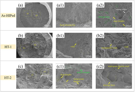
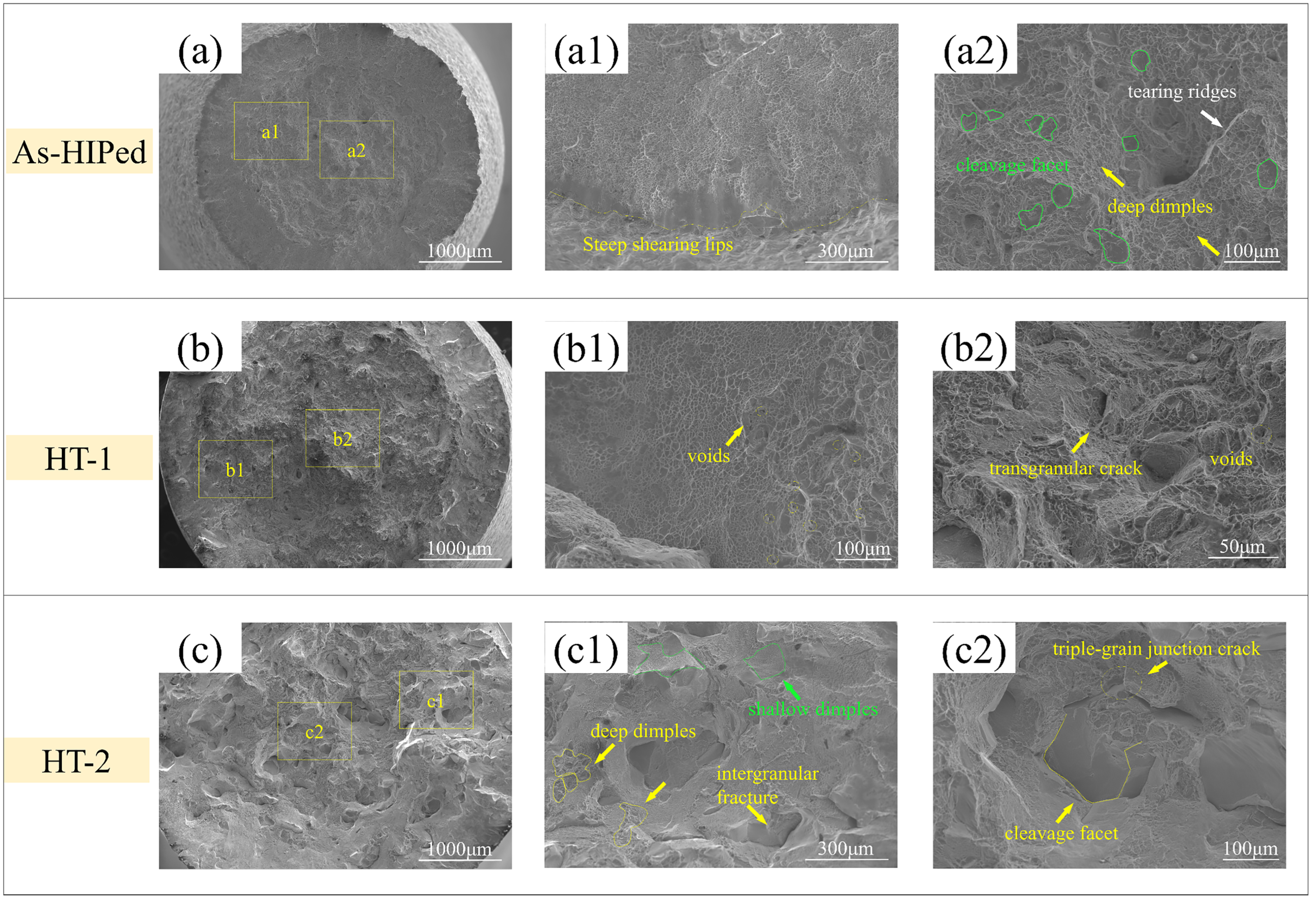
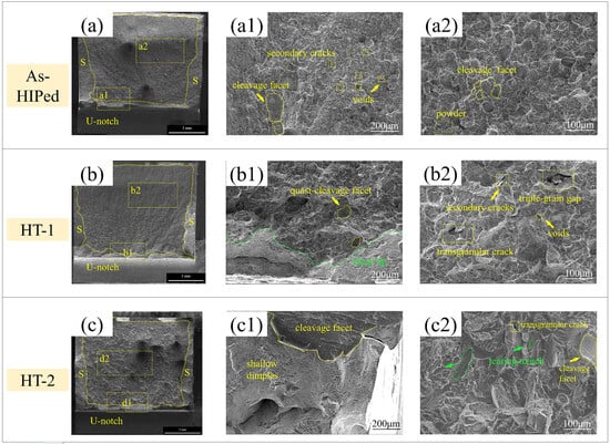
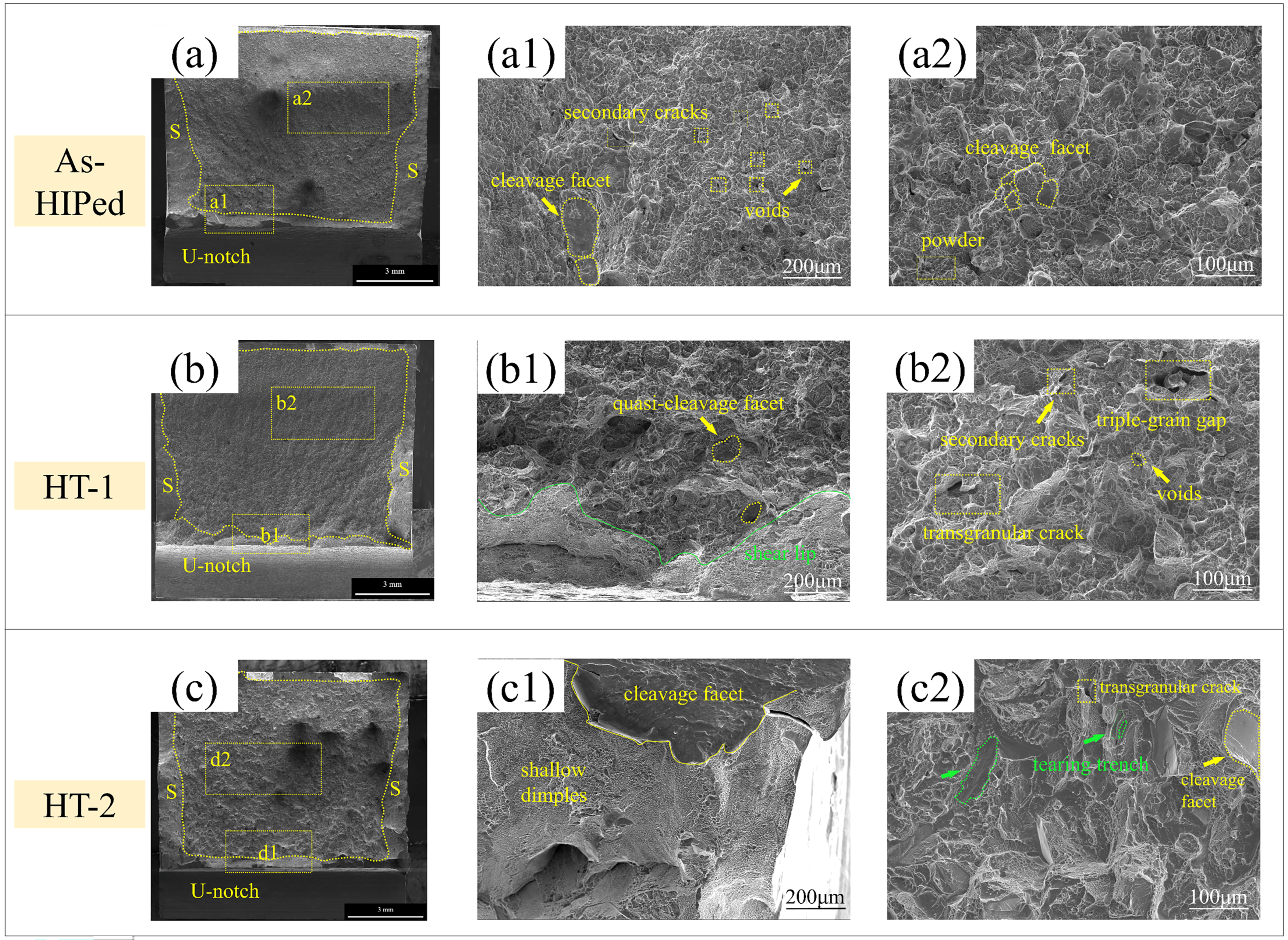
The impact fracture morphology of the three conditions is displayed in Figure 9, generally classified into shear-lip and crack zones. The as-HIPed impact fracture surface in Figure 9(a–a2) exhibits pronounced ductile features, including the largest shear-lip area, extensive deep dimples, and observable voids and secondary cracks. Occasional quasi-cleavage facets and fine powder particles at triple junctions are also observed, which are attributed to insufficient stored deformation energy at large PPB interfaces or hollow triple junctions. After solution treatment in the α + β dual-phase field (Figure 9(b–b2)), shallow dimples and broad transgranular cracks appear, accompanied by a reduction in shear-lip size and depth, indicating decreased impact toughness. For specimens solution-treated in the single β field in Figure 9(c–c2), the fracture surface is characterized by a combination of pronounced tearing trenches (green polygons), distinct cleavage facets, and limited dimples, suggesting that the brittle fracture mode dominates. Overall, the macroscopic impact fractography exhibits a mixed ductile–brittle fracture mode, analogous to that of the tensile specimens.
Figure 9.
Fractography of impact specimens: (a–c) macro fracture surfaces; (a1–c1) crack initiation zones; and (a2–c2) crack propagation zones.
3.4. Analysis of Heat Treatment on Strength–Toughness
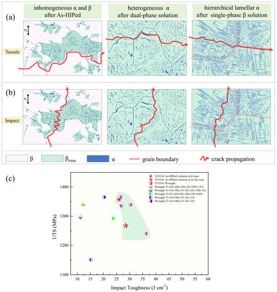
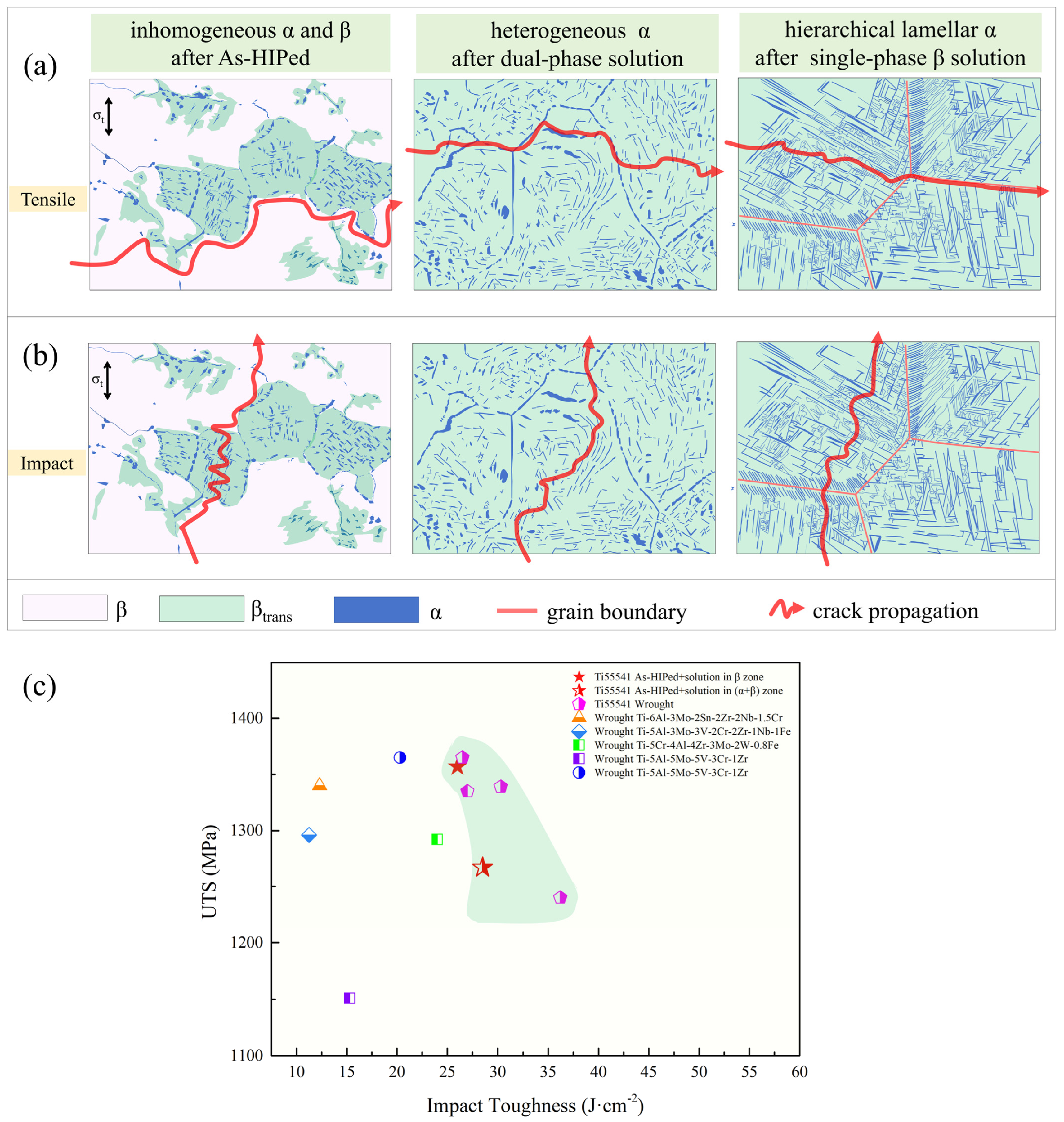
To gain an objective understanding of the influence of various microstructures on toughness and strength under different conditions, it is necessary to discuss the relationship among microstructural characteristics, mechanical performance, and fracture mechanisms. The schematic diagrams of tensile and impact crack characterization are presented in Figure 10a,b.
Figure 10.
Schematic illustration of (a) tensile and (b) impact mechanisms for resistance to crack propagation. (c) Comparison of the ultimate tensile strength (σUTS) versus conventional impact toughness (Ak) between HIP Ti55541 and other wrought high-strength titanium alloys [1,2,4,10,54] with V-notch and [16,19] with U-notch and local green background.
In general, the high β phase fraction is the key factor in both plasticity and toughness, as evident in the as-HIPed specimens. Furthermore, the distribution, size, and morphology of α precipitates exert a significant influence on strength, owing to the limited dislocation slip systems available in the hexagonal close-packed (HCP) α phase. Since different slip systems operate on either side of α/β interfaces, lattice mismatch tends to occur, and microdefects nucleate more readily at α/β threads than at zigzag laths, subsequently propagating along straight α/β interfaces. In contrast to the minimum σUTS and εu in the as-HIPed specimens, εt and Ak remain at their maximum levels. Therefore, the increase in Ak toughness is mainly dependent on total plasticity, with little contribution from elasticity and strength [55]. The high plasticity and toughness in the as-HIPed specimens are mostly attributed to the uniform and random distribution of localized α and βtrans, leading to the alleviation of stress concentration and the improvement of crack initiation resistance. Once cracks overcome critical resistance, the crack pathway bypasses the α + βtrans regions and then extends along the interface between soft and hard areas under quasi-static tensile stress. Under instantaneous impact stress, a notable difference is that localized lamellar αP, αPPB-2, and βtrans undergo more severe twisting and dislocation pile-ups to dissipate impact energy. The formation of the α phase at PPBs arises from the uneven and diverse distribution of the α-stabilizer oxygen and the deformed storage energy.
Stacking faults, which are beneficial to the decomposition of perfect dislocations and the mitigation of stress concentration, were only observed in the as-HIPed impact specimen (Figure 8). Moreover, HIP involves dynamic recrystallization (DRX) processes [35], resulting in the formation of local HAGBs which serve a helpful role in impeding crack propagation and energy depletion around grain and powder boundaries.
HT1 specimens are characterized by the distribution of heterogeneous ɑ precipitates within the βtrans matrix, which corresponds to the WHR curves exhibiting only one climb in stage II (Figure 2c). After solution and aging, the lamellar α becomes coarser with a higher aspect ratio, as solute atoms tend to migrate from lamellar tips and local defect sites to flat interfaces [19]. Consequently, numerous heterogeneous ɑ precipitates are densely distributed in the matrix, resulting in reduced toughness and plasticity. In particular, long αGB phases evolved from intergranular αPPB-2 threads tend to serve as crack initiation sites and rapid propagation pathways, ultimately leading to brittle fractures, as seen in Figure 5 and Figure 9. With regard to intragranular wavy αPPB-2 clusters (Figure 1(b1)), no obvious crack initiation is observed, indicating that the bonding strength of αPPB-2 clusters within the β matrix is relatively stable. Another notable finding is that nano-scale secondary αS phases improve strength via dislocation pile-ups but reduce toughness through brittle shearing fragments (Figure 8c).
The HT2 hierarchical microstructure exhibits the highest strength combined with acceptable toughness. The detrimental PPBs and heterogeneous α phases in the as-HIPed and HT1 samples are nearly eliminated after HT2 heat treatment. In both tensile and impact toughness measurements, the hierarchical microstructure exhibits a mixed fracture mode with a predominantly brittle component. Furthermore, crack nucleation is likely to occur at interfaces among PFZs, single long αS laths, and αGB phases owing to localized strain incompatibility. On the one hand, the coalescence of tearing trenches and microvoids plays a paramount role in enhancing impact crack propagation. On the other hand, twisted single αS laths, kinked αS colonies, distorted αWGB arrays, and localized fine PFZs consume the majority of crack energy [47]. In addition, the multiplication, mobility and entanglement of dislocations at coherent interfaces among multi-scale woven αS and the matrix contribute to toughness to some extent. The over 98% HAGB fraction tends to pin dislocations at low-energy surfaces and promote crack deflection along grain boundaries, further supporting the evidence for intergranular fracture and brittle dominance.
The comparison of various β-titanium alloys in terms of ultimate tensile strength and impact toughness is presented in Figure 10c. In the present work, the hierarchical microstructure, characterized by a large average grain size and low LAGB fraction, exhibits a prominent balance, alleviating the inherent trade-off among strength, plasticity and toughness. Remarkably, the Ti55541 specimens subjected to as-HIPed plus β phase solution and α + β aging heat treatments show a slight advantage over their wrought counterparts in the combination of strength and toughness. Our findings suggest that HIP combined with appropriate heat treatment, as a near-net-shaping technique, can achieve mechanical performance that is not inferior to forging, which relies on stress-induced strengthening and toughness. Given the microstructural characterization of the present specimens, further investigation of fracture toughness and notch high-cycle fatigue strength for HIP + heat-treated material is warranted in order to establish a comprehensive mechanical understanding of this multi-element β-titanium alloy for cost-effective engineering applications.
4. Conclusions
In the present work, metastable β Ti55541 compacts with three tailored microstructures were designed and fabricated via hot isostatic pressing (HIP) followed by post-HIP heat treatments. The main conclusions can be drawn as follows:
- The as-HIPed morphology is characterized by random inhomogeneity in three dimensions with a phase constitution comprising localized lamellar αP, quasi-equiaxed αPPB-1, thread-like αPPB-2, βtrans and β matrix. For solution treatment in the α + β dual-phase field and subsequent aging, the resulting heterogeneous microstructure was composed of rod-like αP, fine secondary αS and wavy αPPB-2 clusters. After solution treatment in the β phase field followed by aging, hierarchical α laths, ranging from nano-scale to micro-scale in length, predominantly occupy the matrix.
- A mixed fracture mode comprising both ductile and brittle features is observed across all three microstructural types during tensile and impact testing. To be specific, the inhomogeneous and hierarchical specimens are dominated by ductile and brittle fracture modes, respectively, while the heterogeneous samples exhibit an intermediate behavior. Overall, the interfaces between the β matrix and αPPB-2 threads and αGB phases act as preferential sites for crack initiation and are detrimental to both strength and toughness.
- The favorable combination of strength, plasticity and toughness is achieved in the hierarchical αS lath microstructure, with values of approximately 1355 MPa for ultimate tensile strength, 8.0% for total elongation, and 26.0 J·cm−2 for impact toughness. The optimal tensile plasticity and impact toughness are obtained in the as-HIPed inhomogeneous microstructure, with values of approximately 19.7% and 49.0 J·cm−2 respectively. The above findings demonstrate that HIP, as a near-net-shaping technique, holds promising potential for fabricating metastable β-titanium components with desirable mechanical performance for aerospace applications.
Supplementary Materials
The following supporting information can be downloaded at: https://www.mdpi.com/article/10.3390/met16111275/s1, Table S1: Physical constants and microstructural parameters used in yield strength calculations; Figure S1: SS-PREP Ti55541 powder micrographs; Figure S2: Three-dimensional OM showing the microstructure of Ti55541 compacts; Figure S3: Cross-sectional SEM observations of crack initiation and crack propagation regions in impact specimens. IPF maps and KAM distributions derived from EBSD data show the microstructural characteristics beneath the crack paths; Figure S4: The drawing of cylinder envelope with dimensions; Figure S5: Figures and drawings of the specimens.
Author Contributions
Conceptualization, X.Z. and W.C.; methodology, X.Z., L.D. and S.L.; validation, S.L.; formal analysis, X.Z.; investigation, X.Z., L.D. and Y.L.; resources, Y.L.; data curation, X.Z. and L.D.; writing—original draft preparation, X.Z.; writing—review and editing, X.Z., L.D. and Y.L.; visualization, X.Z. and L.D.; funding acquisition, W.C. All authors have read and agreed to the published version of the manuscript.
Funding
This work was funded by the National Natural Science Foundation of China (Grant Nos. 52431001, 52271113, 52431006 and 52441407) and Technology Innovation Leading Program of Shaanxi (Program No. 2025CG-SSPY-023).
Data Availability Statement
The original contributions presented in this study are included in the article. Further inquiries can be directed to the corresponding author.
Conflicts of Interest
Authors Xiaohao Zhao, Liyang Dong, Yi Liu, and Shaoqiang Li were employed by the company “Sino-Euro Materials Technologies of Xi’an Co., Ltd.”. The remaining authors declare that the research was conducted in the absence of any commercial or financial relationships that could be construed as a potential conflict of interest.
Abbreviations
The following abbreviations are used in this manuscript:
| PPB | Prior Particle Boundary |
| DRX | dynamic recrystallization |
| PFZ | α-Precipitation free zones (PFZs) |
References
- Wang, J.; Zhao, Y.; Zhao, Q.; Lei, C.; Zhou, W.; Zeng, W. Comparison on impact toughness of high-strength metastable β titanium alloy with bimodal and lamellar microstructures. Metals 2022, 12, 271. [Google Scholar] [CrossRef] [Scilit]
- Huang, C.; Wang, F.; Wen, X.; Wan, M.; Lei, M.; Ye, J.; Zeng, W. Tensile performance and impact toughness of Ti-55531 alloy with multilevel lamellar microstructure. J. Mater. Sci. 2021, 56, 8848–8870. [Google Scholar] [CrossRef] [Scilit]
- Yao, K.; Min, X.; Emura, S.; Meng, F.; Ji, X.; Tsuchiya, K. Enhancement of impact toughness of β-type Ti–Mo alloy by {332}<113> twinning. J. Mater. Sci. 2019, 54, 11279–11291. [Google Scholar] [CrossRef] [Scilit]
- Li, Z.; Wu, G.; Huang, Z. Relationships between microstructure and mechanical properties of Ti-5Al-5Mo-5V-3Cr-1Zr alloy. Mater. Res. Express 2018, 5, 036518. [Google Scholar] [CrossRef] [Scilit]
- Kang, L.; Yang, C. A review on high-strength titanium alloys: Microstructure, strengthening, and properties. Adv. Eng. Mater. 2019, 21, 1801359. [Google Scholar] [CrossRef] [Scilit]
- Ballor, J.; Li, T.; Prima, F.; Boehlert, C.J.; Devaraj, A. A review of the metastable omega phase in beta titanium alloys: The phase transformation mechanisms and its effect on mechanical properties. Int. Mater. Rev. 2023, 68, 26–45. [Google Scholar] [CrossRef] [Scilit]
- Huang, S.; Zhao, Q.; Zhao, Y.; Lin, C.; Wu, C.; Jia, W.; Mao, C.; Ji, V. Toughening effects of Mo and Nb addition on impact toughness and crack resistance of titanium alloys. J. Mater. Sci. Technol. 2021, 79, 147–164. [Google Scholar] [CrossRef] [Scilit]
- Huang, S.; Zhao, Q.; Yang, Z.; Lin, C.; Zhao, Y.; Yu, J. Strengthening effects of Al element on strength and impact toughness in titanium alloy. J. Mater. Res. Technol. 2023, 26, 504–516. [Google Scholar] [CrossRef] [Scilit]
- Li, K.; Chen, W.; Yu, G.; Zhang, J.; Sun, J. A novel deformation mechanism in Ti-V binary metastable β-Ti alloys: Deformation kinking promoted by dislocation accumulation. J. Alloys Compd. 2021, 875, 159982. [Google Scholar] [CrossRef] [Scilit]
- Wu, C.; Zhao, Y.; Huang, S.; Lei, L.; Zhao, Q.; Sun, Q.; Zhou, L. Microstructure tailoring and impact toughness of a newly developed high strength Ti-5Al-3Mo-3V-2Cr-2Zr-1Nb-1Fe alloy. Mater. Charact. 2021, 175, 111103. [Google Scholar] [CrossRef] [Scilit]
- Li, K.; Chen, W.; Zhang, J.; Xin, S.; Sun, J. Making titanium alloys ultrahigh strength and toughness synergy through deformation kinks-mediated hierarchical α-precipitation. J. Mater. Sci. Technol. 2025, 207, 142–159. [Google Scholar] [CrossRef] [Scilit]
- Cotton, J.D.; Briggs, R.D.; Boyer, R.R.; Tamirisakandala, S.; Russo, P.; Shchetnikov, N.; Fanning, J.C. State of the art in beta titanium alloys for airframe applications. JOM 2015, 67, 1281–1303. [Google Scholar] [CrossRef] [Scilit]
- Guo, J.; Zhao, Y.; Zhu, M.; Yang, H.; Song, Y.; Wang, G.; Hao, F.; Liu, X.; Kou, H. Kink bands-mediated ultrahigh plasticity and sustained work hardening in a metastable β titanium alloy. Mater. Sci. Eng. A 2025, 943, 148811. [Google Scholar] [CrossRef] [Scilit]
- Wang, T.; Feng, Y.; Liu, X.; Wang, K.; Li, S.; Zhao, F. Phase Composition Effects on Dynamic Behavior and Strain Rate Sensitivity in Metastable β-Ti Alloys. Materials 2022, 15, 4068. [Google Scholar] [CrossRef] [Scilit] [PubMed]
- Wang, T.; Liu, X.; Feng, Y.; Wang, K.; Sun, S.; Yang, D.; Sun, F. Effect of α Phase on Dynamic Mechanical Properties and Failure of Ti-4Al-5Mo-5V-5Cr-1Nb Alloy after Two-Stage Aging. Metals 2022, 12, 1721. [Google Scholar] [CrossRef] [Scilit]
- Fu, Q.; Xiang, W.; Yuan, W. Effect of deformation and heat treatment parameters on the microstructure and properties of forged TB18 titanium alloy. J. Mater. Sci. 2024, 59, 6986–7008. [Google Scholar] [CrossRef] [Scilit]
- Fu, Q.; Feng, J.; Xiang, W.; Yuan, W. Microstructure Characteristic and Texture Evolution of TB18 Titanium Alloy during Hot Compression in the β Phase Zone. Mater. Trans. 2022, 63, 1416–1424. [Google Scholar] [CrossRef] [Scilit]
- Zhang, F.; Feng, J.; Xiang, W.; Fu, Q.; Yuan, W. Enhanced mechanical properties in metastable β titanium alloy via ω-assisted nucleation. Mater. Sci. Eng. A 2022, 858, 144082. [Google Scholar] [CrossRef] [Scilit]
- Xiang, W.; Yuan, W.; Deng, H.; Luo, H.; Chen, L.; Yin, W. Effect of Aging Temperature on the Microstructure and Mechanical Properties of a Novel β Titanium Alloy. Materials 2023, 16, 7393. [Google Scholar] [CrossRef] [Scilit] [PubMed]
- Yang, J.; Tang, H.; Zhang, Y.; Zhang, Y.; Zhu, Y.; Liu, B.; Cui, Z. Abnormal aging behaviors induced by high-density dislocations for an ultra-high-strength titanium alloy prepared by laser-directed energy deposition. Addit. Manuf. 2024, 95, 104559. [Google Scholar] [CrossRef] [Scilit]
- Chen, L.; Wang, C.; Yin, J.; Zhang, N.; Ye, T.; Guan, T.; Zhao, F.; Kou, H.; Deng, Q. Stable strain hardening behavior of Ti-4Al-5Mo-5V-5Cr-1Nb alloy during plastic deformation. Mater. Today Commun. 2023, 36, 106836. [Google Scholar] [CrossRef] [Scilit]
- Xiang, W.; Li, Q.; Zhang, F.; Fan, Y.; Yuan, W. Microstructure Evolution of TB18 Alloy after Thermal Treatment and the Effect of Recrystallization Texture on Mechanical Properties. Materials 2024, 17, 2828. [Google Scholar] [CrossRef] [Scilit] [PubMed]
- Liu, T.; Liu, X.; Pan, X.; Zhou, W.; Chen, X.; Qiao, Z.; Song, S.; Zhao, H.; Xin, S. High-cycle fatigue crack initiation behavior in TB18 titanium alloy with lamellar microstructure. Mater. Sci. Eng. A 2026, 959, 150081. [Google Scholar] [CrossRef] [Scilit]
- Zheng, Z.; Zhao, D.; Li, K.; Chen, W.; Zhang, J.; Liu, X.; Xin, S.; Sun, J. Trifunctionally strengthening, ductilizing and toughening of TB18 metastable β-titanium alloy through heterogeneous α precipitation. J. Mater. Res. Technol. 2026, 42, 1707–1721. [Google Scholar] [CrossRef] [Scilit]
- Anwar, J.; Bassini, E.; Fino, P.; Lombardi, M.; Bondioli, F.; Aristizabal, M.; Iturriza, I.Z.; Biamino, S.; Ugues, D. A review on near net shape hot isostatic pressing of metallic materials: For industrial applications. J. Mater. Res. Technol. 2026, 42, 3663–3684. [Google Scholar] [CrossRef] [Scilit]
- Guo, R.; Xu, L.; Wu, J.; Yang, R.; Zong, B.Y. Microstructural evolution and mechanical properties of powder metallurgy Ti–6Al–4V alloy based on heat response. Mater. Sci. Eng. A 2015, 639, 327–334. [Google Scholar] [CrossRef] [Scilit]
- Guo, R.; Wang, N.; Cheng, M. Hot Deformation Behavior of a Hot-Isostatically Pressed Ti-6Al-4V Alloy from Recycled Powder. Materials 2024, 17, 990. [Google Scholar] [CrossRef] [Scilit] [PubMed]
- Huo, Y.; Lu, Z.; Cheng, M.; Fan, J.; Qiao, J.; Xu, L.; Guo, R.; Yang, R.; Liaw, P.K. Understanding the dwell-fatigue-damage mechanism of powder metallurgy Ti-6Al-4V alloys fabricated by hot isostatic pressing. Mater. Sci. Eng. A 2023, 883, 145503. [Google Scholar] [CrossRef] [Scilit]
- Zhang, K.; Mei, J.; Wain, N.; Wu, X. Effect of hot-isostatic-pressing parameters on the microstructure and properties of powder Ti-6Al-4V hot-isostatically-pressed samples. Metall. Mater. Trans. A 2010, 41, 1033–1045. [Google Scholar] [CrossRef] [Scilit]
- Cao, L.; Wu, X.; Zhu, S.; Mei, J.; Wu, X.; Bettles, C. The effect of HIPping pressure on phase transformations in Ti–5Al–5Mo–5V–3Cr. Mater. Sci. Eng. A 2014, 598, 207–216. [Google Scholar] [CrossRef] [Scilit]
- Perevoshchikova, N.; Hutchinson, C.R.; Wu, X. The design of hot-isostatic pressing schemes for Ti–5Al–5Mo–5V–3Cr (Ti-5553). Mater. Sci. Eng. A 2016, 657, 371–382. [Google Scholar] [CrossRef] [Scilit]
- Dekhtyar, A.; Bondarchuk, V.; Nevdacha, V.; Kotko, A.; Skoryk, M. Effect of microstructure on porosity healing mechanism of powder near β-titanium alloys under hot isostatic pressing in α+ β-region: Ti-5Al-5 V-5Mo-3Cr. Mater. Charact. 2023, 200, 112846. [Google Scholar] [CrossRef] [Scilit]
- Ding, R.; Chu, M.; Zhang, S. A study of microstructure and mechanical property of a burn-resistant Ti alloy fabricated by HIPping. Mater. Charact. 2020, 163, 110280. [Google Scholar] [CrossRef] [Scilit]
- Chen, G.; Zhao, S.; Tan, P.; Wang, J.; Xiang, C.; Tang, H. A comparative study of Ti-6Al-4V powders for additive manufacturing by gas atomization, plasma rotating electrode process and plasma atomization. Powder Technol. 2018, 333, 38–46. [Google Scholar] [CrossRef] [Scilit]
- Cai, C.; Gao, X.; Teng, Q.; Kiran, R.; Liu, J.; Wei, Q.; Shi, Y. Hot isostatic pressing of a near α-Ti alloy: Temperature optimization, microstructural evolution and mechanical performance evaluation. Mater. Sci. Eng. A 2021, 802, 140426. [Google Scholar] [CrossRef] [Scilit]
- Abdullah, E.C.; Geldart, D. The use of bulk density measurements as flowability indicators. Powder Technol. 1999, 102, 151–165. [Google Scholar] [CrossRef] [Scilit]
- Ni, R.; Zhang, P.; Che, L.; Lv, Z.; Chen, S.; Zhang, L.; Li, X. Effect of Powder Production Methods on Microstructure and Mechanical Properties of Hot Isostatically Pressed TA15 Alloy. J. Phys. Conf. Ser. 2025, 2956, 012035. [Google Scholar] [CrossRef] [Scilit]
- Guo, R.; Xu, L.; Chen, Z.; Wang, Q.; Zong, B.Y.; Yang, R. Effect of powder surface state on microstructure and tensile properties of a novel near α-Ti alloy using hot isostatic pressing. Mater. Sci. Eng. A 2017, 706, 57–63. [Google Scholar] [CrossRef] [Scilit]
- Zhu, L.; Pan, Y.; Liu, Y.; Sun, Z.; Wang, X.; Nan, H.; Mughal, M.-A.; Lu, D.; Lu, X. Effects of microstructure characteristics on the tensile properties and fracture toughness of TA15 alloy fabricated by hot isostatic pressing. Int. J. Miner. Metall. Mater. 2023, 30, 697–706. [Google Scholar] [CrossRef] [Scilit]
- Cai, C.; Song, B.; Xue, P.; Wei, Q.; Yan, C.; Shi, Y. A novel near α-Ti alloy prepared by hot isostatic pressing: Microstructure evolution mechanism and high temperature tensile properties. Mater. Des. 2016, 106, 371–379. [Google Scholar] [CrossRef] [Scilit]
- Liu, Z.; Yang, J.; Peng, B.; Ye, J.; Liu, Y.; Du, Z.; Chen, R. Challenges related to elevated temperature during creep in a PM-HIP Ti-6Al-4 V alloy: The role of <a> dislocations and pyramidal <c+a> dislocations. J. Mater. Sci. Technol. 2025, 213, 252–267. [Google Scholar] [CrossRef] [Scilit]
- Wang, Y.; Xue, X.; Kou, H.; Chang, J.; Yin, Z.; Li, J. Improvement of microstructure homogenous and tensile properties of powder hot isostatic pressed TA15 titanium alloy via heat treatment. Mater. Lett. 2022, 311, 131585. [Google Scholar] [CrossRef] [Scilit]
- Zhang, C.; Bao, X.; Zhang, D.; Chen, W.; Zhang, J.; Kuang, J.; Liu, G.; Sun, J. Achieving superior strength-ductility balance in a novel heterostructured strong metastable β-Ti alloy. Int. J. Plast. 2021, 147, 103126. [Google Scholar] [CrossRef] [Scilit]
- Chen, W.; Li, K.; Yu, G.; Ren, J.; Zha, Y.; Sun, J. Deformation twinning-induced single-variant ω-plates in metastable β-Ti alloys containing athermal ω-precipitates. J. Mater. Sci. 2021, 56, 7710–7726. [Google Scholar] [CrossRef] [Scilit]
- Gao, S.; Pan, K.; Chen, D.; Wang, B.; Wu, S.; Luo, X.; Sun, M.; Zhao, C.; Li, N. Mechanism of oxygen content on impact toughness of α+ β powder metallurgy titanium alloy. J. Mater. Res. Technol. 2024, 33, 318–334. [Google Scholar] [CrossRef] [Scilit]
- Mao, Y.; Zhao, Q.; Zhang, R.; Guo, P.; Chen, Y.; Zhao, Y. Trifunctional local-range order oxygen structure enhanced strength-ductility and fatigue resistance in large-scale metastable titanium alloy. Nat. Commun. 2025, 16, 7168. [Google Scholar] [CrossRef] [Scilit] [PubMed]
- Li, D.; Huang, H.; Chen, C.; Liu, S.; Liu, X.; Zhang, X.; Zhou, K. Additive manufacturing of high strength near β titanium alloy Ti-55511 by engineering nanoscale secondary α laths via in-situ heat treatment. Mater. Sci. Eng. A 2021, 814, 141245. [Google Scholar] [CrossRef] [Scilit]
- Wang, F.; Luo, X.-M.; Lei, L.-M.; Fu, X.; Zhang, B.; Zhang, G.-P. Theoretical evaluation of strengthening ability of phase interfaces in lamellar Ti alloys. Adv. Eng. Mater. 2022, 24, 2101570. [Google Scholar] [CrossRef] [Scilit]
- Zhao, G.-H.; Liang, X.; Kim, B.; Rivera-Díaz-del-Castillo, P.E. Modelling strengthening mechanisms in beta-type Ti alloys. Mater. Sci. Eng. A 2019, 756, 156–160. [Google Scholar] [CrossRef] [Scilit]
- Wu, D.; Zhang, J.; Huang, J.; Bei, H.; Nieh, T.-G. Grain-boundary strengthening in nanocrystalline chromium and the Hall–Petch coefficient of body-centered cubic metals. Scr. Mater. 2013, 68, 118–121. [Google Scholar] [CrossRef] [Scilit]
- Guo, M.; Huang, T.; Luo, T.; Huang, X.; Li, J.; Lai, M. Manipulation of the α-phase precipitation behavior through dual-aging treatment and its correlation with mechanical properties in a metastable β titanium alloy. J. Alloys Compd. 2024, 1005, 175891. [Google Scholar] [CrossRef] [Scilit]
- Cao, Y.; Li, N.; Luo, Y.; Tang, H.; Xie, Q.; Fu, A. A novel ultra-high strength titanium alloy via hierarchical α/α′ precipitation strengthening. Mater. Sci. Eng. A 2022, 840, 142878. [Google Scholar] [CrossRef] [Scilit]
- Wang, K.; Li, H.; Zhou, Y.; Wang, J.; Xin, R.; Liu, Q. Dislocation slip and crack nucleation mechanism in dual-phase microstructure of titanium alloys: A review. Acta Metall. Sin. 2023, 36, 353–365. [Google Scholar] [CrossRef] [Scilit]
- Lei, L.; Zhao, Q.; Zhao, Y.; Huang, S.; Wu, C.; Jia, W.; Zeng, W. Study on the intrinsic factors determining impact toughness of TC21 alloy. Mater. Charact. 2021, 177, 111164. [Google Scholar] [CrossRef] [Scilit]
- Sun, Y.; Gong, H.; Ying, J.; Xu, S.; Yang, L.; Zhang, J.; Fan, Q. Quantitative relationship between impact toughness and quasi-static tensile properties of Ti-652 titanium alloy. J. Alloys Compd. 2024, 971, 172678. [Google Scholar] [CrossRef] [Scilit]

Disclaimer/Publisher’s Note: The statements, opinions and data contained in all publications are solely those of the individual author(s) and contributor(s) and not of MDPI and/or the editor(s). MDPI and/or the editor(s) disclaim responsibility for any injury to people or property resulting from any ideas, methods, instructions or products referred to in the content. |
© 2026 by the authors. Licensee MDPI, Basel, Switzerland. This article is an open access article distributed under the terms and conditions of the Creative Commons Attribution (CC BY) license.