


Abstract
Si and Al modify the microstructure and properties of carbide-free bainitic steels, but the effects of their relative proportions at a fixed nominal combined content require further clarification. Three steels containing a nominal total of 1.8 wt.% Si + Al were austenitized at 950 °C for 300 s and isothermally held at 350 °C for 1000 s. Dilatometry, microstructural characterization, X-ray diffraction, and tensile testing were used to investigate transformation behavior, microstructure, retained austenite (RA) stability, and mechanical properties. With increasing Al/Si ratio, the mean bainitic ferrite lath thickness decreased from 206.2 nm in A0 to 196.1 nm in A08 and 155.2 nm in A10. A10 exhibited a higher relative transformation rate during the early and intermediate stages. The estimated RA carbon content and proportion of film-like RA increased, while the cumulative fraction of RA transformed during tensile testing to fracture decreased from 65.3% to 29.2%. A08 sustained a high strain-hardening rate over a broad strain range, achieving an ultimate tensile strength of 1016.3 ± 15 MPa and an elongation after fracture of 26 ± 0.4%. A10 exhibited the highest yield strength of 741.3 ± 11 MPa. Lath refinement and changes in RA stability affected yielding and strain hardening differently, with A08 achieving a favorable strength–ductility balance.
1. Introduction
Microstructural design of high-strength steels requires a balance between strength and ductility [1,2]. Carbide-free bainitic (CFB) steels consist of bainitic ferrite (BF) and retained austenite (RA) and offer a favorable strength–ductility balance [3,4].
Refinement of BF laths increases the interfacial density and impedes dislocation motion, thereby contributing to the high strength of bainitic steels [5]. RA can undergo martensitic transformation under applied loading, sustaining a high strain-hardening capacity and delaying strain localization via the transformation-induced plasticity (TRIP) effect [6]. The contribution of RA to deformation behavior depends not only on its volume fraction but also on its size, morphology, and stability [7,8,9]. Film-like retained austenite (film-RA) and blocky retained austenite (blocky-RA) generally exhibit different stabilities and transformation characteristics, with finer film-RA typically showing greater stability, whereas coarser blocky-RA transforms more readily during deformation [10].
Si and Al are commonly used carbide-suppressing elements in CFB steels. Si suppresses cementite precipitation during bainitic transformation, facilitating carbon partitioning into untransformed austenite and promoting the formation and stabilization of RA [11,12,13]. Zhang et al. further reported that increasing the Si content in medium-carbon bainitic steel promoted carbon enrichment and the formation of film-like RA, thereby improving RA stability and mechanical properties [14]. Previous studies have investigated Si contents of approximately 1.5–2.0 wt.% for suppressing cementite precipitation in CFB steels [15,16]. More recently, Huang et al. investigated the partial and complete substitution of Si by Al in low-alloyed TRIP-aided steels. They found that increasing Al substitution improved the carbon enrichment and mechanical stability of RA but reduced the yield and ultimate tensile strengths [17]. Tian et al. [18] found that Al addition accelerated isothermal bainitic transformation in a CFB steel containing 0.22 wt.% C, while its effect on the product of tensile strength and elongation depended on the isothermal holding temperature. Gulbay et al. [19] reported that Al promoted ferrite formation more effectively than Si and significantly increased the martensite start temperature. Qian et al. [20] obtained a CFB microstructure consisting of fine BF and interlath RA through combined additions of Al and Si. Kantanen et al. [21] investigated high-Al and high-Si steels subjected to direct quenching and partitioning and reported the formation of retained austenite within predominantly martensitic microstructures. Zhu et al. [22] further found that Al-alloyed bainitic TRIP steels exhibited faster bainitic transformation kinetics and finer BF laths, achieving a better strength–ductility balance than Si-alloyed steels at isothermal holding temperatures above 450 °C. These studies indicate that Si and Al exert different effects on microstructure and properties, and their alloying effects should be evaluated in relation to heat treatment conditions.
Most studies on the roles of Si and Al have compared changes in microstructure and properties by varying the Si content, adding Al alone, or partially substituting Al for Si [23,24]. However, the individual Si and Al contents and their combined content often differ among studies, making it difficult to distinguish the effects of the Al/Si ratio from those of the total Si + Al content. At a fixed nominal total Si + Al content, the relationships among BF lath size, RA morphology and stability, and strain hardening remain insufficiently understood [25,26,27].
Based on the Si contents investigated in previous studies on CFB steels, a nominal Si content of 1.8 wt.% was selected as the reference composition. Three experimental steels were then designed by progressively substituting Al for Si while maintaining a nominal combined Si + Al content of 1.8 wt.% and were subjected to identical heat treatment conditions. Scanning electron microscopy (SEM), electron backscatter diffraction (EBSD), transmission electron microscopy (TEM), and X-ray diffraction (XRD) were used to characterize BF lath size, RA morphology, and RA fractions before tensile testing and after tensile fracture. Tensile tests were performed to establish the relationships among microstructure, RA mechanical stability, and mechanical properties at different Al/Si ratios.
2. Materials and Methods
Three steels were designed with a fixed nominal Si + Al content of 1.8 wt.% and a base composition of 0.3C–1.5Mn–0.5Cr–0.25Mo (wt.%). The A0 steel containing 1.8 wt.% Si was selected as the reference composition, and 0.8 and 1.0 wt.% Si were nominally replaced by equal mass percentages of Al in the A08 and A10 steels, respectively. Their nominal chemical compositions were 0.3C–1.5Mn–0.5Cr–0.25Mo–xSi–(1.8−x)Al (wt.%), and the alloys were labeled A0, A08, and A10. The experimental steels were melted in a ZGJL0.2-300-1 vacuum induction furnace manufactured by Jinzhou Electric Furnace Co., Ltd. (Jinzhou, Liaoning Province, China), and the resulting ingots were forged into billets measuring 100 mm × 100 mm × 75 mm. The billets were then heated to 1200 °C, held for 4 h, and rolled into 15 mm thick plates in seven passes, with initial and final rolling temperatures of 1180 and 880 °C, respectively. The measured chemical compositions, determined by optical emission spectrometry, are summarized in Table 1.
Table 1.
Chemical compositions of the experimental steels (wt.%).
Equilibrium phase calculations were performed using JMatPro V5.0 software based on the measured chemical compositions of the three experimental steels listed in Table 1. The equilibrium phase fractions at different temperatures were calculated to evaluate the effects of Al substitution for Si on the phase stability of ferrite and austenite. In addition, the dilatometric curves recorded during the thermal cycle were examined to assess the length-change behavior of the three steels during austenitization at 950 °C.
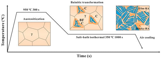
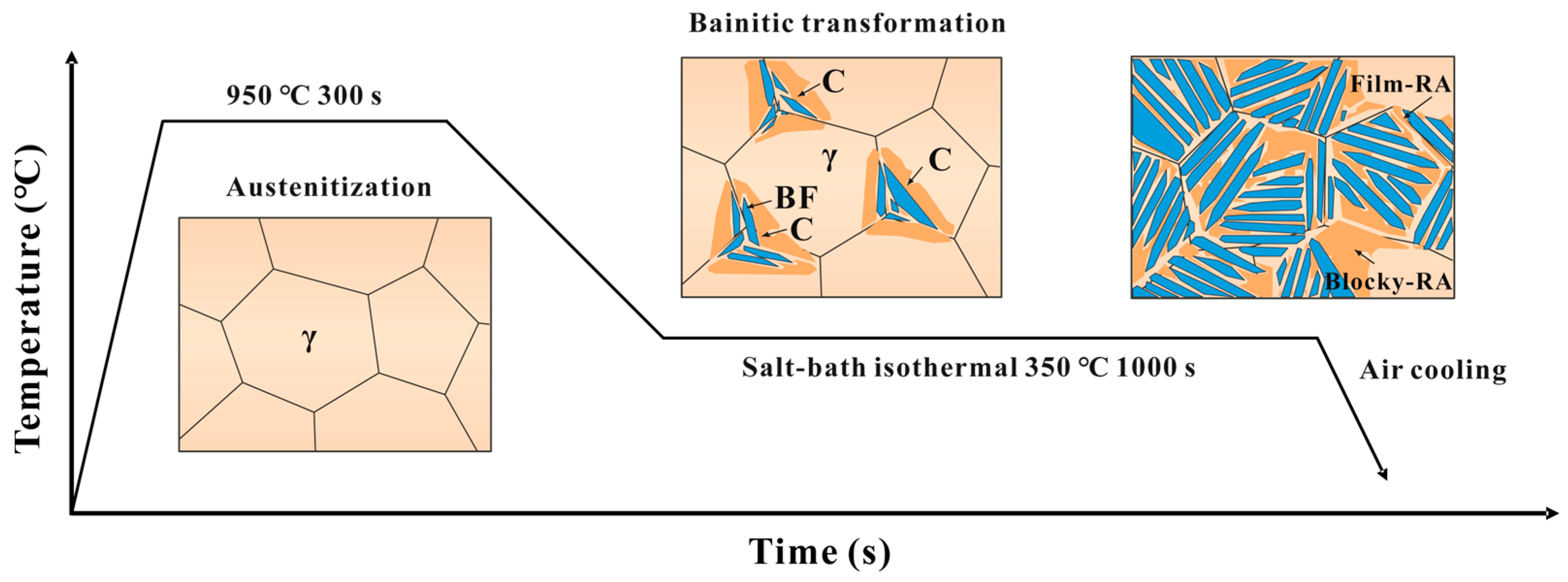
To obtain a CFB microstructure, the specimens were austenitized by heating to 950 °C at a rate of 10 °C/s in a SX2-10-12 high-temperature resistance furnace (Shanghai Shangdao Instrument Manufacturing Co., Ltd., Shanghai, China) and holding for 300 s. The specimens were then wrapped in insulating wool, rapidly transferred to a salt bath at 350 °C, and held for 1000 s to induce bainitic transformation. They were subsequently air-cooled to ambient temperature. The corresponding heat treatment schedule is presented in Figure 1.
Figure 1.
Heat treatment schedule.
SEM specimens measuring 10 mm × 10 mm × 4 mm were machined from the three heat-treated experimental steel plates. The specimens were ground using 400–1500 grit abrasive papers, mechanically polished on a P-2T metallographic sample polisher (Laizhou Weiyi Experimental Manufacture Co., Ltd., Laizhou, Shandong, China) with SiO2 polishing paste, and etched in 4 vol.% nital for 20 s. Specimens for EBSD analysis were electropolished in a solution of 10 vol.% HClO4 and 90 vol.% anhydrous ethanol at 20 V for 20 s. Microstructural observations were performed using a Sigma 300 field-emission scanning electron microscope (Carl Zeiss Microscopy GmbH, Jena, Germany). Electron backscatter diffraction (EBSD) data were acquired using an Oxford Instruments C-Nano detector (Oxford Instruments, High Wycombe, UK) at an accelerating voltage of 20 kV. EBSD measurements were performed on the rolling plane (RD–TD plane) of the experimental steel plates, where RD, TD, and ND denote the rolling, transverse, and normal directions, respectively. The inverse pole figure (IPF) maps were colored with respect to ND, corresponding to the Z0 axis of the sample coordinate system in AZtecCrystal 2.1. Five fields of view were analyzed for each steel. Body-centered cubic (BCC) regions and face-centered cubic (FCC) retained austenite (RA) were identified from the EBSD phase maps. FCC regions containing five or fewer pixels were excluded from the analysis. Boundaries with misorientation angles of 2–15° were classified as low-angle grain boundaries (LAGBs), whereas those with misorientation angles greater than 15° were classified as high-angle grain boundaries (HAGBs). RA morphology was classified according to its aspect ratio (AR). RA regions with AR ≤ 2.5 were classified as blocky-RA, whereas those with AR > 2.5 were classified as film-RA [28]. Prior austenite grains (PAGs) were reconstructed using AZtecCrystal, and the BCC orientation units within them were identified [29]. The BCC child grains were identified using a misorientation threshold of 5°. A window size of 20 pixels, a step width of 25%, an orientation voting threshold of 5°, and a parent grain boundary threshold of 10° were used for PAG reconstruction. These parameters were selected based on the recommended reconstruction settings in AZtecCrystal to distinguish BCC orientation variants and identify parent grain boundaries while limiting excessive segmentation. The Kurdjumov–Sachs (K–S) orientation relationship was adopted as the initial parent–child orientation relationship for PAG reconstruction because it is widely used to describe the crystallographic correspondence between austenite and bainitic ferrite in steels [30]. The density of BCC orientation units per unit PAG area ρBCC and the mean BCC orientation unit area were calculated using Equations (1) and (2), respectively.
where NBCC is the number of BCC orientation units within an individual PAG, and APAG is the area of that PAG (μm2). The mean number density was obtained by averaging the values calculated for individual PAGs across the five analyzed fields of view.
where n is the number of fields of view. ABCC,total,j is the total area (μm2) of the analyzed BCC orientation units in the jth field of view, Nj is the number of these units in that field, and j indexes the n fields of view analyzed for each steel.
XRD measurements were performed on specimens before and after tensile testing using a Rigaku SmartLab X-ray diffractometer (Rigaku, Tokyo, Japan). Specimens after deformation were excised from the uniform straight region within the original gauge length, outside the necked region and away from the shoulder transitions and grip sections. Cu Kα radiation was used over a 2θ range of 40–100° at a scanning rate of 2°/min. The XRD data were analyzed by Rietveld refinement using GSAS-II (revision 5782) to determine the RA volume fraction and lattice parameter [31]. Considering that the austenite lattice parameter is influenced not only by carbon content but also by substitutional alloying elements such as Mn, Si, and Al, the carbon content of RA (Cγ) was estimated using the empirical relation in Equation (3) [32].
where aγ is the austenite lattice parameter (Å).
TEM observations were performed using a Tecnai G2 F20 transmission electron microscope (FEI, Eindhoven, The Netherlands). TEM foils were prepared by twin-jet electropolishing in an electrolyte consisting of 10 vol.% perchloric acid and 90 vol.% anhydrous ethanol at −30 to −25 °C until perforation occurred at the specimen center. The BF lath thickness was measured using Image-Pro Plus 6.0 software based on multiple TEM fields of view. For each steel, at least 100 measurements of BF lath thickness were taken to determine the average thickness and corresponding standard deviation. All measurements were taken perpendicular to the lath interfaces to minimize directional measurement errors.
Dilatometric curves during isothermal holding were acquired using a DIL805 dilatometer (BÄHR Thermoanalyse GmbH, Hüllhorst, Germany). Cylindrical specimens 4 mm in diameter and 10 mm in length were subjected to the identical austenitization procedure illustrated in Figure 1, followed by cooling at 15 °C/s to simulate salt-bath cooling, isothermal holding at 350 °C for 1000 s, and final air cooling to room temperature. Time, temperature, and length variation were continuously recorded throughout the thermal cycle. To compare the isothermal transformation progress among the three steels, the dilatometric data were normalized according to Equation (4) [33]. To suppress the effects of data fluctuations on numerical differentiation, second-order local polynomial smoothing was adopted with a time window of 15 s. The smoothed data were subsequently differentiated based on actual time intervals to calculate the instantaneous transformation rate via Equation (5) [34,35]. Notably, a relative transformed fraction of 1 only represents the endpoint used for normalization, rather than indicating full transformation of austenite to bainite.
where Xr(t) is the relative transformed fraction at isothermal holding time t; ΔL(t) is the corresponding length change; ΔL0 and ΔLf are the length changes at the start and end of the isothermal transformation, respectively; and v is the instantaneous relative transformation rate.
Tensile tests were conducted in accordance with the Chinese standard GB/T 228.1-2021 [36] using a CMT5105 computer-controlled electronic universal testing machine (MTS Systems Co., Ltd., Hangzhou, China) at a crosshead speed of 1 mm/min. The tensile specimens had a parallel-section diameter of 5 mm, a gauge length of 25 mm, and an overall length of 60 mm, with M10 threaded ends. Three replicate specimens were tested for each steel, and the tensile properties are reported as the mean ± standard deviation. The yield strength was determined as the 0.2% proof stress (Rp0.2).
3. Results
3.1. Microstructural Characteristics
The JMatPro equilibrium phase calculations indicated that the temperatures at which the A0, A08, and A10 steels entered the single-phase austenite region were 834.6, 886.5, and 909.2 °C, respectively (Figure S1a–d). As Al progressively replaced Si, the calculated phase boundary temperature increased. Nevertheless, all three steels were predicted to be within the single-phase austenite region at 950 °C. Furthermore, the dilatometric curves of the three steels became nearly stable during holding at 950 °C (Figure S1e), with no obvious further length changes, suggesting that the austenitization process had largely reached completion. Together, these results supported the suitability of 950 °C as the austenitization temperature for all three experimental steels.
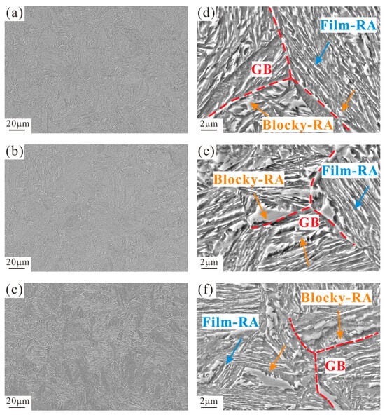
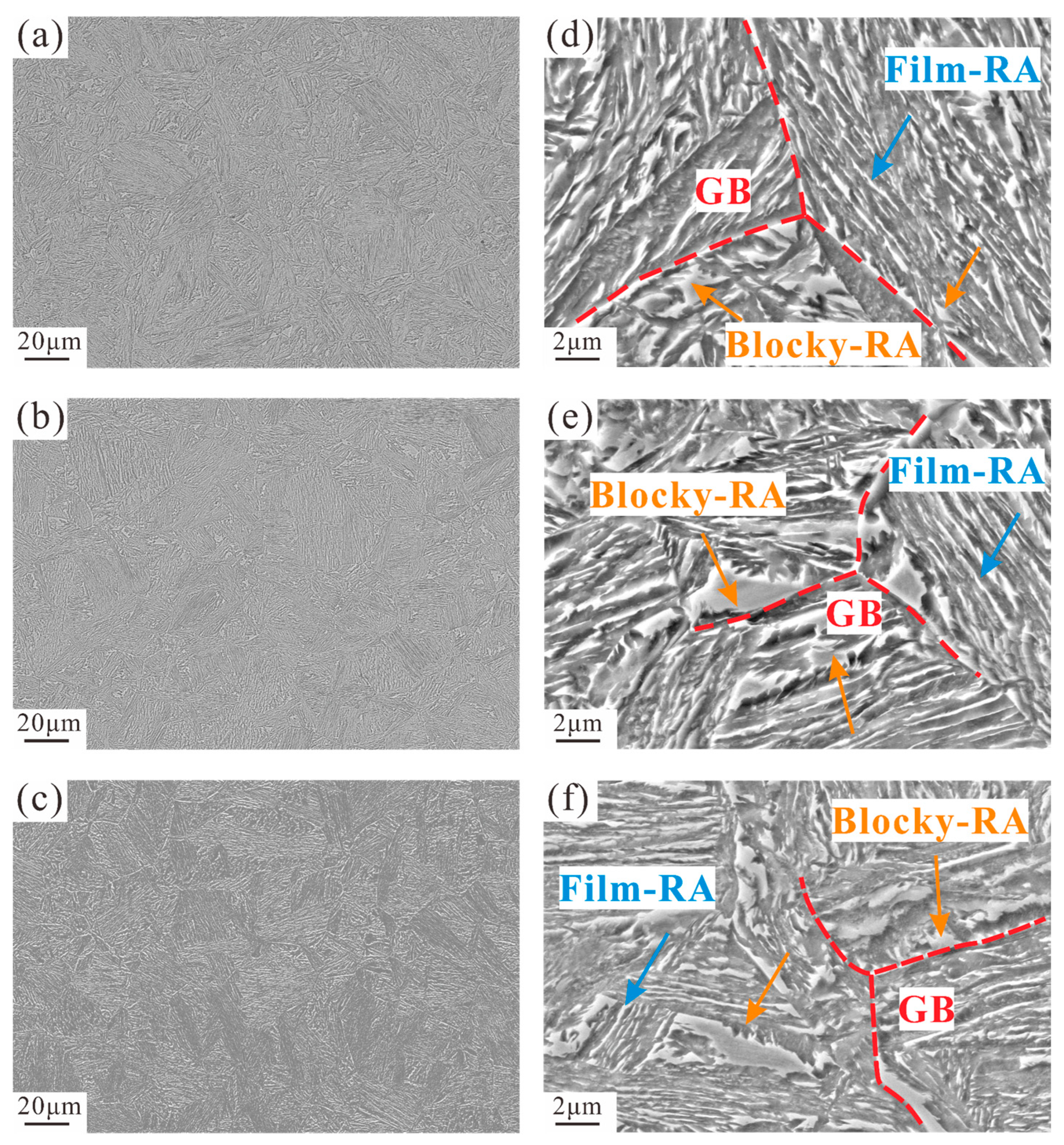
Figure 2 presents the SEM micrographs of the experimental steels with different Al/Si ratios after isothermal treatment. As shown in Figure 2a–c, all three steels were composed of lath-shaped bainitic ferrite and RA, with no obvious carbide precipitates detected. Figure 2d–f further illustrates the local morphologies of BF laths and RA. Two typical RA morphologies were identified: film-RA and blocky-RA. Film-RA was primarily distributed between BF lath subunits, while blocky-RA mainly resided at the junctions of adjacent bainitic sheaves and near grain boundaries (GBs). With increasing Al/Si ratio, blocky-RA appeared finer and less continuous. Meanwhile, the bainitic sheaves became more densely packed and interwoven.
Figure 2.
Scanning electron microscopy (SEM) micrographs of the experimental steels: (a–c) low-magnification images of A0, A08, and A10, respectively; (d–f) high-magnification images of A0, A08, and A10, respectively.
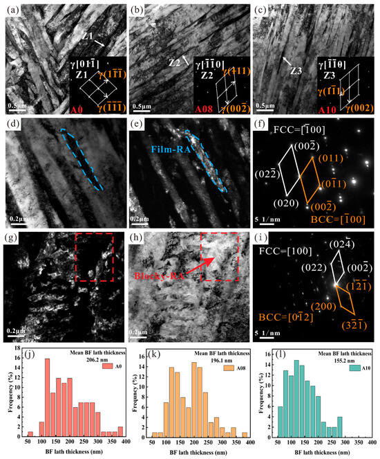
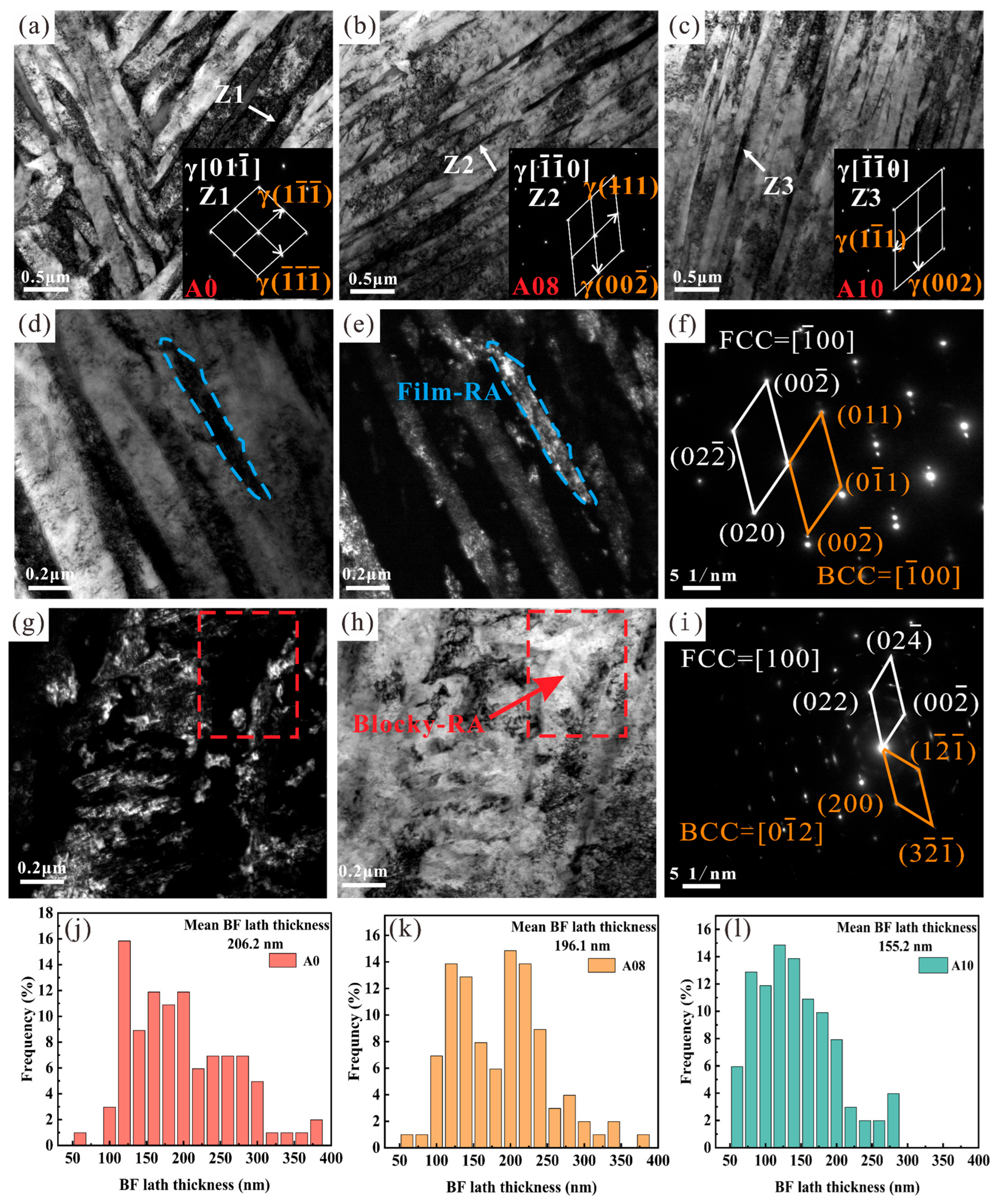
Figure 3 presents the TEM micrographs, selected-area electron diffraction (SAED) patterns, and BF lath thickness distributions of the three experimental steels. The bright-field TEM images in Figure 3a–c demonstrated that the three steels possessed a microstructure consisting of interwoven BF laths with interlath RA. Dense dislocation tangles were observed within BF laths, consistent with the displacive nature of bainitic transformation and the associated strain accommodation [37]. The indexing of SAED patterns acquired from interlath film-like regions (Z1, Z2, and Z3 in Figure 3a–c) revealed distinct diffraction spots of FCC austenite, verifying the existence of interlath film-RA. Consistent with the SEM observations, no cementite precipitates were detected within BF laths or at BF/austenite interfaces. Figure 3d–f presents the bright-field and dark-field TEM images of film-RA and the corresponding SAED pattern, while Figure 3g–i shows the corresponding characterization of blocky-RA. The indexed diffraction spots of both FCC austenite and the BCC ferrite matrix, together with the dark-field images, supported the identification of the retained austenite regions. The BF lath thickness distributions of A0, A08, and A10 are shown in Figure 3j–l, respectively. The average BF lath thickness decreased monotonically with increasing Al/Si ratio, declining from 206.2 nm in A0 to 196.1 nm in A08 and 155.2 nm in A10. The overall thickness distribution also shifted toward finer sizes, accompanied by a markedly increased proportion of BF laths thinner than 150 nm.
Figure 3.
Transmission electron microscopy (TEM) characterization of the experimental steels: (a–c) bright-field TEM images of BF laths in A0, A08, and A10, respectively, with corresponding selected-area electron diffraction (SAED) patterns shown in the insets; (d,e) bright-field and dark-field TEM images of Film-RA, respectively; (f) corresponding SAED pattern indexed for Film-RA; (g,h) dark-field and bright-field TEM images of Blocky-RA, respectively; (i) corresponding SAED pattern indexed for Blocky-RA; (j–l) BF lath thickness distributions in A0, A08, and A10, respectively.
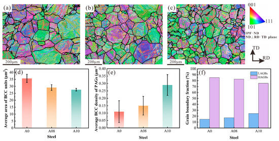
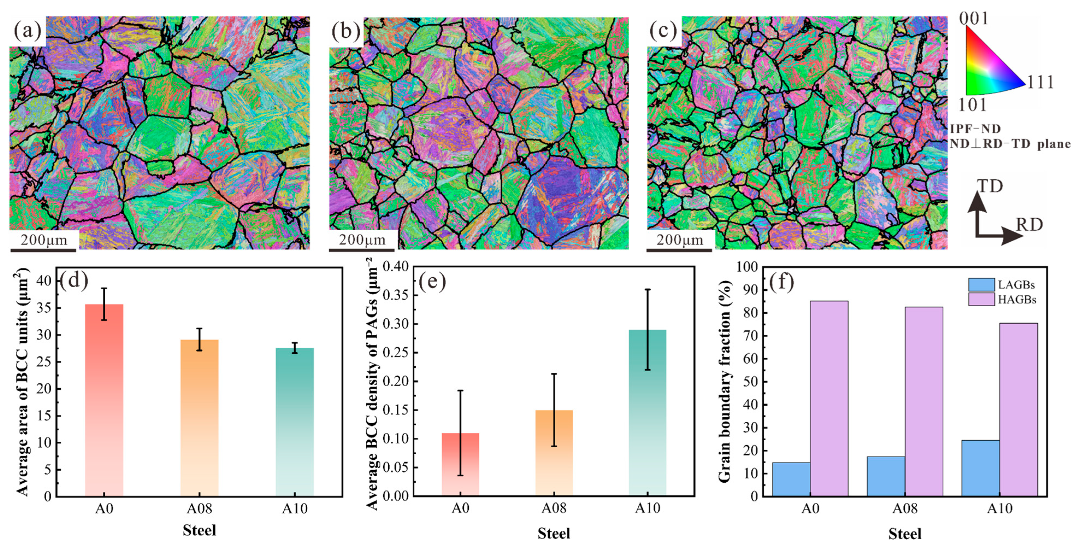
Figure 4 presents the EBSD characterization and PAG reconstruction results for the three experimental steels. Figure 4a–c shows the reconstructed PAGs and corresponding internal BCC orientation distributions. The A0 steel exhibited large regions with similar crystallographic orientations. These large uniform orientation regions were less prevalent in A08, where band-like orientation features became more prominent. For A10, the BCC orientation units were further refined and densely distributed. As summarized in Figure 4d, the average area of BCC orientation units decreased with increasing Al/Si ratio, declining from 35.71 μm2 in A0 to 29.15 μm2 in A08 and 27.59 μm2 in A10. Meanwhile, the number density of BCC orientation units per unit PAG area increased from 0.11 μm−2 in A0 and 0.15 μm−2 in A08 to 0.29 μm−2 in A10, with a larger increase from A08 to A10 (Figure 4e). Figure 4f displays the length fractions of HAGBs and LAGBs for the three steels. With the increase in the Al/Si ratio, the LAGB length fraction rose from 14.8% in A0 to 24.5% in A10, while the HAGB length fraction correspondingly decreased from 85.2% to 75.5%.
Figure 4.
Electron backscatter diffraction (EBSD) analysis results: (a–c) reconstructed prior austenite grain (PAG) maps of A0, A08, and A10, respectively; (d) mean body-centered cubic (BCC) orientation unit area; (e) number density of BCC orientation units per unit PAG area; (f) length fractions of Length fractions of high-angle grain boundaries (HAGBs) and low-angle grain boundaries (LAGBs).
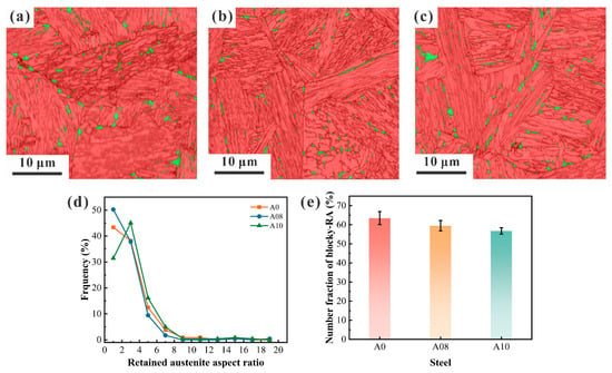
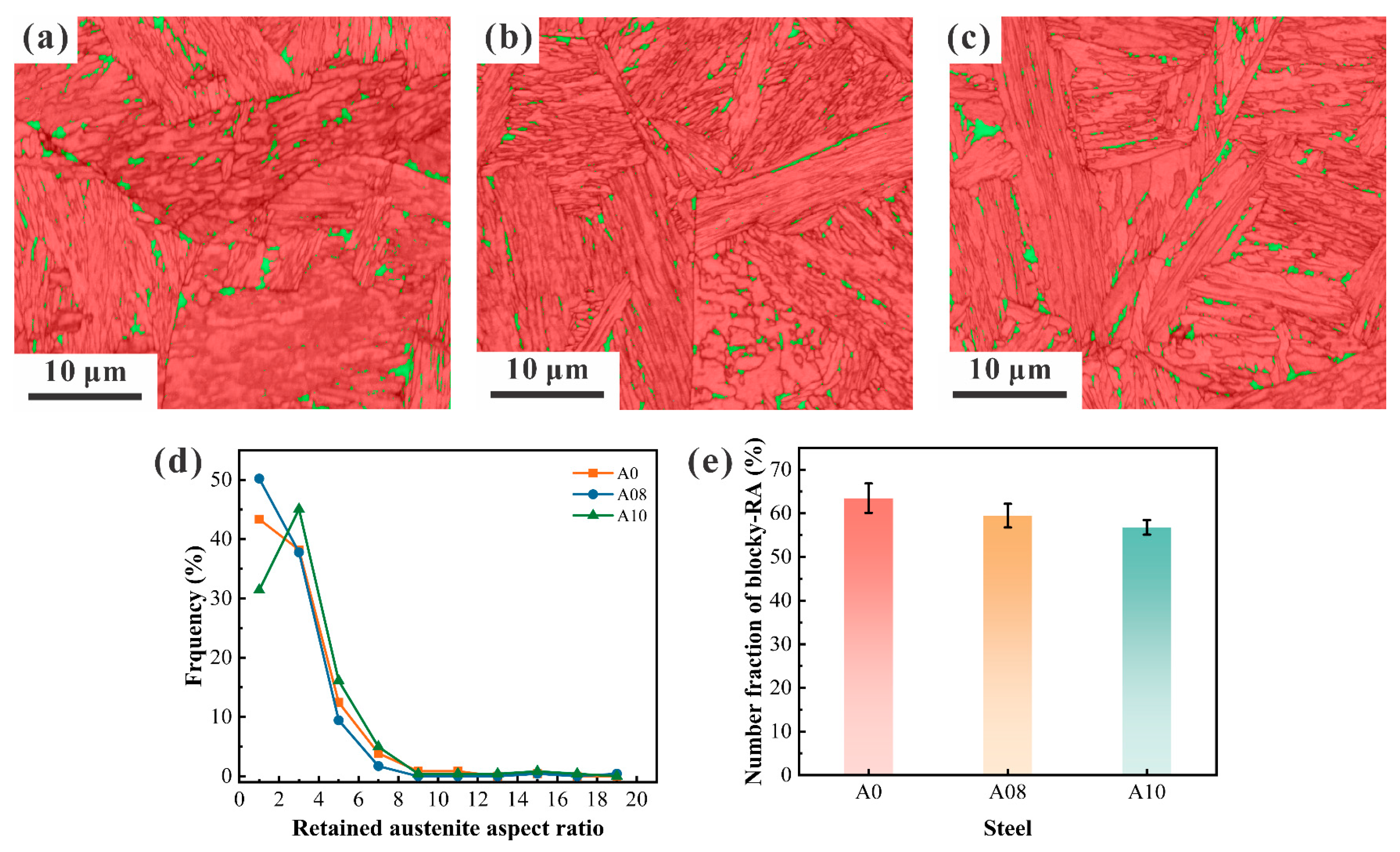
Figure 5a–c shows the EBSD phase maps of A0, A08, and A10, where red and green regions represent the indexed BCC and FCC phases, respectively. With increasing Al/Si ratio, the morphology of FCC-phase RA transformed from equiaxed blocky domains to elongated structures. The A10 steel exhibited a higher fraction of continuous and elongated FCC regions compared with A0 and A08. Figure 5d presents the frequency distributions of the RA aspect ratio for the three steels. The AR values of RA in all three steels mainly range from 1 to 5, and A10 exhibits a higher number fraction of film-RA than the other two steels. Increasing the Al/Si ratio shifts the overall AR distribution toward higher values. The number fraction of blocky-RA was quantified based on a critical AR threshold of 2.5, as illustrated in Figure 5e. The statistical results reveal that the proportion of blocky-RA gradually declines with the increase in the Al/Si ratio.
Figure 5.
RA morphology and blocky-RA statistics for steels with different Al/Si ratios: (a–c) EBSD phase maps; (d) frequency distributions of AR; (e) number fraction of blocky-RA.
3.2. XRD Characterization
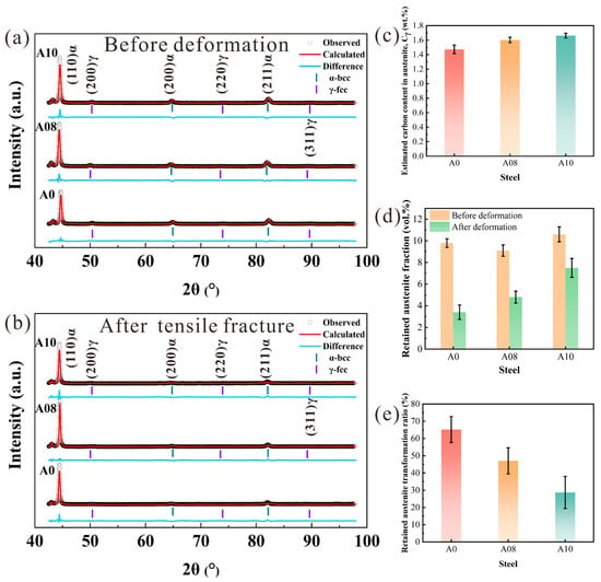
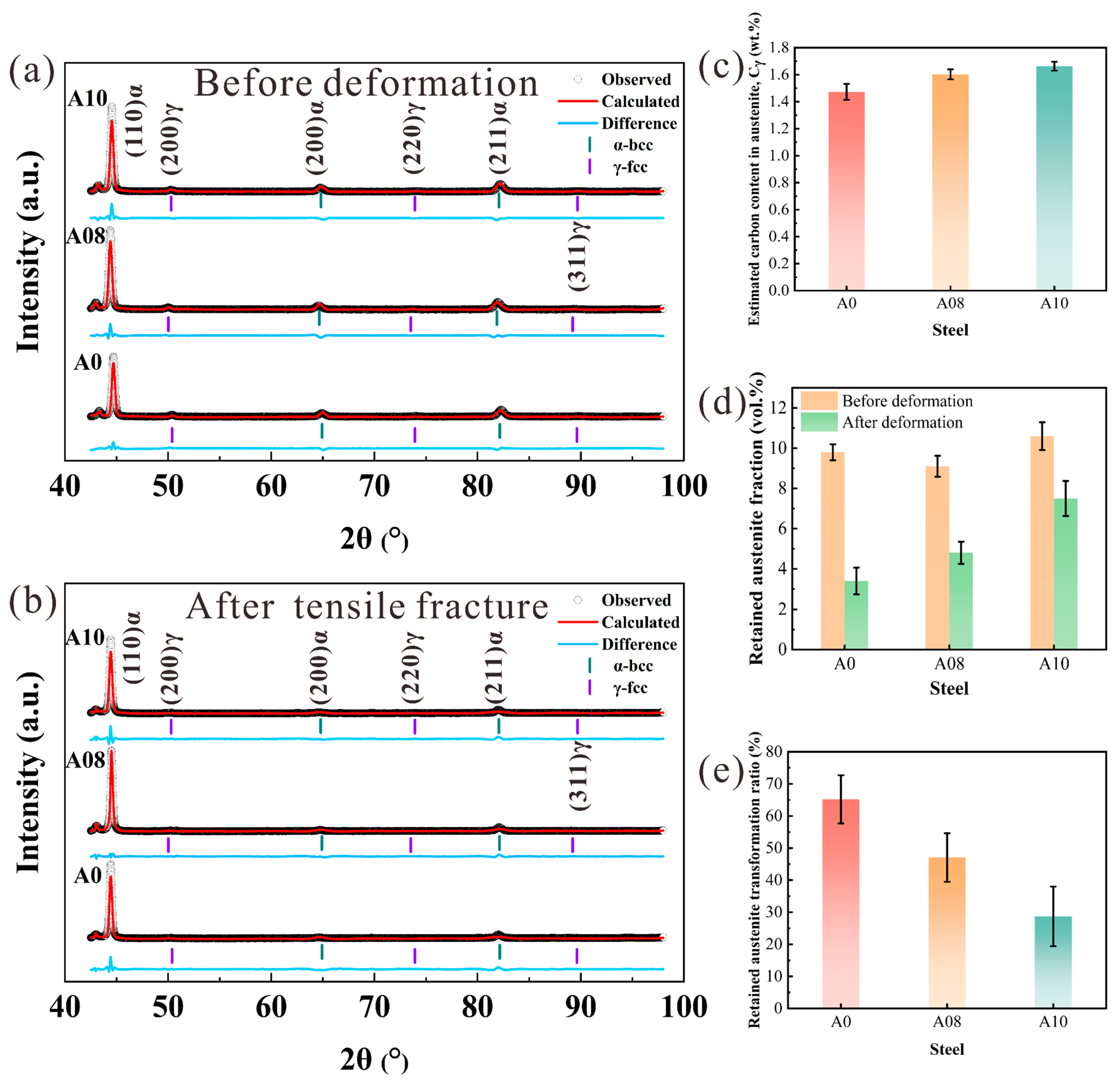
To characterize RA in the three steels, XRD measurements were conducted on specimens before and after tensile deformation, and the key results are summarized in Table 2. The BCC and FCC diffraction peaks were indexed in Figure 6a,b, following a presentation approach similar to that reported in a previous XRD study [38]. As presented in Figure 6a, only BCC and FCC diffraction peaks were identified in all samples, without distinct cementite diffraction signals. The initial RA volume fractions of A0, A08, and A10 were 9.8%, 9.1%, and 10.6%, respectively. Among all samples, A10 exhibited the largest austenite lattice parameter of 3.63299 Å. The austenite carbon contents calculated via Equation (3) are displayed in Figure 6c. The estimated RA carbon contents were 1.473, 1.603, and 1.663 wt.% for A0, A08, and A10.
Table 2.
XRD refinement results for the experimental steels.
Figure 6.
XRD analysis results: (a) diffraction patterns before deformation; (b) diffraction patterns after deformation; (c) estimated RA carbon content before deformation; (d) RA volume fractions before deformation and after tensile fracture; (e) cumulative fraction of RA transformed after tensile fracture. Error bars in (c–e) represent the standard deviations of three independent XRD measurements (n = 3).
To evaluate the mechanical stability of RA among the three steels, the RA fraction after tensile fracture was further analyzed. Figure 6b shows the XRD patterns of specimens after tensile deformation. All three steels exhibited a reduced RA fraction after fracture compared with their initial state. A quantitative comparison of RA volume fractions before and after tensile testing is provided in Figure 6d. The transformed RA fraction during tensile deformation was determined based on the measured RA contents before and after testing [39].
As shown in Figure 6e, the cumulative transformed RA fractions were 65.3%, 47.3%, and 29.2% for A0, A08, and A10, respectively. The transformed fraction decreased gradually with increasing Al/Si ratio, which corresponds to the elevated carbon content and morphological evolution of RA.
3.3. Isothermal Bainitic Transformation
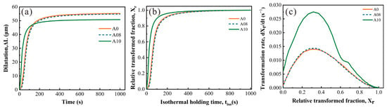
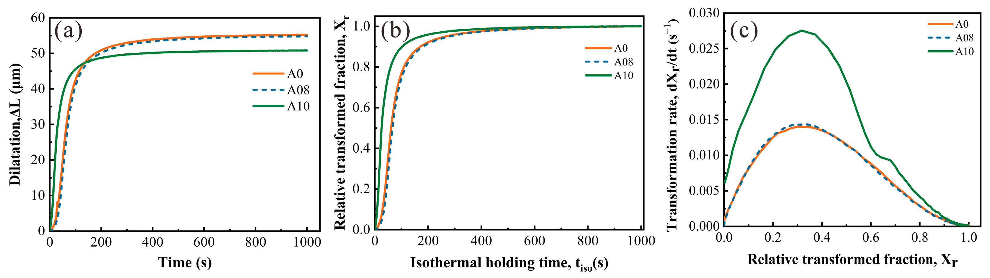
Figure 7a presents the dilatometric curves of the three steels during isothermal holding at 350 °C. For all experimental steels, the length change increased rapidly at the initial stage and then gradually plateaued with prolonged holding time. The A10 steel exhibited a steeper slope during the rapid expansion stage and reached a plateau earlier. After 1000 s of isothermal holding, the final length change declined with increasing Al/Si ratio, with values of 55.3 μm, 54.8 μm, and 50.8 μm for A0, A08, and A10, respectively. Figure 7b displays the normalized relative transformed fraction curves. The transformation curves of A0 and A08 showed similar trends, while the curve of A10 shifted toward shorter holding times, presenting higher relative transformed fractions throughout the early and intermediate transformation stages. Figure 7c illustrates the instantaneous relative transformation rate as a function of the relative transformed fraction. For all three steels, the transformation rate first rises and then declines, peaking at a relative transformed fraction of approximately 0.3. A10 achieved a maximum transformation rate of 0.0275 s−1, which is considerably higher than the peak rates of A0 (0.0140 s−1) and A08 (0.0144 s−1). These findings demonstrate that A10 exhibits faster relative transformation kinetics during the early and intermediate stages.
Figure 7.
Bainitic transformation behavior of the experimental steels at 350 °C: (a) original dilatometric curves; (b) relative transformed fraction Xr as a function of isothermal holding time; (c) transformation rate dXr/dt as a function of relative transformed fraction Xr.
3.4. Tensile Properties
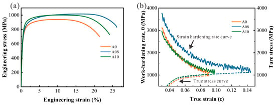
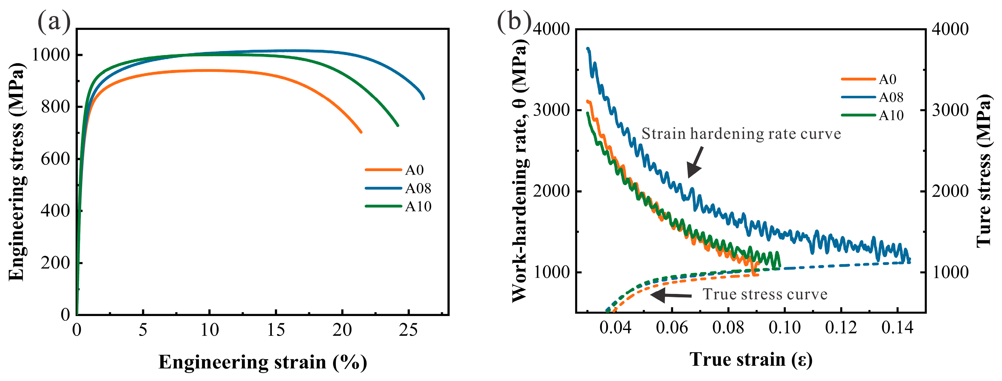
Figure 8a shows the engineering stress–strain curves of the three experimental steels, and the corresponding tensile properties are summarized in Table 3. The A0 steel with an Al/Si ratio of 0 exhibited a yield strength (YS) of 655.9 ± 12 MPa, an ultimate tensile strength (UTS) of 940.5 ± 16 MPa, and an elongation after fracture (EL) of 21 ± 0.7%. The YS increased progressively with increasing Al/Si ratio, reaching 741.3 ± 11 MPa in A10. A08 and A10 exhibited comparable UTS values of 1016.3 ± 15 MPa and 1001.0 ± 17 MPa, respectively. By contrast, the EL varied non-monotonically with increasing Al/Si ratio, first increasing and then decreasing, with the maximum elongation of 26 ± 0.4% achieved in the A08 steel.
Figure 8.
Tensile behavior of the experimental steels: (a) engineering stress–strain curves of the experimental steels; (b) strain-hardening rate and true stress as functions of true strain during uniform deformation, with solid and dashed lines representing the strain-hardening rate and true stress, respectively.
Table 3.
Tensile properties of the experimental steels.
Figure 8b presents the strain-hardening rate and true stress plotted against true strain for the three steels. According to the Considère criterion for necking instability, the true strain at the intersection of the strain-hardening rate and true stress curves defines the maximum uniform true strain. For all three steels, the strain-hardening rate continuously decreases with increasing true strain. Notably, the A08 steel maintained a higher strain-hardening rate over a wide true strain range, which effectively delays the initiation of necking. Previous studies have demonstrated that RA can enhance strain hardening and retard plastic instability via the TRIP effect during tensile deformation [10,40].
4. Discussion
4.1. Effects of the Al/Si Ratio on Bainitic Transformation and Lath Refinement
As indicated in Figure 3j–l, the increase in Al/Si ratio effectively refined BF lath microstructures. The average BF lath thickness decreased by 10.1 nm from A0 to A08 and by 40.9 nm from A08 to A10. The latter reduction is approximately four times the former.
The BF lath size is highly dependent on the generation of nucleation sites, the evolution of available growth space, and the mutual interaction of adjacent laths during bainitic transformation. As revealed in Figure 7b,c, A10 exhibited a higher relative transformation rate during the early and intermediate transformation stages. Among the three experimental steels, A10 possessed the highest number density and the smallest average area of BCC orientation units within PAGs (Figure 4d,e), demonstrating its significantly refined orientation subdivision. Pre-existing BF laths can serve as autocatalytic nucleation sites for newly formed BF subunits, facilitating continuous bainite propagation [41]. The sustained formation of BF laths further subdivides untransformed austenite grains, limits the growth space for subsequent lath development, and increases impingement between neighboring BF laths. The growth of newly formed BF laths is restrained when encountering pre-formed bainite laths or grain boundaries, ultimately generating finer and more compactly distributed BF lath structures [25,42]. The densely interwoven lath morphology characterized by SEM, combined with the reduced lath thickness quantified by TEM, confirms that microstructural subdivision and inter-lath growth restriction collectively dominate the BF refinement mechanism in the A10 steel.
A10 exhibited an accelerated relative transformation rate in the early and intermediate transformation stages but exhibited the smallest final length change after isothermal holding. The refined BF lath structure and subdivided crystallographic orientations within the PAGs of A10 indicate that untransformed austenite is gradually trapped in localized microscale regions as transformation progresses. This spatial confinement imposes severe restrictions on the growth space for newly nucleated BF laths and hinders the accommodation of transformation-induced strain. Meanwhile, continuous carbon partitioning from formed BF to untransformed austenite raises the carbon concentration of untransformed austenite, which lowers the chemical driving force for subsequent bainitic transformation and further suppresses BF proliferation during prolonged isothermal holding [43]. Nevertheless, variations in Al and Si contents can modify the lattice parameters of both BCC and FCC phases and alter the magnitude of transformation strain. For this reason, the reduced final length change of A10 cannot be simply ascribed to a lower bainite fraction. Accurate interpretation of dilatometric signals requires quantitative calibration with actual phase fractions and transformation strain variations.
4.2. RA Stability
RA enhances strain hardening via the TRIP effect, and its mechanical stability significantly governs the initiation and evolution of phase transformation. The Al/Si ratio-induced variations in RA carbon content and BF lath refinement respectively modulate the chemical driving force for RA transformation and the microstructural constraints imposed by the surrounding matrix. Accordingly, the stability of RA should be comprehensively evaluated from two critical aspects: chemical stability and localized microstructural confinement.
The data listed in Table 2 reveal distinct differences in the final carbon content of RA across steels with varying Al/Si ratios. The elevated carbon concentration within RA of the A10 steel reduces the chemical driving force for austenite-to-martensite transformation and depresses the martensite start temperature [44]. The decreased chemical driving force necessitates a greater contribution from externally applied mechanical driving force, which increases the critical local stress required to trigger RA transformation. As a result, the RA in A10 exhibited greater resistance to transformation during tensile deformation, allowing a larger fraction of RA to remain after fracture.
The austenite-to-martensite transformation is accompanied by shear deformation and volume expansion, which must be accommodated by elastic and plastic deformation of the surrounding matrix microstructure [45]. Fine interlath film-RA is tightly constrained by adjacent BF laths, which effectively restricts the occurrence of martensitic transformation and endows film-RA with superior mechanical stability [46]. In contrast, coarse blocky-RA presents lower mechanical stability and is prone to stress concentration, thereby promoting martensitic transformation under external loading [7]. As discussed in Section 4.1, increasing the Al/Si ratio facilitates the subdivision of untransformed austenite within prior austenite grains. A greater amount of austenite is retained between densely distributed BF laths and extends along BF interfaces. The transverse size of RA is confined by interlath spacing, generating elongated film-RA structures. This morphological evolution increases the fraction of RA with an aspect ratio greater than 2.5 and reduces the proportion of unstable blocky-RA.
The higher cumulative transformed fraction of RA in A0, combined with its lower RA carbon content and higher fraction of blocky-RA, demonstrates a stronger tendency for strain-induced RA transformation. Accordingly, the TRIP effect primarily concentrates during the early stage of tensile deformation [27], which limits the sustained strain-hardening capacity. The A08 steel exhibited moderate carbon enrichment and BF lath refinement, leading to an intermediate RA transformation tendency. By comparison, A10 exhibited the highest RA mechanical stability, which can be attributed to its elevated carbon enrichment in RA and the enhanced microstructural constraints imposed by the densely refined surrounding BF lath matrix.
4.3. Combined Effects of Bainitic Lath Refinement and RA Stability
BF lath interfaces and internal dislocation substructures strongly govern the yielding behavior by impeding dislocation motion. Finer BF laths provide a greater number of interfacial barriers during dislocation glide and shorten the effective slip distance, thereby increasing the critical stress required to initiate plastic deformation [47]. Additionally, dislocation substructures generated during bainitic transformation further contribute to matrix strengthening. Dislocation arrays associated with LAGBs can effectively interact with gliding dislocations and enhance the resistance to plastic flow [47,48]. The A10 steel exhibited the highest LAGB length fraction among the three samples, which, together with the dense dislocation tangles observed via TEM, verifies the strengthening contribution of refined internal substructures. Collectively, the synergistic effects of dense lath interfaces and intricate dislocation substructures are responsible for the improved yield strength of A10.
Post-yield strain hardening is closely correlated with matrix dislocation evolution and strain-induced RA transformation. Local stress redistribution and dislocation multiplication triggered by martensitic transformation substantially improve the strain-hardening capability of the matrix [49]. Although A0 exhibited the highest cumulative transformed RA fraction, its strain-hardening behavior was less sustained than that of A08, demonstrating that a greater cumulative fraction of transformed RA does not guarantee continuous strain hardening. Similarly, A10 achieved superior RA mechanical stability but exhibited lower strain-hardening capacity and EL than A08. By contrast, A08 with moderate RA stability delivers the most sustained strain-hardening response. This phenomenon indicates that a favorable strength–ductility balance requires an appropriate balance between the RA transformation tendency and the matrix plastic deformation capacity. Similarly, Zhao et al. reported that moderate RA stability promoted sustained strain hardening through the TRIP effect in an Al-containing CFB steel, whereas excessive RA stability suppressed the TRIP contribution [50].
The effect of strain hardening on plastic instability further clarifies the differences in EL among the three steels. A08 maintains a higher strain-hardening rate over a broad true strain range, and this rate decreases gradually with strain. The intersection of its strain-hardening rate and true stress curves occurs at a higher true strain, corresponding to an extended uniform deformation interval. Therefore, the enhanced yield strength of A10 is primarily attributed to BF lath refinement and internal substructure strengthening. In comparison, the sustained strain-hardening behavior of A08 effectively delays the occurrence of plastic instability. A08 therefore combines a UTS comparable to that of A10 with a higher EL.
5. Conclusions
This study investigated the microstructure and tensile properties of CFB steels with a nominal total Si + Al content of 1.8 wt.% after isothermal holding at 350 °C for 1000 s, focusing on the effects of the Al/Si ratio on BF lath size, RA stability, and mechanical properties. The main conclusions are as follows:
- Increasing the Al/Si ratio promoted lath refinement. The mean BF lath thickness decreased from 206.2 nm in A0 to 196.1 nm in A08 and 155.2 nm in A10. The faster transformation during the early and intermediate stages in A10 was accompanied by a higher density of BCC orientation units per unit PAG area and a smaller mean BCC orientation unit area, indicating that PAG subdivision and mutual constraints between neighboring BF laths contributed to lath refinement.
- With increasing Al/Si ratio, the estimated RA carbon content increased from 1.473 wt.% in A0 to 1.603 wt.% in A08 and 1.663 wt.% in A10. The cumulative fractions of RA transformed during tensile testing to fracture were 65.3%, 47.3%, and 29.2%, respectively. The tendency for RA transformation decreased with increasing Al/Si ratio, corresponding to changes in carbon enrichment and RA morphology.
- As the Al/Si ratio increased from 0.82 to 1.29, YS increased further, while UTS decreased slightly by 15.3 MPa and EL also declined. A10 achieved the highest YS of 741.3 ± 11 MPa, corresponding to its refined BF laths and internal substructures. A08 exhibited more sustained strain hardening, achieving a UTS of 1016.3 ± 15 MPa and an EL of 26 ± 0.4%, providing a favorable strength–ductility balance.
Supplementary Materials
The following supporting information can be downloaded at: https://www.mdpi.com/article/10.3390/met16111264/s1, Figure S1: Equilibrium phase calculations and dilatometric measurements for the experimental steels. (a–c) Equilibrium phase fractions as a function of temperature calculated using JMatPro for A0, A08, and A10, respectively. (d) Calculated temperatures at which each steel entered the single-phase austenite region. (e) Dilatometric curves showing the change in specimen length during holding at 950 °C.
Author Contributions
Conceptualization, H.Z. and X.Z.; Methodology, H.Z.; Validation, Z.Q.; Formal Analysis, H.Z.; Investigation, H.Z. and Z.Q.; Resources, J.L. and X.Z.; Data Curation, H.Z., Z.Q. and D.L.; Writing—Original Draft Preparation, H.Z.; Writing—Review and Editing, Z.Q., D.L., J.L. and X.Z.; Visualization, H.Z.; Supervision, X.Z.; Project Administration, J.L. and X.Z. All authors have read and agreed to the published version of the manuscript.
Funding
This research received no external funding.
Data Availability Statement
The original contributions presented in this study are included in the article/Supplementary Material. Further inquiries can be directed to the corresponding author.
Conflicts of Interest
The authors declare no conflicts of interest.
References
- Jiang, J.; Chen, Z.; Ma, H.; Xing, H.; Li, X. Strength-ductility synergy in heterogeneous-structured metals and alloys. Matter 2022, 5, 2430–2433. [Google Scholar] [CrossRef] [Scilit]
- Xu, N.; Wang, L.; Hu, J.; Chai, Z.; Zhao, W.; Xu, W. Promoting ductility and formability in a carbide free bainitic steel via pre-annealing treatment. Mater. Charact. 2023, 204, 113205. [Google Scholar] [CrossRef] [Scilit]
- Bhadeshia, H.K.D.H.; Edmonds, D.V. Bainite in silicon steels: New composition–property approach Part 1. Met. Sci. 1983, 17, 411–419. [Google Scholar] [CrossRef] [Scilit]
- Bhadeshia, H.K.D.H.; Edmonds, D.V. Bainite in silicon steels: New composition–property approach Part 2. Met. Sci. 1983, 17, 420–425. [Google Scholar] [CrossRef] [Scilit]
- Yoozbashi, M.N.; Yazdani, S. XRD and TEM study of bainitic ferrite plate thickness in nanostructured, carbide free bainitic steels. Mater. Chem. Phys. 2015, 160, 148–154. [Google Scholar] [CrossRef] [Scilit]
- He, T.; Wang, L.; Hu, F.; Zhou, W.; Zhang, Z.; Wu, K. Stability of retained austenite and work hardening behavior in ultra-fine medium carbon bainitic steel. J. Mater. Res. Technol. 2023, 22, 2690–2703. [Google Scholar] [CrossRef] [Scilit]
- Zhao, J.; Zhang, F. In-situ observation of tensile deformation and retained austenite transformation behaviors in carbide-free bainitic steel. Mater. Sci. Eng. A 2020, 771, 138637. [Google Scholar] [CrossRef] [Scilit]
- Caballero, F.G.; García-Mateo, C.; Chao, J.; Santofimia, M.J.; Capdevila, C.; de Andrés, C.G. Effects of Morphology and Stability of Retained Austenite on the Ductility of TRIP-aided Bainitic Steels. ISIJ Int. 2008, 48, 1256–1262. [Google Scholar] [CrossRef] [Scilit]
- Huang, X.; Huang, Q.; Jiang, Y.; Li, Z.; Shan, Q. Retained austenite stability in cementite-free bainitic steels processed by different isothermal heat treatments: Insights from quasi-in situ strain partition analysis. Mater. Charact. 2025, 229, 115474. [Google Scholar] [CrossRef] [Scilit]
- Hasan, S.M.; Mandal, A.; Singh, S.B.; Chakrabarti, D. Work hardening behaviour and damage mechanisms in carbide-free bainitic steel during uni-axial tensile deformation. Mater. Sci. Eng. A 2019, 751, 142–153. [Google Scholar] [CrossRef] [Scilit]
- Kozeschnik, E.; Bhadeshia, H.K.D.H. Influence of silicon on cementite precipitation in steels. Mater. Sci. Technol. 2008, 24, 343–347. [Google Scholar] [CrossRef] [Scilit]
- Lin, S.; Borgenstam, A.; Stark, A.; Hedström, P. Effect of Si on bainitic transformation kinetics in steels explained by carbon partitioning, carbide formation, dislocation densities, and thermodynamic conditions. Mater. Charact. 2022, 185, 111774. [Google Scholar] [CrossRef] [Scilit]
- Franceschi, M.; Pezzato, L.; Gennari, C.; Hanoz, D.; Bertolini, R.; Fabrizi, A.; Polyakova, M.; Brunelli, K.; Bonollo, F.; Dabalà, M. Influence of Austempering Temperature on Microstructure and Mechanical Properties of High-Silicon Carbide-Free Bainitic Steel. Steel Res. Int. 2023, 94, 2200821. [Google Scholar] [CrossRef] [Scilit]
- Zhang, S.; Zhou, W.; Hu, F.; Yershov, S.; Wu, K. The role of Si in enhancing the stability of residual austenite and mechanical properties of a medium carbon bainitic steel. J. Mater. Res. Technol. 2024, 30, 1939–1949. [Google Scholar] [CrossRef] [Scilit]
- Królicka, A.; Garcia Caballero, F.; Zalecki, W.; Kuziak, R.; Rozmus, R. Controlling the Thermal Stability of a Bainitic Structure by Alloy Design and Isothermal Heat Treatment. Materials 2023, 16, 2963. [Google Scholar] [CrossRef] [Scilit]
- Huang, H.; Sherif, M.Y.; Rivera-Díaz-del-Castillo, P.E.J. Combinatorial optimization of carbide-free bainitic nanostructures. Acta Mater. 2013, 61, 1639–1647. [Google Scholar] [CrossRef] [Scilit]
- Huang, J.; Le, G.; Ding, S.; Zang, C.; Chen, H.; Dai, P.; Tang, Z. Effect of Al Substitution of Si on the Microstructure, Retained Austenite Stability and Mechanical Properties of Low-Alloyed TRIP-Aided Steels. Metals 2026, 16, 379. [Google Scholar] [CrossRef] [Scilit]
- Tian, J.Y.; Xu, G.; Zhou, M.X.; Hu, H.J.; Xue, Z.L. Effects of Al addition on bainite transformation and properties of high-strength carbide-free bainitic steels. J. Iron Steel Res. Int. 2019, 26, 846–855. [Google Scholar] [CrossRef] [Scilit]
- Gulbay, O.; Gramlich, A.; Krupp, U. Effects of Silicon and Aluminum Alloying on Phase Transformation and Microstructure Evolution in Fe–0.2C–2.5Mn Steel: Insights from Continuous–Cooling–Transformation and Time–Temperature–Transformation Diagrams. Steel Res. Int. 2024, 95, 2400159. [Google Scholar] [CrossRef] [Scilit]
- Qian, L.; Zhou, Q.; Zhang, F.; Meng, J.; Zhang, M.; Tian, Y. Microstructure and mechanical properties of a low carbon carbide-free bainitic steel co-alloyed with Al and Si. Mater. Des. 2012, 39, 264–268. [Google Scholar] [CrossRef] [Scilit]
- Kantanen, P.; Somani, M.; Kaijalainen, A.; Haiko, O.; Porter, D.; Kömi, J. Microstructural Characterization and Mechanical Properties of Direct Quenched and Partitioned High-Aluminum and High-Silicon Steels. Metals 2019, 9, 256. [Google Scholar] [CrossRef] [Scilit]
- Zhu, K.; Mager, C.; Huang, M. Effect of substitution of Si by Al on the microstructure and mechanical properties of bainitic transformation-induced plasticity steels. J. Mater. Sci. Technol. 2017, 33, 1475–1486. [Google Scholar] [CrossRef] [Scilit]
- Rana, R.; Cordova-Tapia, E.; Morales-Rivas, L.; Jimenez, J.A.; Garcia-Mateo, C. Mechanical behaviour and microstructural characteristics of high-silicon ultra-strong bainitic steels for hot rolling practice. Mater. Sci. Eng. A 2025, 931, 148236. [Google Scholar] [CrossRef] [Scilit]
- Mertens, A.; Jacques, P.J.; Sietsma, J.; Delannay, F. Relative Influences of Aluminium and Silicon on the Kinetics of Bainite Formation from Intercritical Austenite. Steel Res. Int. 2008, 79, 954–959. [Google Scholar] [CrossRef] [Scilit]
- Franceschi, M.; Jimenez, J.A.; dos Santos Avila, D.; Garcia-Mateo, C. The role of prior austenite grain size in the kinetics and morphology of carbide-free bainite. J. Mater. Res. Technol. 2026, 43, 3842–3851. [Google Scholar] [CrossRef] [Scilit]
- Guo, L.; Roelofs, H.; Lembke, M.I.; Bhadeshia, H.K.D.H. Modelling of size distribution of blocky retained austenite in Si-containing bainitic steels. Mater. Sci. Technol. 2018, 34, 54–62. [Google Scholar] [CrossRef] [Scilit]
- Zhao, F.; Chen, P.; Xu, B.; Yu, Q.; Misra, R.D.K.; Wang, G.; Yi, H. Martensite transformation of retained austenite with diverse stability and strain partitioning during tensile deformation of a carbide-free Bainitic steel. Mater. Charact. 2021, 179, 111327. [Google Scholar] [CrossRef] [Scilit]
- Cheng, Y.Y.; Zhao, G.; Xu, D.M.; Mao, X.P.; Bao, S.Q.; Yang, G.W. Comparative study on microstructures and mechanical properties of Q&P steels prepared with hot-rolled and cold-rolled C–Si–Mn sheets. J. Mater. Res. Technol. 2022, 20, 1226–1242. [Google Scholar] [CrossRef] [Scilit]
- Nyyssönen, T.; Isakov, M.; Peura, P.; Kuokkala, V.T. Iterative Determination of the Orientation Relationship Between Austenite and Martensite from a Large Amount of Grain Pair Misorientations. Metall. Mater. Trans. A 2016, 47, 2587–2590. [Google Scholar] [CrossRef] [Scilit]
- Yardley, V.A.; Payton, E.J. Austenite–martensite/bainite orientation relationship: Characterisation parameters and their application. Mater. Sci. Technol. 2014, 30, 1125–1130. [Google Scholar] [CrossRef] [Scilit]
- Toby, B.H.; Von Dreele, R.B. GSAS-II: The genesis of a modern open-source all purpose crystallography software package. J. Appl. Crystallogr. 2013, 46, 544–549. [Google Scholar] [CrossRef] [Scilit]
- Toji, Y.; Matsuda, H.; Herbig, M.; Choi, P.P.; Raabe, D. Atomic-scale analysis of carbon partitioning between martensite and austenite by atom probe tomography and correlative transmission electron microscopy. Acta Mater. 2014, 65, 215–228. [Google Scholar] [CrossRef] [Scilit]
- Pei, W.; Liu, W.; Zhang, Y.; Qie, R.; Zhao, A. Study on kinetics of transformation in medium carbon steel bainite at different isothermal temperatures. Materials 2021, 14, 2721. [Google Scholar] [CrossRef] [Scilit]
- Xu, Y.; Xu, G.; Mao, X.; Zhao, G.; Bao, S. Method to evaluate the kinetics of bainite transformation in low-temperature nanobainitic steel using thermal dilatation curve analysis. Metals 2017, 7, 330. [Google Scholar] [CrossRef] [Scilit]
- Santajuana, M.A.; Eres-Castellanos, A.; Ruiz-Jimenez, V.; Allain, S.; Geandier, G.; Caballero, F.G.; Garcia-Mateo, C. Quantitative assessment of the time to end bainitic transformation. Metals 2019, 9, 925. [Google Scholar] [CrossRef] [Scilit]
- GB/T 228.1-2021; Metallic Materials—Tensile Testing—Part 1: Method of Test at Room Temperature. Standards Press of China: Beijing, China, 2021.
- Zhu, J.; Barber, G.; Sun, X. Effects of Isothermal Temperature on Dislocation Density in Bainite Transformation of 4140 Steel. Materials 2022, 15, 6066. [Google Scholar] [CrossRef] [Scilit]
- Rozo Vasquez, J.; Arian, B.; Kersting, L.; Homberg, W.; Trächtler, A.; Walther, F. Detection of Phase Transformation during Plastic Deformation of Metastable Austenitic Steel AISI 304L by Means of X-ray Diffraction Pattern Analysis. Metals 2023, 13, 1007. [Google Scholar] [CrossRef] [Scilit]
- Shi, W.; Li, L.; Yang, C.X.; Fu, R.Y.; Wang, L.; Wollants, P. Strain-induced transformation of retained austenite in low-carbon low-silicon TRIP steel containing aluminum and vanadium. Mater. Sci. Eng. A 2006, 429, 247–251. [Google Scholar] [CrossRef] [Scilit]
- Long, X.; Zhao, G.; Zhang, F.; Xu, S.; Yang, Z.; Du, G.; Branco, R. Evolution of tensile properties with transformation temperature in medium-carbon carbide-free bainitic steel. Mater. Sci. Eng. A 2020, 775, 138964. [Google Scholar] [CrossRef] [Scilit]
- Ravi, A.M.; Sietsma, J.; Santofimia, M.J. Exploring bainite formation kinetics distinguishing grain-boundary and autocatalytic nucleation in high and low-Si steels. Acta Mater. 2016, 105, 155–164. [Google Scholar] [CrossRef] [Scilit]
- Sainis, S.; Farahani, H.; Gamsjäger, E.; van der Zwaag, S. An in-situ LSCM study on bainite formation in a Fe-0.2C-1.5Mn-2.0Cr alloy. Metals 2018, 8, 498. [Google Scholar] [CrossRef] [Scilit]
- Caballero, F.G.; Garcia-Mateo, C.; Santofimia, M.J.; Miller, M.K.; García de Andrés, C. New experimental evidence on the incomplete transformation phenomenon in steel. Acta Mater. 2009, 57, 8–17. [Google Scholar] [CrossRef] [Scilit]
- Dong, B.; Hou, T.; Zhou, W.; Zhang, G.; Wu, K. The role of retained austenite and its carbon concentration on elongation of low temperature bainitic steels at different austenitising temperature. Metals 2018, 8, 931. [Google Scholar] [CrossRef] [Scilit]
- Miyamoto, G.; Shibata, A.; Maki, T.; Furuhara, T. Precise measurement of strain accommodation in austenite matrix surrounding martensite in ferrous alloys by electron backscatter diffraction analysis. Acta Mater. 2009, 57, 1120–1131. [Google Scholar] [CrossRef] [Scilit]
- Hofer, C.; Winkelhofer, F.; Clemens, H.; Primig, S. Morphology change of retained austenite during austempering of carbide-free bainitic steel. Mater. Sci. Eng. A 2016, 664, 236–246. [Google Scholar] [CrossRef] [Scilit]
- Zhu, K.; Bouaziz, O.; Oberbillig, C.; Huang, M. An approach to define the effective lath size controlling yield strength of bainite. Mater. Sci. Eng. A 2010, 527, 6614–6619. [Google Scholar] [CrossRef] [Scilit]
- Zaefferer, S.; Romano, P.; Friedel, F. EBSD as a tool to identify and quantify bainite and ferrite in low-alloyed Al-TRIP steels. J. Microsc. 2008, 230, 499–508. [Google Scholar] [CrossRef] [Scilit]
- Moat, R.J.; Zhang, S.Y.; Kelleher, J.; Mark, A.F.; Mori, T.; Withers, P.J. Work hardening induced by martensite during transformation-induced plasticity in plain carbon steel. Acta Mater. 2012, 60, 6931–6939. [Google Scholar] [CrossRef] [Scilit]
- Zhao, F.; Yu, Q.; Zhao, Y.; Wu, B.; Lei, J.; Wang, W.; Yang, Y.; Hu, J. Effect of austempering temperature on crystallographic characteristics and strength–ductility balance of Al-containing carbide-free bainitic steel. Mater. Charact. 2026, 239, 116699. [Google Scholar] [CrossRef] [Scilit]

Disclaimer/Publisher’s Note: The statements, opinions and data contained in all publications are solely those of the individual author(s) and contributor(s) and not of MDPI and/or the editor(s). MDPI and/or the editor(s) disclaim responsibility for any injury to people or property resulting from any ideas, methods, instructions or products referred to in the content. |
© 2026 by the authors. Licensee MDPI, Basel, Switzerland. This article is an open access article distributed under the terms and conditions of the Creative Commons Attribution (CC BY) license.