


Abstract
Increasing the proportion of pellets in blast furnace (BF) burdens raises the raw material iron grade and reduces slag volume, thereby lowering fuel consumption. However, due to their dense microstructure, pellets typically exhibit low degrees of reduction. Controlled carbon additions may improve pellet porosity and subsequent reducibility. This study investigates the effects of varying carbon addition ratios on pellet pore structure, compressive strength, and metallurgical properties, including reducibility, reduction swelling, and reduction disintegration after the reduction program. The results show that increasing carbon additions increase porosity in both acidic and basic pellets but reduce compressive strength. For basic pellets, reducibility peaks at 1.5% carbon addition before declining, whereas acidic pellets show progressively lower reducibility with higher carbon ratios, suggesting that excessive carbon adversely impacts reduction kinetics. The reduction swelling index of basic pellets increases with carbon addition, reaching 21.7% at 2% carbon. Conversely, acidic pellets exhibit a maximum swelling index of 14.7% at 1.5% carbon, followed by a decline. These findings provide important theoretical and practical insights for optimizing carbon addition in pellet production.
1. Introduction
Pellets, as a critical iron-bearing raw material in modern blast furnace (BF) ironmaking, exhibit metallurgical properties that directly affect the energy consumption, production efficiency, and carbon emission intensity of the ironmaking process [1,2]. In recent years, the global emphasis on achieving “carbon peaking and carbon neutrality” goals has positioned high-proportion pellet utilization in BFs as a key strategy for reducing fuel consumption and decarbonizing ironmaking processes. Consequently, the evolution of pellet metallurgical performance inside the BF directly influences the economic and technical indicators of the furnace and even determines its stable and smooth operation [3,4]. Compared with sintered ore, pellets demonstrate narrower pore sizes distributions and inherently lower reducibility. Balancing enhanced reducibility with retained mechanical strength has therefore emerged as a critical research focus in sustainable ironmaking [5].
The porosity of pellets is one of the main factors affecting their reduction performance [6,7]. Incorporating controlled additions of carbonaceous additives during pellet preparation induces microporosity development, thereby enhancing the reactive interfacial area for gas–solid reduction and optimizing pore connectivity. This microstructural modification improves pellet reducibility while achieving a balance between reaction kinetics and retained mechanical strength [8,9,10].
Research on carbon-containing pellets has a long history. Some studies focused on integrating solid fuels (e.g., coal and coke powder), into pellet feed mixtures to enhance thermal stability, strength, and reducibility [11], aiming to optimize both quality and production yield. Subsequent studies found that pellet performance could be systematically improved by optimizing the carbon addition ratio, fuel selection, and particle size [12]. For instance, Yi et al. demonstrated that internal carbon addition in hematite pellets enhances preheating and roasting performance and promotes consolidation via secondary hematite and calcium ferrite formation [13]. Yu et al. determined an optimal coal powder blending ratio through experiments, improving pellet compressive strength while reducing fuel consumption and NOx emissions [14]. Wang et al. reported that double-layered carbon-blended pellets exhibit superior resistance to reduction swelling, with appropriate carbon addition reducing swelling indices while improving compressive strength and reducibility [15].
In the 21st century, driven by increasing environmental awareness and an emphasis on resource utilization, pellet carbon addition technology has been evolving with the objectives of reducing energy consumption, lowering pollutant emissions, and enhancing pellet quality [16]. For example, Wen et al. proposed a novel approach using straw powder as an additive to generate pores via combustion, which not only improves the bursting temperature and reducibility of ultra-fine iron concentrate pellets but also explores its economic and environmental advantages [17]. Ueda et al. systematically evaluated the effects of different types of charcoal, carbonization temperatures, blending ratios, reduction temperatures, and durations on reduction behavior and kinetics. The findings indicated that charcoal, as an additive, exhibits higher reactivity and greater environmental friendliness compared with coal [18]. Rusila et al. demonstrated the feasibility of using palm kernel shells as a reducing agent for low-grade iron ore pellets. Their findings showed that palm kernel shells can effectively reduce iron oxides to magnetite and partially to hematite, leading to an increase in iron content while reducing CO2 emissions [19]. Sachida et al. studied the feasibility of using dried cow dung as an additive to replace anthracite fines in the pelletization of hematite concentrate. It was found that at a curing temperature of 1250 °C, the addition of 1.0% dried cow dung resulted in pellets with 25.36% porosity, a cold compressive strength of 357 kg/pellet, and satisfactory reducibility [20].
The above findings establish foundational insights into carbon-blended pellet design and carbon-type optimization for enhanced metallurgical performance. However, the optimal carbon addition ratio must remain process- and material-dependent [21], as excessive blending risks the formation of difficult-to-reduce mineral phases (e.g., fayalite), lowering reducibility and weakening compressive strength. More importantly, previous studies used reduction conditions that did not adequately replicate actual BF reaction conditions, including heating regimes, gas composition, and residence time in the BF lumpy zone. Therefore, a systematic investigation of the influence of carbon addition on pellet reduction behavior under reaction conditions simulating the actual blast furnace lump zone is imperative to determine the appropriate carbon addition ratio.
This study simulates the actual operating conditions of the lump zone in a BF to investigate the effects of varying carbon addition ratios on the compressive strength and reduction performance of oxidized pellets. By analyzing mineral phase structure evolution, pore distribution, cold compressive strength, reducibility, reduction disintegration index, and reduction swelling behavior of both acidic and basic pellets at varying carbon addition ratios, the optimal carbon addition ratios for acidic and basic pellets are determined.
2. Experimental Materials and Methods
2.1. Experimental Materials
The pellet samples were produced at an industrial pelletizing plant in China. Table 1 and Table 2 display the blending formulations of the basic and acidic pellets with different carbon addition amounts, respectively. In Table 1 and Table 2, all components are expressed in wt% on a dry basis and the formulations are normalized so that the components sum to 100 wt%; “carbon addition” denotes the mass fraction of coke fines added to the dry feed mixture (as-received basis, with 18.0 wt% total moisture; Table 3), and the corresponding fixed-carbon additions are approximately 0.69, 1.04, and 1.38 wt% for carbon additions of 1%, 1.5%, and 2%, respectively. The basicity is defined as the mass ratio (CaO + MgO)/SiO2 of the dry mixture; the basicity values of the basic and acidic pellets are given in Table 1 and Table 2, respectively. The carbon additive was finely ground coke powder, whose main composition, determined by proximate analysis, is presented in Table 3. The iron ore powders employed in this study primarily consisted of three types, Ore A, Ore B, and Ore C, whose chemical compositions are shown in Table 4; the compositions were determined by X-ray fluorescence spectrometry using an XRF-1800 wavelength-dispersive X-ray fluorescence spectrometer (Shimadzu Corporation, Kyoto, Japan).
Table 1.
Blending formulation of basic pellets (wt%, dry basis). Note: the blending components (Ore B, Ore C, bentonite, slaked lime, limestone, and the silica additive); the basicity, defined as (CaO + MgO)/SiO2 and calculated from the blending formulation, is a derived parameter rather than a component and is listed separately.
Table 2.
Blending formulation of acidic pellets (wt%, dry basis). Note: the blending components (Ore B, Ore C, bentonite, Ore A, and the silica additive); the basicity, defined as (CaO + MgO)/SiO2 and calculated from the blending formulation, is approximately 0.2 and is listed separately.
Table 3.
Main composition of coke fines. Note: Mt—total moisture (as-received); Ad—ash content (dry basis); Vd—volatile matter (dry basis); St,d—sulfur content (dry basis); Cd—fixed carbon (dry basis); calorific value in MJ/kg.
Table 4.
Chemical Composition of Iron Concentrate.
The green pellets were formed from the dry mixtures by balling in a disc pelletizer, with bentonite as a binder, whose dosage is known to affect the green and fired strengths [4]; the green balls were sieved to a green ball size of 10–12.5 mm. The ore concentrates were ground to a particle size of 74 μm and the coke fines to a particle size of 74 μm before blending. All formulations were prepared under identical conditions except for the carbon addition level. The green balls were dried at a drying temperature of 500–1070 °C for a drying time of 7 min and fired in a traveling grate machine at a firing temperature of 1100–1240 °C for a firing time of 8 min, followed by cooling to room temperature.
2.2. Experimental Methodology
For the prepared acidic and basic pellets with different carbon addition ratios, their compressive strength was measured using a pellet compressive strength tester. The specific procedure was as follows: first, 30 pellet samples with a particle size range of 10.0–12.5 mm were selected from the finished pellets. Then, the compressive strength of these pellets was tested using a QTKY-4 fully automatic iron ore pellet compressive strength tester (Jiangyin Nanzha Heat Engineering Instruments and Meters Co., Ltd., Jiangyin, China). After obtaining the compressive strength data for all 30 pellets, the highest and lowest values were removed to minimize the impact of outliers. Finally, the arithmetic mean of the remaining 28 pellets was calculated as the compressive strength index for the finished pellets in this size range.
To clarify the effect of different carbon addition amounts on the pellet mineral phases, X-ray diffraction (XRD) (Bruker Corporation, Karlsruhe, Germany) was employed to determine the mineral phase composition of the finished pellets. Additionally, to evaluate the influence of carbon addition on the pellet pore structure, mercury intrusion porosimetry was used to measure the pellet porosity, and optical microscopy was applied to observe the pore structure, establishing the intrinsic relationship between the microscopic pore characteristics and the compressive strength. The microstructures of the reduced pellets were observed by scanning electron microscopy (SEM) at an accelerating voltage of 10 kV in high-vacuum mode with a secondary-electron detector; a representative magnification of 5000× was used.
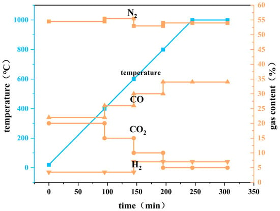
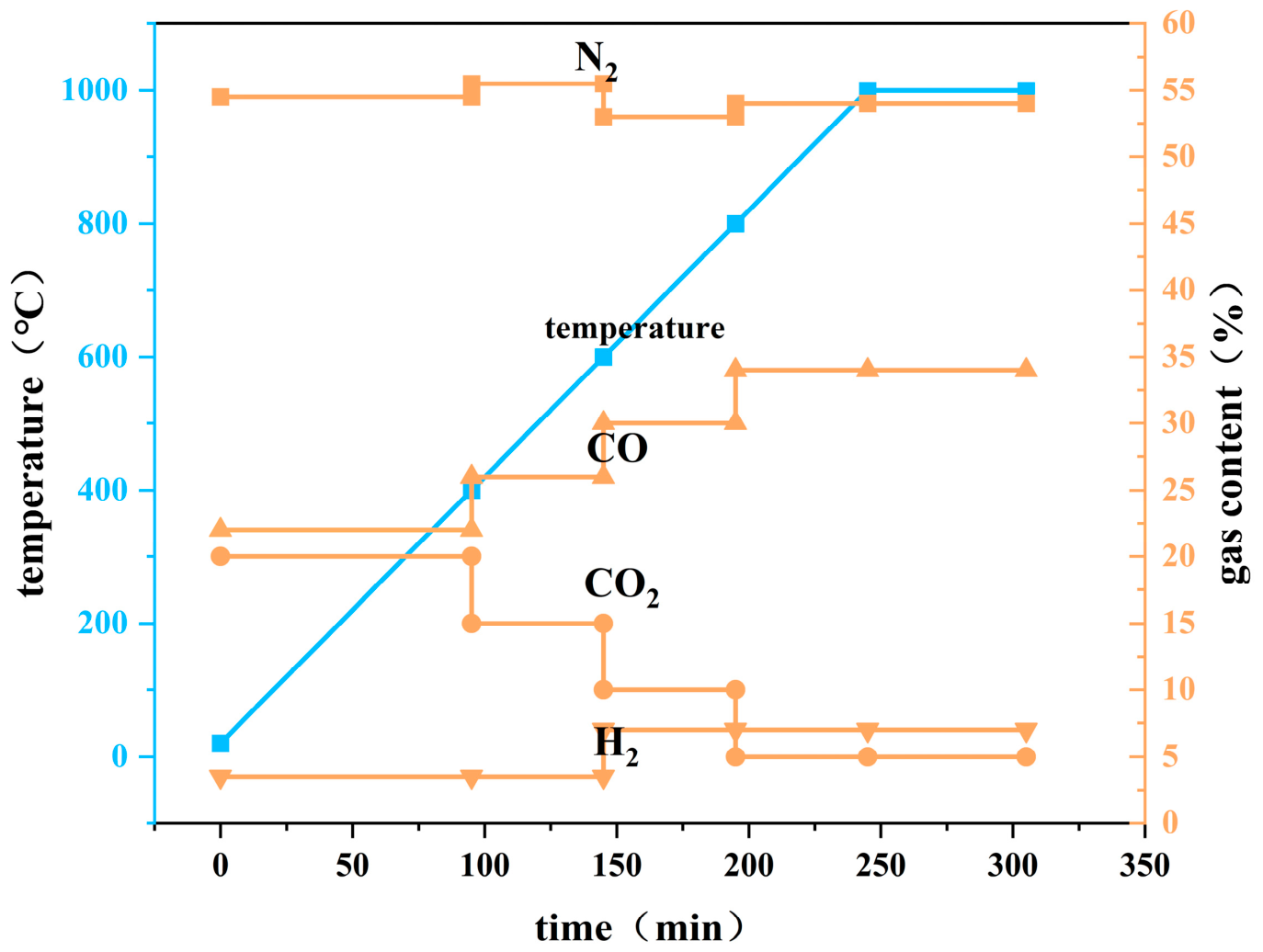
To investigate the reduction behavior of pellets with varying carbon addition ratios during their descent in the blast furnace, this study was based on operational data from an actual blast furnace. The research revealed that the temperature range in the lump zone was 400–1000 °C. Calculations from the blast furnace data indicated that the bosh gas composition was approximately (CO = 41.5%; H2 = 7.5%). Regarding residence time, previous studies have shown that coke and iron-bearing materials typically remain in the lump zone for about 3 to 5 h. On this basis, the gas schedule was developed to reproduce the progressive increase in the CO content and the CO/CO2 ratio with increasing depth (temperature) in the lump zone, bounded by typical upper-furnace gas compositions at 400 °C and approaching the measured bosh gas composition at 1000 °C; the resulting gas mixtures are listed below. The gas mixtures were switched stepwise at the boundary temperatures of the successive intervals, and the profiles in Figure 1 show the measured gradual transitions that resulted from the gas switching during each temperature interval. The total gas flow rate was 12 L/min, the sample charge was 500 g, and the furnace was operated at approximately atmospheric pressure.
Figure 1.
Heating regime for pellet reduction experiment.
Based on these conditions, the reduction experiment was conducted as follows: first, pre-reduction pellets (10.0–12.5 mm) were dried in an oven at 105 °C for 5 h to remove moisture. The reduction test was then performed in a vertical tube furnace following the heating profile shown in Figure 1. The temperature was increased from room temperature to 400 °C under a gas mixture of (22% CO, 20% CO2, 3.5% H2, 54.5% N2), then from 400 °C to 600 °C under (26% CO, 15% CO2, 3.5% H2, 55.5% N2), followed by heating to 800 °C under (30% CO, 10% CO2, 7% H2, 53% N2). Finally, the temperature was raised to 1000 °C under a reducing atmosphere (34% CO, 5% CO2, 7% H2, 54% N2), held isothermally for 1 h, and subsequently cooled to room temperature under N2 purging.
Subsequently, the reduced pellets were assessed using the weight loss method to determine their reduction degree.
The reduction degree of the iron ore was calculated using the following formula. The formula accounts for the initial FeO content through the term 0.11W1/(0.43W2), which corrects for the starting oxidation state of iron. The reduction degree of each fired pellet formulation was calculated using this complete formula. The FeO and total iron (TFe) contents of each fired pellet formulation are listed in Table 5 (determined by chemical titration and XRF analysis, respectively).
where:
M0: sample mass, g;
M1: instantaneous mass of the test sample immediately before the start of reduction, g;
M2: mass of the test sample after reduction, g;
W1: FeO content of the test sample before the test, expressed in mass percent;
W2: total iron (TFe) content of the test sample before the test, expressed in mass percent.
Table 5.
Main components of fired pellets.
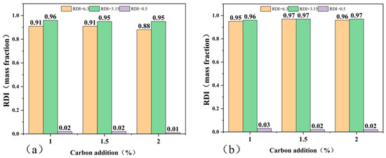
Additionally, the reduction degradation index (RDI) of the pellets was tested using a tumbler test performed after completion of the full reduction program described above. After reduction, the pellets were cooled under N2 and then placed in a standard laboratory tumbler (diameter 200 mm) and rotated at 20 rpm for 200 revolutions. The RDI was defined as the mass fraction of fines (−0.5 mm) generated after tumbling, normalized to the total sample mass; RDI+3.15 refers to the mass fraction retained on a 3.15 mm sieve. This test characterizes disintegration after the reduction program rather than low-temperature reduction disintegration.
where:
MD0: total mass of the sample after reduction;
MD1: mass of the fraction smaller than 0.5 mm after sieving;
MD2: mass of the fraction between 3.15 mm and 6.3 mm after sieving;
MD3: mass of the fraction larger than 6.3 mm after sieving.
The pellet volume was measured before and after reduction by the water displacement method, and the reduction swelling index (RSI) was calculated as follows:
where
V0: volume of the pellets before reduction
V1: volume of the pellets after reduction
3. Results and Discussion
3.1. Pellet Phase Changes
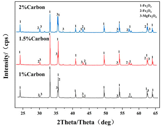
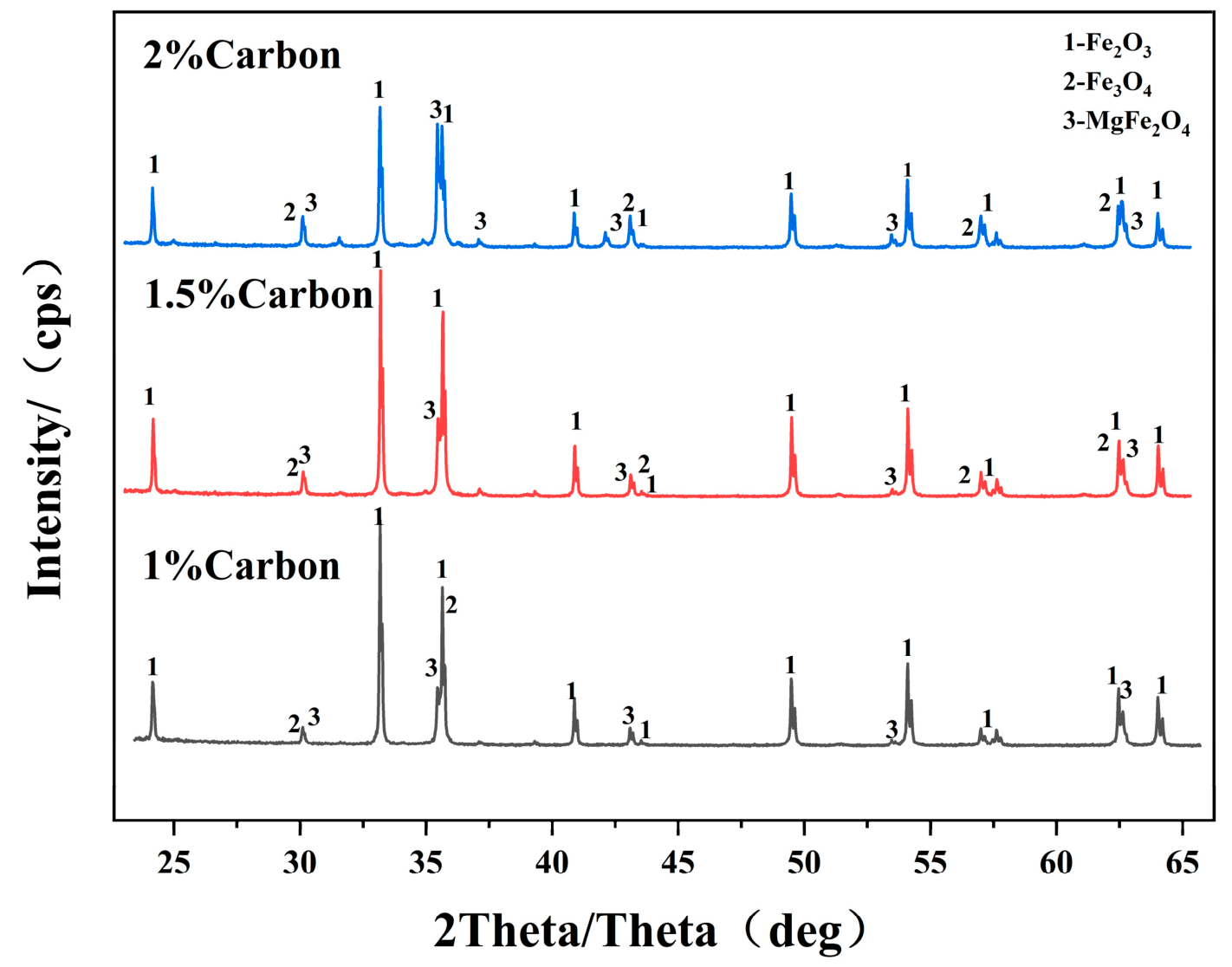
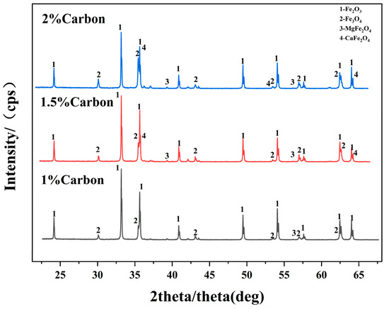
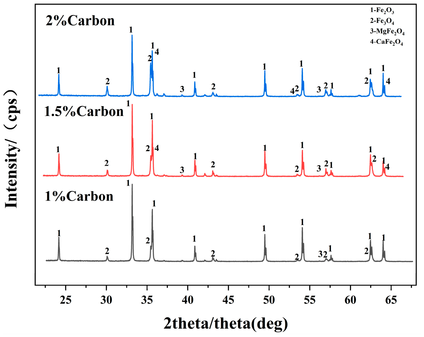
After roasting with added coke fines, the acidic pellets (Figure 2) are dominated by Fe2O3 as the main crystalline phase, with minor amounts of Fe3O4 and MgFe2O4. As the internal carbon addition increases from 1% to 2%, the relative intensities of the phases show no significant change, indicating that under low-basicity acidic conditions the system atmosphere ultimately becomes oxidizing after roasting; consolidation relies mainly on high-temperature recrystallization of Fe2O3, and the carbon content has a limited effect on phase composition. In the basic pellets (Figure 3), apart from iron oxides, a Ca-containing ferrite phase appears, and its type changes as the carbon addition increases: at 1% carbon, Fe2O3 predominates with a small amount of residual Fe3O4; at 1.5% carbon, CaFe2O4 begins to appear; at 2% carbon, CaFe2O4 forms as the bonding phase, and the Fe3O4 content also rises accordingly. Because coke fines generate CO, the coke reaction produces a locally reducing atmosphere that reduces the already formed Fe2O3 to Fe3O4, causing the Fe3O4 diffraction peaks to strengthen with increasing carbon addition; meanwhile, the high temperature promotes the conversion of CaO and Fe2O3 into the high-temperature-stable CaFe2O4. The core difference between the two lies in the fact that the introduction of CaO into the basic pellets forms a multi-component CaO–Fe2O3–MgO reaction system, and the consolidation mechanism shifts from the oxidation–recrystallization of Fe3O4 alone to consolidation by the calcium ferrite bonding phase, making the process window more sensitive to carbon addition. CaFe2O4 has a high melting point and is not prone to over-melting, so it is easier to strike a balance between strength and high-temperature metallurgical properties.
Figure 2.
XRD patterns of acidic pellets before reduction.
Figure 3.
XRD patterns of basic pellets before reduction.
3.2. Porosity and Compressive Strength
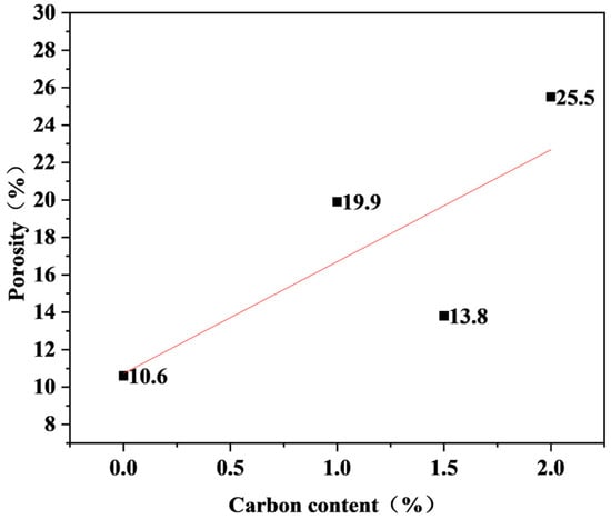
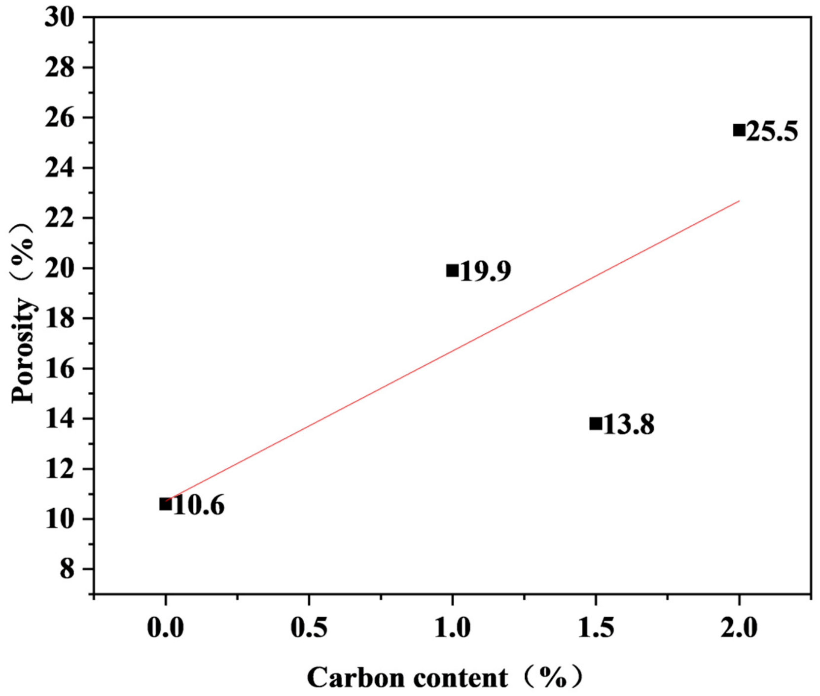
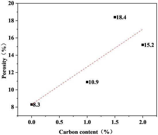
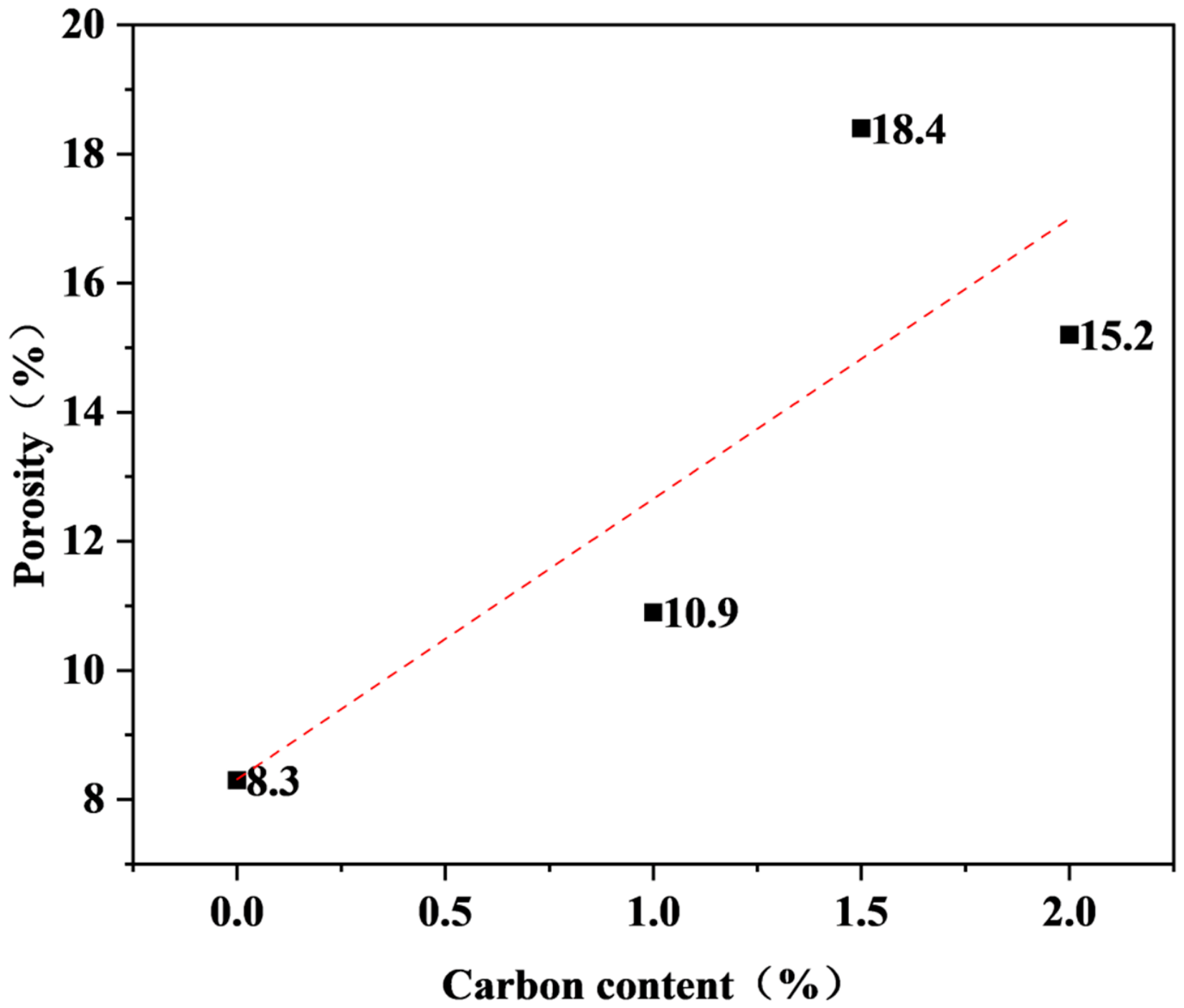
Figure 4 shows the variation in the basic pellet porosity with carbon addition. As shown in Figure 4, the porosity does not increase monotonically with carbon content: it rises from 10.6% (carbon-free) to 19.9% at 1% carbon addition, decreases to 13.8% at 1.5%, and then increases sharply to 25.5% at 2%. Similarly, Figure 5 shows that the porosity of the acidic pellets increases from 8.3% (carbon-free) to 10.9% at 1% carbon addition, reaches 18.4% at 1.5%, and then decreases to 15.2% at 2%. Under identical carbon content conditions, the porosity of the acidic pellets is generally lower than that of the basic pellets. Two main factors account for the overall porosity increase with carbon addition. First, during firing, carbon undergoes combustion reactions with oxygen, generating CO2 and CO; the escape of these gases from the pellets creates pores, and the volume of gas produced increases with the carbon content. Second, carbon participates in the reduction of iron oxides during firing, producing metallic iron and CO; since metallic iron occupies less volume than the iron oxides, the associated volumetric shrinkage further contributes to pore formation [22]. The non-monotonic porosity variations indicate that pore generation is superimposed on consolidation processes: at intermediate carbon additions, enhanced liquid-phase formation and sintering, particularly for the basic pellets with their higher CaO and MgO contents [23], can densify the structure and reduce porosity, whereas at higher carbon additions, the intensified gas generation dominates and increases porosity. Interestingly, between 1% and 1.5% carbon addition, the porosity of the basic pellets decreases (19.9% → 13.8%) while the reduction degree increases (64.9% → 70.3%) and the compressive strength decreases (2958 N → 1825 N). This apparent paradox indicates that total porosity alone cannot explain the observed property changes, and that the pore size distribution, pore connectivity, and phase composition must also be taken into account. The strength loss over this interval, despite the lower total porosity, suggests that factors other than porosity, such as the phase assemblage and the bonding between particles, govern the strength, while the continued improvement in reducibility may reflect improved pore connectivity rather than an increase in total porosity.
Figure 4.
Variation of basic pellet porosity with carbon addition content.
Figure 5.
Variation of acidic pellet porosity with carbon addition content.
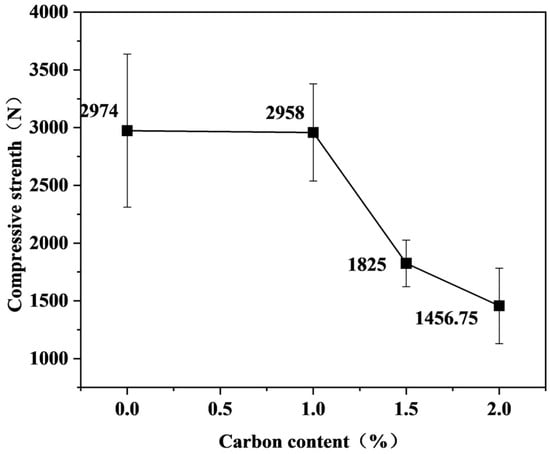
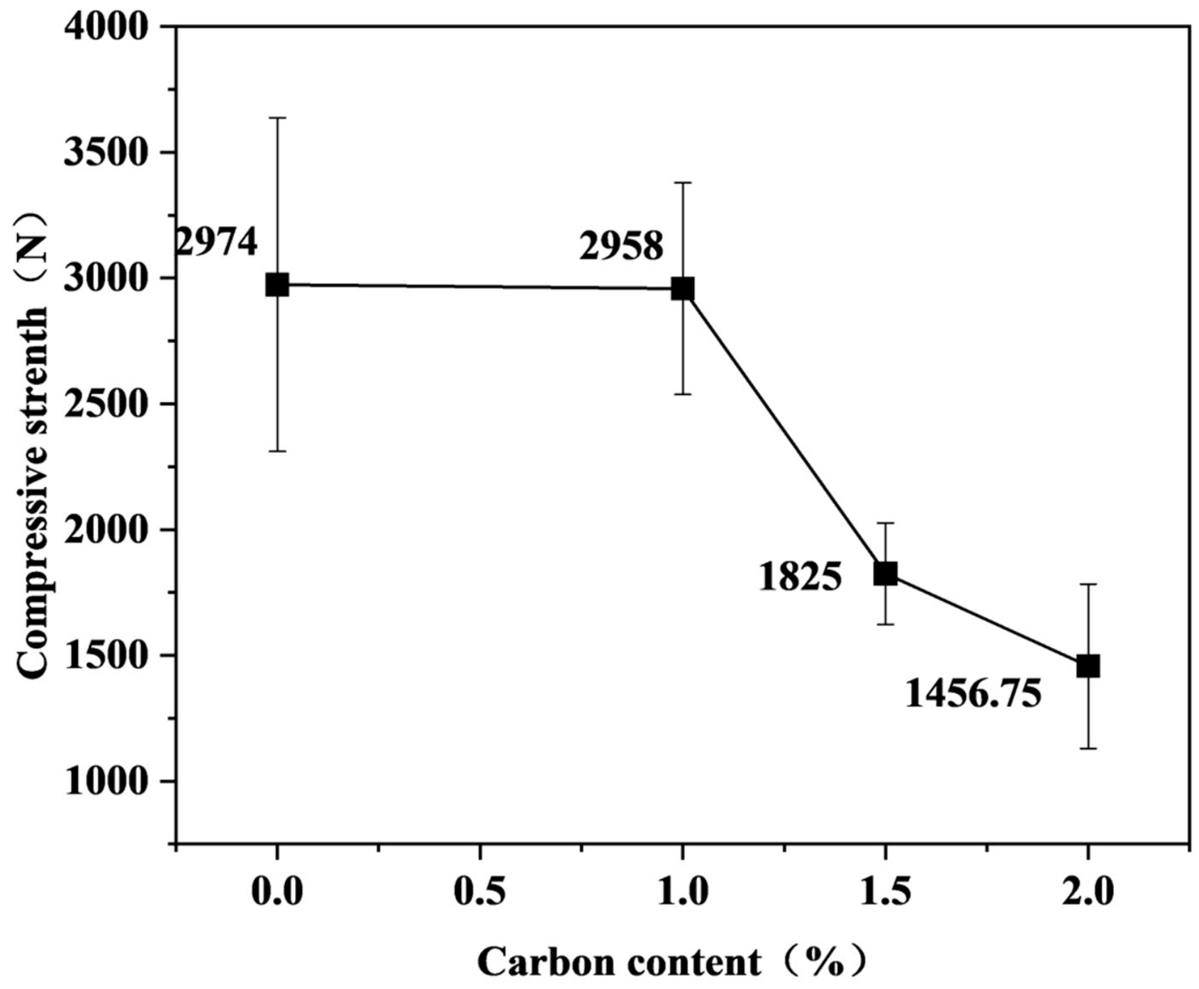
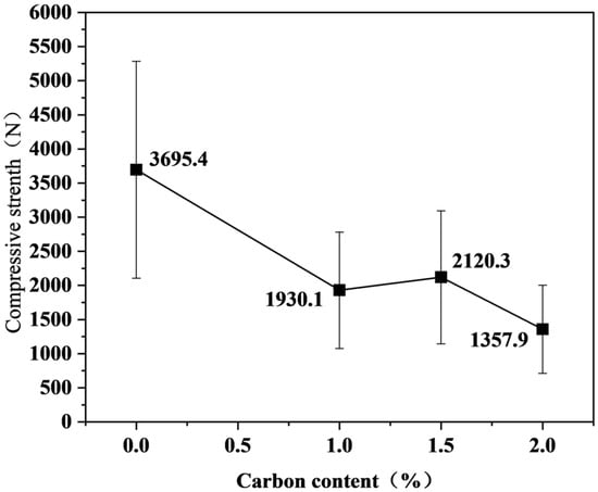
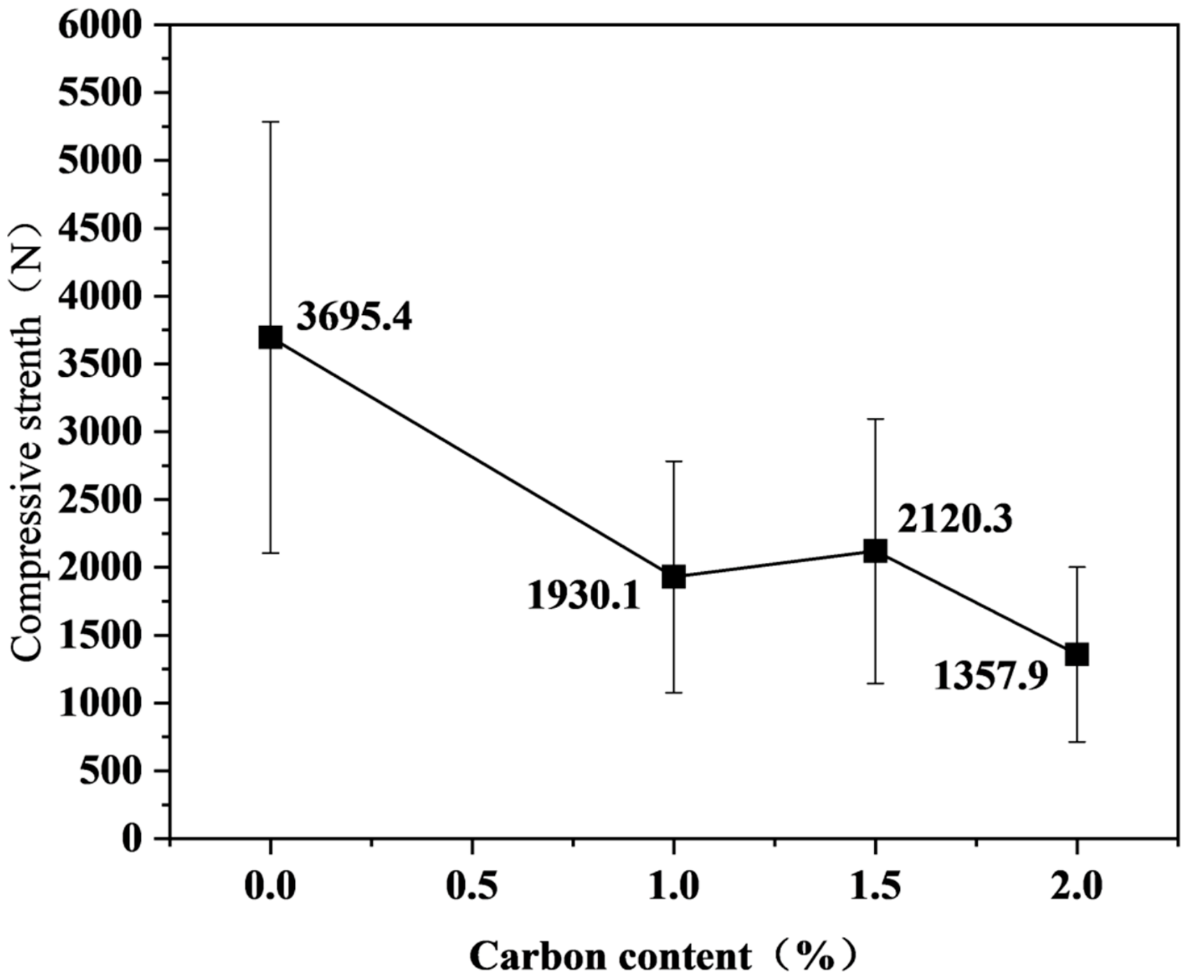
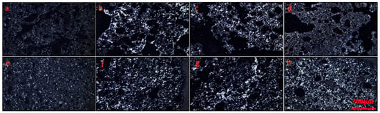
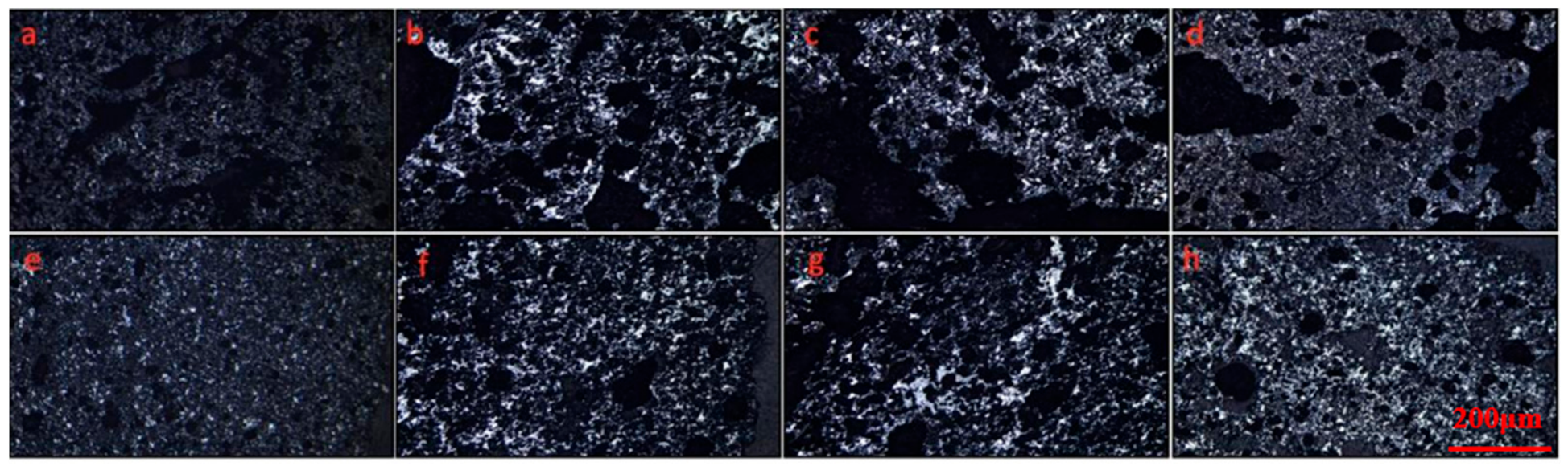
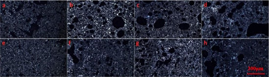
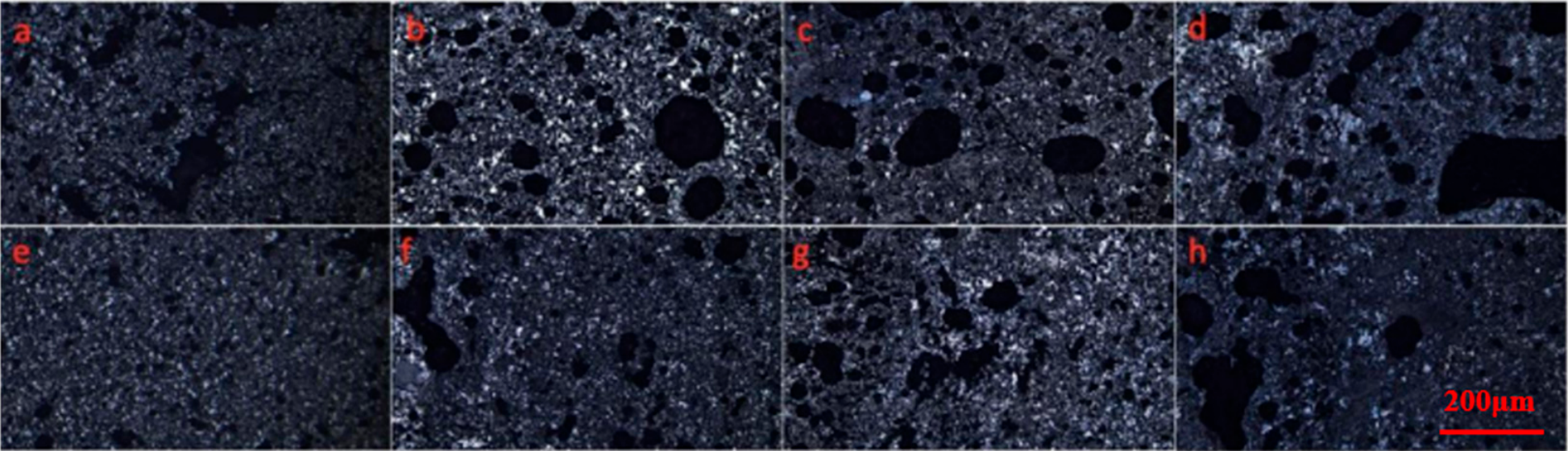
Figure 6 and Figure 7 show the variation in pellet compressive strength with carbon addition amount. A marked deterioration in compressive strength is observed for both pellet types with increasing carbon content. Acidic pellets demonstrate a 63.3% strength reduction (from 3695.4 N to 1357.9 N), while basic pellets show a 51.0% decline (from 2974 N to 1456.7 N). This mechanical degradation exhibits a strong negative correlation with porosity, indicating that increased porosity weakens the structural integrity of the pellets, thereby reducing their ability to withstand external forces. Figure 8 and Figure 9 show that as carbon content increases, the number of internal and external pores rises noticeably, and the proportion of large-diameter pores also increases. These pores compromise the structural integrity of the pellets, leading to a decline in compressive strength. Large-diameter pores make the pellets more prone to deformation or fracture under external forces, further reducing their compressive strength [24].
Figure 6.
Variation of basic pellet compressive strength with carbon addition amount.
Figure 7.
Variation of acidic pellet compressive strength with carbon addition amount.
Figure 8.
Pore structure of basic pellets: (a) Interior of carbon-free pellet (b) Interior of 1% carbon-added pellet (c) Interior of 1.5% carbon-added pellet (d) Interior of 2% carbon-added pellet (e) Surface of carbon-free pellet (f) Surface of 1% carbon-added pellet (g) Surface of 1.5% carbon-added pellet (h) Surface of 2% carbon-added pellet.
Figure 9.
Pore morphology of acidic pellets: (a) Cross-section of carbon-free pellet (b) Cross-section of 1% carbon-loaded pellet (c) Cross-section of 1.5% carbon-loaded pellet (d) Cross-section of 2% carbon-loaded pellet (e) Surface morphology of carbon-free pellet (f) Surface morphology of 1% carbon-loaded pellet (g) Surface morphology of 1.5% carbon-loaded pellet (h) Surface morphology of 2% carbon-loaded pellet.
For acidic pellets, compressive strength drops below the production requirement of 2000 N when the carbon content exceeds 1.5%. In contrast, basic pellets exhibit compressive strength below the required 2000 N when the carbon content exceeds 1%. This indicates that in actual production, carbon content must be strictly regulated to ensure that pellet compressive strength meets industrial standards.
3.3. Pellet Reduction Characteristics
Effect of Carbon Addition on Pellet Reduction Degree
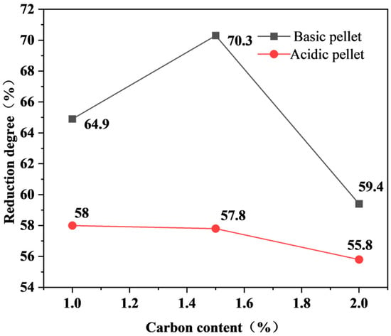
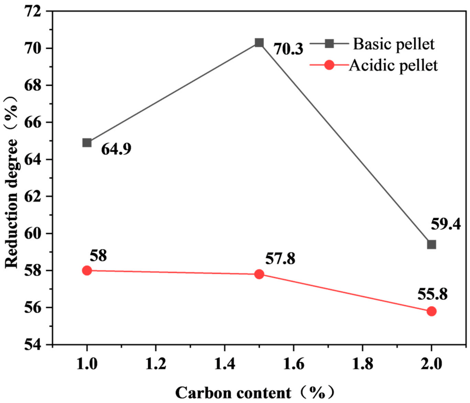
The variation in the reduction degree of basic pellets with carbon addition is shown in Figure 10. As the carbon content increases, the reduction degree of basic pellets first increases and then decreases. At a carbon addition of 1%, the reduction degree reaches 64.9%. As the carbon content further increases to approximately 1.5%, the reduction degree rapidly peaks at 70.3%. Beyond this point, additional carbon addition leads to a significant decrease in reduction degree, dropping to 59.4% at 2% carbon addition. This indicates the existence of an optimal carbon addition range that maximizes the reduction degree, while excessive or insufficient carbon addition adversely affects the reduction process.
Figure 10.
Variation of pellet reduction degree with carbon addition.
A similar trend is observed for acidic pellets, where excessive carbon addition also reduces the reduction degree. As shown in Figure 10, increasing the carbon content from 1% to 2% causes the reduction degree of acidic pellets to decline from 58% to 55.8%. These results indicate that carbon addition has a non-monotonic influence on the reducibility of basic pellets and a moderate adverse effect on that of acidic pellets; the appropriate carbon addition level must be balanced against the compressive strength and swelling requirements in practice.
The initial reducibility enhancement in the basic pellets (1–1.5% C) stems from carbon-induced porosity optimization. This open-pore architecture facilitates gas–solid interactions through an increased reactive surface area, thereby accelerating hematite reduction kinetics via enhanced CO(g) accessibility. Beyond 1.5% carbon addition, the reduction degree declines by 15.5% (relative). This decline is attributed primarily to the increased content of difficult-to-reduce phases formed during firing. As the carbon addition increases, the locally reducing atmosphere inside the pellets during firing stabilizes magnetite (Fe3O4) and magnesioferrite (MgFe2O4) (Figure 3) and may promote the formation of fayalite (Fe2SiO4) through the reaction of FeO with SiO2 in the gangue; compared with hematite, these phases are markedly more difficult to reduce [25,26]. In addition, the intensified gas generation at high carbon additions coarsens the pore structure (Figure 8 and Figure 9), and large voids are less effective than fine, connected pores in providing reactive surface area for gas–solid reduction, which further weakens the reduction kinetics [27]. It should be emphasized that these effects occur during the firing stage; the coke is largely consumed during induration, so the residual carbon available during the reduction test is limited, and its direct contribution to the reduction trends is expected to be minor.
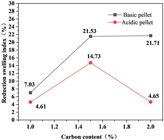
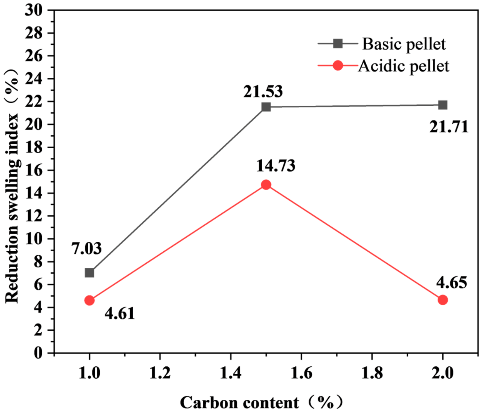
Figure 11 illustrates the changes in the reduction swelling index of basic and acidic pellets as carbon addition increases from 1% to 2%. With increasing carbon addition, the swelling index of basic pellets first rises to approximately 21.53%, then fluctuates slightly, while the swelling index of acidic pellets peaks at 14.73% with 1.5% carbon addition before gradually decreasing. Overall, the swelling index of basic pellets is generally higher than that of acidic pellets, and both types of pellets exhibit nonlinear trends in swelling index variation.
Figure 11.
Variation of pellet reduction swelling index with carbon addition content.
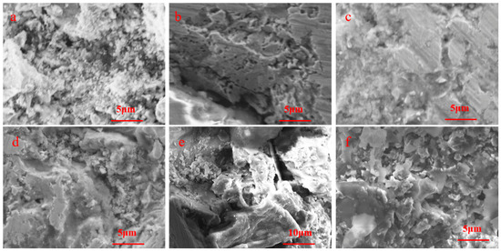
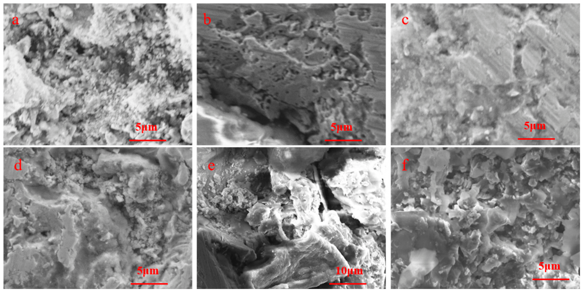
The effect of carbon addition on pellet microstructure is shown in Figure 12. Iron in the pellets primarily precipitates and accumulates in the form of iron whiskers and massive clusters. When FexO is reduced to Fe, some iron tends to accumulate at the edges of the original particles, forming iron whiskers. The excessive growth of these whiskers can loosen the pellet structure, leading to detrimental swelling [28,29]. In the SEM images, the elongated, needle-like protrusions growing from the edges of the original particles were identified as iron whiskers formed during the FeO → Fe reduction step, whereas the dense aggregates were identified as massive iron clusters.
Figure 12.
SEM images of reduced pellets: (a) basic pellet with 1% carbon addition; (b) basic pellet with 1.5% carbon addition; (c) basic pellet with 2% carbon addition; (d) acidic pellet with 1% carbon addition; (e) acidic pellet with 1.5% carbon addition; (f) acidic pellet with 2% carbon addition. Magnifications: 5000× for (a–d) and (f); 2300× for (e).
As illustrated in Figure 12a, the internal structure of basic pellets with 1% carbon addition shows iron predominantly precipitating as massive clusters, resulting in a denser pellet structure and correspondingly lower swelling indices. By contrast, Figure 12b,c demonstrate that as carbon addition increases to 1.5–2%, iron mainly precipitates as elongated whiskers, causing structural loosening and consequently increasing the reduction swelling index. It should be noted that the pellets with different carbon additions reached different final reduction degrees (Section Effect of Carbon Addition on Pellet Reduction Degree), which also influence the amount and morphology of the precipitated metallic iron; the comparison of the microstructures in Figure 12 is therefore qualitative. Within each pellet series, the sample exhibiting the most pronounced whisker development also exhibited the highest swelling index, indicating a qualitative correlation between whisker formation and swelling; nevertheless, whisker growth is regarded as one of the contributing factors to the swelling behavior rather than the sole mechanism.
Figure 12d–f present the microstructural evolution of acidic pellets. Figure 12d shows the microstructure of acidic pellets with 1% carbon addition, where iron aggregates primarily in massive form, yielding lower reduction swelling. At 1.5% carbon addition, Figure 12e shows the formation of elongated iron whiskers, enhancing pellet swelling. Interestingly, further carbon addition leads to the reappearance of massive iron clusters (Figure 12f), consequently reducing the swelling index again [30].
From the perspective of reducing swelling, acidic pellets maintain swelling indices below 20% regardless of carbon addition, while basic pellets should maintain carbon addition below 1.5% to control swelling.
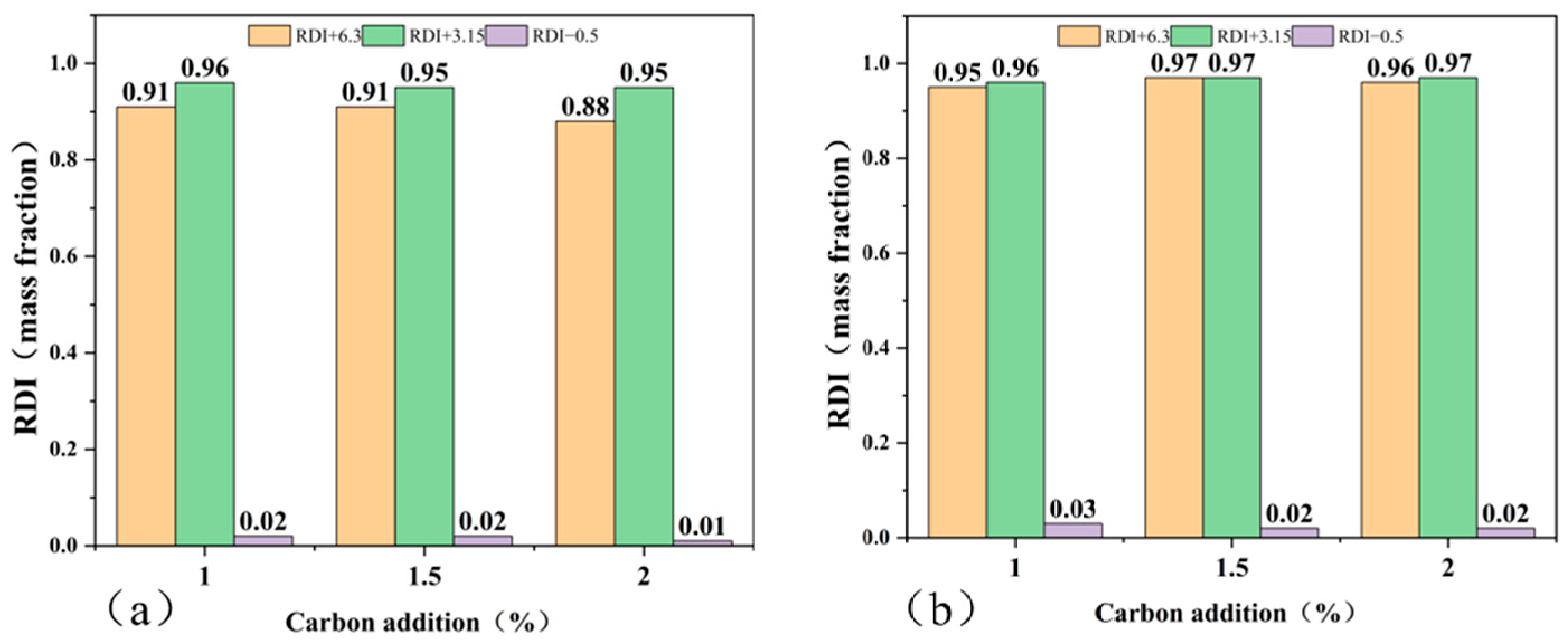
The variation in the pellet reduction degradation index (RDI) with carbon addition level is shown in Figure 13. For basic pellets, the RDI shows a slight increase with increasing carbon addition, while for acidic pellets, the RDI demonstrates a minor decrease as carbon addition rises. Overall, carbon addition appears to have a relatively minor effect on RDI for both acidic and basic pellets.
Figure 13.
Variation of reduction degradation index (RDI) for basic pellets (a) and acidic pellets (b) with carbon addition content.
4. Conclusions
The influence of carbon addition ratio on the compressive strength and reduction performance of oxidized pellets was studied in this work. The results demonstrate that carbon addition content significantly affects the porosity, compressive strength, reduction degree, and reduction swelling index of pellets. The main conclusions are as follows:
(1) With increasing carbon addition, both acidic and basic pellets exhibit substantial increases in porosity and decreases in compressive strength. For acidic pellets, porosity rises from 8.3% to 15.2%, while compressive strength declines from 3695.4 N to 1357.9 N. Basic pellets show a porosity increase from 10.6% to 25.5% and a compressive strength reduction from 2974 N to 1456.7 N.
(2) The reduction degree of basic pellets first increases and then decreases with carbon addition, reaching a maximum of 70.3% at 1.5% carbon addition. In contrast, acidic pellets show a gradual decline in reduction degree with increasing carbon addition, indicating that excessive carbon negatively affects the reduction process.
(3) The reduction swelling index of basic pellets increases with carbon addition, peaking at 21.7% with 2% carbon addition. Acidic pellets exhibit an initial increase followed by a decrease in swelling index, with a maximum of 14.7% at 1.5% carbon addition. These variations primarily result from differences in the formation and aggregation patterns of iron whiskers.
Author Contributions
Conceptualization, H.Z. and D.S.; methodology, X.F. and X.L.; validation, G.C. and G.W.; formal analysis, S.W. and D.S.; investigation, X.F. and M.K.; resources, G.C. and X.L.; data curation, S.W. and X.L.; writing—original draft preparation, D.S.; writing—review and editing, H.Z. and M.K.; project administration, G.W. and S.W.; funding acquisition, H.Z. and M.K. All authors have read and agreed to the published version of the manuscript.
Funding
This research was funded by the National Natural Science Foundation of China (Grant Number: 52674524), the Interdisciplinary Research Project of Young Teachers in University of Science and Technology Beijing (Grant Number: FRF-IDRY-24-017), and China Baowu Low Carbon Metallurgy Innovation Foundation (Grant Number: BWLCF202314).
Data Availability Statement
The original contributions presented in this study are included in the article. Further inquiries can be directed to the corresponding authors.
Conflicts of Interest
Authors Dawei Sun and Xiaobin Fan were employed by the company Shougang Jingtang United Iron and Steel Co., Ltd. The remaining authors declare that the research was conducted in the absence of any commercial or financial relationships that could be construed as a potential conflict of interest.
References
- Zhao, Z. Research on Key Process Parameters of Gas-Based Shaft Furnace Direct Reduction Based on Hydrogen Metallurgy. Master’s Thesis, Northeastern University, Boston, MA, USA, 2021. [Google Scholar]
- Mogale, A.; Das, S.K.; Singhai, M.; Chavhan, V.; Hazra, S. Evaluation of Quality Parameters and Mineralogy of Iron Ore Pellets with Added Mill Scale. J. Sustain. Metall. 2024, 10, 2311–2324. [Google Scholar] [CrossRef] [Scilit]
- Tian, T.; Shi, X.; Cai, S.; Zhang, Y.; Xing, H.; Li, J. Pore Structure Characteristics of Magnesian Fluxed Pellets. Iron Steel 2016, 51, 10–14. [Google Scholar]
- Li, Z.; Wang, Y.; Chai, Y.; Wang, Y.; Song, X. Effect of Bentonite on the Strength of Green and Fired Pellets Made from Bayan Obo Iron Concentrate. China Metall. 2021, 31, 19. [Google Scholar]
- Avula, L.S.B.R.; Sahoo, S.K.; Kumar, M. Comparative Study on Reduction Behaviors of Low- and High-Grade Fired Hematite Iron Ore Pellets in Coal. Ironmak. Steelmak. 2024, 51, 1121–1130. [Google Scholar] [CrossRef] [Scilit]
- Luo, G.; Peng, Z.; Gao, K.; Fan, W.; Tian, R.; Yi, L.; Rao, M. Preparation of Metallized Pellets for Steelmaking by Hydrogen Cooling Reduction with Different Cooling Rates. Materials 2024, 17, 4362. [Google Scholar] [CrossRef] [Scilit] [PubMed]
- Perrone, A.; Cavalier, P.; Sadeghi, B.; Dijon, L.; Laska, A.; Koszelow, D. Carburization Behavior of High-Grade Pellets After Direct Reduction in Pure Hydrogen. J. Sustain. Metall. 2024, 10, 1991–2008. [Google Scholar] [CrossRef] [Scilit]
- Bersenev, I.S.; Pokolenko, S.I.; Sabirov, E.R.; Spirin, N.A.; Borisenko, A.V.; Kurochkin, A.R. Influence of the Iron Ore Pellets Macrostructure on Their Strength. Steel Transl. 2024, 53, 1018–1022. [Google Scholar] [CrossRef] [Scilit]
- Long, W.; Zhou, H.; Sun, D.; Wu, J.; Kou, M.; Wu, S. Characterization of Pellet Compressive Strength Based on Industrial CT Micro-Pore Structure. China Metall. 2024, 34, 82. [Google Scholar]
- Lan, D.; Zhang, J.; Li, Z.; Wang, Y.; Xu, C.; Qiao, H.; Li, Z.; Liu, Z. Three-Dimensional Pore Structure Characterization and Performance Analysis of Pellets Based on Industrial CT. Sinter. Pelletizing 2023, 48, 99. [Google Scholar]
- Wang, X.; Jin, Y. Prospects for High-Proportion Pellet Usage in Blast Furnaces Under the “Dual Carbon” Background. J. Chin. J. Process Eng. 2022, 222, 1379. [Google Scholar]
- Hegede, V.S.; Ge, H. Research on Fluxed Pellets with Increased Internal Coke Powder Addition. Sinter. Pelletizing 1992, 2, 58. [Google Scholar]
- Yi, L.; Pan, J.; Tian, H.; Zhu, D.; Jiang, L.; Li, M. Effect of Internal Carbon Addition on the Metallurgical Properties of Oxidized Pellets. Sinter. Pelletizing 2020, 45, 28. [Google Scholar]
- Yu, H.; Wang, Y.; Gao, Y.; Ma, W.; Cui, J. Industrial Practice of Internal Carbon Addition at Ansteel’s Dagushan Pellet Plant. Liaoning Chem. Ind. 2021, 50, 529. [Google Scholar]
- Wang, X.; Han, F.; Hu, Q.; Xia, Z.; Chen, D. Effect of Internal Carbon Addition on the reduction swelling index of Double-Layer Pellets. J. Anhui Univ. Technol. Nat. Sci. 2013, 30, 107. [Google Scholar]
- Zhang, J.; Liu, Z.; Jiao, K.; Xu, R.; Li, K.; Wang, Z.; Wang, C.; Wang, Y.; Zhang, L. Advances in Ironmaking Technologies and Fundamental Theoretical Research. Chin. J. Eng. 2021, 43, 1630. [Google Scholar]
- Wen, B.; Fan, Z.; Li, J.; Yang, J.; Liu, D. A Novel Approach to Enhance Decrepitation Temperature and Reducibility of Ultrafine Iron Ore Concentrate Pellets. J. Iron. Steel Res. Int. 2024, 31, 2622–2632. [Google Scholar] [CrossRef] [Scilit]
- Ueda, S.; Watanabe, K.; Yanagiya, K.; Inoue, R.; Ariyama, T. Improvement of Reactivity of Carbon-Iron Ore Composite with Biomass Char for Blast Furnace. ISIJ Int. 2009, 49, 1505–1512. [Google Scholar] [CrossRef] [Scilit]
- Rashid, R.Z.A.; Salleh, H.M.; Ani, M.H.; Yunus, N.A.; Akiyama, T.; Purwanto, H. Reduction of Low Grade Iron Ore Pellet Using Palm Kernel Shell. Renew. Energ. 2014, 63, 617–623. [Google Scholar] [CrossRef] [Scilit]
- Sahu, S.N.; Biswal, S.K. Alleviating Dependency on Fossil Fuel by Using Cow-Dung During Iron Ore Pelletization; Assessment of Pellet Physical and Metallurgical Properties. Powder Technol. 2020, 381, 401. [Google Scholar] [CrossRef] [Scilit]
- Pereira, P.M.; Bagatini, M.C. Influence of carbon content on mechanical properties of iron ore pellets. Technol. Metal. Mater. Miner. 2018, 15, 481–487. [Google Scholar] [CrossRef] [Scilit]
- Yi, L.; Huang, Z.; Jiang, T.; Wang, L.; Qi, T. Swelling Behavior of Iron Ore Pellet Reduced by H2–CO Mixtures. Powder Technol. 2015, 269, 290–295. [Google Scholar] [CrossRef] [Scilit]
- Tao, J.J.; Di, L.Q.; Dong, X.X.; Ke, M.; Jian, Z. Investigations on Compressive Strength and Microstructure of High-Basicity Iron Ore Pellets. JOM-US 2023, 75, 2525–2534. [Google Scholar] [CrossRef] [Scilit]
- Wang, R.; Zhang, J.; Steinar, S.; Tore, R.; Wang, C.; Qing, G.; Cheng, Z.; Liu, Z.; Liu, X.; Wang, X.; et al. Study on the Effect of Adding Sibelco Olivine on Pellet Properties. In Proceedings of the 11th China Iron & Steel Annual Conference; The Chinese Society for Metals: Beijing, China, 2017; pp. 431–437. [Google Scholar]
- You, F. Study on the Reduction Mechanism of Internal Carbon-Containing Pellets Made from Bayan Obo Iron Concentrate. Master’s Thesis, Inner Mongolia University of Science and Technology, Baotou, China, 2014. [Google Scholar]
- Zhang, S.; Zong, Y.; Huang, Y.; Gui, X.; Lei, D.; Zhang, J.; Gan, X.; Wang, Z.; Zhang, S.; Lu, P. Investigation of Basicity on Compressive Strength and Oxidation Induration Mechanism of Vanadium–Titanium Magnetite Pellets. Steel Res. Int. 2024, 95, 2400461. [Google Scholar] [CrossRef] [Scilit]
- Hesham, A.; Kumar, T.K.S.; Johanna, A.; Bo, B. Effect of Carbon Concentration and Carbon Bonding Type on the Melting Characteristics of Hydrogen-Reduced Iron Ore Pellets. J. Mater. Res. Technol. 2022, 21, 1760. [Google Scholar] [CrossRef] [Scilit]
- Li, W.; Fu, G.; Chu, C.; Zhu, M. Effect of Reducing Conditions on Swelling Behavior and Mechanism of Hongge Vanadium Titanomagnetite-Oxidized Pellet with Hydrogen-Rich Gases. Int. J. Hydrogen Energy 2017, 42, 24667. [Google Scholar] [CrossRef] [Scilit]
- Guo, Y.; Liu, K.; Liu, Y.; Chen, F.; Wang, S.; Zheng, F. Research Progress on the Reduction Swelling Mechanism and Influencing Factors of Iron Ore Pellets. Iron Steel 2021, 56, 9. [Google Scholar]
- Long, H.; An, J.; Li, X.; Wu, T.; Lei, J. Mechanism Analysis of Effect of MgO on Reduction Swelling Behaviour of Iron Pellets in CO/H2 Atmosphere Based on First-Principles Calculations. J. Iron Steel Res. Int. 2024, 32, 73–84. [Google Scholar] [CrossRef] [Scilit]

Disclaimer/Publisher’s Note: The statements, opinions and data contained in all publications are solely those of the individual author(s) and contributor(s) and not of MDPI and/or the editor(s). MDPI and/or the editor(s) disclaim responsibility for any injury to people or property resulting from any ideas, methods, instructions or products referred to in the content. |
© 2026 by the authors. Licensee MDPI, Basel, Switzerland. This article is an open access article distributed under the terms and conditions of the Creative Commons Attribution (CC BY) license.