


Abstract
The combined damage induced by the nitrate molten salt corrosion and cyclic loading at elevated temperatures is an important damage issue for the reliable operation of concentrated solar power (CSP) plants. In previous works, the effect of the molten salt pre-corrosion on the fatigue behavior of 347H stainless steel remains insufficiently understood. Based on this, the present work investigated the corrosion behavior of 347H stainless steel in nitrate molten salts at 565 °C, with particular attention to chloride impurities. The effects of pre-corrosion on cyclic deformation characteristics, fatigue life, and failure mechanisms were discussed. The results indicated that the oxide-scale growth follows approximately parabolic kinetics in chloride-free salt, whereas chloride-containing salt exhibits sub-parabolic growth with a lower kinetic exponent. Chloride addition produces a thicker and less stable oxide scale characterized by cracking, spallation, and chromium depletion. The pre-corrosion does not alter the cyclic hardening characteristic of 347H stainless steel but significantly reduces its fatigue life. The corrosion-induced damage morphology also changes the subsequent fatigue crack initiation behavior. The relatively uniform oxidation promotes crack initiation at the oxide layer-substrate interface, whereas chloride-induced scale degradation introduces more severe local damage and accelerates crack initiation and propagation.
1. Introduction
Recently, the integration of CSP plants with thermal energy storage (TES) has emerged as a promising renewable energy utilization technology [1]. The high-temperature nitrate molten salt storage tank serves as a critical thermal energy storage component in CSP plants [2], and 347H stainless steel is selected as the structural material of the storage tank. During service, this component is subjected to a high temperature (565 °C) and nitrate molten salt corrosion environment [3,4]. Meanwhile, this component experiences load fluctuations caused by the frequent rise and fall of the liquid level. It can be expected that the combined damage induced by the nitrate molten salt corrosion and cyclic loading at elevated temperatures is an important failure mode, which accelerates the fatigue failure of the component [5]. Therefore, it is necessary to discuss the molten salt corrosion behavior and its effect on the fatigue behavior of 347H stainless steel for the long-term safe service of molten salt storage tanks. It should be stated that the pre-corrosion fatigue of 347H stainless steel is the focus of the present work, given the complexity involved in the direct coupling of the corrosion and fatigue damage.
In the past decades, many works have been reported on the corrosion behavior of structural materials in high-temperature nitrate molten salts. Some typical works are provided below. Baraka et al. [6] investigated the corrosion behavior of a low-carbon steel in NaNO3-KNO3 environment at 250–450 °C. They found that the corrosion process of the low-carbon steel followed a parabolic law, with the formation of a passive layer mainly composed of Fe3O4. Fernandez and Cabeza [7] reviewed the corrosion mechanism of metallic materials (e.g., austenitic stainless steels and carbon steels) in nitrate molten salt environment, suggesting that the driving force of the corrosion process was the reduction of to and O2−. They also reported that the chloride impurities exacerbated the corrosion of structural materials by promoting Cr dissolution and degrading the protective oxide layer. Cheng et al. [8] and Soleimani et al. [9] analyzed the corrosion behavior of alloys with different Cr contents in nitrate molten salts. They concluded that the high-chromium materials exhibited better corrosion resistance due to the formation of a protective oxide layer, whereas the oxide layers formed on the low-chromium materials were non-protective. Zhang et al. [10] studied the dynamic corrosion behavior of structural materials, and performed the microscopic characterization of the oxide layer using scanning electron microscopy (SEM), energy-dispersive X-ray spectroscopy (EDS), and X-ray diffraction (XRD). They found that high flow velocity and elevated temperature accelerated the corrosion process of the materials, and the structure and stability of the oxide layer played a key role in the corrosion resistance. Some studies [11,12,13] also demonstrated that the formation of the protective spinel structures (e.g., (K, Na)CrO4) or dual oxide layers (with a loose outer layer and a dense inner layer) could effectively reduce the corrosion rates. Liu et al. [14] investigated the early-stage corrosion characteristics of the molten nitrate salt–oxide–metal interface, revealing that the tensile stress between the inner Cr-rich oxide layer and the porous outer Na/Fe-rich oxide layer was correlated with the spallation of the outer layer. Meanwhile, the addition of specific additives changed the corrosion rate of the materials. Wang et al. [15] studied the corrosion of SS347 and GH3539 in molten solar salt with chloride and sulfate additions, showing that chlorides create an oxidation-chlorination environment that causes separation and spallation of the oxide scale from the stainless steel, thereby accelerating corrosion. In summary, although the corrosion behaviors of the structural materials in nitrate molten salts have been widely investigated, systematic studies on the long-term corrosion kinetics of 347H stainless steel (2400 h) in chloride-containing nitrate molten salt remain limited. Therefore, this work provides a comprehensive investigation on the corrosion behavior of 347H stainless steel, focusing on the evolution of oxide layers, corrosion kinetics, and the role of chloride impurities in the corrosion at elevated temperatures.
Regarding the pre-corrosion effect on the fatigue behavior of structural materials, the current works are mainly limited to the fatigue behavior in air environment at elevated temperatures [16]. For example, Suresh et al. [17] and Mariappan et al. [18] investigated the fatigue and tensile behaviors of 316LN stainless steel. The former revealed the local deformation mechanisms in a welded joint under thermomechanical fatigue loading, while the latter employed the Voce and Ludwigson equations to describe the effect of prior fatigue damage on the high-temperature tensile flow behavior. They pointed out that the dynamic strain aging (DSA) significantly increased the work hardening at high temperatures, and the peak stress increased first and then decreased, indicating a cyclic hardening feature. Wang et al. [19] reported the fatigue behavior of Fe-25Cr-20Ni austenitic stainless steel using SEM, electron backscatter diffraction (EBSD), and transmission electron microscopy (TEM) characterizations. Their results demonstrated that the gradient nanostructured layer inhibited the surface crack initiation and retarded the crack propagation in the high-cycle fatigue regime. Zhang et al. [20] discussed the tensile and fatigue deformation behaviors of laser powder bed fused (LPBF) 304L stainless steel using microstructural analysis techniques, including SEM, EBSD, TEM, XRD, and thermal imaging. The results presented that the LPBF-fabricated specimens possessed cellular substructures with high dislocation density, elemental segregation, and nano-inclusions. These cellular substructures, along with the associated α′ martensitic transformation, were the key mechanisms responsible for the excellent fatigue performance in LPBF 304L stainless steel. Zeng and Yuan [21] studied the mechanical behavior and fatigue performance of 06Cr19Ni10 metastable austenitic stainless steel using in-situ ferrite content measurements on pre-strained specimens. Their results showed that the plastic strain (cold hardening) improved the fatigue resistance in the high-cycle fatigue regime, while the fatigue limit was almost independent of the martensitic content; the martensitic transformation increased the fatigue property in the finite life regime, whereas severe plastic deformation degraded the fatigue performance in the low-cycle fatigue regime. Nitzsche et al. [22] analyzed the quasi-static tensile and fatigue behaviors of a Cu-alloyed metastable austenitic stainless steel using microstructural characterization methods such as SEM, EBSD, and magnetic measurements. Their results indicated that the fine-grained material produced by rotary swaging and reversion annealing exhibited the highest fatigue life, while the as-cast material had the shortest fatigue life due to its coarse grain size and lowest yield strength. Li et al. [23] and Che et al. [24] discussed the low-cycle fatigue behavior of austenitic stainless steel by combining EBSD characterization with surface replication or crystal plasticity modeling. The results indicated that the non-uniform distributions of grain size, orientation, and local misorientation induced stress concentration, which further affected crack initiation and mesoscale damage evolution.
Compared with the fatigue behavior in air environment, limited works on pre-corrosion effect on the fatigue behavior of structural materials have been conducted. For instance, Yadav et al. [25] reported the effect of pre-corrosion on the crack initiation behavior of friction stir welded AA2024-T3 aluminum alloy joints under fatigue conditions. They found that the pre-corrosion-induced corrosion pits served as preferred sites for fatigue crack initiation. The high-cycle fatigue endurance limit of the material decreased from 70 MPa to 50 MPa (strain ratio R = 0.1), and the low-cycle fatigue life was also reduced. Shen et al. [26] studied the effect of pre-corrosion on the low-cycle fatigue performance of high-N high-Mn steel. The results illustrated that with the increasing pre-corrosion time, the size and number of the corrosion pits increased, and the maximum stress concentration occurred at the bottom of the pit, leading to a significant reduction in fatigue life. The microstructure inside the corrosion pits featured a high density of nanotwins and stacking faults. Pradhan et al. [27] investigated the effect of pre-hot corrosion on the high-cycle fatigue behavior of superalloy IN718 at 600 °C. They concluded that after the pre-corrosion, the corrosion pits were observed on the specimen surface, and the harmful elements such as chlorine and sulfur penetrated into the pits. The fatigue cracks initiated at the bottom of the corrosion pits and propagated in a transgranular mode, with a faster growth rate. Shi et al. [28] studied the hot salt corrosion fatigue behavior of TC11 titanium alloy at 500 °C. The results displayed that the pre-corrosion led to the formation of the surface corrosion pits, with chlorine elements penetrating into the grain boundaries and forming TiH hydrides. The fatigue life was reduced by more than 99% for the salt deposition higher than 1 mg/cm2. Meanwhile, the stress concentration caused by the corrosion pits accelerated the fatigue crack initiation, while the hydrogen and hydrides promoted the crack propagation. Chen et al. [29] studied the effects of pre-deformation (i.e., pre-tension and pre-torsion) and pre-corrosion in 3.5% NaCl solution on the multiaxial fatigue performance of 2024-T4 aluminum alloy. They found that the synergistic effect of pre-deformation and pre-corrosion was more pronounced than that of either single damage type. The pre-deformation increased the dislocation density and the anodic dissolution rate, thereby exacerbating the formation of corrosion pits and accelerating the degradation of mechanical properties.
Despite extensive studies on the corrosion of austenitic stainless steels in nitrate molten salt and their fatigue behavior, the relationship between corrosion damage of 347H stainless steel in nitrate molten salt and subsequent fatigue degradation remains insufficiently understood. In particular, the differences between chloride-free and chloride-containing environments in terms of corrosion kinetics, oxide-scale integrity, and their subsequent effects on fatigue crack initiation have not been systematically clarified. This issue is relevant to the long-term integrity and life management of molten salt thermal storage components, because environmental degradation may interact with cyclic loading during service. Therefore, this work investigates the corrosion kinetics, surface damage evolution, and strain-controlled fatigue behavior of 347H stainless steel after pre-corrosion at 565 °C, aiming to describe the relationship between corrosion-induced damage and fatigue degradation.
The framework of this work is arranged as follows. Section 2 presents the materials and specimens for the static corrosion tests and pre-corrosion fatigue tests. The results and discussion are given in Section 3, including the corrosion kinetics, corrosion surface morphology, corrosion mechanisms, fatigue deformation behavior and failure life, and fatigue fracture surface morphology of 347H stainless steel. The conclusions drawn from this work are summarized in Section 4.
2. Experimental Configurations
2.1. Material
The material used in this study is 347H stainless steel, which serves as the structural material for high-temperature molten salt storage tanks in CSP plants. This material, stabilized with niobium (Nb), exhibits excellent corrosion resistance and mechanical properties at elevated temperature. The chemical composition of 347H stainless steel is presented in Table 1.
Table 1.
Chemical compositions of 347H stainless steel (wt%).
The corrosive environment selected in this study is the binary nitrate molten salt used as the thermal energy storage medium in CSP plants. To analyze the influence of chloride impurities, two types of molten salt corrosive environments were considered in this study. The first corrosive environment is a binary nitrate salt (denoted as SS) with a composition of 40 wt% KNO3 + 60 wt% NaNO3. The second corrosive environment is a binary nitrate salt containing 3.5 wt% NaCl (denoted as SS_3.5), prepared by mixing NaCl (purity ≥ 99.5%) with the nitrate molten salt in a certain weight ratio. The mixed molten salt was placed in a corundum crucible and stirred evenly for complete homogenization. After preparation, the powdered salt was placed in a mixer to ensure complete mixing of the nitrate salt and the added NaCl. The mixed nitrate salt was then placed in a vacuum drying oven at 120 °C for more than 24 h to remove moisture. After cooling, it was sealed and stored at room temperature for subsequent use. The chemical compositions of the two molten salt groups are shown in Table 2.
Table 2.
Chemical compositions of two different molten salts.
2.2. Static Corrosion Test
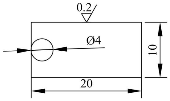
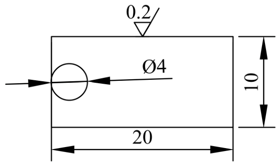
The dimensions of the corrosion specimen are presented in Figure 1. The specimen is of the coupon type, with dimensions of 20 mm × 10 mm × 2 mm. Prior to the test, the specimen surface was sequentially ground using 400#, 1200#, and 2000# grit sandpaper to achieve a uniform finish, followed by polishing in a single direction using 1 μm diamond polishing agent until a surface roughness Ra ≤ 0.2 was obtained. Finally, the coupon specimens were ultrasonically cleaned in anhydrous ethanol for 5 min, and then dried with cold air.
Figure 1.
Dimensions of coupon specimens for static corrosion tests.
Considering the service temperature of molten salt storage tanks, the test temperature in static corrosion was set as 565 °C. Two crucibles were placed in a muffle furnace and pre-melted at 300 °C for 12 h for a uniform distribution of the molten salt. Then, eighteen coupon specimens and four fatigue specimens of 347H stainless steel were vertically placed in each crucible, with a certain distance maintained between the specimens to ensure that each specimen was fully immersed in the molten salt. The temperature was increased to 565 °C at a rate of 5 °C/min, and then the static corrosion test began. For each salt condition, one specimen was taken out after each corrosion time (see Table 3). Cross-sectional oxide thickness was measured on specimens at ten selected corrosion times (1, 20, 120, 336, 552, 744, 960, 1320, 1752, and 2400 h). The resulting thickness and growth-rate data are presented and discussed in Section 3.1. When the specimens were cooled to room temperature, they were cleaned with deionized water to eliminate the residual molten salt from the surface. In addition, all fatigue specimens were removed after the corrosion time of 2400 h.
Table 3.
Test duration time for static corrosion.
After the static corrosion tests, the surface micromorphology of the 347H stainless steel in the SS and SS_3.5 environments was observed using SEM (model S-3400N, Hitachi High-Tech Corporation, Tokyo, Japan). The elemental composition of the surface oxide layer was analyzed by EDS, and the phase constituents of the surface corrosion products were identified by grazing-incidence X-ray diffraction (GIXRD, model Smartlab 3 kW, Rigaku Corporation, Tokyo, Japan). Cross-sectional specimens were then prepared from the coupons for thickness measurement. Considering that the corrosion products were relatively fragile and prone to spalling during the cross-section preparation, the coupon specimens were protected by nickel electroplating prior to mounting. The plating followed the standard practice for preparation of and electroplating on stainless steel (ASTM B254 [30]) and included degreasing, nickel striking, and bright nickel plating; the plated coupons were then metallographically mounted. The detailed process is not repeated herein.
The oxide layer thickness was measured by SEM on the mounted cross-sections, and the average of multiple measurements at different locations was taken as the oxide layer thickness of each specimen. Elemental distribution analysis was performed in conjunction with EDS (model APOLLO X, EDAX Inc. (AMETEK), Mahwah, NJ, USA) line scan results. To evaluate the oxidation kinetics, the average oxide scale growth rate (voxide) was estimated using Equation (1). It should be noted that voxide represents the thickening rate of the oxide products rather than the actual metal loss penetration rate, because the conversion from oxide-scale thickness to metal-loss depth was not performed.
where, t is the corrosion time; d is the measured oxide layer thickness.
2.3. Pre-Corrosion Fatigue Test
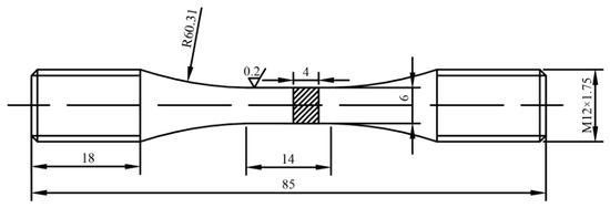
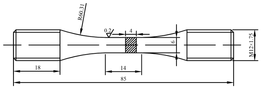
The dimensions of the fatigue specimen are shown in Figure 2. The gauge length is 14 mm, with the cross section of 6 mm × 4 mm. After machining, the specimens were polished for a surface roughness of Ra ≤ 0.2. Finally, the fatigue specimens were ultrasonically cleaned in anhydrous ethanol for 5 min and dried with cold air.
Figure 2.
Dimensions of fatigue specimen of 347H stainless steel.
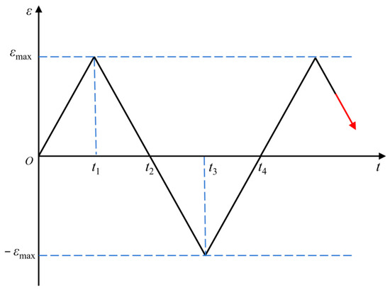
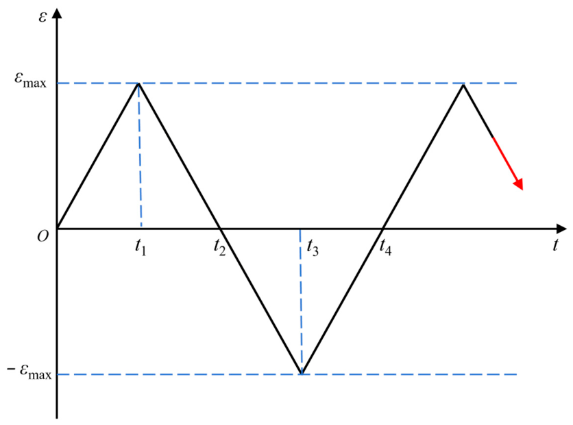
The strain-controlled fatigue tests of 347H stainless steel at 565 °C were conducted in accordance with ASTM E606/E606M-21 [31]. It should be stated that three conditions were included: No pre-corrosion; Pre-corrosion in SS; Pre-corrosion in SS_3.5. The strain amplitudes of ±0.8%, ±0.6%, ±0.4%, and ±0.3% were selected, and the loading waveform was triangular (see Figure 3). The main test parameters were listed below: the strain ratio of Rε = −1, the strain rate of 0.4%/s. During the fatigue tests, the extensometer with a measuring range of 5 mm was used to measure the strain. At least 200 data points were recorded per cycle. The fatigue test was terminated when the maximum force (stress) or elastic modulus decreased by approximately 50%. The detailed test conditions are presented in Table 4. For each strain amplitude and pre-corrosion condition, one specimen was tested. This is because the fatigue data show a good trend with the strain level.
Figure 3.
Loading spectrum for strain-controlled fatigue tests of smooth specimens.
Table 4.
Strain-controlled fatigue test conditions of smooth specimens.
Meanwhile, the fracture surfaces and side morphologies of pre-corrosion fatigue specimens under different environments were observed using SEM to elucidate the pre-corrosion fatigue damage mechanism of 347H stainless steel.
3. Results and Discussion
3.1. Corrosion Kinetics Behavior
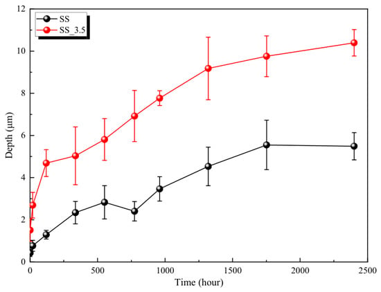
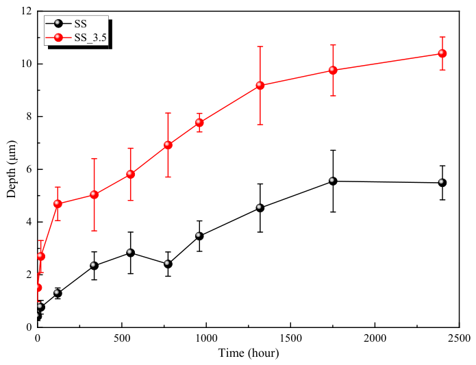
The average oxide layer thickness of 347H stainless steel, measured by cross-sectional SEM (see Section 2.2 for measurement details) after corrosion in SS and SS_3.5 environments, is presented in Figure 4. The symbols represent the mean thickness, and the error bars represent the standard de-viation of multiple oxide-layer thickness measurements taken at different locations on each coupon specimen. It can be observed that the oxide layer thickness in both environments increases with the corrosion time. Meanwhile, the oxide layer thickness on the surface of 347H stainless steel in the SS_3.5 environment is larger than that in the SS environment for the same corrosion time. This indicates that the presence of the chloride ions accelerates the oxide scale growth rate of 347H stainless steel.
Figure 4.
Average oxide layer thickness of 347H stainless steel.
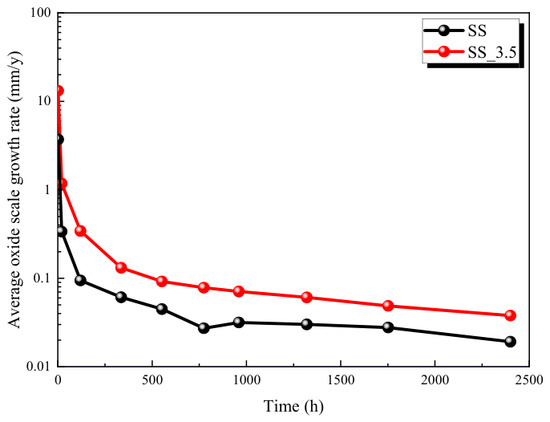
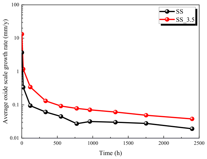
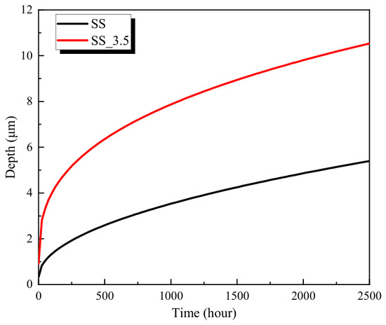
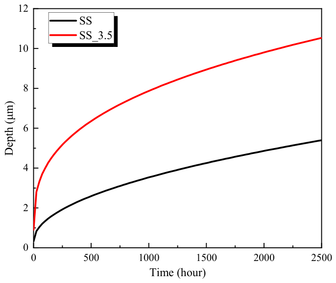
The variations of the oxide scale growth rate of 347H stainless steel with the corrosion time in the SS and SS_3.5 environments are shown in Figure 5. The oxide scale growth rate in both environments gradually decreases with the increasing corrosion time. When the corrosion time is longer than around 500 h, the diffusion barrier effect gradually strengthens with the accumulation of the oxide layer thickness, and the oxide scale growth rate drops over the corrosion time. This is because the molten salt directly contacts the substrate surface in the initial stage of corrosion, resulting in a higher oxide scale growth rate. However, the corrosion products accumulated on the surface could hinder the further corrosion of the substrate by the molten salt, leading to a decrease in the oxide scale growth rate. In the initial stage of corrosion, the oxide scale growth rate in the SS_3.5 environment is approximately 0.342 mm/y, which is significantly higher than that in the SS environment (0.095 mm/y). After the corrosion of 2400 h, the oxide scale growth rate in the SS_3.5 environment is approximately 0.038 mm/y, which is about twice that in the SS environment. Overall, the oxide scale growth rate in the SS_3.5 environment is higher than that in the SS environment in the duration in this work, indicating that the presence of chloride ions not only accelerates the destruction of the initial oxide layer but also weakens the protectiveness of the final oxide layer on the substrate.
Figure 5.
Average oxide scale growth rate curves of 347H stainless steel in SS and SS_3.5 environments.
Based on the corrosion kinetics theory, a power-law model is used to fit the evolution feature of the oxide layer thickness (d) of 347H stainless steel in the SS and SS_3.5 environments, shown in Equation (2).
where, is the corrosion kinetic constant; nc is the exponential constant; d0 is the material parameter.
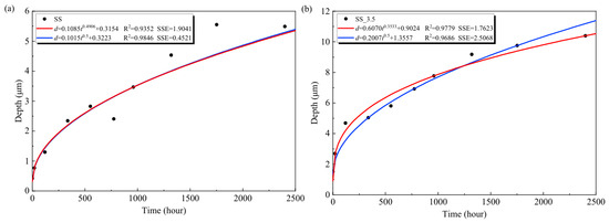
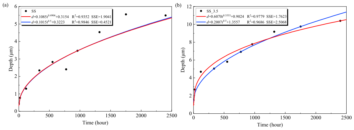
The fitted corrosion kinetic curves of 347H stainless steel in the SS and SS_3.5 environments are shown in Figure 6. Two fitting strategies are adopted in this work: one is based on the fixed exponential constant nc of 0.5, and the other is based on a variable exponential constant nc. The fitted parameters are summarized in Table 5. The coefficient of determination (R2) and the error sum of squares (SSE) are used to evaluate the fitting results. In the SS environment, when nc is fixed at 0.5, the fitted curve yields an R2 of 0.9846 and SSE of 0.4521, superior to the fitting results with a variable parameter nc. This is in good agreement with the classical parabolic growth law, indicating that the oxide layer formed on the surface of 347H stainless steel exhibits good compactness in the absence of Cl−, and the corrosion behavior follows a typical diffusion-controlled process. In the SS_3.5 environment, the equation with a variable parameter nc (nc =0.3533) gives a better fitting result, with an R2 of 0.9779, which exceeds the value of 0.9686 obtained when nc is fixed at 0.5. Since the fitted exponents differ between the two environments, the kinetic constants possess distinct dimensions, rendering a direct numerical comparison invalid. Instead, the corrosion severity is assessed by the actual thickness evolution shown in Figure 7. Throughout the whole testing period, the oxide scale in the SS_3.5 environment grows consistently thicker than that in the SS environment, with the gap widening progressively with time. At 2400 h, the average oxide layer thickness in SS_3.5 is 1.89 times that in SS, confirming that the chloride addition accelerates the corrosion process. This further confirms the accelerating effect of chloride ions on the oxide scale growth rate of 347H stainless steel, and the sub-parabolic growth in the SS_3.5 environment may be related to chloride-assisted scale destabilization, spallation and re-growth; the underlying mechanism requires further verification.
Figure 6.
Corrosion kinetics curves of 347H stainless steel: (a) SS; (b) SS_3.5.
Table 5.
Summary of corrosion kinetic fitting parameters.
Figure 7.
Comparison of corrosion kinetics curves of 347H stainless steel.
In summary, the oxide layer on 347H stainless steel grows following parabolic, diffusion-controlled kinetics (nc = 0.5) in the chloride-free SS environment. However, the chloride-containing SS_3.5 environment exhibits sub-parabolic growth (nc = 0.3533) with a higher growth rate and an approximately two-fold thicker oxide scale at 2400 h.
3.2. Corrosion Surface Morphology
3.2.1. Surface Morphology Analysis
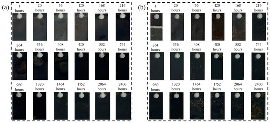
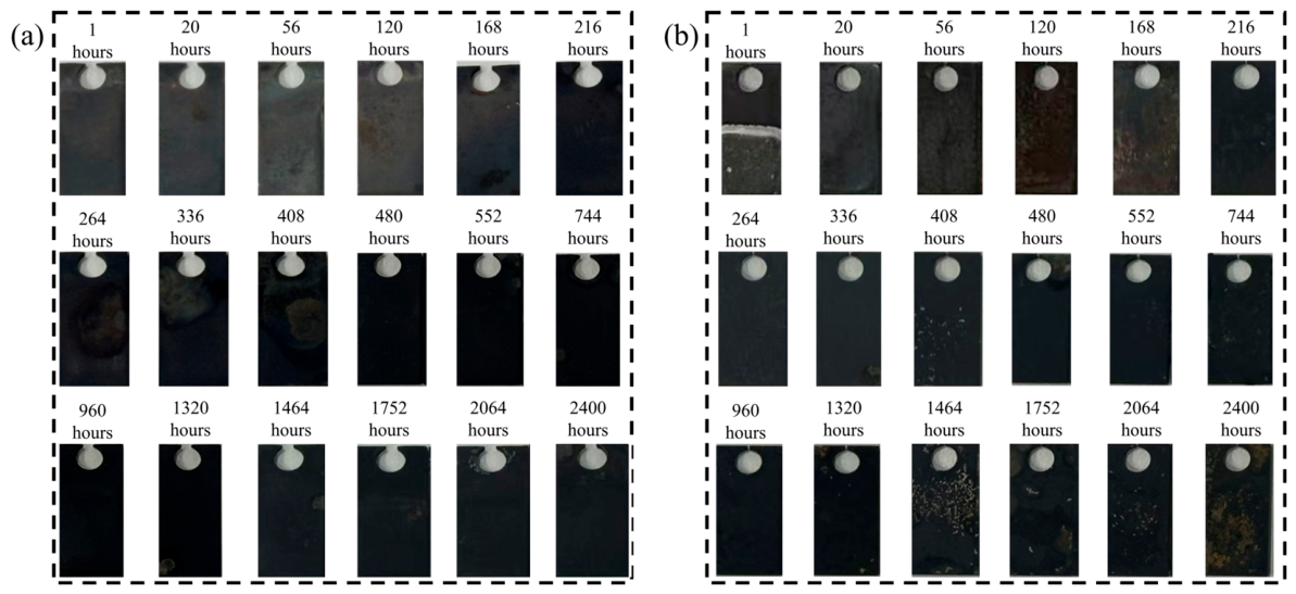
After the static corrosion tests in SS and SS_3.5 environments, the results of the 347H stainless steel coupon specimens are shown in Figure 8. A black corrosion product layer is formed on the surface of the 347H stainless steel specimens. With the increasing corrosion time, the corrosion product layer exhibits some spalling. The spalling mechanism is mainly attributed to the difference in thermal expansion coefficients between the oxide layer and the substrate during the cooling process of the specimen. When the internal stress caused by the thermal mismatch exceeds the fracture strength of the oxide layer, the corrosion layer cracks and spalls off.
Figure 8.
Sheet specimens of static corrosion test: (a) SS; (b) SS_3.5.
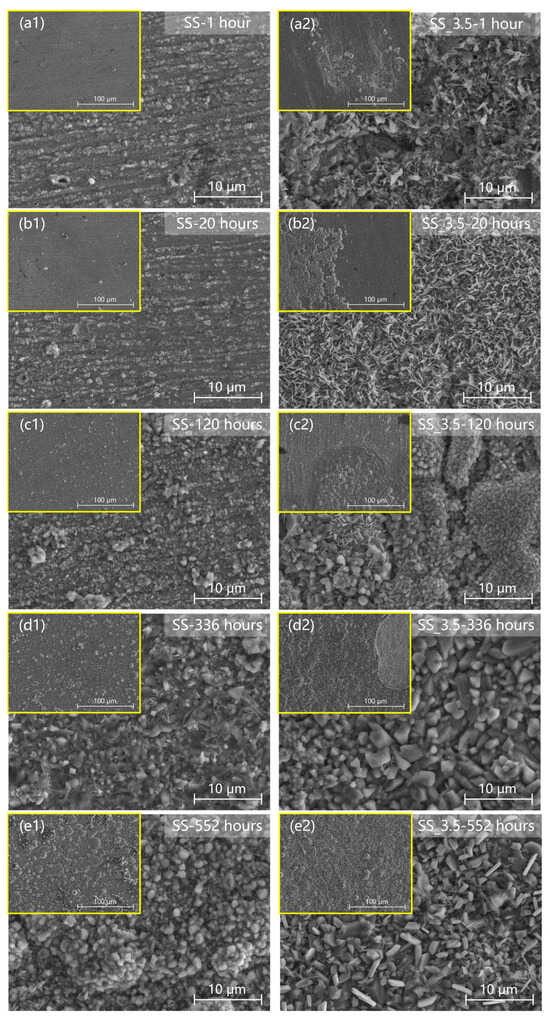
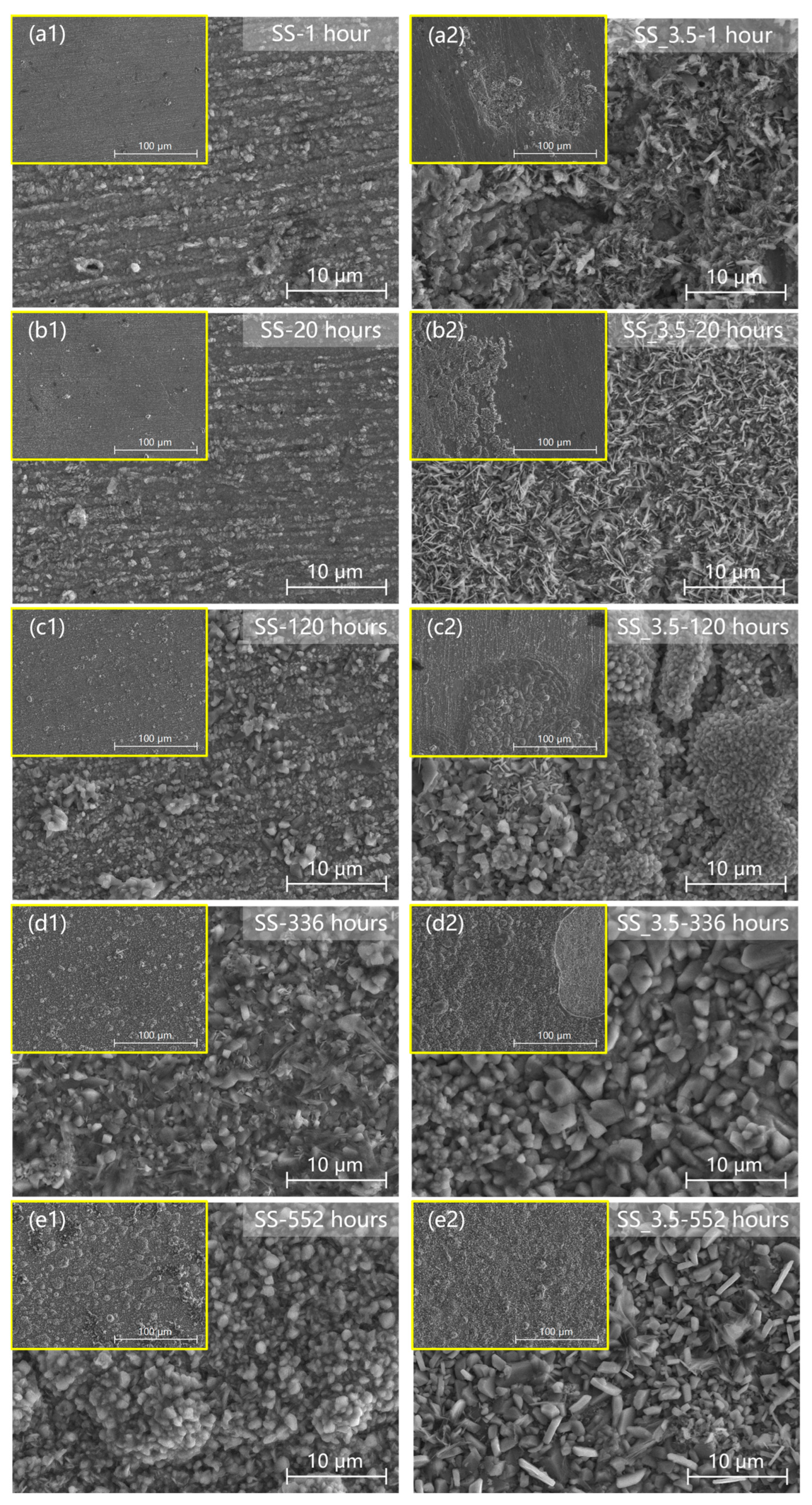
The surface morphologies of 347H stainless steel specimens after the corrosion time points of 1, 20, 120, 336, and 552 h are shown in Figure 9. In the SS environment, the surface oxides exhibit slow and uniform growth characteristics. During the early stage (1–20 h, see Figure 9(a1,b1,a2,b2), the formation and growth of fine oxide particles can be found on the substrate. With the increase of the corrosion time (120–552 h, see Figure 9(c1–e1,c2–e2), the specimen surface is gradually covered with a dense layer of equiaxed particles, indicating a uniform corrosion process controlled by diffusion. In contrast, the SS_3.5 environment significantly accelerates the corrosion kinetics and alters the morphology of the corrosion products. The needle-like products formed in the early stage evolve rapidly into coarse polyhedral crystal blocks, and the corrosion layer becomes visibly more open and porous. Low-magnification SEM observations reveal that the introduction of Cl− accelerates the corrosion kinetics, leading to local cracking and spalling of corrosion products. This can be attributed to Cl− disrupting the compactness of the initial oxide layer and reducing the bonding stability at the layer-substrate interface. Meanwhile, the corrosion process in the SS_3.5 environment is characterized by severe localized corrosion, subsequent spalling of the oxide layer, and then re-corrosion at the spalled areas (see Figure 9(d2)). In contrast, no significant spalling of the oxide layer is observed in the SS environment (see Figure 9(a1–e1)).
Figure 9.
Surface morphologies of 347H stainless steel in various corrosion conditions: (a1) SS-1 h; (a2) SS_3.5-1 h; (b1) SS-20 h; (b2) SS_3.5-20 h; (c1) SS-120 h; (c2) SS_3.5-120 h; (d1) SS-336 h; (d2) SS_3.5-336 h; (e1) SS-552 h; (e2) SS_3.5-552 h.
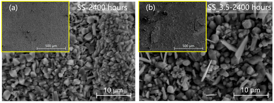
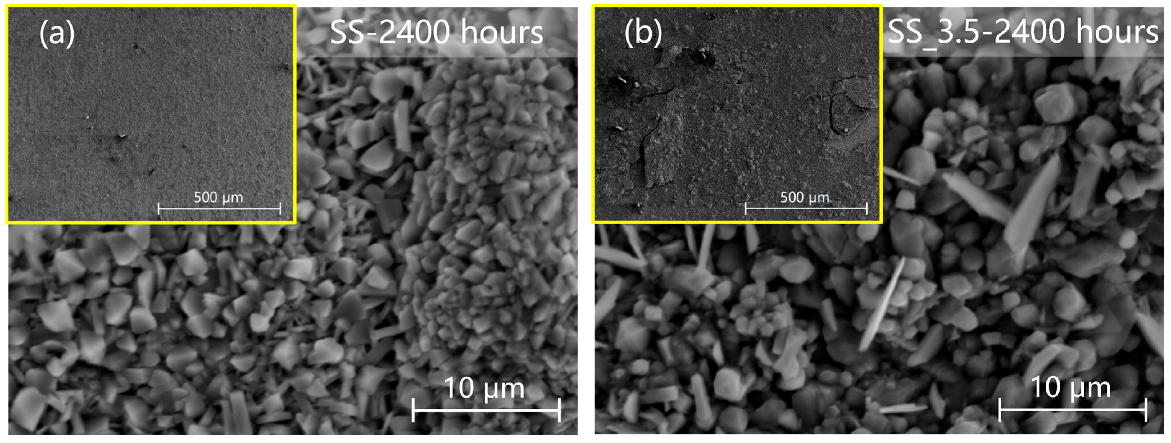
The surface morphology of the 347H stainless steel specimen after the corrosion of 2400 h is shown in Figure 10. Low-magnification SEM images reveal that, in the SS environment, the oxide layer remains continuous and uniform after the corrosion of 2400 h. In the SS_3.5 environment, however, the oxide layer exhibits significant macroscopic cracking and localized spalling, further confirming that the long-term presence of Cl− significantly reduces the stability of the oxide layer. High-magnification SEM images show that the surface in the SS environment consists of the dense polyhedral crystal grains with good structural stability, while the corrosion products in the SS_3.5 environment form a composite oxide layer composed of blocky crystals and numerous needle-like and flake-like crystals. This porous structure reduces the barrier effect against the Cl− diffusion, and its uneven thickness distribution further intensifies the internal stress concentration within the layer.
Figure 10.
Surface morphologies of 347H stainless steel after corrosion of 2400 h: (a) SS; (b) SS_3.5.
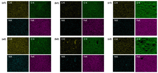
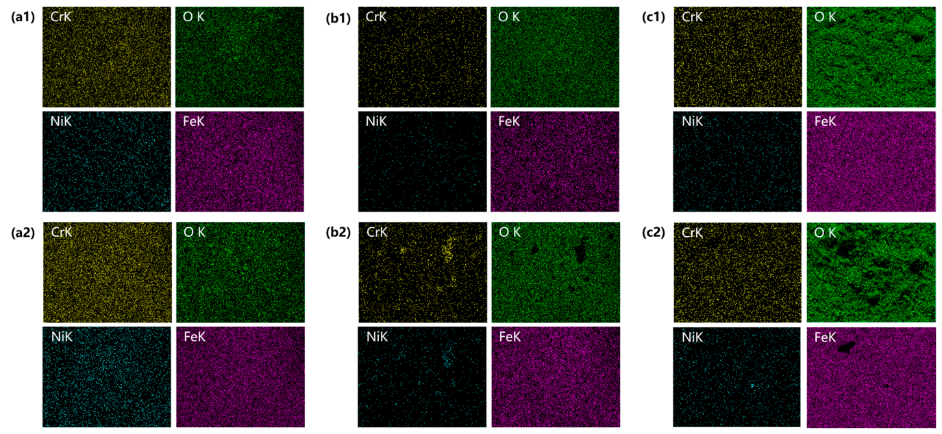
The EDS mapping results of 347H stainless steel after the corrosion of 1, 552 and 2400 h are shown in Figure 11. In the SS environment, the signal intensity of oxygen gradually increases and remains uniformly distributed with the corrosion time, indicating that the oxide layer is formed uniformly and continuously on the substrate surface. In the SS_3.5 environment, the oxygen signal exhibits heterogeneous features after the corrosion time of 552 h, and the surface composition shows patchy segregation after the corrosion time of 2400 h. Meanwhile, the introduction of Cl− affects the diffusion paths of metallic elements, leading to segregation of Cr and Fe. This indicates that Cl− disrupts the compactness of the initial oxide layer, inducing the non-uniform outward migration of metal cations and the transformation of the oxide layer structure from dense to porous morphology. In addition, the Ni content on the specimen surface decreases with the corrosion time in both environments. This suggests that Ni either enriches at the substrate/oxide interface or is lost into the molten salt through gaps in the oxide layer, weakening the corrosion resistance of the material.
Figure 11.
EDS analysis results (mapping) of 347H stainless steel after corrosion of 1, 552 and 2400 h: (a1) SS-1 h; (a2) SS_3.5-1 h; (b1) SS-552 h; (b2) SS_3.5-552 h; (c1) SS-2400 h; (c2) SS_3.5-2400 h.
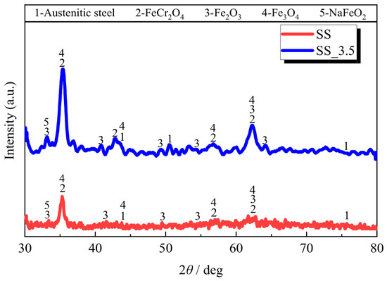
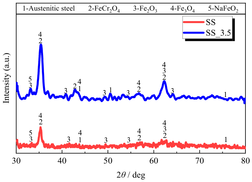
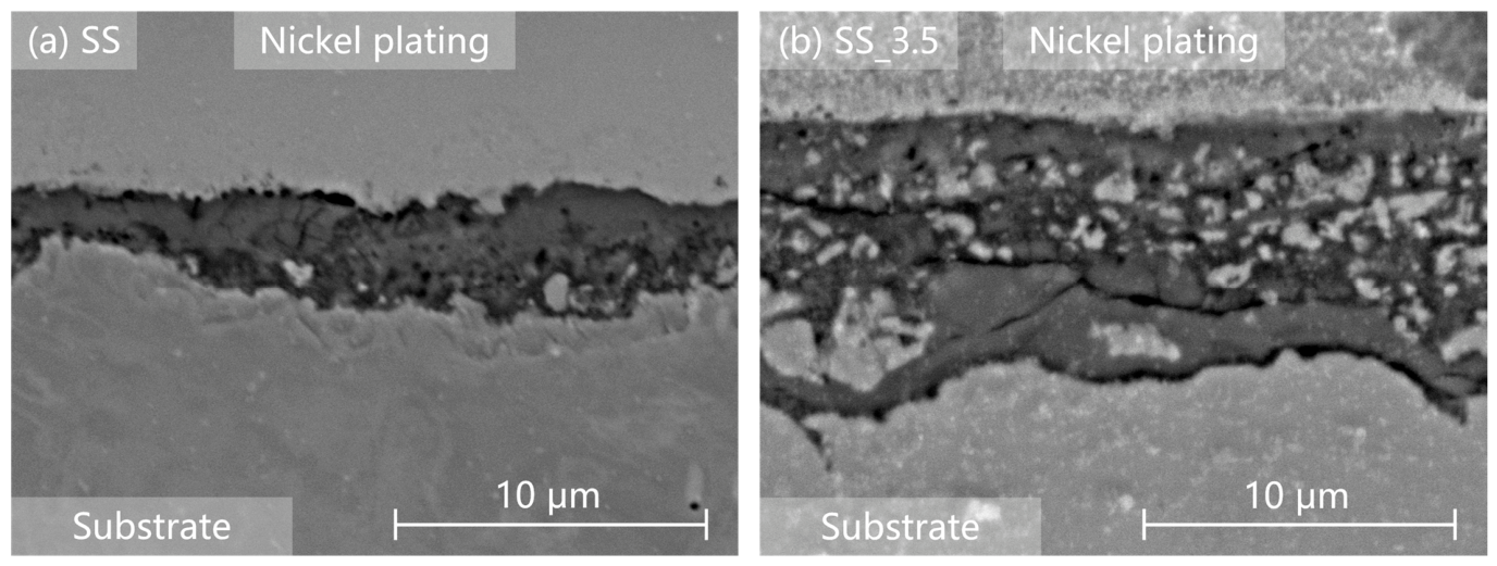
The GIXRD pattern results of 347H stainless steel after the corrosion of 2400 h are shown in Figure 12. The diffraction peaks of 347H stainless steel in the SS_3.5 environment mainly correspond to spinel-type oxides (FeCr2O4 or Fe3O4) and hematite (Fe2O3), and sodium ferrite (NaFeO2). In both corrosive environments, no characteristic peaks of Cr2O3 are detected, suggesting that Cr combines with Fe to form complex composite oxides rather than a single Cr2O3 protective layer. The lower diffraction peak intensity in the SS environment indicates a thinner oxide layer (see Figure 13a). In contrast, the higher peak intensity in the SS_3.5 environment suggests a thicker oxide scale (see Figure 13b). These observations are consistent with the Cl−-accelerated corrosion kinetics and are directly supported by the thicker oxide scale observed in the SEM cross-sectional images (see Figure 13). Although the presence of Cl− affects the corrosion severity, the types of corrosion products on the surface remain essentially the same in both environments, and no chlorine-containing corrosion products are detected.
Figure 12.
GIXRD spectra of 347H stainless steel after corrosion for 2400 h in SS and SS_3.5 environments.
Figure 13.
Cross-sectional morphologies of corrosion layer on 347H stainless steel after corrosion of 2400 h: (a) SS; (b) SS_3.5.
3.2.2. Cross-Sectional Morphological Analysis
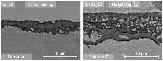
The cross-sectional morphology of 347H stainless steel after the corrosion of 2400 h is shown in Figure 13. In the SS environment, the oxide layer is tightly bonded to the substrate interface. However, the oxide layer thickness increases and exhibits a porous structure in the SS_3.5 environment. This indicates that Cl− affects the growth mode of the oxide layer, transforming it from a relatively uniform diffusion-controlled process to an accelerated corrosion process dominated by layer defects. Horizontal through-thickness cracks are observed in the oxide layer cross-section in the SS_3.5 environment, attributed to the different phase compositions of the inner and outer oxide layers. A large thermal stress within the layer can be induced by the mismatch in thermal expansion coefficients, leading to destabilization and cracking of the oxide layer. Stress concentration arises at these cracked regions of the oxide layer, which act as preferential fatigue crack initiation sites.
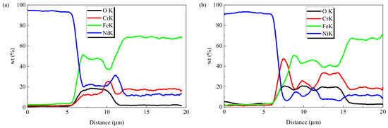
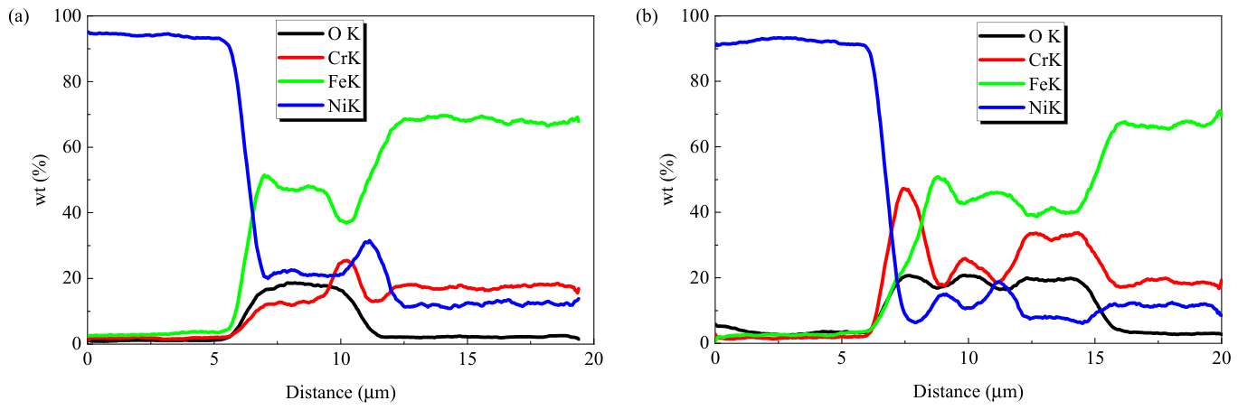
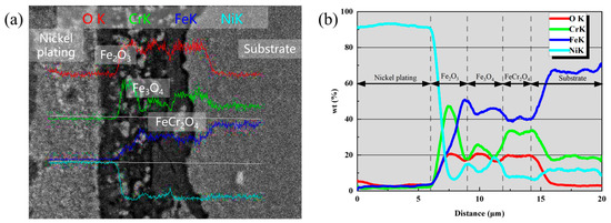
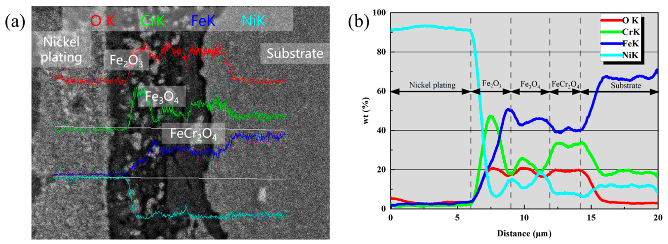
The EDS line scan results of the corrosion layer of 347H stainless steel after the corrosion of 2400 h are shown in Figure 14. In the SS environment, the elemental distribution exhibits stratified characteristics, with Cr enriching at the oxide layer–substrate interface to form a dense chromium-rich spinel inner layer, which restricts the inward diffusion of O. Nevertheless, the line scan shows local variation in the Cr signal near the oxide–substrate interface in the SS specimen, where the Cr signal locally drops below the matrix level (see Figure 14a). As proposed in Ref. [32], one possible mechanism is that grain boundaries may act as short-circuit diffusion paths, allowing the outward migration and dissolution of Cr to proceed preferentially along these boundaries during long-term exposure. This could result in mild intergranular attack beneath the otherwise uniform and protective oxide layer. In contrast, in the SS_3.5 environment, the Cr and Fe signals fluctuate dramatically within the layer, indicating that Cl− disrupts the uniform growth of the chromium-rich layer, leading to rapid oxidation of metallic elements and the formation of multiphase mixed products. In the SS_3.5 environment, chromium depletion occurs in the substrate, with Cr showing an attenuation trend in the substrate surface layer. The chromium-depleted zone weakens the corrosion resistance of the material.
Figure 14.
EDS analysis results (line scan) of 347H stainless steel after corrosion of 2400 h: (a) SS; (b) SS_3.5.
In summary, the SS environment produces a uniform and well-bonded oxide layer on 347H stainless steel. In contrast, the SS_3.5 environment yields a thicker and defective oxide scale with local cracking and spallation, through-thickness cracks and substrate chromium depletion. Although the oxide phases (Fe-Cr spinel and iron oxides) are essentially the same in both environments, Cl− disrupts the compactness and uniformity of the scale. As a result, the corrosion morphology changes from a dense, diffusion-controlled structure to a loose and heterogeneous one.
3.3. Corrosion Mechanism of 347H Stainless Steel in Nitrate Molten Salt
In the SS environment, the corrosion process of 347H stainless steel is mainly controlled by selective oxidation and dissolution reactions of elements. It can be divided into three stages:
- (1)
- Formation and evolution of oxidation products: In the initial stage, Fe, Cr, and Ni in the substrate are oxidized to their corresponding oxides, such as Fe3O4, Cr2O3, and NiO. Due to the low solubility of iron oxides in the molten salt environment, they continuously nucleate and grow on the metal surface until it is covered, forming a moderately protective oxide layer, the main reactions are shown in Equations (3) and (4). The released electrons are consumed by oxidizing species (e.g., nitrate ions) in the molten salt, maintaining overall charge neutrality.
- (2)
- Cr depletion process: In contrast, Cr2O3 has a relatively high solubility in nitrate salts containing oxide ions, undergoing a solvation reaction to form soluble chromate (appearing yellowish-green), leading to chromium depletion in the substrate surface layer, shown in Equation (5).
- (3)
- Formation of the layered structure: At this stage, a molten salt–oxide layer–substrate structure is formed, and the oxide layer mainly consists of iron oxides. Since Fe ions diffuse from the substrate into the molten salt during the corrosion process, the oxygen partial pressure in the substrate is lower than that in the molten salt region. Fe2O3 exists in regions with higher oxygen partial pressure, while Fe3O4 exists in regions with lower oxygen partial pressure. Consequently, a layered structure with an outer Fe2O3 layer and an inner Fe3O4 layer is formed (see Figure 15a). During this process, the outward migration and dissolution of Cr may preferentially proceed along short-circuit diffusion paths, such as grain boundaries, during long-term exposure in chloride-containing molten salts [32]. The second is spinel formation in the inner corrosion layer. The other part of Cr undergoes a solid-state reaction with the formed iron oxides at the inner interface near the substrate, forming a dense FeCr2O4 spinel phase (see Equation (6)), as evidenced by the interfacial Cr enrichment in the EDS line scan result (see Figure 15b). At this stage, the oxide scale growth rate is controlled by solid-state diffusion of ions through this duplex oxide layer, exhibiting parabolic kinetic characteristics.Figure 15. Corrosion layer structure of 347H stainless steel in molten salt: (a) specimen; (b) EDS.
In the SS_3.5 environment, the presence of chloride impurities modifies the corrosion process. The following reactions describe a possible oxidation-chlorination mechanism [32]. Similar chloride-associated scale destabilization and oxidation-chlorination behavior have been reported for 347 stainless steel in molten solar salt [15].
- (1)
- In oxidizing nitrate molten salts, Cl− generates Cl2 through electrochemical oxidation or by reacting with oxidizing species in the molten salt (see Equation (7)).
- (2)
- The released Cl2 rapidly penetrates through pores or cracks in the oxide layer to the metal/oxide interface. Due to the high charge density of Cl, it competes with O for adsorption at the interface, hindering the formation of Cr2O3 and disrupting the chemical equilibrium at the interface.
- (3)
- At the metal/oxide interface with low oxygen partial pressure, Cl2 reacts with substrate metal atoms (primarily Fe in iron-based metals) to form solid FeCl2 (see Equation (8)). The FeCl2 may participate in an oxidation-chlorination (active oxidation) cycle through defects in the oxide scale, potentially promoting outward transport of metal species and repeated oxide formation.
- (4)
- When the metal chlorides are transported outward to a region with higher oxygen partial pressure, they may be oxidized to loose iron oxides with Cl2 released again. The released Cl2 returns to step (2) to participate in the cycle, causing the corrosion layer on the surface to thicken continuously while remaining relatively loose in structure.
The chlorine cycle mechanism may allow metal atoms to bypass the limitation of ion diffusion through the solid oxide layer, potentially promoting outward transport of metal species and repeated scale formation. Consequently, microstructural characterization reveals loose, needle-like and flake-like corrosion products, and the oxide scale growth rate under chloride-containing conditions is higher than that under chloride-free conditions. Therefore, the oxide scale formed under chloride-containing conditions is thicker than that under chloride-free conditions.
3.4. Fatigue Deformation Behavior and Failure Life
3.4.1. Cyclic Hardening and Softening Characteristics
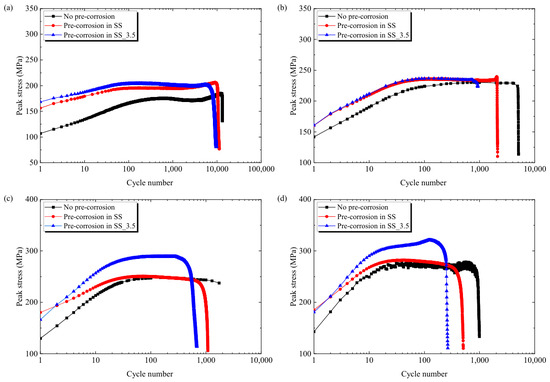
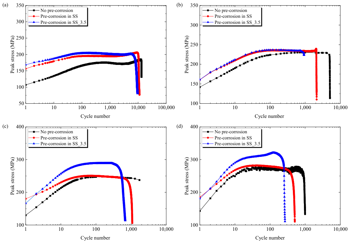
The cyclic deformation curves of 347H stainless steel in the Air, SS, and SS_3.5 environments are shown in Figure 16, where the data in the air environment are collected from Ref. [33]. It can be found that the pre-corrosion alters the cyclic stress response and fatigue life of 347H stainless steel, while the cyclic hardening feature is retained in all three conditions. In each pre-corrosion environment, the peak stress increases rapidly with the cycle number during the initial stage, exhibiting a cyclic hardening phenomenon. As the strain amplitude increases, the degree of cyclic hardening intensifies and the peak stress level rises. Compared with the unexposed specimens under the present test conditions, the SS and SS_3.5 environments yielded generally higher peak cyclic stress and shorter fatigue failure life. Moreover, the fatigue failure life of 347H stainless steel in the SS_3.5 environment was smaller than that in the SS environment. This may be partly attributed to the corrosion layer (brittle oxide layer and Cr-depleted zone), which can induce stress concentration and potentially accelerate fatigue crack initiation and propagation. A rapid decrease in fatigue life in the SS_3.5 environment was observed under the present conditions.
Figure 16.
Cyclic softening/hardening behavior of 347H stainless steel under pre-corrosion fatigue: (a) ±0.3%; (b) ±0.4%; (c) ±0.6%; (d) ±0.8%.
In addition, the 2400 h pre-corrosion exposure at 565 °C constitutes a significant thermal aging process. At a strain amplitude of ±0.3%, secondary hardening occurred in this material, macroscopically manifested as an increase in cyclic stress. This behavior has been reported in many kinds of austenitic stainless steels with a small strain amplitude in previous works [34,35,36], although the air environment is different from the pre-corrosion condition in this work.
3.4.2. Stress-Strain Hysteresis Loop
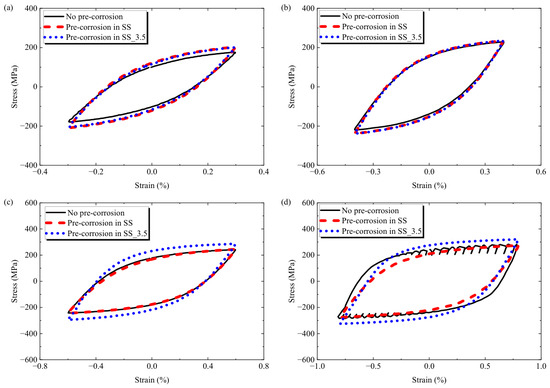
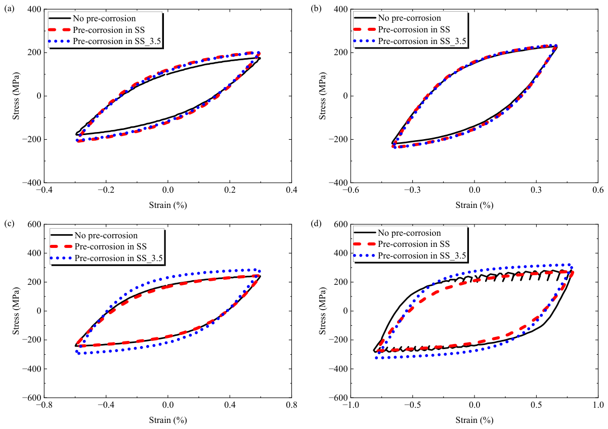
The half-life cyclic hysteresis loops of 347H stainless steel in the Air, SS, and SS_3.5 environments are shown in Figure 17, where the data in the air environment are collected from Ref. [33]. Overall, the hysteresis loops at different strain amplitudes exhibit good closure characteristics. As the strain amplitude increases, the area enclosed by the hysteresis loop gradually enlarges, indicating that the energy dissipated per cycle increases. Moreover, the hysteresis loops at various strain amplitudes are essentially symmetric in the tension and compression directions.
Figure 17.
Comparison of half-life hysteresis loops of 347H stainless steel in various conditions: (a) ±0.3%; (b) ±0.4%; (c) ±0.6%; (d) ±0.8%.
It should be noted that, at the strain amplitude of ±0.8%, the uncorroded specimen exhibits clear DSA serrations on the hysteresis loops (Figure 17d), whereas no such serrations are observed for either the SS or SS_3.5 pre-corroded specimens. The DSA phenomenon occurs at specific temperature and strain rate conditions [37]. The solute atoms diffuse and accumulate around moving dislocations, forming Cottrell atmospheres that pin the dislocations. When the dislocations break away from the pins under applied stress, the solute atoms re-pin the dislocations through short-range diffusion [38]. This dynamic interaction results in intermittent dislocation motion, which macroscopically manifests as serrated features. The corrosive environment causes continuous loss of metal cations from the substrate, introduces numerous crystal defects (such as vacancies) on the specimen surface, and destroys the compact oxide layer. Because the fatigue tests were conducted after pre-corrosion rather than under simultaneous molten-salt exposure, the difference in DSA behavior cannot be attributed to ongoing anodic dissolution during cyclic loading. The present observations only indicate that pre-corrosion modifies the subsequent cyclic response; the mechanism responsible for the suppression of the serrated-flow feature requires further investigation [39].
3.4.3. Fatigue Failure Life
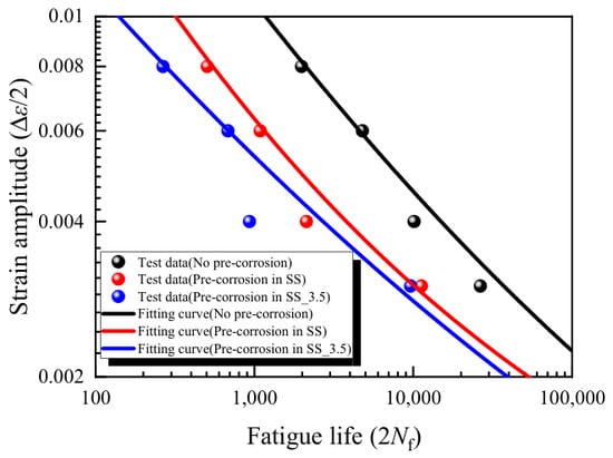
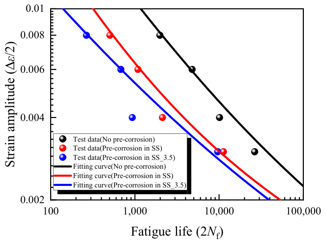
In low-cycle fatigue analysis, the Manson-Coffin equation [40,41] is used to describe the relationship between the fatigue failure life and the strain amplitude (see Equation (9)). Based on the strain-controlled fatigue test data of 347H stainless steel in various test conditions, the material parameters in the equation are fitted (see Table 6), and the fitting results are shown in Figure 18.
where, is the fatigue strength coefficient; b is the fatigue strength exponent; is the fatigue ductility coefficient; c is the fatigue ductility exponent.
Table 6.
Material parameters in Manson-Coffin equation of 347H stainless steel.
Figure 18.
Fitted fatigue life curves for 347H stainless steel in various test conditions.
The experimental results indicate that the fatigue failure life exhibits a trend of Nf(air) > Nf(SS) > Nf(SS_3.5) for a specific strain amplitude. This is mainly attributed to the roughening of the surface morphology (see Section 3.2) and the transition of the fatigue crack initiation mechanism (see Section 3.5). The pre-corrosion treatments (SS and SS_3.5) lead to different degrees of the surface damage. In the SS environment, a uniform oxide layer forms on the surface accompanied by minimal metal loss, and the microscopic surface roughening occurs over the entire surface. These micro-undulations become preferential sites for fatigue crack initiation, resulting in a shorter fatigue failure life in the SS environment than that in the air environment. In the SS_3.5 environment, Cl−-induced corrosion produces a thicker and more defective oxide scale with local cracking and spallation, creating more severe local surface damage and potential stress concentration sites. In addition, the near-surface Cr signal variation observed beneath the corrosion layer (Figure 14) may be associated with localized near-surface damage; the preferential cracking features observed on the fracture surfaces (Figure 19). As a result, fatigue cracks can initiate earlier and propagate faster in the SS_3.5 environment, leading to a greater reduction in fatigue life than that in the SS environment. These findings provide experimentally based reference data for evaluating the effects of long-term molten-salt exposure on the subsequent fatigue behavior of 347H stainless steel, and highlight that chloride impurities and oxide-scale integrity should be considered in the environmental ageing and fatigue assessment of high-temperature molten salt storage components.
Figure 19.
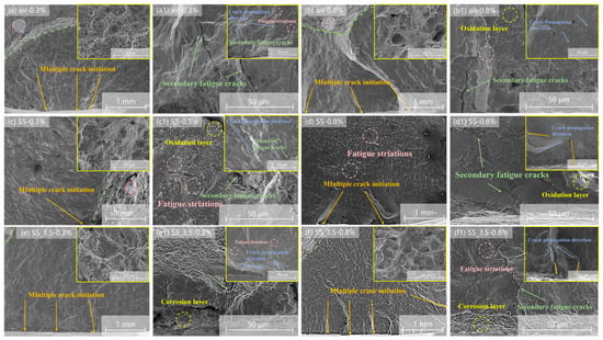
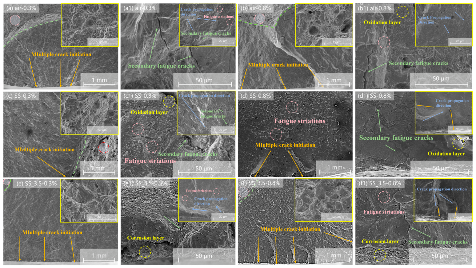
Fracture surface morphology observation of 347H stainless steel: (a) no pre-corrosion-±0.3% (×30); (a1) no pre-corrosion-±0.3% (×1000); (b) no pre-corrosion-±0.8% (×30); (b1) no pre-corrosion-±0.8% (×1000); (c) pre-corrosion in SS-±0.3% (×30); (c1) pre-corrosion in SS-±0.3% (×1000); (d) pre-corrosion in SS-±0.8% (×30); (d1) pre-corrosion in SS-±0.8% (×1000); (e) pre-corrosion in SS_3.5-±0.3% (×30); (e1) pre-corrosion in SS_3.5-±0.3% (×1000); (f) pre-corrosion in SS_3.5-±0.8% (×30); (f1) pre-corrosion in SS_3.5-±0.8% (×1000).
3.5. Fatigue Fracture and Lateral Morphology
The SEM characterization of the fracture surfaces and the side surfaces near the fracture is performed on uncorroded specimens (Air) and pre-corroded specimens (SS and SS_3.5) (see Figure 19). Two strain amplitudes of ±0.3% and ±0.8% are considered for analysis. For the Air environment, the fatigue source is located on the specimen surface, and the fracture surface is relatively flat (see Figure 19(a,a1)). Meanwhile, the fracture surface roughness increases with the strain amplitude. A step-like morphology appears in the crack initiation zone, and secondary cracks initiate along grain boundaries or slip bands (see Figure 19(b,b1)). The spacing between fatigue striations in the propagation zone increases, indicating an increase in crack growth rate (see Figure 19(b,b1)). For the SS environment, the specimen at the strain amplitude of ±0.3% shows a thin, relatively intact oxide layer at the fracture edge. The crack initiation sites are located at the oxide layer–substrate interface, exhibiting multi-site crack initiation characteristics (see Figure 19(c,c1)). The fatigue propagation zone exhibits grain-boundary cracking, and the number of secondary fatigue cracks significantly increases, suggesting that the near-surface damage induced by pre-corrosion may weaken the grain boundaries. For the specimen at the strain amplitude of ±0.8%, the fracture surface roughness further increases, but the spacing of fatigue striations becomes irregular (see Figure 19(d,d1)). For the SS_3.5 environment, multiple cracks initiate simultaneously from the oxide layer–substrate interface, and a considerable gap between the surface oxide layer and the substrate is observed (see Figure 19(e,e1)). The fatigue propagation zone is dominated by cracking along grain boundaries, possibly weakened by near-surface Cr variation or localized corrosion [32] (see Figure 19(f,f1)).
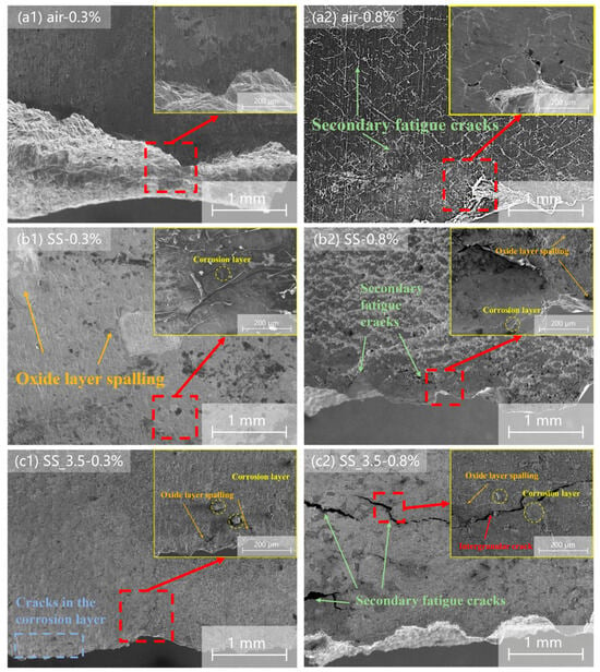
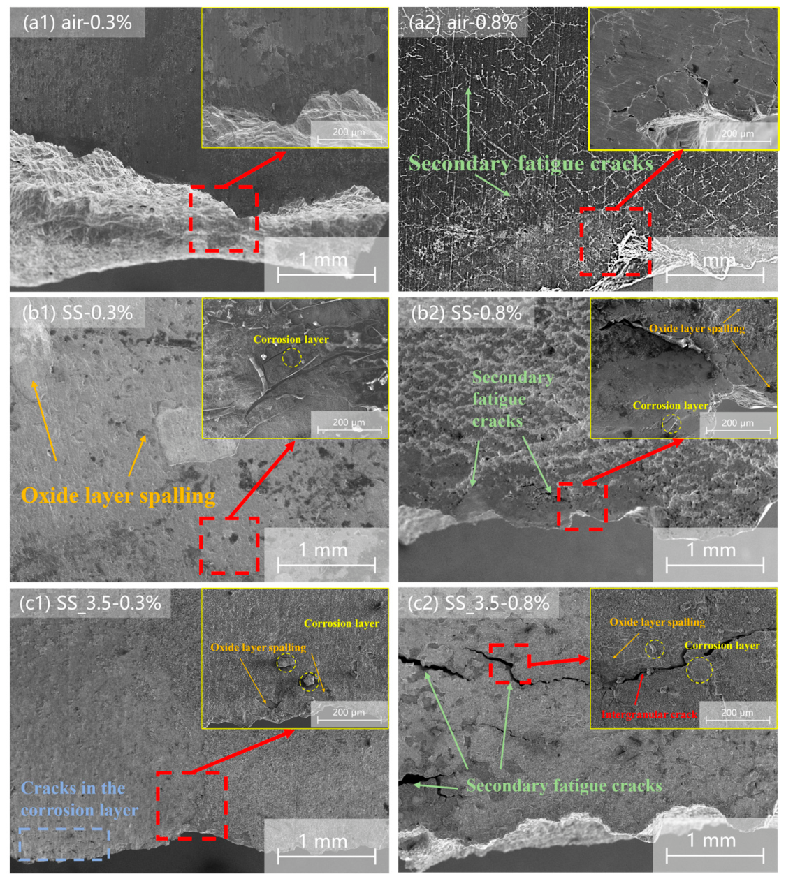
The side surface morphologies near the fracture of the specimens are shown in Figure 20. For the Air environment, at a strain amplitude of ±0.3%, the side surface is relatively smooth, with only slight oxide layer spalling in some areas and no obvious secondary cracks (see Figure 20(a1)). At a strain amplitude of ±0.8%, the secondary crack propagation paths show a network-like distribution (see Figure 20(a2)), indicating dislocation slip in the material, formation of persistent slip bands, and extrusion/intrusion structures on the surface, ultimately leading to the initiation of fatigue microcracks on the specimen surface. For the SS environment, at a strain amplitude of ±0.3%, oxidation and spalling of the corrosion layer occur on the side surface, and the relatively compact surface corrosion layer cracks under loading (see Figure 20(b1)). At a strain amplitude of ±0.8%, the corrosion layer exhibits step-like spalling and the secondary cracks perpendicular to the loading direction are visible near the fracture surface (see Figure 20(b2)). For the SS_3.5 environment, at a strain amplitude of ±0.3%, a few secondary cracks are observed initiated at the bottom of the corrosion layer (see Figure 20(c1)). At a strain amplitude of ±0.8%, relatively coarse secondary cracks propagate perpendicular to the loading direction, with crack branching and density greater than those in the SS and air environments (see Figure 20(c2)).
Figure 20.
Side surface morphology observed near the fracture of 347H stainless steel: (a1) no pre-corrosion-±0.3%; (a2) no pre-corrosion-±0.8%; (b1) pre-corrosion in SS-±0.3%; (b2) pre-corrosion in SS-±0.8%; (c1) pre-corrosion in SS_3.5-±0.3%; (c2) pre-corrosion in SS_3.5-±0.8%.
In summary, the uncorroded specimens indicate typical surface-initiated failure features with striation-dominated crack propagation. In contrast, the pre-corroded specimens exhibit multi-site crack initiation at the oxide layer-substrate interface, accompanied by cracking along grain boundaries, possibly weakened by near-surface Cr variation and localized pre-corrosion damage [32], as well as numerous secondary cracks. These corrosion-induced damage features promote earlier and faster crack initiation and propagation. This is more evident in the SS_3.5 environment, where the spalled oxide scale and possibly weakened grain boundaries may further contribute to the reduction in fatigue failure life.
4. Conclusions
In this work, the corrosion behavior of 347H stainless steel in nitrate molten salts at 565 °C was investigated, with particular attention to chloride impurities. The effects of pre-corrosion on cyclic deformation characteristics, fatigue life, and failure mechanisms were discussed. The main conclusions are as follows:
The oxide-scale growth of 347H stainless steel in the chloride-free nitrate salt follows an approximately parabolic kinetic law (nc = 0.5), indicating diffusion-controlled scale growth. In the chloride-containing salt with 3.5 wt% NaCl, it exhibits a lower kinetic exponent (nc = 0.3533), suggesting a deviation from ideal diffusion-controlled scale growth. The chloride-containing environment also produces a thicker and more heterogeneous oxide scale, with the oxide thickness at 2400 h being approximately twice that in the chloride-free salt.
The pre-corrosion does not change the overall cyclic hardening characteristic of 347H stainless steel at 565 °C, but significantly reduces its fatigue life. At a given strain amplitude, the fatigue life decreases in the order of air > SS > SS_3.5. The fitted Manson-Coffin parameters provide reference material data for strain-life assessment after the pre-corrosion in molten-salt.
The fatigue life reduction is closely associated with the corrosion-induced surface damage state. In the chloride-free environment, relatively uniform oxide growth produces surface roughening and preferential crack-initiation sites. In the chloride-containing environment, oxide-scale cracking and spallation generate more severe local surface damage, resulting in a greater reduction in fatigue life.
Fracture-surface observations show that uncorroded specimens exhibit surface-initiated fatigue cracking with predominantly striation-dominated propagation, whereas pre-corroded specimens show multi-site crack initiation near the oxide layer-substrate interface and more pronounced cracking along grain boundaries. These features are most evident in the chloride-containing environment, consistent with its shortest fatigue life.
The long-term molten-salt corrosion affects subsequent fatigue performance not only by increasing the extent of surface degradation, but also by changing the type and severity of the damage that controls fatigue crack initiation. The distinct effects of chloride-free and chloride-containing environments should be considered in the ageing and fatigue assessment of 347H stainless steel in nitrate molten salt storage systems.
Author Contributions
Conceptualization, H.C., X.-J.S., J.-G.G., Y.-H.H. and F.-Z.X.; Methodology, H.-Y.L., X.-J.S., J.-G.G., Y.-H.H. and F.-Z.X.; Validation, H.C.; Formal analysis, H.C. and H.-Y.L.; Data curation, H.C.; Writing—original draft, H.C.; Writing—review & editing, J.-G.G. and Y.-H.H.; Supervision, J.-G.G. and Y.-H.H. All authors have read and agreed to the published version of the manuscript.
Funding
Supports from the National Key Research and Development Program of China (No.: 2023YFF0614900) are greatly acknowledged.
Data Availability Statement
The original contributions presented in this study are included in the article. Further inquiries can be directed to the corresponding authors.
Conflicts of Interest
The authors declare no conflict of interest.
References
- Sun, H.; Su, X.Z.; Zhang, P.; Wang, J.Q. Research status and progress of molten salts corrosion for concentrated solar thermal power. Corros. Sci. Prot. Technol. 2017, 29, 282–290. [Google Scholar]
- Wu, Y.T.; Ren, N.; Ma, C.F. Research and application of molten salts for sensible heat storage. Energy Storage Sci. Technol. 2013, 2, 586–592. [Google Scholar]
- Hong, S.-M.; Min, D.-J.; Chung, Y.-K.; Kim, J.-H.; Kim, D.-I.; Suh, J.-Y.; Shim, J.-H.; Jung, W.-S.; Choi, I.-S. Effect of preexisting plastic deformation on the creep behavior of TP347 austenitic steel. Mater. Sci. Eng. A 2016, 654, 390–399. [Google Scholar] [CrossRef] [Scilit]
- Che, C.; Yan, K.; Ma, S.H.; Qian, G. Creep behaviour and microstructural evolution for TP347H austenite steel used in China power plants. Mater. High Temp. 2022, 39, 572–577. [Google Scholar] [CrossRef] [Scilit]
- Pickle, T.; Augustine, C.; Yu, Z. Mechanical Failure Risk Management for In-Service CSP Nitrate Hot Tanks (NREL/TP-5700-87615); National Renewable Energy Laboratory: Golden, CO, USA, 2024. [Google Scholar]
- Baraka, A.; Abdel-Rohman, A.I.; El Hosary, A.A. Corrosion of mild steel in molten sodium nitrate-potassium nitrate eutectic. Br. Corros. J. 1976, 11, 44–46. [Google Scholar] [CrossRef]
- Fernández, Á.G.; Cabeza, L.F. Molten salt corrosion mechanisms of nitrate based thermal energy storage materials for concentrated solar power plants: A review. Sol. Energy Mater. Sol. Cells 2019, 194, 160–165. [Google Scholar] [CrossRef] [Scilit]
- Cheng, W.-J.; Chen, D.-J.; Wang, C.-J. High-temperature corrosion of Cr-Mo steel in molten LiNO3-NaNO3-KNO3 eutectic salt for thermal energy storage. Sol. Energy Mater. Sol. Cells 2015, 132, 563–569. [Google Scholar] [CrossRef] [Scilit]
- Soleimani Dorcheh, A.; Durham, R.N.; Galetz, M.C. Corrosion behavior of stainless and low-chromium steels and IN625 in molten nitrate salts at 600 °C. Sol. Energy Mater. Sol. Cells 2016, 144, 109–116. [Google Scholar] [CrossRef] [Scilit]
- Zhang, X.M.; Zhang, C.C.; Wu, Y.T.; Lu, Y.W. Experimental research of high temperature dynamic corrosion characteristic of stainless steels in nitrate eutectic molten salt. Sol. Energy 2020, 209, 618–627. [Google Scholar] [CrossRef] [Scilit]
- Fernandez, A.G.; Galleguillos, H.; Fuentealba, E.; Perez, F.J. Corrosion of stainless steels and low-Cr steel in molten Ca(NO3)2-NaNO3-KNO3 eutectic salt for direct energy storage in CSP plants. Sol. Energy Mater. Sol. Cells 2015, 141, 7–13. [Google Scholar] [CrossRef] [Scilit]
- Li, N.; Tariq, N.U.H.; Han, B.T.; He, R.; Wang, J.; Cui, X.; Xiong, T. Study of corrosion performance and mechanisms of P91, 304SS and IN625 alloys in molten nitrate salts used for thermal energy storage system. Metals 2023, 13, 806. [Google Scholar] [CrossRef] [Scilit]
- Fernández, A.; Pérez, F. Improvement of the corrosion properties in ternary molten nitrate salts for direct energy storage in CSP plants. Sol. Energy 2016, 134, 468–478. [Google Scholar] [CrossRef] [Scilit]
- Liu, Q.; Wang, C.; Qian, J.; Pessu, F. Investigation of the early stage corrosion characteristics of molten (nitrate) salt-oxide-metal interfaces, and the links to interfacial thermo-mechanical stress. Corros. Sci. 2023, 220, 111282. [Google Scholar] [CrossRef] [Scilit]
- Wang, Y.L.; Huang, J.N.; Liu, H.J.; Yan, L.X.; Zeng, C.L. Effect of chlorides and sulfates on the corrosion of SS347 and GH3539 in molten solar salt. Sol. Energy Mater. Sol. Cells 2024, 270, 112820. [Google Scholar] [CrossRef] [Scilit]
- Pineau, A.; Antolovich, S.D. High temperature fatigue: Behaviour of three typical classes of structural materials. Mater. High Temp. 2015, 32, 298–317. [Google Scholar] [CrossRef] [Scilit]
- Suresh Kumar, T.; Dash, M.K.; Nagesha, A. Deformation and damage assessment in type 316 LN stainless steel weld joint under isothermal and thermomechanical cyclic loading. Mater. Sci. Eng. A 2022, 849, 143494. [Google Scholar] [CrossRef] [Scilit]
- Mariappan, K.; Isaac Samuel, E.; Shankar, V.; Nagesha, A. Influence of prior fatigue damage on tensile flow behaviour of type 316L(N) austenitic stainless steel. Procedia Struct. Integr. 2024, 60, 444–455. [Google Scholar] [CrossRef] [Scilit]
- Wang, Y.G.; He, F.; Wei, L.L.; Ding, Z.Y. Cyclic deformation and fatigue behavior of a fully austenitic stainless steel with a gradient nanostructure. J. Mater. Res. Technol. 2024, 33, 8160–8173. [Google Scholar] [CrossRef] [Scilit]
- Zhang, H.Z.; Li, C.Y.; Shi, Y.L.; Yao, G.; Zhang, Y.M. Fatigue and tensile deformation behaviors of laser powder bed fused 304L austenitic stainless steel. Mater. Sci. Eng. A 2022, 849, 143503. [Google Scholar] [CrossRef] [Scilit]
- Zeng, W.; Yuan, H. Mechanical behavior and fatigue performance of austenitic stainless steel under consideration of martensitic phase transformation. Mater. Sci. Eng. A 2017, 679, 249–257. [Google Scholar] [CrossRef] [Scilit]
- Nitzsche, P.; Hauser, M.; Lehnert, N.; Weidner, A.; Henkel, S.; Wendler, M.; Freudenberger, J.; Volkova, O.; Kräusel, V.; Biermann, H. Quasi-static tensile and fatigue behaviour of a metastable austenitic stainless Cr-Ni-Cu-N steel. Theor. Appl. Fract. Mech. 2024, 133, 104571. [Google Scholar] [CrossRef] [Scilit]
- Li, X.; Liu, C.; Wang, X.Y.; Dai, Y.; Zhan, M.; Liu, Y.J.; Yang, K.; He, C.; Wang, Q.Y. Effect of microstructure on small fatigue crack initiation and early propagation behavior in super austenitic stainless steel 654SMO. Int. J. Fatigue 2023, 179, 108022. [Google Scholar] [CrossRef] [Scilit]
- Che, F.; Zhang, P.; Meng, Y.; Luo, Z.B.; Lin, L.; Silberschmidt, V. Mesoscale damage behavior and meso-macroscale correlation of low-cycle fatigue in Z2CND18.12N austenitic stainless steel. Mater. Sci. Eng. A 2022, 854, 143894. [Google Scholar] [CrossRef] [Scilit]
- Yadav, V.K.; Gaur, V.; Singh, I.V. Effect of pre-corrosion on crack initiation behavior of friction stir welded aluminum alloy 2024-T3 in high and low cycle fatigue regimes. Int. J. Fatigue 2023, 179, 108037. [Google Scholar] [CrossRef] [Scilit]
- Shen, S.; Chen, C.; Fang, Q.; Wang, L.; Feng, X.Y.; Yang, Z.N.; Li, Y.G.; Lv, B.; Zhang, F.C. Impact of pre-corrosion on low-cycle fatigue performance of high-N high-Mn steel: An integrated multi-scale analysis by experimental and numerical methods. Corros. Sci. 2025, 250, 112883. [Google Scholar] [CrossRef] [Scilit]
- Pradhan, D.; Mahobia, G.S.; Chattopadhyay, K.; Singh, V. Effect of pre hot corrosion on high cycle fatigue behavior of the superalloy IN718 at 600 °C. Int. J. Fatigue 2018, 114, 120–129. [Google Scholar] [CrossRef] [Scilit]
- Shi, H.; Liu, D.; Zhang, X.; Jia, T.; Zhao, W. Effect of pre-hot salt corrosion on hot salt corrosion fatigue behavior of the TC11 titanium alloy at 500 °C. Int. J. Fatigue 2022, 163, 107055. [Google Scholar] [CrossRef] [Scilit]
- Chen, Y.J.; Zhou, J.; Liu, C.C.; Wang, F.S. Effect of pre-deformation on the pre-corrosion multiaxial fatigue behaviors of 2024-T4 aluminum alloy. Int. J. Fatigue 2018, 108, 35–46. [Google Scholar] [CrossRef] [Scilit]
- ASTM B254-92(2020); Standard Practice for Preparation of and Electroplating on Stainless Steel. ASTM International: West Conshohocken, PA, USA, 2020.
- ASTM E606/E606M-21; Standard Test Method for Strain-Controlled Fatigue Testing. ASTM International: West Conshohocken, PA, USA, 2021.
- Li, H.; Yang, X.Y.; Yin, X.Z.; Wang, X.W.; Tang, J.Q.; Gong, J.M. Effect of chloride impurity on corrosion kinetics of stainless steels in molten solar salt for CSP application: Experiments and modeling. Oxid. Met. 2021, 95, 311–332. [Google Scholar] [CrossRef] [Scilit]
- Chen, H.; Du, S.L.; Yi, Q.Q.; Chen, G.R.; Sun, X.J.; Gong, J.G.; Huang, Y.H.; Zhu, M.L.; Xuan, F.Z. Study on fatigue performance and life prediction methods of 347H stainless steel for high-temperature components in concentrated solar power plants. Press. Vessel Technol. 2026, 43, 11–19. [Google Scholar]
- Dong, H.Z.; Yu, T.; Song, Y.X.; Wang, Z.Q.; Cai, Z.H.; Jin, W.Y.; Jiang, Y.Y.; Gao, Z.L. Study on fatigue cracking mechanism and temperature sensitivity of 316H austenitic stainless steel. Mater. Rep. 2026, 40, 24120156-8. [Google Scholar]
- Che, F. Mesoscale Damage Behavior and Meso-Macroscale Correlation of Z2CND18.12N Steel Under Low-Cycle Fatigue. Master’ Thesis, Dalian University of Technology, Dalian, China, 2022. (In Chinese) [Google Scholar]
- Tian, C.Y.; Gao, F.H.; Gong, J.G.; Zhao, P.; Zhu, M.L.; Xuan, F.Z. Microstructural evolution behavior and deformation mechanism of notched components at elevated temperatures under fatigue loadings. Fatigue Fract. Eng. Mater. Struct. 2025, 48, 4749–4768. [Google Scholar] [CrossRef] [Scilit]
- Zhang, X.; Li, Y.; Wei, S.; Gong, W. Interplay of dynamic strain aging and dynamic precipitation in the Portevin-Le Châtelier effect in an Al-Mg-Zn-based crossover aluminum alloy. Acta Mater. 2026, 308, 121990. [Google Scholar] [CrossRef] [Scilit]
- Mola, J.; Luan, G.; Huang, Q.; Ullrich, C.; Volkova, O.; Estrin, Y. Dynamic strain aging mechanisms in a metastable austenitic stainless steel. Acta Mater. 2021, 212, 116888. [Google Scholar] [CrossRef] [Scilit]
- Zhou, H.W.; He, Y.Z.; Cui, M.; Cen, Y.W.; Jiang, J.Q. Dependence of dynamic strain ageing on strain amplitudes during the low-cycle fatigue of TP347H austenitic stainless steel at 550 °C. Int. J. Fatigue 2013, 56, 1–7. [Google Scholar] [CrossRef] [Scilit]
- Manson, S.S. Fatigue: A complex subject-some simple approximations. Exp. Mech. 1965, 5, 193–226. [Google Scholar] [CrossRef] [Scilit]
- Coffin, L.F. A study of the effects of cyclic thermal stresses on a ductile metal. Trans. Am. Soc. Mech. Eng. 1954, 76, 931–949. [Google Scholar] [CrossRef] [Scilit]

Disclaimer/Publisher’s Note: The statements, opinions and data contained in all publications are solely those of the individual author(s) and contributor(s) and not of MDPI and/or the editor(s). MDPI and/or the editor(s) disclaim responsibility for any injury to people or property resulting from any ideas, methods, instructions or products referred to in the content. |
© 2026 by the authors. Licensee MDPI, Basel, Switzerland. This article is an open access article distributed under the terms and conditions of the Creative Commons Attribution (CC BY) license.