


Abstract
A vertical-type high-speed twin roll caster can cast aluminum alloy strip at speeds from 20 to 90 m/min; however, surface cracks occur on the cast strip. In Al-Si alloys, surface cracks are known to occur when the Si content is less than 5 mass%. The condition of the surface cracks in cast strips is affected by the roll load. When deep drawing is conducted on a cold-rolled strip, surface cracks occur in the casting direction. The purpose of this study was to investigate the use of a roll with a groove to eliminate the occurrence of surface cracks. The grooves were formed by knurling in the width direction of the roll, and the effect of groove shape on the occurrence of surface cracks was assessed. The roll speed was 60 m/min, and the roll load was 3 N/mm. Eight groove shapes with depths ranging from 0.1 to 0.3 mm were tested. Previous research investigated the effects of casting-direction and diamond-pattern grooves on surface crack elimination, but these grooves were not sufficiently effective. Width-direction grooves were expected to make deformation of the strip surface at the roll bite more uniform and thus improve surface crack elimination. However, this effect was not examined in previous studies. Surface crack elimination was evaluated by penetrant testing of the cast and cold-rolled strips and by deep drawing of the cold-rolled strip. The results showed that surface cracks could be eliminated using an appropriately grooved roll.
1. Introduction
In a conventional twin roll caster for aluminum alloy (CTRCA), the cast strip travels horizontally, and high roll loads and low roll speeds are used [1,2,3,4,5]. The casting speed is usually less than 2 m/min. By contrast, in a twin roll caster for steel, the casting direction is vertical [6,7,8,9]. A vertical-type high-speed twin roll caster for aluminum alloy (VHSTRCA) was developed to increase the casting speed of aluminum alloy strip [10,11]. Several properties distinguish the VHSTRCA from the CTRCA. In both the twin roll caster for steel and the VHSTRCA, the two rolls are positioned horizontally. The twin roll caster for steel is not equipped with nozzle plates, whereas the VHSTRCA is. The nozzle plates maintain sound contact between the rolls and the molten metal through the melt head. The roll materials used in the CTRCA and VHSTRCA are steel and copper, respectively. Copper has higher thermal conductivity than steel and therefore solidifies molten metal more rapidly. This cooling capacity allows copper rolls to cast aluminum strip at lower roll loads than steel rolls. The VHSTRCA can cast aluminum alloy strip at speeds from 20 to 90 m/min. The CTRCA uses high roll loads and low roll speeds, whereas the VHSTRCA uses low roll loads and high roll speeds. However, surface cracks occur in some aluminum alloys during casting. For example, in Al-Si alloys, surface cracks occur when the Si content is less than 5 mass%. When the Si content is less than 6 mass%, a quasi-solidus line exists [12]. In an Al-Si alloy with a Si content below 6 mass%, the ductility in the semisolid state is lower than that of Al-Si alloys with a Si content above 6 mass%. This may be one cause of surface crack formation [13].
The directions of cracks on the surface of the cast strip have been shown to be inconsistent. Surface cracks become more severe as the roll load increases and appear less severe after cold rolling. When deep drawing was conducted on the cold-rolled and annealed strip, surface cracks parallel to the casting and rolling directions occurred (the rolling and casting directions were identical). The surface cracks present in the cast strip may have been lengthened by cold rolling, and these cracks might have caused further cracking in the deep-drawn cup. Eliminating these cracks is essential for casting a sound strip. In previous studies, grooves oriented in the casting direction (roll rotation direction) and diamond-pattern grooves were used to eliminate cracks caused by areas of delayed solidification [14,15,16]. The solidification delay was thought to be caused by nonuniform contact between the molten metal and the roll surface. Grooves in the roll rotation direction and diamond-pattern grooves were effective in eliminating surface cracks caused by delayed solidification, but they were insufficient for eliminating cracks that may have occurred for other reasons, which remain unclear. However, the surface of strip cast using rolls with these grooves was better than that of strip cast using flat rolls [14,16]. The grooves may therefore have effects beyond improving contact between the molten metal and the roll.
Grooves in the rolls reduce deformation, making the surface cracks less severe, possibly by promoting uniform contact between the molten metal and the roll surface and thereby reducing deformation of the strip surface. On the other hand, solidified metal adhering to the nozzle tip affects the strip surface and may be another cause of surface cracks. From a broader perspective, an uneven roll surface may eliminate surface cracks more effectively than a flat roll surface. The effects of grooves oriented in the roll rotation direction and grooves with diamond patterns on eliminating surface cracks in the strip have been investigated in previous studies. Surface cracks have been demonstrated to become more severe as the roll load increases [13]. In the VHSTRCA, the strip may be semisolid at the roll bite, and its surface may be deformed by the roll load. Surface cracks are more severe in aluminum alloys with a quasi-solidus semisolid region than in those without such a region. Surface deformation increases with roll load, which may explain why surface cracks become more severe as the roll load increases. Nonuniform deformation of the strip surface in the casting direction under the roll load may cause surface cracks under these conditions. Width-direction grooves may make this deformation more uniform and may also prevent solidified metal from adhering to the nozzle tip. However, the effect of grooves in the width direction of the roll (perpendicular to the casting direction) on surface cracks has not been investigated. Width-direction grooves may therefore help reduce cracks on the strip surface.
No previous research has examined the effect of grooves in the roll width direction on cracks in strip cast using the VHSTRCA. In this study, the effect of width-direction grooves on reducing surface cracks in strip cast at 60 m/min using the VHSTRCA was investigated. The effect of groove shape on the elimination of cracks was examined, and suitable groove shapes are discussed.
2. Experimental Conditions
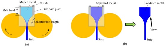
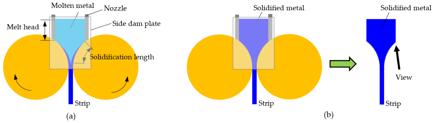
The VHSTRCA is shown in Figure 1a. The roll caster used in this study was designed and assembled by students in our laboratory at the Osaka Institute of Technology (Osaka City, Japan). The rotating rolls were stopped, and the molten metal was allowed to solidify. This process is referred to as a roll-stop in this study. A schematic diagram of the roll-stop and the solidified metal is shown in Figure 1b. The roll-stop was conducted to investigate the condition of the molten metal at the nozzle tip. The diameter and width of the copper rolls were 300 and 50 mm, respectively. The rolls were not equipped with cooling systems and were cooled naturally. Flat and grooved rolls were used, and the roll speed was 60 m/min. The solidification length and melt head were both 100 mm. The molten metal was poured through a launder into a pool formed by the nozzles and side dam plates. A 2.3 mm thick mild steel plate was covered with a 2 mm thick insulating sheet. The gap between the nozzle and roll surface was 0.5 mm. The side dam plates were made from the same mild steel plate and insulating sheet and contacted the sides of the rolls. One roll was movable and was pushed by coil springs, whereas the other roll was fixed. The initial roll loads were set at 3 or 20 N/mm using the coil springs. The initial roll-to-roll gap was 1 mm, and the roll gap varied with the strip thickness. The roll surfaces were buff polished.
Figure 1.
Schematic diagram of vertical-type high-speed twin roll caster for aluminum alloy. (a) Vertical-type high-speed twin roll caste; (b) Roll-stop and investigation of solidified metal.
The chemical composition of the aluminum alloy used in this study is summarized in Table 1. This aluminum alloy was prepared as a model recycled aluminum alloy made from A383 and 6022 alloys. Given that the Si content of this alloy was approximately 3 mass%, the alloy likely had a quasi-solidus line. The casting temperature of the aluminum alloy was 645 °C. Penetrant testing was conducted on the cast and cold-rolled strips to investigate the occurrence of surface cracks.
Table 1.
Chemical composition of aluminum alloy (mass%).
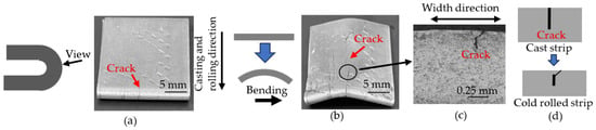
The cast strip was homogenized at 400 °C for 1 h, cold-rolled down to a thickness of 1 mm, and annealed at 400 °C for 1 h, after which deep drawing was conducted. Cold rolling was conducted in the casting direction. The diameter of the blank used for deep drawing was 50 mm. The punch diameter and blank holding force of the deep drawing were 32 mm and 1.2 kN, respectively. A 180° bending test was conducted on a cold-rolled and annealed strip cast using the flat roll to investigate the occurrence of cracks in the casting direction. The bending direction was perpendicular to the casting direction. A schematic diagram of the bending test is shown in Figure 2.
Figure 2.
Schematic diagram of 180° bending test of cold-rolled and annealed 1 mm thickness.
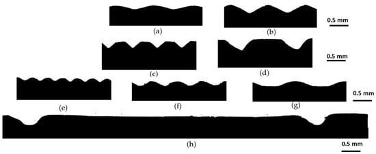
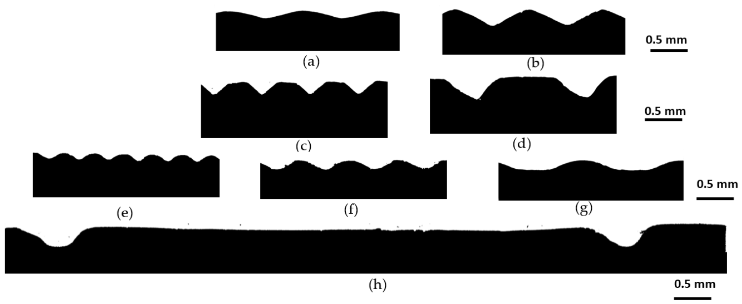
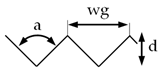
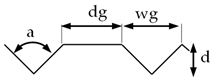
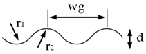
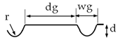
Grooves were formed by knurling the roll surface. The groove shapes on the roll surface are shown in Figure 3. The shapes, dimensions, and spacing of the grooves, which were expected to affect the strip surface, were selected, and the effect of the grooves on the strip surface was investigated. The groove shapes shown in Figure 3 were measured using replicas of the roll surface that were made using silicone putty (Exafine putty type, GC Dental Products Corp., Kasugai City, Aichi, Japan), and dimensions are shown in Table 2. In Figure 3a,b, sharp grooves are formed in a continuous pattern. In Figure 3c,d, flat areas are present between the sharp grooves. In Figure 3e–g, the grooves and protrusions are curved. In Figure 3h, the distance between the grooves is wide.
Figure 3.
Shapes of grooves used in this study. Dimensions of (a–h) are shown in Table 2.
Table 2.
Dimensions of grooves from Figure 3a–h.
Photographs for visual inspection of the surfaces of the cast strips were taken with a camera (COOLPIX W300, NIKON, Shinagawa, Tokyo, Japan). Cross sections near the surfaces were observed using a microscope to investigate the surface morphology (ECLIPSE LV150N, NIKON, Shinagawa, Tokyo, Japan).
Three casting trials were conducted for each groove shape. The steady-state region, approximately 3 m long, was examined after excluding the first 1 m and final 1.5 m of each strip. Because visual inspection showed no differences among the three strips, one strip was randomly selected, and a 200 mm section was cut from it for cross-sectional observation and cold rolling. For cold rolling, the central section along the strip length was selected as representative. Deep drawing tests were performed three times on the rolled sheet. The specimen showing the second-best condition among the three tests was selected as representative.
3. Results and Discussion
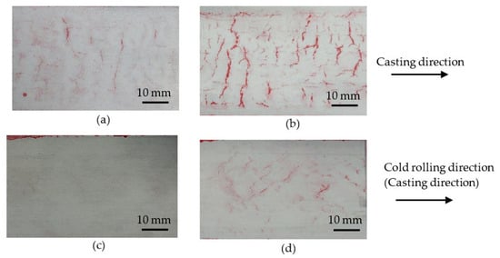
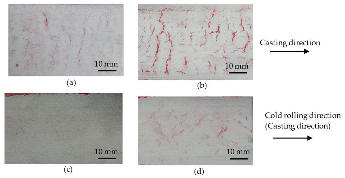
The surfaces of strips cast using flat rolls and of cold-rolled strips after penetrant testing are shown in Figure 4, with red areas indicating surface cracks. The roll loads were 3 and 20 N/mm. The cracks in cast strips produced at a roll load of 20 N/mm were more severe than those produced at a roll load of 3 N/mm, as judged by crack width. This indicates that roll load is one cause of surface cracks and that the cracks may occur at the roll bite. The number of surface cracks in the width direction appears to be greater than that in other directions, and these cracks are more severe. The surface of the cast strip may be deformed in the casting direction at the roll bite, and width-direction cracks may be caused by tensile stress in the casting direction. The cracks in cold-rolled strips made from strips cast at a roll load of 20 N/mm were more severe than those made from strips cast at a roll load of 3 N/mm, as judged by the number of cracks. Cold rolling appeared to reduce the cracks in the cast strips. The width-direction cracks appeared to have been eliminated, whereas diagonal cracks remained in the cold-rolled strips. It is not clear whether the diagonal cracks developed from the width-direction cracks or were caused by cold rolling.
Figure 4.
Surfaces of cast and cold-rolled strips, cast using a flat roll, after penetrant testing. Red areas indicate surface cracks. Roll speed of casting was 60 m/min. (a,b) are cast strips. Roll loads of (a,b) are 3 N/mm and 20 N/mm, respectively. (c,d) were cold-rolled from (a,b), respectively.
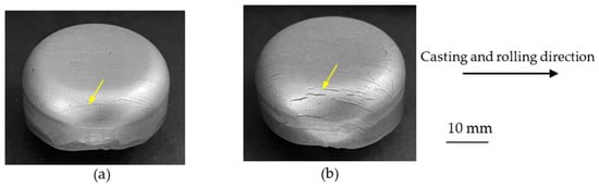
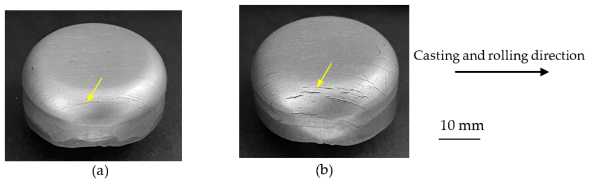
Deep drawing was conducted on cold-rolled strips with a thickness of 1 mm. The results are shown in Figure 5. Cracks were present in the deep-drawing cups, and the cracks in cups made from strip cast at a roll load of 20 N/mm were more severe than those in cups made from strip cast at a roll load of 3 N/mm. Width-direction cracks were severe in the cast strip, whereas diagonal cracks were severe in the cold-rolled strip. In the deep drawn cup, cracks in the casting and rolling directions were more severe. For the cast and cold-rolled strips, penetrant testing was used to detect severe cracks in the casting and rolling directions that formed during a bending test.
Figure 5.
Result of deep drawing of cold-rolled strips. The strips used for cold rolling were cast using the flat roll. Arrows show cracks. Roll speed was 60 m/min. Roll loads of (a,b) were 3 N/mm and 20 N/mm, respectively.
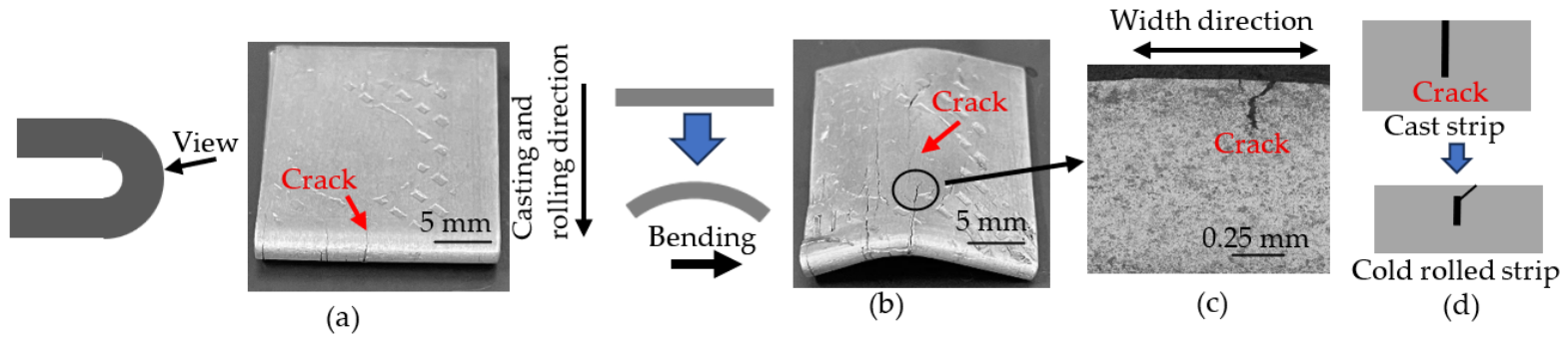
The cold-rolled strip was bent, and its surfaces and cross sections were observed, as shown in Figure 6. A crack, which had not been confirmed before bending, occurred on the outer surface after bending perpendicular to the casting and rolling directions, as shown in Figure 6a. The strip shown in Figure 6a was bent perpendicular to the width direction, as shown in Figure 6b. Cracks parallel to the casting and rolling directions occurred. The cross section near a crack in Figure 6b is shown in Figure 6c. The crack near the surface appeared to have been depressed and closed by cold rolling, as shown in Figure 6d. This closed crack might not have been detectable by penetrant testing. Furthermore, it was not bonded and might have reopened during deep drawing or bending. At present, it is not clear at what stage the cracks parallel to the casting and rolling directions formed.
Figure 6.
Bending of cold-rolled and annealed strips. The strip was cast using the flat roll. Roll speed was 60 m/min. Roll load was 3 N/mm. (a) Bending perpendicular to the casting and cold rolling direction. (b) Bending perpendicular to width direction of (a,c). Cross section near cracks in (b,d). Schematic diagram showing crack deformation near the surface after cold rolling.
The strip-width-direction cracks appeared to decrease. These cracks might have been reduced by the process shown in Figure 7, in which the strip became thinner and longer during cold rolling. The depth of the width-direction cracks was predicted to decrease, and their width to increase during cold rolling. Although this may have led to the elimination of the width-direction cracks, evidence of this process could not be identified in the present study.
Figure 7.
Schematic diagram showing expected improvement of the cracks in the width direction after rolling.
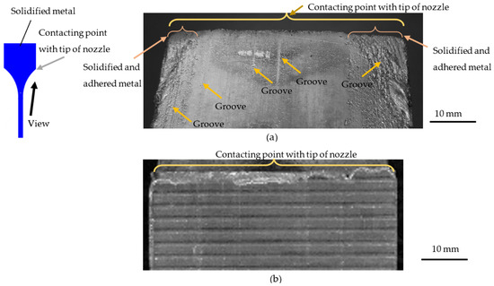
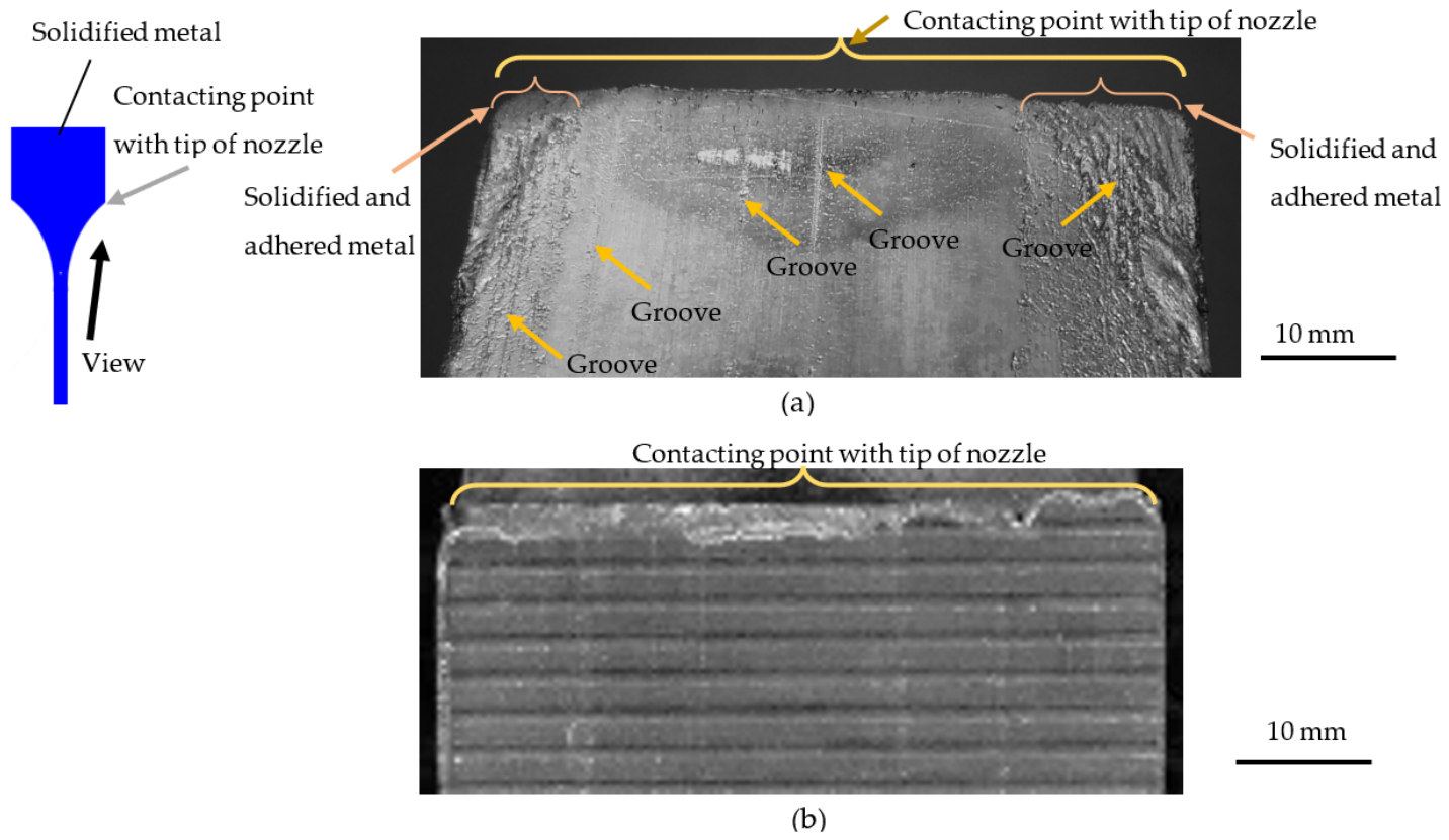
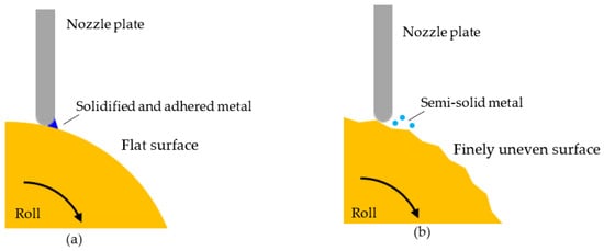
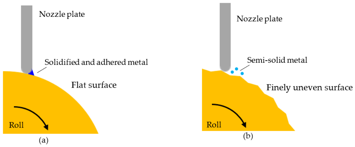
A roll-stop experiment was conducted using flat and grooved rolls. The rolls were stopped, the molten metal between the rolls was allowed to solidify, and the condition of the solidified metal in contact with the rolls was observed, as shown in Figure 8. When flat rolls were used, solidified metal adhered at both edges of the metal obtained in the roll-stop experiment, as shown in Figure 8a. When grooved rolls were used, adhered solidified metal was not observed, as shown in Figure 8b. Grooves in the casting direction were present both in areas with adhered metal and in areas without adhered metal. These grooves may develop into cracks in the casting direction. Moreover, the condition of the molten or solidifying metal at the nozzle tip might affect crack occurrence. If solidifying metal forms at the nozzle tip when a flat roll is used, as shown in Figure 9a, a roll with a finely uneven surface may affect the contact between the molten metal and the nozzle tip and the formation of solidifying metal, as shown in Figure 9b. Thus, a roll with a finely uneven surface may eliminate cracks, especially those in the casting direction. To confirm this, a surface with width-direction grooves was adopted as the finely uneven surface, and the rolls with width-direction grooves shown in Figure 3 were tested.
Figure 8.
Solidified metal near tip of nozzle after roll-stopping. Roll speed was 60 m/min. Roll load was 3 N/mm. (a) Flat roll, (b) grooved roll (Figure 3d).
Figure 9.
Schematic diagram showing behavior of metal near the nozzle tip. (a) Flat roll; metal solidified and adhered to the nozzle tip. (b) Roll with finely uneven surface; solidified metal did not adhere to the nozzle tip.
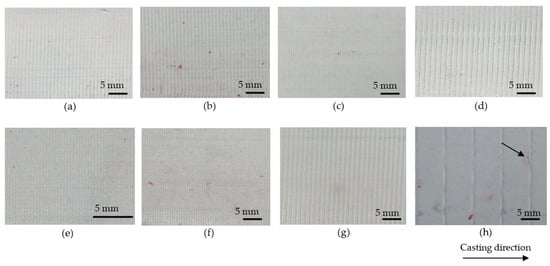
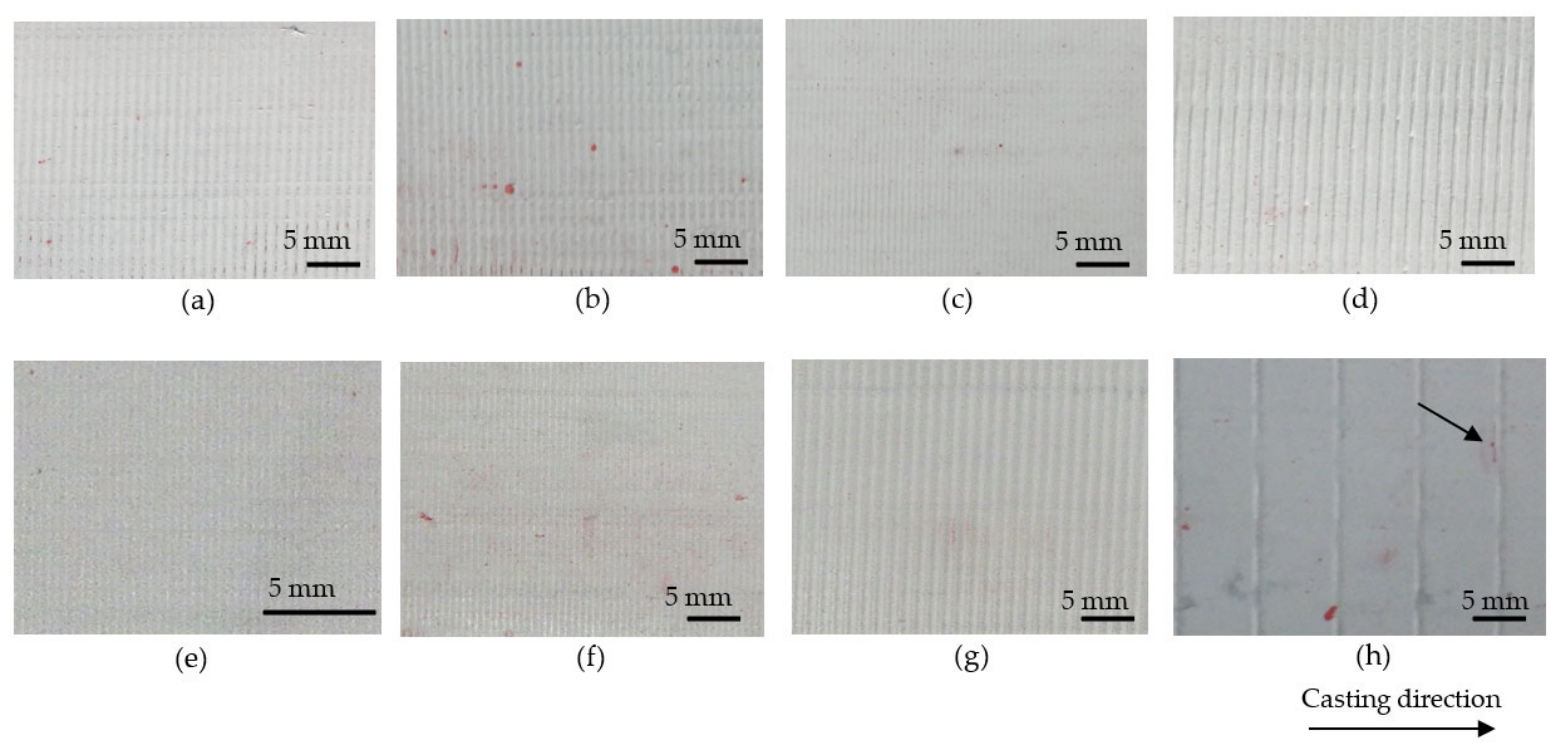
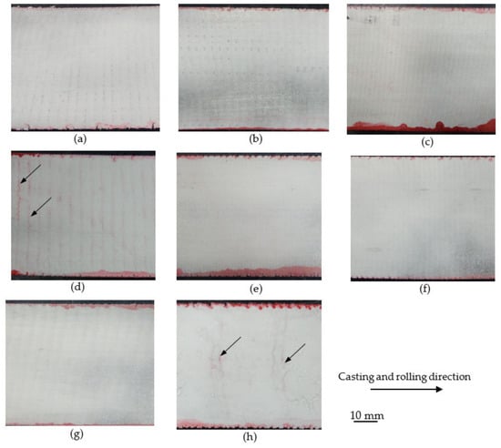
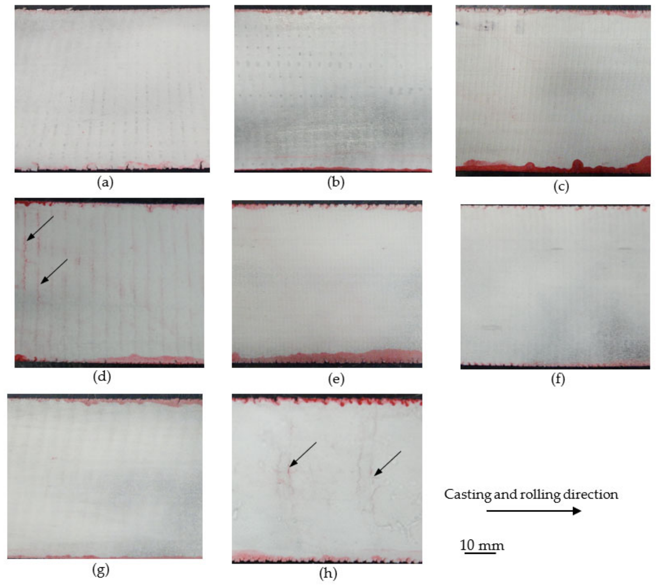
The surfaces of strips cast using the grooved rolls shown in Figure 3 after penetrant testing are presented in Figure 10. Panels (a,h) in Figure 10 correspond to panels (a–h) in Figure 3. The roll speed and roll load were set at 60 m/min and 3 N/mm, respectively. The grooves affected the surfaces of the cast strips, and protrusions formed on the strip surfaces. The protrusions on the cast-strip surfaces appeared to be affected by the groove shapes. Cracks such as those in Figure 4 did not occur on the surfaces of the strips cast using grooved rolls. In Figure 10h, a width-direction crack was observed, but it was not as severe as those in Figure 4. This crack is indicated by an arrow in Figure 10h. Figure 10 shows that width-direction grooves are effective in eliminating surface cracks. When the distance between the grooves is large, cracks may occur adjacent to the grooves, as shown in Figure 10h. Differences among the effects of the groove shapes on the elimination of surface cracks are not clear from the results shown in Figure 10.
Figure 10.
Surfaces of penetrant-tested cast strip cast using grooved rolls. (a–h) match the respective patterns shown in Figure 3. The arrow indicates a surface crack. Roll speed was 60 m/min. Roll load was 3 N/mm.
The solidified and adhered metal shown in Figure 8 was not observed when the grooved roll was used. The grooves affected the solidification of the molten metal at the nozzle tip. In Figure 3h, the distance between the grooves was 7 mm, which was greater than that for the other groove shapes. Assuming that each groove on the rotating roll scoops away molten metal and thereby prevents solidified metal from adhering, the scraping frequency was calculated by dividing the roll speed of 60 m/min (1 m/s) by the 7 mm groove spacing. The resulting frequency was approximately 143 Hz. This frequency may be sufficient to prevent metal from adhering to the nozzle tip; however, the minimum effective scraping frequency remains unclear. Moreover, the grooves were predicted to prevent crack occurrence at the roll bite. Before strip casting using the grooved roll, the grooves were expected to promote crack occurrence, especially in the width direction. Instead, the grooves prevented crack occurrence at the roll bite. Deformation of the solidified layer at the roll bite might have been prevented, and cracks did not occur.
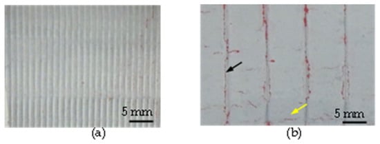
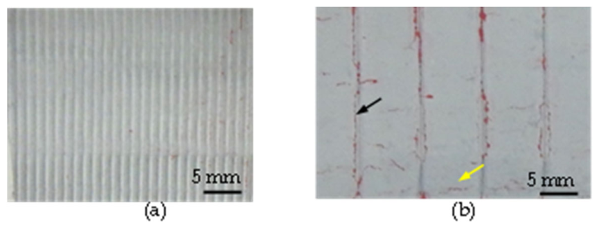
To evaluate the effectiveness of the width-direction grooves, Figure 11 shows the results of penetrant testing on strips cast using the grooved rolls shown in Figure 3g,h at a roll load of 20 N/mm. Comparison with Figure 4b, which shows the surface condition of a strip cast using flat rolls, indicates that crack occurrence was suppressed in the strips shown in Figure 11. Two types of cracks were present in Figure 11b: casting-direction cracks, indicated by yellow arrows, and width-direction cracks beside the protrusions, indicated by black arrows. The cracks beside the protrusions were caused by the grooves. When the distance between the grooves is large and the roll load increases, casting-direction cracks may not be eliminated.
Figure 11.
Surfaces of penetrant-tested cast strip cast using grooved rolls. (a,b) match the respective patterns shown in Figure 3g,h. Red areas indicate surface cracks. The black arrow indicates a crack beside a protrusion. The yellow arrow indicates a casting direction crack. Roll speed was 60 m/min. Roll load was 20 N/mm.
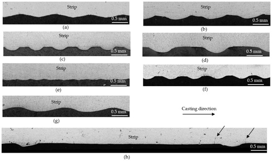
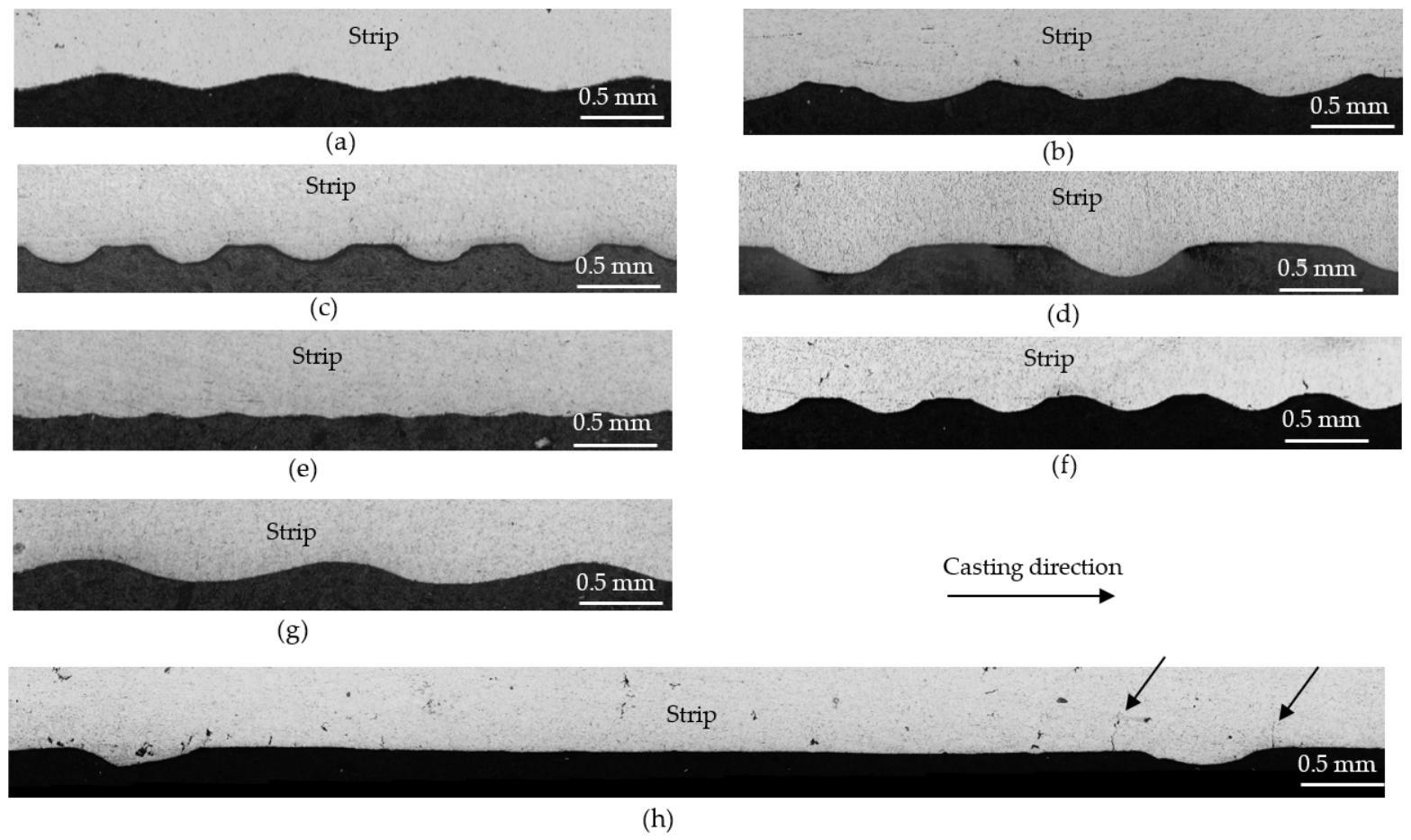
Cross sections of strips cast using the grooved rolls are shown in Figure 12. Panels (a) to (h) in Figure 12 correspond to panels (a) to (h) in Figure 3 and Figure 10. Protrusions formed on the surfaces of the cast strips, and the shapes of these protrusions were affected by the groove shapes. The protrusion shapes in Figure 12a,f,g appear to be almost the same as the roll groove shapes. In Figure 12b–e,h, the molten metal appears not to have completely filled the grooves. In Figure 12, when the groove width, “wg,” and groove-tip angle, “a,” were small, the molten metal did not fill the grooves. This may indicate that the molten metal could not enter the grooves, but grooves with arc-shaped tips were filled. These results suggest that whether the grooves are filled does not affect the occurrence of surface cracks. The protrusion in Figure 12e was very small, likely indicating that the groove had very little effect on the molten metal at the nozzle tip. However, the solidified and adhered metal shown in Figure 8 was not observed in this case. This may mean that the small groove helped prevent solidifying metal from adhering to the nozzle tip. Crack occurrence at the roll bite could also be prevented, which may indicate that the small groove prevented deformation of the strip surface. As shown in Figure 12h, cracks occurred at the bottom of the protrusion, but their cause is not clear.
Annealing, cold rolling, and penetrant testing were conducted on the strips shown in Figure 10, and the results are shown in Figure 13. Panels (a) to (h) in Figure 13 correspond to panels (a) to (h) in Figure 3, Figure 10 and Figure 12.
Traces of the grooves remained after cold rolling, and as the protrusion height increased, the protrusion trace became clearer. Moreover, the distance between the protrusions increased during cold rolling. In Figure 13, except for panels (d) and (h), cracks did not occur during cold rolling. Only in panel (d) did the protrusions cause cracks during cold rolling, for which there are two possible reasons. First, a crack or weak area may have been present near a protrusion in the cast strip but may not have been detected in Figure 10 and Figure 12. Second, the crack may have occurred when the protrusion was compressed during cold rolling. The protrusion in panel (d) was higher than those in the other panels. Deformation near the base of a protrusion may increase with protrusion height; therefore, deformation near the base of the protrusion in panel (d) may have been greater than in the other panels. As a result, a crack occurred only in panel (d). Cracks are visible in Figure 10h, and the cracks became longer in the width direction in Figure 13h. There are two possible causes of the cracks shown in panel (h). First, a crack may have formed during cold rolling. Second, a preexisting fine crack may have enlarged during cold rolling, as suggested by Figure 12h. The protrusion traces could not be eliminated by cold rolling.
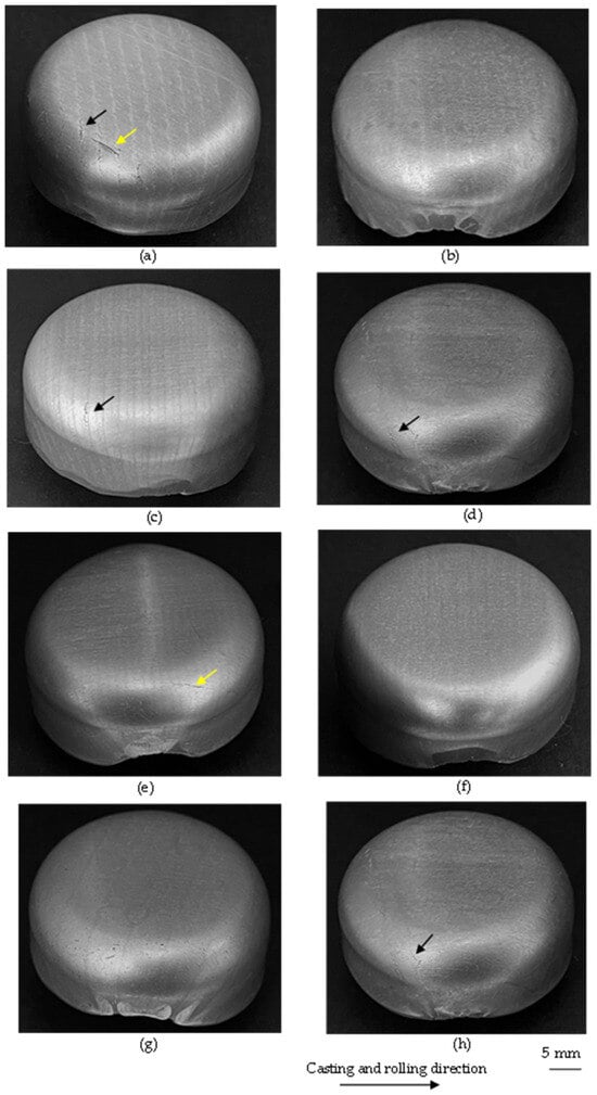
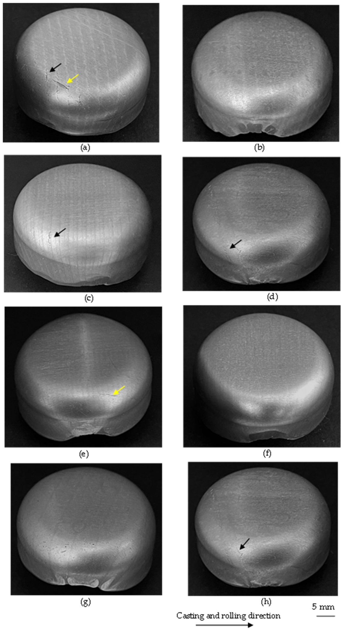
Deep drawing was conducted on the strips shown in Figure 13, and the results are shown in Figure 14. Panels (a) to (h) in Figure 14 correspond to those in Figure 3 and Figure 13. In Figure 14a,c,d,h, cracks occurred at the positions of the groove traces.
Figure 14.
Result of deep drawing of cold-rolled strips. Roll speed was 60 m/min. Roll load: 3 N/mm. Black arrows show cracks in the protrusion (groove) direction. Yellow arrow shows cracks in the casting and cold rolling direction. (a–h) Match the respective panels in Figure 10, Figure 12 and Figure 13.
Under conditions other than those shown in Figure 14a,c,d,h, cracks did not occur along the groove traces. The results shown in Figure 13 suggest a tendency for cracks to occur along the protrusion traces when the traces remain clear after cold rolling. In other words, cracks tend to occur along large protrusions. Thus, when the grooves are large, cracks occur along the protrusions. These cracks originated during cold rolling rather than during casting, although their positions were associated with the groove traces. Cracks in the casting direction are shown in Figure 14a,e. When the grooves are too small, cracks occur in the casting direction; therefore, grooves that are too small will not eliminate casting-direction cracks. By contrast, the casting-direction cracks originated during roll casting. When the protrusions are higher than 0.2 mm, cracks occur along the protrusions, but casting-direction cracks are eliminated. When the protrusions are lower than 0.03 mm, casting-direction cracks occur, but their number and severity decrease. Ultimately, crack occurrence is considered to be determined not by the groove width or depth alone but by a combination of the two. The grooves shown in Figure 3b,f,g are suitable for eliminating cracks in the groove direction and in the casting and rolling directions in the deep drawn cups. Traces of the grooves remained after deep drawing. The trace in Figure 14f appears fainter than those in Figure 14b,g.
Table 3 summarizes whether cracks occurred during each process. Rows (a) to (h) correspond to panels (a) to (h) in Figure 3.
Table 3.
Occurrence of crack at each process.
4. Conclusions
- (1)
- Using a high-speed twin-roll caster for aluminum alloy, the effect of eight types of grooves in the width direction of the roll on preventing cracks was investigated using cast strips, cold-rolled strips, and cups produced by deep drawing. The strips were cast at a roll speed of 60 m/min and a roll load of 3 N/mm.
- (2)
- In the cast strip, there were two areas where cracks occurred: the nozzle tip and the roll bite.
- (3)
- Protrusions were formed on the cast strip by using grooved rolls. The protrusion size was affected by the groove size.
- (4)
- When the groove width and depth were 0.4 and 0.1 mm, respectively, the protrusion height was less than 0.03 mm. This condition did not prevent cracks at the nozzle tip but helped prevent cracks at the roll bite, indicating that this groove may be too small.
- (5)
- When the groove width and depth were 0.7 and 0.3 mm, respectively, the protrusion height was greater than 0.2 mm. This condition helped prevent cracks at both the nozzle tip and the roll bite. However, cracks occurred along the protrusions, indicating that this groove may be too large.
- (6)
- The protrusion traces became less distinct after cold rolling when the protrusions were smaller; however, they could not be completely eliminated.
- (7)
- The appropriate groove shapes were determined based on the deep drawing results. Traces of the grooves remained after deep drawing.
Author Contributions
Conceptualization, T.H. and K.M.; methodology, T.H. and R.K.; validation, T.H., R.K., and K.M.; formal analysis, T.H., R.K., and K.M.; investigation, T.H., R.K. and K.M.; resources, T.H. and K.M.; data curation, X T.H., R.K., and K.M.; writing—original draft preparation, T.H. and R.K.; writing—review and editing, T.H. and K.M.; visualization, T.H., R.K., and K.M.; supervision, T.H.; project administration, K.M.; funding acquisition, K.M. All authors have read and agreed to the published version of the manuscript.
Funding
This paper is based on results obtained from a project, JPNP21003, subsidized by the New Energy and Industrial Technology Development Organization (NEDO).
Data Availability Statement
The original contributions presented in this study are included in the article. Further inquiries can be directed to the corresponding author.
Conflicts of Interest
Author Kazuharu Masada was employed by the company Kobe Steel, Ltd. The remaining authors declare that the research was conducted in the absence of any commercial or financial relationships that could be construed as a potential conflict of interest.
References
- Dündar, K.; Altuncu, E.; Birbaşa, O. Deep drawability of Al-Mg alloys produced by twin roll continuous casting method: Investigation of microstructure and mechanical properties. Metals 2024, 14, 1365. [Google Scholar] [CrossRef] [Scilit]
- Qian, A.; Xu, Z.; Song, B.; Ma, Y.; Jia, P. Effect of pulse electric current on macro-segregation during twin-roll casting of Al-Mg-Si alloys. Mater. Trans. 2025, 66, 878–887. [Google Scholar] [CrossRef] [Scilit]
- Kim, M.S.; Kim, J. Metallurgical method of determining heat transfer coefficient in simulations of twin-roll casting. Metals 2024, 14, 358. [Google Scholar] [CrossRef] [Scilit]
- Uiimann, M.; Stirl, M.; Prahl, U. Twin-roll casting defects in light metals. J. Mater. Sci. 2024, 59, 19003–19022. [Google Scholar] [CrossRef] [Scilit]
- Li, Y.; He, C.; Li, J.; Wang, Z.; Wu, D.; Xu, G. A novel approach to improve the microstructure and mechanical properties of al–mg–Si aluminum alloys during twin-roll casting. Materials 2020, 13, 1713. [Google Scholar] [CrossRef] [Scilit] [PubMed]
- Matsushita, T.; Nakayama, K.; Fukase, H.; Osada, S. Development and Commercialization of Twin Roll Strip Caster. IHI Eng. Rev. 2009, 42, 1–9. [Google Scholar]
- Yasunaka, H.; Taniguchi, K.; Kokita, M.; Inoue, T. Surface Quality of Stainless Steel Type 304 Cast by Twin-roll Type Strip Caster. Tetsu Hagane 1994, 80, 717–722. [Google Scholar] [CrossRef] [Scilit] [PubMed]
- Büchner, A.R.; Zimmermann, H. Cracking of phenomena in twin roll strip casting of steel. Steel Res. 2002, 73, 327–331. [Google Scholar] [CrossRef] [Scilit]
- Legrand, H.; Albrecht-Früh, U.; Flick, A. Eurostrip—A quanum leap for hot band production via the trip casting technology. Met. Ital. 2002, 94, 54–59. [Google Scholar]
- Haga, T.; Ikawa, M.; Kumai, S. A high-speed twin roll caster for aluminum alloy thin Strip. Trans. Mater. Res. Soc. Jpn. 2004, 29, 1823–1828. [Google Scholar]
- Kim, M.S.; Kim, H.W.; Kim, S.H.; Kumai, S. Role of Roll Separating Force in High-Speed Twin-Roll Casting of Aluminum Alloys. Metals 2019, 9, 645. [Google Scholar] [CrossRef] [Scilit]
- Kitaoka, Y. Castability of aluminum casting alloys. J. Jpn. Inst. Light Met. 1991, 41, 365–372. [Google Scholar] [CrossRef] [Scilit]
- Haga, T. Cracking on semisolid condition Al alloy strip during high speed roll casting. In Proceedings of the 2026 Japanese Spring Conference for the Technology of Plasticity, Hamamatsu City, Japan, 19–21 March 2026; pp. 81–82. [Google Scholar]
- Haga, T.; Hirooka, K.; Watari, H.; Kumai, S. Grooved roll for a high speed twin roll caster. Arch. Mater. Sci. Eng. 2008, 30, 117–120. [Google Scholar]
- Kim, M.S.; Kumai, S. Solidification structure and casting defects in high- speed twin-54-10st Al-2 mass %Si ally strip. Mater. Trans. 2013, 54, 1930–1937. [Google Scholar] [CrossRef] [Scilit]
- Choo, D.K.; Lee, S.; Moon, H.K.; Kang, T. Analysys and prevention of cracking during strip casting of AISI304 stainless steel. Metall. Mater. Trans. A 2001, 32, 2249–2258. [Google Scholar] [CrossRef] [Scilit]





Disclaimer/Publisher’s Note: The statements, opinions and data contained in all publications are solely those of the individual author(s) and contributor(s) and not of MDPI and/or the editor(s). MDPI and/or the editor(s) disclaim responsibility for any injury to people or property resulting from any ideas, methods, instructions or products referred to in the content. |
© 2026 by the authors. Licensee MDPI, Basel, Switzerland. This article is an open access article distributed under the terms and conditions of the Creative Commons Attribution (CC BY) license.