


Abstract
Molecular dynamics simulations were performed to examine the temperature-dependent nanoindentation response of aluminum substrates coated with amorphous or crystalline equiatomic FeNiCrCo layers. The study extends our previous 300 K baseline analysis of the same model system by comparing deformation at 300 and 600 K and by examining the spatial redistribution of local kinetic energy and local nonequilibrium kinetic-temperature indicators during loading and unloading. A spherical virtual indenter with a radius of 30 Å was driven to maximum penetration depths of 35 and 65 Å, representing predominantly coating-controlled deformation and a regime involving the coating–substrate interface and aluminum substrate, respectively. At both temperatures, the crystalline coating exhibited higher indentation resistance and serrated force–depth responses associated with intermittent lattice-mediated plasticity, whereas the amorphous coating showed lower force levels and smoother deformation through distributed local atomic rearrangements. Increasing the temperature from 300 to 600 K enlarged the deformation-affected region and promoted a greater involvement of the interface and Al substrate. Nevertheless, the spatial character of the response remained structure-dependent: the crystalline coating retained a comparatively compact region of elevated local kinetic energy beneath the indenter, whereas the amorphous coating displayed a broader and more diffuse kinetic-energy perturbation. Adaptive common-neighbor analysis was used as a qualitative local-environment descriptor; therefore, structural labels are interpreted together with force–depth curves and atomistic configurations rather than as unique phase identifiers. The results identify temperature-dependent trends in deformation localization and energy redistribution for an idealized FeNiCrCo/Al model system. Because the simulations employ a finite periodic cell, a high indentation velocity, and an empirical potential, the findings are interpreted as qualitative atomistic trends and are not quantitatively extrapolated to experimental indentation conditions.
1. Introduction
High-entropy alloys (HEAs) represent a class of multicomponent metallic materials containing several principal elements in comparable concentrations [1,2,3,4,5]. Owing to the high level of chemical disorder and the specific features of interatomic interactions, such alloys can combine high strength, ductility, and thermal stability [6,7,8,9], which makes them promising for operation under intense mechanical and thermal loading.
One promising application of HEAs is the development of protective coatings that enhance the contact strength and durability of structural-material surfaces [10,11,12,13,14,15,16,17,18]. Such coatings are of particular interest for aluminum and its alloys, which, despite their low density, high specific strength, and good processability, exhibit relatively low hardness and a tendency to localized plastic deformation under contact loading [19]. Applying an HEA layer onto an Al substrate makes it possible to increase the resistance to indentation, reduce the depth of the plastic zone, and limit the development of defect structures in the substrate [20,21]. Atomistic studies of high-entropy-alloy coatings on aluminum substrates have also demonstrated that coating composition, local chemical disorder, interfacial structure, and loading conditions can substantially affect load transfer and the development of substrate defects. For example, Yang et al. used molecular dynamics simulations to investigate the mechanical and tribological behavior of an AlCoCrFe high-entropy-alloy coating on an aluminum substrate, highlighting the sensitivity of coating-mediated deformation to structural and interfacial factors [22]. More broadly, recent reviews emphasize that chemical short-range order in compositionally complex alloys can modify local structural stability, defect energetics, and mechanical response; it must therefore be considered when interpreting atomistic simulations of multicomponent metallic systems [23].
The mechanical response of HEA coatings is strongly affected by their structural state [8]. Crystalline coatings typically deform through dislocation slip, defect interactions, and, in some cases, twinning; these mechanisms are commonly associated with higher hardness and discontinuous plastic flow [19,24,25,26,27,28,29,30,31]. Recent atomistic and experimental analysis of CoNiV medium-entropy alloy fibers has further demonstrated that the interplay between dislocation-mediated plasticity and compositional/structural strengthening can govern the macroscopic deformation response of multicomponent alloys [32]. Amorphous structures, in contrast, lack long-range order and deform via local atomic rearrangements and activation of shear transformation zones, which leads to a smoother mechanical response and a different mode of stress relaxation. Therefore, a comparison of amorphous and crystalline states of the same coating is of interest for clarifying the mechanisms of load transfer in a coating/substrate system.
One of the most informative approaches to studying local mechanical properties of surface layers is indentation combined with molecular dynamics simulations. This approach makes it possible to follow the evolution of the atomic structure in the contact zone, analyze the nucleation and development of defects, and evaluate the contributions of the coating and substrate to the overall mechanical response of the system. For FeNiCrCo/Al-type systems, this is especially important because, at different indentation depths, deformation can be localized either mainly within the coating or propagate into the Al substrate with activation of dislocation and twinning mechanisms [33,34,35,36,37,38,39,40,41].
Temperature is an important factor in local contact deformation. An increase in temperature affects atomic mobility, the intensity of relaxation processes, and the conditions for activating plastic deformation. For crystalline HEAs, a temperature rise can facilitate dislocation nucleation and motion, whereas for amorphous structures it can modify the kinetics of shear transformation zones and the degree of homogeneity of plastic flow. Consequently, temperature governs not only the magnitude of the resistance to indentation but also the scenario of structural evolution in the coating/substrate system.
In recent years, considerable attention has been paid to amorphous, crystalline, and amorphous–crystalline HEA coatings capable of combining high load-bearing capacity with efficient redistribution of local stresses. Our previous 300 K study established the contrasting indentation responses of amorphous and crystalline FeNiCrCo coatings on Al, including the effects of Monte Carlo/molecular dynamics (MC/MD) pre-relaxation and indentation depth [42]. The present work addresses the more specific unresolved question of how increasing the temperature to 600 K modifies deformation morphology, coating–substrate load transfer, and the spatial distribution of local kinetic-energy signals in this established model system. In particular, the influence of temperature on the shape of the force–depth curves F(d), on the degree of involvement of the Al substrate in plastic deformation, and on the differences between the continuous flow of the amorphous layer and the discrete plasticity of the crystalline coating requires further clarification.
In this work, we extend the previously reported 300 K FeNiCrCo/Al nanoindentation baseline [42] by investigating the response of the same idealized bilayer system at 300 and 600 K. The aim is not to re-establish the general distinction between amorphous and crystalline FeNiCrCo coatings, but to determine whether their contrasting deformation modes persist under elevated-temperature conditions and how temperature modifies the spatially binned per-atom kinetic-energy signal under the prescribed thermostatting and indentation protocol, local nonequilibrium kinetic-temperature indicators, and residual structural changes. Two maximum indentation depths, 35 and 65 Å, are considered to distinguish a predominantly coating-controlled regime from a regime in which the interface and Al substrate are substantially involved. The conclusions are deliberately limited to qualitative atomistic trends for the selected potential, simulation cell, boundary conditions, and high-rate loading protocol.
2. Materials and Methods
2.1. Material of the Study and Simulation Model
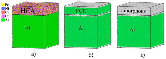
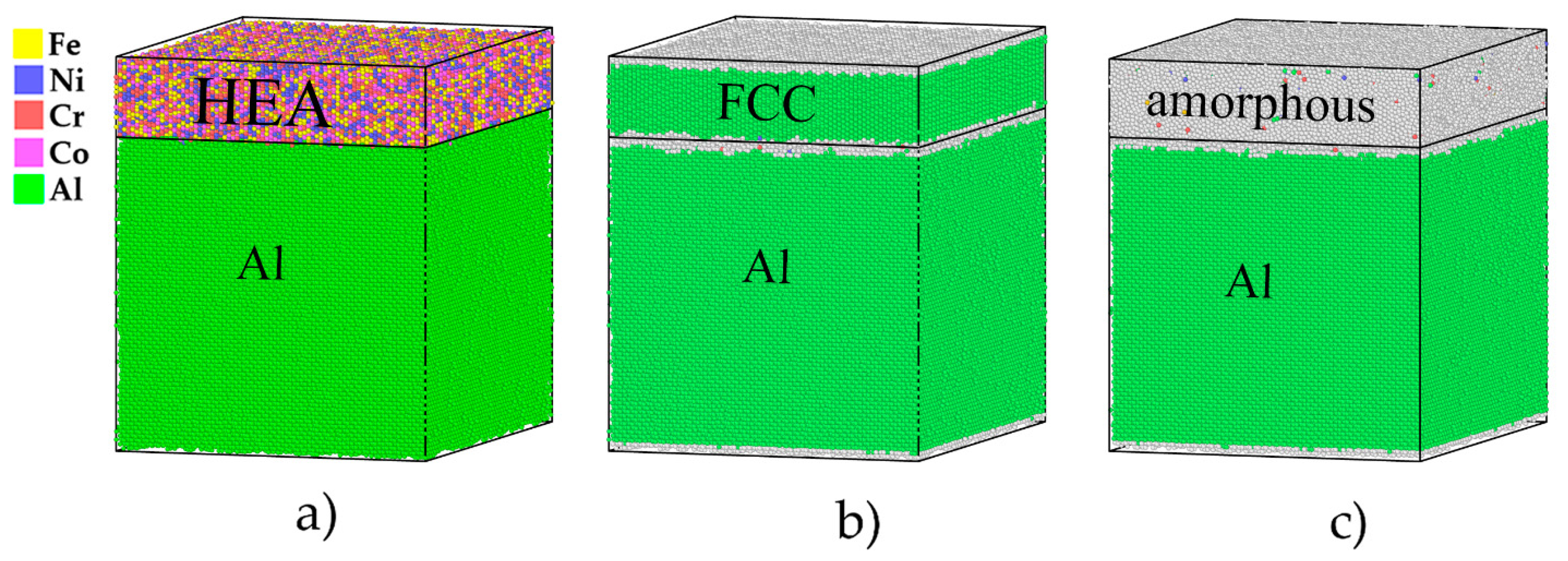
Molecular dynamics simulations were carried out using the LAMMPS package (version 29 Aug 2024) [43], while visualization and analysis of the atomic structure were performed in OVITO (version 3.5.4) [44]. Two bilayer models in the form of rectangular parallelepipeds were considered. Each model consisted of an aluminum substrate and a surface layer of the high-entropy alloy FeNiCrCo. In one case, the coating had a crystalline structure, whereas in the other it was amorphous. The simulation cell geometry and the initial configurations of the systems are shown in Figure 1.
Figure 1.
Initial structure of the FeNiCrCo/Al system: (a) simulation cell geometry, (b) crystalline Face-Centered Cubic (FCC) FeNiCrCo coating, (c) amorphous FeNiCrCo coating.
The dimensions of the Al substrate were 200 × 160 × 150 Å, and those of the FeNiCrCo surface layer were 200 × 160 × 40 Å [20,32,34]. The total number of atoms in the Al substrate was about 304,000, while the upper layer contained nearly 110,000 atoms. For aluminum, the crystallographic directions [100], [010], and [001] were oriented along the x, y, and z axes, respectively, and the crystalline lattice of the high-entropy alloy was oriented along [111,112] and [110]. The interatomic interactions in the system were described by an EAM-type potential previously applied to Fe–Ni–Cr–Co–Al alloys [45]. The employed embedded-atom method potential was selected because it was developed for the Fe–Ni–Cr–Co–Al chemical space and has been used to describe structural and mechanical trends in related multicomponent alloys [46,47,48]. Nevertheless, it remains an empirical potential, and its predictions for local chemical ordering, surface segregation, interface energetics, defect mobility, and high-temperature response are model-dependent. Recent machine-learned interatomic potentials may provide improved accuracy when trained against sufficiently broad first-principles datasets; however, they also require extensive validation for bulk, surface, interface, defect, and high-temperature configurations. Accordingly, the present results are interpreted as qualitative structure- and temperature-dependent trends within the selected EAM description, rather than as quantitatively transferable predictions for a specific experimental coating.
To obtain the amorphous coating, the initial FeNiCrCo structure was melted at 3400 K in an isothermal–isobaric NPT ensemble and subsequently cooled down to the required temperature with a cooling rate of 1012 K/s. Rapid quenching suppressed crystallization and led to the formation of an amorphous state of the coating [19,26]. In the case of the crystalline layer, Fe, Ni, Cr, and Co atoms were distributed randomly over the lattice sites, which corresponds to a chemically disordered high-entropy alloy model [49,50].
Before indentation, the system was energy-minimized and then subjected to the combined Monte Carlo/molecular dynamics (MC/MD) relaxation procedure described below. The purpose of this procedure was to reduce preparation-dependent nonequilibrium features and to allow chemical exchanges within the FeNiCrCo layer, thereby providing a more consistent initial state for comparing the amorphous and crystalline coatings. The phrase “reduced internal stresses” is used here only in a qualitative sense; the present study does not report a separate quantitative residual-stress analysis [49,50,51]. This approach ensured a consistent comparison between the amorphous and crystalline FeNiCrCo layers. In the present work, this scheme was retained, but the calculations were carried out for two temperature states of the system, 300 and 600 K.
The probability of atomic exchange during the MC stage was determined using the Metropolis criterion:
where E(i) and E(i+1) are the energies of the system before and after the atom swap, k is the Boltzmann constant, and T is the temperature. Trial swaps that lowered the energy were accepted unconditionally, whereas energetically unfavorable swaps were accepted with the probability given by Equation (1). This approach allows one to describe the transition of a multicomponent system into a thermodynamically more favorable state and is widely used for modeling chemical disorder and short-range order in HEAs [26,29]. During the initial construction and MC/MD relaxation stage, the combined system was equilibrated under periodic boundary conditions in all three directions. Before nanoindentation, the boundary condition in the surface-normal direction was changed to non-periodic shrink-wrapped, whereas periodicity was retained in the lateral x and y directions. Thus, indentation was conducted in a cell with lateral periodic boundaries and a free surface along z. The simulation time parameters and overall relaxation scheme were chosen so as to ensure comparability of the results for the crystalline and amorphous coatings [46,51].
2.2. Indentation Procedure
After completion of the MC/MD relaxation, the model was prepared for indentation using a spatially partitioned boundary and temperature-control scheme. The simulation cell was periodic in the lateral x and y directions and non-periodic in the surface-normal z direction during indentation. The FeNiCrCo coating was located at the top free surface, whereas the lower part of the Al substrate was divided into three regions along z. The bottom layer, extending from zlo + 10 Å to zlo + 10 Å and containing ~18,000 atoms, was constrained in the surface-normal direction by setting its z-component of force to zero. Thus, this layer prevented rigid-body displacement in the indentation direction while retaining in-plane atomic mobility. The adjacent layer from zlo to zlo + 20 Å contained 20,000 atoms and served as a thermostatted bath. It was integrated in the NVE ensemble and coupled to a Langevin thermostat at the target temperature, with a damping parameter of 0.01 ps. The remaining upper region, containing ~375,000 atoms, was integrated in the NVE ensemble and maintained near the target temperature using velocity rescaling every timestep with a temperature relaxation parameter of 0.01 ps. The temperature-control protocol was retained during both loading and unloading. Therefore, the simulations should be understood as mechanically driven atomistic indentation calculations performed with spatially partitioned thermostatting rather than as strictly microcanonical indentation trajectories. The contact region was not treated as a separate unthermostatted subsystem; consequently, local kinetic-energy fields are interpreted conservatively as comparative indicators obtained under the same thermal-control protocol, not as direct measurements of adiabatic heat generation.
Before indentation, the system was equilibrated for 5000 steps using a timestep of 0.5 fs. The global temperature drift during the complete loading–unloading sequence was not retained as a separate output in the archived dataset. This limitation is stated explicitly below. The target temperatures of 300 and 600 K were maintained by the prescribed thermostatting scheme, but no quantitative global-temperature-drift values are reported. Indentation was performed by a spherical virtual indenter with a radius of 30 Å that moved along the z-axis with a constant velocity of 20 m/s [26,39]. The high indentation velocity of 20 m/s was selected to make the atomistic deformation process accessible on MD time scales [35,37,38,39,40]. This velocity is much higher than experimental indentation velocities. Therefore, the results are used to compare structural states under one common atomistic loading protocol and are not interpreted as direct quantitative predictions of experimental-rate hardness, modulus, or dissipated heat.
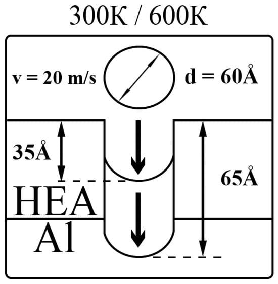
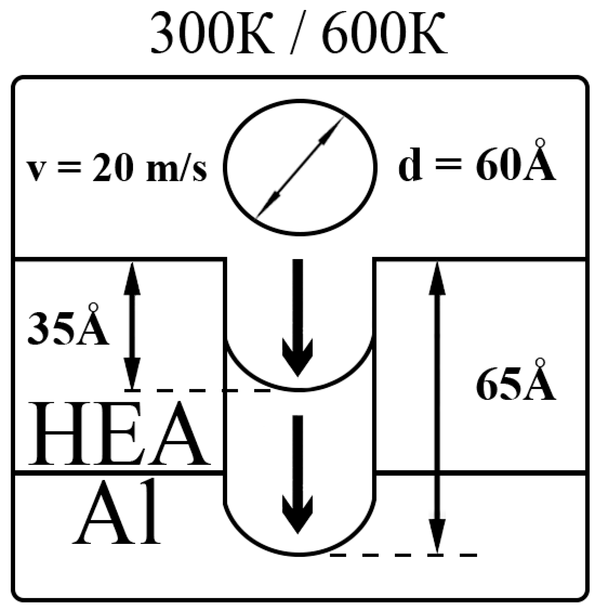
The scheme of the two indentation regimes considered is shown in Figure 2.
Figure 2.
Schematic representation of the indentation process for the FeNiCrCo/Al system at T = 300 and 600 K (maximum indentation depths d = 35 and 65 Å).
Indentation was carried out at two temperatures, 300 and 600 K. For each temperature, two types of coatings were examined, amorphous and crystalline, which provided a direct comparison of the influence of the structural state of the surface layer on the deformation behavior [52,53,54,55,56]. The interaction force between the indenter and atoms was described by a standard repulsive potential that depends on the distance between an atom and the indenter surface [25]. In analyzing the mechanical response, primary attention was paid to the dependence of the indentation force on the penetration depth of the indenter, F(d), since this curve makes it possible to distinguish between the elastic and plastic stages of loading and to evaluate the resistance of the system to local indentation [34,35,40]. The slope of the initial part of the F(d) curve characterizes the stiffness of the system response and is related to its effective resistance to elastic deformation. Abrupt force drops, pronounced changes in slope, or recurrent serrations in the force–depth curve may indicate discrete structural rearrangements and the onset of plastic events; these interpretations were verified by the corresponding atomistic configurations.
Two maximum indentation depths were considered: 35 and 65 Å. In the first case, the indenter did not reach the FeNiCrCo/Al interface, which made it possible to analyze mainly the mechanical behavior of the coating itself. In the second case, the depth of 65 Å ensured that the indenter penetrated through the entire HEA layer and involved the Al substrate in deformation. This separation makes it possible to study the contribution of the surface layer and the response of the coating/substrate system individually as an integrated composite [57]. To interpret the results, the force–depth curves, the change in potential energy, and the evolution of the local atomic structure in the coating and the substrate were analyzed. Local atomic environments were analyzed using the adaptive common-neighbor analysis (a-CNA) method implemented in OVITO [58]. In this approach, the neighbor cutoff is determined adaptively from the local atomic environment rather than being imposed as a single fixed global cutoff. The OVITO implementation was used with its automatic variable-cutoff determination. The resulting FCC, Hexagonal Close-Packed (HCP), Body-Centered Cubic (BCC), and “other” labels were treated as qualitative local-environment descriptors. In particular, atoms assigned to the “other” category in the chemically disordered FeNiCrCo coating or in highly strained regions were not interpreted automatically as a distinct amorphous phase or as deformation-induced defects, since local chemical disorder, thermal motion, strain, free-surface effects, and irreversible rearrangement may all affect the classification [59].
For reference, nanoindentation simulations were also performed for a bare Al substrate using the same cell dimensions, crystallographic orientation, boundary conditions, indenter radius, indentation velocity, maximum depths, and thermal protocol as in the coated systems. All presented results are averaged over three independent simulation runs to minimize the influence of thermal fluctuations and initial configuration variations.
2.3. Spatially Binned Kinetic-Energy Fields
Local kinetic-energy fields were evaluated by spatial binning of the per-atom kinetic-energy data in OVITO [60]. Two-dimensional maps were constructed on a 40 × 40 grid in the analyzed cross-sectional plane, corresponding to bin dimensions of approximately 5.08 × 5.15 Å2. One-dimensional profiles along the surface-normal direction were obtained using 40 bins of width approximately 5.13 Å. Within each bin, the mean per-atom kinetic energy was calculated using OVITO’s Mean reduction operation; therefore, the values were normalized by the local atom count.
The maps and profiles were calculated from individual instantaneous snapshots at the selected stages before indentation, at maximum penetration, and after unloading. No time averaging was performed. In addition, the local center-of-mass velocity was not subtracted in the original post-processing workflow. Consequently, these fields contain both thermal atomic motion and any collective/streaming contribution associated with the driven indentation process. They are therefore referred to throughout this work as spatially binned local kinetic-energy distributions, rather than local thermodynamic temperature fields or direct maps of heat dissipation.
The same binning, normalization, snapshot selection, and visualization protocol was applied to all systems. Accordingly, the maps are used only for a qualitative comparison of the relative spatial compactness or broadness of the kinetic-energy perturbation between amorphous and crystalline coatings under identical analysis conditions.
3. Results
3.1. Chemical Short-Range Ordering in HEA
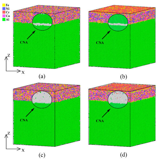
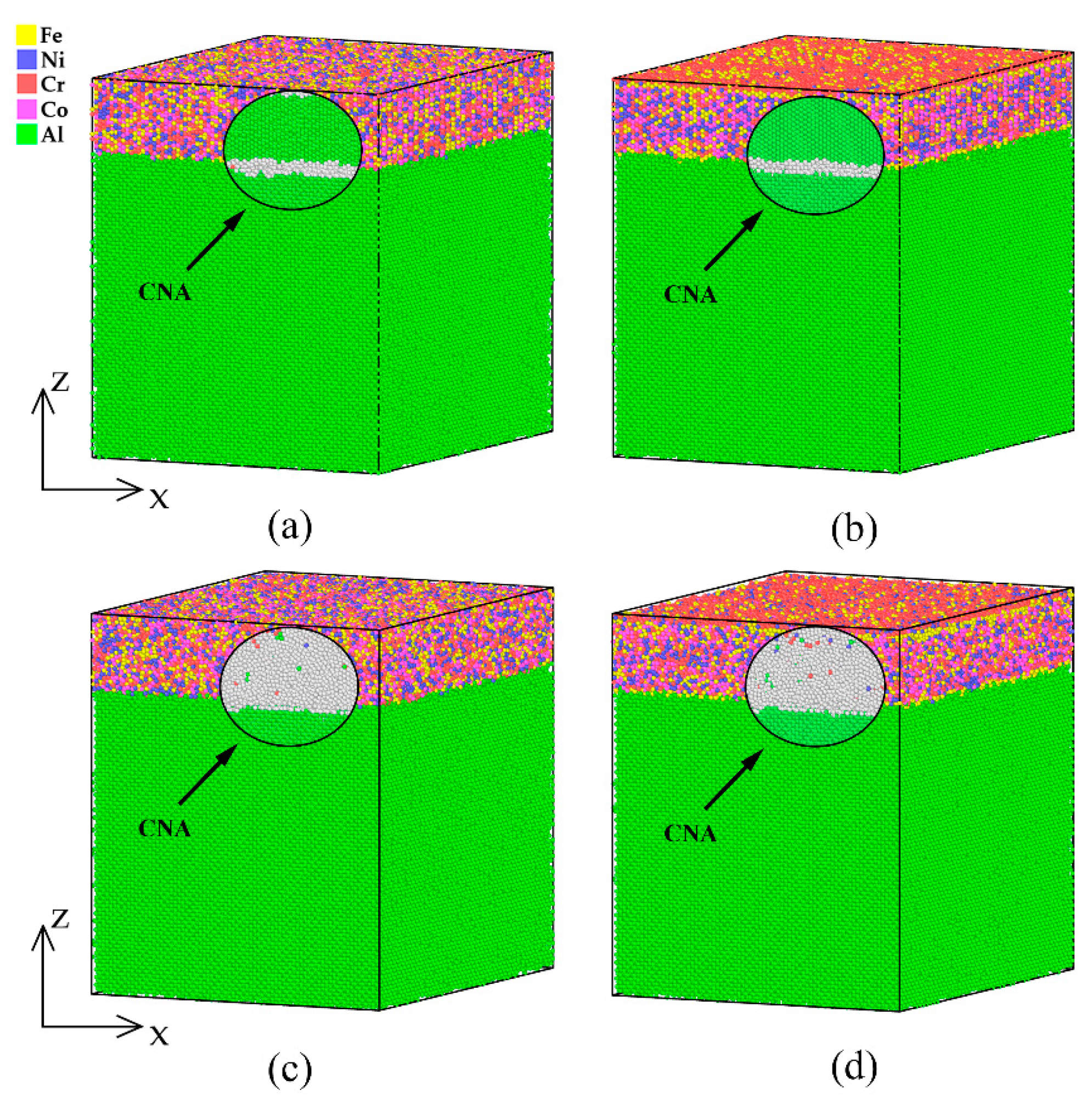
MC/MD relaxation reduces the potential energy of the FeNiCrCo layer and modifies its local chemical environment while preserving the overall structural state of each coating. The crystalline coating retains its FCC lattice after relaxation (Figure 3a,b), whereas the quenched coating remains predominantly assigned to non-crystalline local environments by a-CNA (Figure 3c,d). The observed near-surface compositional redistribution is therefore interpreted as chemical short-range ordering induced by the MC/MD procedure.
Figure 3.
Atomic structures before (a,c) and after (b,d) MC/MD relaxation for FeNiCrCo/Al samples with crystalline (a,b) and amorphous (c,d) upper layers. Adaptive common-neighbor analysis (a-CNA): green denotes atoms assigned to FCC local environments, whereas gray denotes atoms not assigned to the FCC, HCP, or BCC templates. In the chemically disordered coating, gray regions are interpreted as non-crystalline local environments rather than as a unique phase identifier.
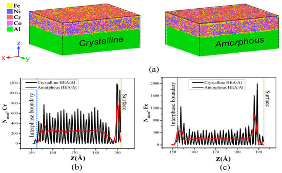
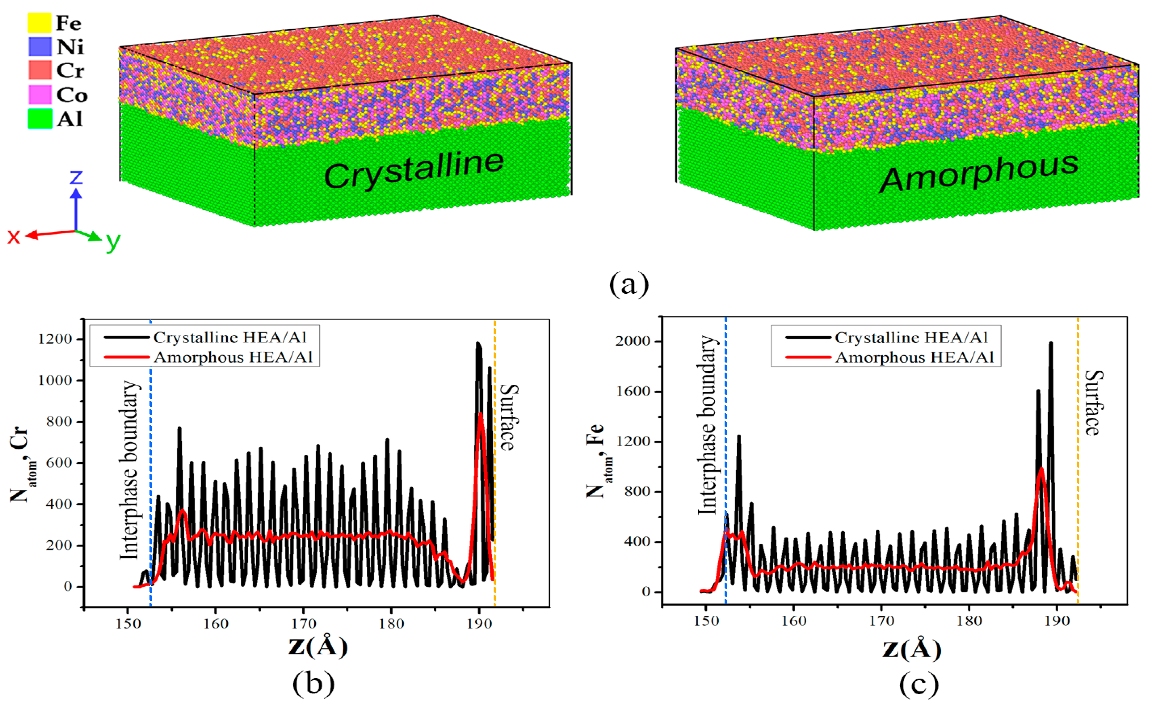
Additional information on the relaxation is provided by the concentration profiles across the coating thickness (Figure 4). After the MC/MD treatment, the surface layer becomes enriched in Cr and Fe atoms [29,32,41]. In the crystalline coating, the concentration profiles along the z-axis exhibit sharper and more oscillatory variations, which are associated with the ordered arrangement of atomic planes, whereas in the amorphous layer the element distribution through the thickness is smoother.
Figure 4.
Atomic configurations and concentration profiles of Cr and Fe in crystalline and amorphous FeNiCrCoAl composites after MC/MD relaxation: (a) atomic distributions in the crystalline and amorphous HEA/Al systems; (b) Cr concentration profile; (c) Fe concentration profile along the Z-direction. Blue and orange dashed lines mark the HEA/Al interface and the free surface, respectively.
Figure 4 also indicates that Cr enrichment is more pronounced near the free surface than near the FeNiCrCo/Al interface.
3.2. Indentation
The indentation results demonstrate how the structural state of the FeNiCrCo coating and temperature jointly control the mechanical response of the FeNiCrCo/Al system, the level of resistance to penetration, and the way in which material is redistributed in the contact zone [23,25,39]. The most informative cases are comparisons between amorphous and crystalline coatings at two indentation depths and two temperatures, because differences in the atomic organization of the layer are directly reflected in both the shape of the force–depth curves F(d) and the geometry of the imprint and plastic zone under the indenter. Unless stated otherwise, all reported values (e.g., peak forces) are expressed as mean ± standard deviation, calculated from three independent simulation runs for each specific condition.
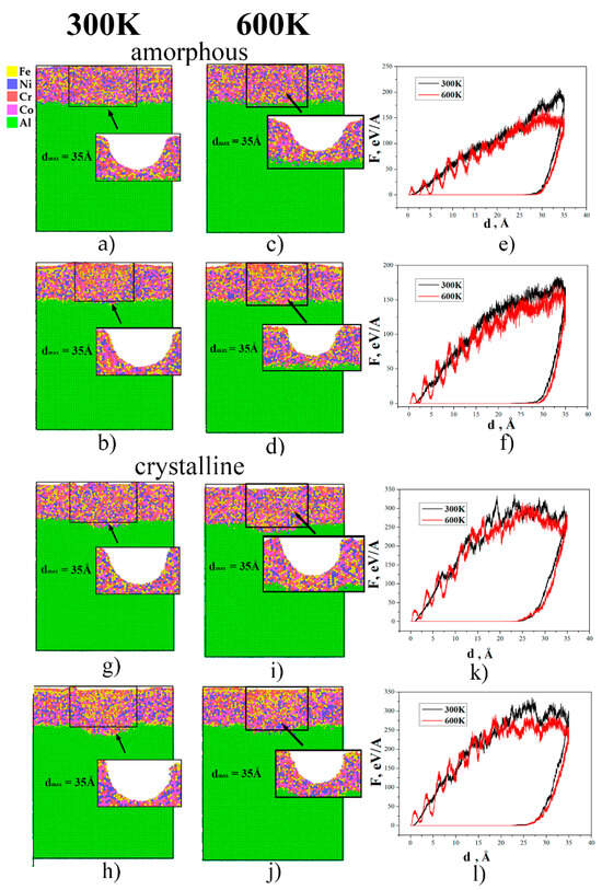
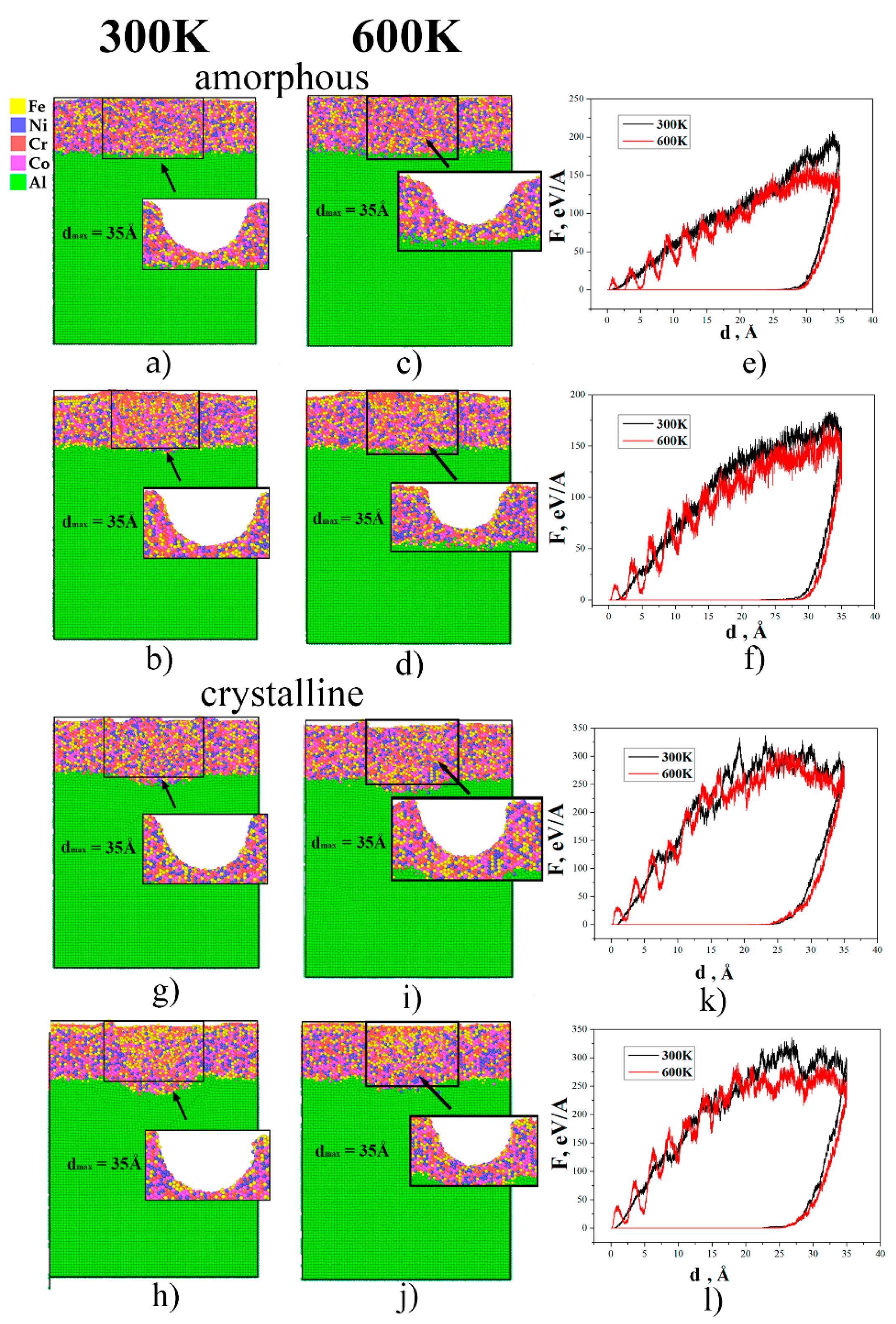
At the shallower indentation depth dmax = 35 Å, deformation is mainly confined to the FeNiCrCo layer, and the contrast between the amorphous and crystalline coatings is particularly pronounced (Figure 5). For the amorphous coating, the configurations in Figure 5a–d show the formation of a comparatively smooth imprint, while the structurally disturbed region is largely limited to the coating thickness; at 300 K (Figure 5a,b) the deformation is localized in the upper part of the FeNiCrCo layer, and the FeNiCrCo/Al interface remains almost undistorted. The corresponding force–depth curves F(d) in Figure 5e,f obtained for 300 and 600 K and different relaxation schemes exhibit relatively low maximum forces of about 220 ± 9 eV/Å and 180–190 ± 8 eV/Å and have a smooth profile without abrupt drops. This comparatively smooth response is consistent with distributed local atomic rearrangements in the amorphous layer. Increasing the temperature to 600 K (Figure 5c–f) broadens the zone of local rearrangements and enhances the involvement of the near-surface region and the interface, but the mechanical response of the amorphous coating remains smooth, and the peak forces decrease to approximately 180–190 ± 8 eV/Å.
Figure 5.
Indentation (dmax = 35 Å) of the FeNiCrCo/Al system with amorphous (top row, panels (a–f)) and crystalline (bottom row, panels (g–l)) surface layers at 300 and 600 K. Panels (a–d) and (g–j) show representative atomic configurations for the amorphous and crystalline coatings at 300 and 600 K, respectively. Panels (e,f,k,l) show the corresponding force–depth trajectories.
At the same nominal indentation depth, the crystalline coating exhibits a markedly different response. The configurations in Figure 5g–j reveal a more sharply defined imprint and a compactly localized distorted region beneath the indenter and in the vicinity of the FeNiCrCo/Al interface. Already at 300 K (Figure 5g,h), the maximum indentation stage and the subsequent unloading are accompanied by the formation of regions containing HCP-like and non-FCC local environments, consistent with defect-related lattice rearrangement in the Al substrate. The black F(d) curves in Figure 5k,l, corresponding to 300 K, reach higher maximum forces of about 330–340 ± 11 eV/Å and display a pronounced step-like shape, which indicates a sequence of discrete structural rearrangements in the crystalline lattice. Upon increasing the temperature to 600 K (Figure 5i–l), the spatial extent of regions assigned to non-FCC local environments expands, and the maximum forces are slightly reduced to 320–330 ± 13 eV/Å, while the step-like character of the F(d) curves is preserved. Within the present high-rate MD protocol, this indicates that the crystalline coating retains a comparatively localized and intermittent deformation response at 600 K. The curves (Figure 5 and Figure 6) are used for comparative analysis of indentation resistance and deformation intermittency under the common simulation protocol; they are not used for a conventional Oliver–Pharr evaluation because the present deeply embedded spherical-indenter geometry does not satisfy the required continuum contact assumptions.
Figure 6.
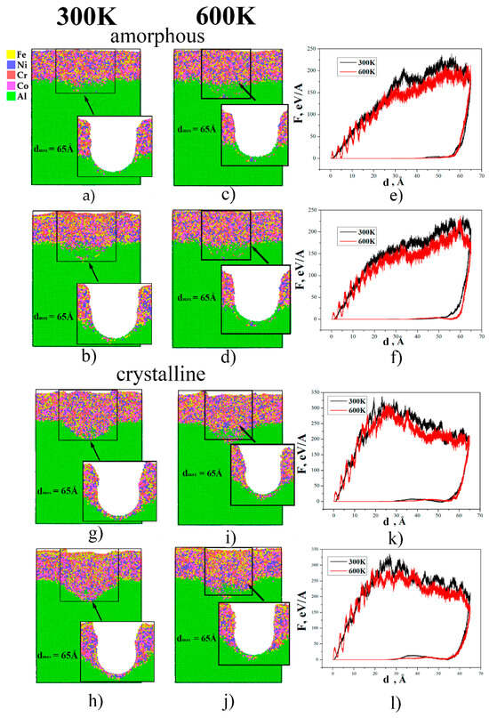
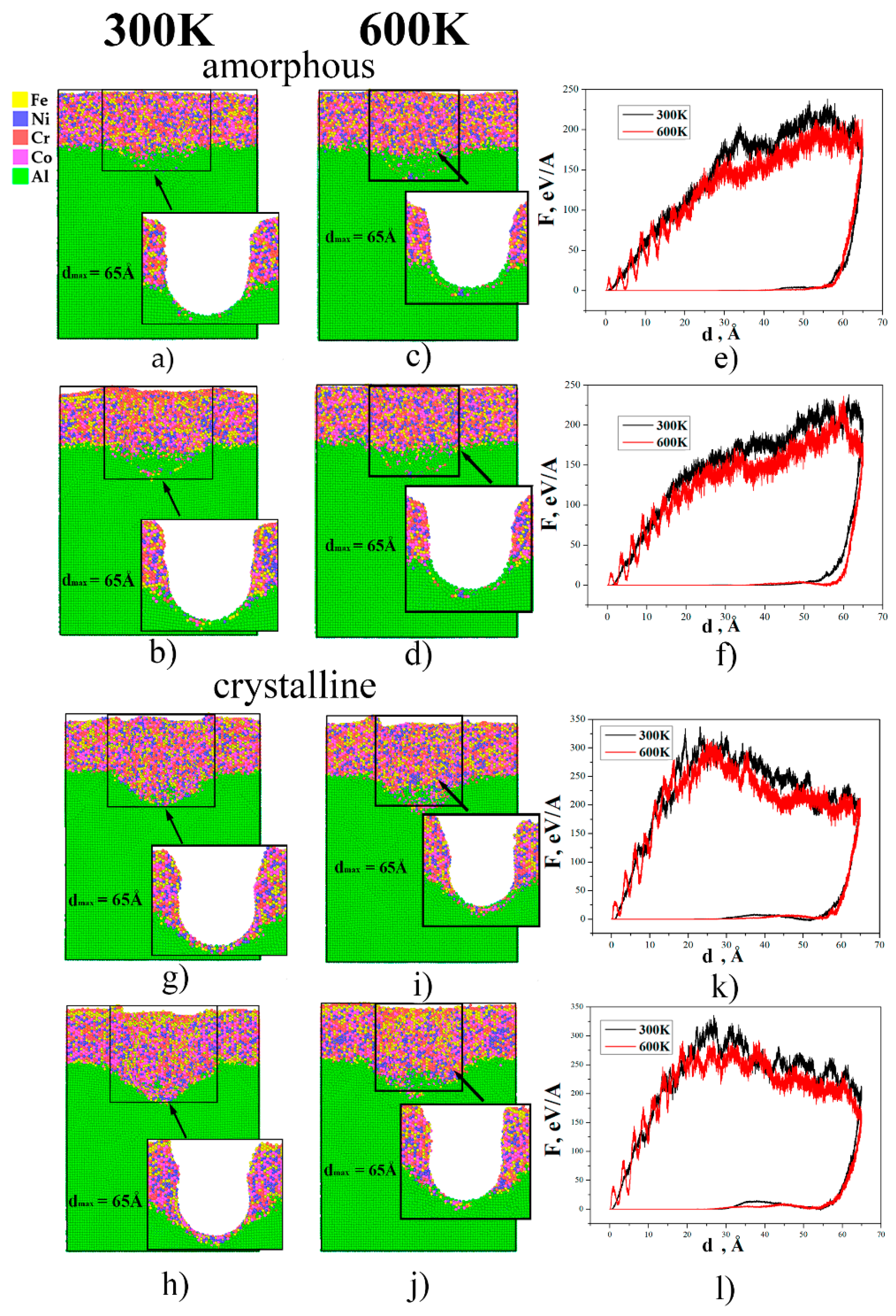
Indentation (dmax = 65 Å) of the FeNiCrCo/Al system with amorphous (top row, panels (a–f)) and crystalline (bottom row, panels (g–l)) surface layers at 300 and 600 K. Panels (a–d) and (g–j) show representative atomic configurations for the amorphous and crystalline coatings at 300 and 600 K, respectively. Panels (e,f,k,l) show the corresponding force–depth trajectories.
When the maximum indentation depth is increased to dmax = 65 Å, the Al substrate becomes strongly involved in the deformation process (Figure 6). For the amorphous coating, the configurations in Figure 6a–d show that the imprint penetrates through the entire FeNiCrCo layer and reaches the substrate: at 300 K (Figure 6a,b) the structurally disturbed region beneath the indenter becomes deeper, and the FeNiCrCo/Al interface is markedly bent. The black F(d) curves in Figure 6e,f, corresponding to 300 K, exhibit maximum forces of about 220–230 ± 9 eV/Å and 225–235 ± 8 eV/Å and maintain a smooth profile without sharp force drops. This indicates that the amorphous layer no longer completely shields the substrate, yet the lack of long-range order still promotes a relatively uniform redistribution of deformation. At 600 K (Figure 6c–f), the zone of structural rearrangements in the amorphous coating and in the upper part of the Al substrate expands further, and the red F(d) curves display somewhat lower maxima, around 210–220 ± 7 eV/Å and 220–230 ± 8 eV/Å, together with more pronounced local oscillations compared with 300 K. Nevertheless, in both temperature regimes the mechanical response of the amorphous coating remains smoothed, and plastic deformation in the substrate is distributed rather than strongly localized.
For the crystalline coating at dmax = 65 Å, the highest force levels among all considered regimes are obtained in Figure 6g–l. At 300 K, the plastic zone remains concentrated beneath the indenter and around the interface, although structural changes extend into the Al substrate. The black F(d) curves in Figure 6k,l reach 330–340 ± 15 eV/Å and retain a step-like shape over the entire depth range, indicating that the stiff crystalline layer transfers the load into the substrate through localized regions of high stress and discrete lattice rearrangements. When the temperature is raised to 600 K (Figure 6i–l), the structurally transformed region under the indent grows and penetrates deeper into the Al substrate, while the red curves show reduced maximum forces of about 300–310 ± 12 eV/Å and 280–290 ± 10 eV/Å. The step-like character of F(d) is still preserved, which means that the temperature increase facilitates the development of plastic deformation in the substrate but does not alter the localized and discrete nature of the mechanical response of the crystalline coating [36,38,40].
The force–depth trajectories are interpreted comparatively rather than through a conventional Oliver–Pharr procedure. In particular, the 65 Å case corresponds to a deeply embedded virtual spherical indenter in a nanoscale layered system, where the contact area evolves across the coating–substrate interface and where continuum assumptions underlying the extraction of hardness and reduced modulus from unloading stiffness are not satisfied quantitatively. The present force values therefore serve as relative indicators of indentation resistance for systems simulated with the same indenter geometry, loading velocity, and boundary conditions.
4. Discussion
4.1. Structural Evolution Under Indentation
The structural evolution of the FeNiCrCo/Al system under indentation is governed by a combination of the phase state of the coating, the indentation depth, the temperature, and the preceding MC/MD relaxation. Increasing the temperature from 300 to 600 K enlarges the scale of plastic restructuring in all cases; however, the way in which this enhancement manifests itself differs markedly for the amorphous and crystalline coatings.
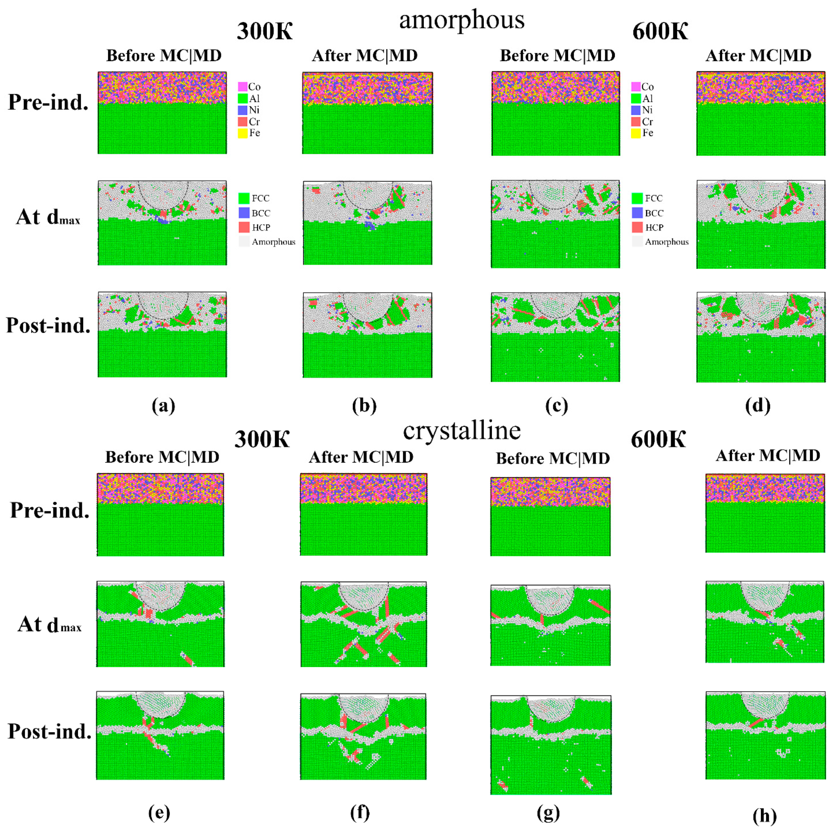
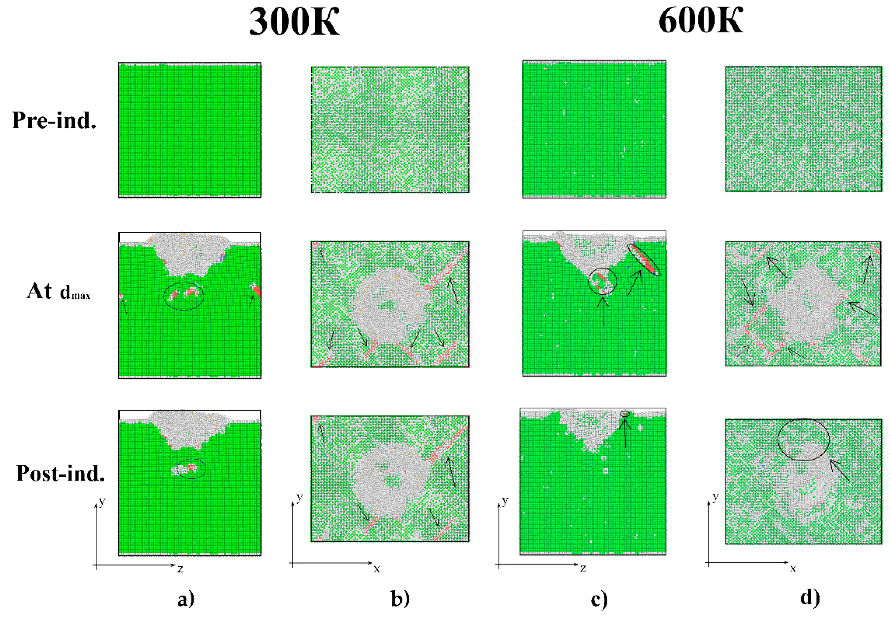
At an indentation depth of dmax = 35 Å, the features of the system response are clearly seen in Figure 7. For the amorphous coating (Figure 7a–d), the material remains structurally disordered before loading at both temperatures. The relaxed and non-relaxed configurations differ primarily in their local chemical and atomic arrangements established during the MC/MD procedure. Because a separate quantitative residual-stress analysis was not performed, the influence of relaxation is discussed here in terms of the resulting structural configurations and the subsequent comparative indentation response. At the stage of maximum indentation depth, a locally densified and structurally perturbed region forms beneath the indenter; however, these zones do not develop into extended defect bands. After unloading (bottom row of the amorphous block in Figure 7a–d), the system largely returns to its initial disordered state, and the residual changes are concentrated mainly in the imprint region and near the FeNiCrCo/Al interface. Increasing the temperature to 600 K broadens the zone of local rearrangements and makes the residual imprint more pronounced, but the deformation pattern remains predominantly distributed [52,53,54,61].
Figure 7.
Atomic structure of the samples with amorphous and crystalline FeNiCrCo surface layers at 300 and 600 K before indentation (top row), at the maximum indentation depth of 35 Å (middle row), and after unloading (bottom row): (a,c,e,g) model without prior MC/MD relaxation; (b,d,f,h) model after relaxation. The dashed line indicates the position of the high-entropy alloy–indenter boundary.
In the crystalline case at the same indentation depth dmax = 35 Å, the structural evolution is qualitatively different (Figure 7e–h). Already at 300 K, the configurations at maximum indentation and after unloading show the formation of HCP-identified local environments and defect bands in the Al substrate beneath the imprint. In the FCC Al substrate, these HCP-like regions are consistent with stacking-fault-related configurations generated by partial-dislocation activity. In contrast to the amorphous coating, the deformation here has a more discrete character and is accompanied by the development of a stable residual defect structure. At 600 K, the regions assigned by a-CNA to HCP-like and non-FCC local environments become spatially more extended in the representative configurations. In the FCC Al substrate, HCP-like environments are consistent with stacking-fault-related local configurations; however, at elevated temperature, the classification is influenced by both genuine defect structures and thermal/lattice distortion. Therefore, the observed spatial patterns are interpreted comparatively together with the force–depth response and the persistence of features after unloading.
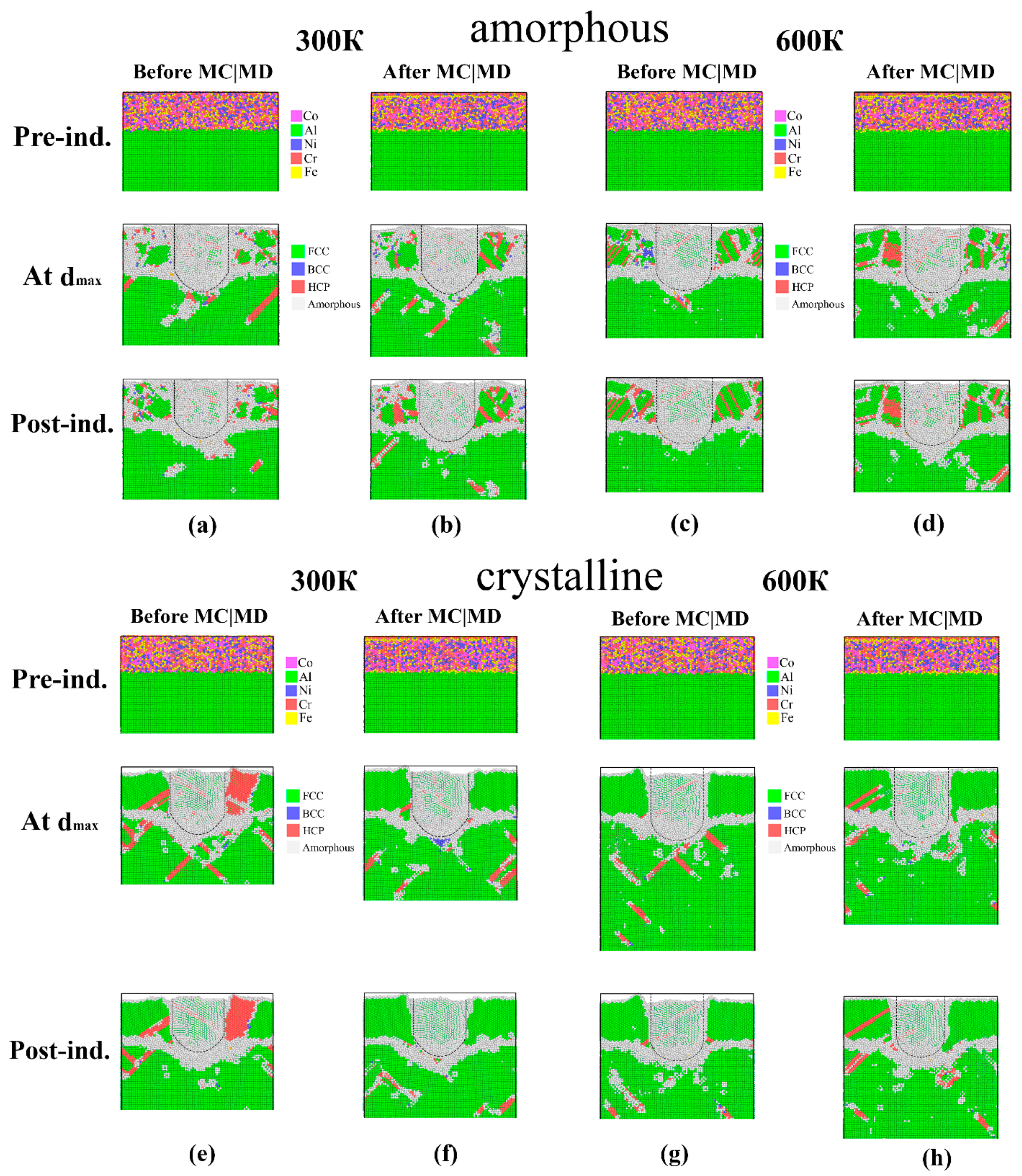
When the indentation depth is increased to dmax = 65 Å, the scale of structural changes grows substantially, as illustrated in Figure 8. For the amorphous coating (Figure 8a–d), a deeper plastic zone is formed during loading, and the FeNiCrCo/Al interface experiences pronounced bending and rearrangement. Nevertheless, even at this depth, the amorphous layer does not give rise to long, well-defined defect bands; the structural response is still governed mainly by distributed atomic flow and local rearrangements in the vicinity of the contact. A comparison of the configurations at 300 and 600 K (Figure 8a–d) shows that at the higher temperature the region of disturbed structure beneath the indenter becomes wider and deeper, and the residual distortions after unloading are more pronounced, particularly near the interface.
Figure 8.
Atomic structure of the samples with amorphous and crystalline FeNiCrCo surface layers at 300 and 600 K before indentation (top row), at the maximum indentation depth of 65 Å (middle row), and after unloading (bottom row): (a,c,e,g) model without prior MC/MD relaxation; (b,d,f,h) model after relaxation. The dashed line indicates the position of the high-entropy alloy–indenter boundary.
For the crystalline coating at dmax = 65 Å (Figure 8e–h), the most intensive structural evolution is observed. Already at 300 K, the configurations at maximum indentation and after unloading reveal well-developed HCP regions and extended defect bands in the Al substrate, propagating from the contact zone into the bulk. At 600 K, these features become even more pronounced: the defect zones occupy a larger volume, penetrate deeper into the substrate, and the residual defect structure after unloading appears more ramified. Comparison of the non-relaxed and relaxed configurations demonstrates that preliminary MC/MD relaxation does not suppress intensive plastic rearrangement but reduces its fragmentation and makes the main bands of lattice disturbance more coherent, while decreasing the number of secondary small defect clusters.
Taken together, the data in Figure 7 and Figure 8 indicate that raising the temperature from 300 to 600 K enhances structural evolution in both amorphous and crystalline coatings, but in different ways. In the amorphous layer, the temperature increase primarily enlarges the scale of local rearrangements and the size of the residual imprint, while the deformation remains largely distributed. In the crystalline coating, the same temperature change promotes the development of more extended HCP regions and oriented defect bands in the Al substrate, pointing to a stiffer and more localized load-transfer mechanism. In both cases, the relaxed configurations display a more reproducible defect morphology than the initially non-relaxed systems, particularly at 600 K and dmax = 65 Å. This observation suggests that MC/MD relaxation reduces the influence of initial non-equilibrium atomic configurations on the subsequent deformation response.
4.2. Features of Deformation of Aluminum Substrate
The aluminum substrate plays a decisive role in setting the scale and character of the plastic zone under indentation, showing high sensitivity both to temperature conditions and to the type of FeNiCrCo surface coating. In the case of bare aluminum without a coating, a deep deformation zone develops beneath the indenter already at 300 K, characterized by a high density of HCP regions and extended disturbance bands that propagate far beyond the contact area (Figure 9a,b). After unloading, a pronounced residual imprint with a substantially increased defect density is preserved, which indicates significant accumulation of dislocation structures and limited elastic recovery.
Figure 9.
Evolution of structural changes in the aluminum substrate during indentation of pure Al: (a) projection along the YZ plane and (b) along the YX plane at 300 K; (c) projection along the YZ plane and (d) along the YX plane at 600 K.
When the temperature is increased to 600 K, the deformation effects in pure Al are markedly intensified: the plastic zone becomes significantly wider and penetrates deeper into the material, and the intensity of defect formation rises (Figure 9c,d). A more pronounced involvement of the bulk substrate layers is observed, with the formation of branched networks of defect bands and a reduced degree of relaxation after unloading. This temperature-driven enhancement highlights the role of thermal activation in facilitating dislocation motion and promoting irreversible structural changes in the Al substrate.
Applying an amorphous FeNiCrCo coating substantially mitigates this intense substrate response by promoting a more uniform load distribution through local atomic rearrangements in the surface layer. This limits the penetration depth of the plastic zone into aluminum and prevents the formation of long, oriented defects. In contrast, the crystalline coating increases the overall load-bearing capacity of the system, but under deep indentation it transfers localized stress peaks into the substrate, triggering the development of HCP regions and discrete defect bands similar to those observed in pure aluminum [62,63,64].
The transition from 300 to 600 K in all configurations enhances the involvement of the aluminum substrate in the deformation process; however, the nature of this enhancement strongly depends on the phase state of the coating. The amorphous layer promotes further delocalization of stresses and preserves the distributed character of plasticity even at elevated temperatures. Within the present nanoindentation simulations, the crystalline coating provides greater local resistance to penetration but is associated with more localized substrate deformation at elevated temperature. Thus, by choosing the structural state of FeNiCrCo, one can deliberately tune the balance between load-bearing capacity and control over substrate deformation.
4.3. Spatial Redistribution of Local Kinetic Energy at the HEA–Al Interface
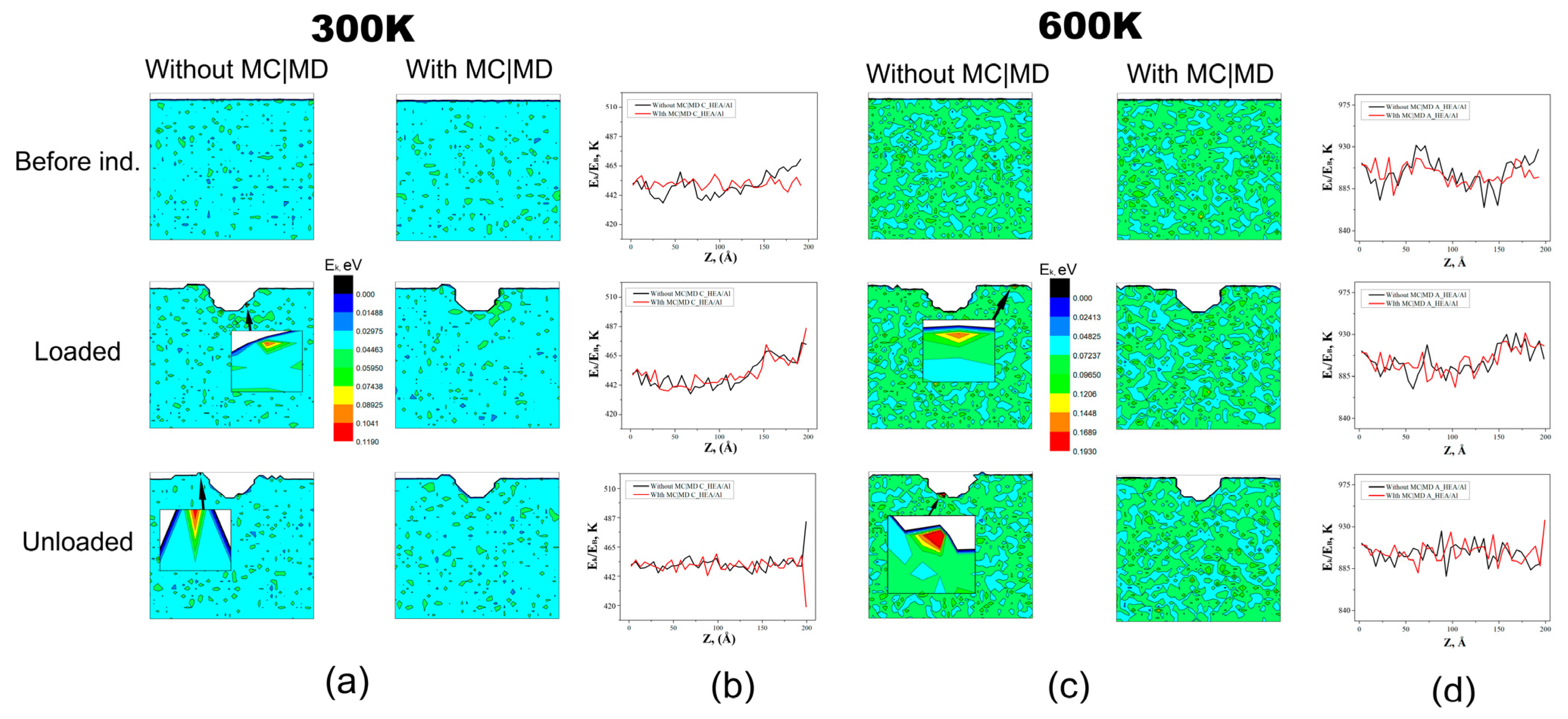
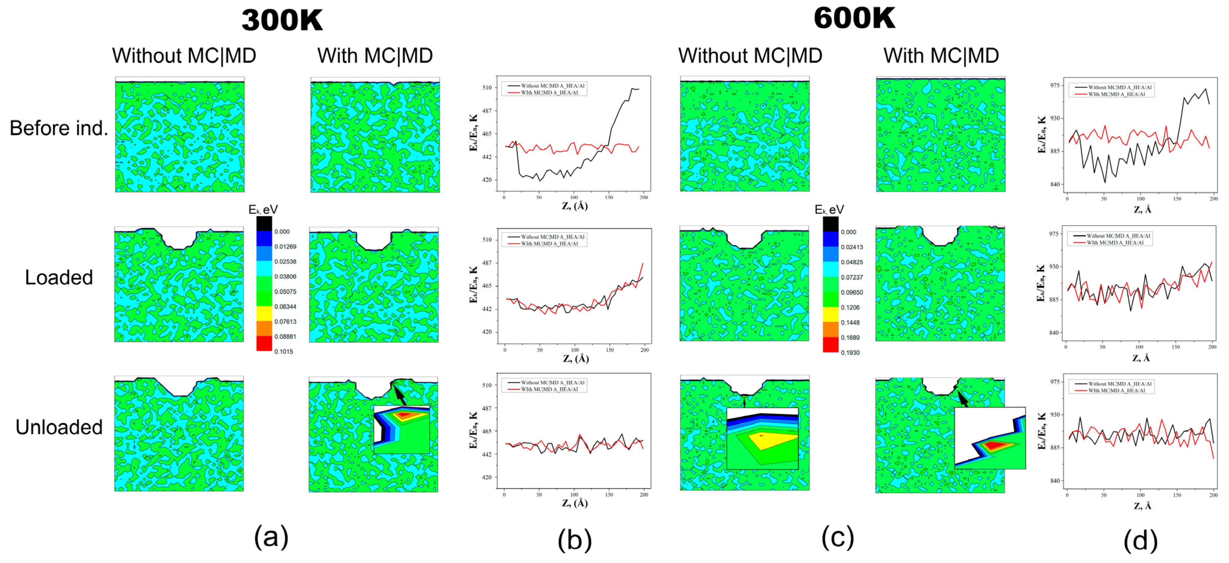
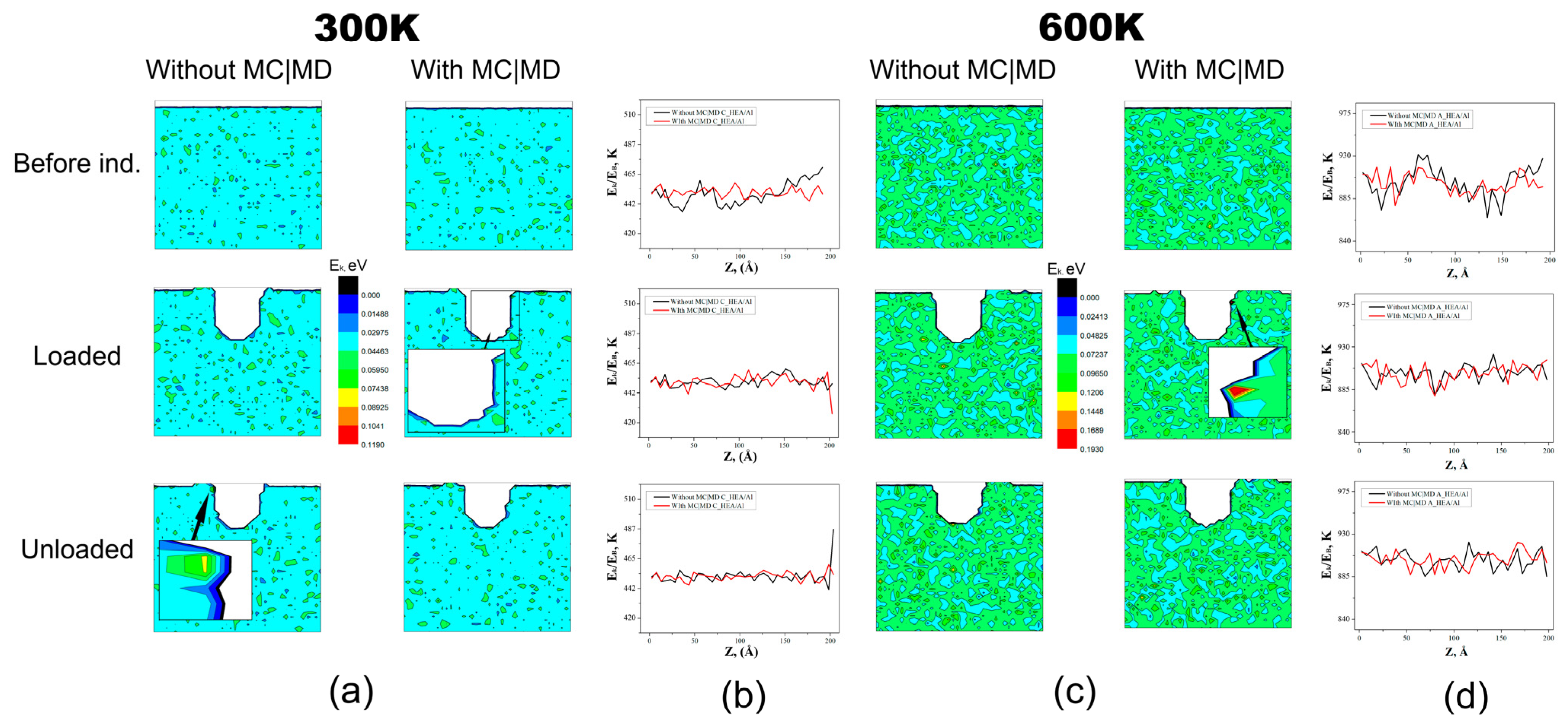
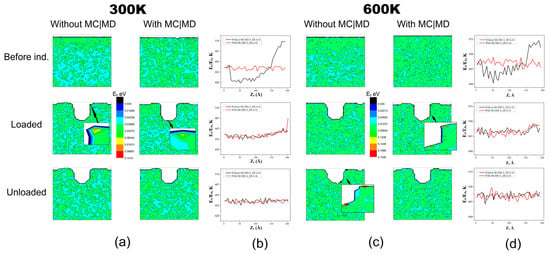
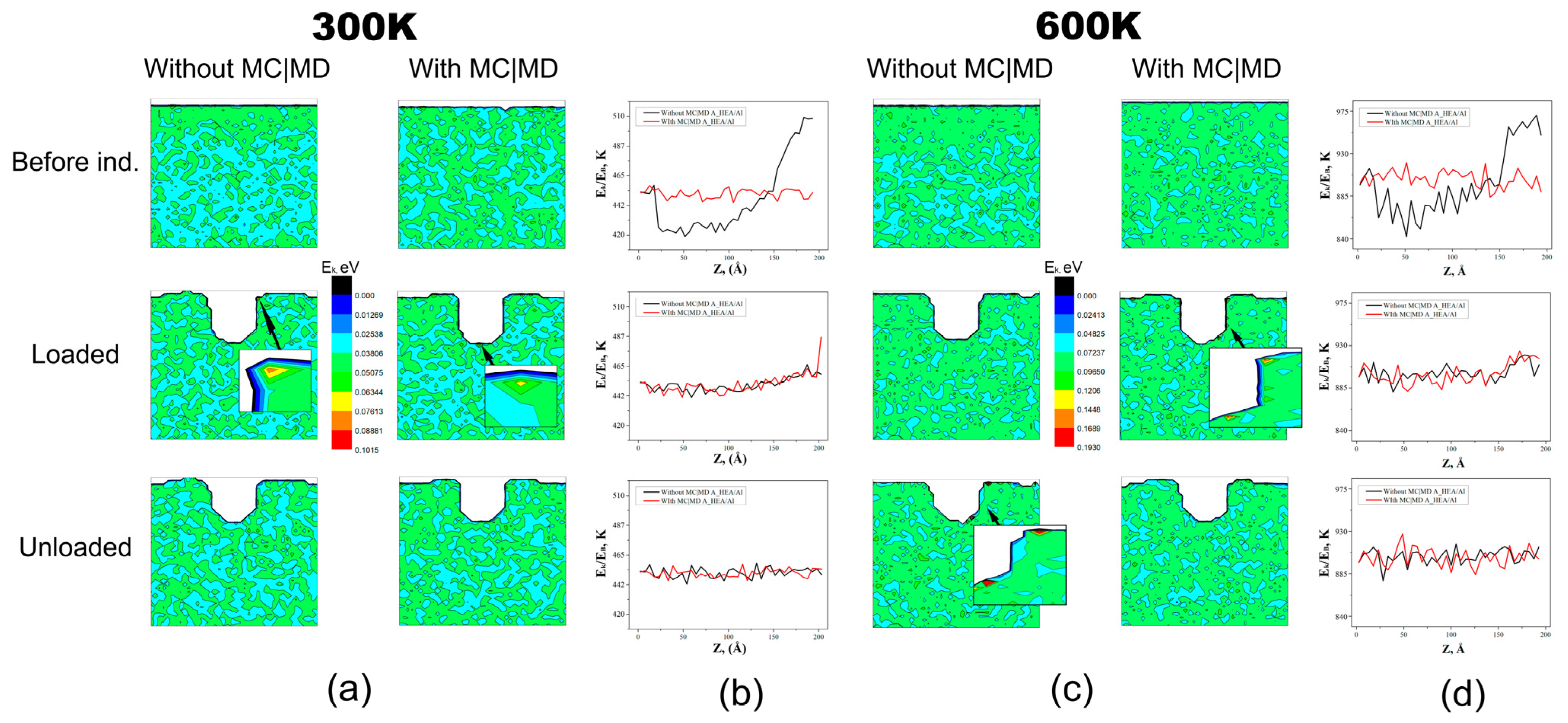
The spatially binned local kinetic-energy maps and corresponding surface-normal kinetic-energy profiles in Figure 10, Figure 11, Figure 12 and Figure 13 provide a qualitative visualization of the spatial distribution of per-atom kinetic energy under the same indentation and post-processing protocol. Because the fields were calculated from instantaneous snapshots without subtraction of local center-of-mass velocity and without time averaging, they do not represent a complete thermodynamic decomposition of indenter work, local equilibrium temperature, irreversible heat, or defect-storage energy. They are used only to compare the relative spatial localization of the kinetic-energy signal among systems.
Figure 10.
Spatially binned local kinetic-energy maps Ek (a,c) and corresponding surface-normal kinetic-energy profiles (b,d) for the crystalline FeNiCrCo/Al composite indented to dmax = 35 Å. Results without and with MC/MD relaxation are compared before indentation, at maximum loading, and after unloading. Kinetic-energy-derived profile expressed in temperature units; no local streaming-velocity correction was applied.
Figure 11.
Spatially binned local kinetic-energy maps Ek (a,c) and corresponding surface-normal kinetic-energy profiles (b,d) for the amorphous FeNiCrCo/Al composite indented to dmax = 35 Å. Results without and with MC/MD relaxation are compared before indentation, at maximum loading, and after unloading. Kinetic-energy-derived profile expressed in temperature units; no local streaming-velocity correction was applied.
Figure 12.
Spatially binned local kinetic-energy maps Ek (a,c) and corresponding surface-normal kinetic-energy profiles (b,d) for the crystalline FeNiCrCo/Al composite indented to dmax = 65 Å. Results without and with MC/MD relaxation are compared before indentation, at maximum loading, and after unloading. Kinetic-energy-derived profile expressed in temperature units; no local streaming-velocity correction was applied.
Figure 13.
Spatially binned local kinetic-energy maps Ek (a,c) and corresponding surface-normal kinetic-energy profiles (b,d) for the amorphous FeNiCrCo/Al composite indented to dmax = 65 Å. Results without and with MC/MD relaxation are compared before indentation, at maximum loading, and after unloading. Kinetic-energy-derived profile expressed in temperature units; no local streaming-velocity correction was applied.
At dmax = 35 Å, the indenter remains mainly within the FeNiCrCo coating. In the crystalline composite Figure 10, the region of elevated Ek beneath the indenter is comparatively compact and wedge-shaped, consistent with localized deformation and the defect structures observed in the corresponding atomistic configurations. More generally, nonlinear discrete lattices can support strongly localized dynamical excitations and energy-transport modes, highlighting the ability of atomistic systems to concentrate mechanical energy within restricted spatial regions [65].
In contrast, the amorphous composite in Figure 11 exhibits a broader and more diffuse distribution of kinetic energy, consistent with deformation through distributed atomic rearrangements and shear-transformation-like events. Within the common binning and visualization procedure, the crystalline system exhibits a more compact region of elevated local kinetic energy, whereas the amorphous system exhibits a spatially broader kinetic-energy distribution.
The comparison of Figure 10 and Figure 11 demonstrates the effect of increasing temperature from 300 to 600 K. At 600 K, the baseline kinetic-energy level is higher because the thermostat target is higher, and the spatial extent of the elevated kinetic-energy signal becomes broader in the representative snapshots. Nevertheless, the fundamental structural contrast is preserved: the crystalline coating retains a localized kinetic-energy perturbation, while the amorphous coating accommodates the imposed work through a more homogeneous and diffuse response. MC/MD relaxation reduces background fluctuations in the Ek maps and TZ profiles, thereby making these structural differences more distinct.
At dmax = 65 Å, the indenter penetrates through the coating and directly involves the FeNiCrCo/Al interface and Al substrate in deformation, as illustrated in Figure 12 and Figure 13. At dmax = 65 Å, the region with elevated local kinetic energy extends into the interface and substrate. This spatial pattern is consistent with the greater involvement of the coating–substrate system in deformation at deep indentation; however, the kinetic-energy maps alone do not resolve the separate contributions of elastic storage, defect formation, collective motion, and irreversible heating. In nonlinear lattice systems, localized vibrational modes such as discrete breathers can contribute to energy storage, transport, and the effective macroscopic response, demonstrating the broader relevance of localized energy redistribution during strongly nonequilibrium deformation processes [66].
In the crystalline composite (Figure 12), the elevated local kinetic-energy signal remains comparatively compact beneath the indenter and near the interface. In the amorphous composite (Figure 13), the corresponding signal extends over a wider volume of the coating–substrate system.
At 600 K, the elevated-Ek region extends farther toward the interface and substrate in both systems. In the crystalline composite, the region remains comparatively concentrated beneath the indenter, whereas the amorphous composite exhibits a broader spatial distribution. These observations are consistent with the structural patterns identified in Figure 7 and Figure 8.
4.4. Chemical Redistribution During MC/MD Relaxation
The MC/MD relaxation procedure modifies the chemical distribution and potential-energy state of the FeNiCrCo coating before indentation. As shown in Figure 4, the relaxed systems exhibit Fe and Cr enrichment near the free surface, whereas the chemical distribution close to the FeNiCrCo/Al interface is less strongly altered. These observations indicate that the MC/MD protocol produces a lower-energy chemically redistributed initial state within the selected empirical potential. The present data do not establish a unique causal relation between this chemical redistribution and the subsequent spatial kinetic-energy fields during indentation; therefore, the latter comparison is interpreted primarily in terms of the different amorphous and crystalline structural states.
During MC/MD relaxation, compositional rearrangement and potential-energy reduction occur concurrently. Atomic swaps modify the local chemical environments, while the associated structural relaxation lowers the mean potential energy of the selected region. Mass transfer is manifested by the redistribution of Fe and Cr within the selected HEA region, whereas energy relaxation is reflected by changes in the mean potential energy of atoms. In both cases, the driving force is the tendency of the system to reduce local non-equilibrium: chemical non-equilibrium is reduced through the formation of preferred compositional environments, whereas energetic non-equilibrium is reduced through the elimination of unfavorable atomic configurations.
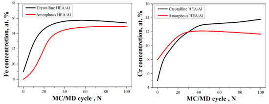
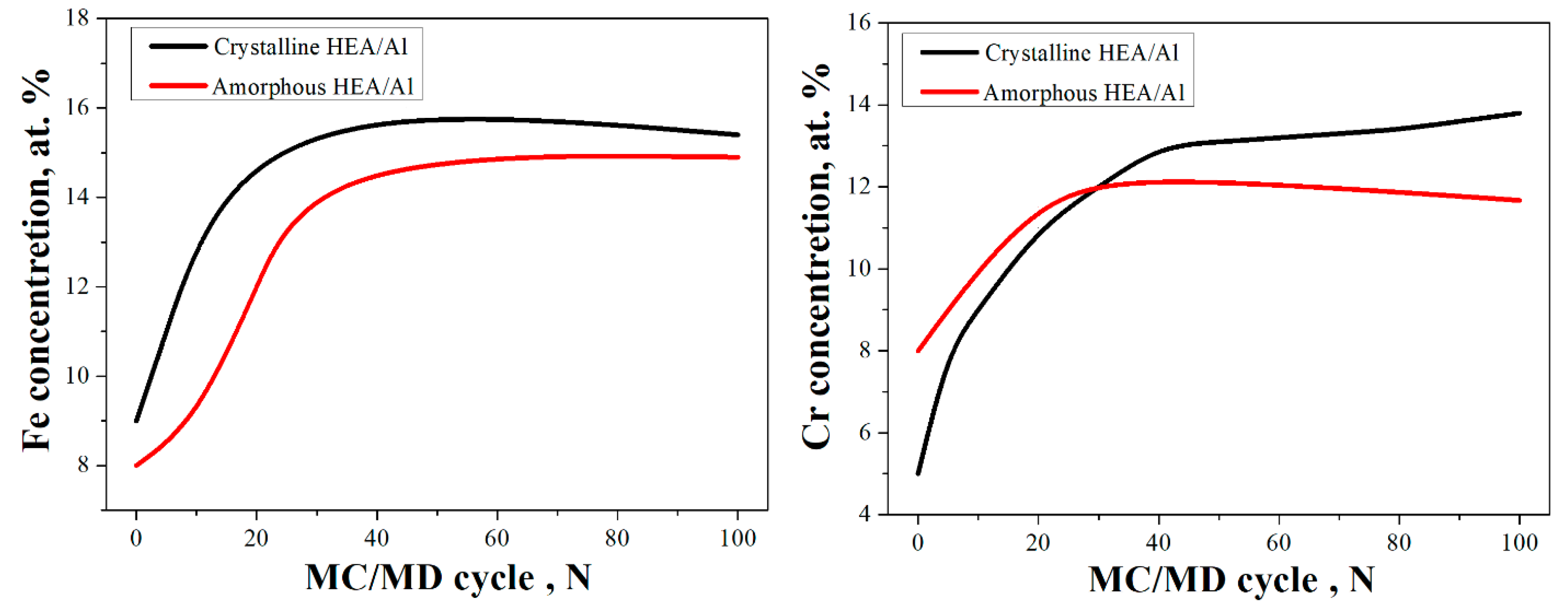
The evolution of Fe and Cr concentrations shown in Figure 14 indicates that atomic exchanges do not result in simple random mixing of the components. Instead, a locally preferred elemental distribution develops in both systems. The Fe and Cr concentrations in the selected spatial region evolve differently in the crystalline and amorphous coatings. Because the atom count within this fixed region changes during relaxation, these trends should be interpreted together with the occupancy variation in the region. In the amorphous layer, structural disorder expands the range of possible local atomic environments; consequently, chemical rearrangement follows a different pathway and leads to different quasi-stationary concentrations.
Figure 14.
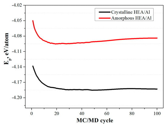
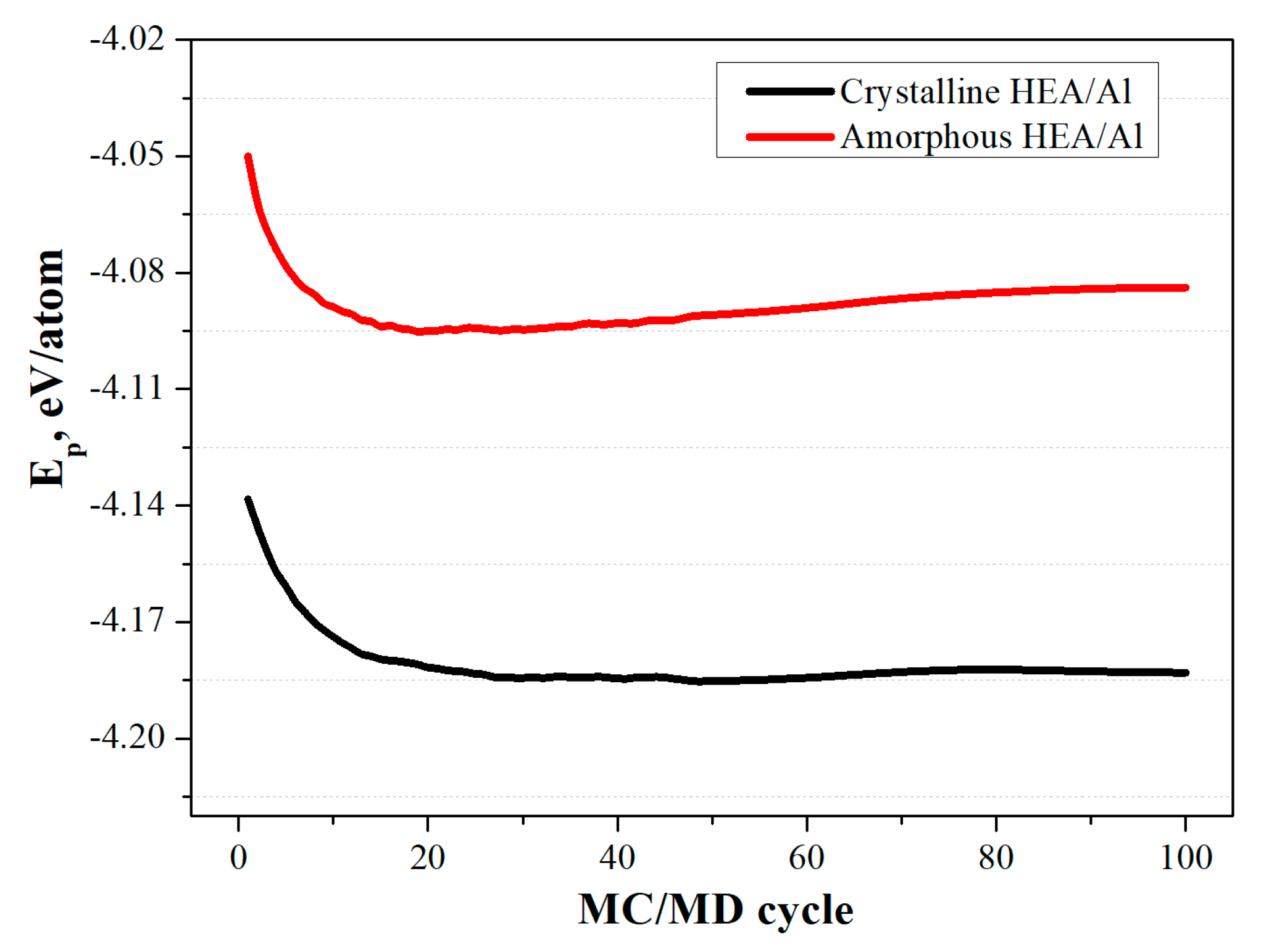
Evolution of Fe and Cr concentrations in the selected HEA layer during 100 MC/MD relaxation cycles for crystalline and amorphous HEA/Al systems.
The energetic aspect of this rearrangement is reflected in Figure 15. The rapid decrease in mean potential energy at the beginning of MC/MD relaxation indicates that the initial atomic exchanges are accompanied by the elimination of the most energetically unfavorable local configurations. Thus, compositional redistribution and the reduction in potential energy are interrelated manifestations of a single relaxation process: changes in the chemical environment of atoms enable the system to transition to a more energetically favorable state.
Figure 15.
Evolution of the mean potential energy per atom in the selected HEA layer during 100 MC/MD relaxation cycles for crystalline and amorphous HEA/Al systems.
After the initial relaxation stage, the crystalline system reaches a lower and nearly stationary potential-energy level. This is consistent with the limited set of accessible configurations in an ordered lattice: once locally preferred environments have formed, further atomic exchanges have only a weak effect on the mean energy of the selected region. The amorphous system retains a higher potential-energy level and exhibits more pronounced late-stage rearrangement. The absence of long-range order in the amorphous structure permits the existence of numerous metastable local states; therefore, MC exchanges continue to alter local chemical environments and energetics even after the main relaxation stage has been completed.
It should be noted that the number of atoms in the fixed layer decreased from approximately 23,000 to 20,000 by cycle 48. Therefore, late-stage energy changes, particularly in the amorphous HEA, reflect not only local relaxation but also changes in the instantaneous composition and occupancy of the selected spatial region. Accordingly, the late-stage energy trends should be interpreted with caution, particularly for the amorphous coating. Normalization per atom and use of the same spatial selection criterion improve comparability, but they do not fully eliminate the influence of changes in local occupancy and composition.
Taken together, Figure 4, Figure 14 and Figure 15 show that the MC/MD procedure changes the local chemical distribution and lowers the mean potential energy of the selected FeNiCrCo region. The crystalline and amorphous configurations reach different quasi-stationary structural and energetic states before indentation. These differences provide relevant initial-state context for the subsequent indentation simulations, although the present results do not permit a quantitative separation of the chemical, structural, and kinetic contributions to the indentation response.
4.5. Methodological Limitations
Several limitations should be considered when interpreting the present results. First, the accessible MD time scale requires an indentation velocity substantially higher than experimental nanoindentation rates. The simulations therefore preferentially sample high-rate, nonequilibrium deformation pathways and may not capture slower thermally activated mechanisms, including diffusion-mediated relaxation, recovery, creep, and long-time evolution of shear bands or dislocation structures. Second, the finite simulation cell, periodic boundary conditions, substrate thickness, and boundary/thermal treatment may influence stress-wave propagation, thermal transport, and the spatial extent of the plastic zone. A dedicated size-convergence study, particularly for deep indentation at 600 K, would be required for a quantitative finite-size assessment. Third, local kinetic-energy and local-temperature fields are used as comparative nonequilibrium indicators, not as a direct measurement of heat dissipation or a complete work partitioning. Fourth, the a-CNA labels provide local structural descriptors rather than unique phase or defect identifiers in a chemically disordered multicomponent system. Finally, the results depend on the selected empirical EAM-type potential and should be independently tested using additional validated interatomic models, including machine-learned potentials where appropriate.
5. Conclusions
This molecular dynamics study examined the temperature-dependent nanoindentation response of an idealized FeNiCrCo/Al bilayer system with amorphous and crystalline FeNiCrCo coatings. The work extends the previously reported 300 K baseline for this model system [42] by comparing the structural response and spatial kinetic-energy redistribution at 300 and 600 K.
The main conclusions are as follows:
- At both temperatures, the crystalline FeNiCrCo coating exhibits higher force levels and pronounced force serrations, consistent with intermittent lattice-mediated plasticity and comparatively localized deformation beneath the indenter.
- The amorphous coating shows lower force levels and smoother force–depth trajectories, consistent with distributed local atomic rearrangements and a broader deformation-affected region.
- Increasing temperature from 300 to 600 K enlarges the region affected by indentation and increases the involvement of the coating–substrate interface and Al substrate. However, the contrast between the two structural states remains: the crystalline coating retains a more compact kinetic-energy perturbation, whereas the amorphous coating exhibits a more spatially distributed response.
- MC/MD pre-relaxation reduces the influence of the initially prepared atomic configuration and permits a more consistent comparison of the structure-dependent response. Its effect is interpreted qualitatively, because a separate residual-stress quantification was not performed.
- Adaptive CNA identifies coherent changes in local environments that are consistent with distinct deformation morphologies; nevertheless, these labels are treated as qualitative structural descriptors and not as unique phase or defect identifiers.
The present results should be interpreted as qualitative atomistic trends under the selected EAM potential, finite-cell geometry, boundary conditions, and high-rate indentation protocol. In particular, no direct quantitative extrapolation to experimental hardness, reduced modulus, dissipated heat, or service performance is intended. Future work should include explicit size- and strain-rate-convergence tests, a thermostat/boundary sensitivity analysis, complementary polyhedral template matching (PTM)/ radial distribution functions (RDF)/bond-orientational structural characterization, and validation using independently benchmarked interatomic potentials and experiments.
Author Contributions
Conceptualization, E.A.K.; methodology, E.A.K. and R.I.B.; software, A.A.D. and R.I.B.; investigation, A.A.D. and R.I.B.; writing—original draft preparation, A.A.D., R.I.B., A.M.K., and E.A.K.; writing—review and editing, A.A.D., R.I.B., A.M.K., and E.A.K.; visualization, A.A.D. and A.M.K. All authors have read and agreed to the published version of the manuscript.
Funding
This research was funded by the Russian Scientific Foundation (grant No. 23-11-00364-П).
Data Availability Statement
The data presented in this study are available on request from the corresponding author due to privacy.
Conflicts of Interest
The authors declare no conflicts of interest.
References
- Zhang, Y.; Zuo, T.T.; Tang, Z.; Gao, M.C.; Dahmen, K.A.; Liaw, P.K.; Lu, Z.P. Microstructures and properties of high-entropy alloys. Prog. Mater. Sci. 2014, 61, 1–93. [Google Scholar] [CrossRef] [Scilit]
- Miracle, D.B.; Senkov, O.N. A critical review of high entropy alloys and related concepts. Acta Mater. 2017, 122, 448–511. [Google Scholar] [CrossRef] [Scilit]
- Senkov, O.N.; Wilks, G.B.; Miracle, D.B.; Chuang, C.P.; Liaw, P.K. Refractory high-entropy alloys. Intermetallics 2010, 18, 1758–1765. [Google Scholar] [CrossRef] [Scilit]
- Pickering, E.J.; Jones, N.G. High-entropy alloys: A critical assessment of their founding principles and future prospects. Int. Mater. Rev. 2016, 61, 183–202. [Google Scholar] [CrossRef] [Scilit]
- George, E.P.; Raabe, D.; Ritchie, R.O. High-entropy alloys. Nat. Rev. Mater. 2019, 4, 515–534. [Google Scholar] [CrossRef] [Scilit]
- Gludovatz, B.; Hohenwarter, A.; Catoor, D.; Chang, E.H.; George, E.P.; Ritchie, R.O. A fracture-resistant high-entropy alloy for cryogenic applications. Science 2014, 345, 1153–1158. [Google Scholar] [CrossRef] [Scilit]
- Otto, F.; Dlouhy, A.; Somsen, C.; Bei, H.; Eggeler, G.; George, E.P. The influences of temperature and microstructure on the tensile properties of a CoCrFeMnNi high-entropy alloy. Acta Mater. 2013, 61, 5743–5755. [Google Scholar] [CrossRef] [Scilit]
- Rivera-Diaz-del-Castillo, P.E.J.; Fu, H. Strengthening mechanisms in high-entropy alloys: Perspectives for alloy design. J. Mater. Res. 2018, 33, 2970–2982. [Google Scholar] [CrossRef] [Scilit]
- Gelhinskii, B.; Balyakin, I.; Yuryev, A.; Rempel, A. High-entropy alloys: Properties and prospects of application as protective coatings. Russ. Chem. Rev. 2022, 91, 456–478. [Google Scholar] [CrossRef] [Scilit]
- Cheng, C.; Zhang, X.; Haché, M.J.R.; Zou, Y. Magnetron co-sputtering synthesis and nanoindentation studies of nanocrystalline (TiZrHf)x(NbTa)1−x high-entropy alloy thin films. Nano Res. 2021, 15, 4873–4879. [Google Scholar] [CrossRef] [Scilit]
- Meghwal, A.; Anupam, A.; Murty, B.S.; Berndt, C.C.; Kottada, R.S.; Ang, A.S.M. Thermal Spray High-Entropy Alloy Coatings: A Review. J. Therm. Spray Technol. 2020, 29, 857–893. [Google Scholar] [CrossRef] [Scilit]
- Kim, Y.S.; Park, H.J.; Mun, S.C.; Jumaev, E.; Hong, S.H.; Song, G.; Kim, J.T.; Park, Y.K.; Kim, K.S.; Jeong, S.I.; et al. Investigation of structure and mechanical properties of TiZrHfNiCuCo high entropy alloy thin films synthesized by magnetron sputtering. J. Alloys Compd. 2019, 797, 834–841. [Google Scholar] [CrossRef] [Scilit]
- Srivatsav, V.R.; Ragunath, S.; Radhika, N.; Khan, M.A. Exploring the potential of gas atomized high entropy alloys in thermal spray coatings—A comprehensive review. J. Mater. Chem. A 2024, 12, 29432–29468. [Google Scholar] [CrossRef] [Scilit]
- Aravind Krishna, S.; Noble, N.; Radhika, N.; Saleh, B. A comprehensive review on advances in high entropy alloys: Fabrication and surface modification methods, properties, applications, and future prospects. J. Manuf. Process. 2024, 109, 583–606. [Google Scholar] [CrossRef] [Scilit]
- Sharma, A.; Nandam, S.H.; Hahn, H.; Prasad, K.E. Effect of Structural Relaxation on the Indentation Size Effect and Deformation Behavior of Cu-Zr-Based Nanoglasses. Front. Mater. 2021, 8, 676764. [Google Scholar] [CrossRef] [Scilit]
- NayebPashaee, N.; Bakhtiarifard, F.; Jalali, M.; Khodadostan, A.; Koohfar, A.; Sorkhkolai, S.K.M.; Zamani, S. High-entropy alloy coatings for surface protection and thermal barrier applications: Fundamentals, recent advances, and a critical assessment of their potential as alternatives to conventional coatings. Discov. Mater. 2025, 6, 11. [Google Scholar] [CrossRef] [Scilit]
- Sharma, A. High Entropy Alloy Coatings and Technology. Coatings 2021, 11, 372. [Google Scholar] [CrossRef] [Scilit]
- Sabarinath, S.; Raj, V.; Nair, L.V.; Thomas, V.; Ogunlakin, N.; Saji, V.S. High entropy alloy (HEA) coatings for tribological applications-a review. Results Eng. 2025, 27, 105695. [Google Scholar] [CrossRef] [Scilit]
- Babicheva, R.I.; Semenov, A.S.; Izosimov, A.A.; Korznikova, E.A. Analysis of Short-Range Ordering Effect on Tensile Deformation Behaviour of Equiatomic High-Entropy Alloys TiNbZrV, TiNbZrTa and TiNbZrHf Based on Atomistic Simulations. Modelling 2024, 5, 1853–1864. [Google Scholar] [CrossRef] [Scilit]
- Mishra, D.K.; Bad Jena, S.K.; Pal, S. A Comparative Nanoindentation Study on HEA Coated FCC Metals and Stacking Fault Tetrahedra Evolution in HEA Coated Single Crystal Al: A MD Simulation Study. In Processing and Characterization of Materials; Springer: Singapore, 2021; pp. 229–240. [Google Scholar] [CrossRef] [Scilit]
- Pereda, J.J.P.; Narzulloev, U.U.; Kaplanskaya, L.Y.; Matveev, A.T.; Shtansky, D.V.; Sorokin, P.B. Predicting interfacial morphology and strengthening mechanisms in HEA–Al composites. J. Mater. Sci. 2026, 61, 7545–7559. [Google Scholar] [CrossRef] [Scilit]
- Yang, X.; Zhang, J.; Sagar, S.; Dube, T.; Kim, B.-G.; Jung, Y.-G.; Koo, D.D.; Jones, A.; Zhang, J. Molecular dynamics modeling of mechanical and tribological properties of additively manufactured AlCoCrFe high entropy alloy coating on aluminum substrate. Mater. Chem. Phys. 2021, 263, 124341. [Google Scholar] [CrossRef] [Scilit]
- Liu, H.; Chen, B.; Chen, R.; He, J.; Kang, D.; Dai, J. Computational simulation of short-range order structures in high-entropy alloys: A review on formation patterns, multiscale characterization, and performance modulation mechanisms. Adv. Phys. X 2025, 10, 2527417. [Google Scholar] [CrossRef] [Scilit]
- Laplanche, G.; Kostka, A.; Horst, O.M.; Eggeler, G. Microstructure evolution and critical stress for twinning in the CrMnFeCoNi high-entropy alloy. Acta Mater. 2016, 118, 152–163. [Google Scholar] [CrossRef] [Scilit]
- Li, J.; Fang, Q.; Liu, B.; Liu, Y.; Liu, Y. Atomic-scale analysis of nanoindentation behaviour of high-entropy alloy. J. Micromech. Mol. Phys. 2016, 1, 1650001. [Google Scholar] [CrossRef] [Scilit]
- Yin, S.; Zuo, Y.; Abu-Odeh, A.; Zheng, H.; Li, X.-G.; Ding, J.; Ong, S.P.; Asta, M.; Ritchie, R.O. Atomistic simulations of dislocation mobility in refractory high-entropy alloys and the effect of chemical short-range order. Nat. Commun. 2021, 12, 4873. [Google Scholar] [CrossRef] [Scilit]
- Chen, Y.; Reng, S.W.; Peng, J.; Liu, X.B. Chemical short-range order and deformation mechanism of a refractory high entropy alloy HfNbTaZr under nanoindentation: An atomistic study. J. Mater. Res. Technol. 2023, 24, 3588–3598. [Google Scholar] [CrossRef] [Scilit]
- Mridha, S.; Sadeghilaridjani, M.; Mukherjee, S. Activation Volume and Energy for Dislocation Nucleation in Multi-Principal Element Alloys. Metals 2019, 9, 263. [Google Scholar] [CrossRef] [Scilit]
- Babicheva, R.; Jarlv, A.; Zheng, H.; Dmitriev, S.; Korznikova, E.; Nai, M.L.S.; Ramamurty, U.; Zhou, K. Effect of short-range ordering and grain boundary segregation on shear deformation of CoCrFeNi high-entropy alloys with Al addition. Comput. Mater. Sci. 2022, 215, 111762. [Google Scholar] [CrossRef] [Scilit]
- Huang, S.; Huang, H.; Li, W.; Kim, D.; Lu, S.; Li, X.; Holmström, E.; Kwon, S.K.; Vitos, L. Twinning in metastable high-entropy alloys. Nat. Commun. 2018, 9, 2381. [Google Scholar] [CrossRef] [Scilit]
- Wu, Z.; Gao, Y.; Bei, H. Single crystal plastic behavior of a single-phase, face-center-cubic-structured, equiatomic FeNiCrCo alloy. Scr. Mater. 2015, 109, 84–87. [Google Scholar] [CrossRef] [Scilit]
- Ma, S.; Liu, W.; Li, Q.; Zhang, J.; Huang, S.; Xiong, Y.; Xu, B.; Yang, T.; Zhao, S. Mechanism of elemental segregation around extended defects in high-entropy alloys and its effect on mechanical properties. Acta Mater. 2023, 264, 119537. [Google Scholar] [CrossRef] [Scilit]
- Deng, L.; Li, R.; Luo, J.; Li, S.; Xie, X.; Wu, S.; Zhang, W.; Liaw, P.K.; Korznikova, E.A.; Zhang, Y. Plastic deformation and strengthening mechanism in CoNiV medium-entropy alloy fiber. Int. J. Plast. 2024, 175, 103929. [Google Scholar] [CrossRef] [Scilit]
- Alhafez, I.A.; Deluigi, O.R.; Tramontina, D.; Merkert, N.; Urbassek, H.M.; Bringa, E.M. Nanoindentation into a bcc high-entropy HfNbTaTiZr alloy—An atomistic study of the effect of short-range order. Sci. Rep. 2024, 14, 9112. [Google Scholar] [CrossRef] [Scilit]
- Mishra, D.K.; Meraj, M.; Bad Jena, S.K.; Pal, S. Structural evolution and dislocation behaviour study during nanoindentation of MoWCoTaZr high entropy alloy coated Ni single crystal using molecular dynamic simulation. Mol. Simul. 2019, 45, 572–584. [Google Scholar] [CrossRef] [Scilit]
- Chen, Y.; Ren, S.; Liu, X.; Peng, J. Uncovering Nanoindentation Behaviour of Amorphous/Crystalline High-Entropy-Alloy Composites. Materials 2024, 17, 3689. [Google Scholar] [CrossRef] [Scilit]
- Zhang, X.; Yang, Z.; Wang, H.; Zhang, C.; Wang, X. Molecular dynamics study of tribological properties of AlCoCrFeNi high entropy alloy coatings on Al substrate. Adv. Mech. Eng. 2025, 17. [Google Scholar] [CrossRef] [Scilit]
- Han, R.C.; Song, H.Y.; Li, S.; Guo, T. Atomistic simulation of nanoindentation behaviour of amorphous/crystalline dual-phase high entropy alloys. J. Mater. Sci. Technol. 2024, 197, 46–56. [Google Scholar] [CrossRef] [Scilit]
- Tian, Y.; Fang, Q.; Li, J. Molecular dynamics simulations for nanoindentation response of nanotwinned FeNiCrCoCu high entropy alloy. Nanotechnology 2020, 31, 465701. [Google Scholar] [CrossRef] [Scilit]
- Li, J.; Chen, H.; Feng, H.; Fang, Q.; Liu, Y.; Liu, F.; Wu, H.; Liaw, P.K. Microstructure evolution and deformation mechanism of amorphous/crystalline high-entropy-alloy composites. J. Mater. Sci. Technol. 2020, 54, 14–19. [Google Scholar] [CrossRef] [Scilit]
- Kazakov, A.M.; Yakhin, A.V.; Karimov, E.Z.; Babicheva, R.I.; Kistanov, A.A.; Korznikova, E.A. Effect of Segregation on Deformation Behaviour of Nanoscale CoCrCuFeNi High-Entropy Alloy. Appl. Sci. 2023, 13, 4013. [Google Scholar] [CrossRef] [Scilit]
- Davletbakov, A.A.; Babicheva, R.I.; Kazakov, A.M.; Korznikova, E.A. Indentation of Aluminum Coated with Crystalline or Amorphous FeNiCrCo Compositionally Complex Alloy. Coatings 2026, 16, 811. [Google Scholar] [CrossRef] [Scilit]
- Plimpton, S. Fast Parallel Algorithms for Short-Range Molecular Dynamics. J. Comput. Phys. 1995, 117, 1–19. [Google Scholar] [CrossRef] [Scilit]
- Stukowski, A. Visualization and analysis of atomistic simulation data with OVITO—The Open Visualization Tool. Model. Simul. Mater. Sci. Eng. 2010, 18, 015012. [Google Scholar] [CrossRef] [Scilit]
- Farkas, D.; Caro, A. Model interatomic potentials for Fe-Ni-Cr-Co-Al high-entropy alloys. J. Mater. Res. 2020, 35, 3031–3040. [Google Scholar] [CrossRef] [Scilit]
- Zaenudin, M.; Gamayel, A.; Fikri, M.L.; Faizah, S. Effect of Fe-Ni-Al Content on Mechanical Responses and Deformation Mechanisms of Fe-Ni-Cr-Co-Al High-Entropy Alloys: Insights from Molecular Dynamics Simulation and Machine Learning. J. Eng. Appl. Sci. 2026, 73, 1–15. [Google Scholar] [CrossRef] [Scilit]
- Malti, A.; Farahani, M.; Yousefi, F.; Kardani, A. Complexity of the Plastic Deformation Mechanisms in Al-Based High-Entropy Alloys: An Atomistic Study via Molecular Dynamics Approach. High Entropy Alloys Mater. 2026, 1–17. [Google Scholar] [CrossRef] [Scilit]
- Shen, B.; Gao, T.-H.; Wu, Q.; Song, H.; Wang, B.; Huang, J. Predicting Mechanical Properties of AlCoCrFeNi High-Entropy Alloys Using Machine Learning and Molecular Dynamics. Adv. Eng. Mater. 2026, 2502322. [Google Scholar] [CrossRef] [Scilit]
- Ferrari, A.; Körmann, F.; Asta, M.; Neugebauer, J. Simulating short-range order in compositionally complex materials. Nat. Comput. Sci. 2023, 3, 221–229. [Google Scholar] [CrossRef] [Scilit]
- Ma, D.; Grabowski, B.; Kurmann, F.; Neugebauer, J.; Raabe, D. Ab initio thermodynamics of the CoCrFeMnNi high entropy alloy: Importance of entropy contributions beyond the configurational one. Acta Mater. 2015, 100, 90–97. [Google Scholar] [CrossRef] [Scilit]
- Metropolis, N.; Rosenbluth, A.W.; Rosenbluth, M.N.; Teller, A.H.; Teller, E. Equation of State Calculations by Fast Computing Machines. J. Chem. Phys. 1953, 21, 1087–1092. [Google Scholar] [CrossRef] [Scilit]
- Xiao, L.; Sun, K.; Pan, W.; Du, J.; Meng, Z.; Zhang, X.; Li, S.; Yue, P.; Zhang, G.; Kang, K. High creep resistance in amorphous/crystalline dual-phase nanostructured CoCrFeNiMn high entropy alloys. J. Mater. Res. Technol. 2024, 33, 5136–5141. [Google Scholar] [CrossRef] [Scilit]
- Tian, Y.; Li, S.L.; Yang, W.B.; Chen, J.M.; An, M.R.; Wang, C.X. A strategy for improving the mechanical properties of crystalline/amorphous high-entropy alloys. Mater. Today Commun. 2025, 47, 113113. [Google Scholar] [CrossRef] [Scilit]
- Cui, Y.N.; Peng, C.X.; Cheng, Y.; Wang, Y.Y.; Wang, L.; Zhou, S.X. Deformation mechanism of amorphous/crystalline phase-separated alloys: A molecular dynamics study. J. Non Cryst. Solids 2019, 523, 119605. [Google Scholar] [CrossRef] [Scilit]
- Lastovich, M.; Kareem, S.A.; Bodunrin, M.; Perkins, C.; Rock, C.; Gwalani, B. Solidification Pathway, Phase Stability, and High-Temperature Deformation Mechanisms of a Dual-Phase High-Entropy Alloy. High Entropy Alloys Mater. 2025, 3, 387–405. [Google Scholar] [CrossRef] [Scilit]
- Zhang, Q.; Jin, X.; Yang, H.J.; Shi, X.H.; Qiao, J.W. Gradient plastic zone model in equiatomic face-centered cubic alloys. J. Mater. Sci. 2022, 57, 21475–21490. [Google Scholar] [CrossRef] [Scilit]
- Doan, D.Q. Interfacial characteristics and their impact on the indentation behaviour of Cu/Ta/Cu/Ta amorphous/amorphous nanolaminates. Int. J. Mech. Sci. 2022, 223, 107297. [Google Scholar] [CrossRef] [Scilit]
- Stukowski, A. Structure identification methods for atomistic simulations of crystalline materials. Modell. Simul. Mater. Sci. Eng. 2012, 20, 045021. [Google Scholar] [CrossRef] [Scilit]
- Li, J.; Chen, H.; Li, S.; Fang, Q.H.; Liu, Y.; Liang, L.; Wu, H.; Liaw, P.K. Tuning the mechanical behaviour of high-entropy alloys via controlling cooling rates. Mater. Sci. Eng. A 2019, 760, 359–365. [Google Scholar] [CrossRef] [Scilit]
- Bertin, N. Connecting discrete and continuum dislocation mechanics: A non-singular spectral framework. Int. J. Plast. 2019, 122, 268–284. [Google Scholar] [CrossRef] [Scilit]
- Cao, P.; Lin, X.; Park, H.S. Surface shear-transformation zones in amorphous solids. Phys. Rev. E 2014, 90, 012311. [Google Scholar] [CrossRef] [Scilit]
- Alhafez, I.A.; Ruestes, C.J.; Bringa, E.M.; Urbassek, H.M. Nanoindentation into a high-entropy alloy: An atomistic study. J. Alloys Compd. 2019, 803, 618–624. [Google Scholar] [CrossRef] [Scilit]
- Wang, C.; Zhao, J.; An, M. Influence of twinning thickness on the mechanical properties of crystalline-amorphous dual-phase CoCrFeNiMn high entropy alloy. J. Mater. Res. Technol. 2024, 33, 4981–4991. [Google Scholar] [CrossRef] [Scilit]
- Voevodin, A.A.; Zabinski, J.S. Load-adaptive crystalline/amorphous nanocomposites. J. Mater. Sci. 1998, 33, 319–327. [Google Scholar] [CrossRef] [Scilit]
- Shepelev, I.A.; Dmitriev, S.V.; Kudreyko, A.A.; Velarde, M.G.; Korznikova, E.A. Supersonic voidions in 2D Morse lattice. Chaos Solitons Fractals 2020, 140, 110217. [Google Scholar] [CrossRef] [Scilit]
- Korznikova, E.A.; Morkina, A.Y.; Singh, M.; Krivtsov, A.M.; Kuzkin, V.A.; Gani, V.A.; Bebikhov, Y.V.; Dmitriev, S.V. Effect of discrete breathers on macroscopic properties of the Fermi-Pasta-Ulam chain. Eur. Phys. J. B 2020, 93, 123. [Google Scholar] [CrossRef] [Scilit]
Disclaimer/Publisher’s Note: The statements, opinions and data contained in all publications are solely those of the individual author(s) and contributor(s) and not of MDPI and/or the editor(s). MDPI and/or the editor(s) disclaim responsibility for any injury to people or property resulting from any ideas, methods, instructions or products referred to in the content. |
© 2026 by the authors. Licensee MDPI, Basel, Switzerland. This article is an open access article distributed under the terms and conditions of the Creative Commons Attribution (CC BY) license.