


Abstract
The mechanistic basis for overcoming the strength-ductility trade-off in hexagonal close-packed (HCP) metals via cryogenic surface engineering remains unclear, particularly regarding how processing temperature tailors deformation mechanisms in gradient-structured (GS) pure Zr. Here, pure Zr with a gradient structure was fabricated via surface mechanical attrition treatment (SMAT) at room temperature (RT) and liquid nitrogen temperature (LNT) to systematically investigate the influence of processing temperature on the microstructural evolution, mechanical properties, and deformation mechanisms. The GS Zr processed at LNT achieves a superior strength-ductility synergy, with yield strength increased by 23% and uniform elongation maintained at 81%, significantly outperforming both the CG and SMAT-3-RT counterparts. This enhancement is attributed to an optimized volume fraction of gradient layers and a significantly increased density of deformation twins. Microstructural analysis combined with Schmid factor evaluation reveals that the processing temperature determines the twinning mode: the deformation during SMAT at RT is dominated by basal <a> and prismatic <a> dislocation slips together with {102} <10> (T1) twinning, whereas that at LNT involves the same slip modes but {112} <11> (C1) twinning, confirming the strong temperature dependence of twin variant selection. Furthermore, during subsequent tensile deformation, prismatic slip emerges as the primary deformation mode in both gradient-structured samples, demonstrating a slip-dominated response once the gradient structure has been achieved. This work elucidates the deformation mechanisms of GS Zr during both SMAT processing and tensile testing, providing guidance for tailoring gradient structures in HCP metals.
1. Introduction
The strength-ductility trade-off has long been a fundamental challenge in structural metallic materials [1,2,3,4,5,6]. Gradient-structured materials, characterized by a continuous variation in grain size along the depth direction, have been demonstrated to effectively alleviate this trade-off via hetero-deformation-induced (HDI) hardening [7,8]. This hardening originates from the pile-up of geometrically necessary dislocations (GNDs) at interfaces between mechanically incompatible domains [9,10,11]. Surface mechanical attrition treatment (SMAT) is a well-established technique for fabricating such gradient structures and has been successfully applied to various metals and alloys [10,12,13,14,15,16,17,18]. Compared to conventional shot peening, which primarily induces compressive residual stresses with limited penetration depth and potential surface roughness, SMAT facilitates efficient grain refinement with lower energy input and operates independently of high-temperature or high-pressure constraints [8,19]. This results in deeper gradient nanostructures, improved surface integrity, and more uniform microstructural evolution. More recently, the concept of heterostructured materials has been systematized as a new material design paradigm including gradient structures [9,20]. Meanwhile, cryogenic processing has been shown to introduce exceptionally high densities of nanotwins in metallic materials, opening a new avenue for strengthening [21,22,23]. However, unlike metals with face-centered cubic (FCC) structure, where stacking fault energy primarily dictates twinning behavior [4,6], the plasticity of hexagonal close-packed (HCP) metals is governed by a complex interplay between limited slip systems and temperature-dependent twin variant selection [24,25]. These advances indicate that a combination of cryogenic temperatures and severe surface plastic deformation could further tailor gradient microstructures and mechanical properties.
Zr and its alloys are irreplaceable structural materials in the nuclear industry due to their low thermal-neutron absorption cross-section and excellent corrosion resistance [26,27,28]. As a typical HCP metal, Zr has insufficient independent slip systems at room temperature [29,30,31]. Therefore, its plastic deformation relies not only on basal <a> and prismatic <> dislocation slip, but also substantially on deformation twinning and/or pyramidal <c + a> slip to meet the von Mises criterion and accommodate an arbitrary plastic strain [30,32]. Deformation twins in HCP metals act as both a complementary deformation mode and potent barriers to dislocation glide, thereby enhancing strain hardening [25,33,34]. Recent crystal-plasticity studies have revealed that twin-dislocation interactions, e.g., dislocation transmutation at twin boundaries, play a decisive role in the strain-hardening response of HCP metals [35]. Moreover, the relative activity of slip and twinning in Zr is strongly sensitive to temperature [36,37] and strain rate [25,38]. Furthermore, the activation of specific twin variants (such as {102} tension twins versus {112} compression twins) is highly sensitive to temperature, because the critical resolved shear stress (CRSS) for these modes varies differently with thermal activation [23]. While it is established that lower temperatures generally suppress dynamic recovery and promote twinning over slip [25,39,40], but the specific influence of cryogenic SMAT conditions on shifting the dominant twin variant in Zr remains underexploited.
Gradient structures have been successfully introduced into pure Zr via SMAT at RT, and the mechanism of GS Zr has been investigated [39,40,41]. However, systematic comparisons of the microstructural evolution and deformation mechanisms of GS Zr processed by SMAT at RT and LNT remain lacking. In particular, the coupling effect of processing temperature on the volume fraction of the gradient layer and the activation of different twin variants, combined with quantitative Schmid factor (SF) analysis, remains unclear.
In this study, gradient-structured pure Zr was achieved by SMAT at RT and LNT. The influence of processing temperature on microstructural evolution, mechanical properties, and deformation mechanisms was systematically investigated. This work distinguishes itself from prior studies by explicitly linking cryogenic SMAT parameters with the control of twin variant selection in Zr. This work elucidates the deformation mechanisms of gradient-structured Zr during processing and tension and offers guidance for tailoring heterostructured HCP metals.
2. Experimental Procedures
Commercially pure Zr plates with a thickness of 3 mm, possessing a single-phase HCP structure, were selected as the raw material. The plates for SMAT were cut from a hot-rolling plate produced by China New Metal, Co., Ltd. (Beijing, China). The processing procedure involves arc-melting, casting into an ingot, and hot rolling, which results in a typical basal texture and mechanical anisotropy. Their chemical composition (wt%) of pure Zr, determined by inductively coupled plasma emission spectrometer (5800, Kunming, China) and electron probe X-ray microanalyzer (EPMA-1720H, Kunming, China), is presented in Table 1. The Zr plates were annealed at 720 °C for 2 h to obtain homogeneous coarse grains, hereafter referred to as coarse-grained (CG) samples. The surfaces of the plates were mechanically ground with SiC papers up to 2000-grit and polished to achieve a mirror-like finish prior to SMAT. Subsequently, gradient structures were produced in CG samples via SMAT at RT and LNT. Both surfaces underwent 30 min of treatment using an alternating protocol with 5 min intervals per side. For LNT processing, samples were pre-immersed in liquid nitrogen for 10 min, followed by continuous replenishment during SMAT to maintain cryogenic stability. The SMAT process was performed using 208 steel balls (8 mm in diameter) at a vibration frequency of 50 Hz. After SMAT, the samples treated at RT and LNT were designated as SMAT-3-RT and SMAT-3-LNT, respectively.
Table 1.
Chemical composition (wt.%) of commercially pure Zr.
The microstructures of the CG samples (RD-TD plane, RD: rolling direction, TD: transverse direction) and the SMAT-3-RT and SMAT-3-LNT samples (cross-section) were characterized using a field emission scanning electron microscope (FE-SEM, NOVA Nano SEM 450, Chongqing, China) equipped with electron backscatter diffraction (EBSD, Oxford Instruments NordlysMax2 detector, Chongqing, China) Grain orientation, texture evolution, and the average Schmid factor were determined by analysis using Channel 5 software (Version: 5.3.1).
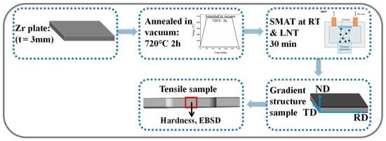
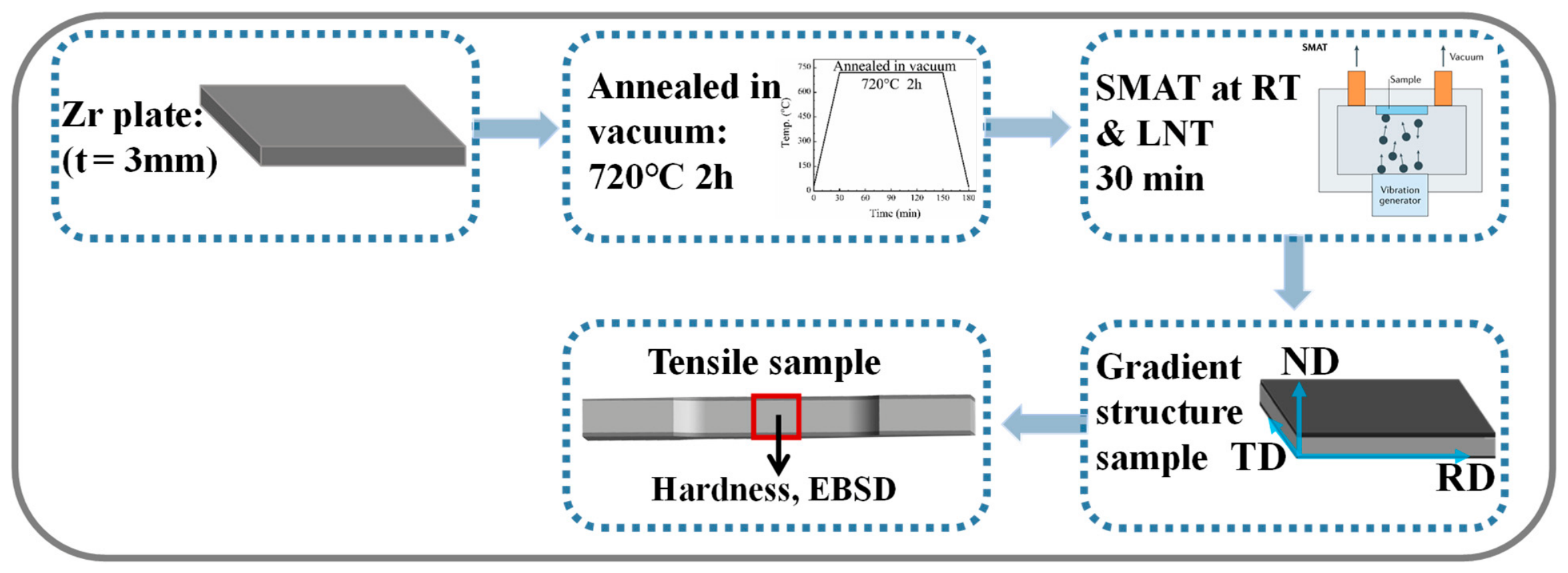
Microhardness on the RD-ND (ND: normal direction) plane of the samples was measured using a Vickers microhardness tester (HVST-1000Z, Kunming, China) at a load of 500 g and a dwell time of 15 s, with a spacing of 40 μm between adjacent indentations. The final microhardness at each depth was averaged from five indentations. Mechanical properties of Zr specimens were investigated by quasi-static tensile tests at a strain rate of 1 × 10⁻³ s−1 at RT. Dog-bone-shaped tensile samples, with a gauge dimension of 15 mm × 5 mm × 3 mm (L × W × H), were prepared by wire-electrode cutting (DK7732C, Kunming, China). Three samples were tested under each condition to ensure reproducibility. The processing route and sampling positions for microstructure observation are illustrated in Figure 1.
Figure 1.
Schematic illustration of the processing route for pure Zr. RD: rolling direction, TD: transverse direction, ND: normal direction. The red square shows the sampling location for the microhardness and EBSD analysis.
3. Results and Discussion
3.1. Microstructure Characterization
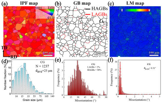
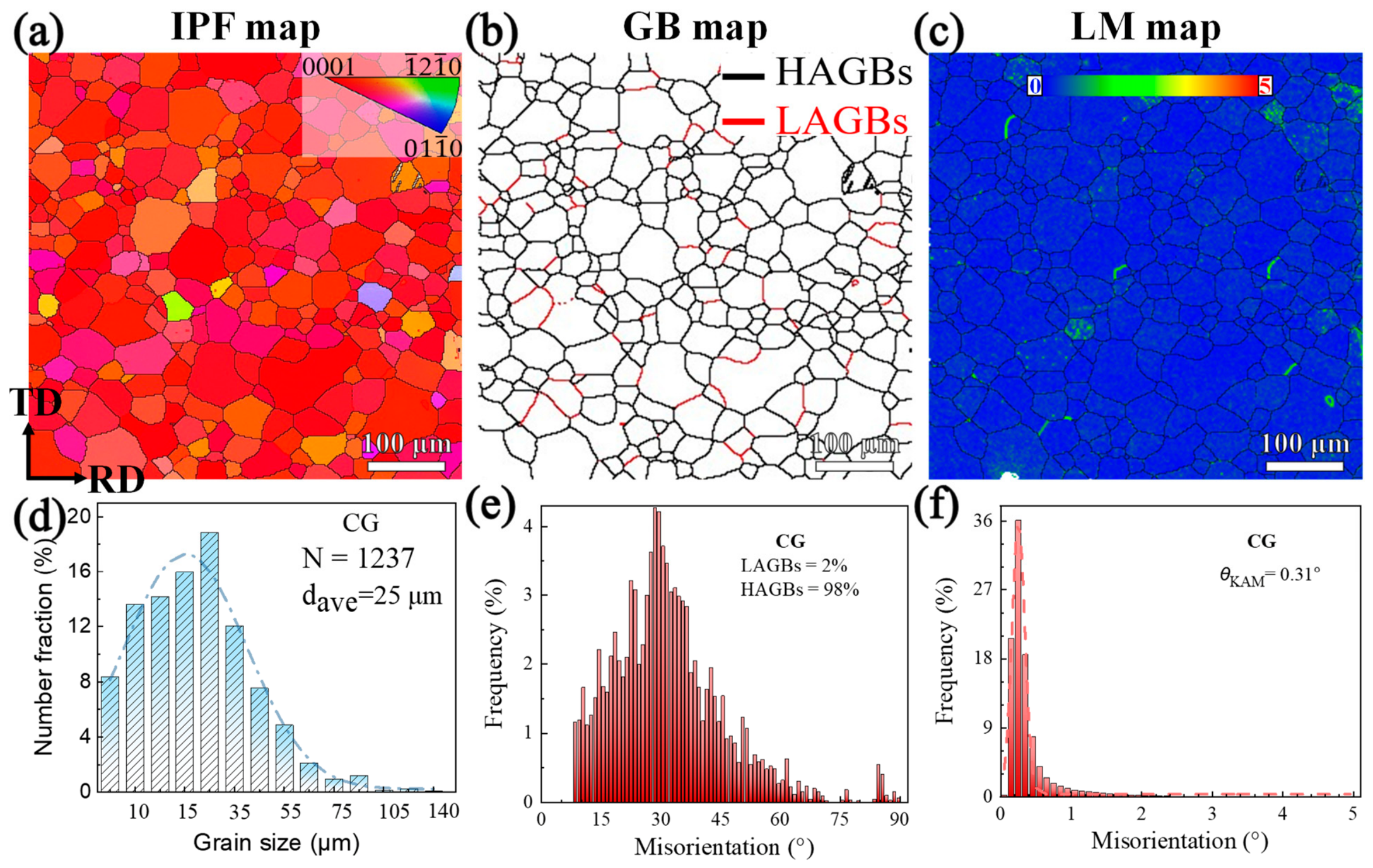
The microstructures of the CG sample characterized by EBSD are exhibited in Figure 2. Figure 2a shows the EBSD inverse pole figures (IPF), with the color code provided in the inset. Red, blue, and green correspond to grains oriented with <0001>, <010>, and <20> axes parallel to the ND, respectively. The IPF maps reveal a homogeneous, twin-free CG microstructure after annealing. The predominance of red-colored grains means a strong basal texture, i.e., the <0001> axis is preferentially aligned parallel to the ND. In addition, the grain size distribution in Figure 2d further indicates that the mean grain size of the CG sample is approximately 25 μm.
Figure 2.
EBSD characterization of the CG Zr microstructure: (a) IPF map; (b) GB map; (c) LM map; (d) grain size distribution; (e) GB misorientation distribution; (f) LM distribution.
The grain boundary (GB) map of CG is presented in Figure 2b, where black and red lines correspond to high-angle grain boundaries (HAGBs, >10°) and low-angle grain boundaries (LAGBs, 2°~10°), respectively. Misorientations below 2° arising from orientation noise during sampling are excluded. The misorientation angle distributions (MADs) in Figure 2e confirm that the majority of grain boundaries are HAGBs, with LAGBs constituting only 2% of the total in the CG sample. The local misorientation (LM) map of the CG sample, reflecting the accumulation of GNDs [42], is shown in Figure 2c. The color code bar in the inset delineates the misorientation level. Red points signify a large misorientation of 3–5° relative to the surrounding points, while green and blue points denote misorientations of 1–3° and <1°, respectively. The color variation is negligible, with the map being predominantly blue. In addition, the local misorientation distribution (LMD) in Figure 2f displays a narrow peak, and the Kernel average misorientation (θKAM) is merely 0.31°, implying a low density of GNDs within the grains. The θKAM serves as an indicator of the local lattice curvature originating from the accumulation of GNDs from rolling [43]. To preclude artifacts from adjacent GBs, misorientations exceeding 5° are excluded.
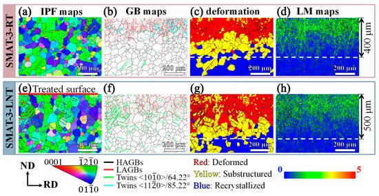
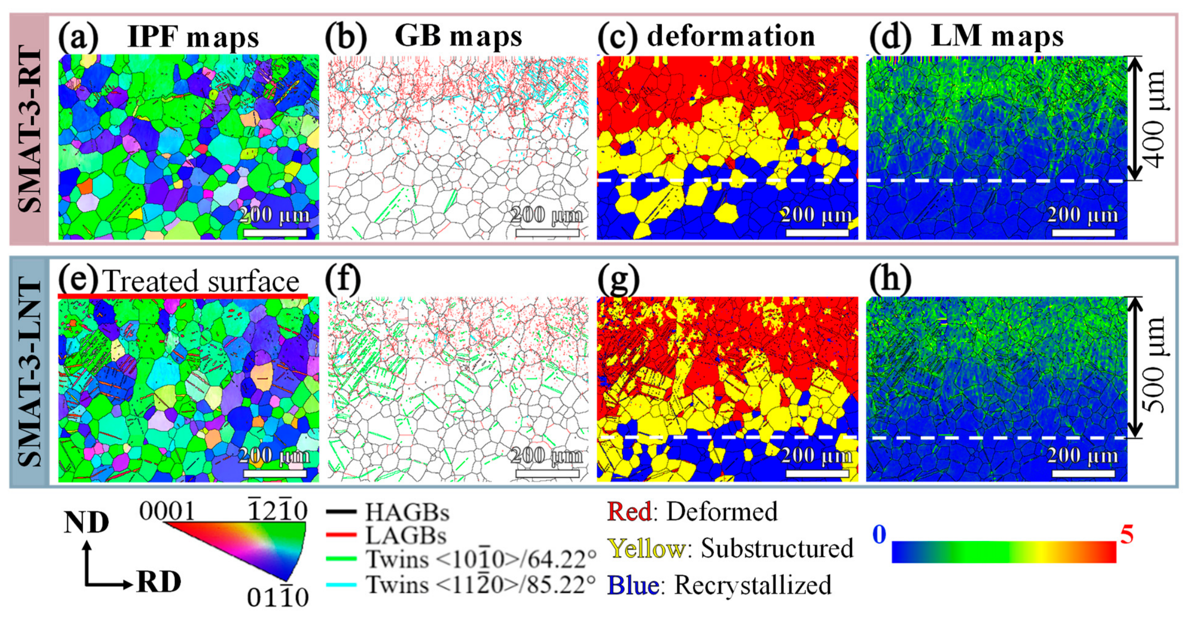
Figure 3a,e present the cross-sectional IPF maps for the SMAT-3-RT and SMAT-3-LNT samples, respectively. The color code beneath the maps indicates that red, blue, and green denote the grains oriented with <0001>, <010>, and <20> axis parallel to the TD, respectively. The majority of grains appear green or blue, demonstrating a preferential orientation of <20> and <010> axes parallel to the TD. Interestingly, deformation twins are observed in both samples, with a remarkably higher incidence in the SMAT-3-LNT sample. This finding suggests that deformation twinning constitutes a significant deformation mechanism during the SMAT process, particularly pronounced at low temperatures.
Figure 3.
EBSD characterization of (a–d) SMAT-3-RT and (e–h) SMAT-3-LNT samples: (a,e) IPF maps; (b,f) GB maps; (c,g) deformed, substructured, and recrystallized grain maps; (d,h) LM maps.
The GB maps (Figure 3b,f) reveal that black and red lines correspond to HAGBs and LAGBs, respectively. The green lines represent {112} <11> (C1) twin boundaries, which reorient the Zr lattice by 64.22° about the <010> axis, while the sky-blue lines represent {102} <10> (T1) twin boundaries, reorienting the lattice by 85.22° about the <110> axis. Remarkably, the SMAT-3-RT sample contains numerous LAGBs and T1 twin boundaries, whereas the SMAT-3-LNT sample exhibits abundant LAGBs and C1 twin boundaries. This observation confirms that deformation twinning serves as the primary deformation mechanism during the SMAT process, albeit with different twin types activated at different processing temperatures. The underlying mechanisms will be discussed later.
The deformed, substructured, and recrystallized grain distributions for the SMAT-3-RT and SMAT-3-LNT samples are displayed in Figure 3c,g, respectively, based on the internal average misorientation angle [42]. This approach is commonly employed to investigate recrystallization behavior from EBSD data [44,45]. Red regions denote “deformed” grains, characterized by an average misorientation angle exceeding 2° due to substantial dislocation accumulation. Yellow regions correspond to “substructured” grains, with an internal average misorientation below 2°. Blue regions represent “recrystallized” grains, which exhibit negligible internal misorientation as a result of minimal deformation. It is noteworthy that the grain distributions in both the MAT-3-RT and SMAT-3-LNT samples exhibit a transition from deformed grains to substructured grains, and finally to recrystallized grains, as the thickness increases from the treated surface to the core. Based on the deformed grain regions, the severe deformation layers for the SMAT-3-RT and SMAT-3-LNT samples are approximately 250 μm and 320 μm, respectively, suggesting that more pronounced plastic deformation occurs at low temperature during the SMAT process. In the transition layers, all grains are substructured, implying lower plastic deformation. In contrast, the recrystallized grains in cores originate from the CG sample, which remained undeformed during the SMAT process. Figure 3d,h show the LM maps of the SMAT-3-RT and SMAT-3-LNT samples, respectively. Within the deformed layers, yellow and green are the predominant colors, signifying a substantial increase in GNDs during the SMAT process, while the undeformed grains remain blue. The EBSD data further corroborate the formation of a gradient microstructure from the surface to the core after SMAT. Integration of the grain distributions and LM map data indicates that the gradient layer, encompassing both the deformation and transition layers, has a thickness of approximately 400 μm for the SMAT-3-RT samples and 500 μm for the SMAT-3-LNT samples.
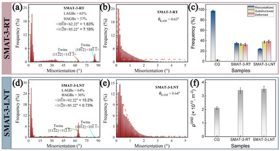
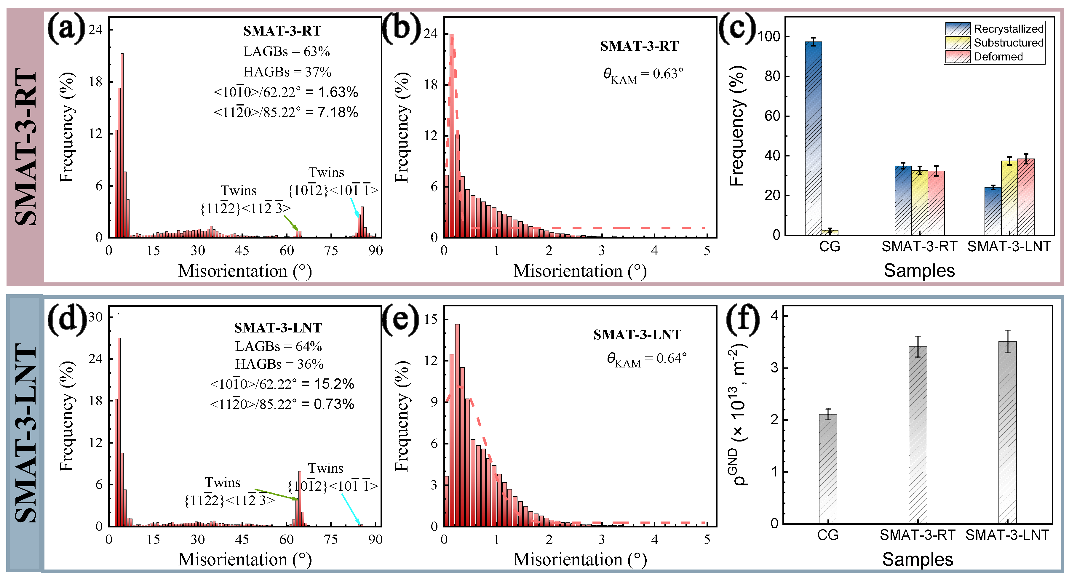
Figure 4a,d exhibit the grain boundary misorientation angle distributions for the SMAT-3-RT and SMAT-3-LNT samples, respectively. Relative to the CG counterpart, the SMAT-ed samples display a lower proportion of HAGBs and a correspondingly higher fraction of LAGBs, implying grain refinement during the SMAT process. The SMAT-3-RT sample comprises 63% LAGBs and 37% HAGBs, alongside 1.63% C1 compression twins and 7.18% T1 tensile twins. Conversely, the SMAT-3-LNT sample consists of approximately 64% LAGBs and 36% HAGBs, with 15.2% C1 compression twins and 0.73%. T1 tensile twins. Significantly, the LAGBs and HAGBs fractions are similar in both SMAT-ed samples, but the SMAT-3-LNT sample exhibits a higher total twin fraction, manifesting a greater plastic deformation at low temperature. Additionally, grain type analysis (Figure 4c) reveals a higher fraction of deformed grains in the SMAT-3-LNT samples.
Figure 4.
(a,d) GB misorientation angle distributions of the SMAT-3-RT and SMAT-3-LNT samples, respectively; (b,e) LM distributions of the SMAT-3-RT and SMAT-3-LNT samples, respectively; (c) fractions of recrystallized, substructured, and deformed grains; and (f) average GND density of the SMAT-treated samples.
Figure 4b,e present the local misorientation distributions (LMDs) of the SMAT-3-RT and SMAT-3-LNT samples, respectively. Both SMAT-ed samples exhibit similar LM distributions, with a θKAM of ~0.63°. Compared to the CG counterpart, the SMAT-ed samples show a broader LM distribution, where θKAM increases from 0.31° to 0.63°, indicating an increase in the GND density. Moreover, the average density of GNDs (ρGND) for the CG and SMAT-ed samples is displayed in Figure 4f. The quantitative calculations of θKAM and ρGND are also listed in Table 2, where θKAM is calculated as θKAM = ∑ fi θi (θ < 5°), in which θi and fi represent the local misorientation and its frequency, respectively. In addition, the ρGND is given by ρGND = 2θKAM/X · b, where X and b denote the step size in EBSD and the Burgers vector of pure Zr, respectively [46]. The calculated GND density is higher in the SMAT-ed samples than in the CG counterparts; however, the increase is not significant.
Table 2.
The step size (X), θKAM, and average ρGND for SMAT-ed samples from the EBSD results.
It is noteworthy that the microstructural evolution was characterized using EBSD with a step size of 2 µm, constraining the resolution of surface nanotwins. However, it adequately captured the overall gradient structure and sub-surface features. Consequently, the θKAM is interpreted as a qualitative relative metric of lattice distortion. Given identical processing and analysis conditions across samples, these metrics reliably reflect comparative differences in deformation mechanisms induced by temperature.
3.2. Microhardness Analysis
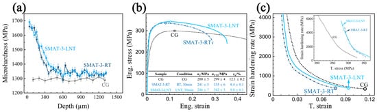
The cross-sectional microhardness distribution along the thickness of CG and SMAT-ed samples is shown in Figure 5a. Compared to the CG samples (1300 ± 35 MPa), the surface microhardness of the SMAT-ed samples increases significantly, reaching 1660 ± 32 MPa for the SMAT-3-RT samples and 1690 ± 23 MPa for the SMAT-3-LNT samples. Concurrently, the microhardness of the SMAT-ed samples gradually decreases with increasing depth from the surface to the core, forming a distinct hardness gradient. This gradient can be ascribed to the progressively decreasing strain and strain rate from the surface to the core during the SMAT process, which results in a gradient microstructure. The highest strain rate on the treated surface induces severe plastic deformation, where the accumulation of dislocations and twins leads to the maximum surface hardness. Based on the microhardness distribution along the depth, the gradient layer thicknesses are approximately 400 μm for the SMAT-3-RT samples and 500 μm for the SMAT-3-LNT samples, consistent with the observed microstructure. The corresponding volume fractions of the gradient layers are approximately 26.7% and 33.3% for the SMAT-3-RT and SMAT-3-LNT samples, respectively. Previous studies [47] have demonstrated that the volume fraction of the gradient layer significantly influences the mechanical properties of samples.
Figure 5.
Mechanical properties of the CG and SMAT-ed samples: (a) cross-sectional microhardness distribution from the surface to the core; (b) engineering stress–strain curves, with the tensile properties of samples listed in the inset tables (the symbol (○) indicates the ultimate tensile strength); (c) corresponding strain hardening rate curves as a function of true strain and the Kocks–Mecking plot in the inset.
3.3. Tensile Properties
The engineering stress-strain curves of the CG and SMAT-ed samples, tensioned along RD at RT, are displayed in Figure 5b. Meanwhile, the yield strength (σy), ultimate tensile strength (σUTS), together with uniform elongation (εu), are illustrated in the inserted table. The CG sample exhibits a yield strength of ~200 MPa, an ultimate tensile strength of ~299 MPa, and a uniform elongation of ~12.1%. Compared to the CG sample, both the SMAT-3-RT and SMAT-3-LNT samples show improved yield and ultimate tensile strengths, approximately 40–50 MPa higher, which correlates well with their comparable GND densities. This indicates that dislocation strengthening is the dominant mechanism for the observed strength improvement in both SMAT-ed samples. However, while uniform elongation decreases slightly after SMAT, the SMAT-3-LNT samples retain significantly greater ductility than the SMAT-3-RT samples, achieving a superior strength–ductility combination.
It is important to note that mechanical properties reflect the composite response of the gradient microstructure, consisting of the hardened surface layer and the coarse-grained core. During tensile testing, heterogeneous deformation occurs: the harder surface yields first, generating GNDs and HDI at the interface to accommodate the strain gradient [7,9]. The difference in uniform elongation arises from the deformation compatibility, which is governed by the gradient layer thickness and twin density. While twin boundaries in both SMAT-ed samples enhance local work-hardening, the SMAT-3-LNT sample exhibits a significantly thicker gradient layer with a higher volume fraction of twins. This optimized structure mitigates stress concentrations at the interface and delays premature necking.
The strain hardening rate (Θ = dσ/dε, σ: true stress, ε: true strain) decreases monotonically with increasing true strain, as exhibited in Figure 5c. Specifically, the rapid initial drop in Θ is related to a lack of mobile dislocations at the onset of plastic deformation, whereas the subsequent gradual decrease results from the continuous accumulation and storage of dislocations during straining [48]. As illustrated in Figure 5c, the strain hardening rate of the SMAT-3-LNT sample declines more gradually than that of the SMAT-3-RT sample, thereby leading to a higher uniform elongation. Moreover, the strain hardening rate versus true stress (σ), known as the Kocks–Mecking plot, is shown in the inset of Figure 5c. Specifically, the SMAT-3-LNT sample exhibits a slower decay rate than the SMAT-3-RT sample, which correlates with the higher density of deformation twins acting as effective barriers for dislocation motion. This superior strain hardening capacity is attributed to the optimized gradient layer thickness and the higher volume fraction of twins in the SMAT-3-LNT sample.
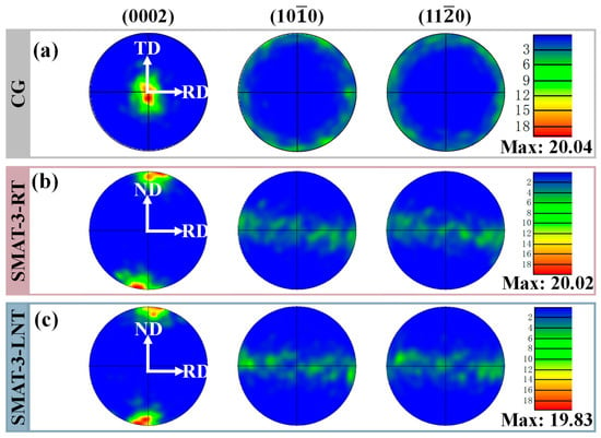
Texture is an important factor affecting the mechanical properties of HCP materials. To investigate its effect on the mechanical properties of pure Zr, the {0002}, {100}, and {110} pole figures (PFs) characterizing the texture are shown in Figure 6. All samples exhibit a similarly strong basal texture, i.e., the <c> axes of most grains are aligned parallel to the ND, with comparable maximum texture intensities. This can result from the fact that severe plastic deformation is confined to a depth of approximately 400~500 μm from the surface during the SMAT process, while the remaining sample retains the initial CG structure, exerting little influence on the overall texture.
Figure 6.
PF maps and texture intensities of the samples: (a) CG; (b) SMAT-3-RT; (c) SMAT-3-LNT.
Both the texture components and intensities of the SMAT-ed samples are identical to those of the CG specimen, indicating an equivalent influence of texture on their mechanical properties. Hence, the enhanced strength and retained ductility of the two SMAT-ed samples are unrelated to texture variations. Rather, these mechanical responses stem primarily from the unique gradient structure, which promotes incompatibility of plastic deformation during tension, generating abundant GNDs and resulting in HDI strengthening and strain hardening [49]. Furthermore, the superior strength–ductility balance achieved in the SMAT-3-LNT samples, compared to the SMAT-3-RT samples, can be mainly ascribed to their appropriate gradient layer thickness and higher volume fraction of twins, which effectively preserve ductility.
3.4. Deformation Mechanism
Plastic deformation of HCP pure Zr is primarily accommodated by dislocation slip and deformation twinning [24,50,51,52,53]. The deformation mechanisms during the SMAT process and subsequent tension are elucidated based on analyses of the microstructure, SF, and critical resolved shear stress (CRSS) for slip activation. A higher SF means a greater probability of activating a given slip or twinning system.
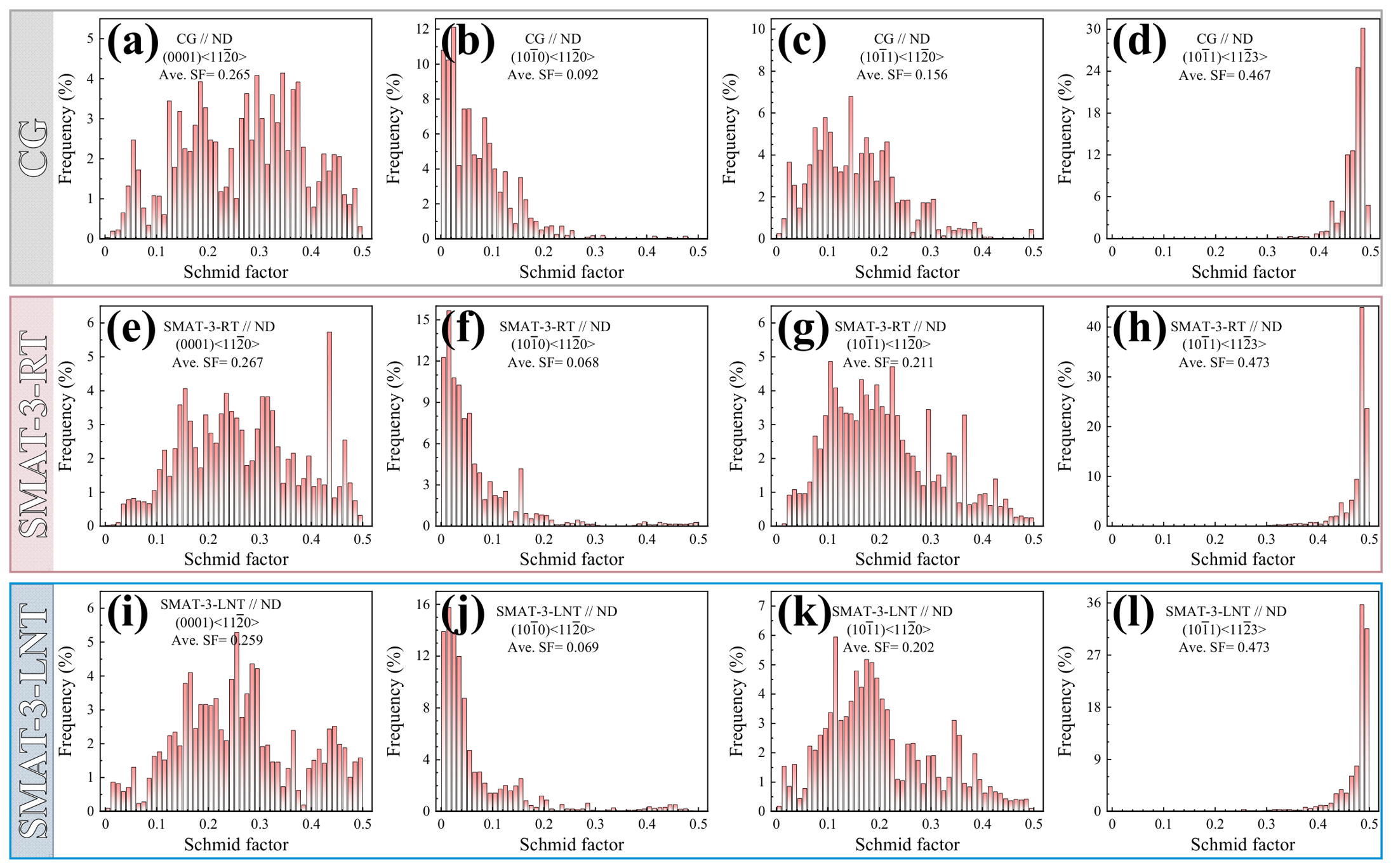
The microstructures observed via EBSD (Figure 3) show that deformation twins and increased GND density are present in both SMAT-3-RT and SMAT-3-LNT samples, confirming that dislocation slip and deformation twinning are both activated during SMAT. Figure 7 illustrates the SF distribution maps of various slip systems along the ND for the CG and SMAT-ed samples. In the CG samples, the pyramidal (Pyr) <> dislocation slip exhibits the highest average SF (~0.467), whereas prismatic slip has the lowest average SF (~0.092), suggesting that the Pyr <> slip is most readily activated during SMAT, while the prismatic <> slip is least favored. After SMAT, the average SFs of the various slip systems in the SMAT-3-RT and SMAT-3-LNT samples reflect little difference from each other but differ markedly from those of the CG sample. Compared with the CG sample, the average SFs for Pyr <a> and Pyr <c + a> slip increase to ~0.21 and ~0.473, respectively, whereas that for prismatic slip decreases to ~0.068, and that for basal slip remains largely unchanged. This demonstrates that grain orientation during SMAT progressively favors the activation of the two pyramidal slip systems while further suppressing prismatic slip. Nevertheless, the unchanged texture components and intensity reveal that the extent of grain reorientation is limited.
Figure 7.
The SF distributions of four slip systems along ND in the samples during the SMAT process: (a–d) CG; (e–h) SMAT-3-RT; (i–l) SMAT-3-LNT.
However, besides the crucial parameter of SF, the critical resolved shear stress (CRSS)—the minimum shear stress required to activate a given slip system [54]—is another key factor governing slip system activation. The CRSS values of different slip systems of pure Zr reported in the literature [50,55,56,57] are listed in Table 3, among which prismatic slip shows the lowest CRSS, whereas Pyr <c + a> slip has the highest CRSS (~twice that of prismatic slip). Notably, the CRSS ranking is opposite to that of the SF results in Figure 7. Therefore, whether a slip system is activated during plastic deformation cannot be judged by SF alone but must be evaluated by considering both factors. According to Schmid’s law, the applied stress (σapplied) required to activate a slip system is related to its average SF (mave) and the CRSS (σCRSS) as follows [43,58]: σapplied = σCRSS/mave. Using the σCRSS from Ref. [56], the calculated stresses required to activate different slip systems in pure Zr during SMAT for all samples are summarized in Table 4. The applied stress required to activate basal slip is the lowest, whereas that for prismatic slip is the highest, with the two pyramidal slips in between. However, as SMAT progresses, the activation stress for Pyr <a> slip becomes the lowest, while that for prismatic slip increases further. Despite being the intrinsically easiest system, prismatic slip exhibits the highest activation stress due to unfavorable crystallographic orientations imposed by the strong basal texture. Due to the low symmetry of the HCP crystal structure, slip system activation is highly sensitive to crystal orientation (texture) [59]. Specifically, grains with their <c>-axis nearly perpendicular to the applied uniaxial stress are termed ‘soft grains,’ facilitating prismatic slip. Conversely, ‘hard grains,’ characterized by a <c>-axis parallel to the loading direction, typically deform via basal or pyramidal slips or deformation twinning [50,60,61]. Therefore, the basal <a> and Pyr<a> dislocations are preferentially activated during deformation. Although basal <a> slip is generally difficult to activate at RT, the high strain and strain rate induced by SMAT facilitate its operation. As a consequence, the GNDs in the SMAT-ed samples are primarily composed of basal <a> and Pyr <a> dislocations.
Table 3.
CRSS (MPa) values of different slip systems in pure Zr from the literature.
Table 4.
The σapplied (MPa) required to activate slip systems along ND in the samples during the SMAT process.
While we acknowledge that average SF derived from EBSD maps assumes a homogeneous stress field and thus cannot capture local stress fluctuations induced by GNDs in gradient structures, this approach remains valid for identifying deformation trends. However, the absolute activation stresses may deviate from the local stress due to heterogeneities.
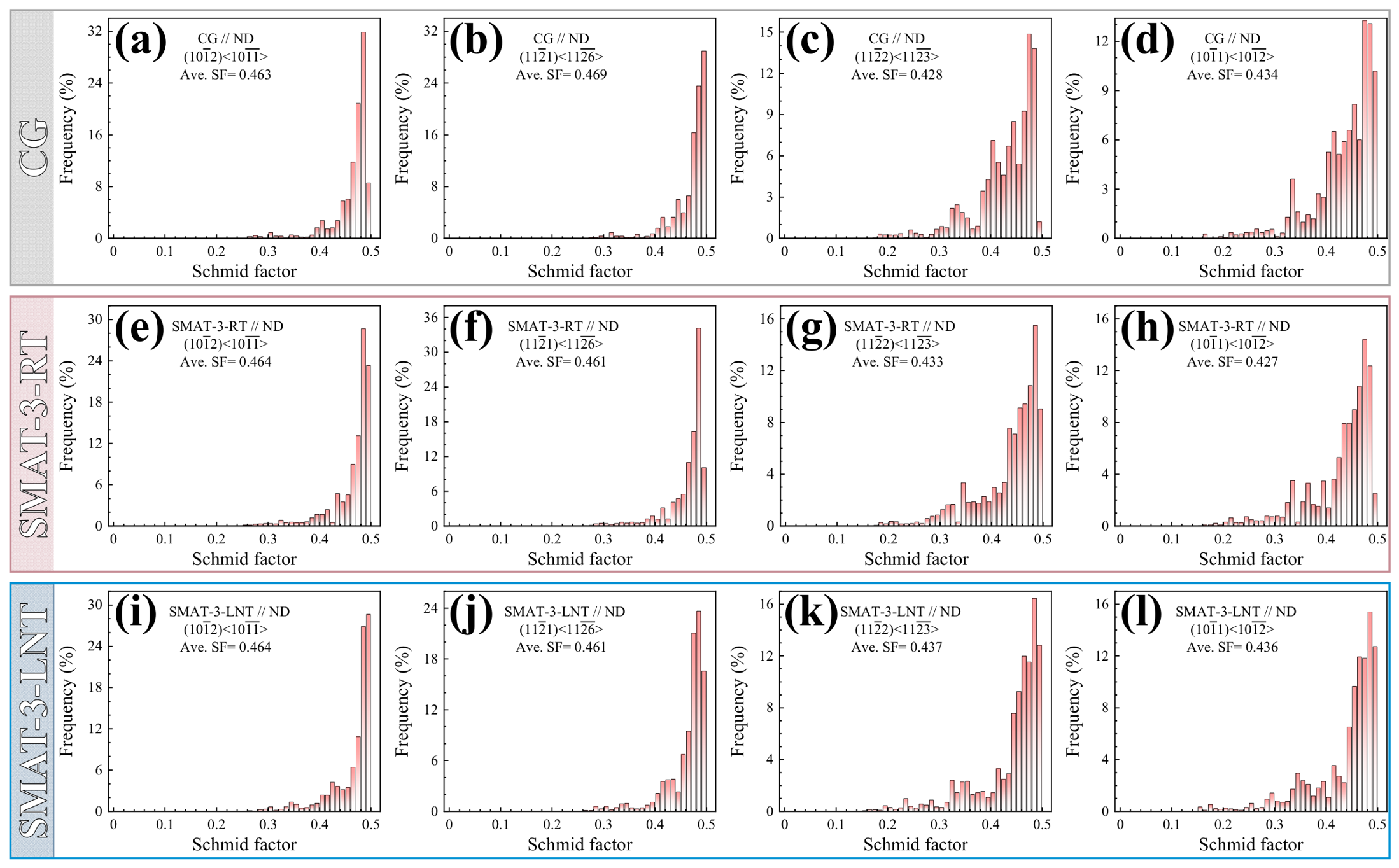
Figure 8 presents the SF distributions of various twin systems along the ND in the CG and SMAT-ed samples. Tension twins exhibit marginally higher average SFs than compression twins (ΔSF ≈ 0.025–0.035), implying broadly comparable formation probabilities with a slight preference for tension twins. The average SFs are largely similar between the two SMAT-ed samples, except for slightly higher compression twin values in the SMAT-3-LNT sample. Compared with the CG sample, SMAT negligibly affects the tension twin SFs but increases the average SF of the C1 compression twin, indicating an enhanced probability of C1 twin formation with continued deformation.
Figure 8.
SF distributions of four twinning systems along ND for samples during the SMAT process: (a–d) CG; (e–h) SMAT-3-RT; (i–l) SMAT-3-LNT.
In addition to SF, the formation of twins depends on the required macroscopic shear strain—the larger the strain, the more difficult the activation. Table 5 lists the macroscopic shear strains required for the formation of various twins in pure Zr reported in the literature [62,63,64,65]: C2 compression twinning requires the minimum, followed by T1 tension twinning, whereas T2 tension twinning requires the maximum. Integrating the SF distributions with the shear strain requirements, the expected ease of twin formation during SMAT follows the sequence C2 > T1 > C1 > T2. However, no C2 twins are observed after SMAT at either RT or LNT; instead, T1 and C1 twins with varying volume fractions are detected. This discrepancy can be attributed to the typical activation of C2 twinning only at elevated temperatures [25], accounting for its absence in the present SMAT-ed samples.
Table 5.
The macroscopic shear strains for different twinning modes in pure Zr from the literature.
In summary, the limited activation of dislocation slip renders deformation twinning the dominant strain accommodation mode during the SMAT process, consistent with previous reports that twinning prevails under low-temperature and/or high-strain-rate conditions [66]. The high-velocity ball impacts promote twin formation at both RT and LNT during SMAT. The presence of both T1 and C1 twins in the SMAT-3-RT and SMAT-3-LNT samples demonstrates that the shear strains for activating these twin systems are supplied by SMAT. However, the SMAT-3-RT sample exhibits a higher volume fraction of T1 twins, owing to their relatively low macroscopic shear strain and ready activation across wide temperature and strain rate ranges [25]. Consequently, the gradient structure at RT is accommodated primarily by basal <> and Pyr <> dislocation slip, together with T1 twinning. In contrast, the higher fraction of C1 compression twins in the SMAT-3-LNT sample arises from the temperature sensitivity of C1 twinning, which is favored at LNT rather than RT [25]. Accordingly, the low-temperature gradient structure is accommodated mainly by basal <a> and Pyr <a> slip together with C1 twinning.
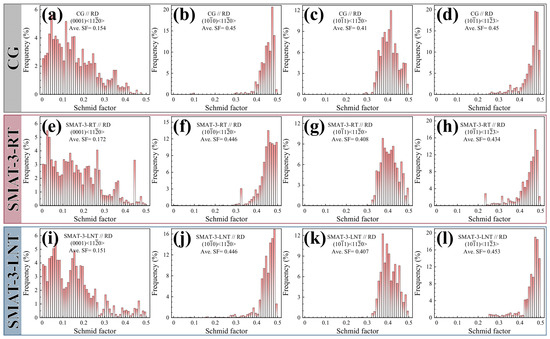
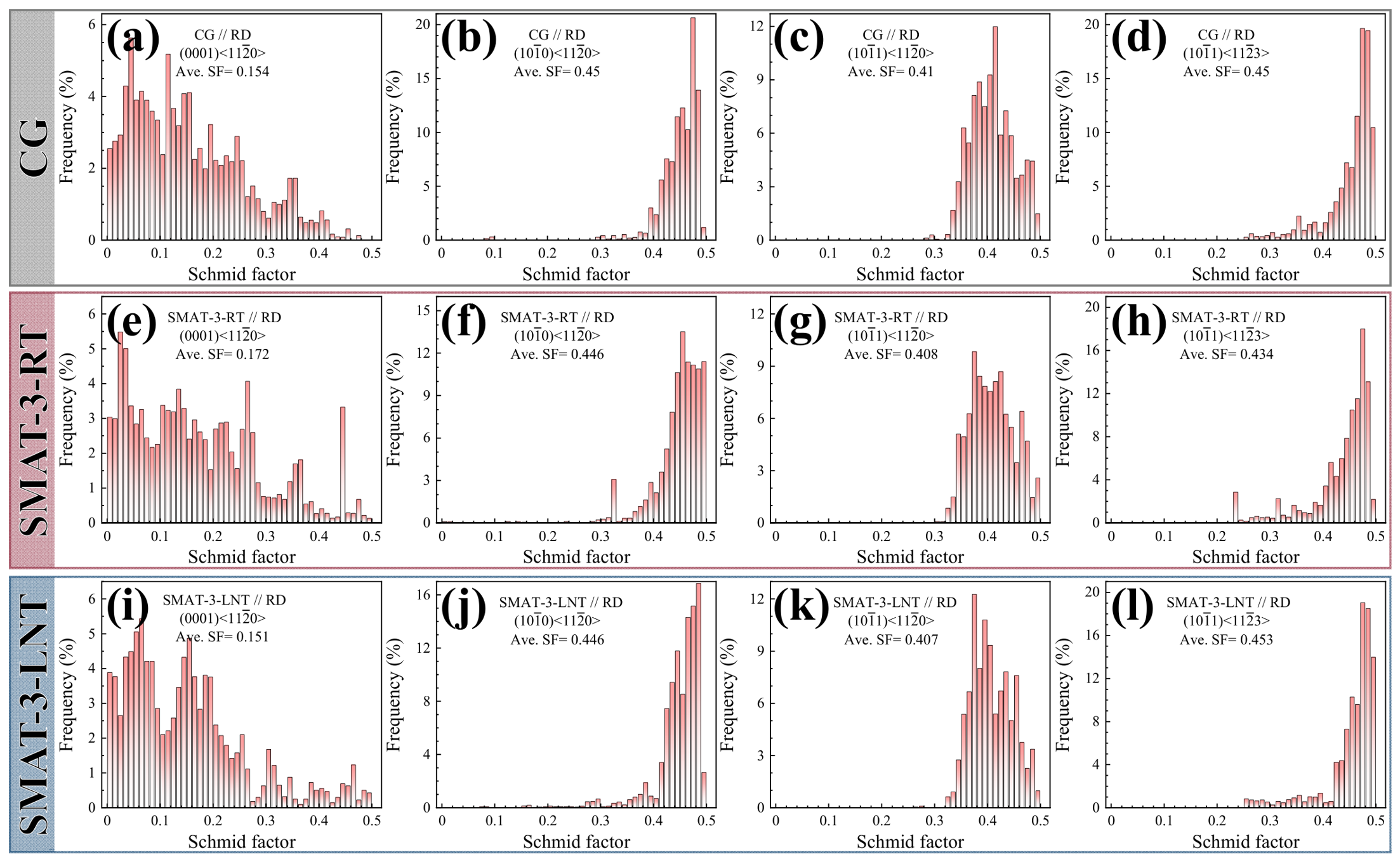
The SF distributions of various slip systems along the RD (tensile axis) for the CG and SMAT-ed samples are shown in Figure 9. The prismatic <a> and pyr <c + a> slips display comparable mean SF values across all samples, while basal slip shows the lowest value, implying the highest and lowest activation probabilities, respectively. Moreover, Table 6 shows that prismatic slip requires the minimum external stress for activation, followed by Pyr <a> slip, while Pyr <c + a> and basal slips demand substantially higher stresses. Therefore, prismatic <a> slip is expected to activate first among the slip systems in both CG and SMAT-ed samples, with basal <a> slip being the most unfavorable deformation mode under this loading condition. From the tensile properties (Figure 3), the flow stress in CG samples is sufficient to readily activate prismatic and Pyr <a> slips but remains well below the threshold for Pyr <c + a> slip. Although the moderate strength enhancement in SMAT-ed samples allows prismatic and Pyr <a> slips to dominate the deformation, the inherent deformation inhomogeneity of the gradient structure potentially creates localized high-stress regions capable of triggering minor fractions of Pyr <c + a> slip. Ultimately, prismatic slip dominates the tensile deformation of the SMAT-ed samples.
Figure 9.
SF distributions of four slip systems along RD for samples during tensile deformation: (a–d) CG; (e–h) SMAT-3-RT; (i–l) SMAT-3-LNT.
Table 6.
The σapplied (MPa) required to activate slip systems along the RD in CG and GS Zr during tension.
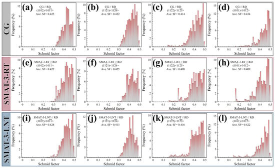
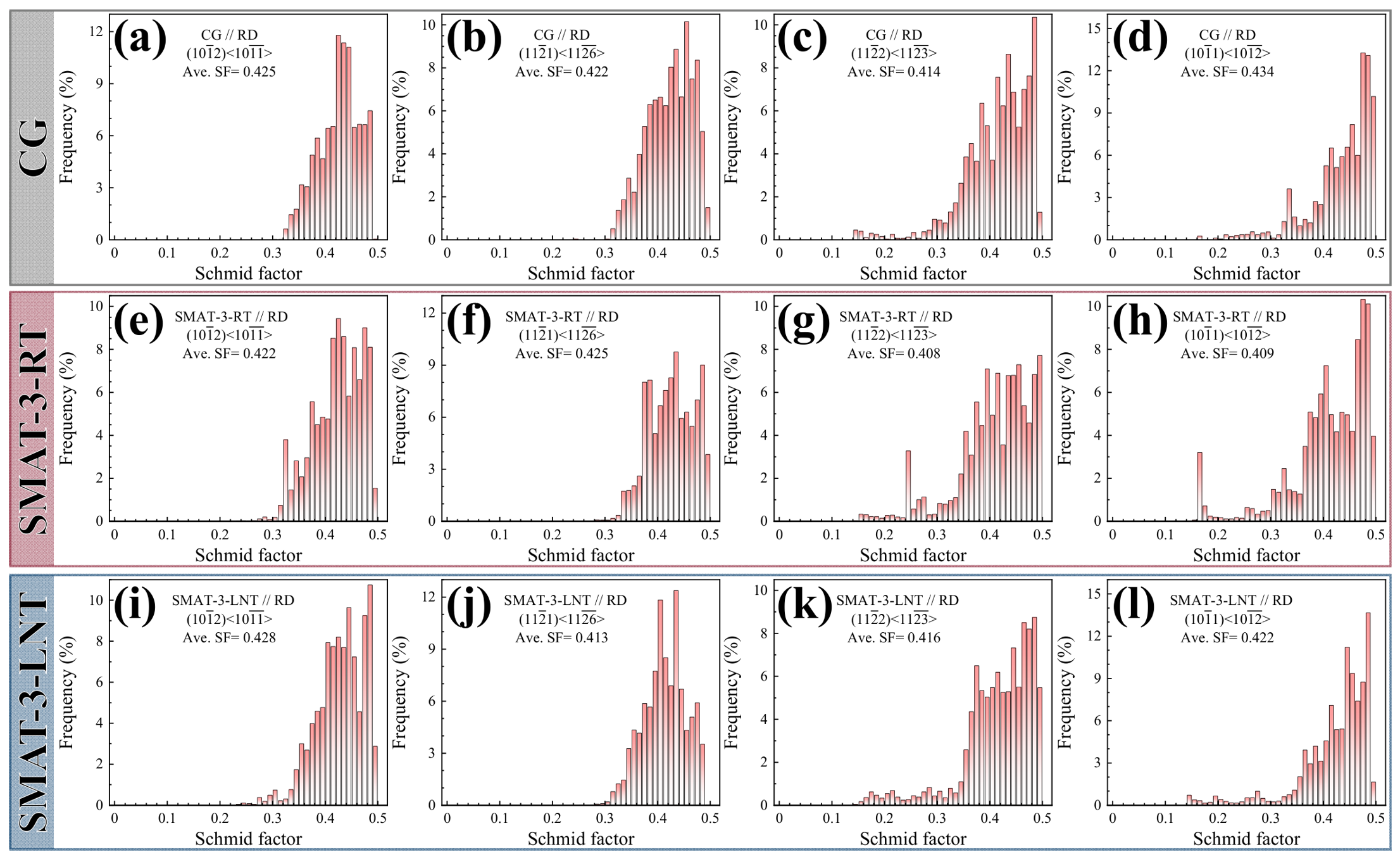
The SF distributions of various twin systems along the tensile direction for the CG and SMAT-ed samples during tension are exhibited in Figure 10. The mean SFs of all twin systems are comparable among the samples, ranging from 0.41 to 0.43. However, these values are lower than those along the ND direction, meaning a reduced probability of twinning. Moreover, the tensile tests were conducted at RT with a strain rate of 1 × 10⁻³ s−1—neither cryogenic nor high-strain-rate conditions. Under such conditions, prismatic slip was readily activated, whereas deformation twinning was unlikely to occur.
Figure 10.
SF distributions of four twinning systems along RD for samples during tensile deformation: (a–d) CG; (e–h) SMAT-3-RT; (i–l) SMAT-3-LNT.
Therefore, both the CG and SMAT-ed samples deform predominantly via prismatic slip during tension. The superior strength and comparable ductility of the SMAT-ed samples relative to the CG sample are attributed to the HDI strengthening and hardening induced by the gradient-structured microstructure. The SMAT-3-LNT sample exhibits strength comparable to that of the SMAT-3-RT sample while achieving a better strength–ductility synergy, which is ascribed to its more optimized volume fraction of gradient layers and the higher twin fraction within the sample.
4. Conclusions
In brief, gradient-structured pure Zr was fabricated by SMAT at room temperature (RT) and liquid nitrogen temperature (LNT), and the influence of processing temperature on microstructural evolution, mechanical properties, and deformation mechanisms was systematically investigated. The key findings are as follows:
(1) Superior performance and process advantages: The SMAT-3-LNT samples exhibit a superior strength–ductility synergy, with yield strength increased by 23% and uniform elongation maintained at 81%, significantly outperforming both the CG and SMAT-3-RT counterparts. Unlike conventional shot peening, which often induces surface flaking due to tangential shear, SMAT utilizes normal impacts to create an intact gradient layer without material removal. This cost-effective strategy effectively overcomes the strength–ductility trade-off in pure Zr while preserving surface integrity.
(2) Mechanistic insight and design principle for HCP metals: Processing temperature governs twin variant selection. Basal <a> and prismatic <a> slip accompanied by T1 ({102} <10>) twinning are activated during the SMAT process at RT, whereas C1 ({112} <11>) twinning is activated at LNT. The higher density of C1 twins in LNT samples enhances HDI stress accumulation and work-hardening capacity. This finding provides a general design guideline for other HCP metals (e.g., Ti, Mg alloys): cryogenic-assisted surface treatment can be a universal strategy to activate non-basal twins, thereby optimizing deformation compatibility in materials with limited slip systems.
(3) Practical application guidelines: Based on the mechanical responses, we propose specific processing strategies: SMAT at LNT is recommended for high-load structural components requiring maximum strength and delayed necking, leveraging the superior work-hardening from C1 twins. Conversely, SMAT at RT may suffice for applications prioritizing formability or cost reduction, where moderate strengthening is adequate. Thus, tuning the processing temperature allows engineers to tailor the performance envelope of gradient HCP materials according to specific service conditions.
Author Contributions
Z.F.: Methodology, Data curation, Writing—original draft, Funding acquisition. X.L.: Data curation, Investigation, Visualization, Formal analysis. X.C.: Investigation, Visualization, Formal analysis. X.Z.: Supervision, Writing—review and editing. All authors have read and agreed to the published version of the manuscript.
Funding
The authors would like to acknowledge the financial support of the Yunnan Province Department of Education Research Fund [grant number 2024J0772]. The authors were also supported by the Special Basic Cooperative Research Programs of Yunnan Provincial Undergraduate Universities’ Association (grant number 202401BA070001-034) and the Kunming Institute Program [grant number YJL24027].
Data Availability Statement
The original contributions presented in the study are included in the article, further inquiries can be directed to the corresponding author.
Conflicts of Interest
The authors declare no conflicts of interest.
References
- Chen, J.; Han, Y.; Li, S.; Wei, Z.; Le, J.; Shi, H.; Huang, G.; Lu, W.; Zhang, D. Evading the strength and ductility trade-off dilemma in titanium matrix composites through designing bimodal grains and micro-nano reinforcements. Scr. Mater. 2023, 235, 115625. [Google Scholar] [CrossRef] [Scilit]
- Wu, S.W.; Wang, G.; Wang, Q.; Jia, Y.D.; Yi, J.; Zhai, Q.J.; Liu, J.B.; Sun, B.A.; Chu, H.J.; Shen, J.; et al. Enhancement of strength-ductility trade-off in a high-entropy alloy through a heterogeneous structure. Acta Mater. 2019, 165, 444–458. [Google Scholar] [CrossRef] [Scilit]
- Valiev, R.Z.; Islamgaliev, R.K.; Alexandrov, I.V. Bulk nanostructured materials from severe plastic deformation. Prog. Mater. Sci. 2000, 45, 103–189. [Google Scholar] [CrossRef] [Scilit]
- Zhou, Z.; Li, X.; Gong, Y.; Yang, J.; Li, C.; Sun, L.; Tan, Z.; Zhu, X. Mechanical properties and deformation behavior of gradient-structured Cu–Al–Zn alloys processed by SMAT at room and liquid-nitrogen temperatures. J. Mater. Res. Technol. 2026, 43, 1288–1297. [Google Scholar] [CrossRef] [Scilit]
- Ding, H.; Zeng, Y.; Qian, X.; Chen, M.; Feng, Z.; Ni, R.; He, S.; Yin, D. Nanoscale quantification of slip activity and pre-twin-assisted strength-ductility synergy in AZ31 Mg alloy at cryogenic temperatures. J. Magnes. Alloy. 2026, 24, 102235. [Google Scholar] [CrossRef] [Scilit]
- Sun, L.; Li, X.; Li, C.; Gong, Y.; Fu, Z.; Yang, J.; Quan, S.; Qin, S.; Zhu, X. Investigation of mechanical properties and microstructural evolution in pure Copper with dual heterostructures produced by surface mechanical attrition treatment. Metals 2024, 14, 1217. [Google Scholar] [CrossRef] [Scilit]
- Zhou, H.; Wu, X.; Srolovitz, D.; Zhu, Y. Designing heterostructured materials. Nat. Mater. 2026, 25, 366–372. [Google Scholar] [CrossRef] [Scilit]
- Yue, X.; Du, H.; Zhang, L.; Hou, L.; Wang, Q.; Wei, H.; Liu, X.; Wei, Y. Grain gradient refinement and corrosion mechanisms in metals through severe plastic deformation: Insights from Surface Mechanical Attrition Treatment (SMAT). Adv. Compos. Hybrid Mater. 2025, 8, 122. [Google Scholar] [CrossRef] [Scilit]
- Zhu, Y.T.; Wu, X.L. Heterostructured materials. Prog. Mater. Sci. 2023, 131, 101019. [Google Scholar] [CrossRef] [Scilit]
- Fan, J.T.; Zhu, L.L.; Lu, J.; Fu, T.; Chen, A.Y. Theory of designing the gradient microstructured metals for overcoming strength-ductility trade-off. Scr. Mater. 2020, 184, 41–45. [Google Scholar] [CrossRef] [Scilit]
- Qin, S.; Yang, M.; Jiang, P.; Wang, J.; Wu, X.; Zhou, H.; Yuan, F. Superior dynamic shear properties by structures with dual gradients in medium entropy alloys. J. Mater. Sci. Technol. 2023, 153, 166–180. [Google Scholar] [CrossRef] [Scilit]
- Wang, J.J.; Tao, N.R.; Lu, K. Revealing the deformation mechanisms of nanograins in gradient nanostructured Cu and CuAl alloys under tension. Acta Mater. 2019, 180, 231–242. [Google Scholar] [CrossRef] [Scilit]
- Wu, X.L.; Jiang, P.; Chen, L.; Zhang, J.F.; Yuan, F.P.; Zhu, Y.T. Synergetic strengthening by gradient structure. Mater. Res. Lett. 2014, 2, 185–191. [Google Scholar] [CrossRef] [Scilit]
- Wu, X.; Jiang, P.; Chen, L.; Yuan, F.; Zhu, Y.T. Extraordinary strain hardening by gradient structure. Proc. Natl. Acad. Sci. USA 2014, 111, 7197–7201. [Google Scholar] [CrossRef] [Scilit]
- Wu, X.; Yang, M.; Li, R.; Jiang, P.; Yuan, F.; Wang, Y.; Zhu, Y.; Wei, Y. Plastic accommodation during tensile deformation of gradient structure. Sci. China Mater. 2021, 64, 1534–1544. [Google Scholar] [CrossRef] [Scilit]
- Sun, Y.; Zhao, C.; Tang, H.; Bi, Y. Tribological Properties of Additively Manufactured Aluminum Alloy Subjected to Surface Mechanical Attrition Treatment. Lubricants 2026, 14, 342. [Google Scholar] [CrossRef] [Scilit]
- Yang, H.; Zhang, Z.; Shu, J.; Han, Y. Gradient nanostructure, enhanced surface integrity and fatigue resistance of Ti-6Al-7Nb alloy processed by surface mechanical attrition treatment. J. Mater. Sci. Technol. 2024, 188, 252–269. [Google Scholar] [CrossRef] [Scilit]
- Katiyar, L.K. Enhancing mechanical properties and wear resistance of dual phase steel through surface mechanical attrition treatment. Results Surf. Interfaces 2024, 17, 100332. [Google Scholar] [CrossRef] [Scilit]
- Yarar, E.; Erturk, A.T.; Karabay, S. Effect of Surface Mechanical Attrition Treatment on Surface Topography and Dry Sliding Wear Performance of AA7075-T6. Adv. Eng. Mater. 2024, 26, 2400501. [Google Scholar] [CrossRef] [Scilit]
- Zhu, Y.T.; Ameyama, K.; Anderson, P.M.; Beyerlein, I.J.; Gao, H.J.; Kim, H.S.; Lavernia, E.; Mathaudhu, S.; Mughrabi, H.; Ritchie, R.O.; et al. Heterostructured materials: Superior properties from hetero-zone interaction. Mater. Res. Lett. 2020, 9, 1–31. [Google Scholar] [CrossRef] [Scilit]
- Wang, S.; Hu, Z.; Huang, Z.; Gao, B.; Chen, X.; Hu, J.; Zhu, Y.; Li, Y.; Zhou, H. New deformation mechanism and strength-ductility synergy in pure titanium with high density twin. Int. J. Plast. 2024, 174, 103908. [Google Scholar] [CrossRef] [Scilit]
- Zhao, S.; Zhang, R.; Yu, Q.; Ell, J.; Ritchie, R.O.; Minor, A.M. Cryoforged nanotwinned titanium with ultrahigh strength and ductility. Science 2021, 373, 1363–1368. [Google Scholar] [CrossRef] [Scilit]
- Liu, W.; Deng, H.; Qi, J.; Zhang, X.; Liu, Y.; Zhao, Z.; Zhu, J.; Luo, H.; Yin, H.; Xiang, W.; et al. Heterogeneous CRSS evolution and multistage twinning in near β titanium alloys during tensile deformation at cryogenic temperature. Mater. Sci. Eng. A 2026, 961, 150198. [Google Scholar] [CrossRef] [Scilit]
- An, X.L.; Zhang, H.; Ni, S.; Ou, X.Q.; Liao, X.Z.; Song, M. Effects of temperature and alloying content on the phase transformation and {10-11} twinning in Zr during rolling. J. Mater. Sci. Technol. 2020, 41, 76–80. [Google Scholar] [CrossRef] [Scilit]
- Knezevic, M.; Zecevic, M.; Beyerlein, I.J.; Bingert, J.F.; McCabe, R.J. Strain rate and temperature effects on the selection of primary and secondary slip and twinning systems in HCP Zr. Acta Mater. 2015, 88, 55–73. [Google Scholar] [CrossRef] [Scilit]
- Bhattacharyya, D.; Cerreta, E.K.; McCabe, R.; Niewczas, M.; Gray, G.T.; Misra, A.; Tomé, C.N. Origin of dislocations within tensile and compressive twins in pure textured Zr. Acta Mater. 2009, 57, 305–315. [Google Scholar] [CrossRef] [Scilit]
- Cerreta, E.; Gray, G.T.; Hixson, R.S.; Rigg, P.A.; Brown, D.W. The influence of interstitial oxygen and peak pressure on the shock loading behavior of zirconium. Acta Mater. 2005, 53, 1751–1758. [Google Scholar] [CrossRef] [Scilit]
- Chen, X.; Zeng, Q.H.; He, W.J.; Liu, Q. Detwinning behavior in commercial pure zirconium during orthogonal re-compression after pre-compression and annealing. Mater. Sci. Eng. A 2019, 767, 138444. [Google Scholar] [CrossRef] [Scilit]
- Partridge, P.G. The crystallography and deformation modes of hexagonal close-packed metals. Metall. Rev. 1967, 12, 169–194. [Google Scholar] [CrossRef] [Scilit]
- Yoo, M.H. Slip, twinning, and fracture in hexagonal close-packed metals. Metall. Trans. A 1981, 12, 409–418. [Google Scholar] [CrossRef] [Scilit]
- Chapuis, A.; Liu, Q. Simulations of texture evolution for HCP metals: Influence of the main slip systems. Comput. Mater. Sci. 2015, 97, 121–126. [Google Scholar] [CrossRef] [Scilit]
- Pochettino, A.A.; Gannio, N.; Edwards, C.V.; Penelle, R. Texture and pyramidal slip in Ti, Zr and their alloys. Scr. Metall. Mater. 1992, 27, 1859–1863. [Google Scholar] [CrossRef] [Scilit]
- Kaschner, G.C.; Tome, C.N.; Beyerlein, I.J.; Vogel, S.C.; Brown, D.W.; McCabe, R.J. Role of twinning in the hardening response of zirconium during temperature reloads. Acta Mater. 2006, 54, 2887–2896. [Google Scholar] [CrossRef] [Scilit]
- Yan, F.K.; Liu, G.Z.; Tao, N.R.; Lu, K. Strength and ductility of 316L austenitic stainless steel strengthened by nano-scale twin bundles. Acta Mater. 2012, 60, 1059–1071. [Google Scholar] [CrossRef] [Scilit]
- Kumar, M.A.; Yu, T.; Wang, Y.; Jianzhong, Z.; McCabe, R.J.; Tomé, C.N.; Capolungo, L. Effect of dislocation slip and deformation twinning on the high-pressure phase transformation in Zirconium. Scr. Mater. 2024, 242, 115941. [Google Scholar] [CrossRef] [Scilit]
- Tomé, C.N.; Maudlin, P.J.; Lebensohn, R.A.; Kaschner, G.C. Mechanical response of zirconium—I. derivation of a polycrystal constitutive law and finite element analysis. Acta Mater. 2001, 49, 3085–3096. [Google Scholar] [CrossRef] [Scilit]
- McCabe, R.J.; Cerreta, E.K.; Misra, A.; Kaschner, G.C.; Tome, C.N. Effects of texture, temperature and strain on the deformation modes of zirconium. Philos. Mag. 2006, 86, 3595–3611. [Google Scholar] [CrossRef] [Scilit]
- Guo, D.F.; Li, M.; Shi, Y.D.; Zhang, Z.B.; Zhang, H.T.; Liu, X.M.; Zhang, X.Y. Effect of strain rate on microstructure evolutions and mechanical properties of cryorolled Zr upon annealing. Mater. Lett. 2012, 66, 305–307. [Google Scholar] [CrossRef] [Scilit]
- Zhang, L.; Han, Y. Twins formation and their role in nanostructuring of zirconium. Mater. Sci. Eng. A 2009, 523, 130–133. [Google Scholar] [CrossRef] [Scilit]
- Zhang, L.; Han, Y.; Lu, J. Nanocrystallization of zirconium subjected to surface mechanical attrition treatment. Nanotechnology 2008, 19, 165706. [Google Scholar] [CrossRef] [Scilit]
- Jiang, P.; Wei, Q.; Hong, Y.S.; Lu, J.; Wu, X.L. In situ synthesis of nanocrystalline intermetallic layer during surface plastic deformation of zirconium. Surf. Coat. Technol. 2007, 202, 583–589. [Google Scholar] [CrossRef] [Scilit]
- Mao, Q.Z.; Zhang, Y.S.; Liu, J.Z.; Zhao, Y.H. Breaking material property trade-offs via macrodesign of microstructure. Nano Lett. 2021, 21, 3191–3197. [Google Scholar] [CrossRef] [Scilit]
- Meng, A.; Chen, X.; Nie, J.; Gu, L.; Mao, Q.; Zhao, Y. Microstructure evolution and mechanical properties of commercial pure titanium subjected to rotary swaging. J. Alloys Compd. 2021, 859, 158222. [Google Scholar] [CrossRef] [Scilit]
- Yu, P.F.; Wu, C.S.; Shi, L. Analysis and characterization of dynamic recrystallization and grain structure evolution in friction stir welding of aluminum plates. Acta Mater. 2021, 207, 116692. [Google Scholar] [CrossRef] [Scilit]
- Zhou, L.; Chen, S.; Ma, M.; Jing, L.; Chen, J.; Wang, M. The dynamic recrystallization mechanism of ultrasonic power on non-contact ultrasonic-assisted direct laser deposited alloy steel. Mater. Sci. Eng. A 2022, 840, 142971. [Google Scholar] [CrossRef] [Scilit]
- Calcagnotto, M.; Ponge, D.; Demir, E.; Raabe, D. Orientation gradients and geometrically necessary dislocations in ultrafine grained dual-phase steels studied by 2D and 3D EBSD. Mater. Sci. Eng. A 2010, 527, 2738–2746. [Google Scholar] [CrossRef] [Scilit]
- Yang, X.C.; Ma, X.L.; Moering, J.; Zhou, H.; Wang, W.; Gong, Y.L.; Tao, J.M.; Zhu, Y.T.; Zhu, X.K. Influence of gradient structure volume fraction on the mechanical properties of pure copper. Mater. Sci. Eng. A 2015, 645, 280–285. [Google Scholar] [CrossRef] [Scilit]
- Huang, X.X.; Hansen, N.; Tsuji, N. Hardening by annealing and softening by deformation in nanostructured metals. Science 2006, 312, 249–251. [Google Scholar] [CrossRef] [Scilit]
- Lu, K. Making strong nanomaterials ductile with gradients. Science 2014, 345, 1455–1456. [Google Scholar] [CrossRef] [Scilit]
- Gong, J.C.; Benjamin Britton, T.; Cuddihy, M.A.; Dunne, F.P.E.; Wilkinson, A.J. <a> Prismatic, <a> basal, and <c+a> slip strengths of commercially pure Zr by micro-cantilever tests. Acta Mater. 2015, 96, 249–257. [Google Scholar] [CrossRef] [Scilit]
- Soyez, T.; Caillard, D.; Onimus, F.; Clouet, E. Mobility of <c+a> dislocations in zirconium. Acta Mater. 2020, 197, 97–107. [Google Scholar] [CrossRef] [Scilit]
- Bridier, F.; Villechaise, P.; Mendez, J. Analysis of the different slip systems activated by tension in a α/β titanium alloy in relation with local crystallographic orientation. Acta Mater. 2005, 53, 555–567. [Google Scholar] [CrossRef] [Scilit]
- Li, D.Y.; Fan, G.H.; Huang, X.X.; Jensen, D.J.; Miao, K.; Xu, C.; Geng, L.; Zhang, Y.B.; Yu, T.B. Enhanced strength in pure Ti via design of alternating coarse- and fine-grain layers. Acta Mater. 2021, 206, 116627. [Google Scholar] [CrossRef] [Scilit]
- Dieter, G.E.; Bacon, D. Mechanical Metallurgy; McGraw-Hill: New York, NY, USA, 1976. [Google Scholar]
- Abdolvand, H. Development of microstructure-sensitive damage models for zirconium polycrystals. Int. J. Plast. 2021, 149, 103156. [Google Scholar] [CrossRef] [Scilit]
- Abdolvand, H.; Wright, J.P.; Wilkinson, A.J. On the state of deformation in a polycrystalline material in three-dimension: Elastic strains, lattice rotations, and deformation mechanisms. Int. J. Plast. 2018, 106, 145–163. [Google Scholar] [CrossRef] [Scilit]
- Xu, F.; Holt, R.A.; Daymond, M.R. Modeling lattice strain evolution during uniaxial deformation of textured Zircaloy-2. Acta Mater. 2008, 56, 3672–3687. [Google Scholar] [CrossRef] [Scilit]
- Benmessaoud, F.; Cheikh, M.; Velay, V.; Vidal, V.; Matsumoto, H. Role of grain size and crystallographic texture on tensile behavior induced by sliding mechanism in Ti-6Al-4V alloy. Mater. Sci. Eng. A 2020, 774, 138835. [Google Scholar] [CrossRef] [Scilit]
- Capolungo, L.; Beyerlein, I.J.; Kaschner, G.C.; Tomé, C.N. On the interaction between slip dislocations and twins in HCP Zr. Mater. Sci. Eng. A 2009, 513–514, 42–51. [Google Scholar] [CrossRef] [Scilit]
- Addessio, L.B.; Cerreta, E.K.; Gray, G.T., III. Mechanical behavior of zirconium and hafnium in tension and compression. Metall. Mater. Trans. A 2005, 36A, 2893–2903. [Google Scholar] [CrossRef] [Scilit]
- Kumar, M.A.; Beyerlein, I.J.; McCabe, R.J.; Tome, C.N. Grain neighbour effects on twin transmission in hexagonal close-packed materials. Nat. Commun. 2016, 7, 13826. [Google Scholar] [CrossRef] [Scilit]
- Akhtar, A. Compression of zirconium single crystals parallel to the c-axis. J. Nucl. Mater. 1973, 47, 79–86. [Google Scholar] [CrossRef] [Scilit]
- Westlake, D.G. Twinning in zirconium. Acta Mater. 1961, 9, 327–331. [Google Scholar] [CrossRef] [Scilit]
- Bingert, J.; Mason, T.; Kaschner, G.; Gray, G., III; Maudlin, P. Deformation twinning in polycrystalline Zr: Insights from electron backscattered diffraction characterization. Metall. Mater. Trans. A 2002, 33, 955–963. [Google Scholar] [CrossRef]
- McCabe, R.J.; Proust, G.; Cerreta, E.K.; Misra, A. Quantitative analysis of deformation twinning in zirconium. Int. J. Plast. 2009, 25, 454–472. [Google Scholar] [CrossRef] [Scilit]
- Kaschner, G.C.; Gray, G.T. The influence of crystallographic texture and interstitial impurities on the mechanical behavior of zirconium. Metall. Mater. Trans. A 2000, 31, 1997–2003. [Google Scholar] [CrossRef] [Scilit]

Disclaimer/Publisher’s Note: The statements, opinions and data contained in all publications are solely those of the individual author(s) and contributor(s) and not of MDPI and/or the editor(s). MDPI and/or the editor(s) disclaim responsibility for any injury to people or property resulting from any ideas, methods, instructions or products referred to in the content. |
© 2026 by the authors. Licensee MDPI, Basel, Switzerland. This article is an open access article distributed under the terms and conditions of the Creative Commons Attribution (CC BY) license.