


Abstract
In this paper, a series of Co-free FeCr0.6Ni0.6(AlSi)x (x = 0, 0.1, 0.12, 0.14, 0.16) high-entropy alloys (HEAs) were designed and fabricated by suction casting, and the effects of equi-molar (Al, Si) co-addition in these Fe-rich Fe-Cr-Ni-based HEAs on microstructure, mechanical properties, and corrosion resistance were systematically investigated. It is found that equi-molar (Al, Si) co-addition could cause the phase formation from FCC to FCC + BCC, while the morphologies of the phases change from dendrite-type to sideplate-type. Moreover, trade-off between strength and plasticity occurs with the increase in (Al, Si) co-addition, and the production of ultimate tensile strength and plasticity reaches the highest value when x = 0.12, while there exists a narrow region for x values to realize excellent comprehensive mechanical properties. In addition, similar corrosion resistance in 3.5 wt.% NaCl solution higher than 316L stainless steel could be realized in the HEAs with x = 0.12 and 0.14, while the latter one is slightly lower in pitting corrosion and the width of passive region, which is possibly caused by the increase in the density of phase boundaries. This work provides a novel insight on designing high-performance cost-effective Fe-rich and (Al, Si)-containing (Fe-Cr-Ni)-based HEAs combining high mechanical properties and corrosion resistance.
1. Introduction
Compared with conventional alloys, high entropy alloys (HEAs) have broader compositional design spaces [1], and such freedom on composition design enables this series of novel alloys to effectively introduce various microstructures, including twins, dislocations, and nano-scale secondary phases [2,3,4,5]. Such advantages in HEAs would be beneficial for enhancing their potential in breaking strength–ductility trade-off, while simultaneously exhibiting superior corrosion resistance [6,7]. However, in order to realize such excellent material properties, high-cost elements with a large proportion are generally added in HEAs, leading to the increased manufacturing expense, thus significantly inhibits their broad industrial applications. Recent studies have taken the elimination of specific high-cost elements as a new cost-reduction strategy, which leads to the development of Co-free Fe-rich Fe-Cr-Ni-based HEAs with lower production costs [8,9]. And, various investigations on this kind of HEAs have revealed that Fe-Cr-Ni-based HEAs could exhibit remarkable corrosion resistance [10,11], superior tensile properties [12], and excellent oxidation resistance at elevated temperatures [13]. Furthermore, some studies have demonstrated that single-phase face-centered cubic (FCC)-structured Fe-Cr-Ni HEAs can achieve the strength–ductility trade-off through the formation of nanoscale precipitates in the matrix [14]. As a result, Fe-Cr-Ni based HEAs receive a significant research focus due to their excellent properties and cost-effectiveness.
However, it is noticed that Fe-Cr-Ni-based HEAs with single solid-solution phase would have low mechanical properties. For example, it would display very low yield strength due to less reinforcement mechanisms under single FCC phase of HEAs [15,16], and when it has single BCC structure, it would exhibit brittle fracture behavior [17,18]. In order to broaden the application of this kind of low-cost HEAs, introducing multi-phase heterostructure becomes a key issue because it is effective to realize superb mechanical properties in HEAs [19,20]. In recent years, some studies have accomplished the transformation from a single-phase to multi-phase structure by adding certain elements to Fe-Cr-Ni-based HEAs. It has been confirmed that the addition of Al in this series of HEAs promotes the transformation of the phase structure from FCC to FCC + BCC heterostructure, which is beneficial for enhancing mechanical properties [21,22,23]; further, there is a competitive relationship between Al and Cr in the formation of passive film, which reduces its compactness and, thus, leads to reduction in the corrosion resistance of HEAs [24,25]. Moreover, the addition of Si to HEAs was shown to improve the corrosion resistance of HEAs because of its good ability on forming passive film with high protectability. On the other hand, an excessive addition of Si could not form BCC phase, but would lead to the brittleness of the solid solution and cause the formation of (Cr, Si)-rich σ phases in Fe-Cr-Ni-based HEAs without containing Al, which would lead to the drastic decrease in plasticity [26]. Some studies have reported that the co-existence of Al and Si in Fe-Cr-Ni-based HEAs would be beneficial for reaching high corrosion resistance and comprehensive mechanical properties compared to the ones with single addition of Al or Si [27,28], which seems to combine the advantage of both elements. However, there still lacks systematic investigation on co-addition of Al and Si on microstructure, mechanical properties, and corrosion resistance on Co-free Fe-rich Fe-Cr-Ni-based HEAs. Therefore, in this paper, the effect of co-addition of Al and Si on microstructure, mechanical properties, and corrosion resistance of Co-free Fe-rich Fe-Cr-Ni-based HEA was studied systematically by equi-molar (Al, Si) addition in a selected Fe-rich FeCr0.6Ni0.6(AlSi)x HEAs, and the corresponding mechanism for phase formation as well as mechanical and corrosion behaviors are discussed in detail.
2. Materials and Methods
High-purity raw materials (>99.9 wt.%) including Fe, Cr, Ni, Al, and Si were arc-melted to form ingots with nominal compositions of FeCr0.6Ni0.6(AlSi)x (x = 0, 0.1, 0.12, 0.14, 0.16, denoted as (AlSi)0, (AlSi)0.1, (AlSi)0.12, (AlSi)0.14, (AlSi)0.16 hereinafter, and the ones in at.% are shown in Supplementary Table S1 under high-purity Ar atmosphere. Each ingot (≈50 g) had five remelting cycles to ensure chemical homogeneity, and before melting, all the raw materials for each element were weighed with deviation of <0.002 g according to the calculated one, while after arc-melting, all the ingots showed the weight change of <0.01 wt.%. Subsequently, the as-cast ingots were processed by wire electrical discharge machining (WEDM) to obtain the dog-bone-shaped tensile specimens (gauge dimension: 10 mm × 2.5 mm × 1.5 mm), the rectangular specimens (6 mm × 9 mm × 3 mm), and the thin-plate specimens (9 mm × 9 mm × 0.3 mm).
Before testing for microstructure, the rectangular specimens obtained through cutting from the as-cast ingots need to be polished. First, the surfaces of the specimens were grinded with SiC sandpaper ranging from 120# to 2500#, and then the diamond suspension with a particle diameter of 3 μm and the SiO2 suspension with a particle diameter of 0.04 μm were used for further polishing. An X-ray diffractometer (XRD, Empyrean, PANalytical, Almelo, The Netherlands) was used to characterize the crystal structure of HEAs, and Cu was used as the target material (Cu-Kα λ = 0.15405 nm) operated at 45 kV and 40 mA. The scan rate was 6°/min and the test angles ranged from 20° to 100°. Meanwhile, in order to characterize the microstructure of alloys, the dual-beam scanning electron microscope (Thermo Scientific/Helios G4 CX, Waltham, MA, USA) equipped with an energy dispersive spectrometer (EDS) and an electron backscatter diffraction (EBSD) detector was used. The elemental distributions and phase compositions of the specimens were observed using the energy dispersive spectrometer (EDS) and electron back-scattering diffraction (EBSD) detectors equipped in SEM were detected to characterize the elemental distributions and phase compositions of the specimens. Significantly, before EBSD test, the samples need to be electro-polished after grinding and polishing. The electro-polishing solution was consisted of 10% perchloric acid + 90% ethanol and operating voltage was 15 V. The samples were observed with a FEI Talos F200X 200 kV transmission electron microscope (TEM, Talos F200XG2, Thermo Fisher, Brno, Czech Republic). Prior to testing, the thin-plate specimens were grinded to 30 µm, then were stamped into disks with a diameter of 3 mm, and finally using a double-jet thinning strategy with solution of 10% perchloric acid + 90% ethanol.
Uniaxial tensile tests were conducted at room temperature using the SANS UTM5105 testing machine (SANS, Shenzhen, China). The tensile speed was 0.5 mm min−1. Before testing, the dog-bone-shaped specimens were polished using 120#~800# SiC sandpapers. There were four specimens of each alloy used in the test, and all the tests were under the same experiment condition for repeatability and reliability.
The electrochemical properties of the samples were tested in 3.5 wt.% NaCl using a CHI-600 electrochemical workstation (CH Instrument, Shanghai, China) with a three-electrode system including a platinum foil as the counter electrode (CE), a saturated calomel electrode (SCE) as the reference electrode (RE), and a HEA sample as the working electrode (WE). The rectangular specimens were subjected to the same grinding and polishing as in the above experiments before testing. To establish a stable open-circuit potential (OCP) before conducting measurements, an initial delay period of 1200 s was applied (the results are shown in Supplementary Figure S1). The electrochemical impedance spectroscopy (EIS) at OCP was performed over a frequency range of 10−2 to 105 Hz using a signal amplitude of 10 mV. In the case of polarization curve evaluation, the potential range was set from −0.8 V to 1.4 V with a scan rate of 1 mV/s. To obtain the surface morphology and contact potential difference (VCPD) of the samples, the specimens were tested via a Bruker Dimension Icon atomic force microscope (AFM) at Kelvin probe force microscopy (KPFM) mode (Billerica, MA, USA). In addition, after grinding and polishing, the rectangular specimens were immersed in 3.5 wt% NaCl for 168 h for X-ray photoelectron spectroscopy (XPS, Thermo Scientific K-Alpha, Waltham, MA, USA) test, which can characterize the chemical composition of the passive films formed on the specimens.
3. Results
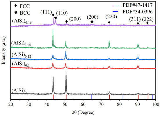
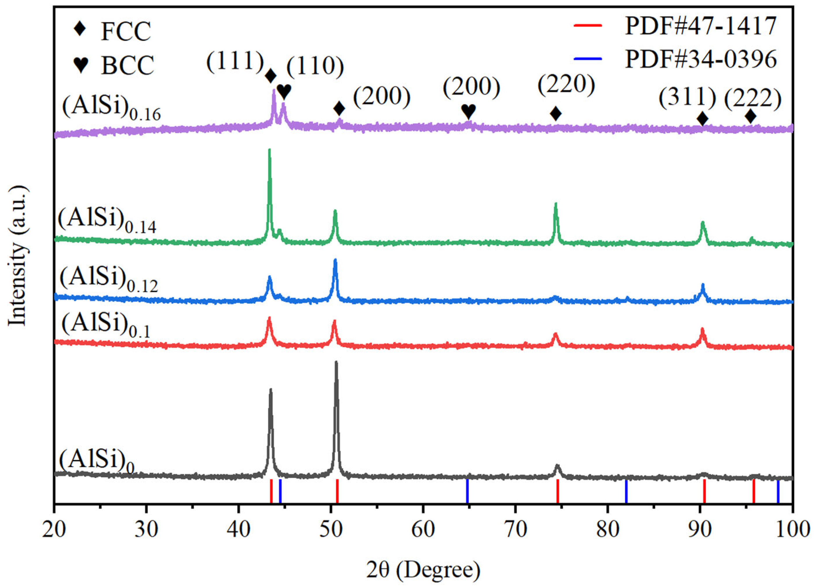
Figure 1 displays the XRD patterns of (AlSi)0, (AlSi)0.1, (AlSi)0.12, (AlSi)0.14, and (AlSi)0.16. From the XRD patterns, it can be evidently observed that with the co-addition of Al and Si, the intensity of the diffraction peaks changed and new diffraction peaks evolved. With the increase in the co-addition of Al and Si, the phase constitution changes from a single face-centered cubic (FCC) phase to an FCC+ body-centered cubic (BCC) dual-phase structure. Further analysis of the XRD patterns indicates that there are only diffraction peaks representing FCC phase in (AlSi)0, which demonstrate a single FCC crystal structure. While, with the co-addition of Al and Si to (AlSi)0.1, it was found that a characteristic diffraction peak of the BCC phase appeared at nearly 2θ of ~45°. Therefore, it is noticed that a mixture of FCC and BCC crystal structure forms in this series of alloys with the co-addition of Al and Si.
Figure 1.
XRD patterns of (AlSi)x (x = 0, 0.1, 0.12, 0.14, 0.16).
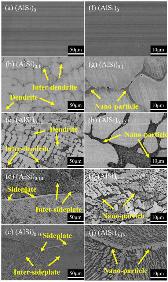
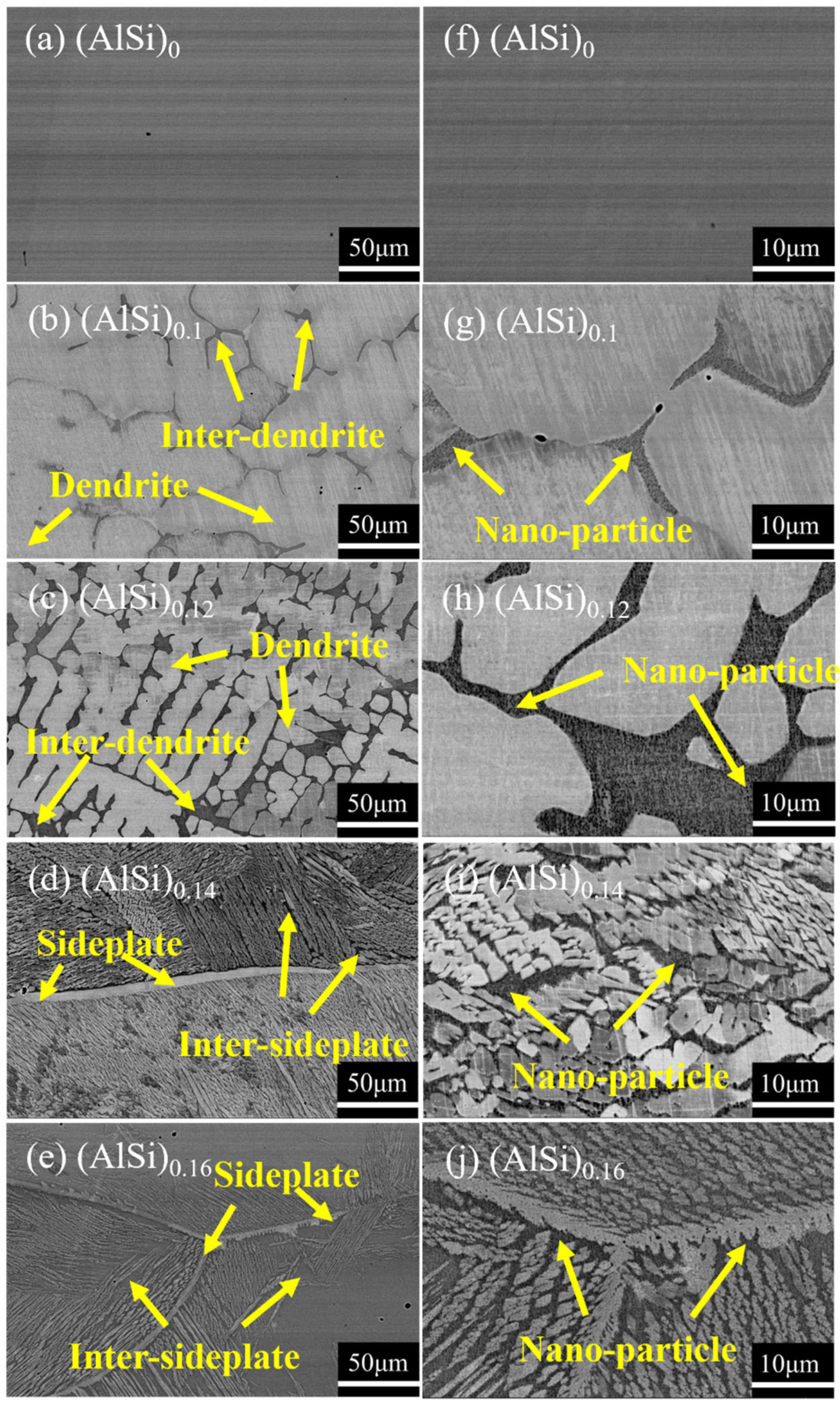
Figure 2 exhibits the back-scattered electron images of (AlSi)0, (AlSi)0.1, (AlSi)0.12, (AlSi)0.14, and (AlSi)0.16. As shown in Figure 2a,f, there was only homogeneous structures observed in the (AlSi)0. In Figure 2b,g, when Al and Si simultaneously increase, a typical dual-phase structure consisting of dendrite and inter-dendrite structures was clearly observed in (AlSi)0.1, and such structure has generally evolved from a liquid–solid phase transformation. With further co-addition of Al and Si to (AlSi)0.12, the dendrite structure is further refined. Interestingly, the dendrite structure of the alloy changed into a sideplate structure in (AlSi)0.14 with merely a slight increase in Al and Si, indicating a sharp change in the form of the microstructure, which has possibly resulted from solid-state phase transformation [29,30]. In addition, further refinement in sideplate structure is observed in (AlSi)0.16, and it could also be observed that some of the regions have no sideplates, indicating the inhibition of such microstructure. In addition, it was observed in Figure 2g–j that nano-particles were dispersed in the inter-dendrite/inter-sideplate regions in (AlSi)0.1, (AlSi)0.12, (AlSi)0.14 and (AlSi)0.16.
Figure 2.
SEM back-scattered electron images of (AlSi)0, (AlSi)0.1, (AlSi)0.12, (AlSi)0.14, and (AlSi)0.16.
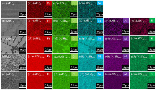
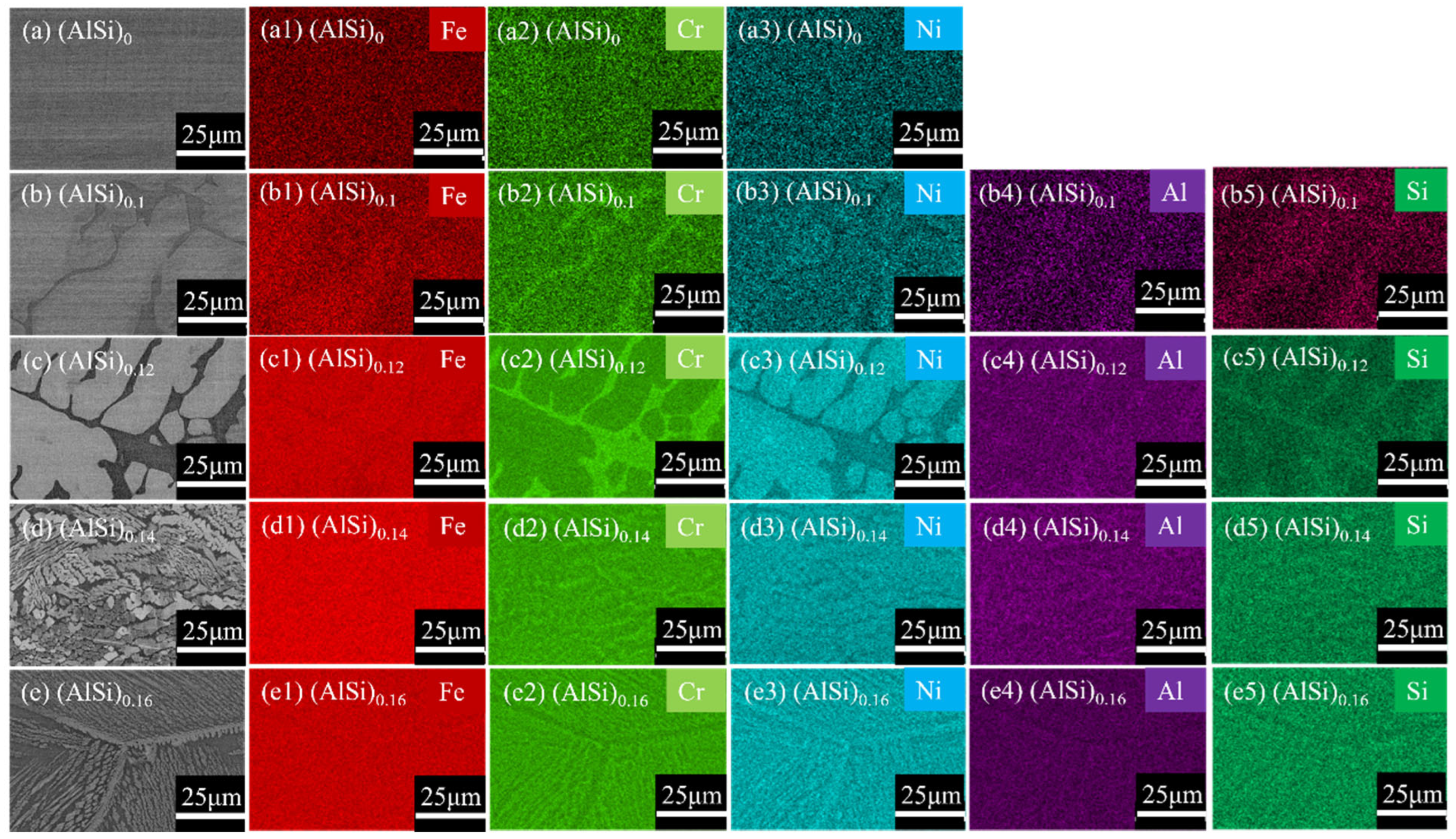
The EDS mapping results of constituent elements in (AlSi)0, (AlSi)0.1, (AlSi)0.12, (AlSi)0.14, and (AlSi)0.16 are exhibited in Figure 3. By observing Figure 3a(a1–a3), it is detected that all these elements were uniformly distributed in (AlSi)0 with a single-phase FCC structure. In Figure 3b–e, when Al and Si are simultaneously added in this series of as-cast HEAs, the segregation of elements is more prominent. Generally, Ni is greatly enriched within the dendrite/sideplate structure, while Cr is clearly enriched in the inter-dendrite/inter-sideplate structure. However, the difference in the distribution of the Fe, Si, and Al element between the dendrite/sideplate structure and the inter-dendrite/inter-sideplate structure is not significant, and it seems that Fe is more enriched in the dendrite/sideplate regions, while Al and Si are to some extent enriched in the inter-dendrite/inter-sideplate regions.
Figure 3.
EDS Element distribution patterns of (AlSi)0, (AlSi)0.1, (AlSi)0.12, (AlSi)0.14, and (AlSi)0.16.
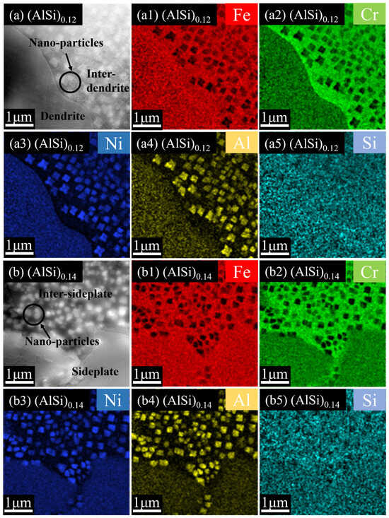
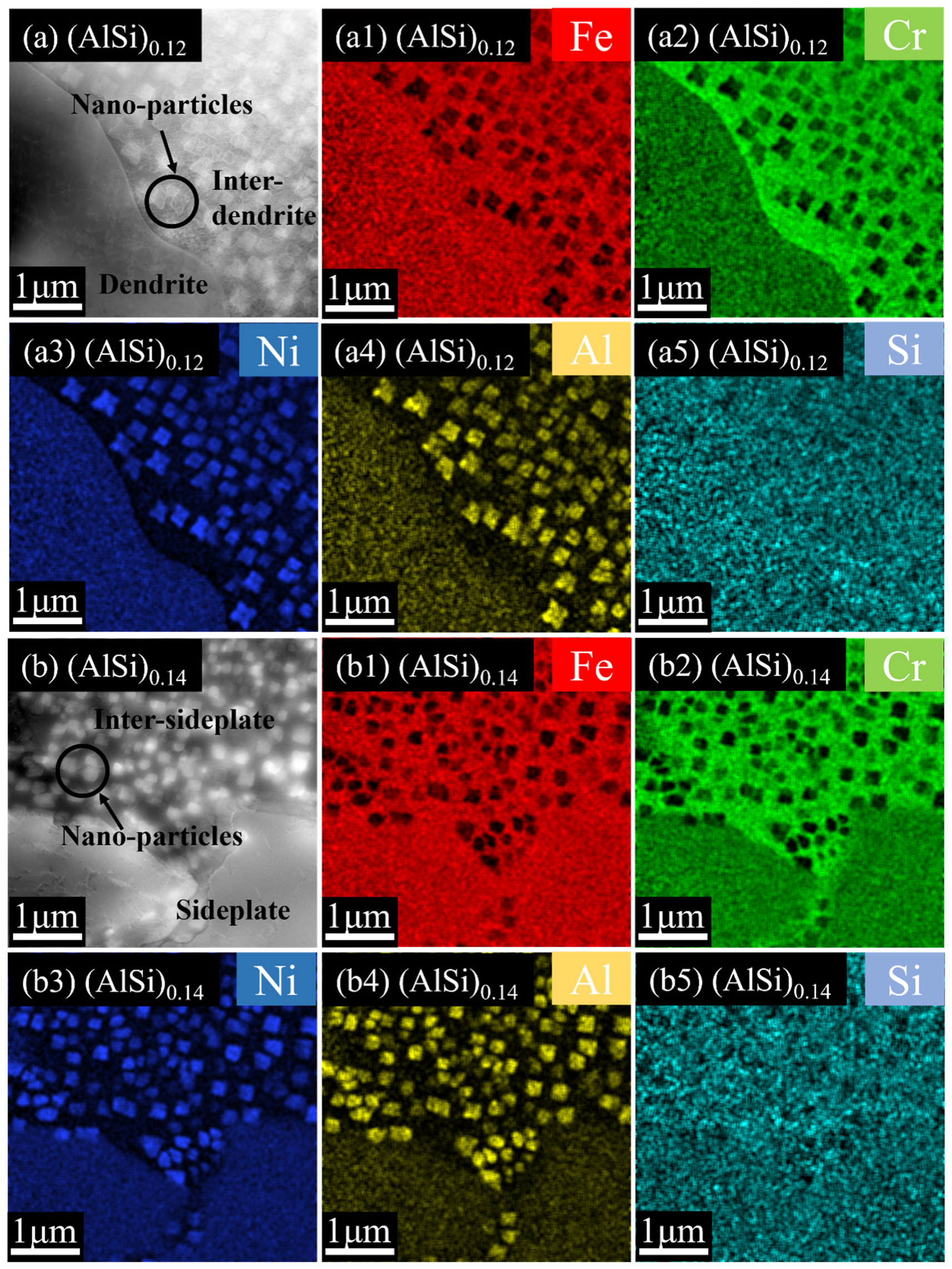
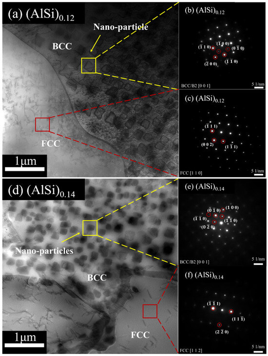
From the above results, it is found that there exists a drastic change in the microstructure at (AlSi)0.12 with a dendrite-type microstructure and (AlSi)0.14 with a sideplate-type microstructure. Therefore, these compositions are proper to be selected for further microstructure analysis. In order to further characterize the composition of the elements and the structure of the nano-particles in the (AlSi)0.12 and (AlSi)0.14 HEAs, the TEM was utilized, and it could be observed that in these specimens, a large number of nano-particles are located inside the inter-sideplate/inter-dendrite structure (Figure 4a,b). Further, as shown in Figure 4b, the nano-particles are located inside the inter-sideplate structure. In Figure 4(a1–a5) and Figure 4(b1–b5) that clearly show the element distribution of (AlSi)0.12, Ni is enriched in Fe, and Si elements are distributed in the dendrite/sideplate structure and the matrix of inter-dendrite/inter-sideplate structure, the Cr element is enriched in the matrix of inter-dendrite/inter-sideplate structure, while the Al element are enriched in the nano-particles.
Figure 4.
(a) HAADF-STEM images of (AlSi)0.12; (a1–a5) the elemental distribution maps corresponding to (a); (b) HAADF-STEM images of (AlSi)0.14; (b1–b5) the elemental distribution maps corresponding to (b).
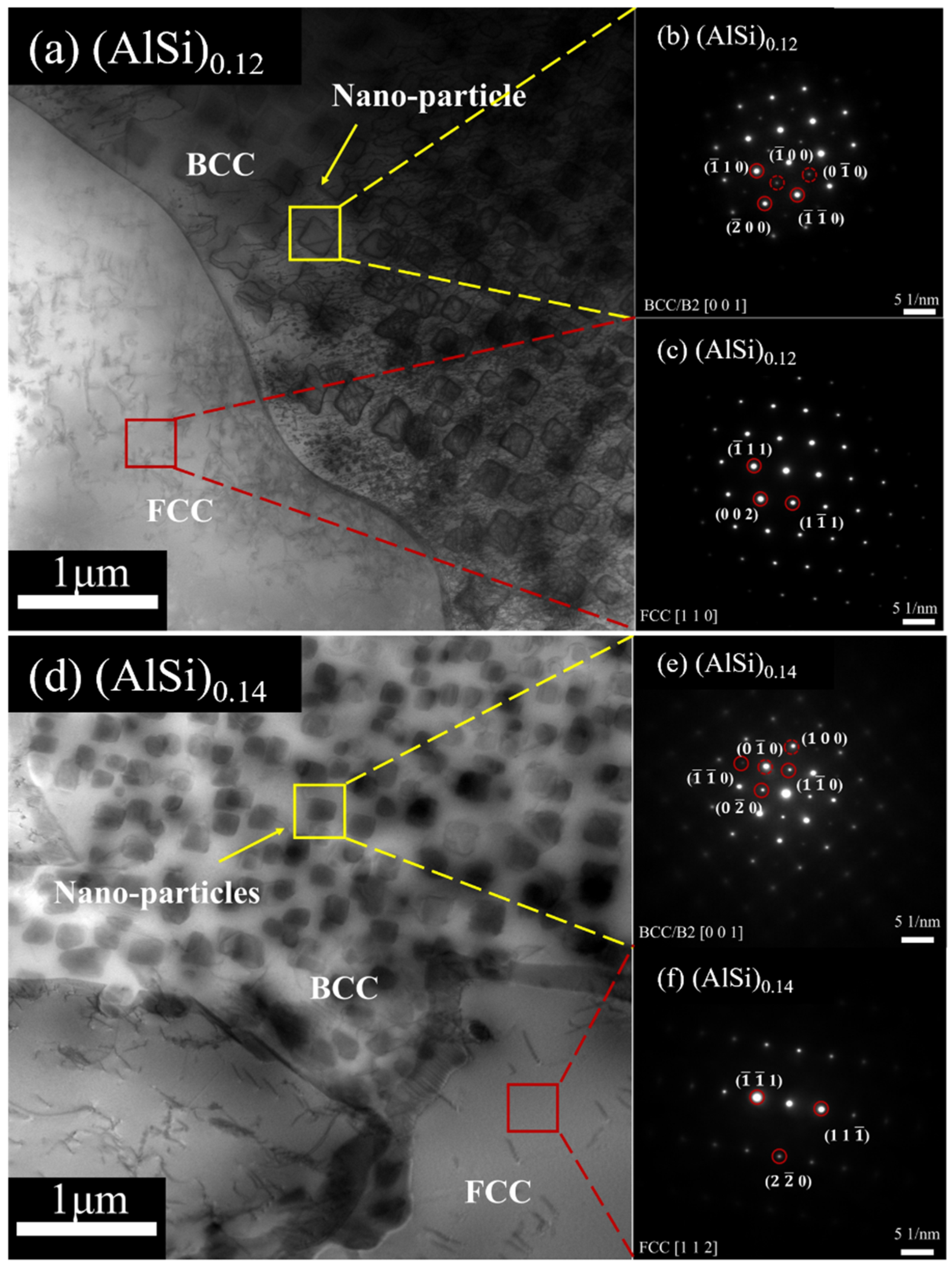
From the SAED patterns of selected regions of (AlSi)0.12 and (AlSi)0.14 displayed in Figure 5, the dendrite/sideplate structures in (AlSi)0.12 and (AlSi)0.14 (Figure 5a,d) exhibit the diffraction pattern corresponding to FCC phase (Figure 5b,e). Moreover, the inter-dendrite/inter-sideplate regions show the diffraction pattern according to BCC+B2 phase due to the existence of superlattice spots (Figure 5c,f), which is possibly caused by the precipitation of coherent (Ni, Al)-rich B2 nanoparticles in the BCC matrix.
Figure 5.
Bright-field images of (a) (AlSi)0.12 and (d) (AlSi)0.14; (b,c) and (e,f) the selected-area electron diffraction (SAED) patterns corresponding to the regions marked by yellow and red squares in (a,d).
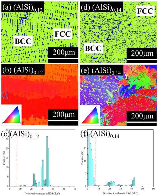
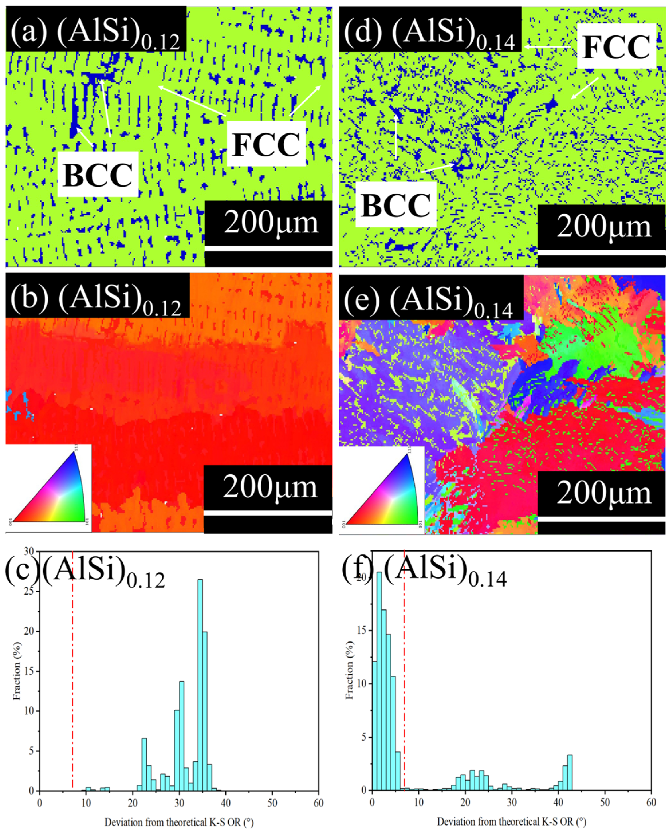
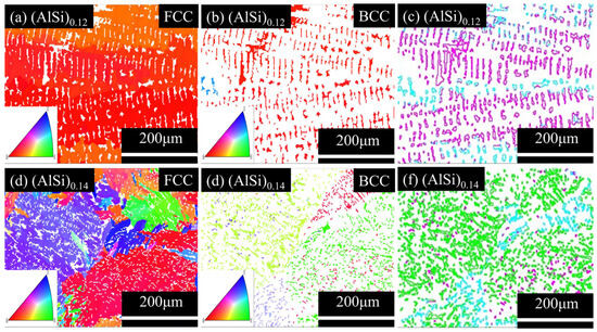
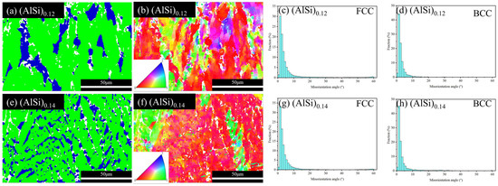
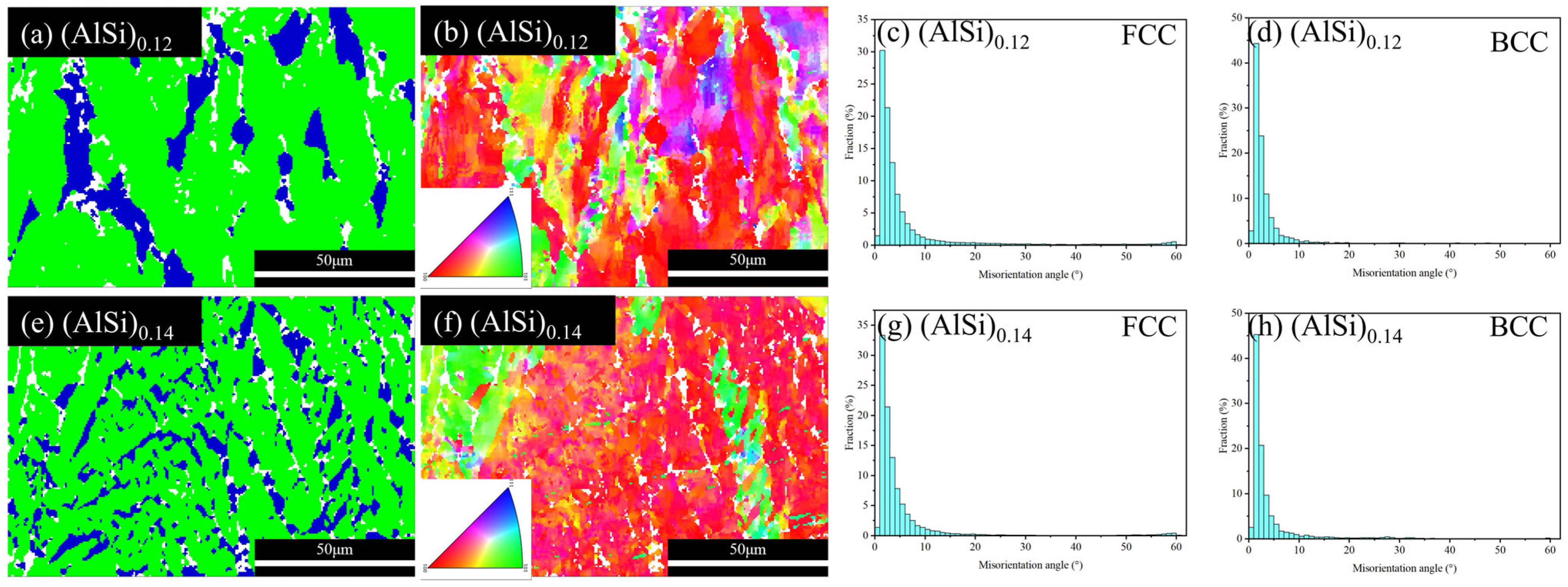
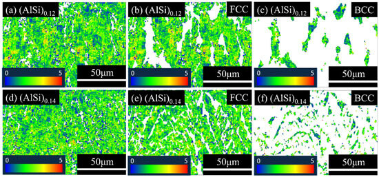
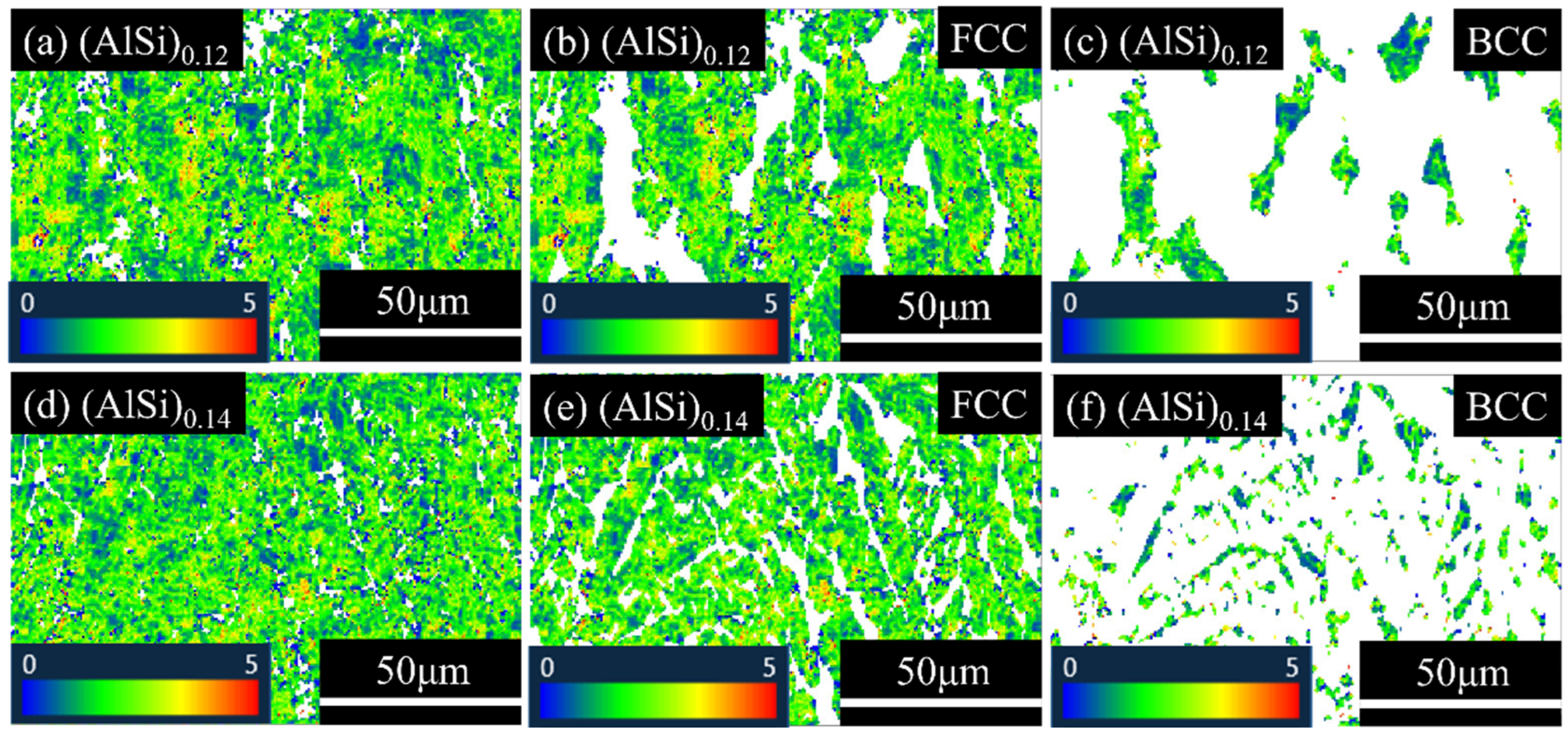
Figure 6 displays the phase maps, inverse pole figures (IPF), and the statistical results for the orientation distribution of adjacent FCC and BCC phases based on the Kurdjumov–Sachs (K-S) orientation relationship (OR) in (AlSi)0.12 and (AlSi)0.14. From Figure 6a,d, it is further confirmed that the dendrite/sideplate structures correspond to the FCC-type phase, while the inter-dendrite/inter-sideplate structures exhibit a good correspondence with the BCC-type phase. From Figure 6c,f, it could be found that in (AlSi)0.12, the orientation relationship of the FCC and BCC phases greatly deviate from theoretical K-S relation to a larger extent, while in (AlSi)0.14, such deviation is not prominent, and most of them are <7°.
Figure 6.
(a,d) the phase distribution maps of (AlSi)0.12 and (AlSi)0.14; (b,e) IPF images of (AlSi)0.12 and (AlSi)0.14; (c,f) the orientation distribution maps of adjacent FCC and BCC phases based on the K-S OR (the dotted line represented the angle of deviation from the theoretical K-S OR of 7°).
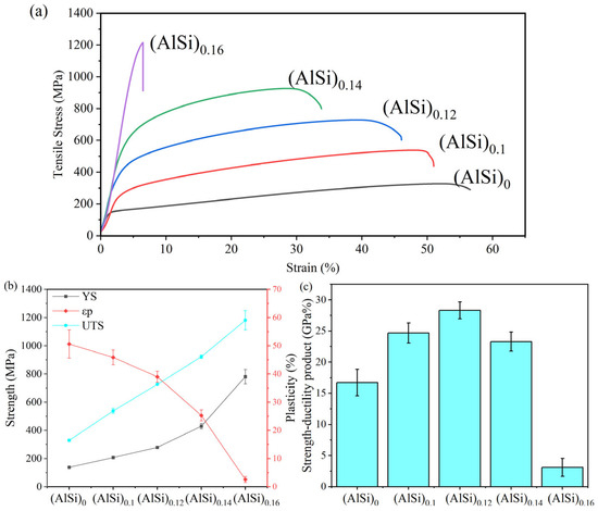
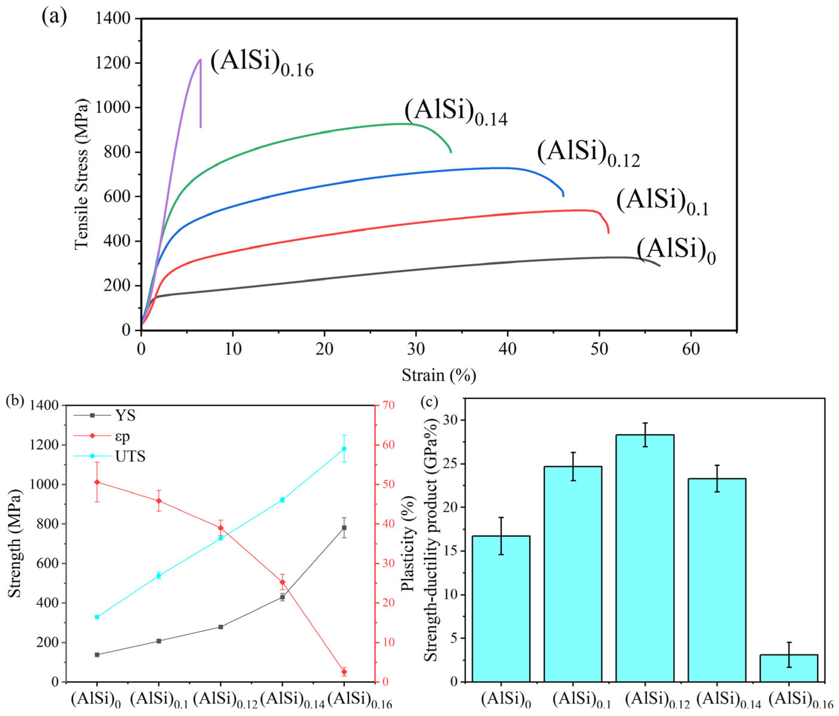
In order to obtain the mechanical properties of the alloys, tensile tests were carried out, and the results are shown in Figure 7. Figure 7a demonstrates the engineering tensile stress–strain curves of (AlSi)0, (AlSi)0.1, (AlSi)0.12, (AlSi)0.14, and (AlSi)0.16 at room temperature, while their mechanical properties are measured and summarized in Figure 7b,c. It is found that strength exhibits a progressive enhancement with the increase in the amount of Al and Si. The ultimate tensile strength (UTS) increases from 329.28 ± 8.74 MPa to 1181.0 ± 67.38 MPa, while the yield strength (YS) increases from 137.82 ± 3.11 MPa to 780.83 ± 50.94 MPa. However, their deformability gradually decreases along with the increase in strength, where the tensile plasticity (εp) decreases from 50.62 ± 5.03% to 2.58 ± 1.05%. In addition, in Figure 7c, the production of UTS and εp (UTS × εp) of the specimens shows a trend of increase at first with following decrease, and the optimal performance achieved at (AlSi)0.12. And, except (AlSi)0.12, it is also noticed that (AlSi)0.14 shows relatively high UTS × εp with very high strength among this series of as-cast HEAs, which is beneficial for further applications. In addition, it is noticed that (AlSi)0.14 exhibits high strength but significantly low plasticity, which is possibly caused by the weak division effect of the ductile FCC phase on brittle BCC phase, and the high connection of such a brittle structure would cause much lower deformability [31] compared to the other alloys in this work.
Figure 7.
Mechanical properties of (AlSi)0, (AlSi)0.1, (AlSi)0.12, (AlSi)0.14, and (AlSi)0.16: (a) engineering stress–strain curves; statistic results for (b) ultimate tensile strength, yield strength, and plasticity and (c) strength–ductility product.
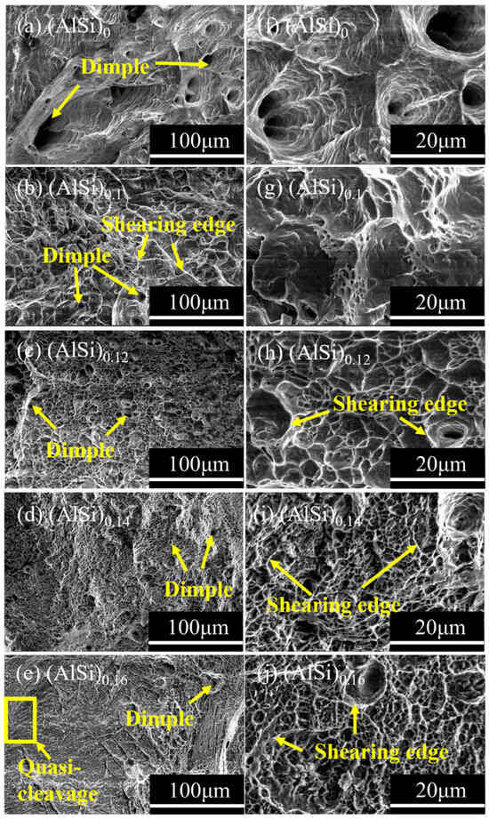
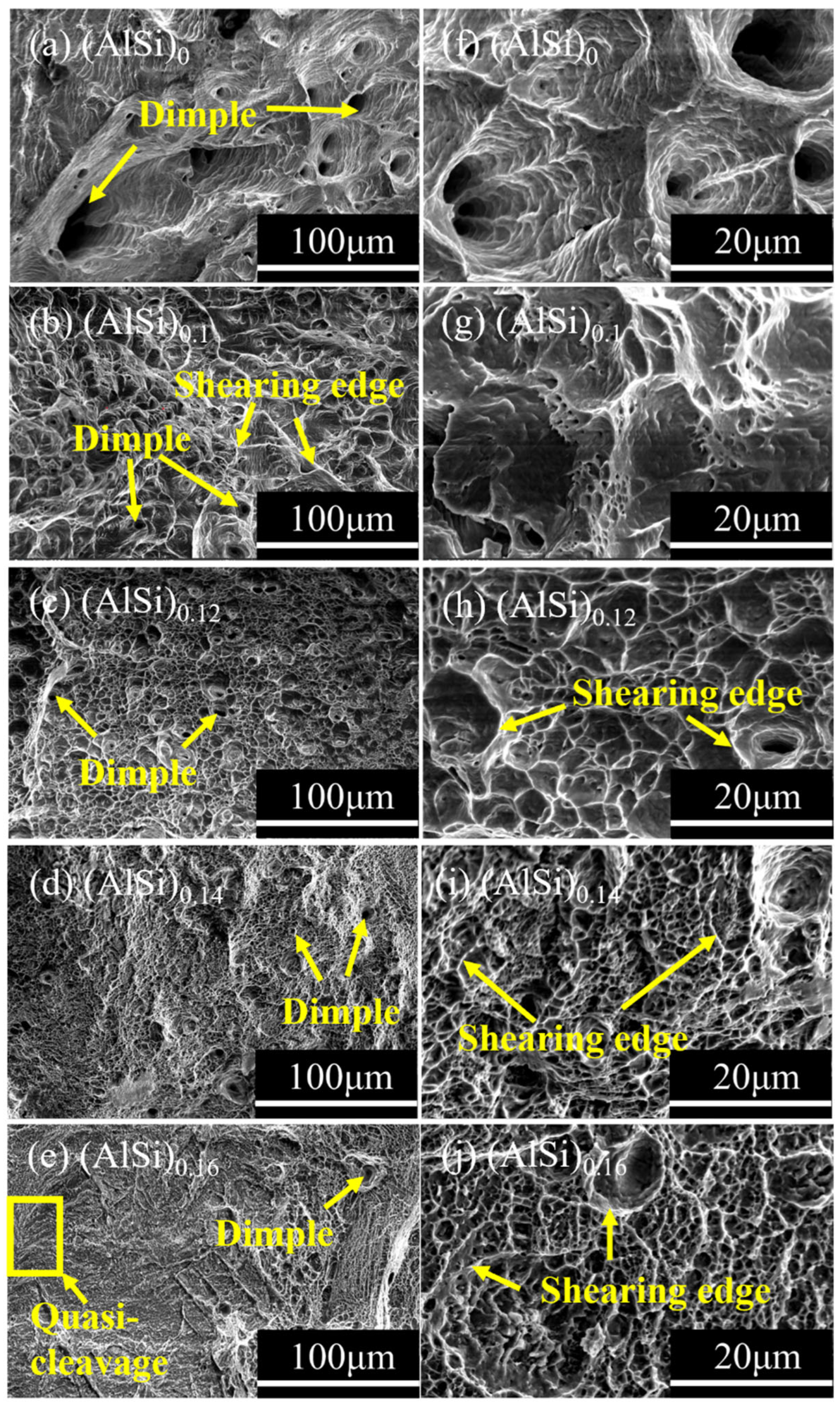
The fractured morphologies of (AlSi)0, (AlSi)0.1, (AlSi)0.12, (AlSi)0.14, and (AlSi)0.16 are shown in Figure 8. From Figure 8a,f, it could be observed that the fractured surface of (AlSi)0 was covered by a lot of dimples with larger sizes. With the co-addition of Al and Si, the fractured morphology changes significantly, where the dimples become finer, and on the other hand, the shearing edges could be found on the fracture surface, while the number of shearing edges increased with the co-addition of Al and Si. In addition, in Figure 8e,j, the cleavage pattern covers the fractured surface of (AlSi)0.16 with minor maintaining of shearing edges, as well as dimples in nano-scale. Meanwhile, it can be inferred that in the regions where the FCC phase was enriched, dimples are possible to form, and as the FCC phase show better plasticity and lower strength compared to BCC phase, and due to the difference in deformation capacity between the FCC phase and the BCC phase, the shearing edges formed at the phase boundaries, while the quasi-cleavage fracture pattern was formed in the region where the BCC-type phases are enriched.
Figure 8.
Fracture morphology after tensile deformation of (a,b) (AlSi)0, (c,d) (AlSi)0.1, (e,f) (AlSi)0.12, (g,h) (AlSi)0.14, and (i,j) (AlSi)0.16.
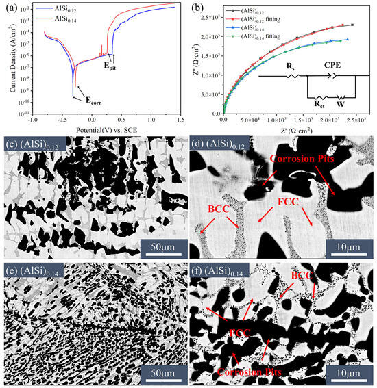
As mentioned above, (AlSi)0.12 and (AlSi)0.14 with high mechanical properties and similar composition, but significant diversity in typical microstructures, thus their corrosion resistance requires further investigation to evaluate their further application in complex and harsh environments. Figure 9a exhibits the potentiodynamic–polarization curves of (AlSi)0.12 and (AlSi)0.14 in 3.5 wt.% NaCl solution. As they have passivation behaviors, pitting potential (Epit) and the width of passive region (ΔEp) are proper to evaluate their corrosion resistance. It is measured that the Epit and ΔEp of (AlSi)0.12 (0.341 V and 0.663 V) are higher than those of (AlSi)0.14 (0.257 V and 0.535 V), and such results are both comparable to typical (such as 304 and 316L) stainless steels [7,32,33]. As higher Epit and ΔEp usually represent that the alloy is more resistant to pitting corrosion, the result indicates that (AlSi)0.12 shows higher corrosion resistance than (AlSi)0.14, which is possibly caused by more stable passive film that slows down the corrosion and requires further clarification. Figure 9b displays the Nyquist plots of (AlSi)0.12 and (AlSi)0.14 in 3.5% NaCl solution, and it could be detected that the radius of capacitive arc corresponding to the protectiveness of passive film for (AlSi)0.12 is larger than that of (AlSi)0.14. Generally, the larger radius of capacitive arc implied that there was a higher charge transfer resistance (Rct) on the surface of the alloys, which leads to a decrease in the rate of electrochemical reaction, and could reflect the level of corrosion resistance to a certain extent [34]. In order to further investigate the corrosion behavior of (AlSi)0.12 and (AlSi)0.14, back-scattered electron images of the corroded morphologies after potentiodynamic–polarization tests in 3.5 wt.% NaCl solution were observed. The detailed results for electrochemical tests are summarized in Table 1. As displayed in Figure 9c,e, in (AlSi)0.12 and (AlSi)0.14, the corrosion appears mainly inside the FCC phase and most of it stopped at the phase boundaries, forming dispersed and large corrosion pits. In addition, it is found from Figure 9d,f, multiple nano-particles inside the BCC phase are also prior to corrosion.
Figure 9.
(a) Potentiodynamic–polarization curves of (AlSi)0.12 and (AlSi)0.14 in 3.5 wt.% NaCl solution at 298 K; (b) nyquist plots of (AlSi)0.12 and (AlSi)0.14 (the inset is the equivalent circuit for fitting the data, Rs: solution resistance; CPE: constant phase element; Rct: charge-transfer resistance; W: Warburg impedance); (c–f) backscattered electron images for typical corroded morphology of (AlSi)0.12 and (AlSi)0.14.
Table 1.
Electrochemical parameters of (AlSi)0.12 and (AlSi)0.14.
4. Discussion
From the results shown above, proper co-addition of Al and Si could effectively enhance strength with high plasticity, as well as realizing high corrosion resistance simultaneously in as-cast Fe-rich Fe-Cr-Ni-based HEAs, which is beneficial for further application of this series of low-cost high-performance materials. However, as for better understanding the corresponding mechanisms, further in-depth analysis according to phase formation, deformation, and corrosion behaviors is urgently required. Therefore, the following discussion is based on these aspects mentioned above:
4.1. Effect of the Co-Addition of Al and Si on Phase Formation
From the XRD patterns, SEM images and EBSD results shown above, it could be concluded that the co-addition of Al and Si is beneficial to promote the FCC→FCC+BCC phase transformation. Guo et al. systematically investigated the relationship between valence electron concentration (VEC) and the stability of FCC and BCC solid solution. The FCC phase was stable at high VEC values (≥8), while the mixed BCC and FCC phases tend to form at VEC values between 6.87 and 8, while the BCC phase was stable at low VEC values (<6.87) [35]. The VEC values of HEAs can be obtained using the following equation [36]:
where ci is the atomic percentage of an element, while (VEC)i is the valence electron concentration of that element. The VEC values of Fe, Cr, Ni, Al and Si are 8, 6, 10, 3, and 4, respectively [37]. By calculation, Table 2 shows the VEC of the studied as-cast HEAs. For the (AlSi)0 alloy, the VEC value was 8.00 which should form the FCC phase. With the co-addition of Al and Si, the VEC decreased from 7.63 to 7.43, allowing the coexistence of the FCC phase and the BCC phase in the alloys, which is in agreement with the XRD results.
Table 2.
VEC of (AlSi)0, (AlSi)0.1, (AlSi)0.12, (AlSi)0.14, and (AlSi)0.16.
Some studies had indicated that in Fe-Cr-Ni HEAs, the addition of Al could induce strong lattice distortion [38,39]. In order to reduce the energy of lattice distortion, the FCC phase tends to transform into the BCC phase, which promotes the FCC→BCC phase transformation. In terms of results, the effect of Al addition was similar to that of co-addition of Al and Si. In addition, the alloying of Si in Fe-Cr-Ni-based HEAs would generally not cause the FCC→BCC phase transformation, but leads to the formation of a Si-rich compound phase. However, the co-addition of Al and Si could influence the distribution of Si into BCC phase to avoid brittle Si-rich phase formation, which is also beneficial for modulation of the properties of different phases in this series of as-cast HEAs, which may further influence their mechanical properties and corrosion resistance.
In order to better understand the co-addition of Al and Si on the phase evolution in these as-cast HEAs with different kinds of microstructures, i.e., dendrites-type/sideplate-type, the IPF images for FCC and BCC phases in (AlSi)0.12 and (AlSi)0.14 are placed separately, and the results are shown in Figure 10a–d. In Figure 10a,b, the FCC and BCC phases in (AlSi)0.12 show similar orientation in the dendrites and inter-dendrite regions, respectively. However, in Figure 10d,e, the cellular regions with the same orientation for BCC phases could be observed in (AlSi)0.14, while the FCC phase could be regarded as distribution in such cellular regions, and the difference in the orientation of the FCC phase inside the same cellular region seems quite large. From Figure 10c,f, it demonstrates that the orientation relationships of the FCC and BCC phases deviated considerably from the K-S OR in (AlSi)0.12, whereas most of the deviations in the (AlSi)0.14 alloy are smaller than 7°. Combined with the SEM images of these as-cast HEAs, it was deduced that the FCC phase was formed during the liquid-solid transformation process in (AlSi)0.12, while in combination with the sideplate-type FCC phase in the (AlSi)0.14 alloy and the small deviation between orientation relationship of the two phases and the theoretical K-S OR, the microstructure in this as-cast HEA is possible to form via solid-state phase transformation during the cooling process after solidification, which causes the result that the FCC phase forms in the BCC parent phase. In sum, with the co-addition of Al and Si, the phase formation mechanism of the alloys could change, and the formation of the FCC phase transformed from the liquid–solid route to the solid-state route.
Figure 10.
IPF images of (a) FCC phase and (b) BCC phase, and (c) distribution of phase boundaries for (AlSi)0.12; IPF images of (d) FCC phase and (e) BCC phase, and (f) distribution of phase boundaries for (AlSi)0.14 (as in (c,f), different colors of the phase boundaries represented the deviation of the orientation relationship of the two adjacent phases from the theoretical K-S relationship: 0°~7° (green); 7°~30° (blue); >30° (pink)).
4.2. Effect of the Co-Addition of Al and Si on Mechanical Properties
Furthermore, in terms of mechanical properties, according to Figure 7, the co-addition of Al and Si could significantly improve the strength of the alloys. In order to investigate the origin of the high mechanical properties of this series of as-cast HEAs, (AlSi)0.12 and (AlSi)0.14, which have relatively higher comprehensive properties and typical microstructures, were selected and their EBSD results after fracture including phase maps, IPF images, the statistical orientation angles of the adjacent FCC/BCC phases are shown in Figure 11. Generally, there are several possibilities in considering the modification of mechanical properties in HEAs, namely, transformation-induced plasticity (TRIP) effect [4,40], twinning-induced plasticity (TWIP) effect [5,41], as well as the high mechanical properties by the nature of phases in the alloys. It is known that, if metastable phase transform to the new phase during deformation, it is beneficial for accommodating plastic strain and delays necking, then enhancing mechanical properties. However, measured from Figure 11a–d, the proportions of FCC and BCC phases in (AlSi)0.12 and (AlSi)0.14 after fracture are very close to the proportions before tensile test, indicating that there exists no obvious phase transformation during the tensile process, thus it could be deduced that there is no prominent TRIP effect on these alloys. Meanwhile, mechanical twinning formed during deformation would increase strain hardening by generating new interfaces that impede dislocation motion, which is also important in realizing high mechanical properties. Nevertheless, by observing Figure 11b–d,f–h, it was found that most of the difference in grain boundary orientation between the neighboring FCC/BCC phase is less than 15° in both (AlSi)0.12 and (AlSi)0.14, and no obvious twin boundaries form in these HEAs during deformation, which also indicates that the TWIP effects are not prominent in (AlSi)0.12 and (AlSi)0.14. Therefore, the plasticity of the alloys could be regarded as a reflection of their own deformation capacity, and the refinement of FCC and BCC phases caused by solid-state phase transformation is beneficial for increasing strength in (AlSi)0.14, while the high plasticity is generally caused by the coarse structure in (AlSi)0.12.
Figure 11.
(a,e) the phase maps of (AlSi)0.12 and (AlSi)0.14 after tensile tests; (b,f) the IPF of (AlSi)0.12 and (AlSi)0.14 after tensile tests; (c,g) the statistical plots of grain boundary orientation angle of FCC phase in (AlSi)0.12 and (AlSi)0.14 after tensile tests; (d,h) the statistical plots of grain boundary orientation angle of BCC phase in (AlSi)0.12 and (AlSi)0.14 after tensile tests.
It is known that the HEAs containing both FCC and BCC phases generally show a heterostructure effect due to the significant diversity in mechanical properties of these two phases [42], and such effect could be observed by evaluating the change in the kernal average misorientation (KAM) in different phases before and after tensile deformation [43]. The KAM can be used to evaluate the diversity for the density of geometrically necessary dislocations (GNDs) in alloys, which can be calculated by the following equation [44]:
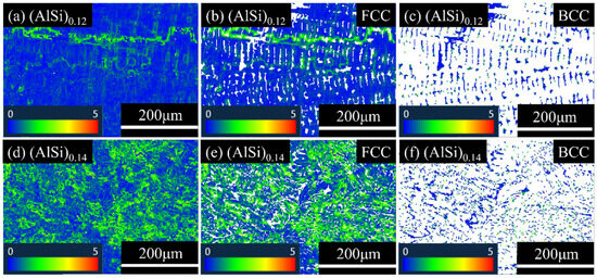
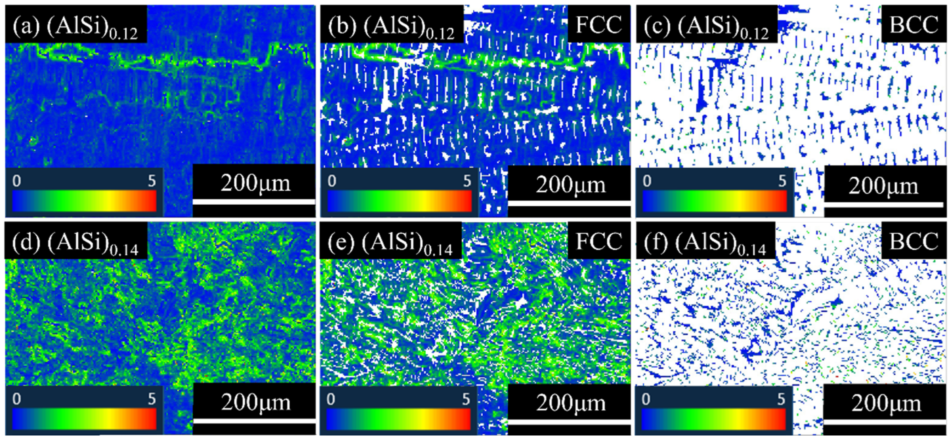
where ρGND is the GND density of a point, θ is the localized orientation difference angle measured by EBSD, b is the Burgers vector, and μ is the step size during the EBSD test. As KAM increases, the density of dislocations would also increase. Figure 12 exhibits the KAM maps of (AlSi)0.12 and (AlSi)0.14, as well as the ones for their FCC and BCC phases in the as-cast state, while the average KAM values are summarized in Table 3. It is revealed that the average KAM value of the FCC phase in (AlSi)0.12 alloy (0.4°) is larger than the BCC phase (0.25°). In addition, the KAM values at the interfaces of the dendrite regions are significantly higher than the other regions. Meanwhile, the average KAM values of both FCC and BCC phases in (AlSi)0.14 increase, that is, the FCC phase rises to 1.18° and the BCC phase increases to 0.43°.
Figure 12.
Overall KAM plots of (a) (AlSi)0.12 and (d) (AlSi)0.14; individually extracted KAM plots of the FCC phases in (b) (AlSi)0.12 and (e) (AlSi)0.14; individually extracted KAM plots of the BCC phases in (c) (AlSi)0.12 and (f) (AlSi)0.14.
Table 3.
Average KAM values of individual phases in (AlSi)0.12 and (AlSi)0.14.
Figure 13 shows the KAM maps of (AlSi)0.12 and (AlSi)0.14, as well as the ones for their FCC and BCC phases in a fractured state, while the average KAM values are also summarized in Table 3. Compared to the specimens before tensile deformation, the KAM values of the ones after fracture becomes significantly larger. And, more interestingly, the KAM values in the BCC phase enhance remarkably. As it is generally regarded as a brittle phase, such phenomenon could be contributed by the heterostructure effect, and both enhancement in dislocation density for FCC and BCC phase could also explain the high plasticity of both as-cast HEAs.
Figure 13.
Overall KAM plots of (a) (AlSi)0.12 and (d) (AlSi)0.14 after tensile tests; individually extracted KAM plots of the FCC phases of (b) (AlSi)0.12 and (e) (AlSi)0.14 after tensile tests; individually extracted KAM plots of the BCC phases of (c) (AlSi)0.12 and (f) (AlSi)0.14 after tensile tests.
In combination with the back-scattered electron images shown in Figure 2, it was observed that the structures of the alloys turn finer with the increasing co-addition of Al and Si, and the refinement of the structures could lead to a remarkable increase in the amount grain/phase boundaries. When the dislocations move inside the grains, they are not able to move across such boundaries easily to other grains, and eventually form the pile-up of dislocation, which leads to the improvement of strength. In addition, the Hall–Petch equation can also illustrate the link between grain refinement and the strength of alloys [45]:
where σy represents the YS of the alloy, σ0 is the lattice friction of that alloy, d is the average grain size, while ks is the Hall–Petch strengthening factor. From this principle, it is clear that the strength of the alloy became higher as the grain size is refined. Moreover, as mentioned above, the FCC phase is quite different from the BCC phase in HEAs considering their mechanical properties [46], so during tensile deformation, the two different phase structures would induce inhomogeneous deformation because of mechanical heterogeneity. This inhomogeneous deformation could also be reflected from the formation of shearing edges on the fractured surfaces. When the alloy was stretched, the grains located on both sides of the phase boundary would cause inhomogeneous deformation due to the difference in plasticity, and then the phase with poor plasticity would fracture first, which eventually forms a shearing edge [47]. In order to coordinate the deformation between different phases on both sides of the boundary, geometrically necessary dislocations (GNDs) would form the pile-up of dislocation inside the grain with better plasticity and inhibited its deformation, which then led to hetero-deformation-induced (HDI) strengthening [48]. As analyzed above, the strengthening effect of the co-addition Al and Si on Fe-Cr-Ni based as-cast HEAs is not a result of a single strengthening mechanism, but rather a result of the synergy effect of multiple strengthening mechanisms.
4.3. Effect of Co-Addition of Al and Si on Corrosion Resistance
As deduced from Figure 9, although both (AlSi)0.12 and (AlSi)0.14 exhibit excellent corrosion resistance, the former one shows slightly higher Epit and a wider passivation region compared to the latter one. In order to further understand the mechanism for such a phenomenon about the diversity in corrosion resistance, the passive films of (AlSi)0.12 and (AlSi)0.12, as well as surface potential diversity between the different phases in these as-cast HEAs, were studied.
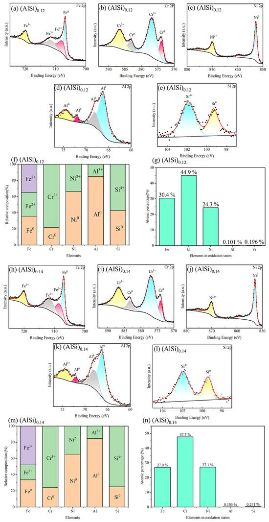
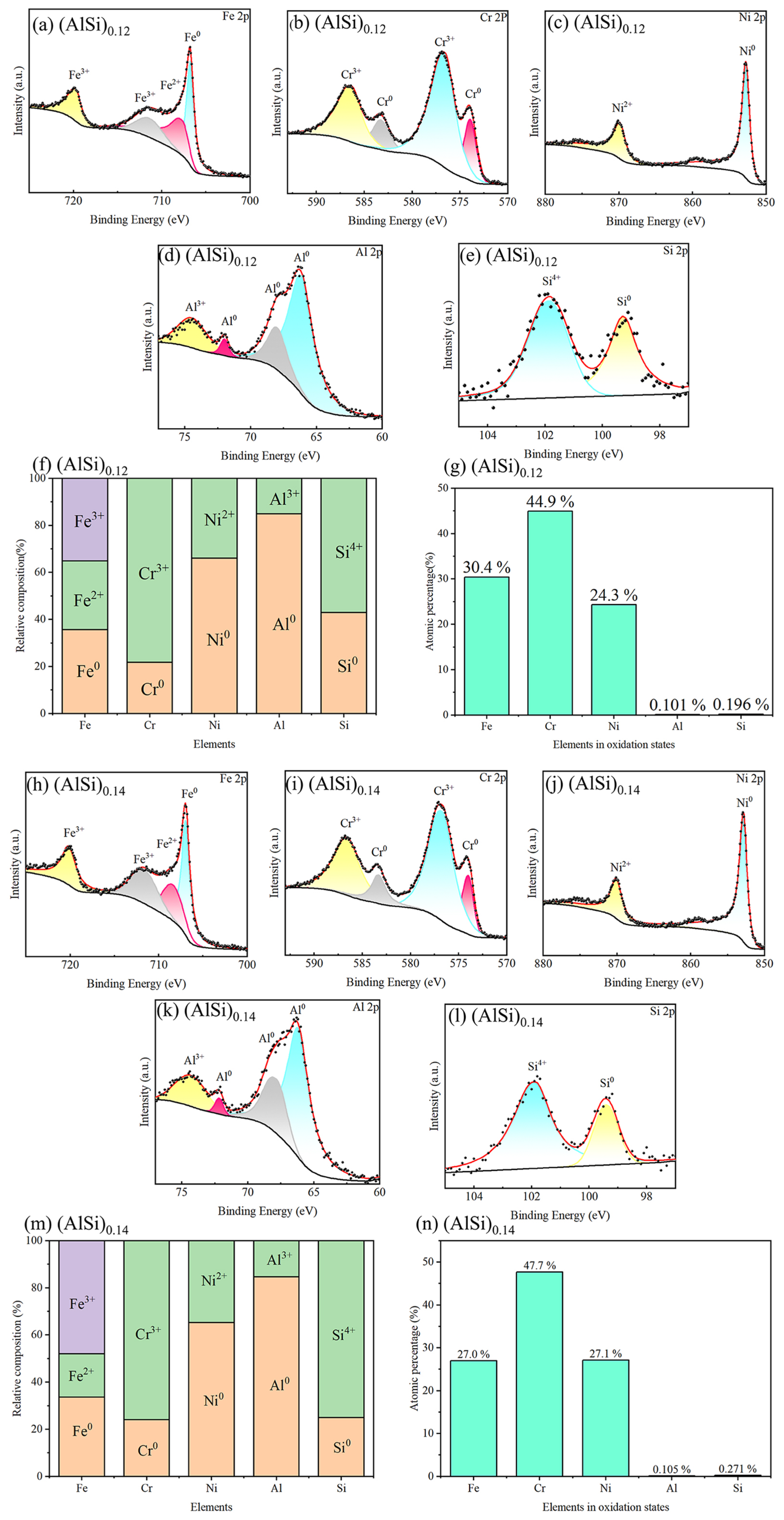
In general, the addition of the Cr element can improve the corrosion resistance of alloys because Cr can form a dense and stable Cr2O3 passive film during the corrosion process yet significantly reduce the corrosion rate [49]. Although there exists a large number of Cr in (AlSi)0.12 and (AlSi)0.14 alloys, the high corrosion resistance of the alloys may not be simply attributed to the high content of Cr in the alloys, but other elements such as Al and Si are also reported to play an important role in the formation of passive film. In order to clarify the element effect on the passivation behavior these as-cast HEAs containing different amounts of Al and Si elements, the composition of the surface passive films of (AlSi)0.12 and (AlSi)0.14 were investigated by XPS. Figure 14 shows the XPS spectra of the passive films of (AlSi)0.12 and (AlSi)0.14 formed after immersing in a 3.5% NaCl solution for 168 h, and also lists the statistical results of the percentage of elements with different valence states on the surface of the passivation films. From Figure 14a–j, it could be observed that the surface of passive films of both (AlSi)0.12 and (AlSi)0.14 contain elements of different valence states including Fe0, Cr0, Ni0, Al0, Si0, Fe2+, Fe3+, Cr3+, Ni2+, Al3+, and Si4+. In addition, the percentage of elements in different valence states on the surface of the passive films of the alloys in Figure 14l,n is calculated by the equation:
where CM is the percentage of a specific valence element in the passivation film, IM is a corresponding peak intensity for the area of each valence element, and SM is the sensitivity factor for that element. And the sensitivity factors for the elements Fe, Cr, Ni, Al, and Si are given in Table 4. In Figure 14l, it was identified that in the passive films of both two alloys the contents of Cr3+ and Ni2+ are much high while Al3+ and Si4+ are significantly low, which implied that Cr3+ and Ni2+ play a major role in the process of passive film formation, while Al3+ and Si4+ show less influence on its formation. Moreover, from the analysis of Figure 14k,m, it is found that with the co-addition of Al and Si, no obvious change in passive film composition could be observed, which indicated that the content of Al and Si may not the main reason for the significant changes in the corrosion resistance, and their protect ability of the passive films on these as-cast HEAs are similar, and the diversity in corrosion resistance especially Epit may be caused by other reasons.
Figure 14.
XPS spectra for (a) Fe, (b) Cr, (c) Ni, (d) Al, (e) Si; (f) the percentage of certain elements with different values and (g) the proportion of different elements in the oxidation state on the surface of (AlSi)0.12; XPS spectra for (h) Fe, (i) Cr, (j) Ni, (k) Al, (l) Si; (m) the percentage of certain elements with different values and (n) the proportion of different elements in the oxidation state on the surface of (AlSi)0.14.
Table 4.
Sensitivity factors of alloying elements.
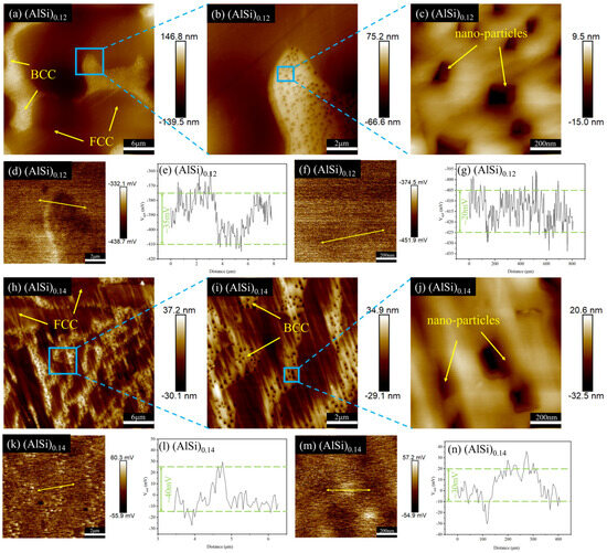
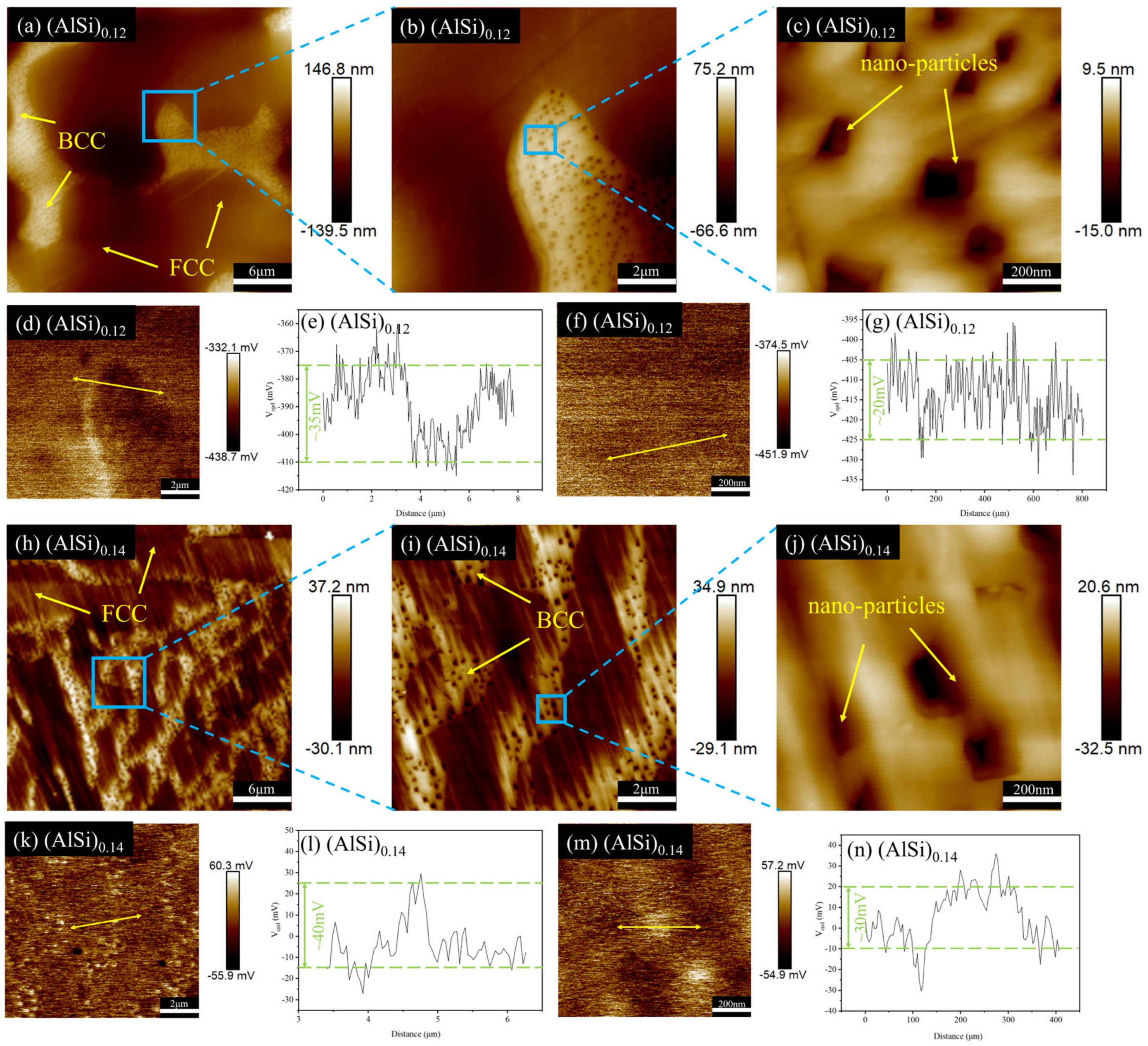
As indicated in Figure 1, when the co-addition of Al and Si to (AlSi)0.1, the microstructure of the alloys changed from the FCC structure to the FCC + BCC structure. There were different chemical properties for different phase structures due to their distinct crystal structures and compositions, which may have led to the formation of micro-galvanic cells between different phases and accelerated the corrosion. Figure 15 illustrates the surface morphologies, kelvin probe force microscopy (KPFM) images, and distributions of contact potential difference (VCPD) for (AlSi)0.12 and (AlSi)0.14. As can be obtained from Figure 15e,g, the VCPD between the FCC phase and BCC phase in (AlSi)0.12 is about 35 mV, and that between the BCC phase and nano-particles is about 20 mV. Furthermore, as shown in Figure 15l,n, in (AlSi)0.14, it was observed that the VCPD between the FCC phase and the BCC phase was close to that of (AlSi)0.12, as well as the one between the BCC phase and the nano-particles. This indicates that the (AlSi)0.12 and (AlSi)0.14 have a tendency to undergo selective corrosion, but such a trend is not so significant, leading to excellent corrosion resistance. In addition, lattice distortion, dislocations, and other defects are easy to form at the phase interface, resulting in higher energy and increased chemical activity at the interface, which results in being more susceptible to corrosion [32,50]. Thus, when the alloy shows a multi-phase structure, it is necessary to consider the influence of the size for the microstructure and the phase interface on the corrosion resistance of the alloys. Combined with Figure 2, the microstructure of the alloys underwent significant refinement as the increase in co-addition of Al and Si, and the (AlSi)0.14 alloy had finer FCC and BCC phase structures and the area of the phase interface between the FCC and BCC phases increased. The finer FCC and BCC phases would result in an increase in the number of micro-galvanic cells that may form between the two phases, thereby accelerating the corrosion process. According to the statistical results of the KAM values for the FCC and BCC phases in the (AlSi)0.12 and (AlSi)0.14 alloys, the average KAM values of both the FCC and BCC phases increased in the latter one, indicating a significant increase in dislocation density within the alloy. Moreover, the higher density of dislocations would induce greater lattice distortion, generating higher distortion energy, which in turn created more electrochemical active sites and increased the corrosion rate.
Figure 15.
(a–c) Surface morphology of (AlSi)0.12 taken from AFM; (d) KPFM image of (b,e) the distribution of VCPD in the line mark by double-headed arrow in (d); (f) KPFM image of (c,g) the distribution of VCPD in the line mark by double-headed arrow in (f); (h–j) surface morphology of (AlSi)0.14 taken from AFM; (k) KPFM image of (i,l) the distribution of VCPD in the line mark by double-headed arrow in (k); (m) KPFM image of (j,n) the distribution of VCPD in the line mark by double-headed arrow in (m).
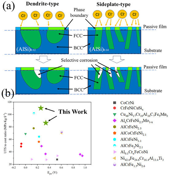
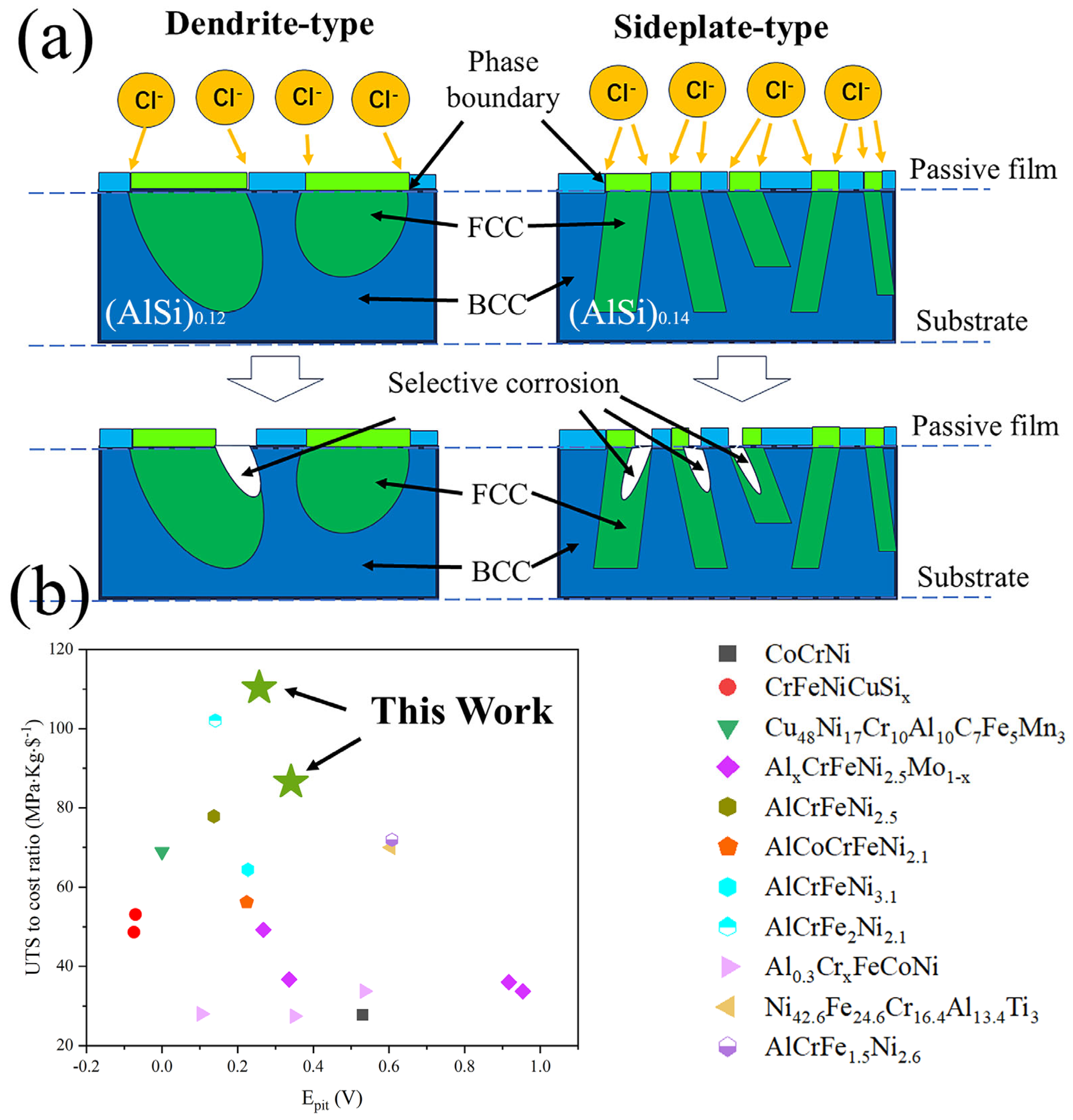
In summary, the effect of the co-addition of Al and Si on the corrosion resistance of Fe-rich Co-free Fe-Cr-Ni based HEAs was complex, and the schematic diagram for such a possible mechanism is shown in Figure 16a. The refinement of microstructure and the promotion of the FCC-to-BCC phase transformation by the co-addition of Al and Si would lead to the increase in the interfacial area and dislocation density within the alloys, which results in a reduction in corrosion resistance. However, it also facilitated the formation of (Cr3+, Ni2+)-rich passive films. Nevertheless, these effects were less dominant compared to the influence of Cr and Ni content, ultimately resulting in similar corrosion resistance for the (AlSi)0.12 and (AlSi)0.14, and (AlSi)0.12 exhibits slightly better corrosion resistance compared to the (AlSi)0.14. In addition, Figure 16b shows the statistical results comparing corrosion resistance, mechanical properties, and cost of (AlSi)0.12 and (AlSi)0.14 with other typical as-cast HEAs [51,52,53,54,55,56,57,58] considering the UTS-to-cost ratio and Epit. The result shows that it could realize high mechanical properties under low cost, while possessing good corrosion resistance. Through the mechanisms discussed above, it is promising to further optimize the comprehensive properties of this series of high-performance as-cast HEAs, which is beneficial for their future development.
Figure 16.
(a) Schematic diagram for corrosion mechanism of (AlSi)0.12 and (AlSi)0.14 in 3.5 wt.% NaCl solution; (b) comparison of these two alloys with typical as-cast HEAs, Adapted from Refs. [51,52,53,54,55,56,57,58] considering Epit and UTS-to-cost ratio.
5. Conclusions
In summary, this study systematically investigated the effects of the co-addition of Al and Si on the microstructure, mechanical properties, and corrosion resistance of a series of Fe-rich Co-free Fe-Cr-Ni based HEAs. The findings could be summarized as follows:
- (1)
- The effects of co-addition of Al and Si on the phase structure of this series of as-cast HEAs is similar to that of single addition of Al in (Fe-Cr-Ni)-containing HEA systems. With the increasing addition amount, the structure of HEA is transformed from FCC phase to FCC+BCC dual-phase structure. And at certain narrow region for the concentration of Al and Si, the shape of FCC phase suddenly change from coarse dendrite-type to fine sideplate-type, which is possibly caused by the evolution from liquid–solid transformation to solid-state transformation.
- (2)
- With the co-addition of Al and Si, the ultimate tensile strength of this series of as-cast Fe-Cr-Ni based HEAs increases from 329.28 ± 8.74 MPa to 1181.0 ± 67.38 MPa, and yield strength improves from 137.82 ± 3.11 MPa to 780.83 ± 50.94 MPa, but the tensile plasticity decreases from 50.62 ± 5.03% to 2.58 ± 1.05%. Such change in mechanical properties is possibly caused by the microstructure refinement and the heterostructure effects caused by FCC and BCC phases.
- (3)
- As for (AlSi)0.12 and (AlSi)0.14, both alloys have high pitting corrosion (0.341 V and 0.257 V) and wide passive region (0.663 V and 0.535 V), which are comparable to 304 and 316L stainless steels, and the increasing the amount of phase boundaries is possibly the most important factor on slightly higher pitting resistance and width of passive region in (AlSi)0.12 than (AlSi)0.14.
- (4)
- Both coarse dendrite-type (AlSi)0.12 and fine sideplate-type (AlSi)0.14 have excellent comprehensive properties combining high mechanical properties and corrosion resistance, which are beneficial for further application of this series of alloys.
Supplementary Materials
The following supporting information can be downloaded at: https://www.mdpi.com/article/10.3390/met16010092/s1, Table S1. Nominal chemical compositions of FeCr0.6Ni0.6(AlSi)x alloys. Figure S1. Open-circuit potential (OCP) curves for (a) (AlSi)0.12 and (b) (AlSi)0.14 in 3.5 wt.% NaCl Solution.
Author Contributions
Conceptualization, S.X. and C.Q.; methodology, S.X. and Z.C.; investigation, S.X., Z.C., C.Q., W.S., Y.W., J.Z., X.W., L.C., B.K. and C.C.; data curation, X.W., L.C. and B.K.; formal analysis, W.S., Y.W. and J.Z.; writing—original draft preparation, S.X., Z.C. and C.Q.; writing—review and editing, S.X., K.X. and J.T.; supervision, C.C., K.X. and J.T.; funding acquisition, S.X., K.X. and J.T. All authors have read and agreed to the published version of the manuscript.
Funding
This work is supported by Research Fund of National Key Laboratory of Marine Corrosion and Protection of Luoyang Ship Material Research Institute under the contract No. KFJJ2305.
Data Availability Statement
The original contributions presented in this study are included in the article/Supplementary Materials. Further inquiries can be directed to the corresponding author.
Conflicts of Interest
Author Bin Kong was employed by the company Hunan Xiangtou Goldsky Technology Group Co., Ltd. The remaining authors declare that the research was conducted in the absence of any commercial or financial relationships that could be construed as a potential conflict of interest.
References
- Chen, T.-K.; Wong, M.-S.; Shun, T.-T.; Yeh, J.-W. Nanostructured nitride films of multi-element high-entropy alloys by reactive DC sputtering. Surf. Coat. Technol. 2005, 200, 1361–1365. [Google Scholar] [CrossRef] [Scilit]
- Li, W.D.; Xie, D.; Li, D.Y.; Zhang, Y.; Gao, Y.F.; Liaw, P.K. Mechanical behavior of high-entropy alloys. Prog. Mater. Sci. 2021, 118, 142. [Google Scholar] [CrossRef] [Scilit]
- Shi, P.J.; Ren, W.L.; Zheng, T.X.; Ren, Z.M.; Hou, X.L.; Peng, J.C.; Hu, P.F.; Gao, Y.F.; Zhong, Y.B.; Liaw, P.K. Enhanced strength-ductility synergy in ultrafine-grained eutectic high-entropy alloys by inheriting microstructural lamellae. Nat. Commun. 2019, 10, 8. [Google Scholar] [CrossRef] [Scilit]
- Li, Z.M.; Pradeep, K.G.; Deng, Y.; Raabe, D.; Tasan, C.C. Metastable high-entropy dual-phase alloys overcome the strength-ductility trade-off. Nature 2016, 534, 227–230. [Google Scholar] [CrossRef] [Scilit]
- Kim, J.H.; Lim, K.R.; Won, J.W.; Na, Y.S.; Kim, H.S. Mechanical properties and deformation twinning behavior of as-cast CoCrFeMnNi high-entropy alloy at low and high temperatures. Mater. Sci. Eng. A 2018, 712, 108–113. [Google Scholar] [CrossRef] [Scilit]
- Chen, F.; Liu, F.; Tan, Y.B.; Shi, W.; Xiang, S. Breaking the strength-ductility trade-off via heterogeneous structure in FeCoCrNiMo0.2 high-entropy alloy. J. Mater. Res. Technol. 2024, 29, 265–275. [Google Scholar] [CrossRef] [Scilit]
- Chen, Y.Y.; Duval, T.; Hung, U.D.; Yeh, J.W.; Shih, H.C. Microstructure and electrochemical properties of high entropy alloys—A comparison with type-304 stainless steel. Corros. Sci. 2005, 47, 2257–2279. [Google Scholar] [CrossRef] [Scilit]
- Praveen, S.; Murty, B.S.; Kottada, R.S. Alloying behavior in multi-component AlCoCrCuFe and NiCoCrCuFe high entropy alloys. Mater. Sci. Eng. A 2012, 534, 83–89. [Google Scholar] [CrossRef] [Scilit]
- Stepanov, N.D.; Yurchenko, N.Y.; Skibin, D.V.; Tikhonovsky, M.A.; Salishchev, G.A. Structure and mechanical properties of the AlCrxNbTiV (x = 0, 0.5, 1, 1.5) high entropy alloys. J. Alloys Compd. 2015, 652, 266–280. [Google Scholar] [CrossRef] [Scilit]
- Lei, N.; Zhang, G.; Li, X.; Wu, S.; Wang, T.; Cai, Y.; Wei, R.; Guan, S.; Li, F.; Chen, C. A novel Fe-rich Fe-Cr-Ni-Si-Al high-entropy alloy with low-cost and outstanding as-cast mechanical properties. Mater. Lett. 2023, 344, 134447. [Google Scholar] [CrossRef] [Scilit]
- Chen, C.; Yuan, S.; Chen, J.; Wang, W.; Zhang, W.; Wei, R.; Wang, T.; Zhang, T.; Guan, S.; Li, F. A Co-free Cr-Fe-Ni-Al-Si high entropy alloy with outstanding corrosion resistance and high hardness fabricated by laser surface melting. Mater. Lett. 2022, 314, 131882. [Google Scholar] [CrossRef] [Scilit]
- Geng, Y.; Zhang, L.; Zhang, J.; Cheng, J.; Zhu, S.; Yang, Y.; Yang, J. Enhanced tribological performance of Cr-Fe-Ni-based chemically complex alloys via dual heterogeneous precipitates. Tribol. Int. 2025, 211, 110842. [Google Scholar] [CrossRef] [Scilit]
- Dhar, J.C.; Murdoch, H.; Smith, P.; Mishra, S.; Lewis, D.; Samuel, J. Compositional variations and oxidation characteristics of Al-Cr-Fe-Ni based high entropy alloys deposited via twisted-wire-arc surfacing. J. Manuf. Process. 2025, 141, 1675–1689. [Google Scholar] [CrossRef] [Scilit]
- Park, K.; Cho, B.; Hong, S.J.; Lim, K.R.; Lee, C.H.; Song, G. Outstanding high-temperature strength of novel Fe-Cr-Ni-Al-V ferritic alloys with hierarchical B2-NiAl precipitates. Mater. Sci. Eng. A 2022, 840, 8. [Google Scholar] [CrossRef] [Scilit]
- Varvenne, C.; Luque, A.; Curtin, W.A. Theory of strengthening in fcc high entropy alloys. Acta Mater. 2016, 118, 164–176. [Google Scholar] [CrossRef] [Scilit]
- Wu, Z.; Bei, H.; Otto, F.; Pharr, G.M.; George, E.P. Recovery, recrystallization, grain growth and phase stability of a family of FCC-structured multi-component equiatomic solid solution alloys. Intermetallics 2014, 46, 131–140. [Google Scholar] [CrossRef] [Scilit]
- Mak, E.; Yin, B.; Curtin, W.A. A ductility criterion for bcc high entropy alloys. J. Mech. Phys. Solids 2021, 152, 104389. [Google Scholar] [CrossRef] [Scilit]
- Liu, F.; Liaw, P.; Zhang, Y. Recent Progress with BCC-Structured High-Entropy Alloys. Metals 2022, 12, 501. [Google Scholar] [CrossRef] [Scilit]
- He, K.; Huang, P.; Wei, X.; Wang, F. Dual heterostructures via partial recrystallization: Synergistic enhancement of strength-ductility in Al16Co11Cr15Fe25Ni33 FCC/BCC eutectic high-entropy alloy. J. Alloys Compd. 2025, 1044, 184573. [Google Scholar] [CrossRef] [Scilit]
- Zhang, C.; Yu, Q.; Tang, Y.B.T.; Xu, M.J.; Wang, H.R.; Zhu, C.Y.; Ell, J.; Zhao, S.T.; MacDonald, B.E.; Cao, P.H.; et al. Strong and ductile FeNiCoAl-based high-entropy alloys for cryogenic to elevated temperature multifunctional applications. Acta Mater. 2023, 242, 13. [Google Scholar] [CrossRef] [Scilit]
- Hecht, U.; Guo, S.; Weaver, M.L. Editorial: Dual-Phase Materials in the Medium and High Entropy Alloy Systems Al-Cr-Fe-Ni and Al-Co-Cr-Fe-Ni. Front. Mater. 2021, 8, 718788. [Google Scholar] [CrossRef] [Scilit]
- Wang, Y.; Li, G.; Qi, H.; Zhang, W.; Chen, R.; Su, R.; Qu, Y. Effect of Al content on the corrosion behavior and mechanism of AlxCoCrFeNi high-entropy alloys. J. Mater. Res. Technol. 2024, 30, 5977–5989. [Google Scholar] [CrossRef] [Scilit]
- Pratskova, S.; Samoilova, O.; Ageenko, E.; Shaburova, N.; Moghaddam, A.O.; Trofimov, E. Corrosion Resistance of AlxCoCrFeNiM (M = Ti, V, Si, Mn, Cu) High Entropy Alloys in NaCl and H2SO4 Solutions. Metals 2022, 12, 352. [Google Scholar] [CrossRef] [Scilit]
- Shi, Y.Z.; Yang, B.; Xie, X.; Brechtl, J.; Dahmen, K.A.; Liaw, P.K. Corrosion of AlxCoCrFeNi high-entropy alloys: Al-content and potential scan-rate dependent pitting behavior. Corros. Sci. 2017, 119, 33–45. [Google Scholar] [CrossRef] [Scilit]
- Duan, X.T.; Han, T.Z.; Guan, X.; Wang, Y.N.; Su, H.H.; Ming, K.S.; Wang, J.; Zheng, S.J. Cooperative effect of Cr and Al elements on passivation enhancement of eutectic high-entropy alloy AlCoCrFeNi2.1 with precipitates. J. Mater. Sci. Technol. 2023, 136, 97–108. [Google Scholar] [CrossRef] [Scilit]
- Zuo, T.T.; Li, R.B.; Ren, X.J.; Zhang, Y. Effects of Al and Si addition on the structure and properties of CoFeNi equal atomic ratio alloy. J. Magn. Magn. Mater. 2014, 371, 60–68. [Google Scholar] [CrossRef] [Scilit]
- Kang, T.; Wu, S.; Wang, M.; Wang, J.; Fan, X.; Lu, Y. Novel Fe2CoNi(AlSi)x high-entropy alloys with attractive soft magnetic and mechanical properties. Appl. Phys. A 2021, 127, 829. [Google Scholar] [CrossRef] [Scilit]
- Chen, C.; Zhang, H.; Fan, Y.; Wei, R.; Zhang, W.; Wang, T.; Zhang, T.; Wu, K.; Li, F.; Guan, S.; et al. Improvement of corrosion resistance and magnetic properties of FeCoNiAl0.2Si0.2 high entropy alloy via rapid-solidification. Intermetallics 2020, 122, 106778. [Google Scholar] [CrossRef] [Scilit]
- Chen, C.; Fan, Y.; Wang, W.; Zhang, H.; Hou, J.; Wei, R.; Zhang, T.; Wang, T.; Li, M.; Guan, S.; et al. Synthesis of ultrafine dual-phase structure in CrFeCoNiAl0.6 high entropy alloy via solid-state phase transformation during sub-rapid solidification. J. Mater. Sci. Technol. 2022, 113, 253–260. [Google Scholar] [CrossRef] [Scilit]
- Li, X.; Zhang, G.; Lei, N.; Wei, R.; Wu, S.; Wang, T.; Cai, Y.; Guan, S.; Zhang, T.; Li, F.; et al. A novel complex-structure Co-free Cr-Fe-Ni-Al-Si-Ti-Cu high entropy alloy with outstanding mechanical properties in as-cast and cold-rolled states. Mater. Charact. 2023, 202, 113016. [Google Scholar] [CrossRef] [Scilit]
- Wang, Z.; Zhang, G.; Hu, S.; Zang, Y.; Wu, S.; Cai, Y.; Wang, T.; Li, F.; Wei, R.; Guan, S.; et al. Effects of Co/Ni ratio on microstructure and mechanical properties of as-cast Cr-Fe-Ni-Co-Al-Si-Ti-Cu high entropy alloys. Intermetallics 2024, 175, 108490. [Google Scholar] [CrossRef] [Scilit]
- Wei, L.; Qin, W.-M.; Chen, J.-Y.; Lei, W.-X.; Xi, J.-Y. L21-strengthened face-centered cubic high-entropy alloy with well pitting resistance. Corros. Sci. 2023, 215, 111043. [Google Scholar] [CrossRef] [Scilit]
- Cai, Y.; Fu, Y.; Wei, R.; Fang, C.; Wu, S.; Wang, T.; Wang, H.; Tian, M.; Tian, J.; Chen, C. Corrosion-resistant L12-strengthened Fe-based medium-entropy alloy with high strength and large ductility from cryogenic to elevated temperatures. Mater. Sci. Eng. A 2025, 945, 149046. [Google Scholar] [CrossRef] [Scilit]
- Shu, X.; Wang, H.; Zhao, J. Microstructures and corrosion behaviors under sodium chloride aqueous conditions of Co-free non-equiatomic Al0.32CrFeTi0.73(Ni1.50-xMox) (x = 0, 0.23) high entropy alloys. J. Mater. Res. Technol. 2024, 33, 834–844. [Google Scholar] [CrossRef] [Scilit]
- Guo, S.; Ng, C.; Lu, J.; Liu, C.T. Effect of valence electron concentration on stability of fcc or bcc phase in high entropy alloys. J. Appl. Phys. 2011, 109, 5. [Google Scholar] [CrossRef] [Scilit]
- Chen, R.R.; Qin, G.; Zheng, H.T.; Wang, L.; Su, Y.Q.; Chiu, Y.L.; Ding, H.S.; Guo, J.J.; Fu, H.Z. Composition design of high entropy alloys using the valence electron concentration to balance strength and ductility. Acta Mater. 2018, 144, 129–137. [Google Scholar] [CrossRef] [Scilit]
- Guo, S.; Liu, C.T. Phase stability in high entropy alloys: Formation of solid-solution phase or amorphous phase. Prog. Nat. Sci. Mater. Int. 2011, 21, 433–446. [Google Scholar] [CrossRef] [Scilit]
- Wang, Z.J.; Qiu, W.F.; Yang, Y.; Liu, C.T. Atomic-size and lattice-distortion effects in newly developed high-entropy alloys with multiple principal elements. Intermetallics 2015, 64, 63–69. [Google Scholar] [CrossRef] [Scilit]
- Li, C.; Li, J.C.; Zhao, M.; Jiang, Q. Effect of aluminum contents on microstructure and properties of AlxCoCrFeNi alloys. J. Alloys Compd. 2010, 504, S515–S518. [Google Scholar] [CrossRef] [Scilit]
- Mishra, R.S.; Haridas, R.S.; Agrawal, P. High entropy alloys—Tunability of deformation mechanisms through integration of compositional and microstructural domains. Mater. Sci. Eng. A 2021, 812, 141085. [Google Scholar] [CrossRef] [Scilit]
- Xing, Y.; Li, C.J.; Xiao, K.X.; Gao, P.; Tan, J.; Wei, J.P.; Li, N.Y.; Yi, J.H. Revealing strengthening contribution of grain refinement and phase precipitation in CrMnFeCoNi high-entropy alloy prepared from different powders. Mater. Sci. Eng. A 2022, 860, 144297. [Google Scholar] [CrossRef] [Scilit]
- Li, P.; Wang, Z.; Zhu, B.; Zhang, Y.; Wu, B. Enhancing strength-ductility synergy of thermally oxidized dual-phase HEA particles reinforced aluminum matrix composites via heterogeneous interface. J. Mater. Res. Technol. 2024, 30, 3929–3940. [Google Scholar] [CrossRef] [Scilit]
- Du, B.; Hu, Z.; Sheng, L.; Cui, C.; Yang, J.; Zheng, Y.; Sun, X. Tensile, creep behavior and microstructure evolution of an as-cast Ni-based K417G polycrystalline superalloy. J. Mater. Sci. Technol. 2018, 34, 1805–1816. [Google Scholar] [CrossRef] [Scilit]
- Zhou, T.; Yu, H.; Wang, S. Effect of microstructural types on toughness and microstructural optimization of ultra-heavy steel plate: EBSD analysis and microscopic fracture mechanism. Mater. Sci. Eng. A 2016, 658, 150–158. [Google Scholar] [CrossRef] [Scilit]
- Gu, C.; Jiang, F.; Zhang, C.; Wang, L.; Yang, L. A Novel CrFeNiAl0.2Ti0.1 Medium Entropy Alloy with Superior Strength and Plasticity Combination. Trans. Indian Inst. Met. 2023, 77, 245–252. [Google Scholar] [CrossRef] [Scilit]
- George, E.P.; Curtin, W.A.; Tasan, C.C. High entropy alloys: A focused review of mechanical properties and deformation mechanisms. Acta Mater. 2020, 188, 435–474. [Google Scholar] [CrossRef] [Scilit]
- Hu, S.; Zheng, J.; Zhang, G.; Xing, J.; Wei, R.; Wang, T.; Wu, S.; Cai, Y.; Guan, S.; Li, F.; et al. A novel BCC-L21-BCC hierarchical heterostructure high entropy alloy with excellent corrosion resistance and mechanical properties in as-cast state. J. Mater. Res. Technol. 2024, 33, 5052–5063. [Google Scholar] [CrossRef] [Scilit]
- Zhu, Y.; Wu, X. Heterostructured materials. Prog. Mater. Sci. 2023, 131, 101019. [Google Scholar] [CrossRef] [Scilit]
- Miracle, D.B.; Senkov, O.N. A critical review of high entropy alloys and related concepts. Acta Mater. 2017, 122, 448–511. [Google Scholar] [CrossRef] [Scilit]
- Shi, Y.Z.; Yang, B.; Liaw, P.K. Corrosion-Resistant High-Entropy Alloys: A Review. Metals 2017, 7, 43. [Google Scholar] [CrossRef] [Scilit]
- Chen, J.; Feng, Z.; Yi, J.; Yang, J. Effect of low temperature rolling on mechanical properties and corrosion resistance of CrCoNi medium entropy alloy. Mater. Res. Express 2022, 9, 016502. [Google Scholar] [CrossRef] [Scilit]
- Chen, C.; Chen, J.; Yuan, S.; Li, W.; Wang, W.; Li, X.; Zhang, W.; Wei, R.; Guan, S.; Wang, T.; et al. Microstructure, mechanical properties, corrosion resistance and anti-bacterial behavior of novel Co-free high entropy alloys. J. Alloys Compd. 2022, 902, 163714. [Google Scholar] [CrossRef] [Scilit]
- Huang, L.; Liu, S.; Chu, C.; Ke, Y.; Wang, H.; Fu, Z. A Cu-rich medium-entropy alloy with high strength and outstanding corrosion resistance. Intermetallics 2026, 188, 109064. [Google Scholar] [CrossRef] [Scilit]
- Li, X.; Liu, X.; Lei, N.; Zhang, G.; Wei, R.; Wang, T.; Wu, S.; Cai, Y.; Guan, S.; Li, F.; et al. Microstructure, mechanical properties and corrosion resistance of an as-cast fine-structure Cr-Fe-Ni-Al-Si high entropy alloy with Mo addition. Mater. Today Commun. 2023, 35, 106020. [Google Scholar] [CrossRef] [Scilit]
- Liu, J.; An, X.; Zhang, J.; Kong, Q.; Li, Q.; Wang, H.; Yao, W.; Wang, Q. Microstructure, mechanical and corrosion properties of Co- and Cu-free AlxCrFeNi2.5Mo1-x high entropy alloys. Intermetallics 2023, 153, 107775. [Google Scholar] [CrossRef] [Scilit]
- Wu, H.; Xie, J.; Yang, H.-Y.; Shu, D.-L.; Hou, G.-C.; Li, J.-G.; Zhou, Y.-Z.; Sun, X.-F. Comparative Study of Mechanical and Corrosion Behaviors of Cost-Effective AlCrFeNi High Entropy Alloys. J. Mater. Eng. Perform. 2022, 31, 4472–4482. [Google Scholar] [CrossRef] [Scilit]
- Yan, X.; Guo, H.; Yang, W.; Pang, S.; Wang, Q.; Liu, Y.; Liaw, P.K.; Zhang, T. Al0.3CrxFeCoNi high-entropy alloys with high corrosion resistance and good mechanical properties. J. Alloys Compd. 2021, 860, 158436. [Google Scholar] [CrossRef] [Scilit]
- Zhai, C.; Yang, Z.; Feng, S.; Cai, Y.; Han, Z.; Wang, H.; Chen, C.; Wang, T.; Wu, S.; Li, H.; et al. A novel corrosion resistant NiFeCrAlTi eutectic high entropy alloy with high strength and ductility. Mater. Charact. 2024, 218, 114479. [Google Scholar] [CrossRef] [Scilit]

Disclaimer/Publisher’s Note: The statements, opinions and data contained in all publications are solely those of the individual author(s) and contributor(s) and not of MDPI and/or the editor(s). MDPI and/or the editor(s) disclaim responsibility for any injury to people or property resulting from any ideas, methods, instructions or products referred to in the content. |
© 2026 by the authors. Licensee MDPI, Basel, Switzerland. This article is an open access article distributed under the terms and conditions of the Creative Commons Attribution (CC BY) license.