Article

Hierarchical and Robust Intelligent Design System for Aircraft Skin Die Face of Stretch Forming

1
State Key Laboratory of Material Processing and Die & Mould Technology, Huazhong University of Science and Technology, Wuhan 430074, China
2
Wuhan Huafeng Huizhong Technology Ltd., Wuhan 430074, China
*
Author to whom correspondence should be addressed.
Metals 2026, 16(1), 94; https://doi.org/10.3390/met16010094
Submission received: 10 December 2025 / Revised: 4 January 2026 / Accepted: 12 January 2026 / Published: 14 January 2026
(This article belongs to the Special Issue Sheet Metal Forming Processes)

Abstract

Most aircraft skin components are typical sheet metal components, and stretch forming serves as the primary forming process. The die face is the core foundation for both the finite element simulation and mold trial. Due to the intricate geometric characteristics of aircraft skin components and iterative revisions caused by stretch forming process adjustments and product design changes, the die face design of aircraft skin components is inherently time-intensive, highly complex, and prone to instability. To address these issues, a Hierarchical and Hybrid Association Method (HHAM) based on a robust updating mechanism and hybrid associations is proposed for the intelligent design system. HHAM can significantly enhance the stability and efficiency of die face design. Specifically, the hierarchical and automatic updating process of HHAM, incorporating robust error handling mechanisms, is the core methodology that guarantees the stability of complex and iterative die face design for aircraft skin. Moreover, the inter-module hybrid association, which integrates parametric modeling and automatic connection techniques, eliminates the instability in die face design updating caused by feature and topology variations. Additionally, robust geometric algorithms for wireframe modeling effectively improve the surface quality and generation success rate of the die face. The intelligent design system developed based on the CATIA platform has been successfully applied in two professional aircraft skin component manufacturing enterprises. Case studies and industrial application practices verify the effectiveness of the proposed system, achieving a 72.7% improvement in design efficiency and a 70.27% reduction in the risk of die face update errors.

1. Introduction

With the development of aviation equipment trending toward large-scale, lightweight, and high-precision performance, aircraft skin components feature growing dimensions and increasingly sophisticated geometric shapes [1,2,3,4,5,6,7,8]. The manufacturing quality of aircraft skin components directly affects the aircraft’s aerodynamic performance and operational lifespan, and acts as critical factors governing the complete aircraft production cycle and manufacturing cost. The standard design workflow for aircraft skin component stretch forming follows a sequential process: part design, process design (including process parameters and process models), finite element (FE) simulation, and mold trial. As the “reference template” for aircraft skin stretch forming shape, the die face’s geometric surface morphology and boundary configuration directly govern the stretch forming precision. In the finite element analysis (FEA) and mold trial of aircraft skin components, numerous iterative adjustments may be required for the stretch forming process, resulting in frequent iterative revisions of the aircraft skin die face [7,8,9,10,11,12,13,14,15]. The iterative revisions not only prolong the development cycle but also elevate the risk of process model design. Consequently, enhancing the design efficiency of the process model during the process design phase emerges as a critical requirement in industrial practice for aircraft skin stretch forming.
The finite element (FE) strain-forming analysis lies in solving the deformation equations of continuous media through discrete meshes. A C 1 -continuous surface ensures the absence of topological defects such as sharp corners and creases during mesh generation, thereby avoiding the formation of sliver elements with high aspect ratios. This guarantees that the mesh quality is qualified for the convergence requirements of solvers. The strain-forming of components like aircraft skins primarily involves stretching, bending, and shearing as the main deformation modes, and the distribution of their strain fields demands “continuity” rather than “high-order smoothness”. Pursuing C2 continuity would significantly increase the complexity of surface modeling (e.g., more control points, stricter constraint conditions) and lead to an exponential growth in FE computational load, drastically reducing analysis efficiency.
In recent decades, numerous studies have been conducted on the die face design for aircraft skin stretch forming components. Boeing has developed the “Digital Design Platform for Skin Stretch Forming Mold Surfaces”, which integrates CATIA parametric modeling and ABAQUS 2024 finite element simulation to support the preliminary design of aluminum alloy components. Precision Metal Forming (USA) proposed the “segmented mold surface design method”, which improves the machinability of die faces for aircraft skin stretch forming. However, aircraft skin indentation defects are prone to occur at the joints of multiple segmented die faces. Filippo Laganà proposed a hybrid FEM-IR-AI framework that innovatively integrates physics-based simulation, high-resolution infrared thermography, and dual-stage AI, enabling exceptional accuracy and real-time processing. The FEM-based model comprises process parameters and the corresponding process models for forming processes simulation [16]. While Filippo Laganà primarily focused on process parameters, process models are also critical components in the stretch forming process. Nevertheless, the study in this paper is focused on the stable generation of process models.
As shown in Figure 1, aircraft skin components feature a highly complex geometry with height-wise undulations. It is difficult to generate C 1 -continuous filling surfaces for hole boundaries with the surface trend of the original surface using commercial CAD software. The extended surfaces of original aircraft skin surfaces (with length of approximately 50 mm) either fail to satisfy C 1 continuity requirements or are susceptible to surface imperfections (such as distortions, undulations, curvature fluctuations, waviness, etc.). Liepa P proposed a method that employs local geometric features and the Poisson equation to generate smooth, topologically compatible mesh regions. However, this method is limited in handling large holes or complex geometries of aircraft skin components [17]. Wang X proposed a feature-preserving hole-filling method for CAD models, designed to preserve geometric characteristics (e.g., curvature, edges, surface trends). Nevertheless, the method exhibits limitations such as insufficient hole-filling accuracy when handling large holes in aircraft skin components [18]. Liu X proposed an n-sided hole-filling method based on the energy-minimization principle. But the method entails higher computational complexity, exhibits a slow convergence rate for large or highly distorted holes in aircraft skin components, and fails to accurately preserve the sharp geometric features of the original surface [19]. Shetty S presented a C2-continuous extension method for rational B-spline (NURBS) curves and surfaces. However, the method has higher algorithm complexity and poor robustness when handling highly distorted boundaries [20]. Consequently, designers are usually compelled to generate the die face by partition-based design, preforming repeatedly heterogeneous geometric operations on curves (e.g., segmentation, splitting, and combination) and on surfaces (e.g., filling, lofting, bridging, and sweeping) to ensure the surface quality and generating stability for aircraft skin component.
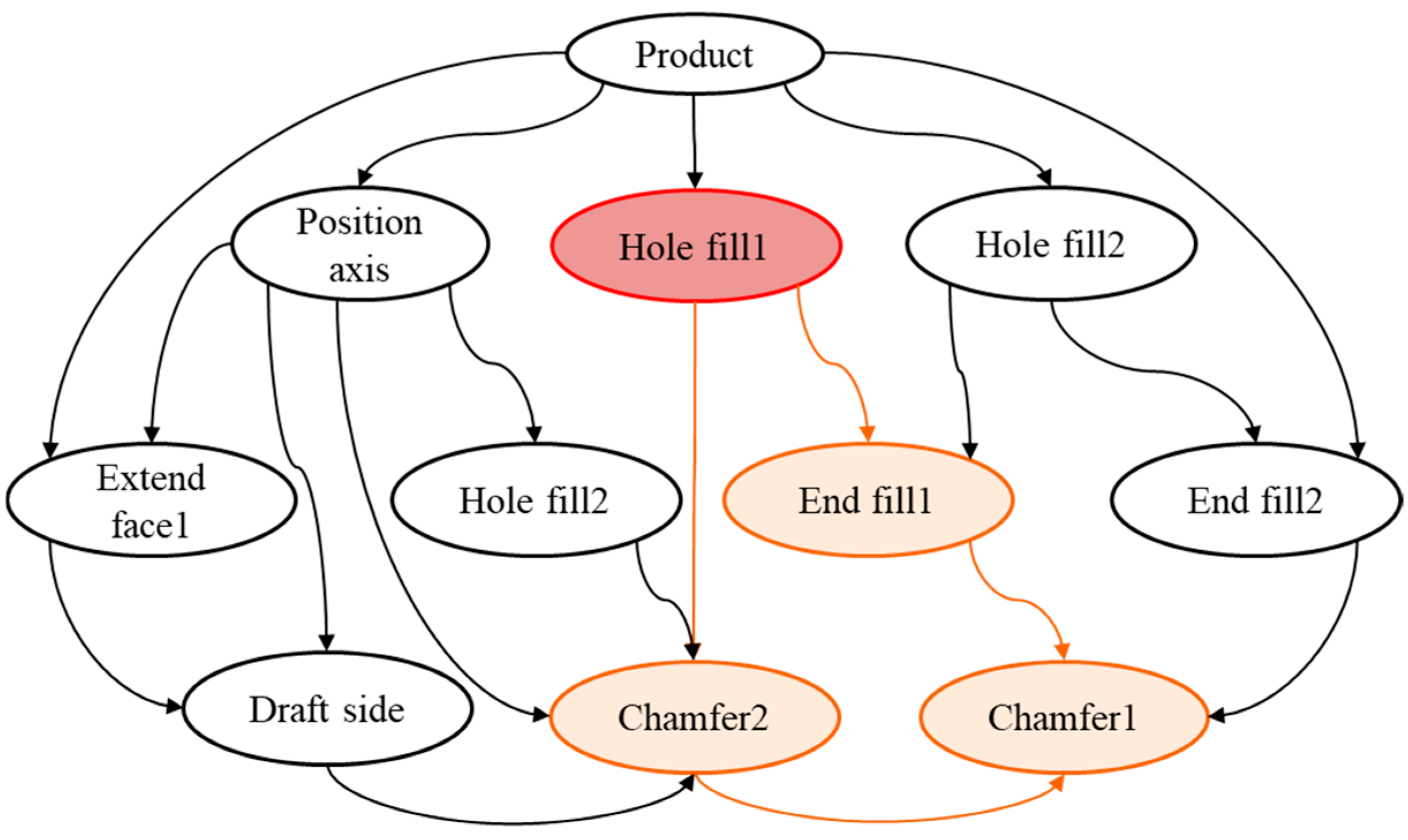
For the partition-based die face design, the die face is usually composed of dozens of faces after hundreds of geometry operations. Consequently, rapid or iterative die face updates remain highly challenging when using only a commercial CAD system. As shown in Figure 2, the parametric relationships of the die face patches are many-to-many (M:N). Updating a single feature may affect multiple features within the die face update chain, making it difficult to control both the update process and update errors. During the remodeling process, modifications to the aircraft skin components lead to updating errors caused by unstable topological elements (i.e., vertexes, edges, face) and features. Marcheix D employed persistent naming in CAD/CAE model lifecycle management and synthesized existing solutions to maintain consistent identification of geometric entities. Nevertheless, this method exhibits limitations such as poor robustness against complex topological changes and potential inefficiencies when handling large-scale assembly models [21]. Ledermann C proposed an integration method of CAD and CAE for aircraft skin design, which significantly improves the efficiency of preliminary aircraft skin components [22]. In knowledge-based engineering (KBE) systems, the updating process models, which uses relevant process parameters or knowledge, relies heavily on the parametric mechanisms of CAD systems. However, these methos fail to meet the requirements when addressing complex topological changes or variations in feature quantities. Furthermore, KBE systems are unable to dynamically adjust surfaces during the surface generation stage [23,24,25,26].
To address the challenges pertaining to the automatic design and robust updating of die faces, a die design methodology for aircraft skin components based on the Hierarchical Hybrid Association Method (HHAM) is proposed in this paper. The primary advantages of the proposed HHAM are embodied in three key aspects. First, a hybrid association mechanism is incorporated to strength the relationships among different modules of aircraft skin die face design workflow, solving the updating failures caused by variations in topologies and features. Second, geometry algorithms for aircraft skin die face, such as the wireframe model, improve both the quality and efficiency of surface generation. Third, a design process-oriented updating mechanism and a systematic error handling mechanism are developed, ensuring the updating stability and operational efficiency of the developed system. The paper is organized into the following sections:
  • Section 1 presents the die face design methods for aircraft skin components and analyses the key factors affecting the robustness and quality of the automated die face design for aircraft skin components.
  • Section 2 elaborates the proposed Hierarchical Hybrid Association Method (HHAM) for automatic die face design for aircraft skin components, and elaborates in detail on the hybrid association method for inter-module or inter-feature relationships.
  • Section 3 elaborates the key geometry algorithms for the HHAM-based intelligent system, including wireframe modeling for die face design.
  • Section 4 presents the practical application of the intelligent die face design system developed on the CATIA platform in two aircraft manufacturing enterprises.
  • Section 5 summarizes conclusion of the HHAM-based intelligent die face design system for aircraft skin components and outlines potential future research directions.

2. Methodology of Intelligent Design for Die Face Design

2.1. Structure of Die Face for Aircraft Skin Components

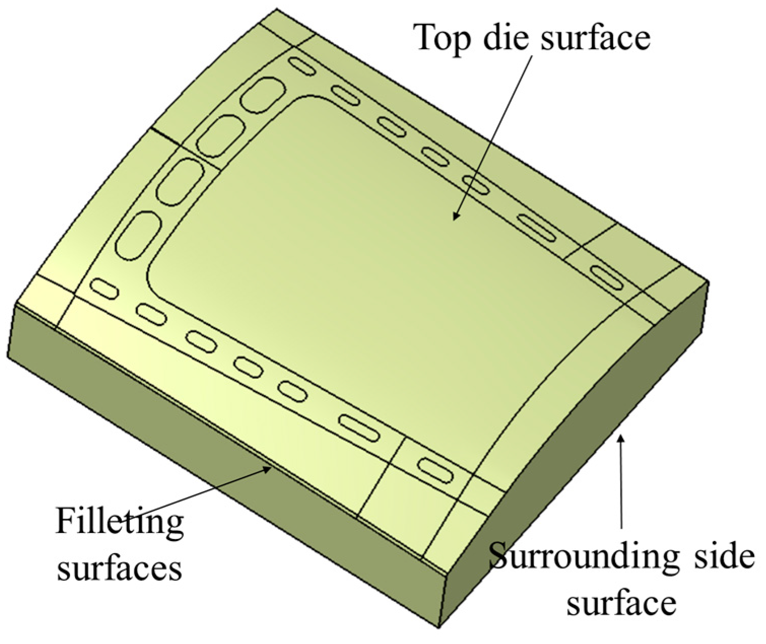
As shown in Figure 3, the die face structure for stretch forming of aircraft skin components consists of a top die surface, surrounding side surfaces, and filleting surfaces; these are described as follows:
  • Top die surface: As the core reference surface for stretch forming of the aircraft skin components, the top die surface is a precision-machined surface that provides precise shape support, ensuring the aerodynamic contour accuracy and surface finish quality. The basic shape of the top die surface is generated by different geometric operations, including hole filling, boundary filling, and boundary extension.
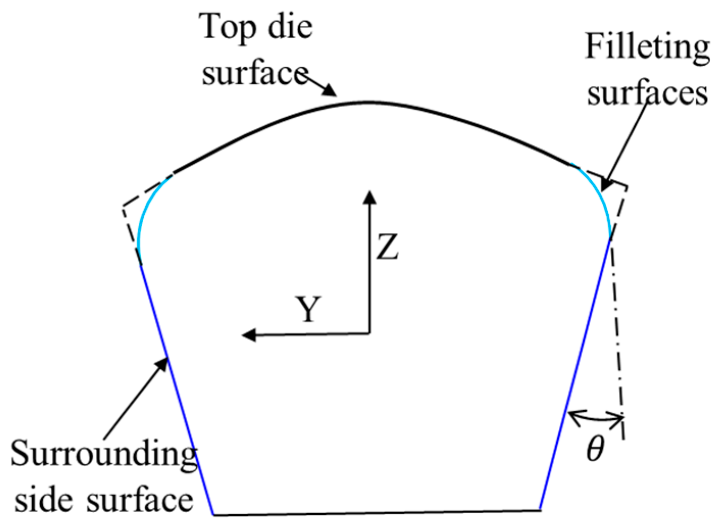
  • Surrounding side surface: These inclined surfaces (the surrounding surfaces) play a crucial role in providing motion space for the side clamps during stretch forming of aircraft skin components and enabling sufficient plastic deformation of the aircraft skin workpiece. The inclination angle typically ranges from 3° to 15°, which is adjustable in accordance with the material ductility and structural complexity of aircraft skin components. Furthermore, the inclined structure helps mitigate friction, surface scratching, and springback during the forming process.
  • Filleting surface: The fillet surfaces consist of fillets at the junctions between the top die surface and the surrounding side surfaces and fillets at the outer edge corners of the surrounding side surfaces. These fillets, with a fixed radius, eliminate the sharp edges of the aircraft skin die face. Such filleted surfaces not only mitigate surface stress concentration but also inhibit crack initiation and surface scratching of stretch forming, thereby ensuring the safety and stability of the forming process.

Design Flow of Aircraft Die Face

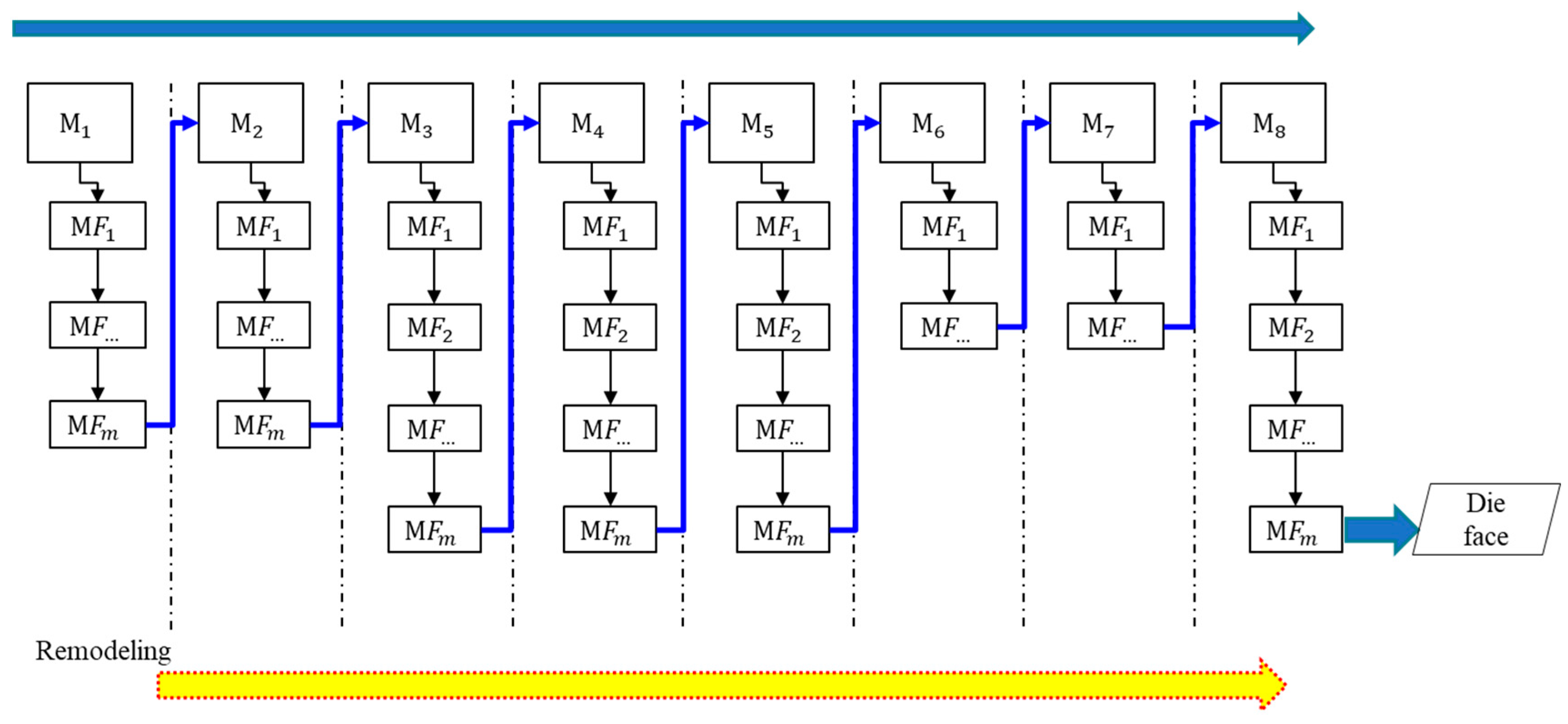
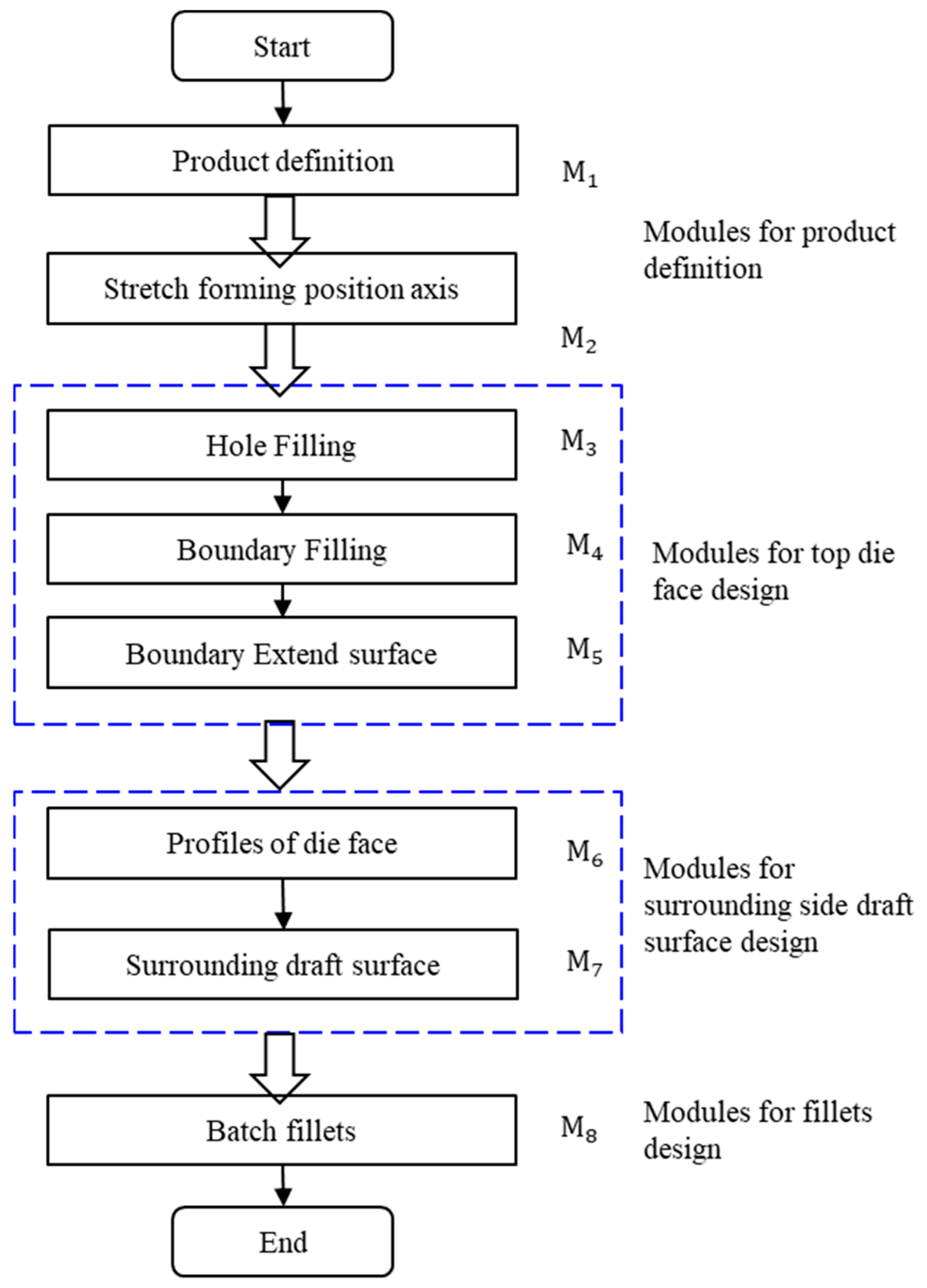
Based on the main structures of the aircraft skin die face, the die face design process is decomposed into eight modules, namely product definition ( M 1 ) , stretching coordinate system design ( M 2 ), hole filling ( M 3 ), boundary filling ( M 4 ) , boundary extending ( M 5 ), die face profile design ( M 6 ), surrounding side surfaces design ( M 7 ), and batch filleting ( M 8 ), as shown in Figure 4.
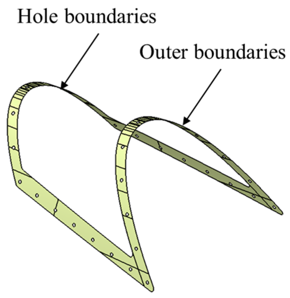
Product definition serves as the initial stage of the HHAM-based intelligent die face design system for aircraft skin components, aiming at integrating discrete surface patches. Corresponding to M1, the inner and outer boundaries of the aircraft skin components are automatically extracted based on edge topological connections.
The stretch forming coordinate for aircraft skin components has significant influence on the forming quality, as it directly affects critical forming parameters such as stretching depth and wrapping angle. An improper stretch coordinate system for aircraft skin components (corresponding to M 2 ) can lead to unstable clamp movement and inferior forming quality. The methods for determining the stretch coordinate system of aircraft skin components are categorized into two types according to the minimum height of the components:
(1)
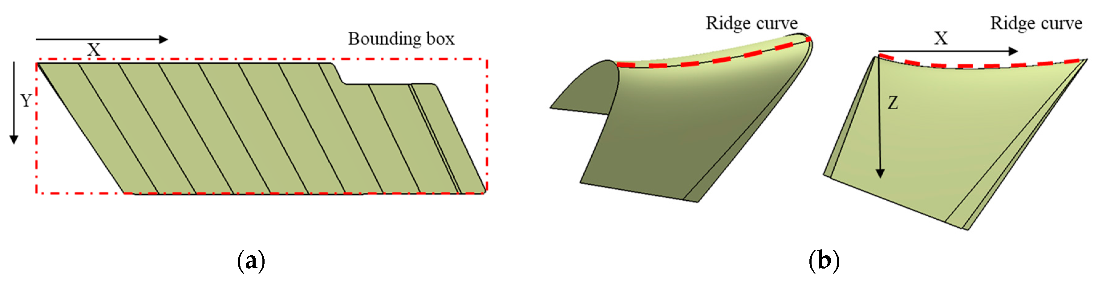
Figure 5a shows the first type of method, which is applicable to aircraft skin components with small height. For such components, the stretching coordinate system is established based on their minimum bounding box. The X-axis is aligned along the long edge of the bounding box, the Y-axis along the width edge, and the Z-axis is determined by the cross product of the X-axis and Y-axis (i.e., Z = X × Y).
(2)
Figure 5b shows the second type of method, applicable to aircraft skin components with large heights. For such components, the stretch coordinate system is established based on the ridge curve. The X-axis is oriented along the direction from the start point to the end point of ridge curve, the Z-axis is perpendicular to the X-axis on the plane of the ridge curve, and the Y-axis is determined by the cross product of Z-axis and X-axis (i.e., Y = Z × X).
As shown in Figure 4, the modules dedicated to the top die face for aircraft skin components (i.e., Modules M 3 , M 4 , M 5 ) function as the core modules that determine the geometric shape of aircraft skin die faces. The generation methods of these modules, based on wireframe modeling tailored to aircraft skin die face design, will be discussed in Section 3.
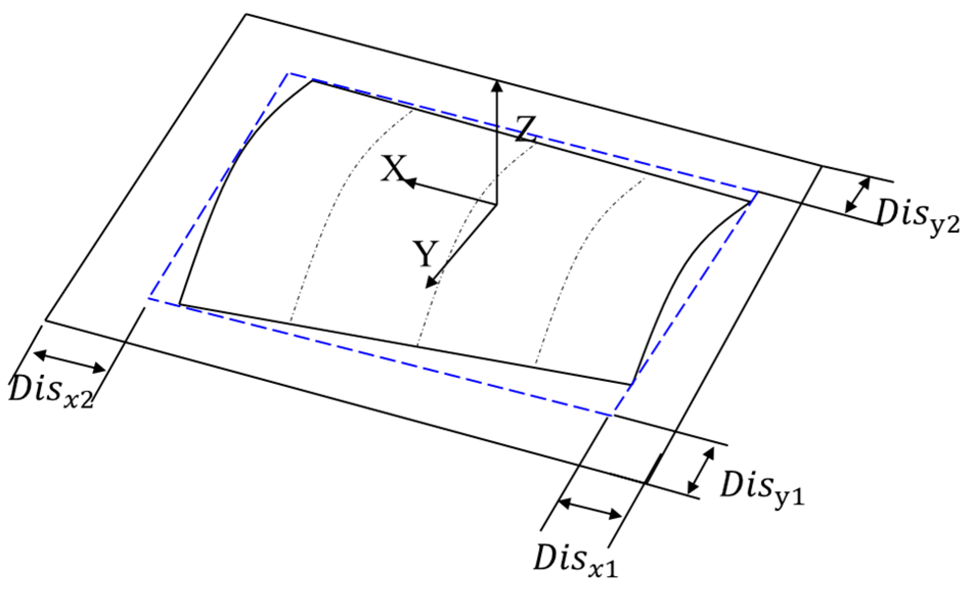
The aircraft skin die face profile is the outer geometric constraint of the die face. As shown in Figure 6, the outer boundary of the aircraft skin die face is a rectangular shape slightly larger in size than the minimum bounding box (marked by the dashed blue frame) of the aircraft skin components under the stretch coordinate system. All offset distances along the X and Y directions ( D i s x 1 , D i s x 2 , D i s y 1 , and D i s y 2 ) are automatically determined based on the dimensions of aircraft skin components and the design criteria for aircraft skin die face design.
The surrounding side surfaces (corresponding to M 7 ) and the fillet surfaces (corresponding to M 8 ) of the aircraft skin die face are as illustrated in Figure 7. In particular, the surrounding side surfaces are generated by draft surface functions of commercial CAD software along the Z-axis of the stretch coordinate system with a draft angle θ . Meanwhile, the filleting surfaces are generated using the fillet function in commercial CAD software for all sharp edges of the die face.

2.2. Robust and Hierarchical Updating Methodology for the Intelligent System

2.2.1. Structure and Updating Methodology of Module Design

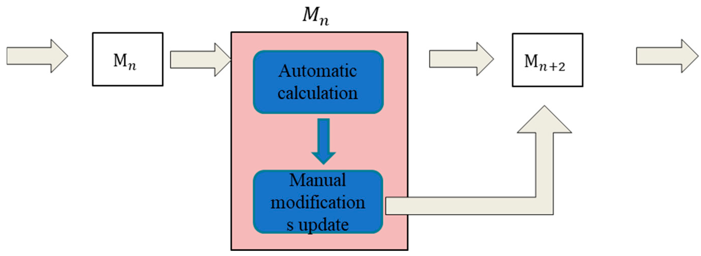
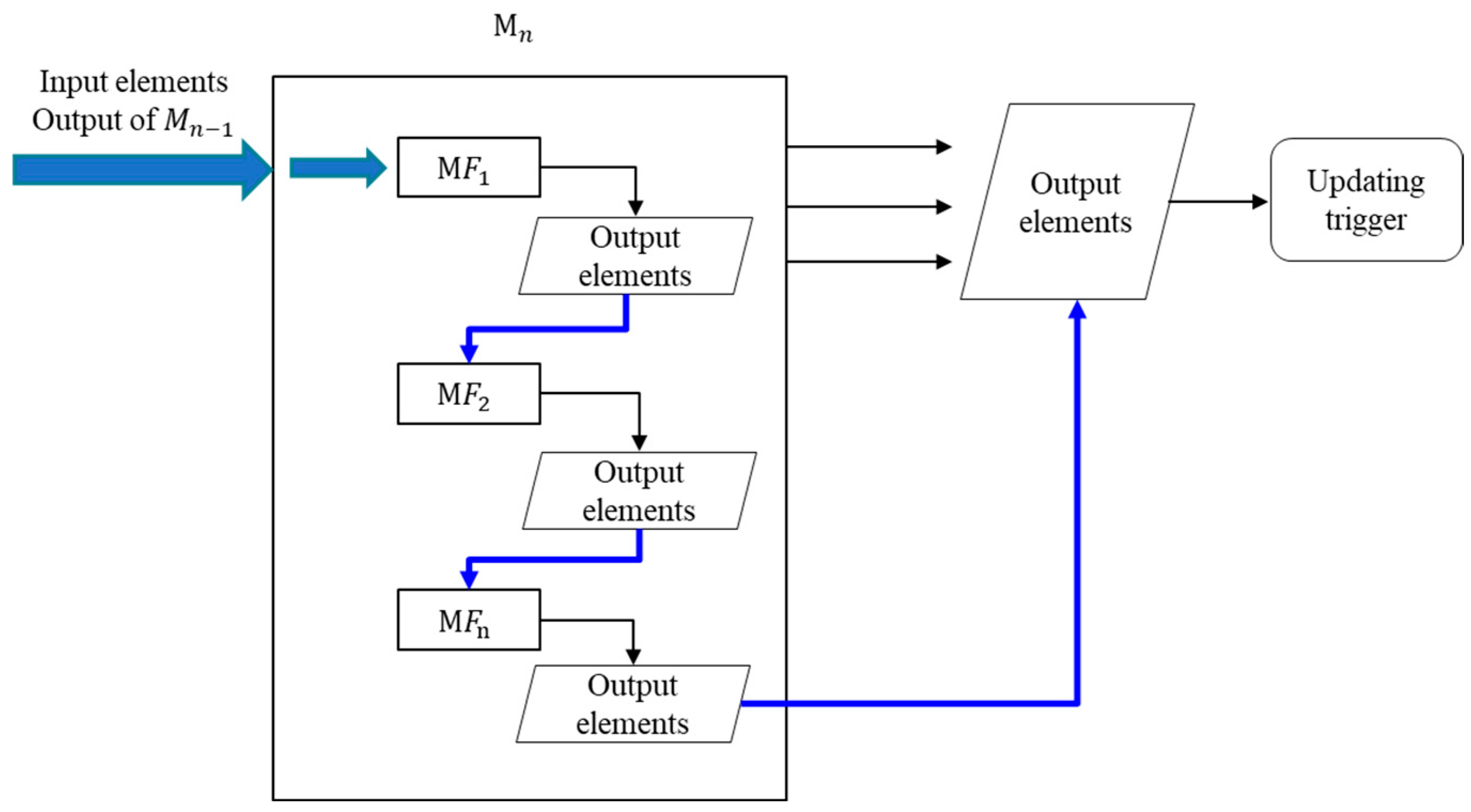
Modularization is the foundation basis for hierarchical updating mechanisms in the intelligent design system of aircraft skin components. As shown in Figure 8, the basic module structure consists of four components: input elements, output elements, feature management, and updating trigger.
The input elements, output elements, and updating trigger of M n are key elements to ensure the robust updating process of aircraft skin die face design modules. The input elements of M n are restricted to the output elements of the previous module M n 1 in the aircraft skin die face design. Additionally, the input elements of the first feature ( M F 1 ) are consistent with those of M n . The output elements of M n are new features that retain geometric consistency with the final geometry as those of final feature M F n . The new output feature ensures that the output elements do not depend on any specific feature of M n , avoiding updating errors caused by variations in the number of features. The updating trigger of M n in the aircraft skin die face design system acts as an updating signal control unit. Upon the successful updating of M n , this updating trigger is activated to trigger the updating process of the subsequent Module M n + 1 .
The mitigation of error propagation between modules in updating chains of the aircraft skin die face design system is realized by complementary technical mechanisms, which are deeply integrated into the hierarchical hybrid association architecture of HHAM. The intelligent die face design system for aircraft skin components adopts hierarchical isolation and threshold constraint in each module for error control. Synergistically, each module is configured with an independent error tolerance threshold, with the geometric deviation constrained to ≤1 × 10⁻⁶ mm in magnitude. In the intelligent die face design system, errors generated in the previous module are contained within the current modules by real-time threshold monitoring, and such errors will not propagate directly to subsequent modules, thereby achieving error isolation between modules. A “hard limit” is adopted for critical modules (e.g., M 3 ) in the aircraft skin die face system. Specifically, once the error surpasses the error tolerance threshold, the critical module automatically pauses its update and triggers correction action.
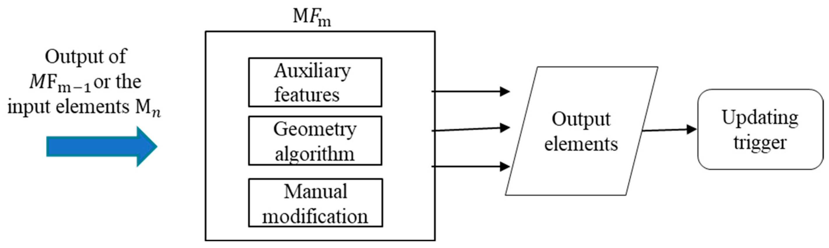
As shown in Figure 9, the structure of feature M F m in the aircraft skin die face design system is similar to the module without feature management components. The input elements of feature M F m possess two primary sources: one is the output elements of the previous feature M F m 1 ; the other refers to the input elements of M n when m = 1. Typically, a single module M n encompasses multiple features (MFs), as impossibility of accomplishing the design module in a single step. The updating process of features follows a logic analogous to the inter-module updating process of the hierarchical updating mechanism. In particular, in the aircraft skin die face, if M F m is the last one, its updating trigger will be activated to trigger the updating process of output elements for M n . There are three specific components of feature M F m including auxiliary features, geometry algorithms, and manual modifications. Auxiliary features, such as the control curves, are the intermediate features to improve the surface generating success rate and surface quality. Geometric algorithms (i.e., automation boundary region recognition) enhance the robustness of the aircraft skin die face intelligent design system. Manual modification information is employed to synchronize manual adjustments implemented during the remodeling process, ensuring the consistency of iterative design for aircraft skin components.
It is impossible for the intelligent die face design system of aircraft skin components to accomplish the aircraft skin die face design independently under all engineering working conditions. Manual operation by designers is invariably required to ensure the high geometric accuracy of the aircraft skin die face. As shown in Figure 10, the updating flow incorporates not only the automatic procedure, but also manual modifications. Taking M 2 (stretching coordinate system design) for aircraft skin die face as an example, the stretching coordinate system can be automatically calculated by the ridge curve or minimum bounding box detailed in Section 2.1. However, the stretching coordinate system may require manual modifications (i.e., coordinate rotations or translations) in practical engineering applications, and these modifications are recorded as a matrix transformation. The updating procedure of M 2 is a two-step mechanism: the first step is the automatic calculation based on predefined algorithm; the second step is affine matrix transformation that incorporates the manual modification information. This two-step updating mechanism ensures the flexibility of manual intervention while maintaining the robustness of the updating process. When manual modifications conflict with automatically updating matrices, the system prioritizes manual modifications as the primary input.
Manual modification is primarily required for cases with surface quality defects of the aircraft skin die face, as the geometric configuration and quantity of die face control curves in the wireframe model exert a direct influence on the surface geometric quality. The density and geometric shape of automatically generated control curves may fail to meet the design requirements in specific engineering scenarios, rendering manual modification indispensable for surface quality optimization.

2.2.2. Robust Error Process of the Intelligent System

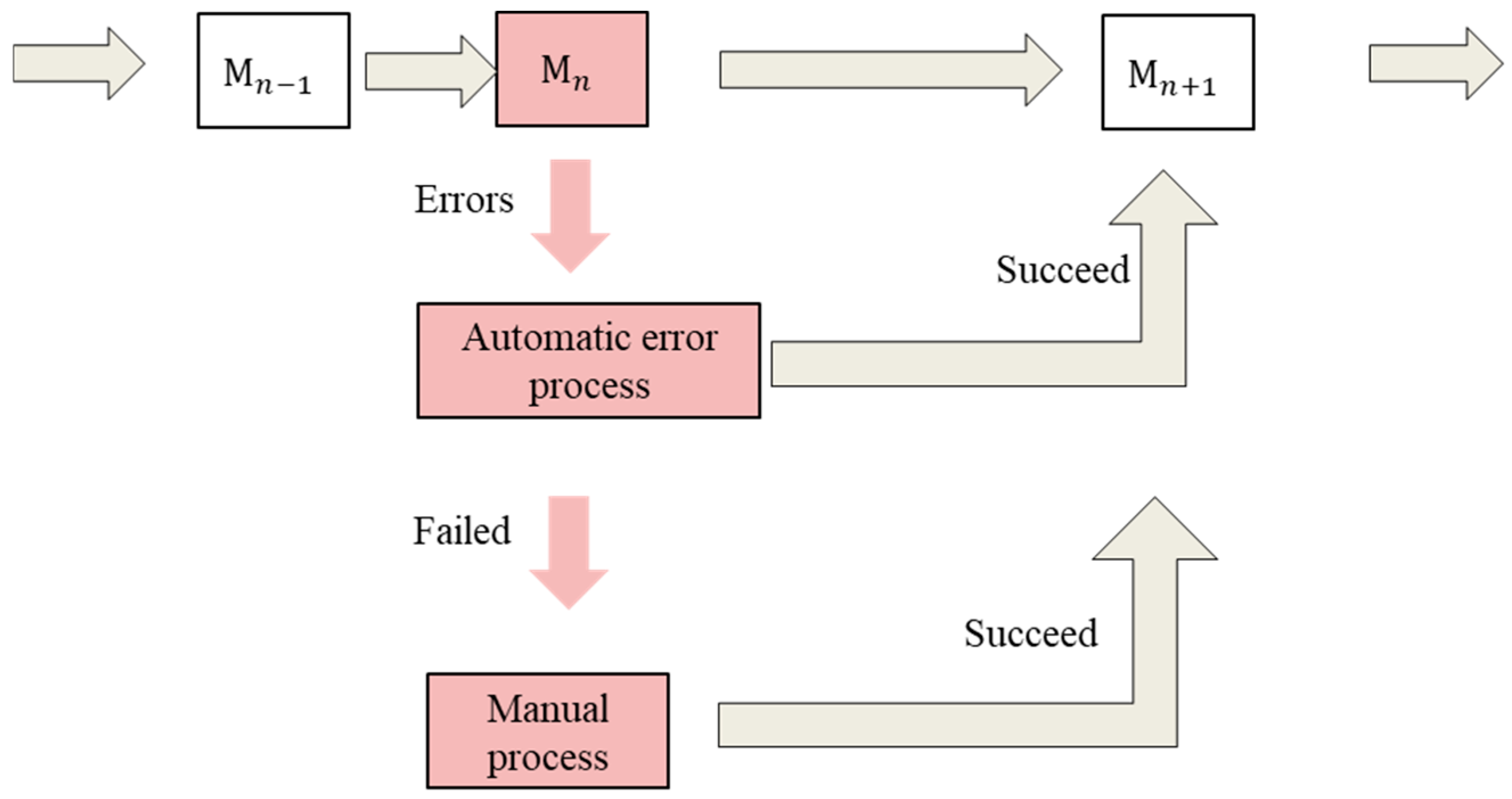
The error handling mechanism of the hierarchical updating flow is critical to the robustness of the intelligent aircraft skin die face design system, as it is impossible that there are no error occurrences in the die face design process. As shown in Figure 11, M n is the current updating module. If M n completes the updating process successfully, the updating flow proceeds sequentially to M n + 1 . In contrast, if M n fails to complete the update process, M n will activate an automatic error handling process, which is described in a subsequent paragraph. In this mechanism, if the update is successful after automatic error handling, the hierarchical updating flow continues to M n + 1 ; if the automatic error handling remains ineffective, the manual error handling procedure will be triggered specially for M n + 1 to resolve the updating failures.
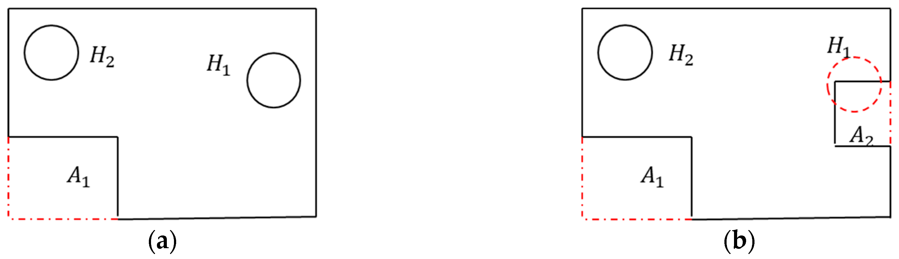
In remodeling process of the aircraft skin die face design, the number of features may vary (i.e., decrease, increase) due to the iterative design of aircraft skin components or the stretching forming process. As shown in Figure 12, there are two holes ( H 1 , H 2 ) and one boundary filling region ( A 1 ) in the original product, whereas there is only one hole ( H 1 is deleted marked by the dashed red circle) and two boundary filling regions ( A 2 is added) in the revised product. The feature associated with H 1 suffers updating failure errors and the newly added A 2 cannot be filled automatedly by CAD software without manual operations. The feature management mechanism addresses the problem using a specific algorithm. Hole module ( M 3 ) can automatedly separate the input elements by grouping die face geometric curves in the intelligent die face design system. Additionally, in the intelligent die face design system, M 3 automatically matches the hole features with existing geometric features based on integrated new and old geometric information, including input geometric features, topological features, and relative positional relationships. The feature with hole H 1 is deleted automatically to avoid the updating error. Concurrently, A 2 is recognized automatically in M 4 using the rolling collision detection algorithm, which will be discussed in Section 3.2 in this paper. Subsequently, a new boundary filling feature is added to fill A 2 .
To improve the surface quality and the success rate of surface generation for the aircraft skin die face, Module M 3 , Module M 4 , and Module M 5 adopt the wireframe surface modeling method which contains guide curves and control curves. The specific generation of wireframe modeling will be discussed in detail in Section 3.1. However, CAD features or the topological entities are not stable by commercial CAD software; thus, the input elements of the modules and features cannot be directly associated with CAD topologies and features. To address this issue, a hybrid association method is proposed in the intelligent die face design system for aircraft skin components.
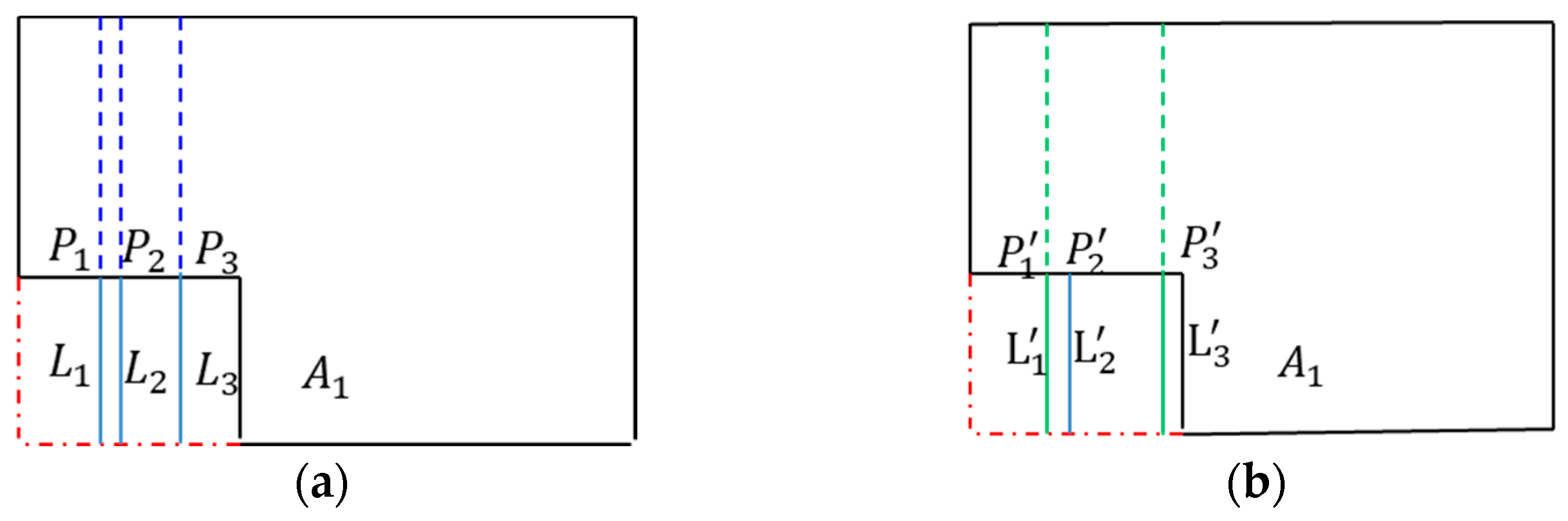
As shown in Figure 13, lines L 1 , L 2 , and L 3 are the control curves for boundary fill region A 1 of the aircraft skin die face. The vertex points of those control lines correspond one-to-one to the original topological points P 1 , P 2 , and P 3 , respectively. After aircraft product revisions, the P 1 remains unchanged, P 2 is deleted, and the position of P 3 is adjusted. In the wireframe modeling updating flow of the intelligent die face design system, the relationship between control curves and topological points is first retrieved. For the persistent topological relationship (i.e., P 1 and P 3 ), the control line positions L 1 and L 3 are directly updated based on points P 1 and P 3 . For non-existent topological relationships (i.e., P 2 ), the automatic re-linking method is adopted for the association processing of P 2 . P 2   (updated topological point corresponding to P 2 ) is determined as the point that minimizes the distance to the model boundary ∂Ω, and the position of the corresponding control curve L2 is updated synchronously based on P 2 to ensure the geometric continuity of the wireframe model.
P 2 = min d ( p , Ω )
min d ( . , . ) represents the minimum distance of points and the model boundary.
If a vertex resides within the neighborhood domain N( P 2 , δ), coordinates of P 2 are adjusted to match this vertex.
V P 2 2     δ
where δ is the neighborhood threshold and V Ω v e r t e x .
Furthermore, if additional topological vertices are present on the new boundaries of the aircraft skin die face, the dedicated module in the intelligent die face design system for aircraft skin components automatically incorporates control curves to enhance the surface geometric quality and ensure geometric continuity.
Based on the aforementioned analysis, the update process proceeds step-by-step with a robust error handling mechanism in the intelligent die face design system. The overall updating workflow of the intelligent system is as shown in Figure 14.

3. Robust Geometry Algorithm of Surface Generation

3.1. Adaptive Wireframe Modeling for Surface Generation

The adaptive wireframe model design method involves the abstraction of modeling surface features into a hierarchical wireframe model, which serve as the surface “skeleton”. The geometric rationality of the surface can be quickly evaluated by the lightweight model (“skeleton”). The wireframe modeling method relies on discrete point fitting to characterize complex curved surfaces. For highly anisotropic curvature patterns with significant curvature distributions with significant discrepancies across curvature variation rates directions, it is challenging to balance fitting precision and data redundancy. Dense control curves hinder smooth continuity between multi-directional curves, leading to the inability to precisely characterize the anisotropic curvature distribution. The generation method for dense control curves is elaborated in detail in Section 3.3. During the wireframe model update, topological and geometric variations in the original surfaces may lead to update failure. The solving method for the unstable updating process is in Section 2.2.
For complex surfaces, their shapes can be conveniently and timely edited by adjusting wireframe curves and feature parameters. Additionally, the wireframe design model integrates a hierarchical structure representing modeling rules, enabling them to adaptively adjust under different constraint conditions. This significantly improves the updating efficiency and stability.
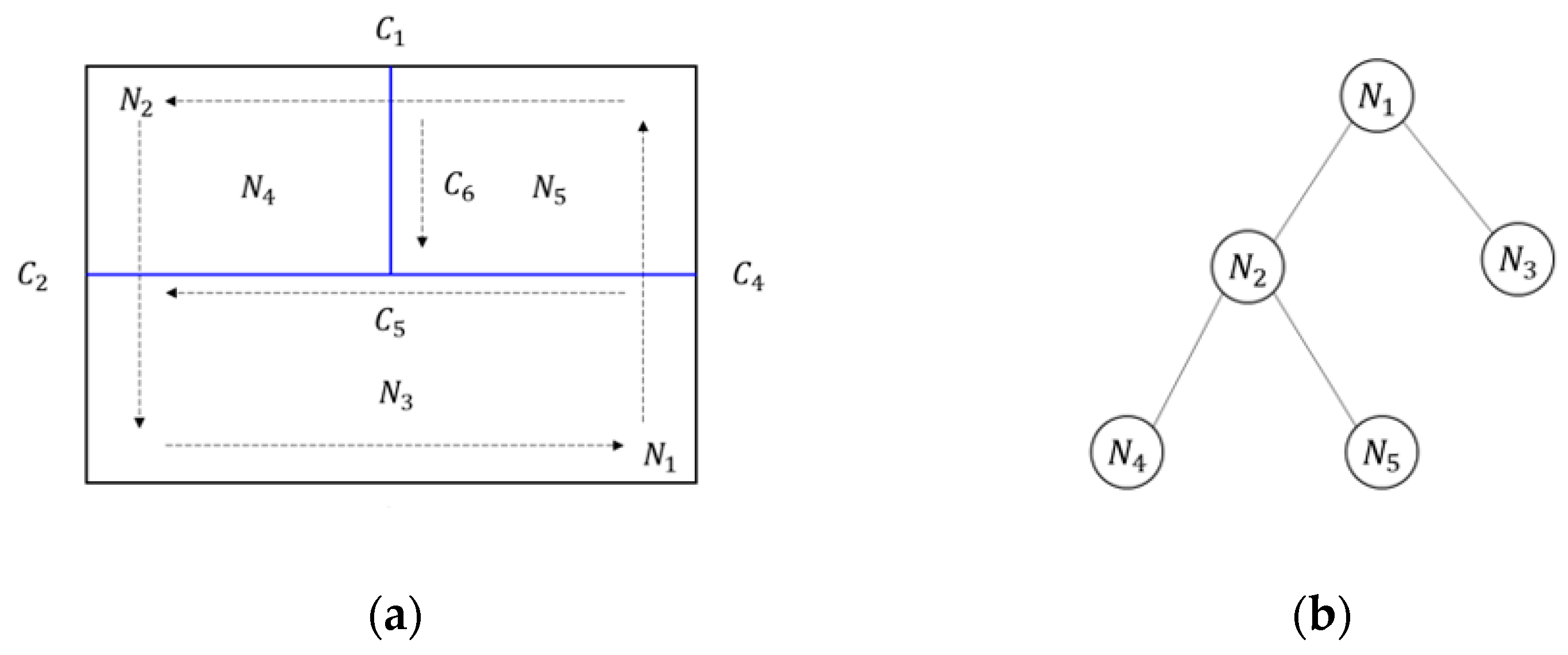
The curved wireframe is a curve-based skeleton, either automatically generated by algorithms or manually constructed by designers, functioning to control the geometric shape of surfaces. As illustrated in Figure 15, the elements of the curved wireframe consist of a series of directed curves, categorized into boundary curves (black curves) and control curves (blue curves). Boundary curves must form closed loops to define the domain of surfaces: curves C 1 ~ C 4 constitute a directed closed loop, with the surface located on the left side of the loop. Control curves are constructed on boundary curves to accurately regulate the internal shape of the surface: the endpoints of control curve C 5 reside on boundary curves C 2 and C 4 , dividing the surface domain into two patches; the endpoints of control curve C 6 reside on boundary curve C 1 and control curve C 5 , further subdividing one of the sub-domains.
Association information records the dependence relationships between geometric elements in the wireframe model, and a tree structure is adopted to organize and store such association information. Each tree node represents a surface domain, comprising one outer loop and several inner loops (if any exist). If the current node is not a leaf node, it further incorporates control curves that subdivide the current design domain; a leaf node corresponds to the resulting surface. As shown in Figure 15b, N 1 is the root node of the association information tree. N 1 is subdivided into N 2 and N 3 by the control curve C 5 , and N 2 is subdivided into N 4 and N 5 by the control curve C 6 . N 1 and N 2 are non-leaf nodes, recording their respective control curves C 5 and C 6 ; N 3 , N 4 , and N 5 are leaf nodes, corresponding to the resulting faces, respectively. Non-leaf nodes can derive the resulting surface by traversing all leaf nodes under them, and leaf nodes can acquire sibling nodes and dividing curves by querying their parent nodes.
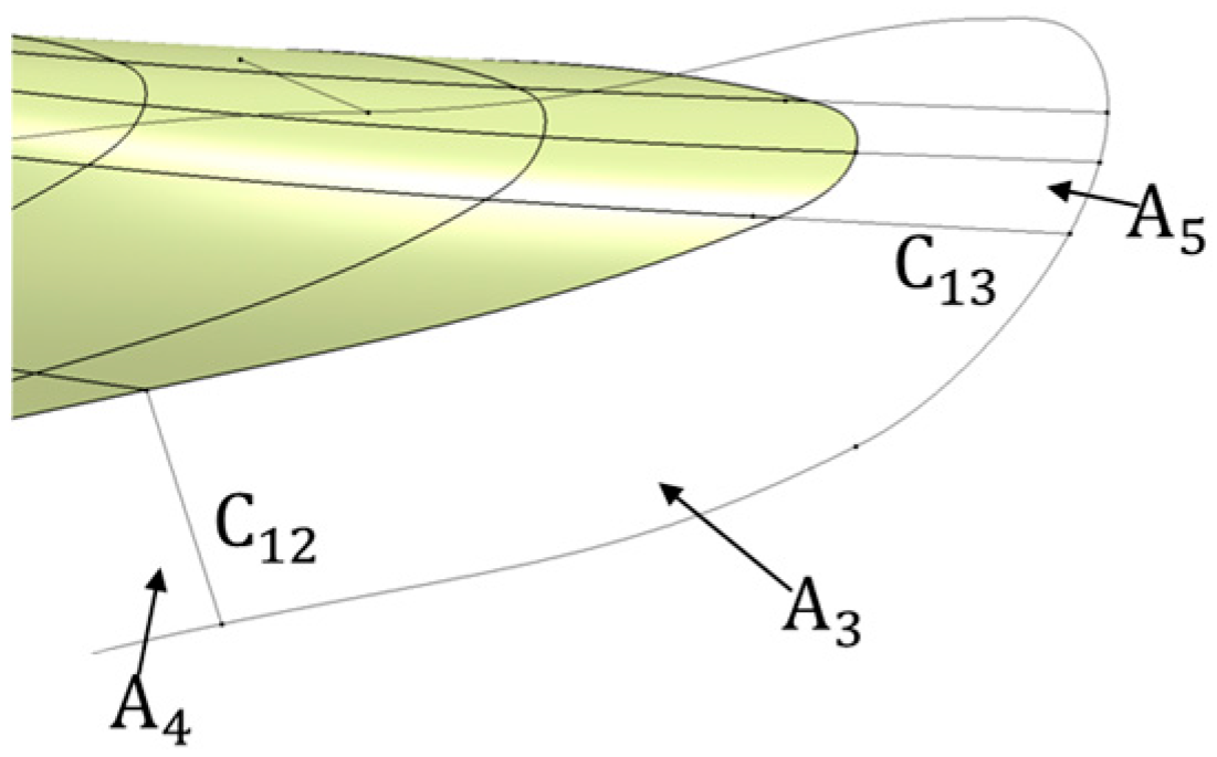
The surface generation order determines the dependence relationships of the surface patches, which in return affects the surface morphology. The surface generation order follows the simplicity-first principle, where the simplicity of each surface patch is quantified according to the influence weights of geometric information associated with the common boundary edges between adjacent design domains. As shown in Figure 16, the boundary curves of A 3 are more complex with height-direction undulations. If A 3 is generated first, the constraints exerted by this surface on common boundaries C 34 and C 35 are more stringent and complex, potentially leading to deformation of surface patches A 4 and A 5 . Therefore, the optimal surface generation order is A 4 , A 5 , A 3 .

3.2. Automatic Boundary Filling by Rolling Collision

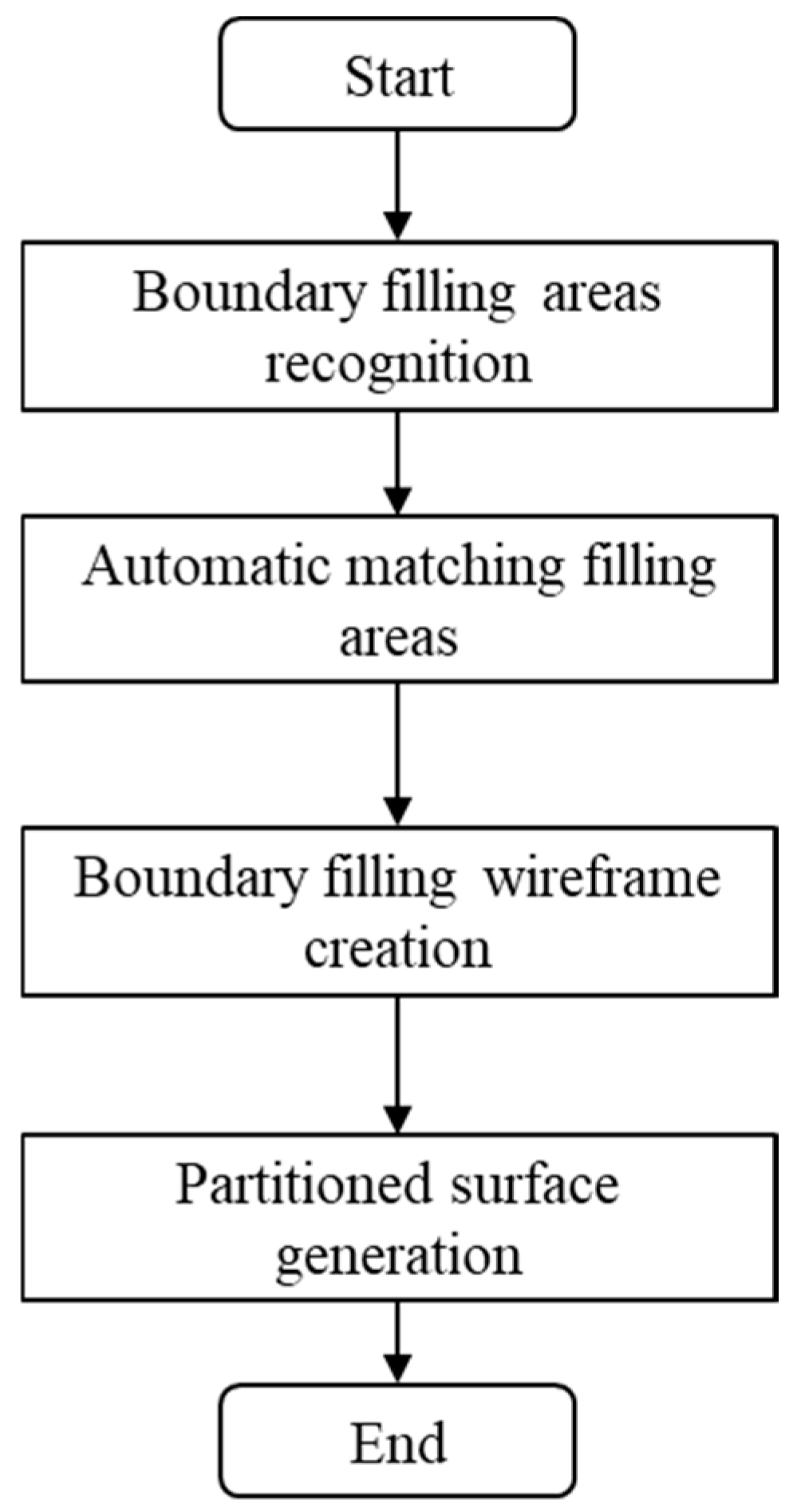
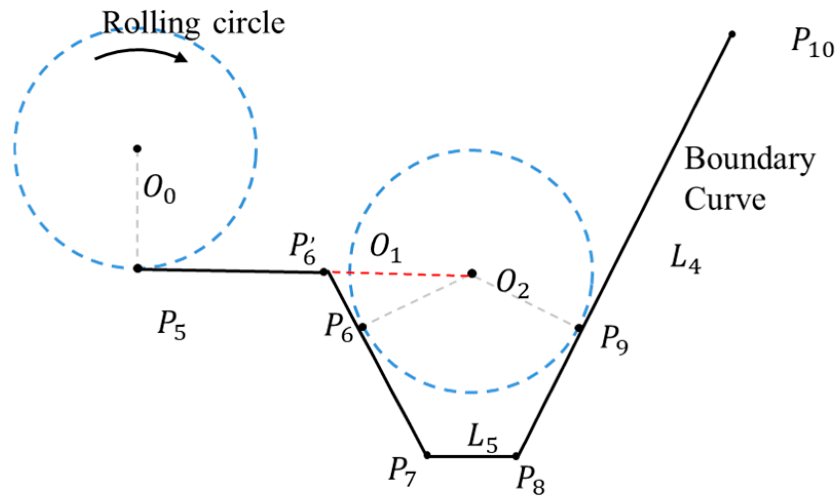
The boundary filling region recognition method is critical to the robustness of boundary filling management of M 4 . The design workflow of boundary filling is illustrated in Figure 17. Specifically, boundary filling region recognition adopts the rolling detection process of a circle along the boundary curve, and this rolling detection algorithm is one of the classical algorithms applied in 2D curve offsetting [27,28,29,30,31,32]. As shown in Figure 18, when the rolling circle moves to P 6 , the circle intersects with the line L 4 at P 9 , and the boundary filling curve is from P 1 to P 4 . Considering the original topology of the original boundary curve, P 6 is repositioned to P 6 , , which is the vertex with minimum distance to P 6 within the local neighborhood. The rolling collision algorithm proposed in this paper realizes the collision detection for 3D curves by continuous transformation of the local coordinate system constructed on the 3D curves. Specifically, the Z-axis of the local coordinate system is defined as the surface normal vector corresponding to each discrete point on the boundary curve.
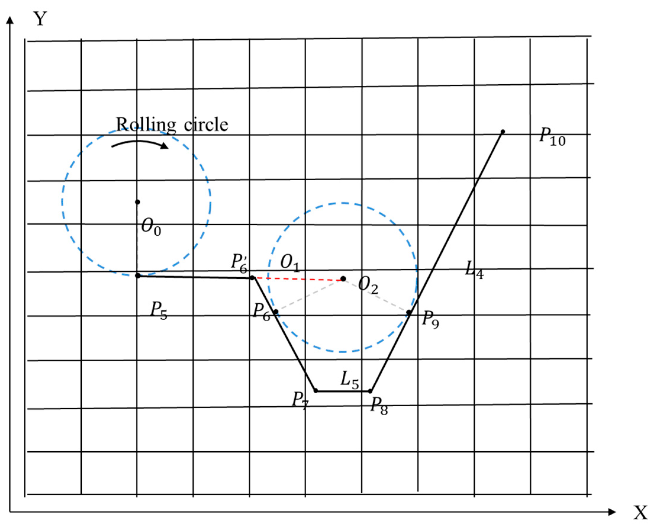
The boundary curve consists of n discrete points and n − 1 connecting segments. In the unoptimized search scenario, traversal of these points and segments yields a time complexity of O ( n 2 ). As shown in Figure 19, for the acceleration, a spatial grid method is adopted to reduce the single search complexity from O(n) to O(logn). Therefore, the algorithm complexity is optimized to O(n·logn).
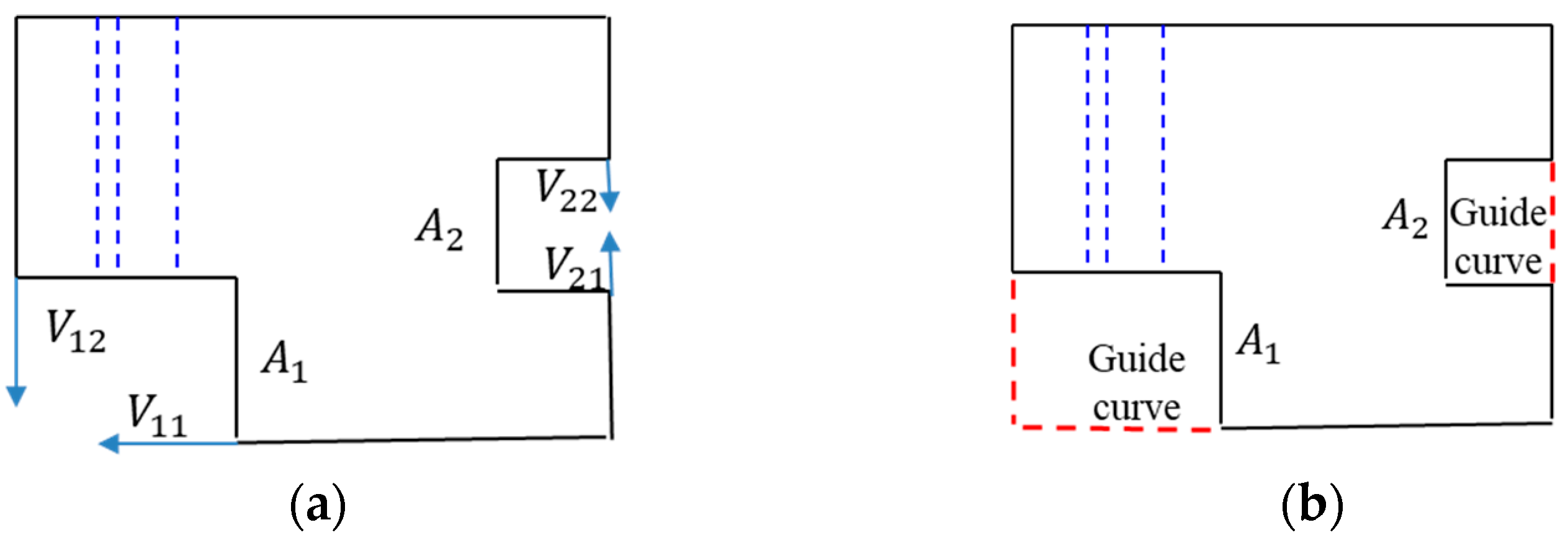
As in Figure 20, there are two types of boundary curves of the filling region boundaries, with the distinction residing in the tangent direction angles at boundary points. The first type consists of curve segments where the tangent directions of adjacent boundary points are consistent (i.e., A 1 ). The region is defined when the angle between vectors V 11 and V 12 is less than 160°; the other type is formed with one straight line segment (i.e., A 2 ), which is applicable when the angle between vectors V 21 and V 22 is greater than 160°.
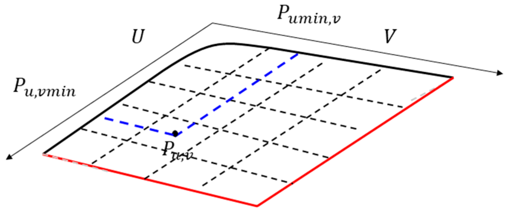
Height interpolation processing for the boundary connection curve is necessary due to height-direction undulations in the boundary filling region. Positional height interpolation calculations are executed according to the proportion of the inner boundary curve, which guarantees the geometric smoothness and positional accuracy of the generated boundary connection curves, as shown in Figure 21.
P u , v ( Z ) = a ( α ) · P u , v m i n ( Z ) + b ( β ) · P u m i n , v ( Z )
P u , v ( Z ) is the Z-coordinate of point P u , v ; a and b are the weight coefficients; P u , v m i n ( Z ) and P u m i n , v ( Z ) are the height coordinates of boundary points.
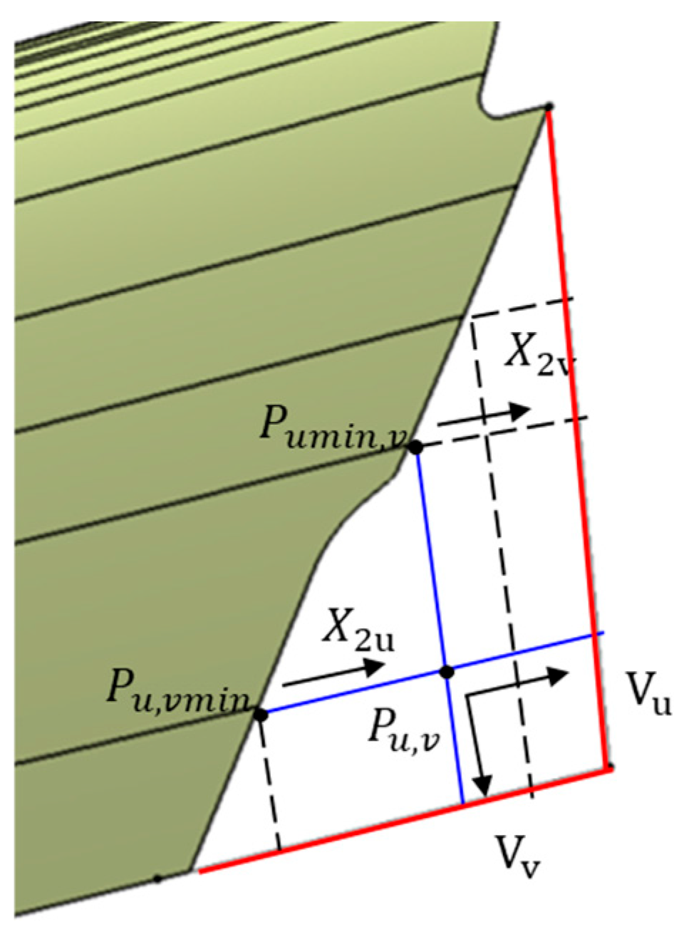
For the boundary filling surface patch, the height interpolation coefficient significantly affects the interpolation result. To ensure the filling surface closely adheres to the morphological trend of the original surface, the interpolation coefficient is strongly correlated with the minimum principal curvature directions. As shown in Figure 22, the boundary filling surface achieves optimal geometric quality when the positional height value P u , v ( Z ) is almost consistent with P u , v m i n ( Z ) (a = 1, b = 0). Specifically, the minimum curvature direction of P u , v m i n is X 2 u , while the minimum curvature direction of P u m i n , v is X 2 v ; the wireframe directions of P u , v are V u and V v . The included angle between V u and X 2 u is α , and that between V v and X 2 v is β. The weighting coefficients are calculated as follows:
a   = f a b s ( 90 α ) / 90 ,   b   = f a b s ( 90 β ) / 90
The generation method for the boundary filling surface, based on overlapping partition conditions, is elaborated in Section 3.3.

3.3. Design Method of Boundary Extending

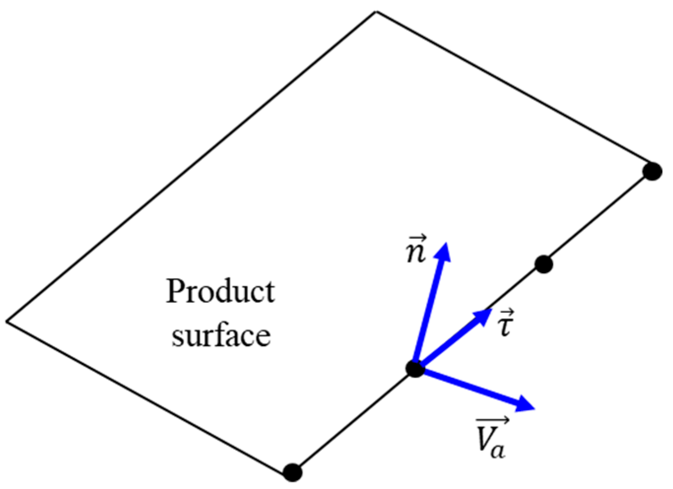
The quality of the extended surface is critical to die face design, and a wireframe modeling method is adopted for its generation. To ensure C 1 continuity of the extended surface at the boundary, the extension direction at each discrete point must lie on the tangent plane of the product surface. As shown in Figure 23, the cross-boundary tangent direction V a from the surface boundary serves as the primary extension direction. τ is the unit tangential vector of the discrete point on the surface, and n represents the unit normal vector of the discrete point on the product boundary surface. At cusp points, two basic extension directions are calculated based on the left and right tangential vectors, respectively.
V a = τ × n
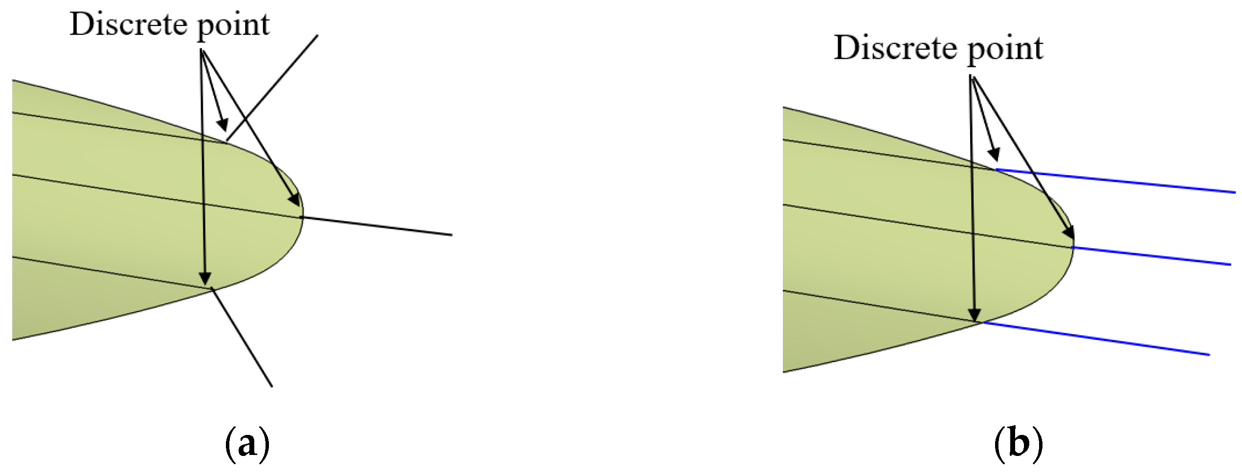
For complex spliced surfaces patches, the basic extension direction fails to adequately characterize the outward extension trend at the boundary, as shown in Figure 24a. In such cases, the extension direction is generally chosen as the direction of the minimum curvature of the surface, where the rate of the curvature change is minimal. This ensures the extension surface is aligned with the principal curvature direction, achieving a natural surface transition, as shown in Figure 24b.
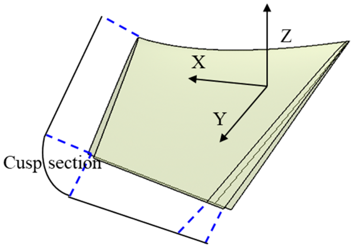
In the extension of surface boundaries, traditional segmented extension may still result in surface quality defects such as wrinkles and waves. Due to shape variations in complex boundaries, the extending surface may be amplified or concentrated after extension along the extension direction—particularly at concave and cusp positions. To address these issues, the segmentation algorithm is proposed in this paper. For complex surfaces of aircraft skin surfaces, as shown in Figure 25, segmentation based on boundary feature points (i.e., cusp points) ensures the consistency between the extension surface and the original surface. Segmentation at cusp points is intended to avoid surface wrinkling caused by the de-generation of the boundary into a single point, and arc segments are used to connect the left and right control curves.
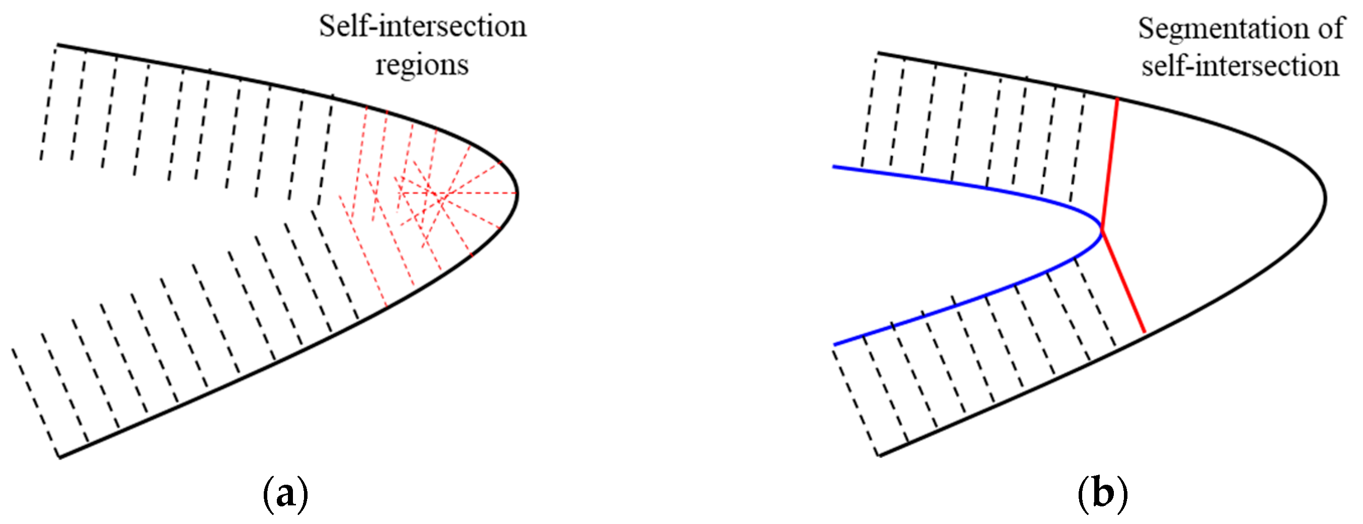
As shown in Figure 26, for the extension directions at each discrete point, the self-intersection detection algorithm for boundary control curves is utilized to detect and locate self-intersecting regions of control curves. Boundary guide curves for the filling surface are generated between the extension curves at both ends of the self-intersecting regions, and the new filling region is connected with the guide curves and the boundary segments on the original product surface. A filling surface generation method for the extension surface is adopted for these self-intersection regions, resolving the surface wrinkling defect.
For the grid formed by boundary control curves and boundary guide curves derived from surface extension, the bidirectional skinning modeling technology is used to construct the extension surface. To satisfy the C 1 geometric continuity requirement at the extension surface boundary, the cross-boundary tangent vector data at discrete surface boundary points are used to constrain the constructed extension surface. In this paper, an approximate algorithm is adopted, which involves three key steps: sampling discrete data points, determining optimal surface parameterization, and refitting the surface boundary curves. The method simultaneously achieves geometric approximation of boundary curves and the cross-boundary tangent vectors. The cross-boundary tangent vectors at the discrete points on surface boundaries are regarded as a tangent vector curve, where each cross-boundary tangent vector constitutes a discrete point on this curve. After approximation, the pole representation of the fitted new surface boundary curve is analytically derived.
C = i = 0 n N i , p ( u ) P i
The pole representation of cross-boundary tangent vectors at the surface boundary:
D = i = 0 n N i , p ( u ) Q i      
n is the total number of control points of the approximated curve, p is the degree of the approximated curve, and N i , p ( u ) is the common basis function of both the approximated surface boundary curve and the cross-boundary tangent vector on the surface boundary. P i is the discrete point of the surface boundary curve, and Q i is the control point of the cross-boundary tangent vector, where Q i corresponds to P i in a strict one-to-one correspondence, and Q i is the cross-boundary tangent vector at the discrete boundary control point P i .
The fitted approximated cross-boundary tangent vector D is added as a surface boundary constraint for constructing the extension surface by bidirectional skinning, ensuring that the extension surface satisfies the C 1 geometric continuity on the boundary.

4. Discussion

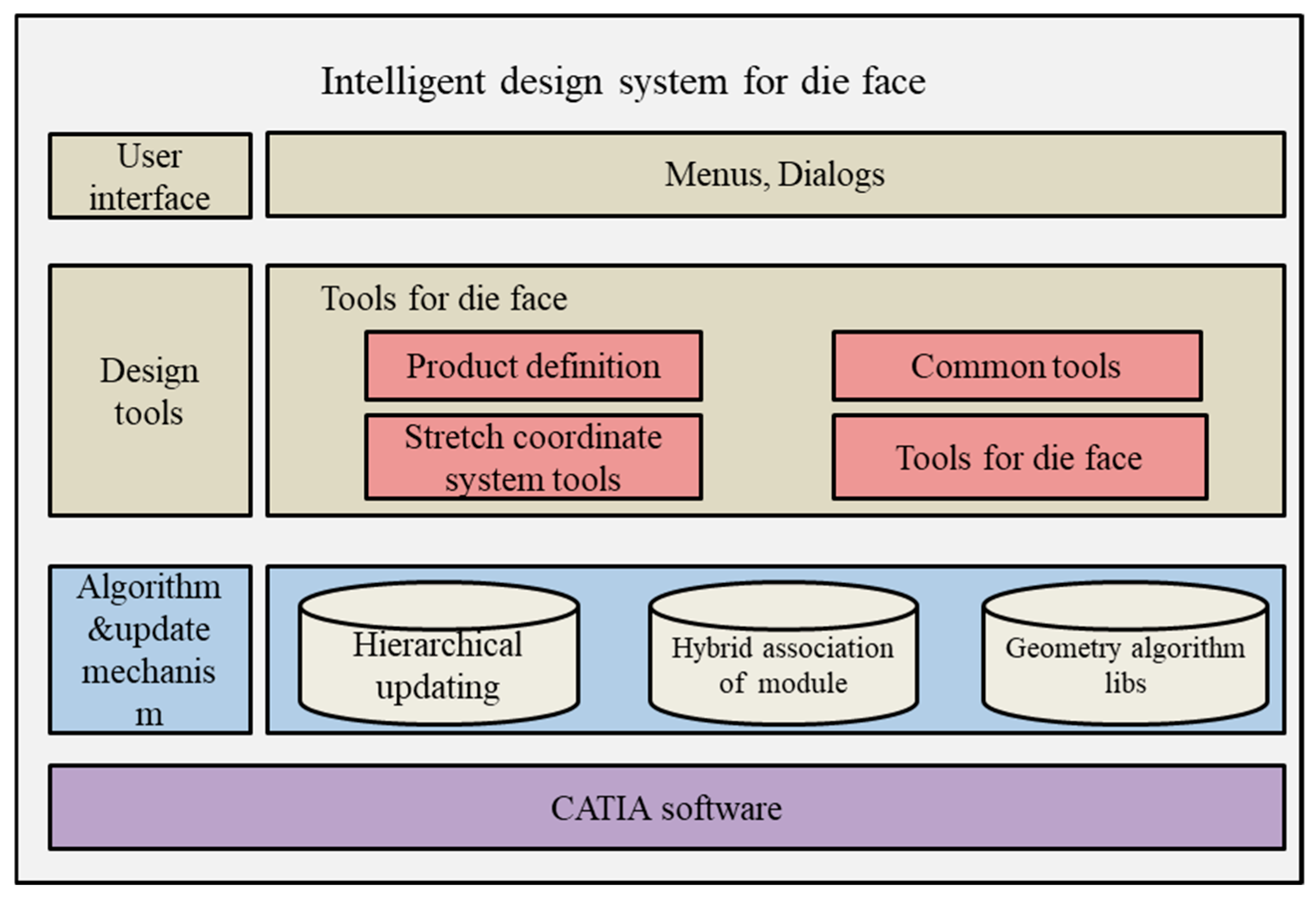
The developed intelligent design system for aircraft die face is based on the CATIA platform. In aircraft die face design and manufacturing processes, CATIA is recognized as one of the most irreplaceable CAD design tools, with powerful surface modeling capabilities. A hierarchical modular architecture integrating platform-independent core algorithms is employed in the system. Porting it to other platforms mainly requires implementing relevant geometric interfaces and conducting customized development of the user interface (UI), thereby enabling seamless cross-platform deployment. The developed intelligent system predominantly leverages the basic surface and curve functionalities and associated application programming interfaces (APIs). Notably, this design paradigm ensures the generated aircraft die surface models achieve consistent and geometrically uniform results across different CATIA software versions, unaffected by variations in software iterations or baseline configurations. As shown in Figure 27, the system architecture of the developed intelligent aircraft skin die face design system is elaborated in detail, composing three hierarchical layers: the Algorithm and Update Mechanism Layer, the Structural Design Tool Layer, and the User Interface Layer.
In the Algorithm and Updating Mechanism Layer, the updating mechanism acts as the basic core for the robustness of the developed intelligent aircraft skin die face design system. The hybrid modular association method ensures the updating stability. Meanwhile, the core geometric algorithms in the system (i.e., stretch coordinate system calculation by ridge curve, boundary filling region recognition, wireframe model method) are critical to the surface quality of aircraft skin die face.
The Structural Design Tool Layer constitutes the core functional component of the developed intelligent aircraft skin die face design system, which consists of four sub-modules: (1) Product preprocessing tools are developed to realize automatic product definition. (2) Stretch coordinate system calculation tools are adopted to achieve automatic product positioning, effectively eliminating critical defects such as negative angles and asymmetric deformations. (3) Tools for die face encompasses hole filling, boundary filling, boundary extension, surrounding side surface design, and filleting design tools. These tools rely on the geometric modeling algorithms to provide a robust, reliable surface generation process. (4) Common tools are a toolset designed for rapid adjustment and evaluation of die face structure, including quick adjustment of stretch coordinate systems and geometric dimensions, negative angle inspection, batch filleting, and other practical functions.
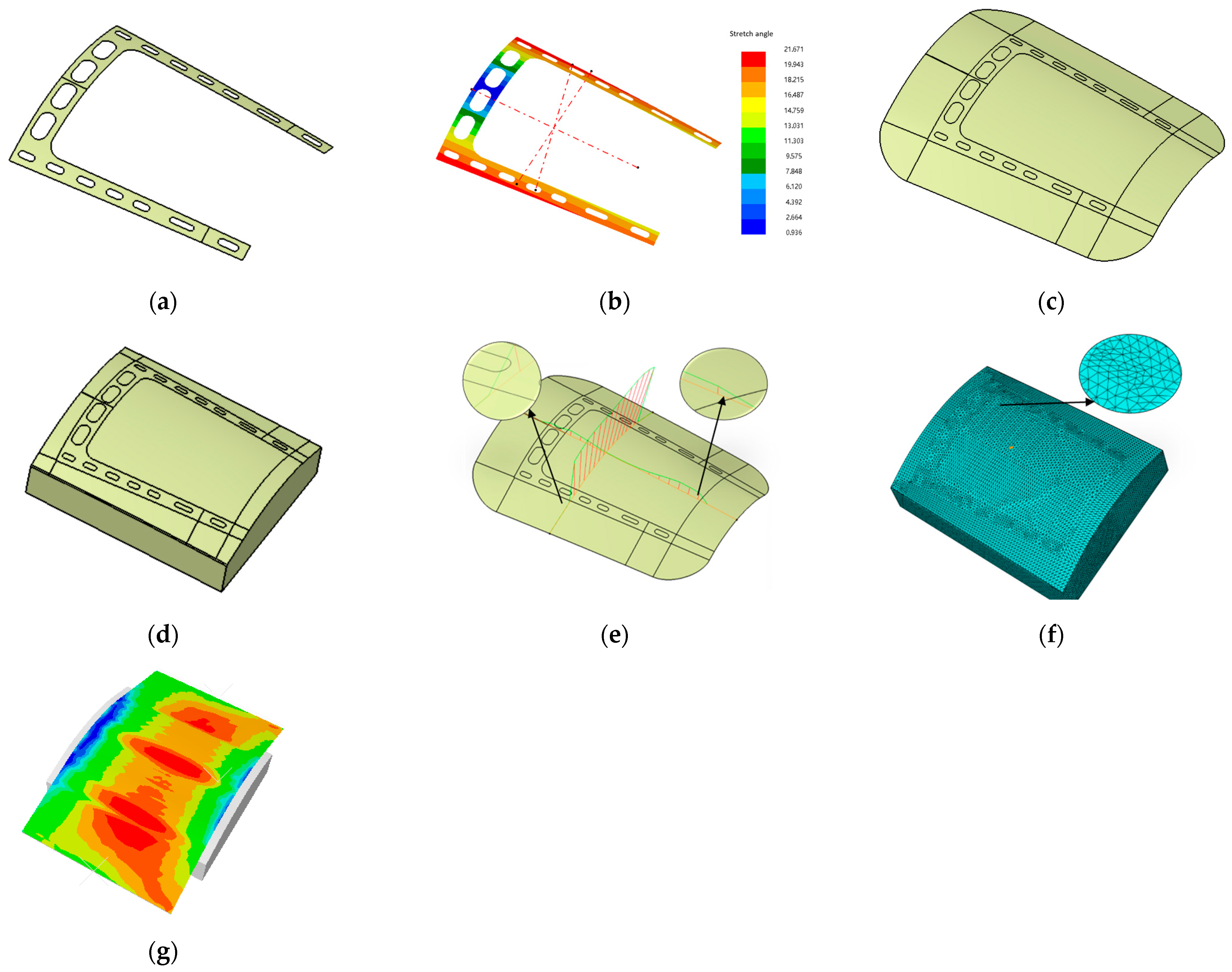
The developed system was applied in two aircraft skin production enterprises in China. To verify the effectiveness and stability of the system, die faces for 23 distinct aircraft skin components were validated in practical production. The system was validated using aircraft skin components 5 m in length, exhibiting stable and reliable operational performance in industrial production enterprise. During the internal systematic testing, dimensional adaptability tests were carried out on aircraft skin components 10 m in length, and the test results indicated that the system was qualified for practical application. The system’s compatibility with the surface complexity of aircraft skin components is achieved by wireframe modeling and other algorithms. Specifically, 23 aircraft skin components were tested and 82.6% of them automatically generated, while the remaining could be completed by minor manual interference adjustment within the system. A typical case of the engineer component is shown in Figure 28, demonstrating the core functions and efficiency of the developed intelligent system.
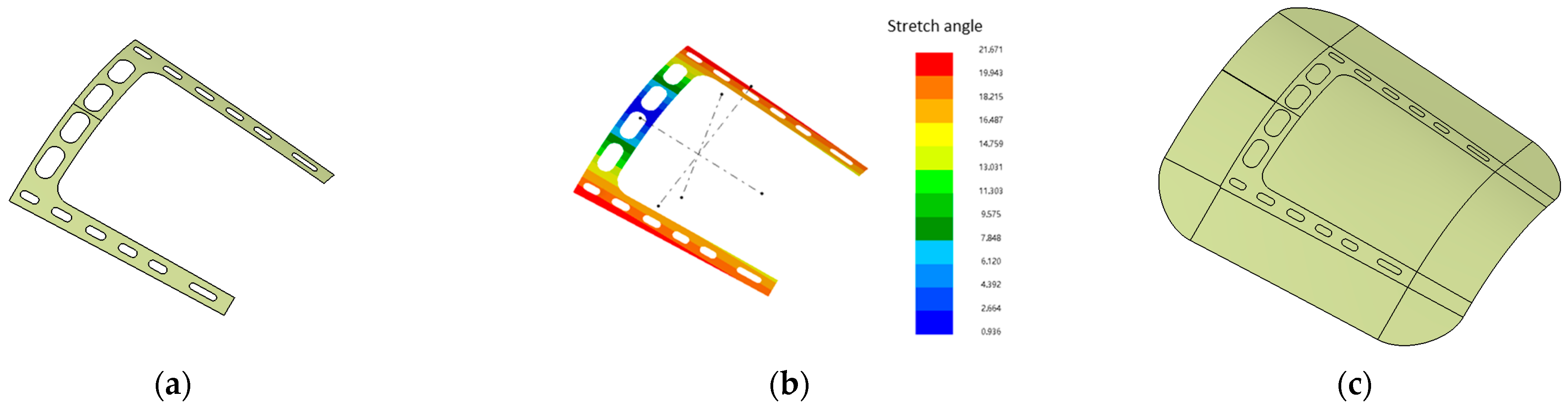
Specifically, Figure 28 illustrates the die surface design results of the developed intelligent system for typical aircraft skin characteristic engineering components. Figure 28a shows the original engineer product. Under the stretch coordinate system generated by the system, no negative angles existed, and the angular distribution was essentially symmetric, as shown in Figure 28b. Figure 28c shows the top die face design results by hole filling, boundary filling, and boundary extending. Figure 28d illustrates the integral die faces of the target engineering aircraft skin component. Through curvature analysis of the aircraft skin die surfaces shown in Figure 28e, it can be observed that the surfaces are predominantly curvature-continuous, without tangent discontinuities. As shown in Figure 28f, high-quality mesh generation is successfully implemented in the establishment of the finite element (FE) model. The FE simulation results are shown in Figure 28g, and the maximum springback value of the aircraft skin component was within 1.5 mm, which falls within the allowable engineering range for aircraft skin stretching forming. Based on sample point measurements of FE simulation results, 85% of the springback values of the sampling points were less than 1.2 mm, which satisfies the design requirements.
Figure 29 shows the updating results of the engineering component die face from the developed intelligent system because of the product iterative design. The engineering component product was revised by reducing both its length and number of holes. The die face of the engineering component automatically updated successfully using the developed system. Specifically, the updating time for the engineering component die face was reduced from 0.5 h to 0.2 h.
The comparative evaluations of design manually on CATIA and automatically by the developed intelligent system are summarized in Table 1 by testing 23 typical aircraft skin components. For design time consumption (hours), the average value of manual design was 1.8 (max/min: 3.1/1.2) versus 0.49 (max/min: 2.1/0.3) for automatic design by the intelligent system, representing an overall efficiency improvement of 72.7%. The aircraft skin die face updating success rate of manual design was 13.0% (3/23), while that of the automatic design using the intelligent system was 52.1% (12/23), representing a 300% improvement. The average manual intervention operations during die face model updating were 7.4 (max/min:13/2) for manual design and 2.2 (max/min: 6/0) for the automatic design using the intelligent system, representing a 70.27% reduction. The die surface C 1 continuity qualification rate reached 91.3% (21/23) for automatic design using the intelligent system and 87.0% (20/23) for manual design, with no significant differences. The aircraft skin components with unsatisfactory C 1 continuity had no impact on mesh generation and finite element (FE) simulation, which still adheres to the system requirements.

5. Conclusions

A dedicated and robust intelligent design system has been developed on the CATIA platform based on the Hierarchical and Hybrid Association Method (HHAM) to realize the automatic design of aircraft skin die face design. In the developed aircraft skin die face design system, the hierarchical updating methodology with a stable error process is the key systematic method in ensuring the robustness of the intelligent system. The hybrid association design of module and feature, which integrates the parameterization of CAD software and automatic re-link relationship, is the base of the HHAM. The core geometric algorithms (i.e., the stretch coordinate system calculation by ridge curve, the automatic filling region recognition, and the wireframe modeling surface generation method) ensures the robustness and quality of generation surfaces for the complex aircraft skin components. The developed system has been applied in two aircraft manufacturing enterprises in China and a large number of different aircraft skin components have been validated. The developed system can improve the design efficiency by 72.7%, which is of great help for aircraft skin component die face design. The automatic and robust iterative design for the revision of stretch forming by the developed system can dramatically shorten the design cycle and reduce costs of repeated revisions of the die face. While the core HHAM proposed in this paper is specifically tailored for the die face design of aircraft skin stretch forming, it cannot be directly applied to other types of die design scenarios. Nevertheless, its core technical methods—including the stable update mechanism and the wireframe modeling method—are applicable to diverse engineering die design fields.
However, in the design process of batch fillets, the fillets may generate failed for some complex aircraft skin components. The future work will focus on the automatic generation of fillets.

Author Contributions

Conceptualization: X.Z. and Z.W.; Methodology: X.Z., Z.W., Y.W. and H.K.; Software: X.Z., Y.W. and H.K.; Formal analysis: H.K., Y.W. and X.Z.; Investigation: H.K. and X.Z.; Data curation: H.K. and X.Z.; Writing—original draft: X.Z.; Writing—review and editing: Z.W., Y.W., Y.L. and Z.Z.; Visualization: Y.W., H.K. and X.Z.; Supervision: Y.L. and Z.Z.; Project administration: H.K. and Y.W.; Funding acquisition: Y.L. and Z.Z. All authors have read and agreed to the published version of the manuscript.

Funding

This work was supported by Foshan Institute of Intelligent Equipment Technology (Grant number 2021B0101220001).

Data Availability Statement

The data presented in this study are available on request from the corresponding author. The data are not publicly available due to privacy reason.

Conflicts of Interest

Authors Haijiao Kong, Zhen Wang and Yang Wei were employed by the Wuhan Huafeng Huizhong Technology Ltd. The remaining authors declare that the research was conducted in the absence of any commercial or financial relationships that could be construed as a potential conflict of interest.

References

  1. Brabie, G.; Lupu, R.; Rizea, A.D.; CărăuȘu, C.; Chicea, A.L.; Maier, C. Review of recent stretch forming development. Proc. Manuf. Syst. 2018, 13, 147–152. [Google Scholar]
  2. Noevere, A.; Wilhite, A. Methodology for lightweight design of stiffened skin in advanced aerospace structures. In Proceedings of the 73rd Annual International Conference on Mass Properties Engineering, Long Beach, CA, USA, 17–22 May 2014. [Google Scholar]
  3. Wang, Z.; Sun, X.; Yang, Y.; Ge, W.; Li, D.; Bao, P.; Da Ronch, A. Design optimization and testing of a morphing leading-edge with a variable-thickness compliant skin and a closed-chain mechanism. Chin. J. Aeronaut. 2024, 37, 285–300. [Google Scholar] [CrossRef] [Scilit]
  4. Ji, L.; Fan, J.; Wan, J.; Yu, G.; Han, W. A hierarchical search-based method for extracting boundary feature lines of aircraft skin. Trans. Can. Soc. Mech. Eng. 2025, 49, 391–405. [Google Scholar] [CrossRef] [Scilit]
  5. Du, J.; Wang, L.; Li, J.; Cui, L.; Jiang, X. The influence of pre-strain levels on the microstructure and performance of aircraft 7b04 aluminium alloy skin. J. Phys. Conf. Ser. 2024, 2691, 012059. [Google Scholar] [CrossRef] [Scilit]
  6. Qi, Z.; Liu, L.; Tian, W.; Wang, P.; Zhang, Z. Prediction of aircraft panel assembly deformation using a combined prediction model. J. Intell. Manuf. 2025, 36, 3761–3781. [Google Scholar] [CrossRef] [Scilit]
  7. Cheng, Y.; Xing, J.; Zhang, B. Research on Stretch Forming Process of the Discrete Clamp for Complex Curved Parts. Mechanika 2022, 28, 5–11. [Google Scholar] [CrossRef] [Scilit]
  8. Jia, B.-B.; Shen, Y.; Gu, Y. Influence of the deformation sequence on the shape accuracy of multi-point forming. Int. J. Mater. Form. Off. J. Eur. Sci. Assoc. Mater. Form.—ESAFORM 2023, 16, 66. [Google Scholar] [CrossRef] [Scilit]
  9. Zhu, J.H.; Gu, X.J.; Zhang, W.H.; Beckers, P. Structural design of aircraft skin stretch-forming die using topology optimization. J. Comput. Appl. Math. 2013, 246, 278–288. [Google Scholar] [CrossRef] [Scilit]
  10. He, D.-h.; Li, D.-s.; Li, X.-q.; Jin, C.h. Optimization on springback reduction in cold stretch forming of titanium-alloy aircraft skin. Trans. Nonferrous Met. Soc. China 2010, 20, 2350–2357. [Google Scholar] [CrossRef] [Scilit]
  11. Michaud, F.; Dalir, H.; Joncas, S. Structural Design and Optimization of an Aircraft Morphing Wing: Composite Skin. J. Aircr. 2018, 55, 195–211. [Google Scholar] [CrossRef] [Scilit]
  12. Song, R.; Chen, Z.; Mayer, R. Blank design for the stretch forming of aircraft skin. In Proceedings of the International Conference on Innovative Design & Manufacturing, Montreal, QC, Canada, 13–15 August 2014; IEEE: New York, NY, USA, 2014. [Google Scholar] [CrossRef] [Scilit]
  13. Wisselink, H.H. Finite Element Simulation of the Stretch-Forming of Aircraft Skins. Am. Inst. Phys. 2005, 778, 60–65. [Google Scholar] [CrossRef] [Scilit]
  14. Sasaki, S.; Kono, A.; Takahashi, S. Improvement in Prediction Accuracy by Finite Element Methods of Stretch-formed Aluminum Alloy Sheets with a Large Aspect Ratio. Procedia Eng. 2014, 81, 927–932. [Google Scholar] [CrossRef] [Scilit]
  15. Zhang, S.; Blala, H.; Su, H.; Cheng, P.; Fu, L. Experimental and numerical investigation of stretch forming process parameters in manufacturing intricate aircraft panels. Int. J. Adv. Manuf. Technol. 2025, 139, 5969–5990. [Google Scholar] [CrossRef] [Scilit]
  16. Laganà, F. Hybrid FEM-AI Approach for Thermographic Monitoring of Biomedical Electronic Devices. Computers 2025, 14, 344. [Google Scholar] [CrossRef] [Scilit]
  17. Liepa, P. Filling Holes in Meshes. In Proceedings of the Eurographics Association, Aachen, Germany, 23–25 June 2003; SGP: New York, NY, USA, 2003. [Google Scholar] [CrossRef]
  18. Shi, K.L.; Yong, J.H.; Sun, J.G.; Paul, J.C.; Gu, H.J. Filling n-sided regions with G1 triangular Coons B-spline patches. Vis. Comput. 2010, 26, 791–800. [Google Scholar] [CrossRef] [Scilit]
  19. Liu, X. Filling n-sided holes with trimmed B-spline surfaces based on energy-minimization method. J. Comput. Inf. Sci. Eng. 2015, 15, 011001. [Google Scholar] [CrossRef] [Scilit]
  20. Shetty, S.; White, P.R. Curvature-continuous extensions for rational B-spline curves and surfaces. Comput.-Aided Des. 1991, 23, 484–491. [Google Scholar] [CrossRef] [Scilit]
  21. Marcheix, D.; Pierra, G. A survey of the persistent naming problem. In Proceedings of the Seventh ACM Symposium on Solid Modeling and Applications, Saarbrücken, Germany, 17–21 June 2002; ACM: New York, NY, USA, 2002. [Google Scholar] [CrossRef] [Scilit]
  22. Ledermann, C.; Hanske, C.; Wenzel, J.; Ermanni, P.; Kelm, R. Associative parametric CAE methods in the aircraft pre-design. Aerospaceence Technol. 2005, 9, 641–651. [Google Scholar] [CrossRef] [Scilit]
  23. Sandberg, M.; Tyapin, I.; Kokkolaras, M.; Lundbladh, A.; Isaksson, O. A knowledge-based master model approach exemplified with jet engine structural design. Comput. Ind. 2017, 85, 31–38. [Google Scholar] [CrossRef] [Scilit]
  24. Dixon, J.R. Knowledge-based systems for design. J. Mech. Des. 1995, 117, 11–16. [Google Scholar] [CrossRef] [Scilit]
  25. Gembarski, P.C. Three ways of integrating computer-aided design and knowledge-based engineering. In Proceedings of the Design Society: DESIGN Conference; Cambridge University Press: Cambridge, UK, 2020; Volume 1, pp. 1255–1264. [Google Scholar] [CrossRef] [Scilit]
  26. Kugler, P.; Dworschak, F.; Schleich, B.; Wartzack, S. The evolution of knowledge-based engineering from a design research perspective: Literature review 2012–2021. Adv. Eng. Inform. 2023, 55, 101892. [Google Scholar] [CrossRef] [Scilit]
  27. Hansen, A.; Arbab, F. An algorithm for generating NC tool paths for arbitrarily shaped pockets with islands. ACM Trans. Graph. 1992, 11, 152–182. [Google Scholar] [CrossRef] [Scilit]
  28. Rohmfeld, R.F. IGB-offset for plane curves-loop removal by scanning of interval sequences. Comput.-Aided Geom. Des. 1998, 15, 339–375. [Google Scholar] [CrossRef] [Scilit]
  29. Maekawa, T. An overview of offset curves and surfaces. Comput.-Aided Des. 1999, 31, 165–173. [Google Scholar] [CrossRef] [Scilit]
  30. Pham, B. Offset curves and surfaces: A brief survey. Comput.-Aided Des. 1992, 24, 223–229. [Google Scholar] [CrossRef] [Scilit]
  31. Tiller, W.; Hanson, E. Offsets of two-dimensional profiles. Comput. Graph. Appl. 1984, 4, 36–46. [Google Scholar] [CrossRef] [Scilit]
  32. Saeed, S.E.O.; Pennington, A.; Dodsworth, J.R. Offsetting in geometric modelling. Comput. Aided Des. 1998, 20, 67–74. [Google Scholar] [CrossRef] [Scilit]
Figure 1. Geometric shape of typical aircraft skin components.
Metals 16 00094 g001
Figure 2. Complex parameterization of aircraft skin die face on CAD software.
Metals 16 00094 g002
Figure 3. Geometric structure of aircraft skin die face.
Metals 16 00094 g003
Figure 4. The design flow of aircraft skin die face.
Metals 16 00094 g004
Figure 5. Stretch coordinate system calculation: (a) stretch coordinate system calculation by minimum bounding box; (b) stretch coordinate system calculation by ridge curve.
Metals 16 00094 g005
Figure 6. Geometric profile of aircraft skin die face.
Metals 16 00094 g006
Figure 7. Geometric parameters of aircraft skin die face surrounding surfaces.
Metals 16 00094 g007
Figure 8. Structure and updating flow of aircraft skin die face module.
Metals 16 00094 g008
Figure 9. Structure and updating flow of aircraft skin die face design geometric features.
Metals 16 00094 g009
Figure 10. Steps of module updating procedure for aircraft skin die face design.
Metals 16 00094 g010
Figure 11. Stable error control process of hierarchical updating flow.
Metals 16 00094 g011
Figure 12. Number of geometric features: (a) Features of origin product; (b) features of revised product.
Metals 16 00094 g012
Figure 13. Topology variation because of product revision: (a) Original product topology; (b) revised product topology.
Metals 16 00094 g013
Figure 14. Hierarchical updating flow of intelligent aircraft skin die face design system.
Metals 16 00094 g014
Figure 15. Geometric wireframe skeleton and node relationship for wireframe model: (a) Wireframe skeleton; (b) tree node relationship.
Metals 16 00094 g015
Figure 16. Geometric generation order of surface patches.
Metals 16 00094 g016
Figure 17. Boundary filling flow.
Metals 16 00094 g017
Figure 18. Boundary filling region recognition algorithm by rolling detection.
Metals 16 00094 g018
Figure 19. Spatial grid acceleration algorithm for rolling detection.
Metals 16 00094 g019
Figure 20. Two types of boundary curves for boundary filling: (a) Directions of boundary filling region; (b) guide curves of boundary filling region.
Metals 16 00094 g020
Figure 21. Interpolation in local coordinates.
Metals 16 00094 g021
Figure 22. Coefficients calculation of interpolation in local coordinates.
Metals 16 00094 g022
Figure 23. Calculation of the basic extension direction.
Metals 16 00094 g023
Figure 24. Edge extending directions: (a) Basic extension direction; (b) directions along minimum curvature.
Metals 16 00094 g024
Figure 25. Segmentation surface of extension wireframe.
Metals 16 00094 g025
Figure 26. Segmentation by control curves self-intersection: (a) Self-intersection region; (b) filling region of self-intersection.
Metals 16 00094 g026
Figure 27. Structure of intelligent aircraft skin die face design system.
Metals 16 00094 g027
Figure 28. Die face design results of engineering aircraft skin component: (a) Engineering aircraft skin component; (b) stretch coordinate system and negative angle detection; (c) top die face surfaces; (d) die face final design results; (e) surface curvature analysis; (f) finite elements meshing result; (g) FE simulation results.
Metals 16 00094 g028
Figure 29. Remodeling die face by intelligent system: (a) Revision aircraft skin component; (b) stretch coordinate system and negative angle detection; (c) top die face; (d) die face final design results; (e) surface curvature analysis; (f) finite meshing result; (g) FE simulation results.
Metals 16 00094 g029aMetals 16 00094 g029b
Table 1. Design efficiency of intelligent system.
Evaluation DataAverage Value of Manual Design by CATIAMax/Min Value of Manual Design by CATIAAverage Value of Automatic Design Using the Intelligent SystemMax/Min Value of Automatic Design Using the Intelligent SystemEfficiency Improvement (%)
Time consumption (hours)1.83.1/1.20.492.1/0.372.7%
Model updating success rate (%)13.0% (3/23)/52.1% (12/23)/300%
Manual intervention times during updating7.413/22.26/070.27%
C 1 continuity qualified rate (%)87.0% (20/23)/91.3% (21/23)/4.7%
FEM qualified rate (%)100%/100%/0%
Disclaimer/Publisher’s Note: The statements, opinions and data contained in all publications are solely those of the individual author(s) and contributor(s) and not of MDPI and/or the editor(s). MDPI and/or the editor(s) disclaim responsibility for any injury to people or property resulting from any ideas, methods, instructions or products referred to in the content.