


Abstract
This study examines the through-thickness microstructure and crystallographic texture evolution in friction-stir-welded (FSWed) AA5052-H32 and AA6061-T651 aluminum alloys using a tri-flats threaded pin tool. Optical microscopy and electron backscatter diffraction (EBSD) were employed to characterize grain morphology, boundary misorientation, and texture components across the weld thickness. Both alloys exhibited progressive grain refinement and increased high-angle grain boundary fractions from the top to the bottom of the stir zone due to combined thermal and strain gradients. The FSWed AA5052 displayed dominant {111}<110> and Y + γ fiber components at the upper and mid regions, whereas AA6061 showed more randomized textures. At the bottom region, both alloys developed rotated Goss {011}<01-1> and weak A ({112}<110>) and α fiber components. These results clarify how alloy strengthening mechanisms—solid-solution versus precipitation hardening—govern texture evolution under different strain-path and heat input conditions. The findings contribute to optimizing process parameters and material selection for structural-scale FSW aluminum joints in industrial applications such as bridge decks, transportation panels, and marine structures.
1. Introduction
Friction stir welding (FSW) is a solid-state welding that exploits the simultaneous application of elevated temperature, forging, and extrusion mechanisms imposed by a rotating tool to join two metallic pieces together. The tool will plastically deform the workpiece by extruding material from the leading side of the tool to the trailing side as it is traversed across the faying interface [1,2]. The unique FSW tool consists of a pin and a shoulder that induces heat and plastic flow through frictional adhesion and subsurface deformation [3,4]. Recent studies demonstrate that material flow during FSW arises from multi-layer shearing and extrusion beneath the tool, producing three-dimensional, evolving strain paths that govern both heat generation and material coalescence [5].
An in-depth metallurgical understanding of the complex material mixing in FSW provides valuable information regarding the process. The plastic flow of the deformed base material can be assessed through observations of local texture evolution of the stir zone [6]. Texture analyses of FSW microstructures have been steadily gaining traction throughout the years, and Table 1 chronologically lists some of the notable works on similar friction stir welding of aluminum alloys.
Table 1.
Crystallographic texture analysis on FSWed aluminum alloys.
Among others, Kumbhar et al. reported that the microstructural evolution in FSWed AA5052 alloy was strongest in the stir zone (SZ) compared to the other weld joint regions [20]. They attributed this observation to the thermal activation through localized frictional heating and heterogeneous plastic deformation. In a microtextural study of AA6063-T5 alloy, Sato et al. reported that the texture on the transverse direction plane exhibits {111} planes parallel to the pin surface (rotation axis) and <110> directions parallel to the transverse direction [6]. Schneider and Nunes also conducted texture analysis on AA2195-T8 and found that the {111} planes are aligned with the tool rotation axis while observing randomly oriented grains in the stir zone (SZ) [12]. In addition, Suhuddin et al. reported the formation of a {112}<110> simple shear texture, which was induced by the rotation of the tool, and observed a well recrystallized grain structure having {100}<100> cube texture in the stir zone [18]. It is well known that the tool profile used in FSW would adversely affect the mechanical and metallurgical characteristics of the stir zone and its periphery. Among others, Ahmed et al. reported the tilt of the <111> pole of the shear texture when a 28.8° tapered tool was utilized in FSW of a 38 mm thick Al plate, while a non-tapered tool resulted in the <111> pole being parallel to the transverse plane [24].
These observations indicate that texture evolution in the stir zone is influenced by the complex deformation field generated beneath the rotating tool, rather than by a single shearing surface. Recent interpretations of FSW flow highlight that a material experiences rotational shear, vertical extrusion, and shear reversal as it circulates around the tool—producing non-monotonic strain paths that collectively determine texture formation [5].
Currently, there is a growing preference for adopting tools with a pin profile that has a tapered, threaded, and tri-flats design. This tool configuration has been reported to enhance material mixing, where the threads promote downward flow, and the flats act as ‘paddles’ to increase the local deformation of plasticized material [37,38,39,40,41,42]. The truncated/tapered pin also offers lower transverse loads, and the largest moment load is at the root of the pin, where it is strongest, enhancing the tool durability [40].
However, as listed in Table 1, the limited studies conducted employing such tool designs mainly focused on a single AA2××× or AA6××× series alloy without any comparative study [13,14,17,23,24,27]. In addition, only a few have systematically examined through-thickness texture evolution using high-resolution EBSD analysis. For example, Das et al. conducted a detailed through-thickness EBSD investigation on a dissimilar multiple-aluminum alloy stack and revealed significant texture gradients and recrystallization behaviors across the weld depth [32]. A recent review by Feddal et al. [43] further emphasizes the need to integrate thickness-resolved texture data to better understand strain and recrystallization mechanisms in these processes.
The present work aims to compare the influence of the tri-flat threaded tool pin design on work-hardened AA5052 aluminum alloys and AA6061 precipitation-hardened alloys to gain a better understanding of how texture morphology differs in these two classes of alloys. Gaining insight into these distinctions will aid in the optimal selection of alloys for welding across diverse industrial applications. The result of the study presents an observable contrast of texture evolution between both alloys after undergoing the FSW process.
2. Materials and Methods
In the present study, 9.5 mm-thick commercially available non-heat-treatable AA5052-H32 (strain-hardened and stress-relieved) and heat-treatable AA6061-T651 (artificially aged) aluminum plates with nominal chemical compositions were used. The 9.5 mm plate thickness was selected to represent structural-scale joints typical of load-bearing aluminum assemblies, such as bridge decks and pedestrian walkways, where friction stir welding has been successfully implemented [44].
The base materials (BM) were friction-stir-welded parallel to the rolling direction. An H13 steel, 8°-tapered, M6-threaded tri-flats tool was utilized. The tool shoulder and pin root diameter were 15 mm and 6 mm, respectively. The pin length was 9.3 mm. A 63 mm/min travel speed and 1120 rpm spindle speed with 2.5° tool tilt towards the welding direction was employed for all FSW processes. The tool rotation was counterclockwise as viewed from above. Welded samples were left to naturally age and stabilized for at least 10 days before any metallurgical work was conducted.
The relatively low traverse speed chosen corresponds to a high heat-input welding condition. This parameter set was constrained by the fixed gear ratio of the available 7.5 HP Jafo FWR40J universal milling machine utilized, which limits the independent control of rotational and traverse speeds. In addition, the combination of large plate thickness and tri-flats pin geometry imposed high mechanical loads on the tool, so higher speeds risked pin failure. As the scope of the present work focuses on microstructural and textural evolution, an extensive study under the same processing conditions on mechanical and process data, including torque, forces, hardness, and heat input, can be found in [45] and [46]. The yield strength, ultimate tensile strength, and elongation for FSWed AA5052 and AA6061 alloys are shown in Table 2 [46].
Table 2.
Yield strength, ultimate tensile strength, and elongation for FSWed 5052-H32 and 6061-T651 (Adapted from Ref. [46]).
The welded samples were cut along the transverse plane for metallographic analysis. Microstructural characterization was conducted based on the standard metallographic procedures, where the cross-sections of the samples were ground, polished, and etched. Keller’s reagent (5 mL HNO3, 3 mL HCl, 2 mL HF, and 190 mL H2O) was used as the etchant, but a modified Poulton’s etch made by mixing two chemical solutions of HNO3(6 mL) + HF(1 mL) + HCl(12 mL) + H2O(1 mL) and H2CrO4(1 g) + HNO3(25 mL) + H2O(10 mL) using a 5–10 s immersion time was also used on AA6061 for better microscopic observations.
The samples were repolished to completely remove the etched surface, and electron backscatter diffraction (EBSD) analysis was conducted using a JEOLJSM-7000F (Tokyo, Japan) equipped with a Schottky field emission gun and a Nordlys II EBSD Camera (Oxford Instruments, High Wycombe, UK) with HKL Channel 5 analysis software to process maps with a 1 µm step size on a 150 × 150 µm grid. Briefly, 15° was set as the boundary differentiating the low-angle grain boundaries (LAGBs) and high-angle grain boundaries (HAGBs). As with common texture connotation, the microtextures will be labeled {hkl}<uvw>, where {hkl} is the crystallographic plane perpendicular to the rolling direction (RD) and <uvw> is the crystallographic direction parallel to the normal direction (ND).
3. Results and Discussion
3.1. Base Materials
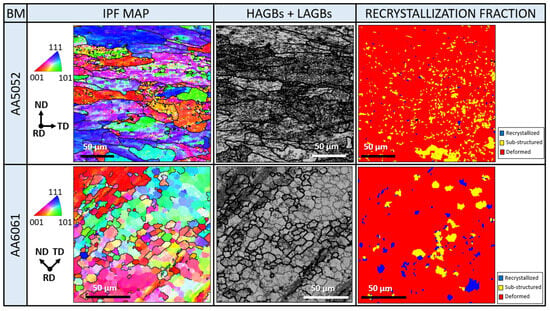
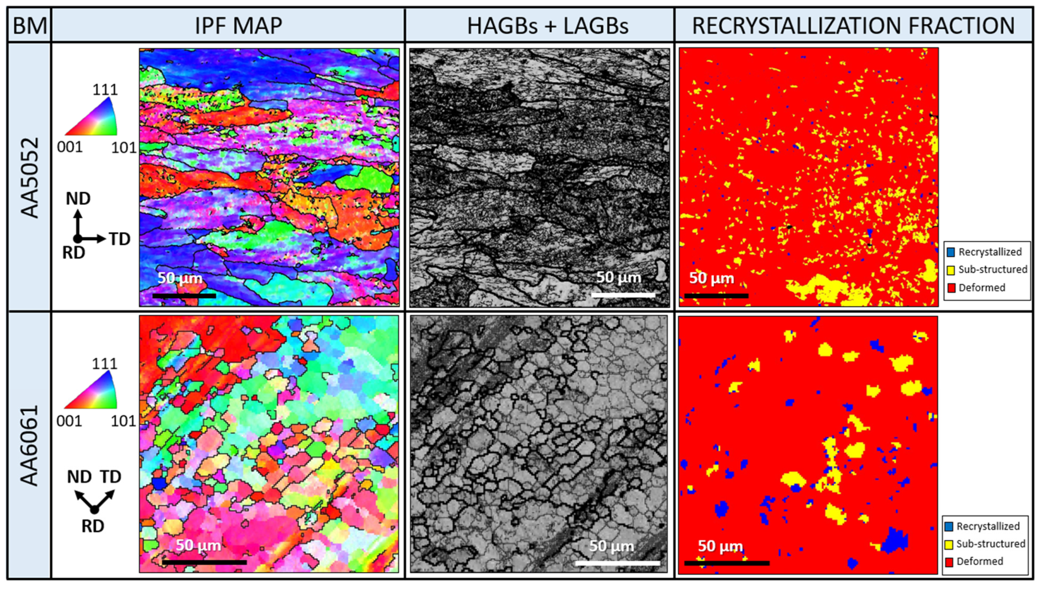
The EBSD analysis was conducted in the mid-thickness region of the base materials. Figure 1 presents the transverse plane inverse pole figures (IPF) mapping of the as-received accompanying HAGBs (thick lines) and LAGBs (thin lines) distribution, as well as the recrystallized fraction of AA5052 and AA6061, respectively. The same color represents the same texture orientation. Henceforth, the reference frame for all the EBSD analysis will be based on the rolling direction (RD), normal direction (ND), and transverse direction (TD). In both samples, the RD is coming out of the paper. In addition, the orientation code triangles represent the standard IPF color mapping to distinguish the three main crystallographic directions in face-centered cubic (FCC) material, such as aluminum alloys, i.e., (001), (101), and (111), shown in red, blue, and green, respectively. These standard color mappings will be used throughout the whole manuscript.
Figure 1.
IPF mapping, distribution of HAGBs and LAGBs, and recrystallized fraction of AA5052 and AA6061 base material.
As shown by the IPF mapping in Figure 1, while both BMs underwent a rolling process, the pancake-shaped grains as a result of the process are more pronounced in AA5052, as evidenced by the high aspect ratio of the grains. The crystallographic texture in AA5052 shows random orientations based on the multiple colors observed, indicating the heterogeneity of the base material. On the other hand, several dominant colors occupying certain regions are visible in AA6061. The AA5052 BM consists of large grains with well-defined HAGBs, while the AA6061 BM seems to show finer grains, as shown in Figure 1. In addition, the AA5052 BM also has a higher density of LAGBs compared to AA6061. However, given that limited color was observed in AA6061 and that the different shades of a similar color are area-specific, it is indicative of large grains with fragmented inner sub-grains separated by low-angle grain boundaries (LAGBs).
Another feature revealed by EBSD analysis is the recrystallization fraction for determining the deformed, recrystallized, and sub-structured grains within a local observed area [47]. From the recrystallization fraction column in Figure 1, both base metals also show a dominant deformed state due to the rolling process [15]. A small portion of the AA6061 also showed recrystallized grains, which are possibly formed during the T6 artificial aging treatment [48].
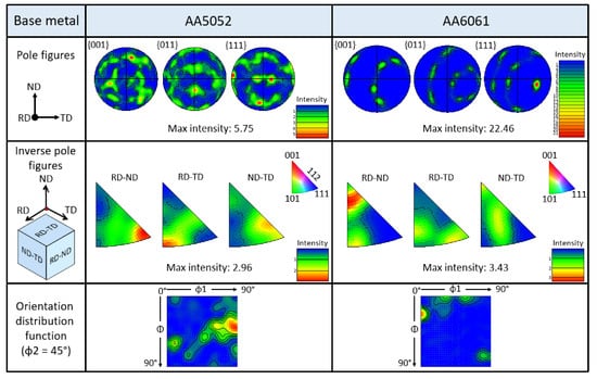
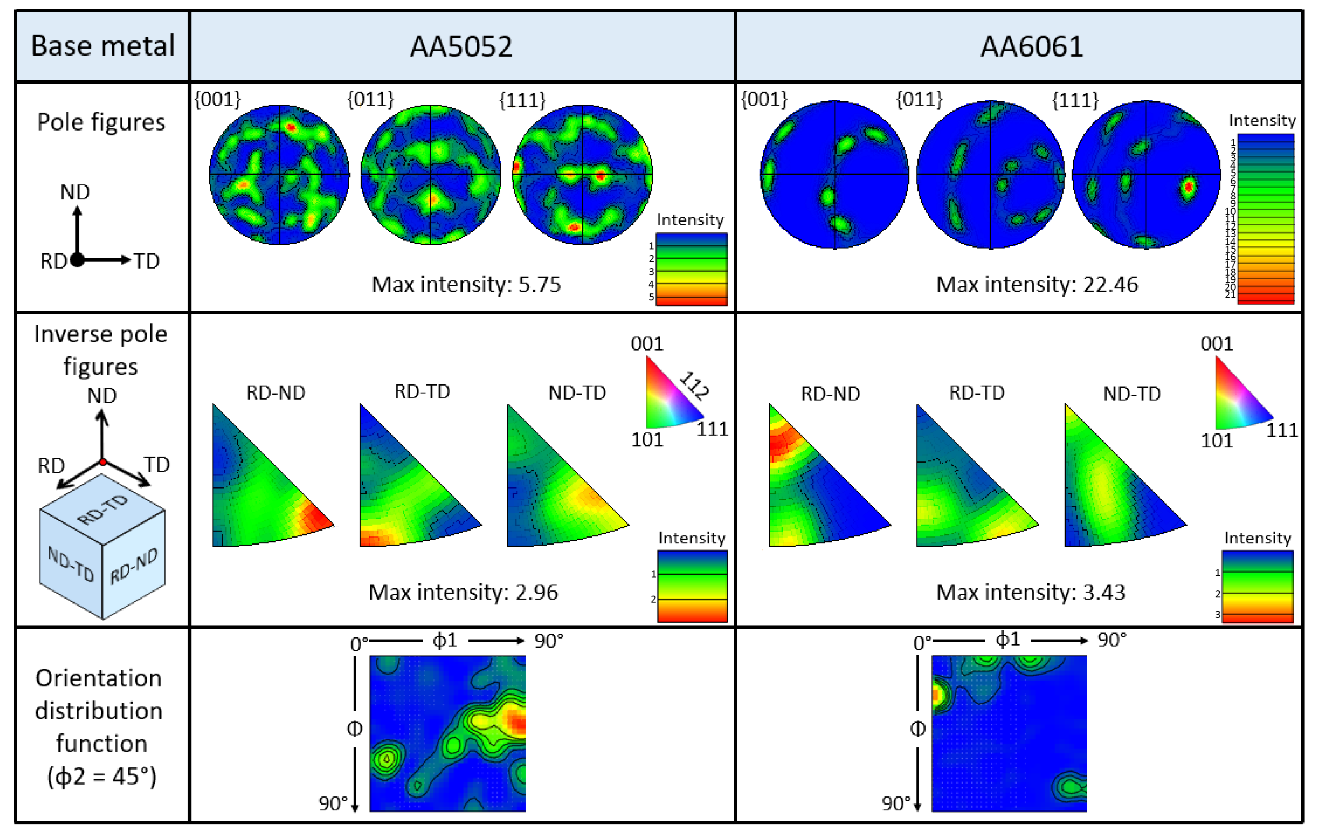
Figure 2 presents the pole figures (PFs), IPFs, and orientation distribution functions (ODFs) based on the 3D-Euler space angles (φ1, Φ, and φ2, where φ2 = 45°) of AA5052 and AA6061 base material, respectively. For the PFs, the axis coming out of the page is the rolling direction, i.e., welding direction for welded specimens, since welding was performed parallel to the rolling direction. For the IPFs, the planes are designated as RD-TD plane (normal plane), ND-TD plane (transverse plane), and RD-ND plane (longitudinal plane).
Figure 2.
Pole figures, IPFs, and ODFs of AA5052 and AA6061 base material.
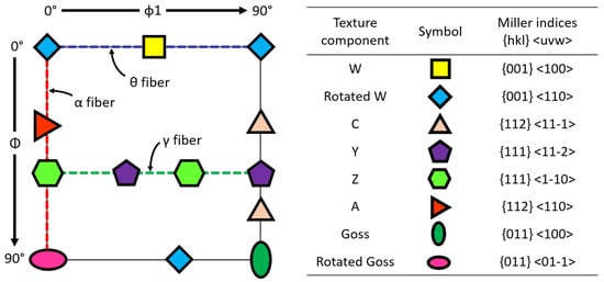
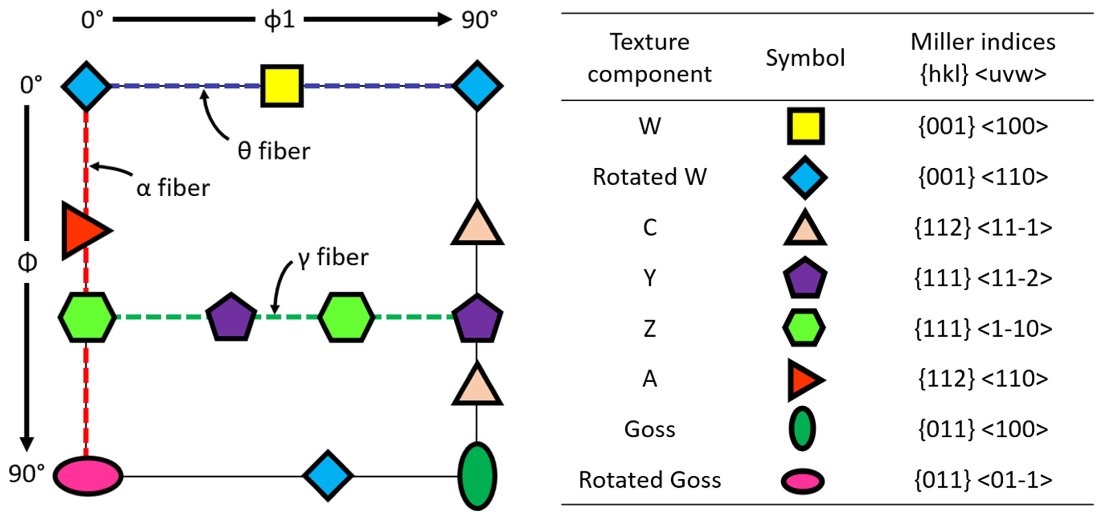
The PFs in Figure 2 further emphasize the randomness of the AA5052 BM texture. In addition, the ODF data were analyzed since the texture component cannot be easily determined through the PFs [18,49]. Figure 3 shows the main ideal texture components of FCC materials based on the Euler angles for the φ2 = 45° section, based on works in [50,51]. A {112}<11-1> or C-texture component was observed for the AA5052 BM.
Figure 3.
Main ideal texture components of FCC materials based on the φ2 = 45° section of the ODF (Adapted from Refs. [50,51]).
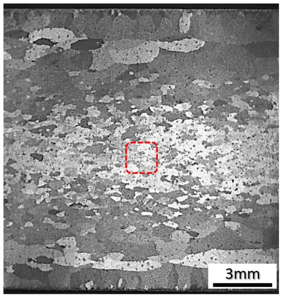
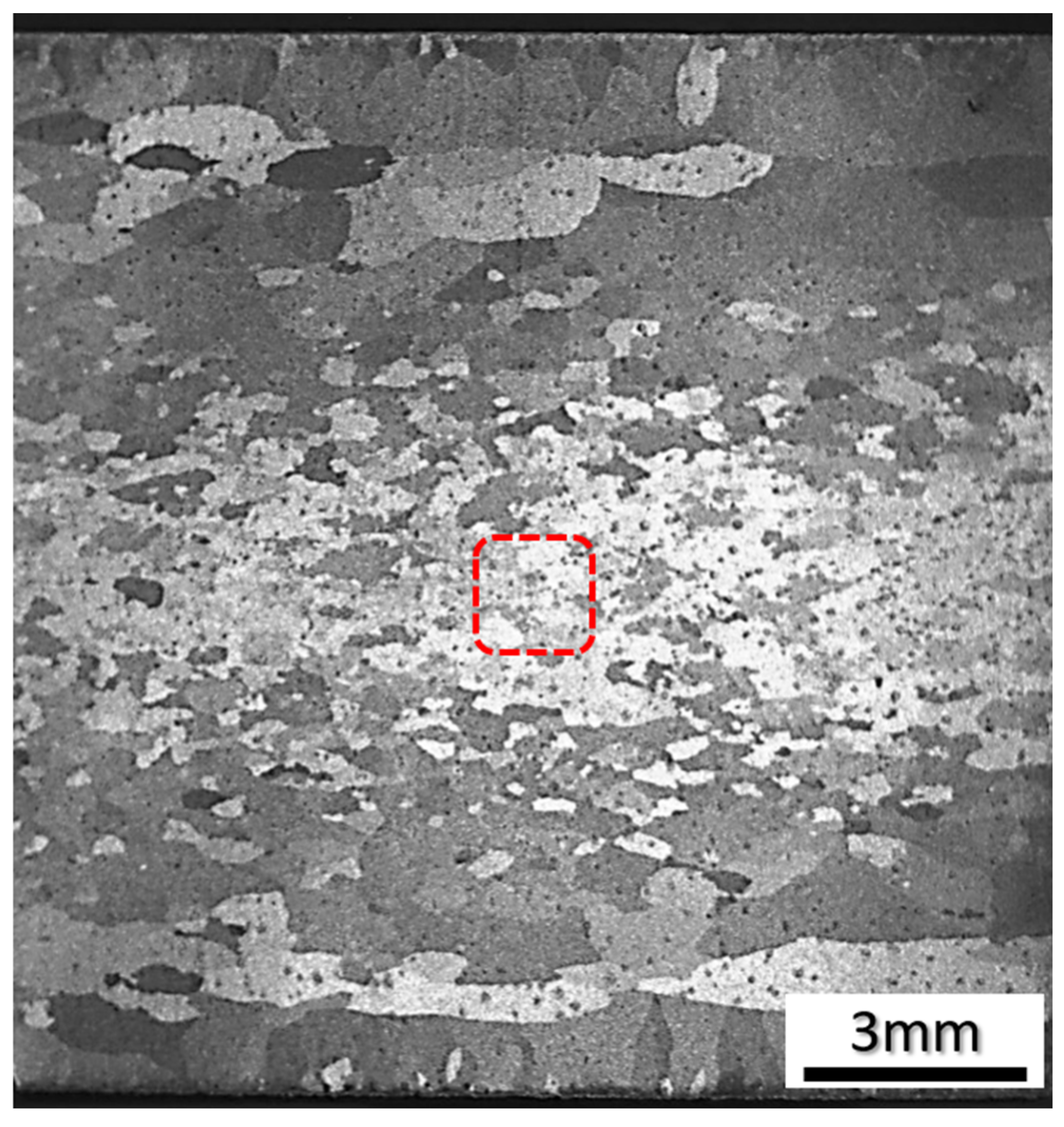
On the other hand, the PF for the AA6061 BM exhibits a highly textured characteristic, as evident by the concentrated {111} PF with a maximum intensity of 22.46, indicative of an alpha fiber texture. The reason for this discrepancy can be attributed to the anomaly in the through-thickness grain size gradient of the as-received base metal, as shown in Figure 4. As the AA6061 alloy underwent cold rolling before the artificial aging treatment, the grains in this region were subjected to extensive deformation. However, during the aging process, only a portion of these grains are recrystallized, forming HAGBs (Figure 1), while the remaining grains with LAGBs, which were possibly part of a large grain, retained their relatively similar crystallographic texture (relatively similar color indexing). Due to the low-fraction HAGB grains-to-area ratio, the EBSD data recorded a highly textured AA6061 base metal, which is slightly misleading. In addition, the texture component for AA6061 also could not be identified from the ODF data, possibly due to the slight tilt of the sample (Figure 2), which may skew the ODF results.
Figure 4.
Transverse plane of AA6061 showing through-thickness grain-size gradient. The red square shows the observed EBSD area.
3.2. Friction-Stir-Welded Samples
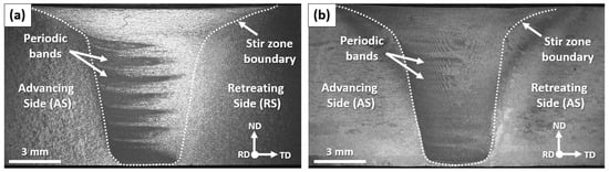
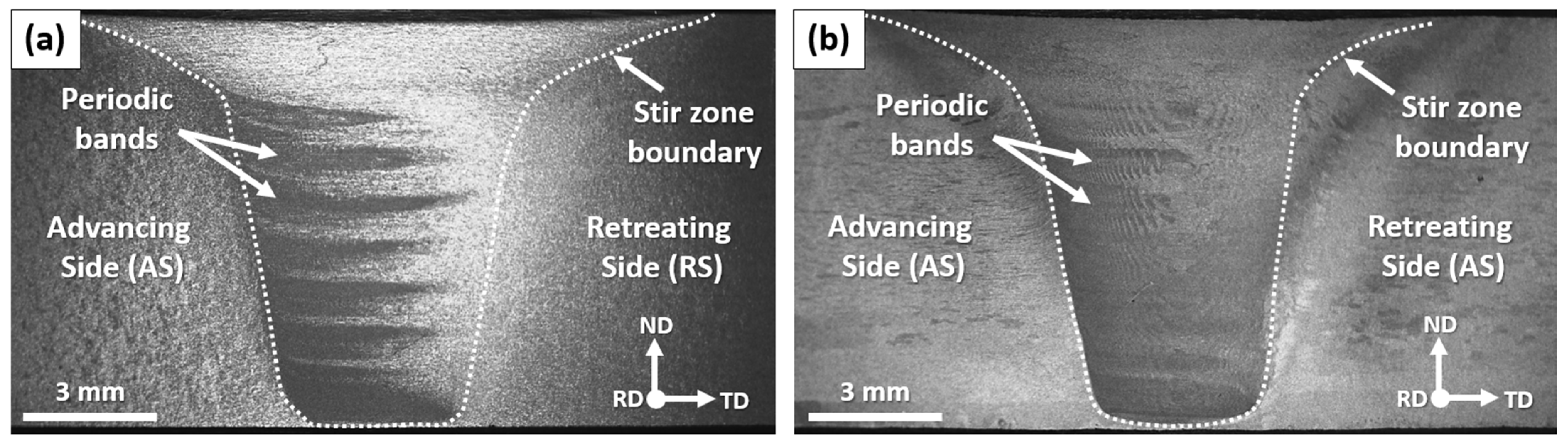
The overall transverse plane micrograph of FSWed AA5052 and AA6061 specimens is shown in Figure 5. The stir zone boundaries are delineated with white dashed lines. The advancing side (AS) and the retreating side (RS) are also denoted, where AS refers to the side where the tangential direction of the rotating tool is similar to the traverse direction, while the RS refers to the side with the tangential direction of the rotation is opposite to the traverse direction, respectively. Notably, one can also note the formation of periodic bands emerging from the AS stir zone boundary of both alloys throughout the through thickness of the stir zone which are formed by the combined effect of the pin’s threaded and tri-flats profile as well as by the difference in the material’s maelstrom (whirlpool) flow in the AS and straight-through flow in the RS, as proposed by Schneider and Nunes [12]. Previous work has established and discussed in length that these bands originated from the advancing side material and therefore will not be repeated here [46]. Due to the strain, strain rate, and temperature gradient throughout the transverse plane of the stir zone, a change in microstructural evolution can be expected [20,52,53,54]. Therefore, several areas in the stir zone region were analyzed.
Figure 5.
The transverse plan micrographs of FSWed (a) AA5052 and (b) AA6061.
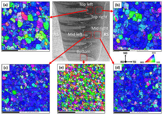
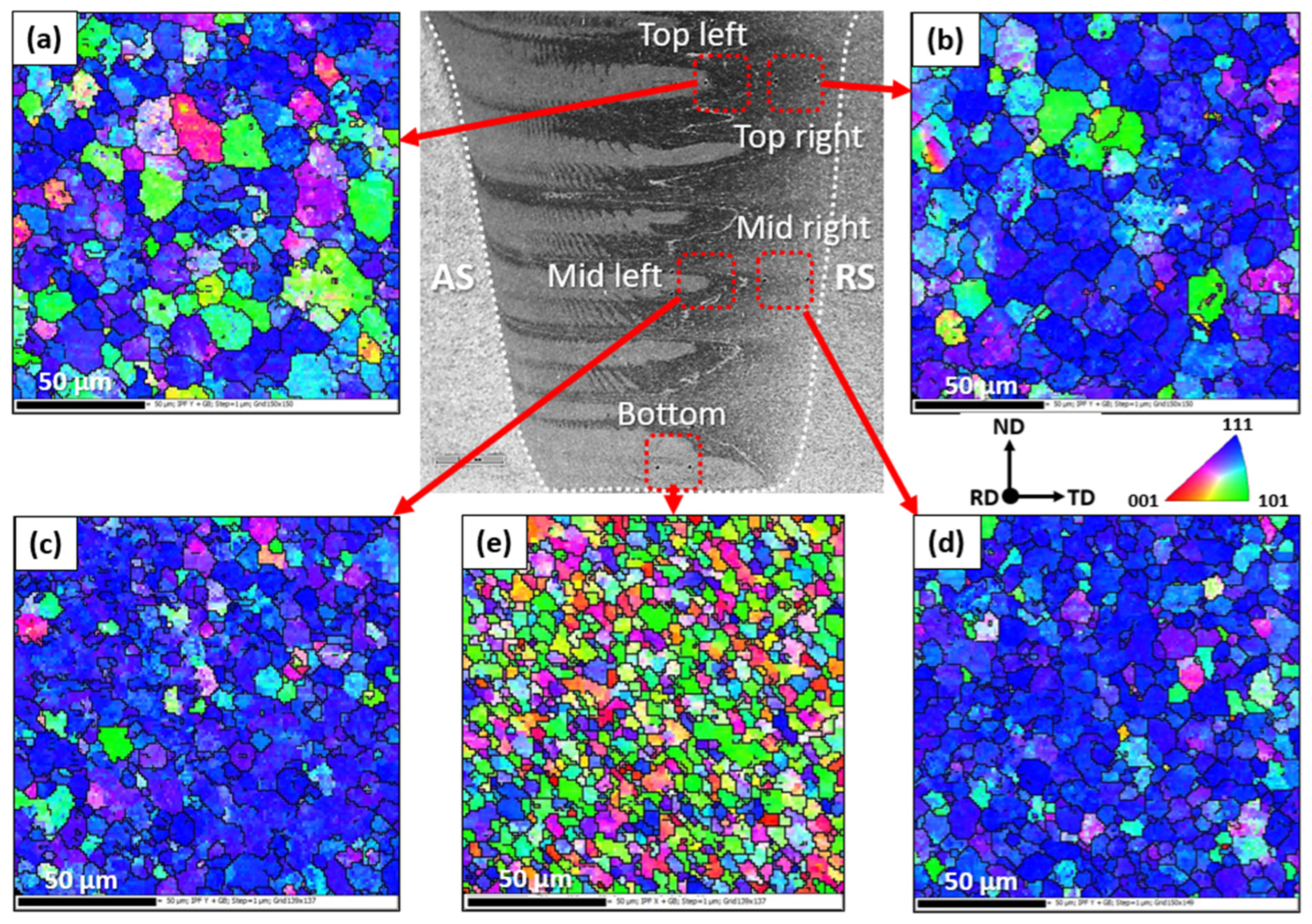
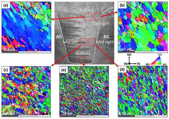
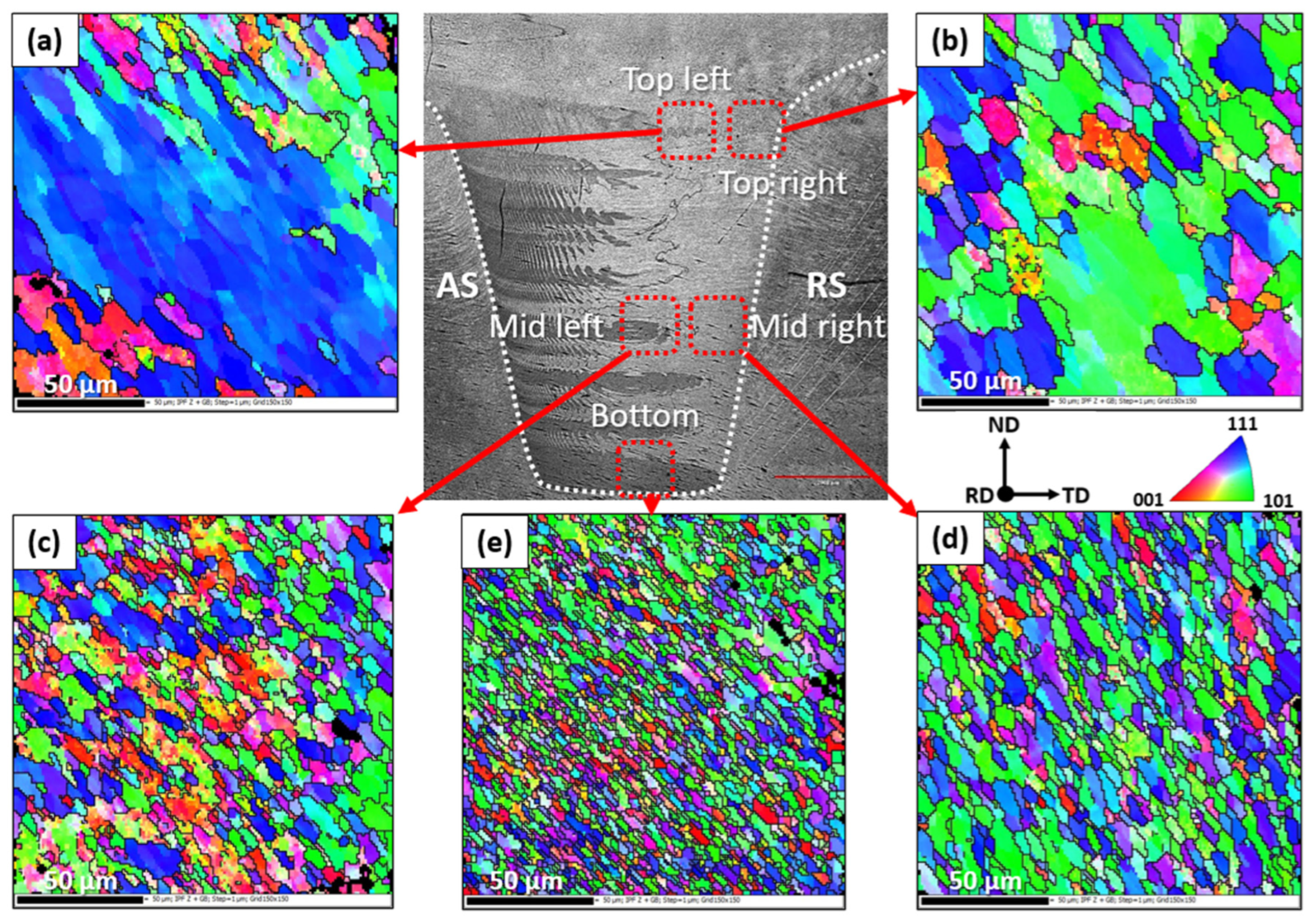
Figure 6 and Figure 7 present the EBSD mapping of various regions in the stir zone of AA5052 and AA6061, respectively. Grain refinement was observed when the area shifted from the top of the stir zone to the bottom of the stir zone. For both samples, the grain size is also relatively similar when comparing the left area (AS material) and right area (RS material) for the top and mid regions. However, the AA5052 sample showed equiaxed grains, while the grains in the AA6061 sample appeared to be more elongated. It seems to suggest that, for the most part, AA6061 underwent geometric dynamic recrystallization (GDRX), which occurs when grains are extremely elongated by severe hot deformation, resulting in impingement of serrated grain boundaries [13].
Figure 6.
Stir zone EBSD mapping of (a) top-left, (b) top-right, (c) mid-left, (d) mid-right, and (e) bottom for AA5052.
Figure 7.
Stir zone EBSD mapping of (a) top-left, (b) top-right, (c) mid-left, (d) mid-right, and (e) bottom for AA6061.
The stir zone in both alloys transformed from relatively large grains with a mixture of LAGBs and HAGBs at the top region towards predominantly fine equiaxed particles surrounded by HAGBs at the bottom area. This can be attributed in part to the absorption of dislocations during the continuous dynamic recrystallization (CDRX), which increases the misorientation of LAGBs, gradually transforming into HAGBs [55,56]. From the Schneider–Nunes kinematic model, which suggested that the material in the maelstrom current undergoes several rotations while experiencing a downward motion before being deposited [12], the bottom region may have also experienced extended shearing, which further refined the grains.
In the AA5052 stir zone, {111} planes were predominantly oriented parallel to the ND-TD plane near the top and mid regions, reflecting shear-dominated flow close to the shoulder. However, rather than representing deformation on a single, tool-defined shear plane, these orientations correspond to the integrated effect of multiple strain paths acting concurrently beneath the tool. Material in the stir zone experiences rotational shear, vertical extrusion, and shear reversal as it circulates around the pin before deposition, producing three-dimensional, non-monotonic strain paths that evolve with depth [5]. The apparent orientation scattering observed at the bottom of the weld therefore reflects the superposition of intersecting strain paths and local strain-rate gradients rather than ‘chaotic’ flow. Similar strain-path-dependent mechanisms, combined with geometric dynamic recrystallization, likely explain the texture randomization observed in AA6061. Differences between the two alloys can also be linked to their respective recovery and precipitation behaviors, which are influenced by local strain-path complexity and time-dependent thermal exposure during cooling [57].
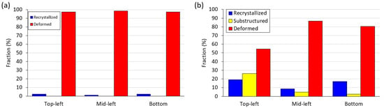
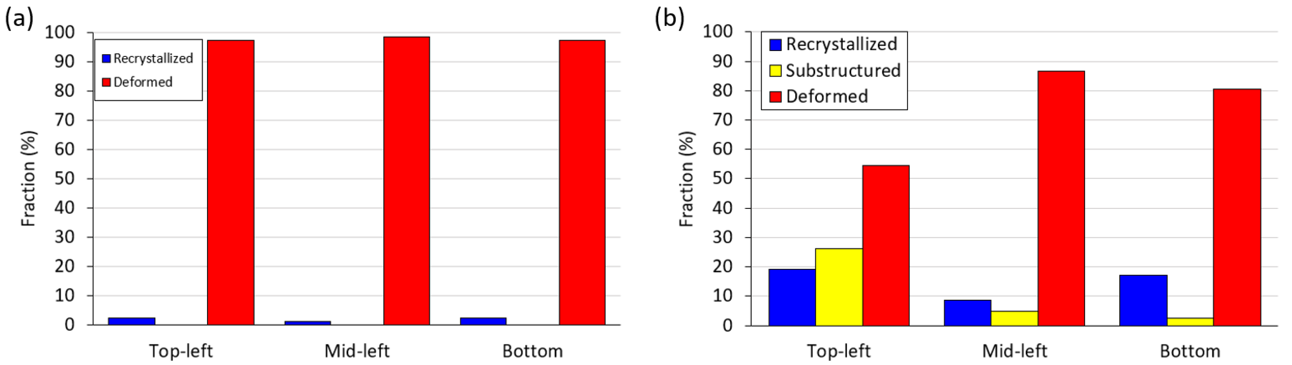
As demonstrated by the recrystallized, sub-structured, and deformed fraction analysis in Figure 8, the stir zone of AA5052 (Figure 8a) consists of deformed grains for all observed regions. However, the stir zone of AA6061 (Figure 8b) indicates that at the top region, a sizable portion of recrystallized and sub-structured grains was also detected. These recrystallized and sub-structured grain fractions significantly decrease as the observed area shifted to the middle and bottom regions.
Figure 8.
Recrystallized, sub-structured, and deformed fractions of (a) AA5052 and (b) AA6061 FSWed regions.
The workpieces underwent thermomechanical changes during FSW, where severe plastic deformation and elevated temperature close to the solidus temperature (Tm) simultaneously occur [45]. It is worth mentioning that the observed microstructure was based on the final structure, where static recovery and recrystallization, as well as grain growth, were expected to occur during the cooling period, which increased the grain size, possibly by HAGB migration [13,53]. The larger grains observed at the top can be postulated to be the result of these physical processes during the cooling period after undergoing dynamic recovery and recrystallization when the tool traversed at the observed plane [58].
Based on previous numerical work by Schmidt et al. [59] with further modifications by Gadakh et al. [60], the percentage of heat generated by the shoulder surface, the tapered pin surface, and the pin tip of the tool used in the current study were calculated to be approximately 71%, 28%, and 1%, respectively. Hence, the majority of the heat generated is concentrated at the top of the stir zone. This heat gradient of thick-plate Al alloys was also proven through metallurgical means by Martinez et al. on AA7449 alloy [61]. The high temperature (0.9 Tm), which well exceeds the recrystallization temperature for both alloys (typically 0.4–0.5 Tm), provides ample time for the dynamically recrystallized grains to grow [13]. In contrast, minimum heat input is generated at the bottom of the weld, and while heat is conductively transferred from the top region, this region mainly undergoes severe plastic deformation, which refines the grains but with minimal grain growth during the cooling period.
It should also be noted that the observed grain-size gradients and partial texture weakening are characteristic of the relatively high heat input associated with the selected low traverse speed. These process conditions, while beneficial for ensuring full penetration and defect-free thick-section joints, may accentuate recovery and recrystallization compared to typical high-speed FSW operations.
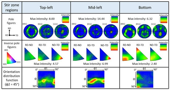
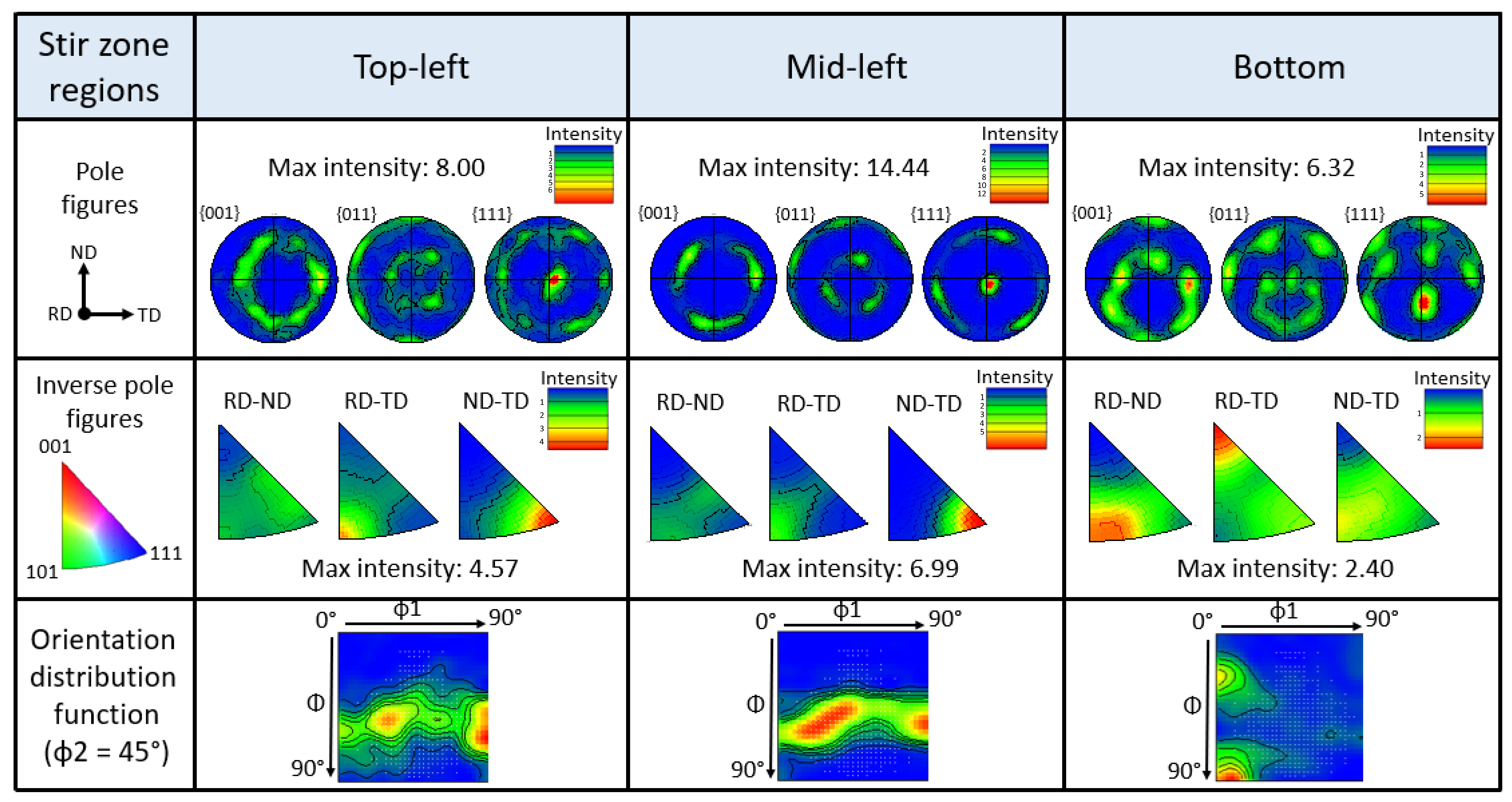
Figure 9 and Figure 10 depict the PFs, IPFs, and ODFs of the AA5052 and AA6061 stir zone regions, respectively. The top-right and mid-right data are omitted due to similarities observed with their respective counterparts. The PFs and the IPFs of the top-left and mid-left of AA5052 show highly textured {111} planes oriented towards the <110> type direction. Based on Figure 3, the ODFs (φ2 = 45°) of the top-left and mid-left regions were found to indicate a {111}<11-2> Y component and γ-fiber texture and a strong rotated Goss {011}<01-1> with a weak {112}<110> A texture component for the bottom region, respectively.
Figure 9.
PFs, IPFs, and ODFs of AA5052 stir zone regions.
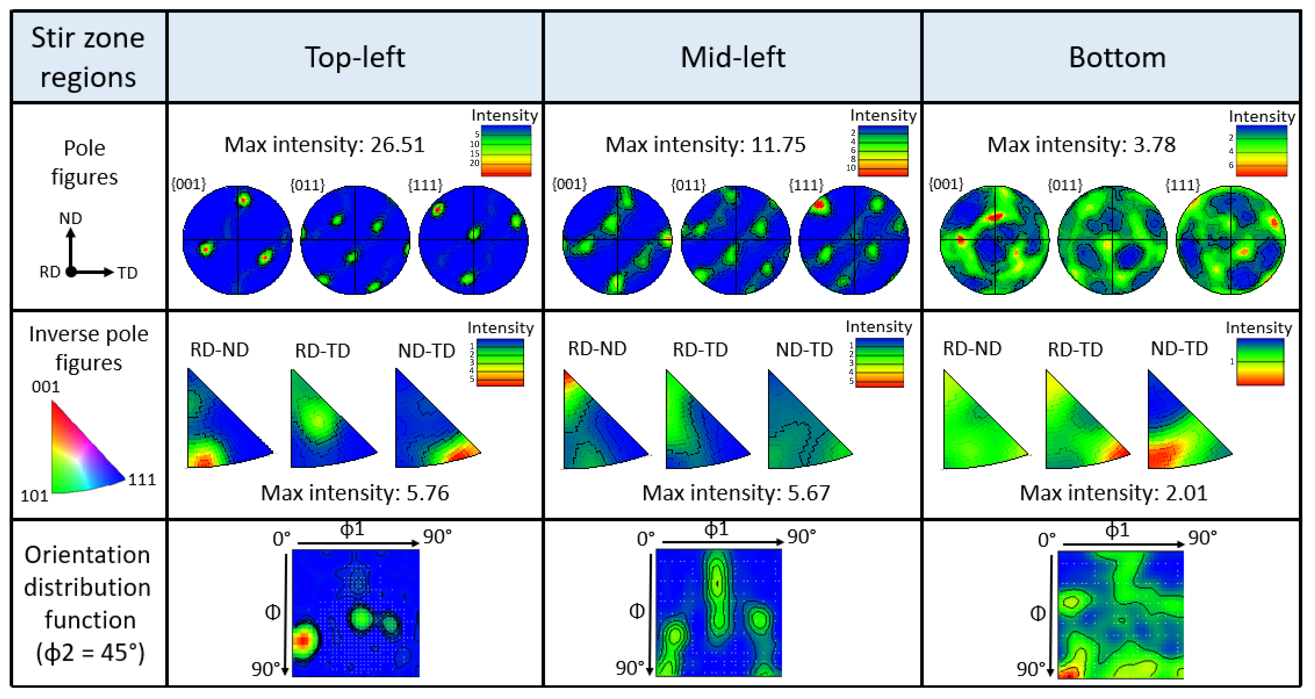
Figure 10.
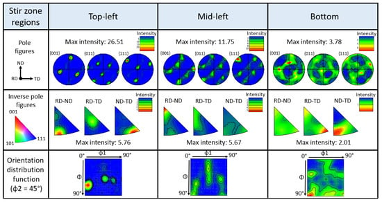
PFs, IPFs, and ODFs of AA6061 stir zone regions.
On the other hand, due to the large grains which contain a considerable amount of LAGB (corresponding to subgrains) as observed in Figure 7a, the top-left region PF of FSWed AA6061 shows a maximum intensity of 26.51. The PF intensity decreases in the mid-left, where the IPF also indicates a relatively high intensity of {001} in the RD-ND plane. For the bottom region, a more random texture is observed, indicated by the respective PF and IPF. From the ODF data, the texture component for the top-left and mid-left could not be identified, but the bottom region shows a mixed rotated Goss texture and an α fiber component. The observed texture and fiber components of the stir zone regions are summarized in Table 3.
Table 3.
Possible texture and fiber components for selected stir zone regions of FSWed AA5052 and AA6061 (Adapted from Ref. [51]).
The above grain size gradient, as well as texture and texture component evolution, demonstrate the heterogeneity of the through-thickness of the stir zone as a result of strain, strain rate, and temperature gradient experienced during FSW [53,62]. The similarities between the results of FSWed AA5052 with previous works seem to suggest that the pin profile generally does not change the shearing mechanism and texture evolution of the stir zone, except for the bottom region, where the complex material flow results in intersecting strain paths [5]. However, the elongated grains and random texture in the AA6061 stir zone seem to show that the pin profile does seem to influence the outcome to a certain degree. Discrepancies between the results obtained in AA5052 and AA6061 stir zones may suggest a difference in material flow behavior induced by the pin profile due to the physical and mechanical properties of each alloy, which may influence the physical processes the alloy experienced during welding.
4. Conclusions
The present study investigated through-thickness microstructure and crystallographic texture evolution in friction-stir-welded AA5052-H32 and AA6061-T651 aluminum alloys using a tri-flats threaded pin tool. The following conclusions were drawn:
- Both alloys exhibited progressive grain refinement and an increased high-angle grain boundary fraction from the top to the bottom of the stir zone, driven by combined thermal and strain gradients.
- The stir zone of AA5052 displayed dominant {111}<110> and Y + γ fiber components at the upper and mid regions, while AA6061 showed more randomized textures.
- At the bottom region, both alloys developed a {011}<01-1> rotated Goss texture component with a weak {112}<110> A texture and α fiber components.
- Differences in textural response between AA5052 and AA6061 arise from their distinct strengthening mechanisms—solid-solution versus precipitation hardening—which influence recovery and recrystallization.
These findings improve understanding of how process parameters and alloy type affect texture evolution in structural-scale friction-stir-welded aluminum joints. Such knowledge supports process optimization and material selection for large-scale applications, including aluminum bridge decks, transportation panels, and marine structures.
Author Contributions
Conceptualization, L.H.A.S. and A.G.; methodology, L.H.A.S. and A.G.; validation, L.H.A.S., A.S. and A.G.; formal analysis, L.H.A.S. and A.S.; investigation, L.H.A.S. and A.S.; resources, S.W. and A.G.; data curation, L.H.A.S. and A.G.; writing—original draft preparation, L.H.A.S.; writing—review and editing, A.S.; visualization, L.H.A.S. and A.S.; supervision, S.W. and A.G.; project administration, S.W. and A.G.; funding acquisition, S.W. and A.G. All authors have read and agreed to the published version of the manuscript.
Funding
This research was funded by the Natural Sciences and Engineering Research Council of Canada (NSERC), the Ministry of Higher Education Malaysia, and Universiti Malaysia Pahang Al-Sultan Abdullah.
Data Availability Statement
The original contributions presented in this study are included in the article. Further inquiries can be directed to the corresponding author.
Acknowledgments
The authors would like to acknowledge the support from the Canadian Centre for Electron Microscopy at McMaster University for the EBSD microscopy analysis, which is supported by NSERC and the Canadian Foundation for Innovation.
Conflicts of Interest
Author Amirali Shamsolhodaei was employed by the company Smarter Alloys. The remaining authors declare that the research was conducted in the absence of any commercial or financial relationships that could be construed as a potential conflict of interest.
References
- Arbegast, W.J. A Flow-Partitioned Deformation Zone Model for Defect Formation during Friction Stir Welding. Scr. Mater. 2008, 58, 372–376. [Google Scholar] [CrossRef] [Scilit]
- Nandan, R.; DebRoy, T.; Bhadeshia, H. Recent Advances in Friction-Stir Welding–Process, Weldment Structure and Properties. Prog. Mater. Sci. 2008, 53, 980–1023. [Google Scholar] [CrossRef] [Scilit]
- Qiang, F.; Xin, S.; Yang, X.S.; Wang, H.; Guo, P.; Hou, H.; Lian, Z.; Zhang, L.; Hou, W. Low-Temperature Superplastic Deformation Mechanism of Ultra-Fine Grain Ti–6Al–4V Alloy by Friction Stir Processing. J. Mater. Res. Technol. 2024, 30, 7413–7419. [Google Scholar] [CrossRef] [Scilit]
- Mishra, R.S.; Ma, d.Z. Friction Stir Welding and Processing. Mater. Sci. Eng. R Rep. 2005, 50, 1–78. [Google Scholar] [CrossRef] [Scilit]
- Hoßfeld, M. On Friction, Heat Input, and Material Flow Initiation during Friction Stir Welding: Tool and Process Optimization. J. Manuf. Mater. Process. 2023, 7, 34. [Google Scholar] [CrossRef] [Scilit]
- Sato, Y.S.; Kokawa, H.; Ikeda, K.; Enomoto, M.; Hashimoto, T.; Jogan, S. Microtexture in the Friction-Stir Weld of an Aluminum Alloy. Metall. Mater. Trans. A 2001, 32, 941–948. [Google Scholar] [CrossRef] [Scilit]
- Field, D.P.; Nelson, T.W.; Hovanski, Y.; Jata, K.V. Heterogeneity of Crystallographic Texture in Friction Stir Welds of Aluminum. Metall. Mater. Trans. A 2001, 32, 2869–2877. [Google Scholar] [CrossRef] [Scilit]
- Jin, H.; Saimoto, S.; Ball, M.; Threadgill, P. Characterisation of Microstructure and Texture in Friction Stir Welded Joints of 5754 and 5182 Aluminium Alloy Sheets. Mater. Sci. Technol. 2001, 17, 1605–1614. [Google Scholar] [CrossRef] [Scilit]
- Heinz, B.; Skrotzki, B. Characterization of a Friction-Stir-Welded Aluminum Alloy 6013. Metall. Mater. Trans. B 2002, 33, 489–498. [Google Scholar] [CrossRef] [Scilit]
- Fonda, R.; Bingert, J. Microstructural Evolution in the Heat-Affected Zone of a Friction Stir Weld. Metall. Mater. Trans. A 2004, 35, 1487–1499. [Google Scholar] [CrossRef] [Scilit]
- Fonda, R.; Bingert, J.; Colligan, K. Development of Grain Structure during Friction Stir Welding. Scr. Mater. 2004, 51, 243–248. [Google Scholar] [CrossRef]
- Schneider, J.; Nunes, A., Jr. Characterization of Plastic Flow and Resulting Microtextures in a Friction Stir Weld. Metall. Mater. Trans. B 2004, 35, 777–783. [Google Scholar] [CrossRef] [Scilit]
- Prangnell, P.; Heason, C. Grain Structure Formation during Friction Stir Welding Observed by the ‘Stop Action Technique.’. Acta Mater. 2005, 53, 3179–3192. [Google Scholar] [CrossRef] [Scilit]
- Fonda, R.; Bingert, J. Precipitation and Grain Refinement in a 2195 Al Friction Stir Weld. Metall. Mater. Trans. A 2006, 37, 3593–3604. [Google Scholar] [CrossRef] [Scilit]
- Etter, A.; Baudin, T.; Fredj, N.; Penelle, R. Recrystallization Mechanisms in 5251 H14 and 5251 O Aluminum Friction Stir Welds. Mater. Sci. Eng. A 2007, 445, 94–99. [Google Scholar] [CrossRef] [Scilit]
- McNelley, T.; Swaminathan, S.; Su, J. Recrystallization Mechanisms during Friction Stir Welding/Processing of Aluminum Alloys. Scr. Mater. 2008, 58, 349–354. [Google Scholar] [CrossRef] [Scilit]
- Ahmed, M.; Wynne, B.; Rainforth, W.; Threadgill, P. Quantifying Crystallographic Texture in the Probe-Dominated Region of Thick-Section Friction-Stir-Welded Aluminium. Scr. Mater. 2008, 59, 507–510. [Google Scholar] [CrossRef] [Scilit]
- Suhuddin, U.; Mironov, S.; Sato, Y.; Kokawa, H. Grain Structure and Texture Evolution during Friction Stir Welding of Thin 6016 Aluminum Alloy Sheets. Mater. Sci. Eng. A 2010, 527, 1962–1969. [Google Scholar] [CrossRef] [Scilit]
- Guo, J.; Amira, S.; Gougeon, P.; Chen, X.-G. Effect of the Surface Preparation Techniques on the EBSD Analysis of a Friction Stir Welded AA1100-B4C Metal Matrix Composite. Mater. Charact. 2011, 62, 865–877. [Google Scholar] [CrossRef] [Scilit]
- Kumbhar, N.; Sahoo, S.; Samajdar, I.; Dey, G.; Bhanumurthy, K. Microstructure and Microtextural Studies of Friction Stir Welded Aluminium Alloy 5052. Mater. Des. 2011, 32, 1657–1666. [Google Scholar] [CrossRef] [Scilit]
- Cho, J.-H.; Kim, W.J.; Lee, C.G. Texture and Microstructure Evolution and Mechanical Properties during Friction Stir Welding of Extruded Aluminum Billets. Mater. Sci. Eng. A 2014, 597, 314–323. [Google Scholar] [CrossRef] [Scilit]
- Wang, T.; Zou, Y.; Matsuda, K. Micro-Structure and Micro-Textural Studies of Friction Stir Welded AA6061-T6 Subjected to Different Rotation Speeds. Mater. Des. 2016, 90, 13–21. [Google Scholar] [CrossRef] [Scilit]
- Fonda, R.; Rowenhorst, D.; Knipling, K. 3D Material Flow in Friction Stir Welds. Metall. Mater. Trans. A 2019, 50, 655–663. [Google Scholar] [CrossRef] [Scilit]
- Ahmed, M.; Wynne, B.; Rainforth, W.; Addison, A.; Martin, J.; Threadgill, P. Effect of Tool Geometry and Heat Input on the Hardness, Grain Structure, and Crystallographic Texture of Thick-Section Friction Stir-Welded Aluminium. Metall. Mater. Trans. A 2019, 50, 271–284. [Google Scholar] [CrossRef] [Scilit]
- Kalinenko, A.; Vysotskii, I.; Malopheyev, S.; Mironov, S.; Kaibyshev, R. Relationship between Welding Conditions, Abnormal Grain Growth and Mechanical Performance in Friction-Stir Welded 6061-T6 Aluminum Alloy. Mater. Sci. Eng. A 2021, 817, 141409. [Google Scholar] [CrossRef] [Scilit]
- Hou, W.; Ding, Y.; Huang, G.; Huda, N.; Shah, L.H.A.; Piao, Z.; Shen, Y.; Shen, Z.; Gerlich, A. The Role of Pin Eccentricity in Friction Stir Welding of Al-Mg-Si Alloy Sheets: Microstructural Evolution and Mechanical Properties. Int. J. Adv. Manuf. Technol. 2022, 121, 7661–7675. [Google Scholar] [CrossRef] [Scilit]
- Shah, L.H.A.; Hou, W.; Razmpoosh, M.H.; Walbridge, S.; Gerlich, A. Strain Rate and Microtexture Analysis of Rapid-Quenched AA6061 Friction Stir Welds Produced with Tool Eccentricity. J. Mater. Res. Technol. 2022, 21, 1434–1441. [Google Scholar] [CrossRef] [Scilit]
- Liu, X.; Ye, T.; Li, Y.; Pei, X.; Sun, Z. Quasi-in-Situ Characterization of Microstructure Evolution in Friction Stir Welding of Aluminum Alloy. J. Mater. Res. Technol. 2023, 25, 6380–6394. [Google Scholar] [CrossRef] [Scilit]
- Luo, Z.; Sun, Y.; Li, W.; He, J.; Luo, G.; Liu, H. Evolution of Microstructures, Texture and Mechanical Properties of Al-Mg-Si-Cu Alloy under Different Welding Speeds during Friction Stir Welding. Metals 2023, 13, 1120. [Google Scholar] [CrossRef] [Scilit]
- Ahmed, M.M.; Essa, A.R.; Ataya, S.; El-Sayed Seleman, M.M.; El-Aty, A.A.; Alzahrani, B.; Touileb, K.; Bakkar, A.; Ponnore, J.J.; Mohamed, A.Y. Friction Stir Welding of AA5754-H24: Impact of Tool Pin Eccentricity and Welding Speed on Grain Structure, Crystallographic Texture, and Mechanical Properties. Materials 2023, 16, 2031. [Google Scholar] [CrossRef] [Scilit]
- Sundar, A.S.; Kar, A.; Mugada, K.K.; Kumar, A. Enhancement of Microstructure, Micro-Texture, and Mechanical Properties of Al6061 Friction Stir Welds Using the Developed Static Shoulder Welding Tool. Mater. Charact. 2023, 203, 113148. [Google Scholar] [CrossRef] [Scilit]
- Das, H.; Kalsar, R.; Shukla, S.; Anaman, S.Y.; Upadhyay, P.; Cho, H. Microstructure and Texture Evolution of Friction Stir Lap Welded Dissimilar Multi-aluminum Stack. Mater. Charact. 2023, 206, 113398. [Google Scholar] [CrossRef] [Scilit]
- Li, W.; Luo, Z.; Sun, Y.; Liu, X. Effect of Tool Speed on Microstructure Evolution and Mechanical Properties of Friction Stir Welded Joints of Al-Mg-Si Alloy with High Cu Content. Metals 2024, 14, 758. [Google Scholar] [CrossRef] [Scilit]
- Naseri, M.; Alvand, M.; Ahmadi, E.; Hosseini, S.; Gholami, D.; Mourad, A.-H.I.; Borhani, E. Effect of Cube Texture on Local Softening of Friction Stir Welded Joints for Nanostructured AA2024 Processed by Accumulative Roll Bonding. J. Mater. Res. Technol. 2024, 28, 3507–3513. [Google Scholar] [CrossRef] [Scilit]
- Kim, J.-H.; Choi, H.-N.; Lee, K.-J.; Shin, J.; Seo, N.; Jung, J.-G.; Lee, S.-J.; Lee, S.-J. Effect of Welding Speed on Microstructural Evolution and Strengthening Mechanism of Friction-Stir Welded 7075 Aluminum. Mater. Sci. Eng. A 2024, 908, 146695. [Google Scholar] [CrossRef] [Scilit]
- Kesharwani, R.; Jha, K.K.; Imam, M.; Sarkar, C.; Barsoum, I. Correlation of Microstructure, Texture, and Mechanical Properties of Friction Stir Welded Joints of AA7075-T6 Plates Using a Flat Tool Pin Profile. Heliyon 2024, 10, e25449. [Google Scholar] [CrossRef] [Scilit]
- Elangovan, K.; Balasubramanian, V. Influences of Pin Profile and Rotational Speed of the Tool on the Formation of Friction Stir Processing Zone in AA2219 Aluminium Alloy. Mater. Sci. Eng. A 2007, 459, 7–18. [Google Scholar] [CrossRef] [Scilit]
- Zhang, Y.; Cao, X.; Larose, S.; Wanjara, P. Review of Tools for Friction Stir Welding and Processing. Can. Metall. Q. 2012, 51, 250–261. [Google Scholar] [CrossRef] [Scilit]
- Rai, R.; De, A.; Bhadeshia, H.; DebRoy, T. Friction Stir Welding Tools. Sci. Technol. Weld. Join. 2011, 16, 325. [Google Scholar] [CrossRef] [Scilit]
- Fuller, C.B. Friction Stir Tooling: Tool Materials and Designs. In Friction Stir Welding and Processing; ASM International: Materials Park, OH, USA, 2007; Volume 7. [Google Scholar]
- Shah, L.; Walbridge, S.; Gerlich, A. Tool Eccentricity in Friction Stir Welding: A Comprehensive Review. Sci. Technol. Weld. Join. 2019, 24, 566–578. [Google Scholar] [CrossRef] [Scilit]
- Reza-E-Rabby, M.; Tang, W.; Reynolds, A.P. Effects of Thread Interruptions on Tool Pins in Friction Stir Welding of AA6061. Sci. Technol. Weld. Join. 2018, 23, 114–124. [Google Scholar] [CrossRef] [Scilit]
- Feddal, I.; Chairi, M.; Bella, G.D. Analysis of Friction Stir Welding of Aluminum Alloys. Metals 2025, 15, 532. [Google Scholar] [CrossRef] [Scilit]
- Vigh, L.G.; Schnierer, G.; Buchmüller, J.; Pohl, Á.; Turányi, B.; Kiss, L.I.; St-Georges, L.; Dussault, L. Conceptual Design of an Aluminium Bridge in Alma, QC. Key Eng. Mater. 2016, 710, 383–389. [Google Scholar] [CrossRef] [Scilit]
- Shah, L.H.; Fleury, A.; St-George, L.; Walbridge, S.; Gerlich, A.P. Evolution of Process Parameters in Friction Stir Welding of AA6061 Aluminum Alloy by Varying Tool Eccentricity. Int. J. Adv. Manuf. Technol. 2020, 109, 1601–1612. [Google Scholar] [CrossRef] [Scilit]
- Shah, L.H.; Sonbolestan, S.E.; Midawi, A.R.H.; Walbridge, S.; Gerlich, A.P. Dissimilar Friction Stir Welding of Thick Plate AA5052-AA6061 Aluminum Alloys: Effects of Material Positioning and Tool Eccentricity. Int. J. Adv. Manuf. Technol. 2019, 105, 889–904. [Google Scholar] [CrossRef] [Scilit]
- Black, M.; Higginson, R. An Investigation into the Use of Electron Back Scattered Diffraction to Measure Recrystallised Fraction. Scr. Mater. 1999, 41, 125–129. [Google Scholar] [CrossRef] [Scilit]
- Handbook, A. Heat Treating of Aluminum Alloys. ASM Int. 1991, 4, 1862. [Google Scholar]
- Li, S.; Beyerlein, I.J.; Bourke, M.A. Texture Formation during Equal Channel Angular Extrusion of Fcc and Bcc Materials: Comparison with Simple Shear. Mater. Sci. Eng. A 2005, 394, 66–77. [Google Scholar] [CrossRef] [Scilit]
- Kestens, L.; Pirgazi, H. Texture Formation in Metal Alloys with Cubic Crystal Structures. Mater. Sci. Technol. 2016, 32, 1303–1315. [Google Scholar] [CrossRef] [Scilit]
- Hirsch, J.; Lück, K. Overview No. 76: Mechanism of Deformation and Development of Rolling Textures in Polycrystalline Fcc Metals—I. Description of Rolling Texture Development in Homogeneous CuZn Alloys. Acta Metall. 1988, 36, 2863–2882. [Google Scholar] [CrossRef] [Scilit]
- Kumar, J.; Kumar, G.; Mehdi, H.; Kumar, M. Optimization of FSW Parameters on Mechanical Properties of Different Aluminum Alloys of AA6082 and AA7050 by Response Surface Methodology. Int. J. Interact. Des. Manuf. (IJIDeM) 2024, 18, 1359–1371. [Google Scholar] [CrossRef] [Scilit]
- Ma, Z.; Feng, A.; Chen, D.; Shen, J. Recent Advances in Friction Stir Welding/Processing of Aluminum Alloys: Microstructural Evolution and Mechanical Properties. Crit. Rev. Solid State Mater. Sci. 2018, 43, 269–333. [Google Scholar] [CrossRef] [Scilit]
- Reynolds, A.P. Flow Visualization and Simulation in FSW. Scr. Mater. 2008, 58, 338–342. [Google Scholar] [CrossRef] [Scilit]
- Yadav, D.; Bauri, R. Effect of Friction Stir Processing on Microstructure and Mechanical Properties of Aluminium. Mater. Sci. Eng. A 2012, 539, 85–92. [Google Scholar] [CrossRef] [Scilit]
- Wang, B.; Lei, B.; Zhu, J.; Feng, Q.; Wang, L.; Wu, D. EBSD Study on Microstructure and Texture of Friction Stir Welded AA5052-O and AA6061-T6 Dissimilar Joint. Mater. Des. 2015, 87, 593–599. [Google Scholar] [CrossRef] [Scilit]
- Hoßfeld, M. Time-Dependency of Mechanical Properties and Component Behavior after Friction Stir Welding. Int. J. Adv. Manuf. Technol. 2019, 102, 2297–2305. [Google Scholar] [CrossRef] [Scilit]
- Mishra, R.S.; De, P.S.; Kumar, N. Friction Stir Processing; Springer: Cham, Switzerland, 2014; p. 259. [Google Scholar]
- Schmidt, H.; Hattel, J.; Wert, J. An Analytical Model for the Heat Generation in Friction Stir Welding. Model. Simul. Mater. Sci. Eng. 2003, 12, 143–157. [Google Scholar] [CrossRef] [Scilit]
- Gadakh, V.S.; Adepu, K. Heat Generation Model for Taper Cylindrical Pin Profile in FSW. J. Mater. Res. Technol. 2013, 2, 370–375. [Google Scholar] [CrossRef] [Scilit]
- Martinez, N.; Kumar, N.; Mishra, R.; Doherty, K. Microstructural Variation Due to Heat Gradient of a Thick Friction Stir Welded Aluminum 7449 Alloy. J. Alloys Compd. 2017, 713, 51–63. [Google Scholar] [CrossRef] [Scilit]
- Qiao, K.; Wang, K.; Wang, J.; Hao, Z.; Xiang, Y.; Han, P.; Cai, J.; Yang, Q.; Wang, W. Microstructural Evolution and Deformation Behavior of Friction Stir Welded Twin-Induced Plasticity Steel. J. Mater. Sci. Technol. 2024, 169, 68–81. [Google Scholar] [CrossRef] [Scilit]

Disclaimer/Publisher’s Note: The statements, opinions and data contained in all publications are solely those of the individual author(s) and contributor(s) and not of MDPI and/or the editor(s). MDPI and/or the editor(s) disclaim responsibility for any injury to people or property resulting from any ideas, methods, instructions or products referred to in the content. |
© 2026 by the authors. Licensee MDPI, Basel, Switzerland. This article is an open access article distributed under the terms and conditions of the Creative Commons Attribution (CC BY) license.