


Abstract
To solve the problems of large deformation and poor welding quality commonly observed during the double-sided welding of Q355 thin plates, this study systematically investigated the effects of single-sided ultrasonic-assisted welding on the weld formation, microstructure, mechanical properties, and residual stresses of the plates, and compared this welding process with conventional ones. Experimental results indicate that ultrasonic assistance is associated with improved weld shape and quality, contributing to a flatter weld surface and more symmetric cross-sectional profile. In contrast to conventional welds, welds produced by single-sided ultrasonic-assisted gas metal arc welding show no obvious oxide inclusions and a reduced tendency for columnar grain growth. In a single tensile test for each welding condition, the measured tensile strength was 552 MPa for conventional welding and 575 MPa for single-sided ultrasonic-assisted gas metal arc welding. These tensile results should be interpreted as indicative trends and require replication to assess scatter and statistical significance. Furthermore, single-sided ultrasonic-assisted gas metal arc welding is associated with lower welding residual stresses, with peak stress values reduced by up to 36.23% along the longitudinal path. This technique provides an engineering reference for improving weld-quality consistency during the double-sided welding of Q355 thin plates without altering the welding specifications.
1. Introduction
Q355 low-alloy structural steel, which is classified based on yield strength, features a ferrite–pearlite matrix, a low carbon equivalent, and a favorable combination of high strength, toughness, and weldability. It has been widely applied in long-period loaded structures such as bridge girders, composite structures, and steel-concrete wind tower barrels [1,2,3]. In the fabrication of Q355 thin plates, gas metal arc welding (GMAW) is commonly used for plate joining. However, the high heat input associated with GMAW, combined with assembly constraints, generates pronounced temperature and phase transition gradients between the weld zone and HAZ, inducing large tensile residual stresses and angular deformation [4]. Under CO2 shielding conditions, droplet transition and metal transfer are very unstable, necessitating external field interventions to enhance arc stability and transfer consistency and consequently improve the forming quality [5,6]. Meanwhile, welding residual stresses are critical factors in component construction and service evaluation due to their significant effects on the load-carrying capacity and fatigue life of Q355 welded plates [7,8]. Residual stresses have also been shown to significantly accelerate fatigue crack propagation in double-sided welded joints, increasing crack growth rates at the welds and markedly reducing fatigue life [9]. Studies on the 3D morphology and tensile behavior of thin butted plates have demonstrated that welding deformation amplifies nominal stress, thereby affecting fatigue evaluation. It has been emphasized that both deformation and residual stress must be characterized in welding research [10]. Yu et al. [11] confirmed that residual stresses could significantly accelerate fatigue damage, underscoring the necessity of incorporating residual stress analysis into design and evaluation. Therefore, this study focuses on the deformation, joint microstructure, and mechanical properties, and residual stresses of welded components, investigating the coupling of single-sided ultrasonic application with double-sided welding parameters during welding and evaluating its engineering applicability.
To control welding deformation, enhance joint performance, and reduce residual stresses, double-sided welding control strategies have been proposed from various perspectives, such as heat input, path, clamping, and hybrid heat source [12,13,14]. Ordieres et al. [15] investigated the coupling of heat input and mechanical clamping on the ITER vacuum chamber prototype PS2 through simulation and measurement, finding that proper clamping or the addition of tension rods could significantly reduce welding deformation, and that the welding sequence had a weaker effect on deformation than the clamping effect. Wang et al. [16] examined the impact of clamping effect on buckling deformation during the butt welding of thin plates and found that clamping could significantly reduce welding-induced surface warping and contribute greatly to the reduction in welding residual stress and plastic strain. Through thermo-elasto-plastic finite element analysis, Li et al. [17] found that clamping could promote a uniform distribution of transverse residual plastic strain, thereby minimizing angular deformation. However, a smaller plate thickness leads to a weaker control effect of clamping tooling and more significant buckling deformation during welding. Xia et al. [18] proposed a real-time seam tracking technique, which achieved precise automatic tracking with deviations maintained within ±0.47 mm during narrow-gap GMAW, thereby significantly improving the consistency and stability of narrow-gap GMAW forming. Satheesh Kumar et al. [19] compared the mechanical properties of GMAW and GTAW joints under different shielding gas combinations. They found that reducing the CO2 volume fraction could substantially increase the tensile strength and hardness of welds, which suggested that optimized gas mixtures could improve both the deformation and properties of welds. According to other studies, heat-input mechanical modeling combined with neutron diffraction-based residual stress measurements reveals that the low yield strength of supercooled austenite and the forward phase transformation strain induced by bainitic volume expansion can significantly reduce residual stresses and improve their distribution in the hybrid laser-arc welding of U-rib bridge decks [20]. Hubner et al. [21] welded high-strength steel stiffening ribs with controlled heat input, and observed a reduction in the residual stress of the weld toe by 200–500 MPa. Wider welds exhibited greater stress relief, revealing the effects of material selection and geometry optimization on stress. Pankaj et al. [22] compared conventional FSW with plasma-assisted FSW through simulation and experimentation. The results showed that the application of an external energy field enabled symmetrical and stable stirred flow, resulting in defect-free joints and significantly improved process stability and joint quality. Chen et al. [23] evaluated laser-arc hybrid welding versus conventional GMAW in 15mm-thick SBHS400 T-joints and found that the hybrid welding achieved full penetration in both passes while reducing the welding time by approximately 83%. Additionally, the width of the tensile stress zone was reduced to about one-third of that in conventional GMAW, enabling simultaneous suppression of both welding deformation and residual stress. Although these studies provide valuable insights into the coordinated control of deformation, microstructure, and residual stress in Q355 thin plate welding, the comparability of their mechanism basis and method demonstration is still limited by differences in material systems, component forms, and boundary conditions.
In recent years, with the advancement of ultrasonic technology, extensive scholarly research has been conducted on the coupling with external ultrasonic fields to control the deformation, microstructure refinement, and residual stresses of components during welding and additive manufacturing. Tan et al. [24] revealed that the application of external energy fields could reshape the convection and solidification temperatures of the molten pool, thereby influencing microstructure and mechanical properties, reducing residual stresses or changing their state, and providing a basis for the control mechanism of metal melt solidification. Li et al. [25], in a special review on ultrasonic fields, further emphasized that the nucleation strengthening, dendrite fragmentation, and fragment migration induced by cavitation and acoustic streaming could enable the transformation from columnar to equiaxed grains, reduce porosity, improve microstructural homogeneity, and potentially suppress thermal stress and deformation. Ji et al. [26] demonstrated through ultrasound-assisted additive manufacturing that ultrasound-induced cavitation effect transformed coarse columnar grains into fine equiaxed grains, which indicated the ability of ultrasound to significantly refine grains and consequently improve the mechanical properties of materials. Liu et al. [27] found that the application of ultrasonic vibration in conjunction with a heat sink during stainless steel welding reduced residual stress and suppressed the welding deformation, while increasing the hardness and tensile strength of welds by 11.8% and 13.62%, respectively. Wei et al. [28] explored the influence of ultrasonic vibration assistance on the additive manufacturing of AZ31 magnesium alloy, also reporting grain refinement along with improvements in yield strength and ultimate tensile strength by 9.9% and 21.1%, respectively. Zohourmesgar et al. [29] incorporated ultrasound into the laser deposition of Inconel 718, observing approximately a 25% improvement in deposition mass at low power and a reduction in Laves phase area exceeding 30%, which indicated that acoustic streaming could improve efficiency and optimize microstructure. Although these studies demonstrate the positive effects of ultrasonic waves on component shape and microstructure in both welding and additive manufacturing, and verify the critical influence of residual stress on fatigue, research on the incorporation of single-sided ultrasonic vibration into the double-sided CO2-shielded welding of Q355 thin plates remains notably absent.
To address such a gap, this study established a double-sided butt-welding control experiment using a 6 mm-thick Q355 low-alloy steel plate. Two experimental groups were set up: a conventional gas metal arc welding group (GMAW) and a single-sided ultrasonic-assisted gas metal arc welding group (S-U GMAW). All process parameters, including current, voltage, and shielding gas, were maintained constant, with the sole variable being the application of ultrasonic vibration. Through observation of weld surface forming, radiographic inspection, microstructural measurement, and residual stress evaluation, this study has systematically investigated the control effect of ultrasonic vibration on joint geometry, defect distribution, grain characteristics, mechanical properties, and residual stress state, providing theoretical support and a practical basis for high-quality double-sided welding of Q355 thin plate structures.
2. Materials and Methods
In this study, 6 mm-thick Q355 steel plates were used as base metal, and ER50-6 solid wire with a diameter of 1.2 mm was used as welding wire. The chemical components and room-temperature mechanical properties of the base metal and filler wire are listed in Table 1 and Table 2, respectively. The two materials meet GB/T 1591-2018 [30] and GB/T 8110-2020 [31] standards, respectively, without being preheated prior to welding.
Table 1.
Chemical components of base metal and welding wire, and their contents (wt-%).
Table 2.
Mechanical properties of base metal and welding wire.
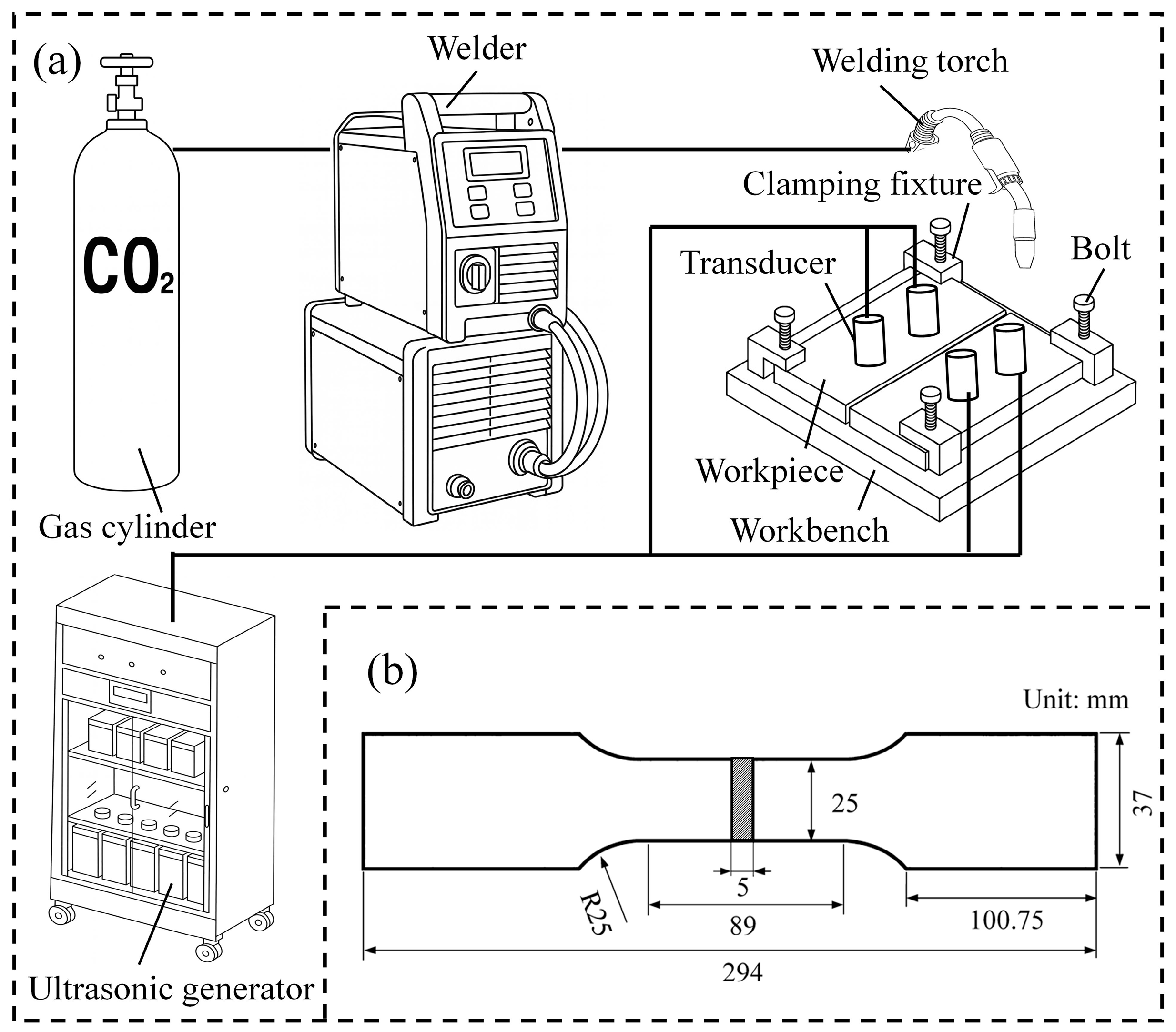
The experimental setup comprises three parts: welding system, ultrasonic system, and auxiliary tooling, as illustrated in Figure 1a. The welding system is a LINCOLN INVERTEC CV350 welding machine (Lincoln Electric, Cleveland, OH, USA) with 99.9%-purity CO2 as shielding gas. The ultrasonic system is a SONIC digital ultrasonic power supply (Qingda Ultrasonic Technology Co., Ltd., Ningbo, China), supported by a piezoelectric transducer with a base diameter of 60 mm and a resonant frequency of 20 kHz. Only one tensile specimen was obtained and tested for each welding condition, with dimensions shown in Figure 1b. The tensile test was carried out according to ISO 4136:2001 using a SANS SHT4305 universal testing machine (Shenzhen SANS Testing Machine Co., Ltd., Shenzhen, China) at a crosshead speed of 2 mm/min.Weld internal defects were examined by radiographic inspection according to NB/T 47013.2-2015 using a portable X-ray flaw detector (Huangshi Shangfang Detection Equipment Co., Ltd., Huangshi, China), and different models were selected depending on the penetrated thickness, i.e., XXG-2505 for thicknesses below 20 mm and XXG-3005 for thicknesses above 20 mm. Metallographic microstructures were examined using an OLYMPUS GX51 metallographic microscope (Olympus Corporation, Tokyo, Japan). Microhardness was measured using an automatic turret Vickers hardness tester (MHVS-30T, Shanghai Aolong Xingdi Testing Equipment Co., Ltd., Shanghai, China). Fracture surfaces of the tensile specimens were observed using a field-emission scanning electron microscope (Quanta FEG 450, FEI Company, Hillsboro, OR, USA), and the elemental composition was analyzed by energy-dispersive X-ray spectroscopy (EDS) using an EDAX system (EDAX Inc., Mahwah, NJ, USA).
Figure 1.
(a) Schematic of S-U GMAW setup; (b) dimensions of tensile specimen.
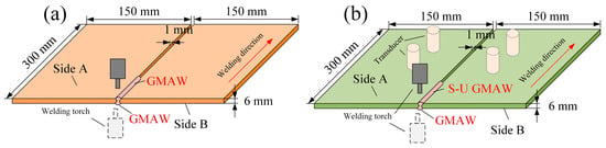
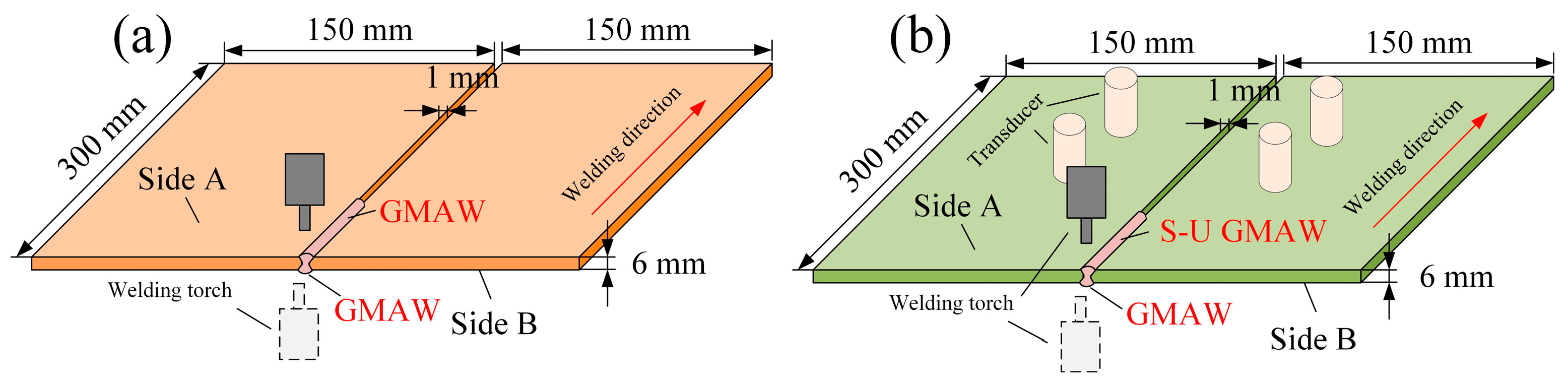
Rectangular base metal plates measuring 300 mm × 150 mm × 6 mm were prepared for butt welding without grooving. A 1 mm gap was maintained between the plates to be fixed, and then double-sided welding was performed. The two welding sides are defined as Side A and Side B. Side A is welded first, followed by Side B. To investigate the effect of ultrasound on welding deformation, microstructure, and mechanical properties, two test groups were established: (i) conventional GMAW on both sides, as shown in Figure 2a; and (ii) single-sided ultrasonic-assisted gas metal arc welding (S-U GMAW) applied on Side A with conventional GMAW on Side B, as shown in Figure 2b.
Figure 2.
Schematic of welding options: (a) GMAW; (b) S-U GMAW.
Both groups used the same GMAW parameters, and no special welding mode was applied. The only difference was that an ultrasound was applied to Side A in the S-U GMAW group. As shown in Figure 2b, four ultrasonic transducers were used, and each transducer was kept in tight contact with the base-metal surface during welding. Detailed welding parameters are summarized in Table 3.
Table 3.
Detailed welding parameters.
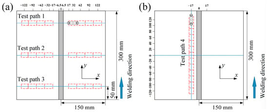
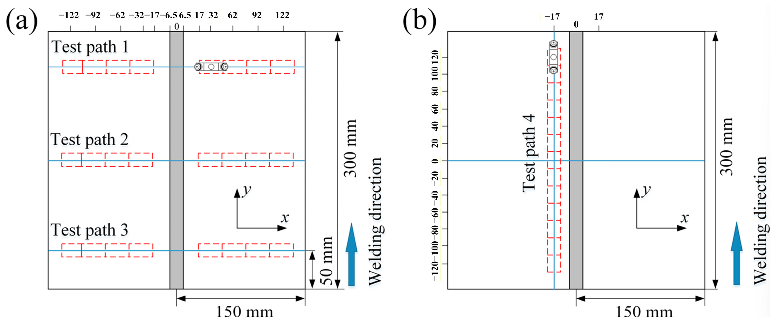
Residual stresses in the welded plates were measured using the longitudinal critically refracted (LCR) wave method in strict accordance with GB/T 32073-2015 [32], and the measurement paths are shown in Figure 3. Considering the directional nature of residual stress, both the y-direction stress parallel to the weld seam and the x-direction stress perpendicular to the weld seam were measured to fully characterize the residual stress state of the welded plates. Four measurement paths were used, including three paths along the x direction and one path along the y direction. The specific measurement points and their distances from the weld seam are indicated in Figure 3.
Figure 3.
Measurement paths and point locations for residual-stress evaluation using the LCR method: (a) transverse paths (Test paths 1–3); (b) longitudinal path (Test path 4).
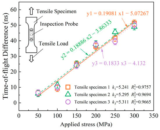
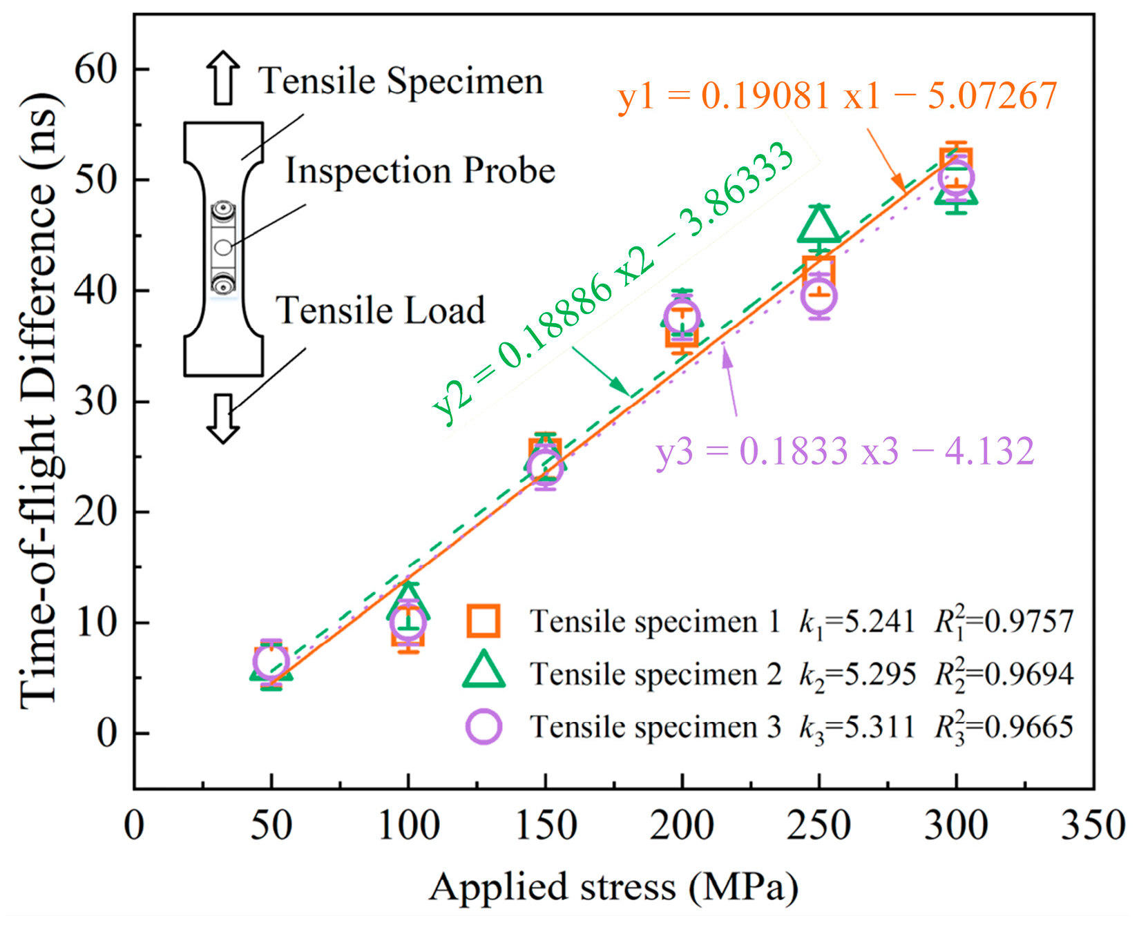
Based on the acoustoelastic principle, the stress coefficient for Q355 was calibrated in strict accordance with GB/T 32073-2015 [32]. Three tensile specimens machined from the base metal were subjected to uniaxial loading while the acoustic time difference Δt was recorded. Linear regression of stress σ against Δt was performed as shown in Figure 4, and the slope of the fitted σ–Δt relationship was taken as the stress coefficient. The coefficients from the three specimens were 5.241, 5.295, and 5.311 MPa/ns, and their mean value of 5.282 MPa/ns was used for residual stress evaluation in this study.
Figure 4.
Stress coefficient fit.
3. Results and Discussion
3.1. Macroscopic Morphology
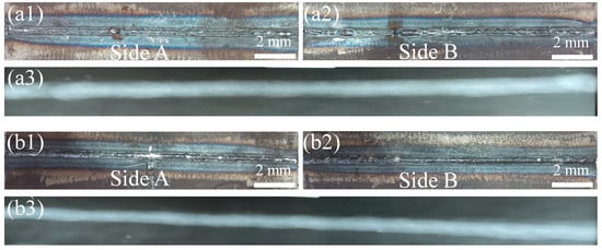
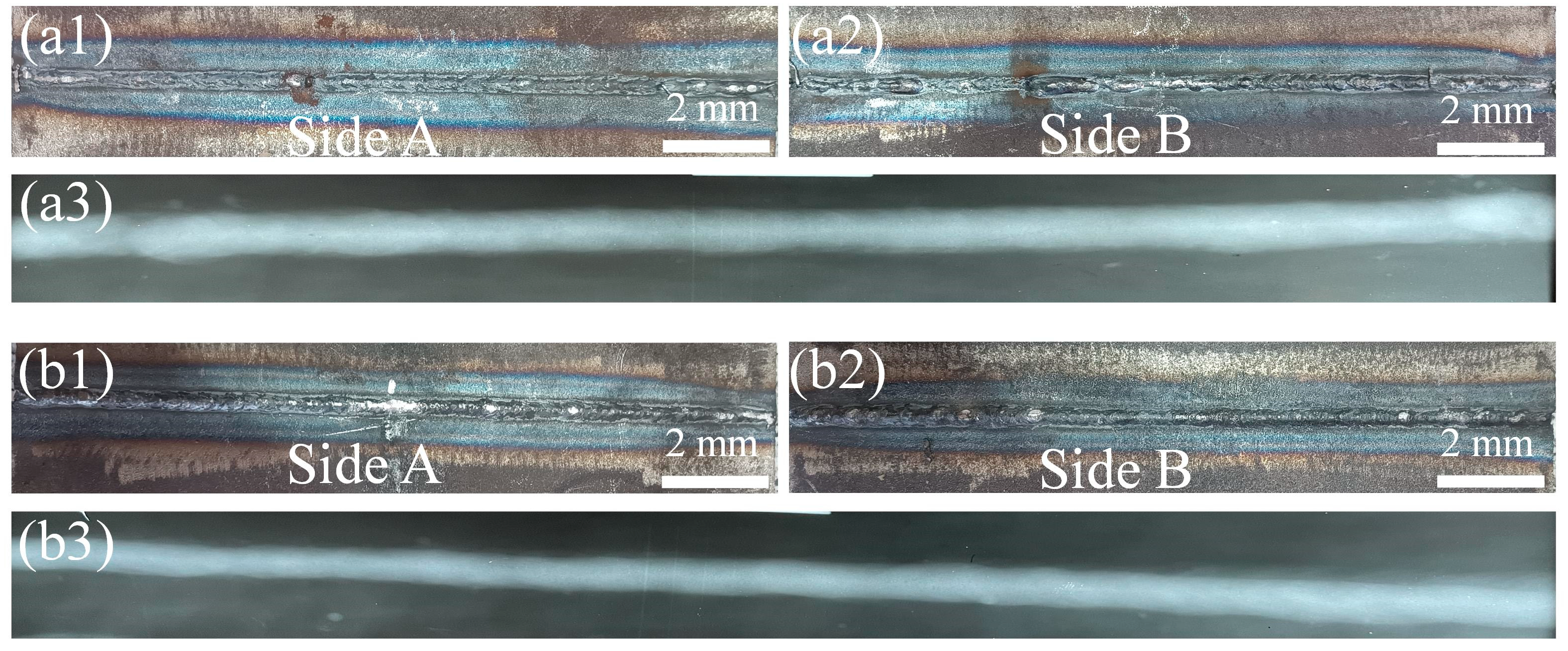
As shown in Figure 5, welds in the conventional GMAW group are relatively uniform and continuous on both Side A and Side B. However, surface ripples are coarse, spatter is prevalent, and the transition between the weld reinforcement and toe is uneven, as seen in Figure 5a1,a2. After the application of ultrasound, the S-U GMAW weld on Side A exhibits fine and regular ripples, straight pass edges, smooth toe transitions, and significantly reduced spatter, as illustrated in Figure 5b1. X-ray inspection results, shown in Figure 5a3,b3, reveal no continuous defects in either group.
Figure 5.
Weld appearance: (a1) Side A of the GMAW joint; (a2) Side B of the GMAW joint; (a3) X-ray inspection photo of the GMAW joint; (b1) Side A of the S-U GMAW joint; (b2) Side B of the S-U GMAW joint; (b3) X-ray inspection photo of the S-U GMAW joint.
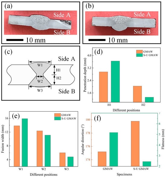
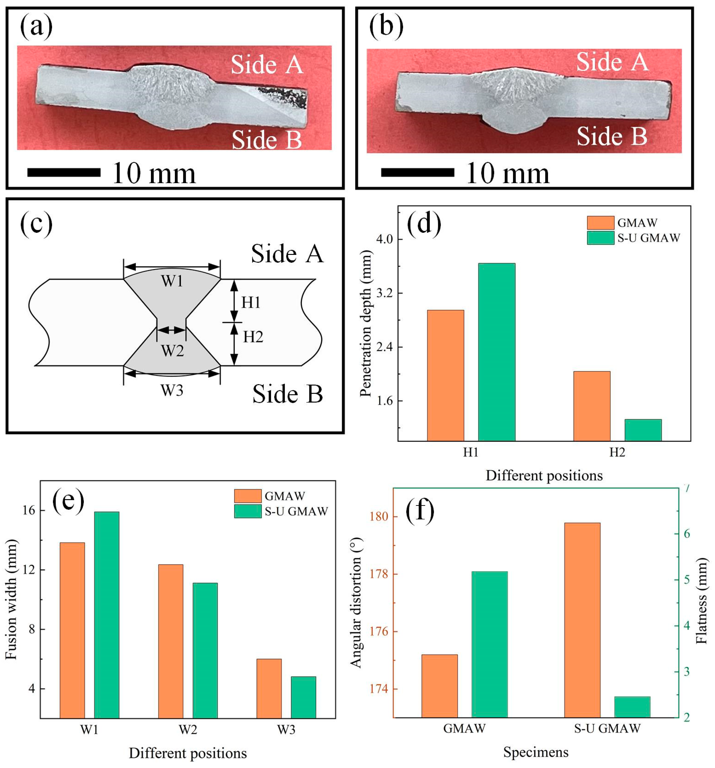
The macroscopic cross-sectional morphology of the welded joints is presented in Figure 6. A cross-section of the conventional GMAW joint is shown in Figure 6a, exhibiting a typical double-sided single-pass weld profile. Root contraction and undulations along the fusion boundaries are relatively pronounced, and the cross-sectional symmetry is moderate. A cross-section of the S-U GMAW joint is shown in Figure 6b. After the application of ultrasound, the molten pool on Side A exhibits finger-like deepening penetration, complete root bridging, a smoother contour, a well-defined fusion line, and a more balanced formation. This improvement can be attributed to the combined effects of acoustic radiation force and acoustic streaming, which establish a stable circulation within the molten pool. This circulation optimizes the temperature gradient during weld solidification, homogenizes the tension gradient on the pool surface, and promotes the spreading and self-leveling of liquid metal toward the weld toe, thereby reducing excess weld reinforcement and ensuring a smooth transition at the weld toe [33,34].
Figure 6.
Cross-sections of the welded joints: (a) GMAW; (b) S-U GMAW; (c) schematic of cross-sectional parameter measurement; (d) comparison of weld depths; (e) comparison of weld widths; (f) comparison of angular deformation and flatness.
As shown in Figure 6c, the geometric measurement method for cross-sectional fusion width and depth is schematically defined. The quantitative comparison of Figure 6d,e further indicates that the ultrasonic effect is predominantly exerted on Side A. In the S-U GMAW process, the fusion depth H1 on Side A increases significantly, whereas the fusion depth H2 on Side B remains nearly unchanged or slightly decreases compared to the conventional GMAW. This suggests that energy and metal flows are more concentrated on Side A. Additionally, the fusion width W1 increases in S-U GMAW, while W2 and W3 show corresponding convergence. The resulting differences in macroscopic deformation are illustrated in Figure 6f. Compared to conventional GMAW, the S-U GMAW exhibits smaller angular deformation and higher flatness. This indicates that ultrasound mitigates cumulative shrinkage and warpage caused by subsequent stacking on Side B, primarily through the optimization of temperature distribution and solidification profile. Specifically, the ultrasound-induced pool oscillation enables energy and metal flows to concentrate in the central region of Side A and expand toward the periphery of the weld toe, which increases the fusion depth and width, improves the wetting and filling at the weld gap, reduces the risk of incomplete penetration or lack of fusion, and contributes to a more symmetrical cross-sectional profile.
3.2. Phase Analysis
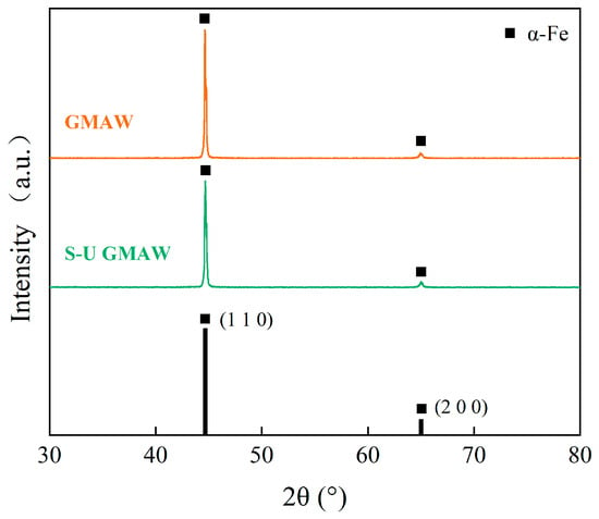
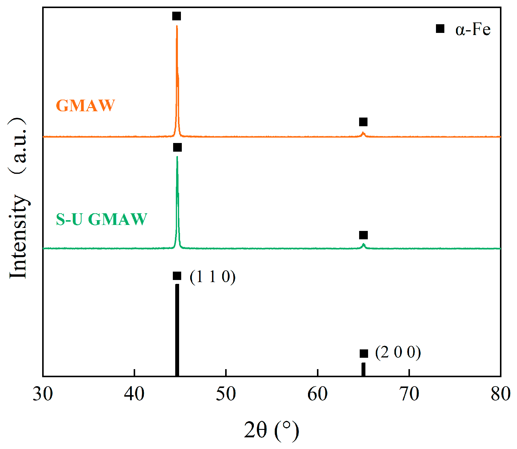
As shown in Figure 7, the XRD spectra of welds produced by both processes exhibit a stronger main peak at 2θ ≈ 44.7°, which corresponds to the (110) orientation of α-Fe (BCC), and a weaker peak at 2θ ≈ 65.0°, which corresponds to the (200) orientation of α-Fe [35]. No new peaks indicative of intermetallic compounds are observed in the spectra. The peak positions, relative intensities, and half-peak widths are nearly identical between the two groups, with no detectable shifts or new peaks indicative of phase transformation. Therefore, under these test parameters, ultrasound does not change the phase type of the weld metal, which remains predominantly ferritic.
Figure 7.
XRD test results for GMAW and S-U GMAW welds.
3.3. Microstructure
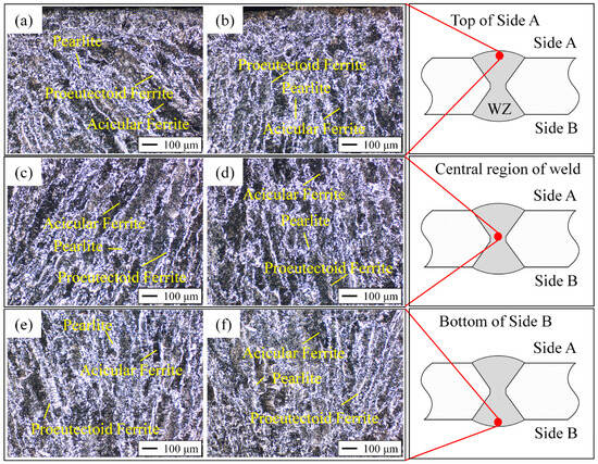
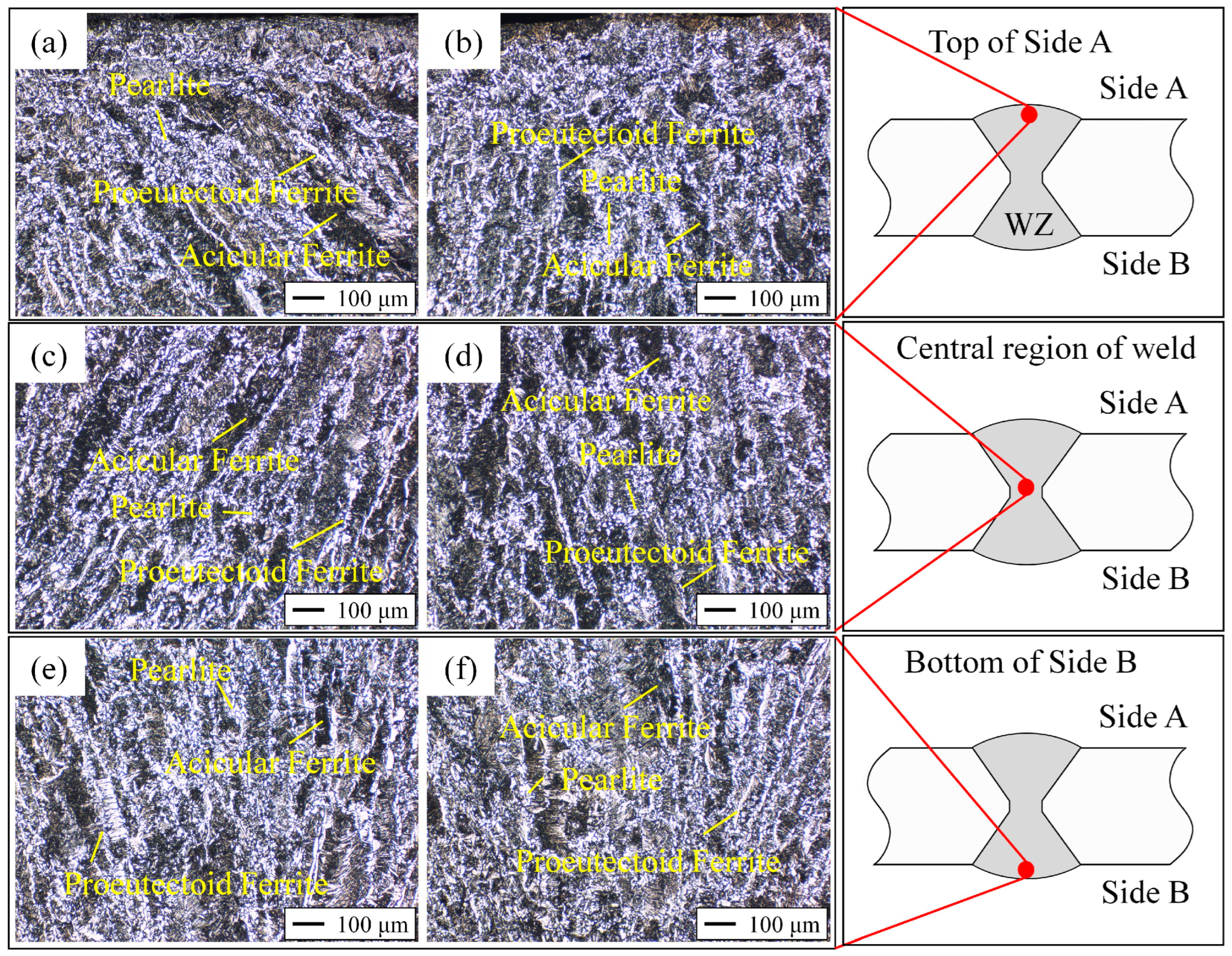
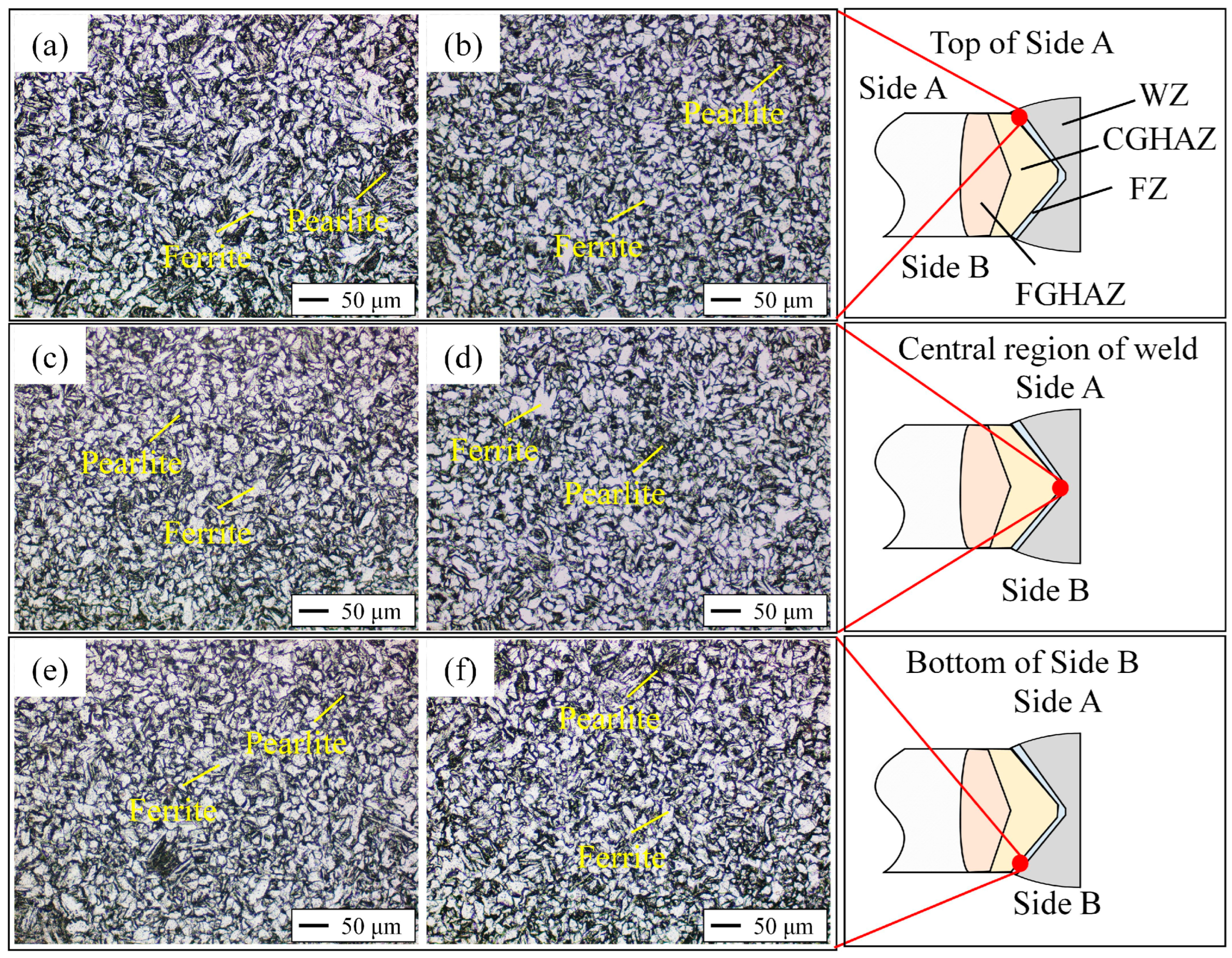
Figure 8 displays the optical microstructures at three typical locations—the top of Side A, the central region of the weld, and the bottom of Side B— within the weld zone (WZ). Welds produced by both processes consist primarily of ferrite, with a minor presence of pearlite [36,37]. Orientation bands originating from molten pool solidification are visible at the top of Side A and the bottom of Side B. Microstructure of the conventional GMAW weld is shown in Figure 8a,c,e. At the top of Side A, distinct columnar grain bands are observed, with clear grain boundaries and uniform orientation. In the central region of the weld, dendritic growth is more prominent, the equiaxed grain zone is narrower, and the overall grain size is coarser. At the bottom of Side B, a strong columnar orientation persists, the spacing between secondary dendrite arms is large, and the whole microstructure is inhomogeneous.
Figure 8.
Microstructure of WZ: (a,c,e) are the top of Side A, central region, and bottom of Side B of the GMAW weld, respectively; (b,d,f) are the top of Side A, central region, and bottom of Side B of the S-U GMAW weld, respectively.
Microstructure of the S-U GMAW weld is shown in Figure 8d–f. Significant grain refinement and equiaxed grain formation are observed across all three regions. At the top of Side A, the columnar character is diminished, the proportion of equiaxed ferrite is increased, and the surface layer appears denser. In the central region of the weld, dendrite growth is disrupted, grain size is reduced, and the orientation gradient is lowered. At the bottom of Side B, a uniform mixture of equiaxed ferrite and fine pearlite is also observed, with a narrowed columnar band width.
Compared to conventional GMAW, the S-U GMAW specimens exhibit a significantly reduced microstructural gradient through the thickness direction, with a narrower distribution of grain sizes. This suggests that the acoustic streaming effect of ultrasound induces convection within the molten pool, enhances pool nucleation, suppresses preferential grain growth, and accelerates heat transfer and solidification, thereby achieving the synergy of grain refinement and equiaxed grain formation.
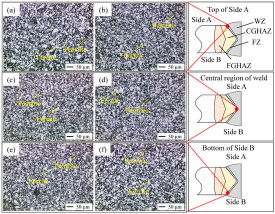
Figure 9 presents the microstructural morphology of the fusion zone (FZ) at the three sampling locations. Both processes feature a ferrite matrix with dispersed pearlite. In the conventional GMAW, flaky or lath-like grains are prevalent at the top of Side A, the bottom of Side B, and the central region. The fraction of equiaxed grains is low, and the grain size distribution is broad. This indicates that the recrystallization and phase transformation caused by temperature gradients are dominated by preferential grain growth.
Figure 9.
Microstructure of FZ: (a,c,e) are the top of Side A, central region, and bottom of Side B of the GMAW weld, respectively; (b,d,f) are the top of Side A, central region, and bottom of Side B of the S-U GMAW weld, respectively.
In contrast, the S-U GMAW weld exhibits a higher volume fraction of equiaxed ferrite and finer pearlitic colonies at all three locations. Flaky structures are markedly reduced, grain boundaries are clearly delineated, and the overall grain size is smaller. Especially, grain refinement is the most significant at the top of Side A. In the central region and the bottom of Side B, grains are still fine, uniform, and particulate. This suggests that the enhanced convection and nucleation within the molten pool induced by ultrasound increase the recrystallization nucleation rate and shorten the time of diffusion-driven preferential growth, mainly because the acoustic streaming effect under ultrasonic action affects the heat transfer of the molten pool. These microstructural differences provide a microscopic basis for the subsequent changes in hardness and tensile strength [38].
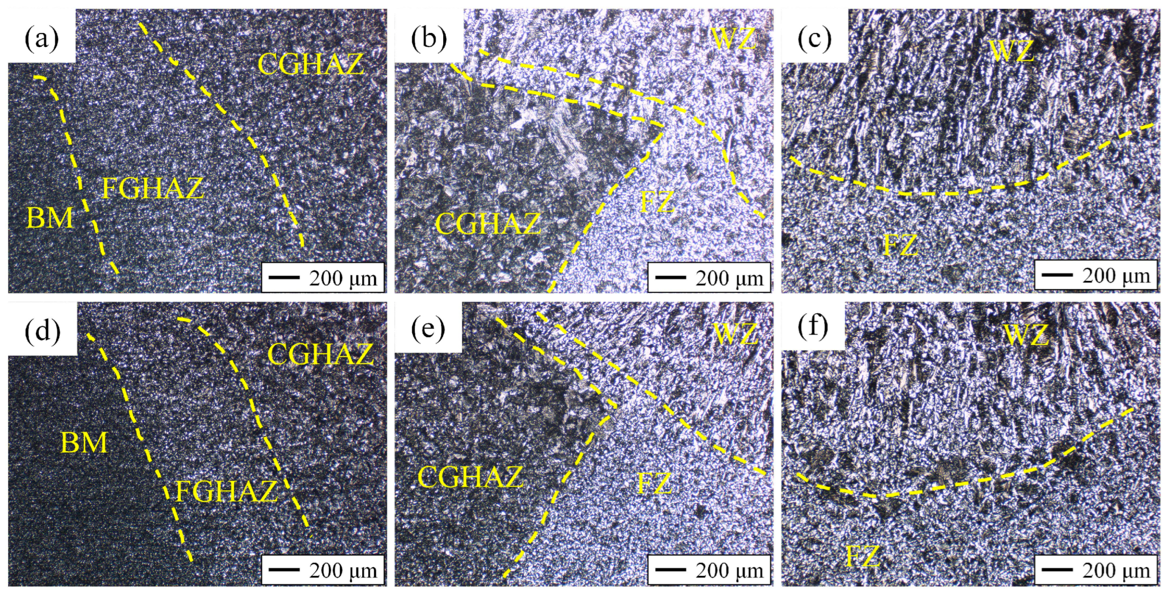
Figure 10 presents the FZ at the interface between the upper and lower weld layers. In the conventional GMAW, the grain size distribution within the fine-grained heat-affected zone (FGHAZ) is broad, and the orientation band near the fusion line is clear, indicating a high thermal peak and preferential grain growth, as shown in Figure 10a. The coarse-grained heat-affected zone (CGHAZ) exhibits significantly coarsened pre-austenite grains, increased laths, and a pronounced microstructural gradient, as depicted in Figure 10b. The WZ, as illustrated in Figure 10c, features strongly oriented columnar dendrites adjacent to the fusion line, wide spacing between secondary dendrite arms, evident solidification marks, and a narrow equiaxed zone.
Figure 10.
FZ between the upper and lower weld layers: (a–c) represent the FGHAZ, CGHAZ, and WZ of the GMAW weld, respectively; (d–f) represent the FGHAZ, CGHAZ, and WZ of the S-U GMAW weld, respectively.
S-U GMAW demonstrates a stable and refined FZ structure at the same locations. The proportion of equiaxed ferrite in the FGHAZ is increased, with finer and more uniformly distributed grains, and a less pronounced orientation band, as shown in Figure 10d. In the CGHAZ (see Figure 10e), grain coarsening is substantially weakened, the lath feature is diminished, pre-austenite equivalent grains become smaller, and the gradient is compressed. In the WZ (see Figure 10f), columnar dendrites are refined and partially transformed into equiaxed grains, the fusion line is straighter, the dendrite arm spacing is reduced, and the solidification zone is narrower.
These differences are closely associated with the influence of ultrasonic action. Ultrasound disrupts the growth of dendrites, thereby suppressing the preferential growth of columnar grains and promoting equiaxed grain formation. This leads to concurrent refinement of both the FGHAZ and CGHAZ at the interface, ultimately resulting in a narrower FZ and a more uniform grain distribution.
3.4. Mechanical Properties
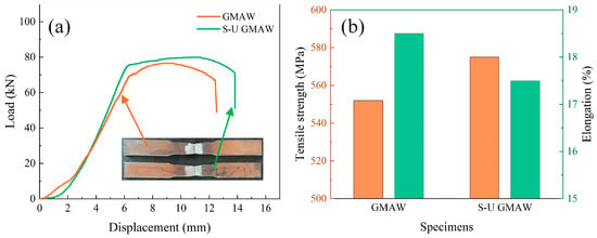
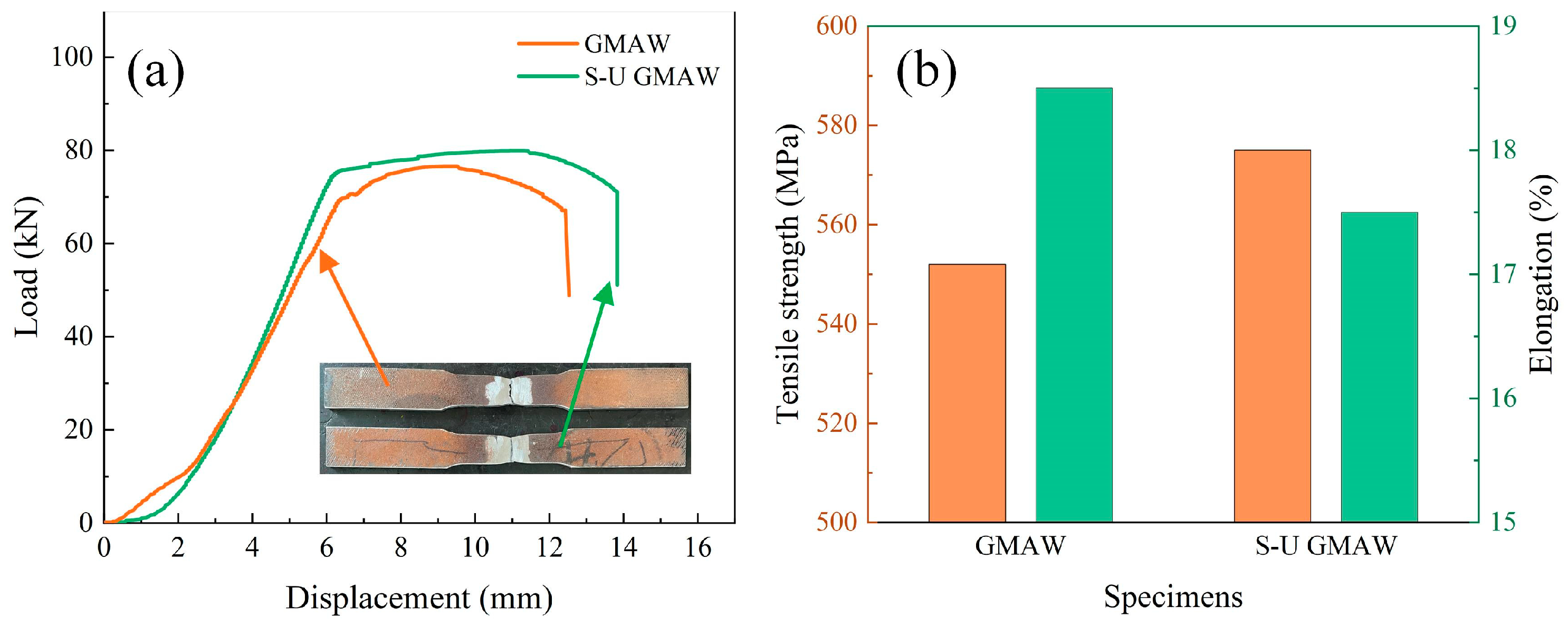
Only one tensile specimen was tested for each welding condition. Therefore, the tensile results are reported as single values and are not expressed as mean ± standard deviation. Figure 11 presents the tensile property analysis. In this single test, both tensile specimens fractured along the weld, indicating that the strength of the joint was governed by the weld and its adjacent areas. The slopes of the elastic segments in the load–displacement curves are nearly identical, suggesting comparable overall stiffness. However, in this single test, the S-U GMAW specimen showed a higher ultimate load and a more gentle post-peak load decline, which may indicate better weld continuity and fewer defects.
Figure 11.
Tensile properties: (a) tensile curves; (b) comparison of tensile strengths and elongations.
In this single test, the tensile strength of the conventional GMAW was 552 MPa with an elongation of 18.5%. The tensile strength of S-U GMAW was 575 MPa with an elongation of 17.5%. The difference in tensile strength may be related to the micro-structural refinement and equiaxed grain formation induced by ultrasonic action, which weakens orientation bands in both the FZ and WZ and reduces the defect content, thereby contributing to more uniform load transfer. The slightly lower elongation may be related to the increased strength and yield ratio, as well as the concentrated deep-penetration morphology that shortens the uniform plastic stage. Because the tensile results are single-test values, they should be interpreted as indicative trends and require replication to assess scatter. Similar single-specimen tensile reporting has been used in the literature when repeat testing is constrained by practical factors such as limited material volume or specimen availability. Louzguine-Luzgin and Edalati [39] reported that only one tensile specimen per condition could be prepared due to limited material volume after processing. Dzugan et al. [40] also reported that only one tensile test was conducted for standard-size specimens due to space limitations.
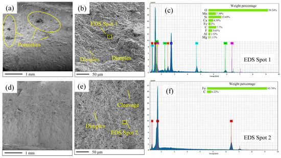
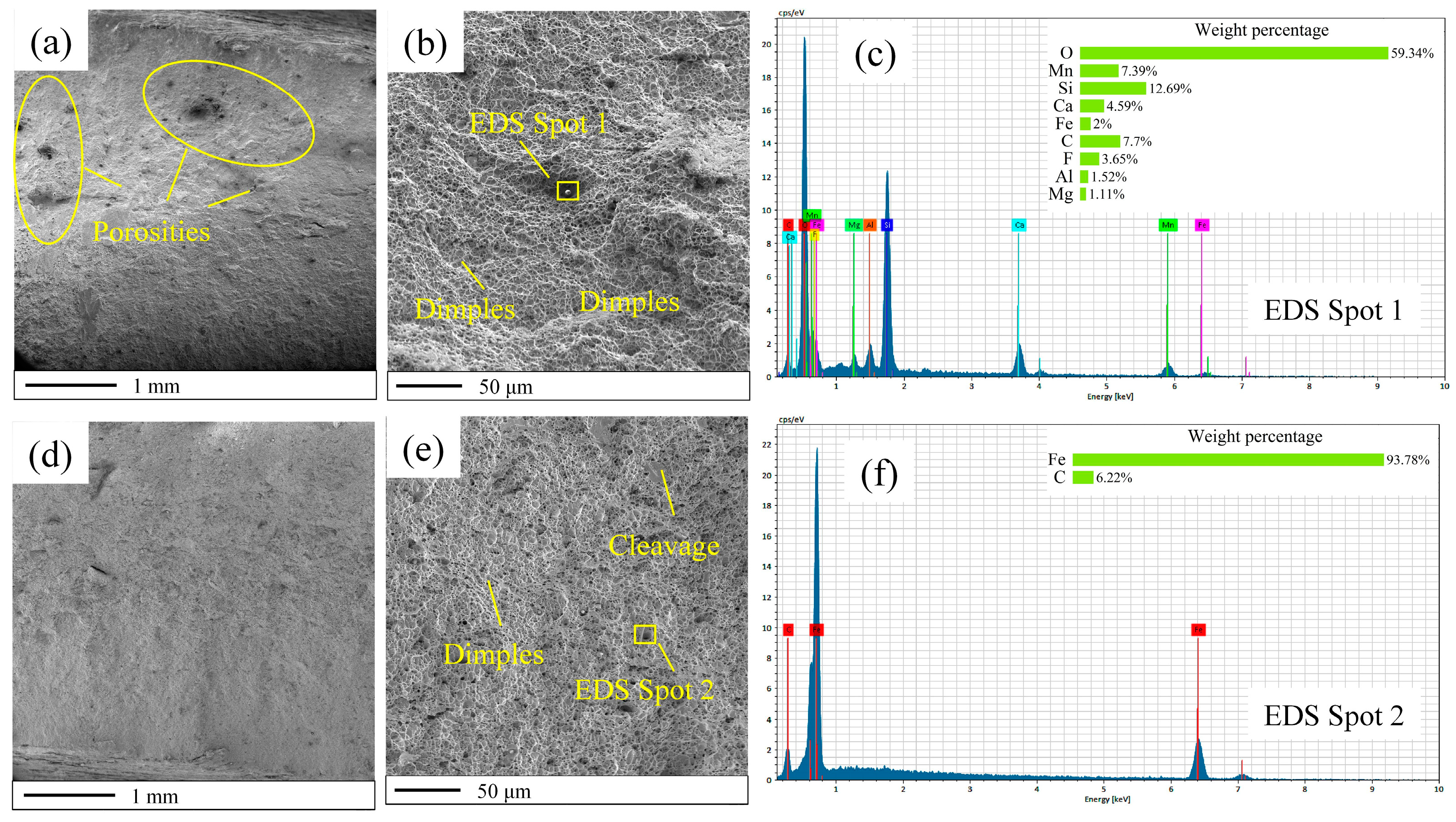
Figure 12 shows the fracture appearance and elemental composition of the joints produced by the two processes. Macroscopically, the fracture of the conventional GMAW specimen exhibits multiple pores and significant surface irregularities. Microscopically, it is dominated by large shallow dimples, with inclusion nuclei locally visible. A strong oxygen-rich signal is detected at the corresponding EDS positions, indicating the presence of composite oxide inclusions, which are prone to initiate microporosity and void-type fractures.
Figure 12.
Tensile fracture: (a–c) represent the macro-morphology, micro-morphology, and EDS test result of the GMAW tensile fracture, respectively; (d–f) represent the macro-morphology, micro-morphology, and EDS test result of the S-U GMAW tensile fracture, respectively.
The macroscopic fracture of the S-U GMAW specimen is smoother, with no apparent through-thickness pores. Microscopically, the fracture is dominated by fine, dense, and deep dimples that are uniformly distributed. However, small-scale quasi-cleavage steps are observed. The EDS detects only the presence of Fe and C, rather than a significant oxide signal, indicating the fracture occurrence within a purified metallic matrix. These findings align with the X-ray test results presented in Figure 5, suggesting that ultrasonic action may promote weld degassing and interface purification, which may reduce the likelihood of inclusion and pore formation. Additionally, the ultrasonic treatment refines microstructure and increases the nucleation rate, leading to a greater number of smaller microvoid nuclei and smaller and more uniform dimples [41].
The above fracture results explain the mechanical response observed in Figure 11. Pores and oxide inclusions in the GMAW fracture reduce the effective load-bearing area and introduce stress concentrations, which may contribute to the lower ultimate strength observed in the single test. In contrast, the S-U GMAW fracture is cleaner and dominated by fine dimples, which may facilitate more uniform load transfer and may be consistent with the higher strength observed in the single test. However, the presence of local quasi-cleavage features and refined dimples may be associated with a slight decline in elongation.
3.5. Microhardness
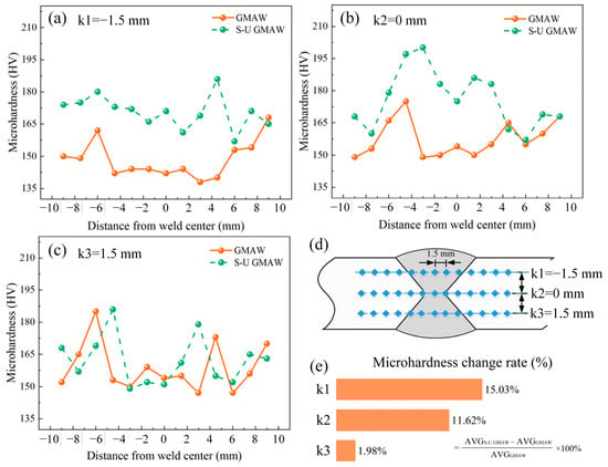
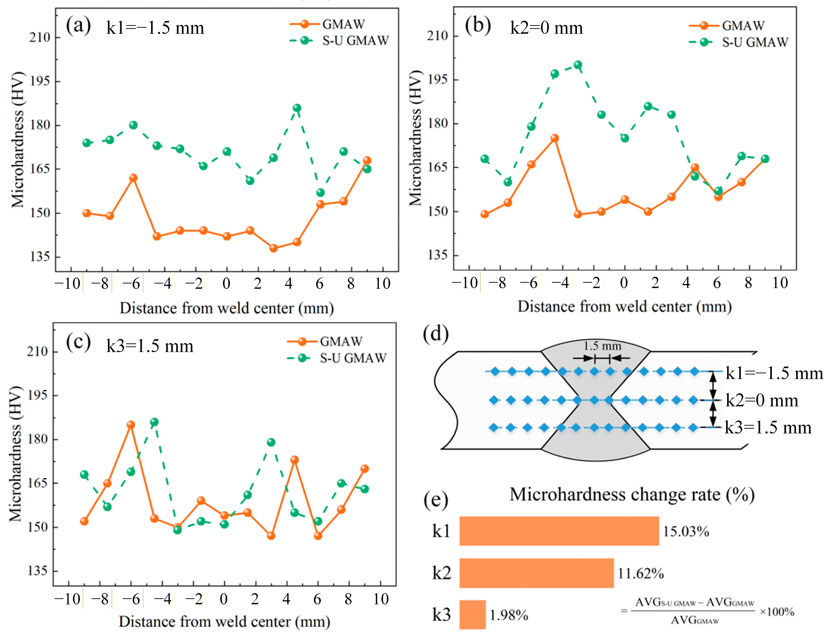
The microhardness distribution is shown in Figure 13. Microhardness was measured on one joint per condition. The reported average values were calculated from multiple indentation points along each measurement line. As illustrated in Figure 13d, the measuring lines are arranged from the weld centerline toward both sides and spaced 1.5 mm apart, designated as k1 (in the upper region of Side A), k2 (in the central region of the weld), and k3 (in the lower region of Side B). Compared with conventional GMAW, the S-U GMAW exhibits higher microhardness values along all three measuring lines, whose improvements, however, vary significantly. Based on the average values shown in Figure 13e, the hardness at k1 increases by approximately 15.03%, at k2 by about 11.62%, and at k3 by only 1.98%. As illustrated in Figure 13a,b, the S-U GMAW hardness in the upper region of Side A and the central region of the weld is always higher than that of the control group, with more pronounced hardness peaks and plateaus in the curve. However, the hardness in the lower region of Side B shows a limited improvement (see Figure 13c), indicating a smaller gap between the curves.
Figure 13.
Microhardness: (a–c) illustrate the microhardness values at different positions relative to the center of the weld; (d) is a schematic representation of the microhardness measurement points; (e) depicts the rate of change in microhardness.
These differences arise from the single-pass, double-sided welding sequence (Side A is welded first, followed by Side B) and the effect of ultrasound on the molten pool on Side A. Under ultrasonic action, Side A exhibits a higher nucleation rate and a shorter solidification time, leading to the formation of refined equiaxed grains in both the WZ and HAZ. According to the Hall-Petch relationship, the hardness at k1 and k2 increases significantly [42]. Since Side B is not directly exposed to ultrasound, the average hardness at k3 shows the smallest improvement. As seen from the three measuring lines, ultrasonic action extends the high-hardness region from the surface layer to the mid-thickness of the plate and weakens the softening trend in the thickness direction, which may be consistent with the higher tensile strength observed in the single test.
3.6. Residual Stress
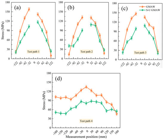
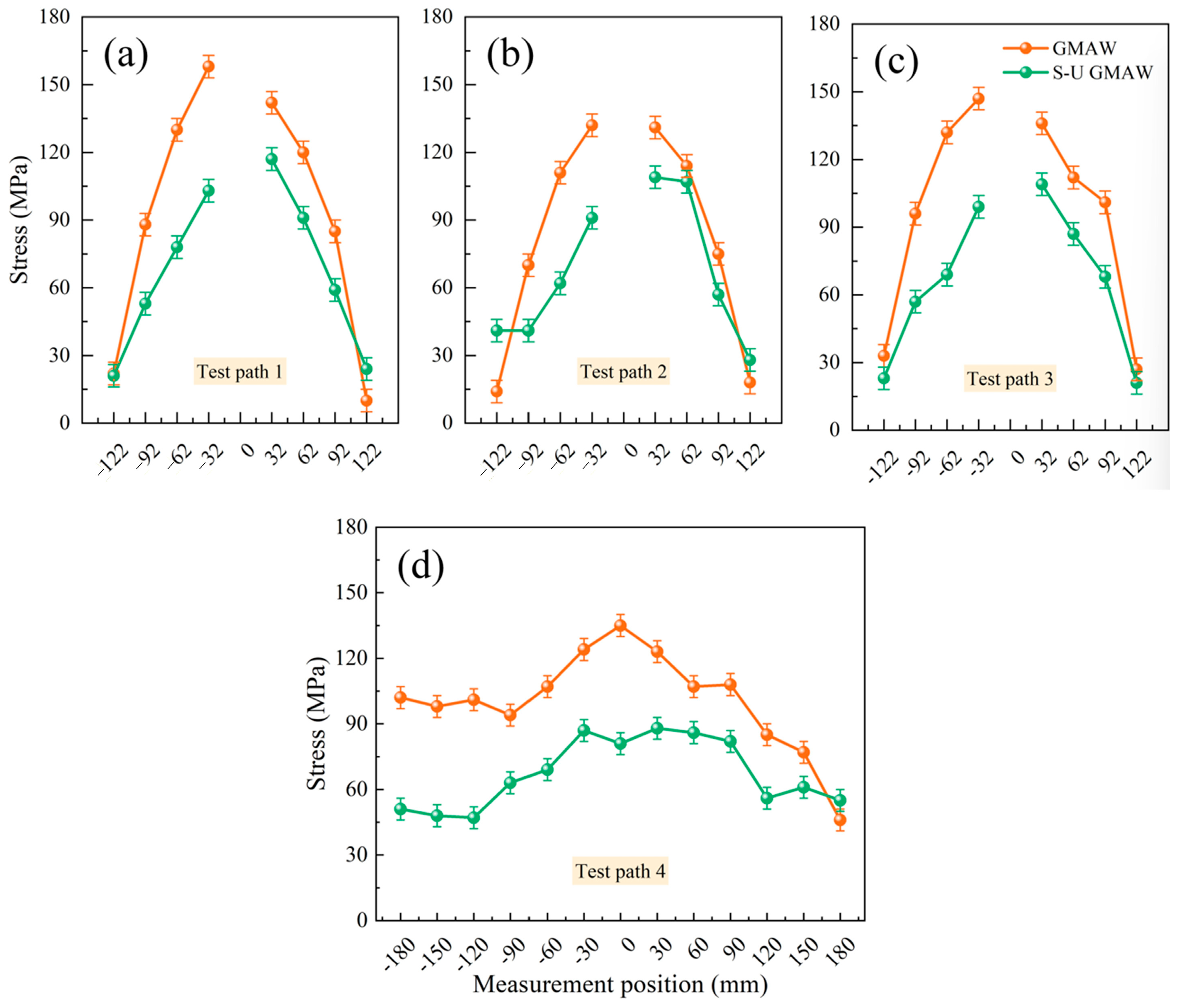
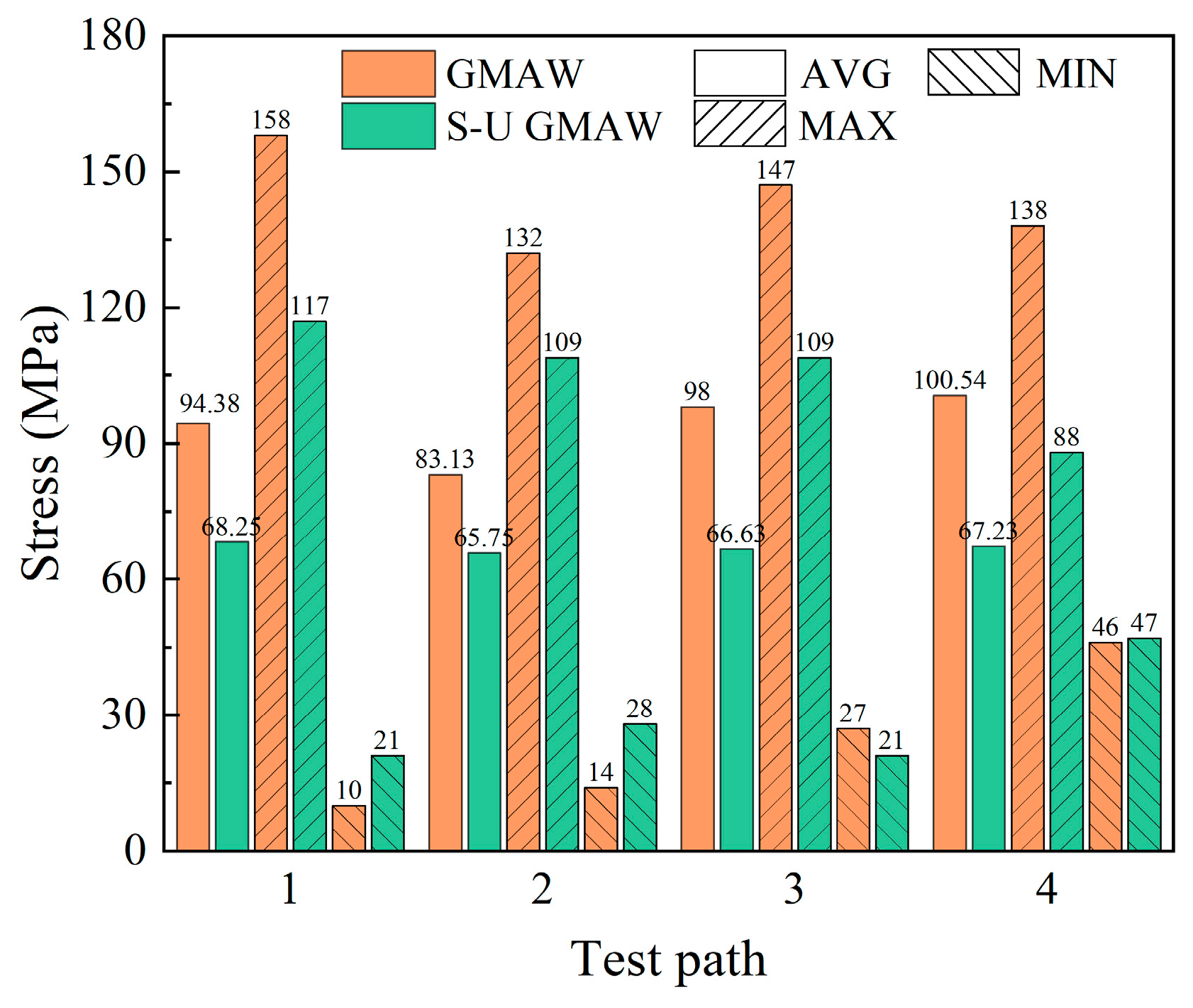
Residual stresses were measured using the LCR method in strict accordance with GB/T 32073-2015. Residual stresses were measured on one welded plate per condition. The mean and standard deviation were calculated from the measurement points along each path. The measurement paths and point locations are defined in Figure 3. The stress coefficient used for stress calculation was calibrated from the Δt–σ fitting in Figure 4. Figure 14 illustrates the residual stress distributions along four test paths. The Paths 1 to 3 exhibit a typical arc-shaped distribution profile, characterized by peak stresses at the center and a gradual decrease toward both sides. Compared with conventional GMAW, the S-U GMAW curve demonstrates a general downward shift across the entire range, which is the most significant at peak values. Specifically, the peak stresses along Paths 1, 2, and 3 decrease from 158, 132, and 147 MPa to 117, 109, and 109 MPa, respectively, and the stress levels in the edge regions also converge. Along Path 4, stress fluctuations are markedly reduced in the weld direction. The peak stress for GMAW is approximately 138 MPa, whereas that for S-U GMAW is about 88 MPa in a flatter curve. This indicates that ultrasound exerts a strong inhibitory effect on tensile stress amplitude along the weld direction.
Figure 14.
Distribution of residual stresses measured by the LCR method along different test paths: (a) Test path 1; (b) Test path 2; (c) Test path 3; (d) Test path 4.
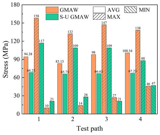
Figure 15 presents a statistical comparison across the four test paths, with results consistent with those shown in Figure 14. In terms of average values, the reduction rates of S-U GMAW relative to GMAW are approximately 27.7%, 21.0%, 32.0%, and 33.1% for the respective paths. This finding suggests that ultrasonic action not only reduces the overall tensile stress level in the transverse section but also effectively weakens high-stress zones along the longitudinal direction. A comparison of extreme values reveals a substantial decrease in the maximum stress values for all S-U GMAW paths, especially longitudinal Path 4 (with the maximum decrease). Accordingly, the standard deviation decreases across all paths, indicating a more uniform stress distribution.
Figure 15.
Extreme values and standard deviations of residual stresses.
By comparing the residual stress values between GMAW and S-U GMAW, the stress reduction rate α and equalization rate β induced by ultrasonic action were calculated using Equations (1) and (2), as summarized in Table 4. The α values for the four paths are 25.95%, 17.42%, 25.85%, and 36.23%, respectively. The α value for Path 4 is the highest, indicating that ultrasound suppresses most effectively the peak tensile stress in the y-direction. The corresponding β values are 35.19%, 35.37%, 28.77%, and 30.92%, respectively, demonstrating an improvement in stress dispersion across all paths. Particularly, favorable equalization effects are observed in Paths 1 and 2.
where and denote the maximum residual stresses for GMAW and S-U GMAW on the same path, respectively; and represent the standard deviations of residual stress values for GMAW and S-U GMAW on the same path, respectively.
Table 4.
Reduction and equalization rates of residual stresses for S-U GMAW compared to GMAW.
Ultrasonic waves induce acoustic streaming and radiation forces within the molten pool, thus promoting a more uniform distribution of heat and chemical components, a lower temperature gradient and a narrower HAZ. Furthermore, the cavitation effect of ultrasonic waves facilitates the removal of entrapped air and triggers dendrite breakage, leading to the formation of equiaxed grains and a uniform microstructure. The synergy of these effects optimizes the environment for weld solidification, thereby reducing the peak and average residual stresses and the spatial dispersion of stresses, and finally achieving the results of stress reduction and equalization.
4. Conclusions
This study compares conventional GMAW and S-U GMAW in terms of thin plate forming, microstructure, mechanical properties, and residual stress, and draws the following conclusions:
- (1)
- S-U GMAW improves weld forming quality, and EDS analysis indicates a cleaner weld metal matrix with no continuous defects observed.
- (2)
- In a single tensile test, the joint tensile strength was 552 MPa for GMAW and 575 MPa for S-U GMAW, while the elongation remains relatively high. Replication is required to evaluate scatter and statistical significance for the tensile results.
- (3)
- The weld microhardness is increased under S-U GMAW, with hardness values on Side A and at the weld center increasing by 15.03% and 11.62%, respectively, indicating microstructural refinement and strengthening.
- (4)
- S-U GMAW reduces and homogenizes the welding residual stresses, with peak stresses reduced by 25.95–36.23% and standard deviations reduced by 28.77–35.37%, particularly along the longitudinal path, thereby helping to control welding deformation.
Author Contributions
Conceptualization, P.Y. and L.W.; Methodology, P.Y. and C.X.; Software, W.L.; Validation, P.Y., W.L., Z.W. and T.H.; Formal analysis, T.H.; Investigation, P.Y., W.L. and C.X.; Resources, C.X. and L.W.; Data curation, W.L., Z.W. and T.H.; Writing—original draft preparation, P.Y.; Writing—review and editing, P.Y. and L.W.; Visualization, P.Y., C.X., Z.W. and T.H.; Supervision, C.X., Z.W. and L.W.; Project administration, L.W.; Funding acquisition, L.W. All authors have read and agreed to the published version of the manuscript.
Funding
This research and publication are supported by the project of “China Naval Equipment Development” (Grant No.: S102-2019-G110-03-001).
Data Availability Statement
The original contributions presented in this study are included in the article. Further inquiries can be directed to the corresponding authors.
Conflicts of Interest
Author Wenkai Li was employed by the company Beijing Materials Handling Research Institute CO., Ltd. The remaining authors declare that the research was conducted in the absence of any commercial or financial relationships that could be construed as a potential conflict of interest. The authors declare no other conflicts of interest.
References
- Liao, X.; Wei, H.; Pan, H.; Li, H.-T.; Sun, B.; Xin, H. Fatigue resistance of rib-to-bimetallic steel deck welded joints in orthotropic steel bridge decks. Thin-Walled Struct. 2024, 194, 111318. [Google Scholar] [CrossRef] [Scilit]
- Si, Q.; Ding, Y.; Zong, L.; Meng, X. Effect of pre-fatigue damage on static and hysteretic behavior of Q355 steel. Int. J. Fatigue 2022, 160, 106874. [Google Scholar] [CrossRef] [Scilit]
- Wang, F.; Yue, J.; Wang, W.; Shi, W. Unified fatigue life calculation of Q355B-16 mm steel notched plates considering crack initiation. Constr. Build. Mater. 2024, 437, 136972. [Google Scholar] [CrossRef] [Scilit]
- Li, X.X.; Hu, L.; Deng, D. Influence of contact behavior on welding distortion and residual stress in a thin-plate butt-welded joint performed by partial-length welding. Thin-Walled Struct. 2022, 176, 109302. [Google Scholar] [CrossRef] [Scilit]
- Pak, A.; Shams, H.; Rezaei Ashtiani, H.R.; Choopani, Y. A comprehensive study of ultrasonic-assisted gas metal arc welding of high-strength steel. Ultrasonics 2024, 138, 107242. [Google Scholar] [CrossRef] [Scilit]
- Trinh, N.Q.; Tashiro, S.; Le, K.D.; Suga, T.; Kakizaki, T.; Yamazaki, K.; Lersvanichkool, A.; Murphy, A.B.; Bui, H.V.; Tanaka, M. Eligible CO2 content in Ar-CO2 mixture shielding gas for improving metal transfer in metal-cored arc welding. Int. J. Heat Mass Transf. 2024, 231, 125803. [Google Scholar] [CrossRef] [Scilit]
- Chen, F.; Zhang, H.; Li, Z.; Luo, Y.; Xiao, X.; Liu, Y. Residual stresses effects on fatigue crack growth behavior of rib-to-deck double-sided welded joints in orthotropic steel decks. Adv. Struct. Eng. 2024, 27, 35–50. [Google Scholar] [CrossRef] [Scilit]
- Shen, W.; Wu, G.Y.; Huang, S.; Xu, S.X.; Liu, K.; Kai, Q. Nonlinear mechanical behavior and stress amplification effect correction of thin plate welded structure considering initial deformation. J. Constr. Steel Res. 2024, 213, 108409. [Google Scholar] [CrossRef] [Scilit]
- Chen, F.; Liu, Q.; Lu, Y.; Luo, Y.; Xiao, X.; Liu, Y.; Chen, B.; Zhang, H.; Chen, Y. Fatigue reliability assessment of rib-to-deck double-sided welded joints in orthotropic steel decks considering welding residual stress. Sci. Rep. 2024, 14, 31418. [Google Scholar] [CrossRef] [Scilit] [PubMed]
- Mancini, F.; Sandgren, J.; Lehto, P.; Remes, H. Experimental validation of an analytical stress magnification factor for thin plates with welding-induced curvature. Ships Offshore Struct. 2025. Online. [Google Scholar] [CrossRef] [Scilit]
- Yu, S.; Li, D.; Ou, J. Digital twin-based structure health hybrid monitoring and fatigue evaluation of orthotropic steel deck in cable-stayed bridge. Struct. Control Health Monit. 2022, 29, e2976. [Google Scholar] [CrossRef] [Scilit]
- Sun, J.; Dilger, K. Influence of welding sequence and external restraint on buckling distortion in thin-plate arc-welded joints. J. Adv. Join. Process. 2023, 8, 100157. [Google Scholar] [CrossRef] [Scilit]
- Rossini, L.F.S.; Reyes, R.A.V.; Spinelli, J.E. Double-wire tandem GMAW welding process of HSLA50 steel. J. Manuf. Process. 2019, 45, 227–233. [Google Scholar] [CrossRef] [Scilit]
- Akyel, F.; Olschok, S.; Reisgen, U. Reduction of distortion by using the low transformation temperature effect for high alloy steels in electron beam welding. Weld. World 2021, 65, 23–34. [Google Scholar] [CrossRef] [Scilit]
- Ordieres, J.; Rodríguez, E.; Bayón, A.; Caixas, J.; Barbensi, A.; Martín, C. Determination of the influence of clamping on welding distortion applied to PS2 mock-up using finite element simulations. Fusion Eng. Des. 2021, 166, 112327. [Google Scholar] [CrossRef] [Scilit]
- Wang, J.; Zhou, X.; Yi, B. Buckling distortion investigation during thin plates butt welding with considering clamping influence. CIRP J. Manuf. Sci. Technol. 2022, 37, 278–290. [Google Scholar] [CrossRef] [Scilit]
- Li, X.X.; Hu, L.; Fang, S.C.; Deng, D. Influence of clamping on out-of-plane deformation in thin-plate mild steel welded structures. J. Mater. Res. Technol. 2023, 25, 4380–4395. [Google Scholar] [CrossRef] [Scilit]
- Xia, L.; Zhou, J.; Xue, R.; Li, X.; Liu, H. Real-time seam tracking during narrow gap GMAW process based on the wide dynamic vision sensing method. J. Manuf. Process. 2023, 101, 820–834. [Google Scholar] [CrossRef] [Scilit]
- Kumar, K.V.S.; Gejendhiran, S.; Prasath, M. Comparative investigation of mechanical properties in GMAW/GTAW for various shielding gas compositions. Mater. Manuf. Process. 2014, 29, 996–1003. [Google Scholar] [CrossRef] [Scilit]
- Li, Y.; Geng, S.; Li, J.; Fan, Z.; Han, C.; Jin, J.; Jiang, P. Determination of residual stress in hybrid laser-arc welded U-rib-to-deck joints by thermo-metallo-mechanical simulation and neutron diffraction. Thin-Walled Struct. 2025, 208, 112755. [Google Scholar] [CrossRef] [Scilit]
- Hübner, M.; Dittmann, F.; Kromm, A.; Varfolomeev, I.; Kannengießer, T. Residual stress reduction using a low transformation temperature welding consumable with focus on the weld geometry. Weld. World 2025, 69, 3129–3139. [Google Scholar] [CrossRef] [Scilit]
- Pankaj, P.; Biswas, P.; Kim, D. Computational fluid dynamics based multi-species transport simulation of auxiliary energy systems for friction stir welding of dissimilar materials. CIRP J. Manuf. Sci. Technol. 2024, 52, 188–211. [Google Scholar] [CrossRef] [Scilit]
- Chen, G.; Hirohata, M.; Hyoma, K.; Matsumoto, N.; Inose, K. Deformation and residual stress of T-shaped joints fabricated by laser-arc hybrid welding for steel bridge members. Weld. World 2024, 68, 459–473. [Google Scholar] [CrossRef] [Scilit]
- Tan, C.; Li, R.; Su, J.; Du, D.; Du, Y.; Attard, B.; Chew, Y.; Zhang, H.; Lavernia, E.J.; Fautrelle, Y.; et al. Review on field assisted metal additive manufacturing. Int. J. Mach. Tools Manuf. 2023, 189, 104032. [Google Scholar] [CrossRef] [Scilit]
- Li, X.; Wang, W.; Wu, Y.; Zhou, D.; Kang, H.; Guo, E.; Li, J.; Chen, Z.; Xu, Y.; Wang, T. Ultrasonic field-assisted metal additive manufacturing (U-FAAM): Mechanisms, research and future directions. Ultrason. Sonochem. 2024, 111, 107070. [Google Scholar] [CrossRef] [Scilit] [PubMed]
- Ji, F.; Hu, Z.; Qin, X.; Yin, F.; Ni, M.; Xiong, X. Grain refinement and mechanism of steel in ultrasound assisted wire and arc additive manufacturing. Int. Commun. Heat Mass Transf. 2023, 143, 106724. [Google Scholar] [CrossRef] [Scilit]
- Liu, Z.; Zhang, D.; Jin, X.; Yu, C. Suppression of deformation and enhancement of weld properties in thin stainless steel using synchronous heat sink + ultrasonic hybrid laser welding. J. Mater. Process. Technol. 2023, 322, 118215. [Google Scholar] [CrossRef] [Scilit]
- Wei, M.; Zheng, S.; Chen, Y.; Xu, M.; Min, W.; Wang, S.; Zhang, T.; Xie, J. Microstructural evolution and mechanical performances of AZ31 magnesium alloy fabricated by ultrasonic vibration-assisted CMT wire arc additive manufacturing. Mater. Today Commun. 2025, 49, 113989. [Google Scholar] [CrossRef] [Scilit]
- Zohourmesgar, M.; Shoja Razavi, R.; Reza Dehnavi, M.; Sheykholeslami, M.R.; Khandaei, M. Effect of ultrasonic vibrations on mass efficiency and microstructure of laser direct deposition Inconel 718 superalloy. Ultrason. Sonochem. 2024, 111, 107124. [Google Scholar] [CrossRef] [Scilit]
- GB/T 1591-2018; High Strength Low Alloy Structural Steels. Standardization Administration of China: Beijing, China, 2018.
- GB/T 8110-2020; Wire Electrodes and Weld Deposits for Gas Shielded Metal Arc Welding of Non Alloy and Fine Grain Steels. Standardization Administration of China: Beijing, China, 2020.
- GB/T 32073-2015; Non-destructive Testing—Test Method for Measuring Residual Stress Using Ultrasonic Critical Refracted Longitudinal Wave. Standardization Administration of China: Beijing, China, 2015.
- Ji, F.; Qin, X.; Hu, Z.; Xiong, X.; Ni, M.; Wu, M. Influence of ultrasonic vibration on molten pool behavior and deposition layer forming morphology for wire and arc additive manufacturing. Int. Commun. Heat Mass Transf. 2022, 130, 105789. [Google Scholar] [CrossRef] [Scilit]
- El-Azab, S.A.; Zhang, C.; Jiang, S.; Vyatskikh, A.L.; Valdevit, L.; Lavernia, E.J.; Schoenung, J.M. In situ observation of melt pool evolution in ultrasonic vibration-assisted directed energy deposition. Sci. Rep. 2023, 13, 17705. [Google Scholar] [CrossRef] [Scilit] [PubMed]
- Duan, X.; Ge, F.; Liu, Y.; Zheng, H. Small-size and well-dispersed Fe nanoparticles embedded in carbon rods for efficient oxygen reduction reaction. Chem. Commun. 2024, 60, 3547–3550. [Google Scholar] [CrossRef] [Scilit] [PubMed]
- Zhang, S.C.; Yang, F.L.; Jia, H.D.; Chen, C.C.; Feng, Q.S.; Dai, L.S.; Zhang, Z. Study on the effect of microstructure on toughness dispersion of X70 steel girth weld. Eng. Fail. Anal. 2024, 164, 108671. [Google Scholar] [CrossRef] [Scilit]
- Wang, Y.; Li, R.; Wen, Q.; Xiao, W.; Wu, S.; Zhai, X.; Zhang, F. Comparison of Microstructure and Mechanical Properties of Ultra-Narrow Gap-Welded and Submerged Arc-Welded Q355E HSLA Steel. Materials 2025, 18, 2805. [Google Scholar] [CrossRef] [Scilit]
- Chen, Y.; Xu, M.; Zhang, T.; Xie, J.; Wei, K.; Wang, S.; Yin, L.; He, P. Grain refinement and mechanical properties improvement of Inconel 625 alloy fabricated by ultrasonic-assisted wire and arc additive manufacturing. J. Alloys Compd. 2022, 910, 164957. [Google Scholar] [CrossRef] [Scilit]
- Louzguine-Luzgin, D.V.; Edalati, K. Fe–Mn–Co–Al–C duplex high-entropy alloys with high hardness, high strength and good ductility processed via high-pressure torsion. J. Alloys Compd. 2025, 1045, 184597. [Google Scholar] [CrossRef] [Scilit]
- Dzugan, J.; Seifi, M.; Rund, M.; Podany, P.; Grylls, R.; Lewandowski, J.J. The Use of Miniature Specimens to Determine Local Properties and Fracture Behavior of LPBF-Processed Inconel 718 in as-Deposited and Post-Treated States. Materials 2022, 15, 4724. [Google Scholar] [CrossRef] [Scilit]
- Cui, B.; Chen, K.; Yang, Y.; Lv, Y.; Zhang, F.L.; Liu, S. Effect of ultrasonic vibration on the pores and properties of the laser-arc hybrid welding joint of high nitrogen steel. Mater. Chem. Phys. 2024, 318, 129297. [Google Scholar] [CrossRef] [Scilit]
- Kalayeh, P.M.; Mirzadeh, H.; Malekan, M.; Emamy, M.; Mahmudi, R. Improved hardness of Mg-0.5Ni-xY alloys via grain refinement and formation of LPSO structures. J. Mater. Res. Technol. 2024, 30, 6829–6835. [Google Scholar] [CrossRef] [Scilit]


Disclaimer/Publisher’s Note: The statements, opinions and data contained in all publications are solely those of the individual author(s) and contributor(s) and not of MDPI and/or the editor(s). MDPI and/or the editor(s) disclaim responsibility for any injury to people or property resulting from any ideas, methods, instructions or products referred to in the content. |
© 2026 by the authors. Licensee MDPI, Basel, Switzerland. This article is an open access article distributed under the terms and conditions of the Creative Commons Attribution (CC BY) license.