Abstract
Nickel superalloy Inconel 718 (IN718) is widely employed in harsh environments with prolonged cyclic stresses in the aerospace and energy sectors, due to its corrosion/oxidation resistance and mechanical strength obtained by precipitation hardening. This work investigates the mechanical behavior in fatigue of IN718 manufactured by Additive Manufacturing (AM), specifically by Laser Powder Bed Fusion (PBF-LB), and compares its results with the material produced by forging and rolling. Samples from both processes were subjected to heat treatments of solution and double aging to increase their mechanical strength. Then, tensile, microhardness, microstructural characterization, and uniaxial fatigue tests were performed (with loading ratio R = −1). The results showed that, although the IN718 produced by AM had higher microhardness and a higher tensile strength limit than the forged and rolled material, its fatigue performance was lower. The S–N curve (stress vs. number of cycles) for the material obtained by PBF-LB demonstrated shorter fatigue life, especially under low and medium stresses. The analysis of the fracture surfaces revealed differences in the regions where the crack initiated and propagated. The shorter fatigue life of the material obtained by PBF-LB was attributed to typical process defects and microstructural differences, such as the shape of the grains, which act as points of crack nucleation.
1. Introduction
Inconel 718 nickel alloy (IN718) is widely employed in harsh environments with prolonged cyclic stresses in the aerospace and energy sectors, due to its weldability, corrosion/oxidation resistance, and precipitation hardening after aging [1,2,3]. Laser Powder Bed Fusion (PBF-LB) has been adopted for combining geometric versatility and better use of raw material, and reducing time compared to forged or cast routes with machining [1,2]. In PBF-LB, high cooling rates and large thermal gradients generate out-of-equilibrium microstructures, with fine cells/dendrites, epitaxial growth, and preferential texture along the building direction [4,5]. The thermic variation promotes micro-segregation (especially of Nb) and favors the formation of the Laves phase in interdendritic regions, consuming Nb that would contribute to precipitation hardening [5,6].
To mitigate such constituents and stabilize the microstructure, thermal treatments such as solution followed by double aging (and hot isostatic pressing when relevant) are applied to dissolve the Laves phase, close pores, and precipitate γ′/γ″ in a controlled manner [4,6,7]. The performance of PBF-LB depends on the correct volumetric energy density. Low values can hinder melting, while high values can induce a steam cavity mode (unstable, with elongated pores). The intermediate level promotes the most stable conduction [8,9]. In addition, the scan strategy, layer thickness, and atmosphere define the melting regimes and, when controlled, reduce porosity and discontinuities [3,10,11].
In the function of combining cell refining with precipitation hardening caused by the process, at room temperature, parts produced in IN718 by PBF-LB can exhibit greater strength than those parts produced in IN718 by forging and after aging [10,12,13]. Under fatigue, the presence of remaining internal defects and microstructural heterogeneities can lead to the nucleation of cracks and reduce fatigue life, which is why characterization of the microstructure after heat treatment is central to interpreting the results [14,15]. Hence, the objective of the present work was to study how the solubilized and doubly aged state of the PBF-LB-manufactured IN718 affects fatigue performance, compared to the material obtained by forging and rolling, which was subjected to the same heat treatment.
2. Materials and Methods
The raw material for additive manufacturing was characterized by optical microscopy (BX60M, Olympus, Tokyo, Japan) and SEM (JSM-6510, JEOL, Tokyo, Japan). Particle size was statistically analyzed in ImageJ 1.0 software, based on individual measurements of 100 randomly selected particles from a representative sample.
The chemical composition was provided by the material suppliers: powder IN718 and the ingot used to manufacture the specimens by forging and rolling.
The preparation of the specimens by additive manufacturing (AM) began with the IN718 powder, which was previously dried in an oven to ensure good fluidity. The PBF-LB process was performed on an additive manufacturing machine (OmniSint-160, Omnitek, Campinas, Brazil), using the following specific parameters: 190 W laser power, 900 mm/s scanning speed, 0.03 mm layer thickness, and 0.07 mm between scanning lines, with an angle of 52° between the scanning directions of successive layers. This process manufactured rectangular bars with dimensions of 15 × 30 × 50 mm each. Subsequently, these bars were cut by the wire electrical discharge machining process to generate fatigue test specimens, as shown in Figure 1. All specimens were then subjected to a complete heat treatment in a muffle furnace. The cycle consisted of a solution at 1095 °C for 1 h with water cooling, followed by an initial aging at 720 °C for 8 h and a second aging at 620 °C for 8 h, both with air cooling. As a final finishing step, the samples were rectified and sanded in the recess regions to achieve a surface roughness of 0.15–0.30 Ra/1.55–2.40 Rz.
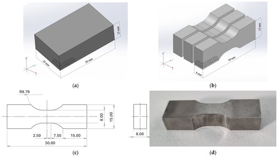
Figure 1.
Sequence of operations employed to manufacture the specimens for fatigue tests of Inconel 718 obtained by additive manufacturing, starting with (a) bar, (b) cutting by wire electro erosion, (c) technical drawing of the specimen, and (d) specimen after heat treatments.
For the specimens produced by forging and rolling, the process started from an ingot of the IN718 alloy. Initially, the material was heated in an LPG furnace to 1050 °C, with a controlled heating rate of approximately 216.8 °C per hour, the temperature being monitored by a certified optical pyrometer. Then, the anvil forging process in an open mold furnace took place in four steps: first squaring to a section of 86.6 mm, second to 77.4 mm, third to 54.9 mm, and, finally, rounding to a section of 55.4 mm in diameter. Throughout the forging, the material temperature was kept at a minimum of 850 °C, and the reduction per step was limited to a maximum of 20% to avoid defects. Prior to the rolling step, the bar was solubilized and then taken to a channel rolling mill, where it underwent a gradual reduction in diameter from 55.4 mm to a final 15 mm. After cooling, the bars were straightened and subjected to the same heat treatment cycle of solution and double aging previously described. Finally, the heat-treated bars were machined in a CNC lathe to produce the fatigue specimens, following the dimensions of ASTM E606/E606M-21 [16] guidelines, as shown in Figure 2. Table 1 summarizes the processing conditions of the samples and specimens.
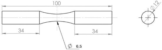
Figure 2.
Design of the specimen for fatigue tests of Inconel 718 obtained by forging and rolling.

Table 1.
Manufacturing and heat treatment conditions of the Inconel 718 and the abbreviations used to identify the specimens.
Figure 3 presents a schematic representation of the fabrication processes and heat treatment conditions employed.
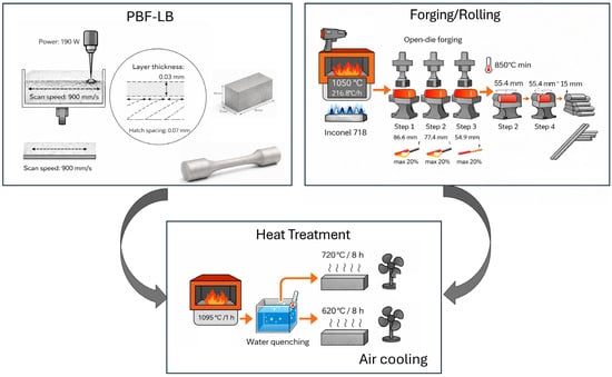
Figure 3.
Schematic representation of the fabrication processes and heat treatment conditions.
The characterizations of the samples began with the metallographic preparation. For this, the samples were hot embedded in bakelite and then sanded with silicon carbide sandpaper with sequential granulometries of 100, 240, 360, 400, 600, and 1200 mesh. Polishing was performed with 6 µm, 3 µm, 1 µm, and ¼ µm diamond pastes. To reveal the microstructure, a chemical etching was conducted by immersion in a Marble solution, composed of 10 g of CuSO4, 50 mL of HCl, and 50 mL of H2O for 60 to 100 s. Microstructural analysis was performed on an optical microscope (BX60M, Olympus, Tokyo, Japan), where images were captured before and after chemical etching, as well as on a scanning electron microscope (SEM), model (JSM-6510, JEOL, Tokyo, Japan). For the Vickers microhardness analysis, 15 measurements were performed on each sample using a automatic microdurometer, (EMCO-TEST, Zwick/Roell, Ulm, Baden-Württemberg, Germany), with a load of 100 gf (HV 0.1). X-ray diffraction (XRD) analyses were performed on a difratometer (MiniFlex, Rigaku, Tokyo, Japan), with a 2θ angle scanning range from 5° to 90° and a speed of 5° per minute.
Tensile tests were performed on two specimens of each condition (AM and forged and rolled) to obtain yield stress, tensile strength, and elongation. The tensile strength results were used to define fatigue test parameters. Because only two tensile specimens were available per condition (n = 2), the reported tensile properties should be regarded as reference values for fatigue stress scaling, and not as a statistically representative dataset. Therefore, the fatigue stress levels defined as percentages of UTS should be interpreted as nominal values within the uncertainty associated with tensile scatter. The fatigue tests were conducted on an servo-hydraulic machine, (8502, Instron, Norwood, MA, USA), equipped with a 100 kN load cell. In total, 23 specimens were tested: 13 obtained by AM and 10 by forging and rolling. Uniaxial fatigue tests were performed with loading ratio R = −1. The applied stresses were calculated as percentages of the tensile strength previously obtained in the tensile tests. The specimens were tested for the AM condition at stress levels of 70% (2 specimens), 60% (1 specimen), 50% (2 specimens), 40% (1 specimens), 30% (2 specimens), 25% (3 specimens), and 20% (2 specimens) of the tensile strength, while two specimens for the forged and rolled conditions were tested at 70%, 60%, 50%, 40%, and 30% of the tensile strength. The test was interrupted for specimens that reached 106 (one million) cycles without fracturing. After the mechanical tests, the fracture surfaces of the specimens of each condition were analyzed by SEM to identify the regions where the crack initiated, propagated, and finally ruptured.
3. Results and Discussion
3.1. Characterization or Raw Material Inconel 718 and Powder Particles
The micrograph of the optical microscopy of the IN718 powder shows the sectioned profile of the particles, visible in Figure 4a. A small quantity of defects was identified. Figure 4a also illustrates some defects in the shape of the particles and some pores found inside. Both form defects and pores in the particles are also recorded in the work of Moussaoui et al. [17]. Figure 4b is an SEM micrograph of the powder particles of Inconel 718 alloy. This image permits detailed examination of the morphological and topographic characteristics of the particles, with most particles having a well-defined spherical shape and relatively smooth surfaces—conditions that favor fluidity and packing density in the PBF-LB process.
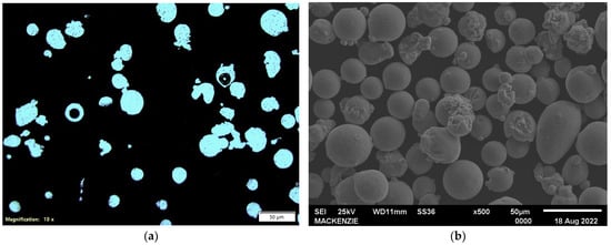
Figure 4.
Images of Inconel 718 powder particles observed by (a) optical microscopy and (b) scanning electron microscopy.
A statistical analysis of particle size was conducted through individual measurements on a representative sample containing 100 randomly selected particles. The average size determined was approximately 31 µm, with limit values between 18 µm and 48 µm. These dimensional data indicate that the powder used was within the grain size range recommended by the literature, ensuring stability during the deposition process of the layers and subsequent consolidation by PBF-LB, as described in the study by Kladovasilakis et al. [18] on the influence of PBF-LB process parameters applied to IN718 powder.
Table 2 shows the quantitative results, expressed as a mass percentage, referring to the chemical composition of the raw materials investigated in this work—the metallic powder of IN718 and the ingot of this same alloy, with information provided by the material supplier, as well as the reference values found in the literature. Observe that the measured chemical compositions are in accordance with the data reported in the literature, emphasizing the chemical consistency of the powder and ingot acquired for processing by AM.
Table 2.
Results in percentage of composition by mass of raw materials.
For the specific use in PBF-LB processes, the metallic powder IN718 utilized did not present any significant deviation from the recommended chemical composition, falling within the technical limits described in the literature. No metallic additives or modifying agents were incorporated, a practice that is sometimes adopted in studies to improve properties such as fluidity or reduce susceptibility to form defects during deposition and solidification. This decision is based on evidence that the addition of certain elements, such as yttrium (Y), can have an impact on the AM process. Borisov et al. [19] demonstrated that the incorporation of yttrium can lead to increased porosity of the samples and the presence of undissolved particles in the material matrix, even after heat treatments and double laser processing. These particles can be places where cracking initiates, compromising the structural integrity of the manufactured parts. Thus, the alloy investigated here maintained its original composition, fully preserving its original properties for application in PBF-LB.
3.2. Characterization of Inconel 718 Samples
Figure 5 displays micrographs obtained on the polished surface of the IN718 specimens obtained by AM before the chemical etching and illustrates the presence of some defects. Figure 4a exhibits a characteristic defect of the PBF-LB process, called the “keyhole” defect, formed during the localized fusion of the metallic powder by the laser beam. This type of defect often occurs during the intense interaction of the laser beam with the metallic powder, creating a deep cavity, which can solidify without complete filling due to instabilities in the melt pool.
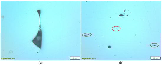
Figure 5.
Optical microscopy of the polished surface and without chemical etching of Inconel 718 obtained by Laser Powder Bed Fusion (PBF-LB), showing (a) “keyhole” defect and (b) “lack of fusion”.
Another type of defect is illustrated in Figure 5b and classified as “lack of fusion”. These defects occur due to insufficient or inadequate fusion between adjacent layers, creating regions of discontinuity in the consolidated structure. The lack of fusion may contain partially fused or unfused particles, due to the deposition of powder in subsequent layers. This phenomenon occurs especially when a gap formed in the deposition of layer “n” allows the accidental entry of particles from the subsequent layer (“n + 1”). These particles, which remain outside the effective melting zone, can end up partially embedded or totally loose in the cavities formed, impairing the local mechanical properties, and may compromise the structural performance of the parts produced by PBF-LB.
Figure 6 is the micrographs obtained from the polished surface of the IN718 produced by forging and rolling. Contrary to what was observed in the IN718 obtained by PBF-LB, this specimen exhibited a distinct distribution of apparent porosity. While it has a greater quantity of pores, they are much smaller, more dispersed, and distributed relatively evenly throughout the length of the analyzed surface. This porosity pattern, characterized by small dimensions and homogeneous dispersion, is directly associated with the specific conditions of the forging and rolling processing employed, possibly indicating minor problems related to incomplete melting and highlighting characteristics of the pore formation mechanism, such as gas retention or microvoids originating in the solidification process.
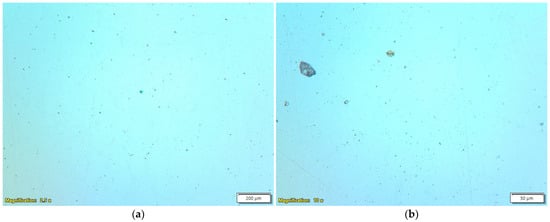
Figure 6.
Microscopy of the sample obtained by forging and rolling and solubilized/double-aged (FR-S-DA) before chemical etching (a) low magnification and (b) high magnification.
During the application of the chemical etching with Marble’s Reagent, a significant variation was observed in the time required for the proper development of the microstructures in the different samples analyzed. The exposure times that promoted satisfactory results in the chemical etching of IN718 were 80 s for the sample produced by PBF-LB and subjected to solution heat treatment, 70 s for the sample also produced by PBF-LB, but solubilized and subjected to double aging, and 100 s for the sample manufactured by forging and rolling. This time difference required to obtain a homogeneous etching is attributed to variations in microstructural conditions, originating from the different heat treatments and manufacturing methods applied to the studied specimens.
The solution heat treatment plays a key role in dissolving the secondary phases present in IN718, predominantly resulting in a matrix with homogeneous γ-phase. This transformation is evidenced by the comparison between the micrographs in Figure 7a,b. Figure 7a shows a pronounced dendritic microstructure, associated with the presence of the Laves phase, in as-built condition, which forms in the interdendritic regions during rapid solidification, characteristic of the PBF-LB process. These precipitates are sparse/localized and may remain below the XRD detection capability, which explains why δ-related peaks are not evident in the diffractograms. The presence of the Laves phase is reported in several works, including Park et al. [20], which characterizes these dendritic formations pointed to in Figure 7a as a focus of the Laves phase. The presence of this phase is undesirable, as it becomes a reservoir for Nb, preventing the formation of the γ″ reinforcement phases during aging, which compromises the mechanical properties of the material. Therefore, elimination of this phase via solution is essential to optimize the performance of IN718 manufactured by PBF-LB.
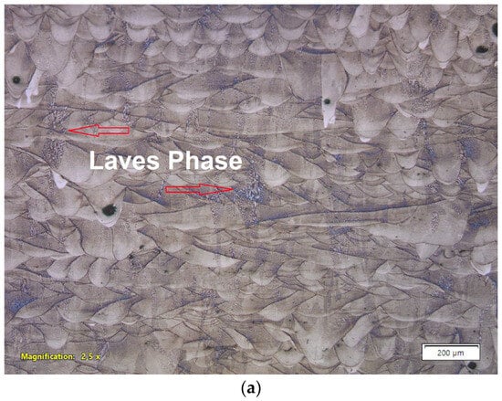
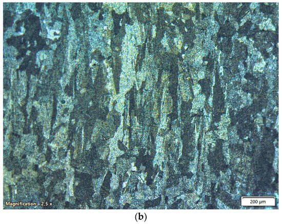
Figure 7.
Micrographs obtained by optical microscopy after chemical etching of the specimen manufactured by Laser Powder Bed Fusion (PBF-LB) in the (a) as-built condition and (b) after solution heat treatment (1095 °C/1 h).
After solution treatment at 1095 °C for 1 h, as shown in Figure 7b, this dendritic microstructure is no longer visible, indicating effective dissolution of the Laves phase. Figure 7b displays a columnar microstructure with a defined preferred orientation, aligned parallel to the growth direction of the part during the manufacturing process. The high cooling rates and the directional thermal gradient during solidification promote the epitaxial growth of the grains in the direction of heat flow, resulting in this columnar structure. In this case, the face analyzed is parallel to the original building direction of the piece.
Especially noteworthy, the effect of solution performed at 1095 °C for 1 h promoted a complete microstructural modification compared to the as-built condition by PBF-LB, shown in Figure 6a. The solution treatment at an elevated temperature, above the solvus temperature of certain phases (for example, the Laves phase), together with the time held at that temperature, allows dissolution or coalescence of precipitates and recrystallization and grain growth. Schneider et al. [21] discuss how the original dendritic structures recrystallize in well-defined grains and how the distribution and morphology of the precipitated phases are changed, addressing the difficulty of completely dissolving the Laves phase. These authors also mention that heat treatment provides recrystallization, which contributes to microstructural homogenization and elimination of the characteristics of the as-manufactured condition. Bassini et al. [22], in their work on the optimization of solution and aging thermal treatments for IN718 manufactured by PBF-LB, also demonstrate how the resulting microstructure after solution removes the heterogeneities introduced by manufacturing with this process.
Thus, the heat treatment effectively undoes the thermal memory of the layer addition process and eliminates the heterogeneities of the PBF-LB manufacturing, leading to a more homogeneous and recrystallized microstructure. The melt pools, evident before heat treatment (Figure 7a), become indistinguishable after heat treatment (Figure 7b), confirming the efficiency of this procedure in the microstructural homogenization of specimens manufactured by PBF-LB.
However, despite the dissolution of the secondary phases, the columnar structure of the grains, oriented in the building direction during manufacturing by PBF-LB, persists after solution heat treatment at 1095 °C for 1 h. Studies indicate that complete recrystallization and transformation of columnar microstructure to equiaxial requires longer maintenance times, but this aspect was not investigated in this work, and fatigue results discussed in the following sections are limited to the heat treatment conditions evaluated, and no direct correlation between extended solution time, recrystallization, and fatigue performance can be established based on the current dataset. Tucho et al. [23] demonstrated that significant changes in the microstructure of the grains occurred after 3 h, and that the solution treatment at 1100 °C promotes the complete annihilation of the subgrains after about 9 h, with deformation-free recrystallization, essentially achieved at the same maintenance time. This persistence of the columnar structure can be attributed to the high defect density and energy stored during the PBF-LB process, which are not completely relieved with short-term heat treatments.
The columnar morphology of the grains observed in the IN718 specimen produced by and subjected to solution heat treatment is more evident in the images obtained by SEM, as in Figure 8a. Compared to the optical micrograph in Figure 6b, the SEM imaging defines the grain boundaries and preferential orientation along the building direction of the bar. Figure 8b shows the presence of fine precipitates distributed along the grain contours of the solubilized sample obtained by PBF-LB. These precipitates are morphologically compatible with the δ phase, commonly observed in samples produced by PBF-LB. According to Švec et al. [24], even after heat treatment, complete dissolution of the δ phase is not guaranteed, and remnants of this phase may remain in grain contours as needles or fine precipitates. This observation reinforces the hypothesis that the secondary phases identified in the micrograph are probably remnants of the stabilized δ phase in grain contours during cooling after the PBF-LB processing, which were not completely eliminated after the solution heat treatment.
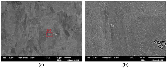
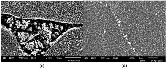
Figure 8.
Scanning electron microscopy after chemical etching of Inconel 718 sample obtained by Laser Powder Bed Fusion (PBF-LB) and solubilized at 1095 °C for 1 h, presenting (a) columnar grains, (b) grain contour with precipitated phases, (c) interior of the lack of fusion defect, and (d) precipitated phases.
Figure 8c shows a high magnification of the interior of a “lack of fusion” defect, illustrating the internal topography of the cavity. In this specific region, no free or partially melted powder particles were identified. However, the absence of these particles may be related to metallographic preparation steps, such as sanding or polishing, which may have removed particles weakly adhered to the matrix. Figure 8d shows in greater detail the presence of precipitated phases in the grain contours, revealed after chemical etching.
The microstructure obtained after the heat treatment of solution followed by double aging (Figure 9) reveals the maintenance of the columnar morphology of the grains, characteristic of the PBF-LB process. Note the presence of twins, along with more defined grain contours than in the only solubilized condition. The formation of twins in IN718 is generally associated with fine equiaxed grains, typical of alloys processed by conventional routes, and is unusual in materials produced by PBF-LB in the as-built condition. However, Tucho et al. [23] highlights that twins can form during solution heat treatment, depending on the applied temperature and time conditions.
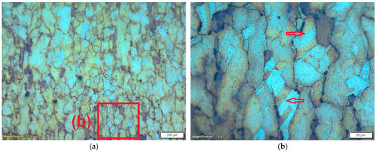
Figure 9.
Microscopy of the Inconel 718 sample obtained by Laser Powder Bed Fusion (PBF-LB) + solution and double aging after chemical etching. (a) General micrograph and (b) detail showing twins in columnar profile grains (red arrows).
In addition, although not directly stated, Švec et al. [24] suggest that chemical etching applied after heat treatment can alter the contrast of the microstructure, facilitating the development of twins and grain contours. Thermally induced changes in the distribution of secondary phases affect how the reagent interacts with the sample surface, by enhancing the contrast between matrix regions and their contours. Thus, the increased visibility of the twins in the doubly aged condition may not indicate an actual increase in their numbers, but rather a variation in the chemical response arising from the precipitation of phases during aging. Therefore, the clearest evidence of the twins and grain contours can be attributed to a combination of the microstructural evolution promoted by the heat treatment and the selective action of the chemical etching.
Figure 10 illustrates the microstructure of the IN718 sample obtained by forging and rolling, after heat treatment of solution at 1095 °C for 1 h, followed by double aging. Comparing this micrograph with Figure 9a, which corresponds to the same thermal sequence applied to the sample produced by PBF-LB, makes the difference between the resulting grain profiles evident. The sample of the forged and rolled IN718 displays equiaxed grains, distributed relatively evenly, which is expected considering the condition analyzed. The sample obtained by PBF-LB preserves the columnar structure inherited from solidification. In addition, Figure 10 exhibits more twins inside the equiaxed grains, indicated by red arrows. This contrast with the PBF-LB sample, where the occurrence of twins was scarce, reinforces the role of granular morphology in the easy formation and development of these characteristic traits. The combination of wider equiaxed grains and the microstructural uniformity typical of the forged and rolled IN718 often leads to the formation of twins, which become more visible after chemical etching. Thus, this comparison illustrates how the processing history directly influences the microstructural characteristics, even under the same heat treatment conditions.
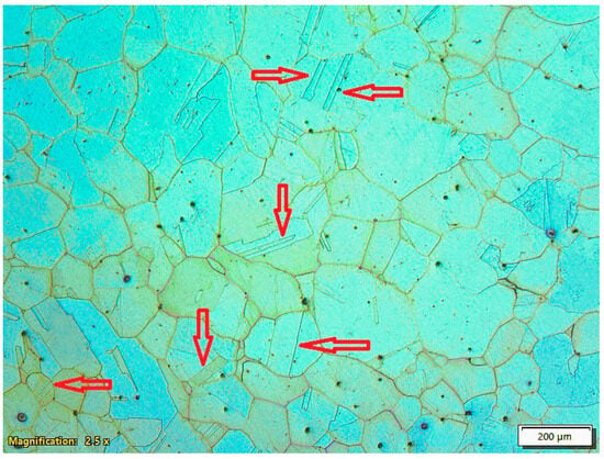
Figure 10.
Sample microscopy of the forged and rolled Inconel 718 after heat treatment of solution at 1095 °C for 1 h, followed by double aging equiaxed grains, with twins indicated by red arrows.
Figure 11 contains X-ray diffractograms of the IN718 samples obtained by PBF-LB solubilized at 1095 °C for 1 h (AM-S), solubilized at 1095 °C for 1 h and double aging (AM-S-DA), as well as the sample obtained by forging and rolling, solubilized at 1095 °C for 1 h, and double aging (FR-S-DA). X-ray diffraction analyses performed for all IN718 samples (AM-S, AM-S-DA, and FR-S-DA) revealed the predominant presence of the γ phase, evidenced by the peaks corresponding to the diffractions of the crystallographic planes (111), (200), and (220), characteristic of the face-centered cubic (fcc) crystal structure of IN718. No additional peaks associated with δ or Laves phases were detected. However, it is important to know that the XRD is a bulk-averaged technique, and its practical detection of minor phases can be limited when the phase fraction is low, the precipitates are very fine and localized (e.g., grain boundaries/interdendritic regions), and/or peaks of secondaries phases overlap with the intense γ-matrix peaks. Therefore, the absence of detectable δ/Laves peaks does not exclude the presence of small residual amounts observed locally by SEM.
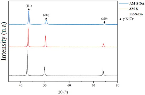
Figure 11.
X-ray diffractograms of Inconel 718 samples obtained by Laser Powder Bed Fusion (PBF-LB), solubilized at 1095 °C for 1 h (AM-S), solubilized at 1095 °C for 1 h and double aging (AM-S-DA), and obtained by forging and rolling, solubilized at 1095 °C for 1 h and double aging (FR-S-DA).
The lack of peaks for the γ′-Ni3Al and γ″-Ni3Nb phases is consistent with the fact that both precipitate coherently for the γ matrix, sharing the same crystallographic orientation. As a result, the γ′ and γ″ precipitates do not generate additional peaks but help increase the intensity and width of the γ phase peaks, especially in the planes {111}, where precipitation is energetically favored. In addition, hardening precipitates have a very low volumetric fraction, making it difficult to detect by X-ray diffraction. The sample processed by forging and rolling, solubilized, and doubly aged (FR-S-DA) specifically exhibits a low intensity peak around 2θ ≈ 40°, which can be attributed to the formation of niobium-rich carbides (NbCs), commonly present in IN718 after prolonged exposure at elevated temperatures. Although slight, the presence of these and other carbides can impact ductility and corrosion resistance under certain service conditions, as observed in other studies [21,25].
The Vickers microhardnesses, presented in Table 3, are in line with expectations, indicating the effectiveness of the applied heat treatments. The sample produced by PBF-LB and subjected only to solution had the lowest microhardness value, suggesting the dissolution of the hardening phases present in IN718, both desired and undesired. The sample aged at 720 °C (AM-S-A720) presented greater microhardness than that aged at 620 °C (AM-S-A620). This difference can be attributed to the greater formation of the γ″ phase, which is mainly responsible for the hardening of IN718, in aging at 720 °C, while aging at 620 °C favors the precipitation of the γ′ phase, which has a lower contribution to hardening. The samples submitted to double aging (AM-S-DA and FR-S-DA) exhibited the highest microhardness values, especially the AM-S-DA sample, which obtained a microhardness value of 481 ± 8 HV. The greater microhardness of the AM-S-DA sample than the FR-S-DA may be due to the differences in the precipitated phases and microstructural profile from the PBF-LB process, which tends to produce more refined and homogeneous microstructures.
Table 3.
Vickers microhardness measurements of Inconel 718 samples obtained by Laser Powder Bed Fusion (PBF-LB) under solubilized (AM-S) and aged conditions (AM-S-A720, AM-S-A620, and AM-S-DA), and by forging and rolling under double aging (FR-S-DA).
3.3. Fatigue Tests and S–N Curves
Uniaxial tensile tests were performed on IN718 to determine the tensile strength of the samples obtained by PBF-LB or forging and rolling. The average tensile strength values were 1424 MPa and 1209 MPa, for the IN718 specimens obtained by PBF-LB and by forging and rolling, respectively. The superior tensile strength of samples manufactured by PBF-LB, solubilized at 1095 °C for 1 h, and double aging (AM-S-DA) compared to that obtained by forging and rolling, solubilized at 1095 °C for 1 h, and double aging (FR-S-DA) was also observed in the study by Nicoletto [26]. This author attributed this superiority to the typical columnar microstructure of the pieces obtained by PBF-LB because this method promotes preferential orientation and lower density of critical defects. The higher tensile strength of the IN718 specimens in the AM-S-DA condition is consistent with their higher microhardness values, as previously noted.
These references obtained in the tensile tests were employed to define the stress levels applied in the fatigue tests of the specimens. Fatigue tests were performed on specimens manufactured by PBF-LB and by forging and rolling, both subjected to solution and double aging heat treatments. Fatigue tests were conducted until fracture or until the interruption of the test at cycles. Figure 11 presents the curves for stress—number of cycles to failure (S–N) of the IN718 specimens obtained by PBF-LB and by forging and rolling, both solubilized at 1095 °C/1 h and double aged at 720 °C/8 h and at 620 °C/8 h. However, despite the higher tensile strength of IN718 obtained by PBF-LB, its fatigue performance was worse, with IN718 obtained by forging and rolling performing better.
Figure 12a shows that the IN718 obtained by forging and rolling presented a fatigue life systematically superior to that manufactured by Laser Fusion in Powder Bed (PBF-LB). In the tests of the IN718 manufactured by forging and rolling, with stresses applied at 360 MPa fatigue, the two specimens did not break by 1,000,000 cycles (run-out), and the tests were interrupted as indicated with arrows on the graph. For the tests with high stresses, the difference was smaller, consistent with the results of the tensile tests, which found superior tensile strength for the specimens manufactured by PBF-LB. With decreased fatigue, the IN718 manufactured by forging and rolling exhibits increasingly better performance than that obtained by PBF-LB. For example, at stresses close to 600 MPa, the specimens obtained by PBF-LB withstood on the order of 40,000 cycles until breaking, while those manufactured by forging and rolling reached 300,000.
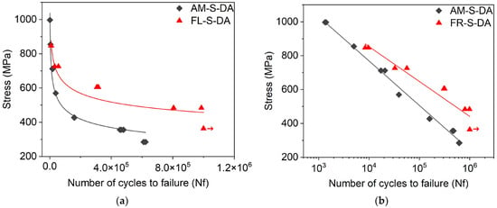
Figure 12.
S–N curves of 718 Inconel manufactured by Laser Powder Bed Fusion (PBF-LB) (AM-S-DA) and by forging and rolling (FR-S-DA), solubilized at 1095 °C/1 h and double aged at 720 °C/8 h and 620 °C/8 h. Number of scaled cycles: (a) normal and (b) logarithmic.
Figure 12b shows the S–N curves on a log scale. In this figure, the line referring to IN718 in the forged and rolled condition has a lower slope than that manufactured by PBF-LB, suggesting a more efficient resistance to nucleation and propagation of fatigue cracks. This difference may be related to the porosity, orientation of columnar grains, and possible residual stress remaining in IN718 obtained by PBF-LB. These results are reasonable as the IN718 produced by forging and rolling generally exhibits better fatigue performance, especially in high-cycle regimes. The study by Pei et al. [26] found that the material manufactured by PBF-LB presents worse fatigue performance and deterioration of the fatigue crack growth behavior due to inhomogeneous microstructures and “lack of fusion” defects from the additive process. The study argues that IN718 obtained by PBF-LB generally exhibits lower fatigue strength than forged and rolled material and that the difference becomes more significant in the high-cycle regime. Song et al. [25] focused on the behavior in very high cycle fatigue (VHCF). This study demonstrated that in the VHCF regimen (over 108 cycles), the forged IN718 exhibited slightly better fatigue strength than the alloy obtained by PBF-LB. The study attributes the initiation of fatigue cracks in the VHCF regime to internal defects, such as “lack of fusion,” microstructural inclusions and discontinuities in the material, indicating a dominant failure mechanism by these defects and by the microstructure in this VHCF regime.
The defects and anisotropy of the IN718 obtained by PBF-LB cause significant data dispersion and inferior performance to fatigue, compared to the fatigue of the forged and rolled IN718. Although porosity was not quantified in terms of volume fraction or pore size distribution, the fatigue results provide quantitative evidence of its influence. At comparable stress levels, specimens manufactured by PBF-LB exhibit shorter fatigue life, while forged and rolled specimens reached run-out (red arrows) conditions at low stress amplitudes. This difference in fatigue response quantitatively reflects the greater severity and criticality of process-related defects in the PBF-LB manufactured material.
Defects induced on the IN718 obtained by PBF-LB should be minimized for materials with fatigue loading applications, by optimizing process parameters and/or by suitable subsequent processing, such as hot isostatic pressing (HIP). HIP is used to eliminate most pores of materials manufactured by PBF-LB by applying isostatic pressure at elevated temperatures. Heat treatment techniques, such as solution and aging, are used to improve the microstructure of IN718 obtained by PBF-LB by dissolving brittle particles in the microstructure and precipitating reinforcement phases. Material removal processes such as machining and polishing are used to improve the surface finish of surfaces manufactured by PBF-LB. In the absence of an HIP step, the machining process also removes regions of highly dense porosity at the periphery of components manufactured by PBF-LB.
3.4. Fracture Surfaces of Fatigue Test Specimens
Figure 13, Figure 14 and Figure 15 show the fracture surfaces of the IN718 specimens obtained by PBF-LB and by forging and rolling, both solubilized at 1095 °C/1 h and double-aged at 720 °C/8 h and at 620 °C/8 h and tested in fatigue. The fracture surface of an IN718 specimen manufactured by PBF-LB and subjected to double aging (AM-S-DA condition), in Figure 13a, exhibits regions of fatigue fracture: crack nucleation, stable propagation, and final rupture. In the lower right of the image, a large defect is obvious near the nucleation of the crack zone. The magnification of this defect, observed in Figure 13b, shows that the interior of the cavity contains unfused and partially fused spherical particles, with diameters greater than 19 µm, which classify it as a typical incomplete fusion gap or lack of fusion, a defect intrinsic to the process of PBF-LB. This type of imperfection acts as a stress concentrator and can significantly reduce fatigue life, especially in regimes with a high number of cycles.
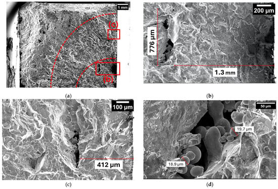
Figure 13.
Fracture surface of an Inconel 718 specimen manufactured by Laser Powder Bed Fusion (PBF-LB) and subjected to double aging (AM-S-DA condition). (a) Overview and regions of the beginning and propagation of cracking and rupture by mechanical overload. (b) There is a major defect in the area where the crack started. (c) Small defect near the surface of the specimen. (d) Free and partially fused powder particles within the defect.
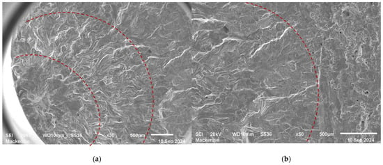
Figure 14.
Fracture surface of the specimen of Inconel 718 manufactured by forging and rolling, solubilized and double aging (FR-S-DA), presenting in (a) an overview and regions of crack initiation and propagation, and in (b) a transition between the region of crack propagation and final rupture by mechanical overload (dotted red line).
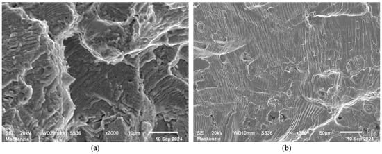
Figure 15.
Fracture surfaces showing fatigue striations in Inconel 718 obtained by (a) Laser Powder Bed Fusion (PBF-LB) and by (b) forging and rolling, both resulting from mid-level applied stress values (427.20–483.77 MPa).
Figure 13c illustrates a second, smaller defect located close to the surface of the specimen. Although smaller, its proximity to the surface makes it particularly critical as it can facilitate crack nucleation under cyclic loading. Figure 13d shows details of the morphology of these particles, with sizes ranging between approximately 18.9 µm and 19.7 µm, compatible with the granulometry of the metallic powder used in the process. The presence of partially fused particles indicates inadequate volumetric energy parameters during PBF-LB, compromising complete coalescence between adjacent layers.
Defects located in the vicinity of the crack nucleation on fracture surfaces of IN718 specimens manufactured by PBF-LB have been widely reported in the literature. Sanchez-Camargo et al. [27], for example, performed detailed measurements of the projected area of these defects, especially those classified as superficial fusion gaps located in the critical nucleation region of the fatigue crack. Spherical particles of unfused and partially fused powder can remain inside the defect and are typical characteristics of coalescence failures during the laser melting process. These imperfections function as stress concentrators and can significantly reduce fatigue life, especially under high-cycle loading regimes.
The fracture surface of the specimen of 718 Inconel manufactured by forging and rolling, solubilized and double aging (FR-S-DA), presented in Figure 14a, reveals a characteristic transgranular fracture profile of fatigue failure under uniaxial loading with load ratio R = −1. The three typical regions of the fatigue fracture process—the region of nucleation of the crack, the region of stable propagation, and the region of final rupture—can clearly be identified. Figure 14b shows an enlargement of the transition zone between the crack propagation region and the final fracture. This region exhibits aspects of ductile fracture, evidenced by the presence of dimples associated with plastic deformation, with final collapse of the material after the progressive growth of the fatigue crack.
The comparison between the fracture surfaces of the IN718 specimens from the different processing methods reveals significant differences in fatigue behavior. In the sample obtained by PBF-LB, observed in Figure 13a, a relatively extensive fragile fracture region is obvious, occupying more than half of the fracture surface area. This characteristic suggests a lower resistance to final fracture after crack propagation. In addition, the manufacturing defects revealed on the surface can act as preferred sites for crack nucleation. In contrast, the sample processed by forging and rolling, shown in Figure 14b, exhibits a region with more extensive crack propagation and a much smaller final rupture zone, indicating superior performance for fatigue strength. Considering that both samples were subjected to average stress levels (427.20–483.77 MPa), the results are consistent with the S–N curves in Figure 12, in which the specimen of the forged and rolled IN718 has a fatigue life up to 25 times greater than that of the specimen obtained by PBF-LB for average stresses.
The fatigue life reported in the S–N curves correlates with the fracture surface observations, where crack initiation in PBF-LB specimens was consistently associated with lack-of-fusion pores and process-induced defects, whereas forged and rolled specimens exhibited fewer critical defects acting as crack initiation sites.
This superior performance can be attributed not only to the absence of critical defects but also to the higher ultimate fracture strength of the IN718 manufactured by forging and rolling. The reduced extent of the rupture region and the prevalence of stable crack propagation indicate a more homogeneous microstructure and resistance to brittle fracture. Additionally, the crack propagation mechanisms were analyzed based on the presence of fatigue streaks, as evidenced in Figure 15. Figure 15a shows the specimen fracture surface of IN718 obtained by PBF-LB, with short and discontinuous fatigue striation, suggesting more unstable crack front behavior. In contrast, Figure 15b, corresponding to the fracture surface of an IN718 specimen obtained by forging and rolling, exhibits longer and more continuous splines, characteristic of a more regular and stable crack propagation. These morphological differences in fatigue striations indicate a direct influence of the microstructure on the dynamics of crack propagation. The greater extent of the striations on the fracture surfaces of the IN718 specimens obtained by forging and rolling can be associated with their more homogeneous microstructure, for both phase distribution and grain morphology. The specimens obtained by PBF-LB, due to microstructural heterogeneity and the presence of porosity and partially fused particles, exhibit more frequent interruptions in the crack propagation, reflected in the segmented striations.
It should be noted that the statistical occurrence rates of the defects acting as crack nucleators were not determined. The fractographic analysis presented here is qualitative and representative of the observed failure mechanisms.
4. Conclusions
- (1)
- Compared to the Inconel 718 obtained by Laser Powder Bed Fusion (PBF-LB), solubilized and double aged, and the forged and rolled, also solubilized and double aged, the apparent pores and pore size are greater for samples processed by PBF-LB. The greater presence of defects identified in Inconel 718 obtained by PBF-LB reduces fatigue life due to its susceptibility to crack nucleation. The apparent amount of twins is higher for the Inconel 718 processed by forging and rolling.
- (2)
- Although IN718 produced by PBF-LB exhibited higher microhardness and tensile strength compared to forged and rolled materials, this improvement did not translate into better fatigue performance. Specimens obtained by PBF-LB, when compared to forged and rolled specimens, showed shorter fatigue life, particularly in the high-cycle fatigue regime. This contrast indicates that the fatigue behavior of IN718 produced by PBF-LB is more strongly influenced by microstructural characteristics and process-related defects, such as lack-of-fusion pores, defect morphology, and columnar grain orientation, than by strength or hardness alone.
- (3)
- The shorter fatigue life of Inconel 718 by PBF-LB is not attenuated by solution and double aging heat treatments. The typical defects of Inconel 718 obtained by PBF-LB contribute to the nucleation of fatigue-generated cracks. After the crack nucleation, the defects that involve large voids of material, such as gaps and “keyholes,” promote the nucleation and subsequent propagation of the cracks.
- (4)
- The predominance of the rupture region for Inconel 718 manufactured by PBF-LB, solubilized at 1095 °C for 1 h + aging at 720 °C for 8 h + aging at 620 °C for 8 h remains even for medium percentage stresses of the maximum tensile strength. However, the forged and rolled Inconel 718, even at higher levels, presents a decrease in the final rupture region.
Author Contributions
Conceptualization, R.E.C. and A.A.C.; methodology, R.E.C. and A.A.C.; software, R.E.C.; validation, M.M., L.R. and R.L.P.G.; formal analysis, R.E.C. and L.R.; investigation, R.E.C.; resources, A.A.C. and M.M.; data curation, R.E.C., G.d.L.X.R. and R.L.P.G.; writing—original draft preparation, A.A.C. and R.E.C.; writing—review and editing, G.d.L.X.R.; visualization, A.A.C.; supervision, A.A.C.; project administration, A.A.C.; funding acquisition, A.A.C. All authors have read and agreed to the published version of the manuscript.
Funding
The authors are thankful for the funding provided by the MackPesquisa project 251031 and Innovation Fund and the National Council for Scientific and Technological Development (CNPq-Brazil), under grant number 407050/2023-0 and 306559/2024-2.
Data Availability Statement
The original contributions presented in this study are included in the article. Further inquiries can be directed to the corresponding authors.
Acknowledgments
The author Luís Reis acknowledge Fundação para a Ciência e a Tecnologia (FCT) for its financial support via LAETA (project https://doi.org/10.54499/UID/50022/2025).
Conflicts of Interest
The authors declare no conflicts of interest.
Abbreviations
The following abbreviations are used in this manuscript:
| IN718 | Inconel 718 nickel alloy |
| PBF-LB | Laser Powder Bed Fusion |
| AM | Additive Manufacturing |
| S–N | Stress vs. Number of cycles curve |
References
- Mostafaei, A.; Ghiaasiaan, R.; Ho, I.-T.; Strayer, S.; Chang, K.-C.; Shamsaei, N.; Shao, S.; Paul, S.; Yeh, A.-C.; Tin, S.; et al. Additive Manufacturing of Nickel-Based Superalloys: A State-of-the-Art Review on Process-Structure-Defect-Property Relationship. Prog. Mater. Sci. 2023, 136, 101108. [Google Scholar] [CrossRef]
- Haines, M.P.; Rielli, V.V.; Primig, S.; Haghdadi, N. Powder Bed Fusion Additive Manufacturing of Ni-Based Superalloys: A Review of the Main Microstructural Constituents and Characterization Techniques. J. Mater. Sci. 2022, 57, 14135–14187. [Google Scholar] [CrossRef]
- Kwabena Adomako, N.; Haghdadi, N.; Primig, S. Electron and Laser-Based Additive Manufacturing of Ni-Based Superalloys: A Review of Heterogeneities in Microstructure and Mechanical Properties. Mater. Des. 2022, 223, 111245. [Google Scholar] [CrossRef]
- Deng, D.; Peng, R.L.; Brodin, H.; Moverare, J. Microstructure and Mechanical Properties of Inconel 718 Produced by Selective Laser Melting: Sample Orientation Dependence and Effects of Post Heat Treatments. Mater. Sci. Eng. A 2018, 713, 294–306. [Google Scholar] [CrossRef]
- Zhou, L.; Mehta, A.; Mcwilliams, B.; Cho, K.; Sohn, Y. Microstructure, Precipitates and Mechanical Properties of Powder Bed Fused Inconel 718 before and after Heat Treatment. J. Mater. Sci. Technol. 2018, 35, 1153–1164. [Google Scholar] [CrossRef]
- Mostafa, A.; Rubio, I.P.; Brailovski, V.; Jahazi, M.; Medraj, M. Structure, Texture and Phases in 3D Printed IN718 Alloy Subjected to Homogenization and HIP Treatments. Metals 2017, 7, 196. [Google Scholar] [CrossRef]
- Liu, H.; Cheng, W.; Sun, Y.; Ma, R.; Wang, Y.; Bai, J.; Xue, L.; Song, X.; Tan, C. Effects of Process Parameters and Heat Treatment on Microstructure and Mechanical Characteristics of Laser Powder Bed Fusion Alloy Inconel 718. Coatings 2023, 13, 189. [Google Scholar] [CrossRef]
- King, W.E.; Barth, H.D.; Castillo, V.M.; Gallegos, G.F.; Gibbs, J.W.; Hahn, D.E.; Kamath, C.; Rubenchik, A.M. Observation of Keyhole-Mode Laser Melting in Laser Powder-Bed Fusion Additive Manufacturing. J. Mater. Process. Technol. 2014, 214, 2915–2925. [Google Scholar] [CrossRef]
- Zhao, C.; Shi, B.; Chen, S.; Du, D.; Sun, T.; Simonds, B.J.; Fezzaa, K.; Rollett, A.D. Laser Melting Modes in Metal Powder Bed Fusion Additive Manufacturing. Rev. Mod. Phys. 2022, 94, 045002. [Google Scholar] [CrossRef]
- Watring, D.S.; Benzing, J.T.; Hrabe, N.; Spear, A.D. Effects of Laser-Energy Density and Build Orientation on the Structure-Property Relationships in as-Built Inconel 718 Manufactured by Laser Powder Bed Fusion. Addit. Manuf. 2020, 36, 101425. [Google Scholar] [CrossRef]
- Gruber, K.; Stopyra, W.; Kobiela, K.; Kohlwes, P.; Čapek, J.; Polatidis, E.; Kelbassa, I. Achieving High Strength and Ductility in Inconel 718: Tailoring Grain Structure through Micron-Sized Carbide Additives in PBF-LB/M Additive Manufacturing. Virtual Phys. Prototyp. 2024, 19, e2396064. [Google Scholar] [CrossRef]
- Debroy, T.; Wei, H.L.; Zuback, J.S.; Mukherjee, T.; Elmer, J.W.; Milewski, J.O.; Beese, A.M.; Wilson-Heid, A.; De, A.; Zhang, W. Additive Manufacturing of Metallic Components—Process, Structure and Properties. Prog. Mater. Sci. 2017, 92, 112–224. [Google Scholar] [CrossRef]
- Radhakrishnan, J.; Kumar, P.; Li, S.; Zhao, Y.; Ramamurty, U. Unnotched Fatigue of Inconel 718 Produced by Laser Beam-Powder Bed Fusion at 25 and 600 °C. Acta Mater. 2022, 225, 117565. [Google Scholar] [CrossRef]
- Kaletsch, A.; Qin, S.; Herzog, S.; Broeckmann, C. Influence of High Initial Porosity Introduced by Laser Powder Bed Fusion on the Fatigue Strength of Inconel 718 after Post-Processing with Hot Isostatic Pressing. Addit. Manuf. 2021, 47, 102331. [Google Scholar] [CrossRef]
- Moussaoui, K.; Rubio, W.; Mousseigne, M.; Sultan, T.; Rezai, F. Effects of Selective Laser Melting Additive Manufacturing Parameters of Inconel 718 on Porosity, Microstructure and Mechanical Properties. Mater. Sci. Eng. A 2018, 735, 182–190. [Google Scholar] [CrossRef]
- ASTM E606/E606M-21.; Standard Test Method for Strain-Controlled Fatigue Testing. ASTM International: West Conshohocken, PA, USA, 2021.
- Kladovasilakis, N.; Charalampous, P.; Tsongas, K.; Kostavelis, I.; Tzovaras, D.; Tzetzis, D. Influence of Selective Laser Melting Additive Manufacturing Parameters in Inconel 718 Superalloy. Materials 2022, 15, 1362. [Google Scholar] [CrossRef]
- Borisov, E.; Popovich, A.; Sufiiarov, V. Modification of Inconel 718 Properties by In Situ Y Addition in Selective Laser Melting. Materials 2022, 15, 6219. [Google Scholar] [CrossRef]
- Park, E.; Kim, D.M.; Park, H.W.; Park, Y.B.; Kim, N. Evaluation of Tool Life in the Dry Machining of Inconel 718 Parts from Additive Manufacturing (AM). Int. J. Precis. Eng. Manuf. 2020, 21, 57–65. [Google Scholar] [CrossRef]
- Schneider, J.; Farris, L.; Nolze, G.; Reinsch, S.; Cios, G.; Tokarski, T.; Thompson, S. Microstructure Evolution in Inconel 718 Produced by Powder Bed Fusion Additive Manufacturing. J. Manuf. Mater. Process. 2022, 6, 20. [Google Scholar] [CrossRef]
- Bassini, E.; Marchese, G.; Aversa, A. Tailoring of the Microstructure of Laser Powder Bed Fused Inconel 718 Using solution Annealing and Aging Treatments. Metals 2021, 11, 921. [Google Scholar] [CrossRef]
- Tucho, W.M.; Hansen, V. Studies of Post-Fabrication Heat Treatment of L-PBF-Inconel 718: Effects of Hold Time on Microstructure, Annealing Twins, and Hardness. Metals 2021, 11, 266. [Google Scholar] [CrossRef]
- Botinha, J.; Gehrmann, B.; Alves, H.; Rohwerder, M. Insights into the Localized Corrosion Initiation Mechanisms of Alloy 718. Heliyon 2025, 11, e41754. [Google Scholar] [CrossRef] [PubMed]
- Nicoletto, G. Smooth and Notch Fatigue Behavior of Selectively Laser Melted Inconel 718 with As-Built Surfaces. Int. J. Fatigue 2019, 128, 105211. [Google Scholar] [CrossRef]
- Pei, C.; Shi, D.; Yuan, H.; Li, H. Assessment of Mechanical Properties and Fatigue Performance of a Selective Laser Melted Nickel-Base Superalloy Inconel 718. Mater. Sci. Eng. A 2019, 759, 278–287. [Google Scholar] [CrossRef]
- Song, Z.; Gao, W.; Wang, D.; Wu, Z.; Yan, M.; Huang, L.; Zhang, X. Very-High-Cycle Fatigue Behavior of Inconel 718 Alloy Fabricated by Selective Laser Melting at Elevated Temperature. Materials 2021, 14, 1001. [Google Scholar] [CrossRef]
- Sanchez-Camargo, C.M.; Nadot, Y.; Cormier, J.; Lefebvre, F.; Kan, W.H.; Chiu, L.N.S.; Li, C.; Huang, A. Role of Defects and Microstructure on the Fatigue Durability of Inconel 718 Obtained by Additive Layer Manufacturing Route. Fatigue Fract. Eng. Mater. Struct. 2023, 46, 4678–4693. [Google Scholar] [CrossRef]
Disclaimer/Publisher’s Note: The statements, opinions and data contained in all publications are solely those of the individual author(s) and contributor(s) and not of MDPI and/or the editor(s). MDPI and/or the editor(s) disclaim responsibility for any injury to people or property resulting from any ideas, methods, instructions or products referred to in the content. |
© 2026 by the authors. Licensee MDPI, Basel, Switzerland. This article is an open access article distributed under the terms and conditions of the Creative Commons Attribution (CC BY) license.