


Abstract
Laser cutting is used in the production of formed sheet metal components. However, the cyclic load capacity is reduced compared to other subtractive processes. Laser cutting results in a significant loss of fatigue strength; however, thermal joining has its own effect on the cyclic load capacity. Accordingly, brazing causes a significant reduction in the mechanical strength. However, the open question is what consequences a combination of both processes may have on the overall fatigue strength of sheet metals. Laser-cut samples of AISI 304 with and without a brazed-on element were investigated for their microstructure and mechanical properties. The brazing process was found to have an annealing effect on the microstructure. It was further observed that the fatigue behavior of brazed specimens is dominated by inhomogeneities at the surface of the filler metal fillet located in the geometric notch of the brazed joint. Fatigue strength decreased by almost 50% compared to as-cut specimens. As long as no shared diffusion zone is formed between the laser-cut and the brazed joint, the use of laser cutting for the production of such components appears to be reasonable and does not further contribute to the loss of cyclic strength.
1. Introduction
As a versatile tool, lasers have been used in industry and research for many years. The laser cutting of metals, especially, is a widely used process in industry [1]. The advantages of laser cutting are, among other things, high feed rates, flexibility in contour cuts, low heat impact to the material, and integrability into production lines such as robotic systems [2]. The process of laser cutting is based on the local melting of the material and expulsion by a gas jet flowing coaxially to the laser beam [3]. In the process zone, a curved melt film is formed at the cut front, which flows in the direction of the beam exit due to shear stress of the process gas and causes the typical cut edge phenomena of roughness and burr formation [4]. These phenomena represent typical quality aspects in the laser cutting of sheet metal.
Despite the process advantages, laser cutting is often avoided in the production of load-bearing components [5]. The reason for this is the significant decrease in the observed fatigue strength compared to milled or polished edges [6]. The reason for the reduced strength of approx. 50% is a notch effect of the burr and the heat input of the melting process [7].
Nevertheless, laser cutting is being considered for the production of specific formed sheet metal components such as heat exchangers or components of the exhaust systems of automobiles. Frequently, adding elements such as brackets on the components mentioned is realized by means of brazing.
The challenge consists of evaluating the load-bearing capacity of the asymmetrical stretch impediment as a result of the one-sided stiffening by the mentioned element. Many studies have investigated brazed specimens where the joint is loaded directly [8]. However, this load scenario does not correspond to the applications addressed here and is not transferable to the joint connections of a brazed-on element. In contrast, component-like pipe specimens with a brazed-on element were investigated by Baumgartner et al. by means of different loading configurations [9]. They introduced a load into both the base sample and the brazed-on element. They observed that fatigue cracks started in the fillet of the brazed joint and propagated along the filler metal. They also emphasized that the surface condition and internal inhomogeneities have a great influence on the fatigue behavior.
For the implementation of laser cutting in the production process of brazed components, the question arises as to what extent laser cutting and brazing may have a summative effect on the mechanical strength. On the one hand side, it seems possible that changes in the microstructure and the surface integrity from both thermal processes may interfere with each other. On the other hand, one process may dominate fatigue crack initiation due to the formation of increasingly stressful features, superimposing the influence of the other process.
In order to address these questions and to determine whether laser cutting is suitable for the production of sheet metal components with brazed-on elements, application-oriented investigations on AISI 304 sheet metal were carried out. The microstructure and the mechanical properties were analyzed. Particular emphasis was placed on the identification and description of the failure mechanism under cyclic loading.
2. Materials and Methods
2.1. Preparation of Base Specimens
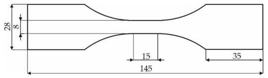
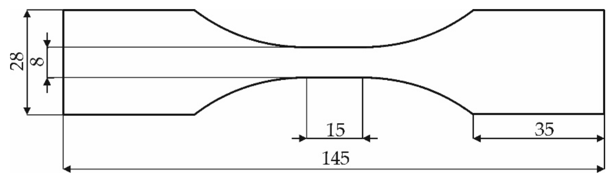
The base specimens for all tests in this study were fabricated from an AISI 304 sheet using laser cutting. Figure 1 shows the specimen geometry. AISI 304 showed pronounced adiabatic heating [10]. The specimen geometry was designed to address this issue considering the high frequencies during fatigue testing (see Section 2.4). The chemical composition and the laser cutting parameters used are listed in Table 1 and Table 2, respectively. In Table 2, fcoll stands for collimation length, ffoc for focal length, dnozzle for nozzle diameter, PL for laser power, vf for feed rate, dz for focal position, ds for stand-off distance, and pgas for gas pressure. The laser cutting parameters were determined in advance by testing a parameter field. The parameter set with the lowest burr formation was selected for the studies presented.
Figure 1.
Specimen geometry manufactured by laser cutting, with dimensions in mm.
Table 1.
Chemical composition of AISI 304 sheet metal used in this work.
Table 2.
Process parameters for laser cutting.
In order to provide a benchmark of the fatigue strength of non-brazed specimens and to evaluate the influence of the brazing process on the cyclic loading capacity, part of the laser-cut specimens was subjected to fatigue testing in the as-cut condition.
2.2. Characterization of Pre-Deformed and Thermally Treated Base Samples
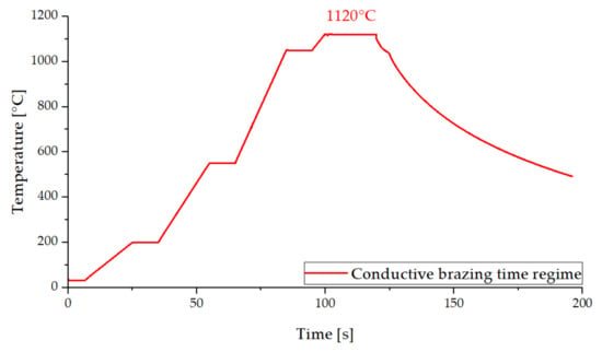
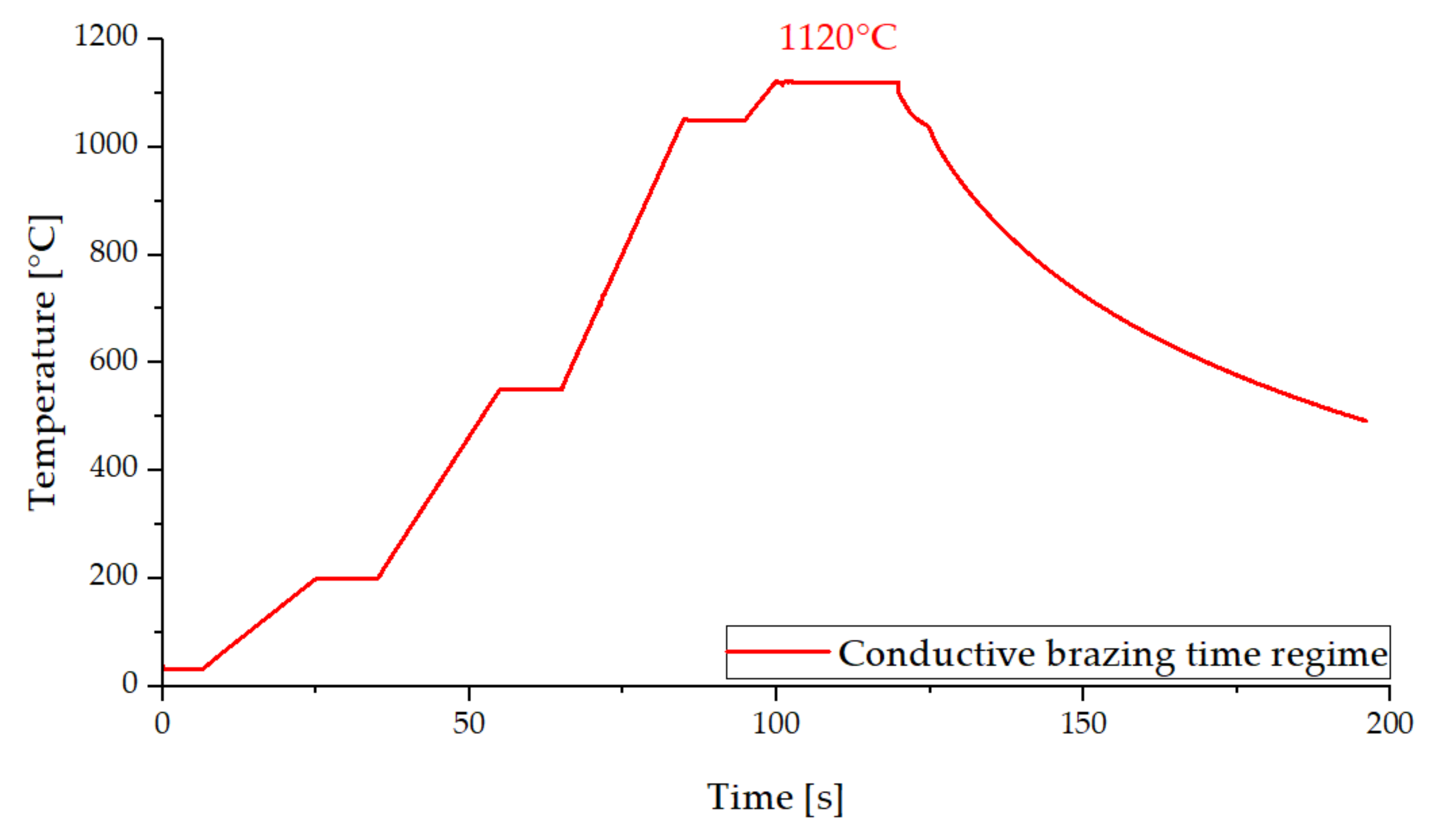
The investigations presented here focused on exploring the applications of formed sheet metal components to which further elements are brazed after forming. Accordingly, in these applications, the formed microstructure is heated by the brazing process, which should lead to annealing effects. The influence of both factors, pre-deformation and a subsequent thermal treatment (mimicking the heat input through the brazing), was analyzed through preliminary tests. For this purpose, laser-processed test samples were pre-deformed to a total strain of 28% by means of a tensile testing machine. The deformation was intended to simulate the forming of the sheet into the component. Afterwards, the brazing process was simulated by means of a specific heat treatment in an oven, replicating the thermal input through the actual conductive brazing process as accurately as possible. The mentioned process of conductive brazing was used for all of the brazed samples in this work, and is presented in detail in Section 2.3. Figure 2 shows the temperature–time curve of brazing in the conductive brazing test stand.
Figure 2.
Temperature–time curve of the conductive brazing process.
As-cut and pre-deformed specimens were heat-treated according to the temperature regime presented in Figure 2. This approach resulted in 4 different specimen conditions:
- As-cut;
- As-cut and heat-treated according to conductive brazing;
- As-cut and subsequently pre-deformed (28% total strain);
- As-cut, subsequently pre-deformed (28% total strain), and finally, heat-treated, mimicking the thermal input through conductive brazing.
The microstructures in all conditions were analyzed. For this purpose, cross-sections were prepared, which were electro-chemically polished and then etched with a mixture of hydrochloric acid, nitric acid, and etching additive. Subsequently, three specimens of each condition were subjected to tensile testing. The specimen geometry shown in Figure 1 was used, which is not a standardized tensile test specimen. Accordingly, the measured values primarily serve as bases for relative comparisons of the different sample statuses, and not so much as design criteria under standard conditions.
2.3. Preparation of Brazed Specimens
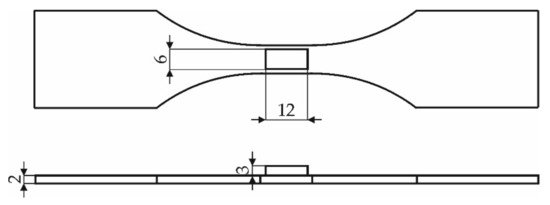
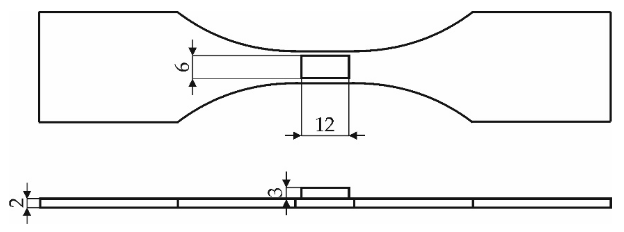
The brazed test sample shape was derived from the base specimen, as described in Section 2.1, and from load-bearing components with a brazed-on local reinforcement (LR). A cuboid piece was brazed onto the surface of the specimens, located in the middle of the sample. The shape enables a direct comparison with the base material properties while displaying typical geometrical details, as given in the applications considered. Detailed geometry of the base specimen with brazed-on LR is depicted in Figure 3.
Figure 3.
Geometry of the base specimen with brazed-on local reinforcement, with dimensions in mm.
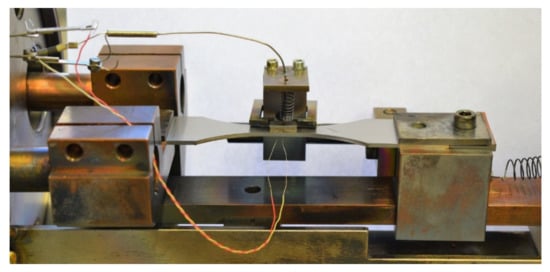
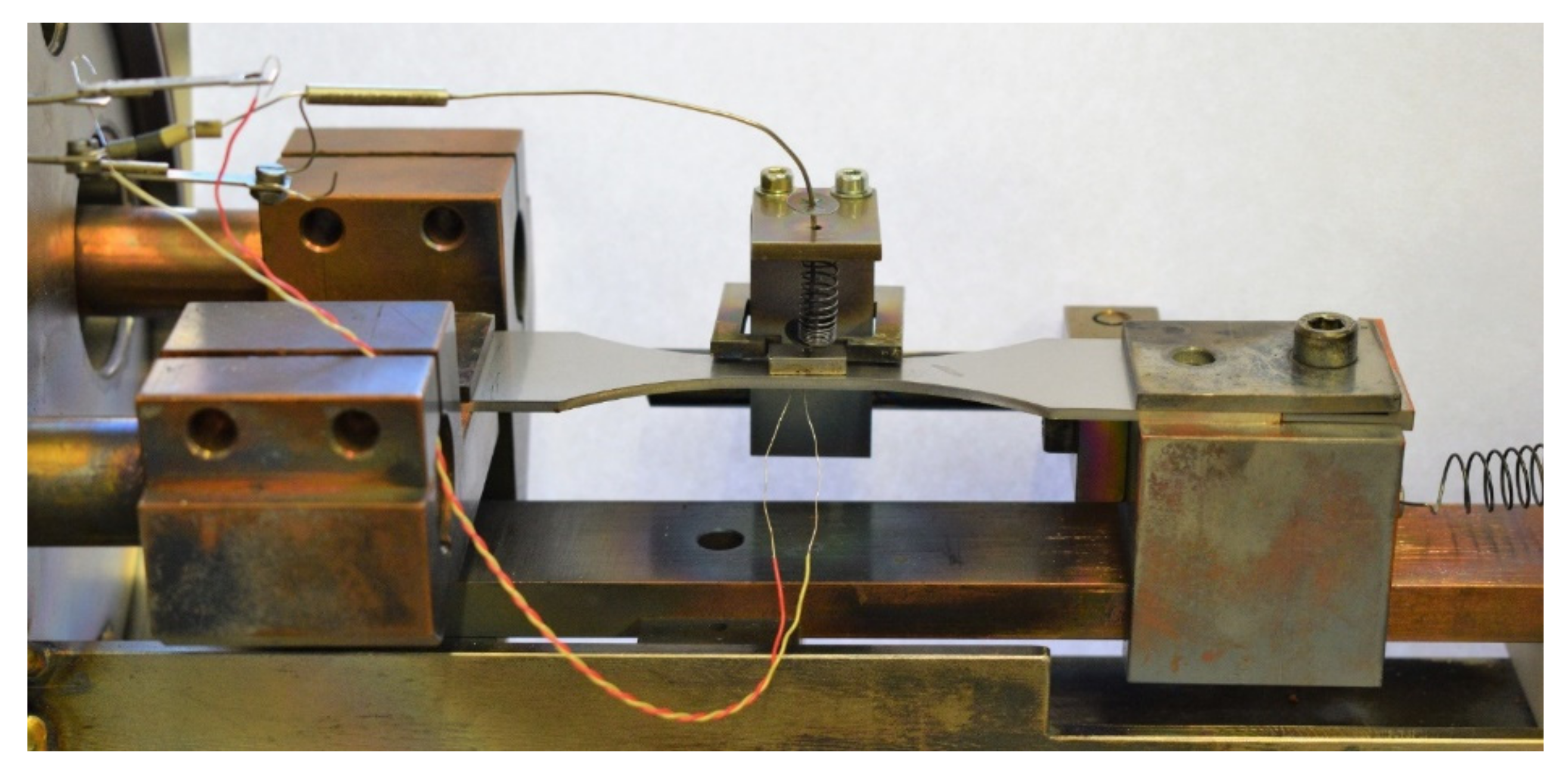
The samples with brazed-on LR were produced by a test stand developed in-house at Technical University Dresden, hereafter called a “conductive test stand”, as shown in Figure 4. This test stand enabled the video documentation of high-temperature brazing processes due to its local heating mechanism. In contrast to industrial vacuum furnaces, this test stand does not require heating a whole vacuum chamber, but rather heats up the test sample alone due to the conductive heating principle applied. As such, test samples are fixed in the test stand by means of two clamps made of copper. An external voltage leads to an electrical current in the sample, and due to the geometric tapering in the middle of the sample, there is an increase in the electrical resistance at this point. In the controlled process, this increased electrical resistance leads to defined heating and enables the brazing process.
Figure 4.
Conductive brazing test stand developed at Technical University Dresden.
The brazing was conducted at high vacuum conditions of 10−4 mbar and at a maximum temperature of 1120 °C. The temperature–time curve is shown in Figure 2. The filler metal was a brazing paste of Ni620, according to ISO 17,672, with a B2 binder provided either by a dosing syringe with a 10% mass proportion of binder or a brazing tape, both prepared and provided by Innobraze GmbH.
2.4. Fatigue Testing
The fatigue testing was carried out on a Gigaforte resonance testing machine from Russenberger Prüfmaschinen AG. This fatigue test system is able to generate test frequencies of approximately 1000 Hz. AISI 304 is known for adiabatic heating during testing at high test frequencies [11]. For the specimen geometry shown in Figure 1, the ratio of the test length to the test cross-section was specifically designed for a best possible application at very high test frequencies. The individual design is based on preliminary investigations focusing the heating tendency of the material. While using the mentioned geometry with the smallest possible test volume, an external cooling with compressed air prevented the material from heating during fatigue testing. The stress ratio, R, was set to 0.1, and the number of load cycles at which a test sample was performed was defined as 108 load cycles. A frequency change, ∆f, of 3 Hz was defined as a stop criterion for testing, indicating technical crack initiation. Fracture surface analyses were performed on failed specimens using scanning electron microscopy (SEM).
3. Results
3.1. Influence of the Brazing Process on Microstructural and Quasi-Static Properties
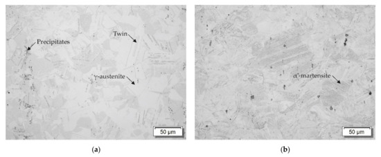
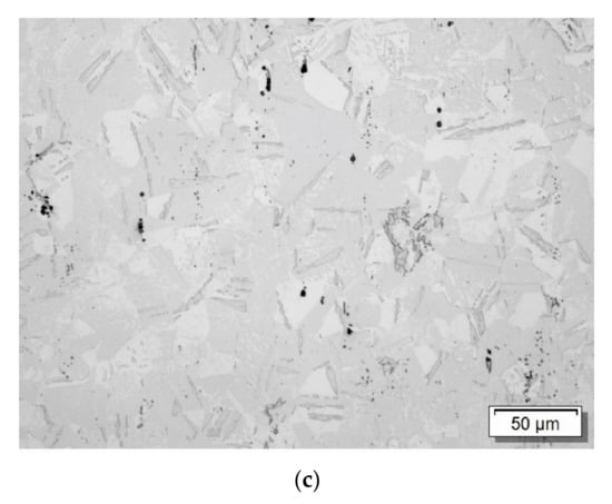
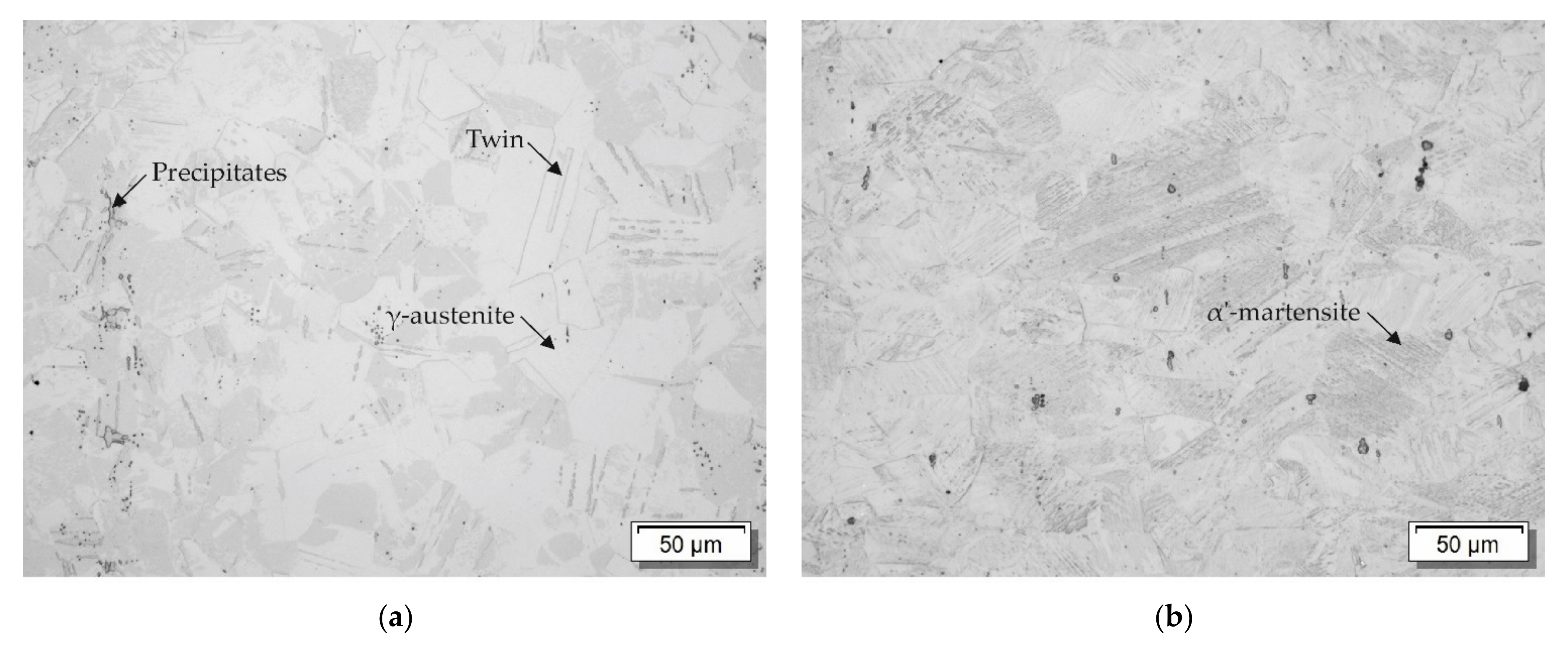
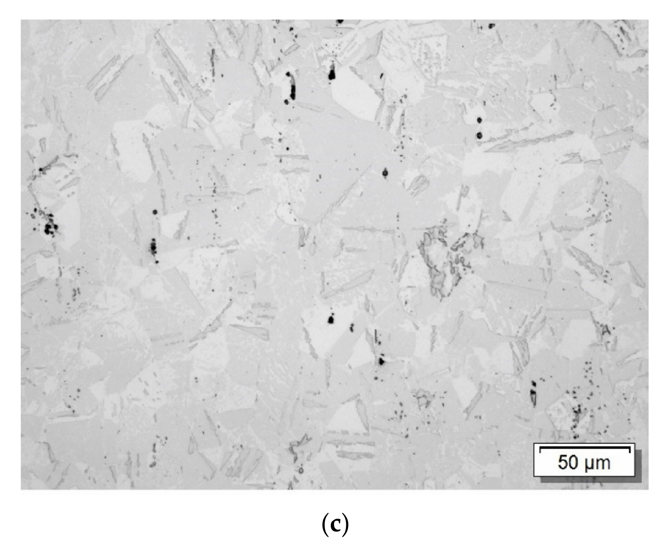
Figure 5 shows the results of the microstructure analysis as part of the preliminary tests. This analysis was performed directly in the middle of the test samples (Figure 1). The presented conditions were as-cut (a), pre-deformed to 28% strain (b), and pre-deformed to 28% strain and heat-treated, simulating the thermal input during conductive brazing (c). The as-cut and heat-treated condition is not explicitly exhibited, because no noticeable difference in microstructure from the as-cut condition was observable.
Figure 5.
Microstructure of specimens investigated in the preliminary tests: (a) as-cut; (b) pre-deformed to a total strain of 28%; (c) pre-deformed to a total strain of 28% and heat-treated in accordance with a conductive brazing temperature regime.
The microstructural analysis showed that the initial as-cut condition had a predominantly austenitic microstructure, with twins and precipitates. As a result of the plastic pre-deformation to 28% total strain at an initial temperature of 22 °C, a deformation-induced phase transformation from γ-austenite to α′-martensite occurred [12]. This material behavior is used in the field of TRIP steels [13]. Measurements with a type MP30 Feritscope from Helmut Fischer GmbH showed an α′-martensite content of 5% to 8%. However, this phase transformation was completely reversed by applying a heat treatment inspired by conductive brazing, which was already expected as per previous investigations [14]. Feritscope measurements showed an α′-martensite content of less than 1% after the treatment. Meanwhile, the very short treatment time resulted in hardly any change in grain size.
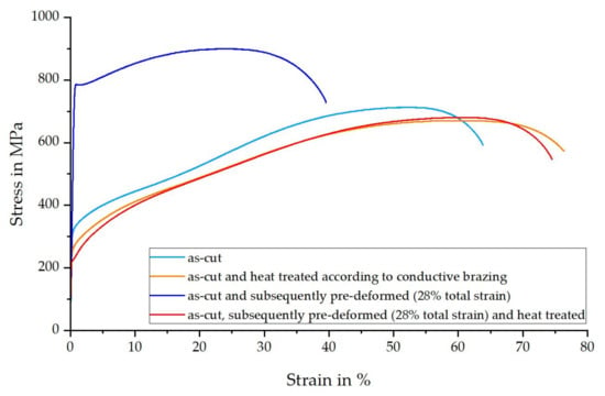
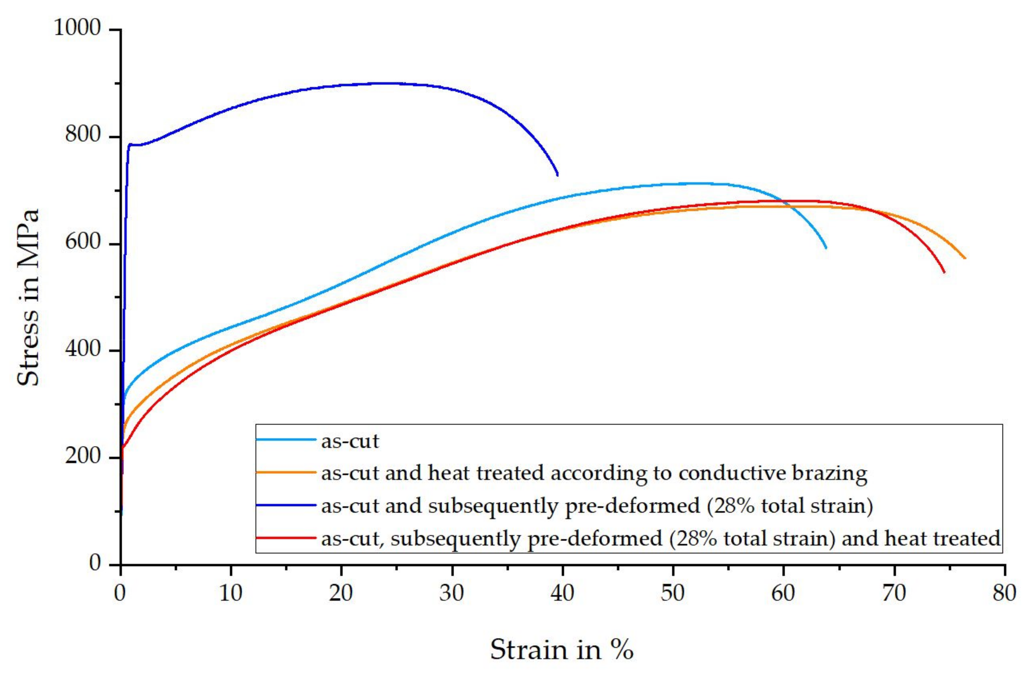
Figure 6 presents the results of the tensile tests. It can be seen that the yield strength of the 28% pre-deformed condition was significantly increased and the elongation at break was significantly reduced, which can be attributed to strain hardening and α′-martensite formation [15]. All other conditions showed almost similar tensile strengths and elongations at break. Five samples of each condition were tested. However, due to the small scatter of the results, only one tensile curve was presented for each condition for ease of visualization. The results suggest that the yield strength of brazed specimens actually decreases. Taking the results of the microstructure analysis into account, it can be stated that the thermal input into the material largely reversed the strengthening effect of the previous forming step, i.e., strain hardening and α′-martensite formation, even though the maximum temperature was only subjected for a few minutes. Consequently, it was assumed that the strengthening effects provoked by an initial forming process were at least in the vicinity of the brazing joint revoked by the thermal input and did not have to be further considered in the test matrix for fatigue testing.
Figure 6.
Stress–strain curves for different processing conditions from preliminary tests prior to fatigue testing.
3.2. Fatigue Behavior of As-Cut and Brazed Specimens
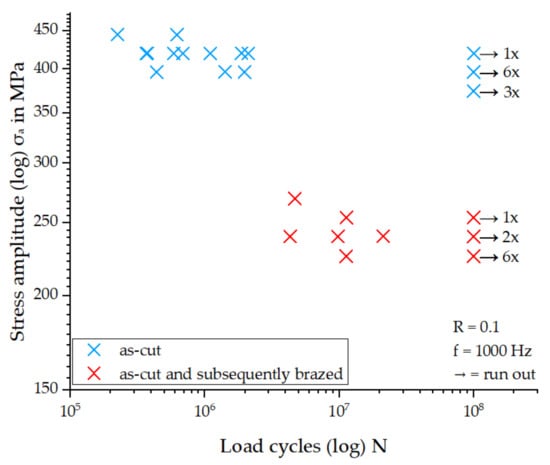
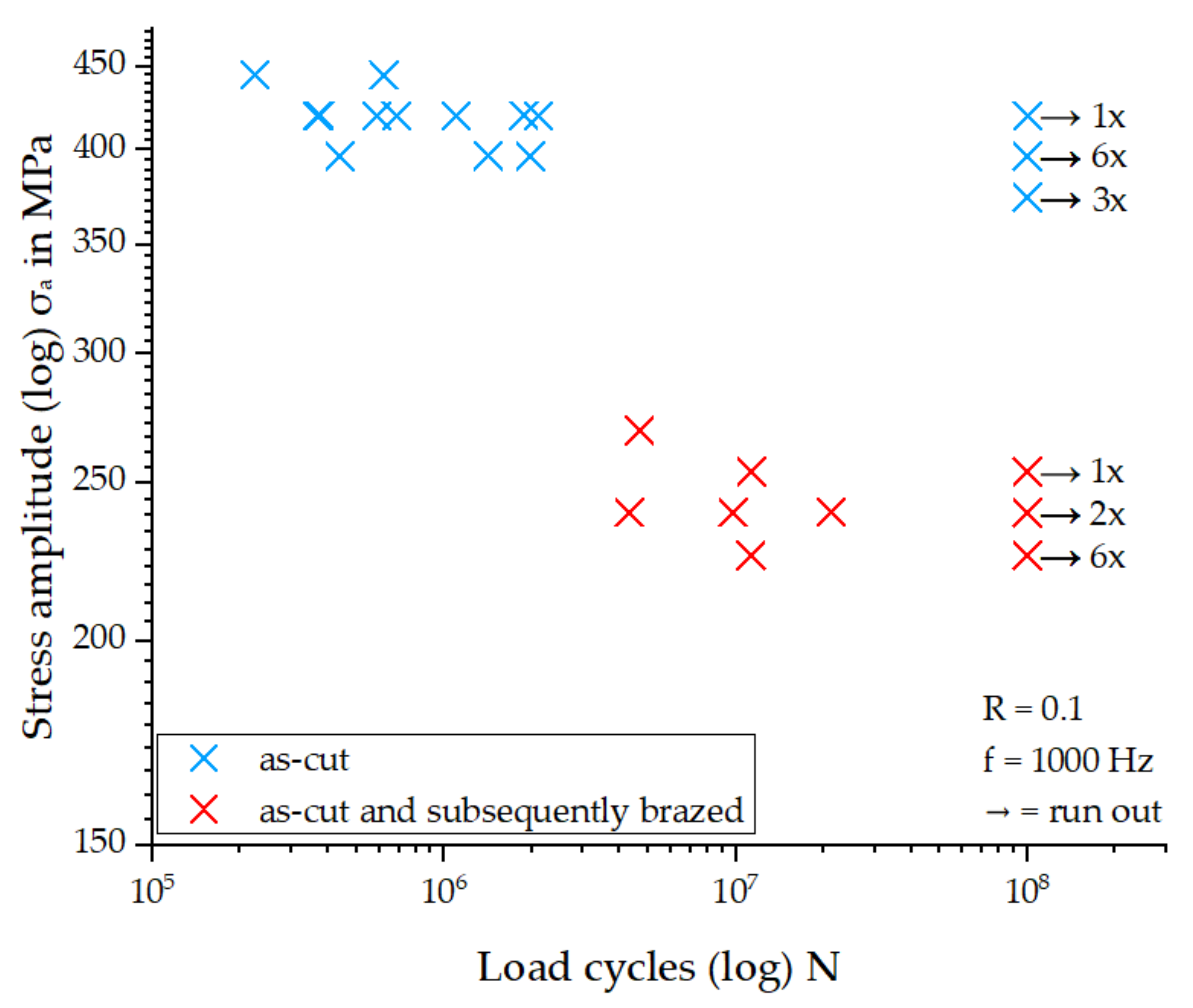
Figure 7 shows the results of the fatigue tests. It can clearly be seen that the specimens in the as-cut condition showed a significantly higher fatigue strength than was the case for specimens with brazed-on LR. Most of the run outs for the as-cut condition were observed at a stress amplitude of 400 MPa, whereas in the case of brazed specimens, it was only 225 MPa.
Figure 7.
Results of the fatigue tests of as-cut and brazed specimens.
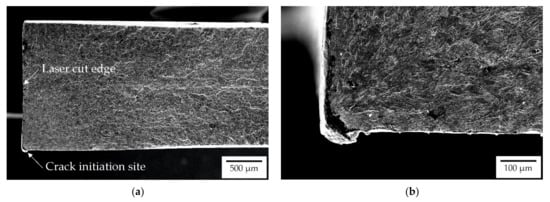
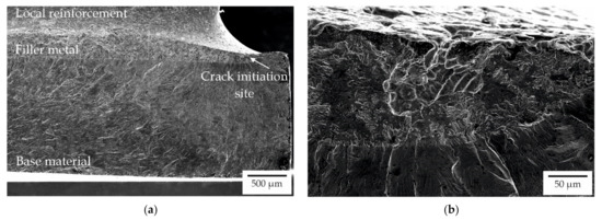
Fatigued samples were subjected to fracture surface analysis by SEM. Figure 8 and Figure 9 show fracture surfaces representative for samples in the as-cut and brazed condition, respectively. For the as-cut specimen, it can be seen that the fatigue crack initiated at the burr and propagated through the material. In the case of the brazed specimens, on the other hand, no specimen failed in relation to the laser-cut edge. Instead, process-related inhomogeneities in the filler metal always led to crack initiation. The brazed connection between base material and LR never failed.
Figure 8.
Fracture surface analysis of an as-cut specimen: (a) overview; (b) crack-initiating site at the burr of the laser-cut edge.
Figure 9.
Fracture surface analysis of a brazed specimen: (a) overview; (b) crack-initiating defect.
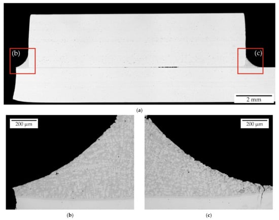
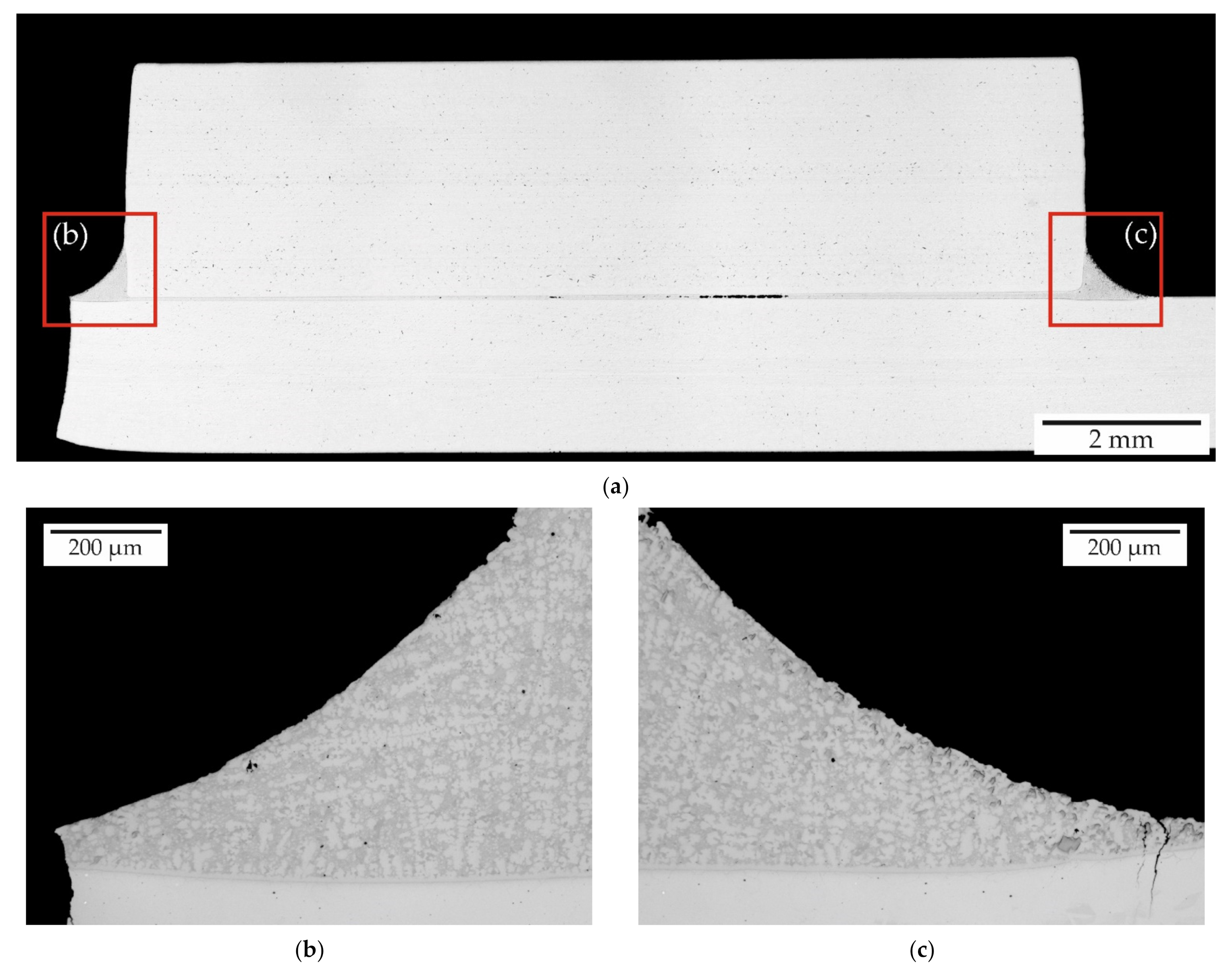
Cross-sections were prepared on selected fractured brazed specimens. This is shown in Figure 10. It was observed that crack initiation started at inhomogeneities positioned in the diffusion zone of the filler metal and the base material. Multiple cracking was also partially observed.
Figure 10.
Cross-section of the brazed joint of a failed specimen: (a) overview; (b) filler metal seam where the failure occurred; (c) filler metal seam featuring crack propagation into the base material.
4. Discussion
In many cases formed sheet metal components are characterized by an increase in strength due to strain hardening, which is realized during forming of the final component geometry. In the case of sheet metal components made of AISI 304, α′-martensite formation leads to further strengthening of the material [16]. However, the preliminary tests on pre-deformed and heat-treated specimens showed that a heat input is typical for thermal joining, with brazing which completely reverses the strengthening effect, both in the microstructural analysis and in the tensile tests. The yield strength in the tensile test tends to be even lower compared to the as-cut condition, the latter already having a negative effect on the mechanical strength on its own. It can be concluded that, consequently, brazing must have a significant influence on the cyclic loading capacity, because the local brazing of elements to the formed component leads to local microstructural changes in the effective area of the brazing joint, which can be compared to annealing effects due to the heat input.
In fact, the fatigue tests showed a decrease in fatigue strength of almost 50% in the case of a brazed-on LR compared to as-cut specimens. Examination of the fracture surfaces revealed significant differences in crack initiation mechanisms. Laser-cut specimens failed at the burr of the laser-cut edge. The heat input of laser cutting led to microstructural changes on the cutting edge of the work piece, and the burr acted as a micro-notch for crack initiation [17]. Therefore, the fatigue behavior in the range of high cycle to very high cycle fatigue is dominated by competition of the different crack initiation mechanisms, i.e., microstructural notch versus geometrical notch.
In the present study, a comparable interaction was observed for brazed specimens. The fracture of the specimens started at inhomogeneities at the surface of the filler metal fillet, where a diffusion zone between the filler metal and base material was formed. A typical fractured surface is shown in Figure 9. The signs at the fractured surface clearly indicate the defect as the cause of failure. It acts as local notch and leads to a microscopic stress concentration where the fatigue crack initiation was located. In some cases, this severe geometrical and metallurgical notch effect even leads to multiple cracking (see Figure 10). However, in contrast to the burr of the laser cut, the interactions between metallurgical and geometrical notches are significantly more pronounced. This results in a heavily reduced cyclic load capacity compared with as-cut specimens.
It should be emphasized at this point that a nickel-based filler metal material was used, which exhibits a higher hardness than stainless-steel base material. To what extent the failure mechanism could change with a filler metal material of similar or even lower hardness than the base material is yet to be investigated. The open question in this respect is whether a more ductile, and hence, more failure-resistant, filler metal material may compensate the coincidence of macroscopic and microscopic notch effect in the brazed joint up to a certain degree.
From the overall observations, it can be concluded that there is no interaction between laser cutting and brazing features in the experimental design conceived for these experiments. However, mutual interaction cannot be ruled out if the filler metal and laser-cut edge form a shared influencing area and diffusion zone. Regarding the use of laser cutting for the production of formed sheet metal parts with brazed-on elements, it can therefore be stated that a laser cutting process can be used without negative effects on the fatigue behavior, as long as brazing does not take place in the immediate vicinity of the laser-cut edge. As long as this is ensured, the cyclic strength of the components is dominated solely by the microstructural and geometric notches of the brazed joint and focus should be on optimizing the process to minimize these effects.
5. Conclusions
Microstructural analysis, tensile and fatigue tests were performed on laser-cut specimens made of AISI 304, partly with brazed-on LR. The test sample design was based closely on the application model of formed sheet metal components with brazed-on elements. The aim of the study was to assess whether laser cutting could be used as a manufacturing method for such components. The investigations led to the following findings:
- Heat input of the conductive brazing reverses the strengthening effect of pre-deformation, both through a decrease in strain hardening and the reverse transformation of α′-martensite to γ-austenite;
- The fatigue strength of laser-cut specimens with brazed-on LR is almost 50% lower compared to the as-cut condition;
- As-cut specimens failed at the burr of the laser-cut edge, whereas samples with brazed-on LR failed due to inhomogeneities at the surface of the filler metal fillet at the transition area between the filler metal seam and base material;
- The macroscopic- and microstructure-related notch effect of the brazed-on LR dominated the fatigue behavior and no interaction with the laser-cut edge was observed, because there was no contact area with a shared diffusion zone;
- Laser cutting can be considered as a manufacturing method of formed sheet metal components with brazed-on elements, as long as the brazed joint is not placed in the immediate vicinity of the laser cutting edge.
Future work should focus on the possible interactions of laser cutting and brazing. The question remains as to what extent the cyclic loading capacity is further influenced by a shared diffusion zone of both processes. Regarding the brazed joint, it was observed that crack initiation always occurred at microstructural defects on the surface of the filler metal fillet. The question here is in how much defects induced by the brazing process will further lower the fatigue strength or not, and how this can be considered during the fatigue assessment of safety-relevant parts.
Author Contributions
Conceptualization, R.K., U.F. and M.Z.; Methodology, A.T.Z., R.K. and S.S.; Validation, A.T.Z., R.K., S.S. and M.Z.; Formal Analysis, A.T.Z., R.K. and S.S.; Investigation, A.T.Z., C.S., D.K., T.W. and S.S.; Writing—Original Draft Preparation, A.T.Z.; Writing—Review and Editing, R.K. and M.Z.; Visualization, A.T.Z., C.S. and D.K.; Supervision, U.F. and M.Z.; Project Administration, R.K., U.F. and M.Z.; Funding Acquisition, U.F. and M.Z. All authors have read and agreed to the published version of the manuscript.
Funding
Funded by Deutsche Forschungsgemeinschaft (DFG, German Research Foundation): ZI 1006/15-1—Project-ID 413507401 and Förderung der Industriellen Gemeinschaftsforschung (IGF, German Federation of Industrial Research Associations): Project-ID 20360 B.
Institutional Review Board Statement
Not applicable.
Informed Consent Statement
Not applicable.
Data Availability Statement
The data presented in this study are available on request from the corresponding author.
Conflicts of Interest
The authors declare no conflict of interest.
References
- Wetzig, A.; Herwig, P.; Borkmann, M.; Goppold, C.; Mahrle, A.; Leyens, C. Fast Beam Oscillations Improve Laser Cutting of Thick Materials. PhotonicsViews 2020, 17, 26–31. [Google Scholar] [CrossRef] [Scilit]
- Ion, J.C. Laser Processing of Engineering Materials: Principles, Procedure and Industrial Application; Elsevier: Amsterdam, The Netherlands, 2005. [Google Scholar]
- Goppold, C.; Pinder, T.; Schulze, S.; Herwig, P.; Lasagni, A.F. Improvement of Laser Beam Fusion Cutting of Mild and Stainless Steel Due to Longitudinal, Linear Beam Oscillation. Appl. Sci. 2020, 10, 3052. [Google Scholar] [CrossRef] [Scilit]
- Powell, J.; Petring, D.; Pocorni, J.; Kaplan, A. LIA Guide to High Power Laser Cutting; Laser Institute of America: Orlando, FL, USA, 2017. [Google Scholar]
- Sharma, A.; Yadava, V. Experimental analysis of Nd-YAG laser cutting of sheet materials—A review. Opt. Laser Technol. 2018, 98, 264–280. [Google Scholar] [CrossRef] [Scilit]
- Mäntyjärvi, K.; Väisänen, A.; Karjalainen, J.A. Cutting method influence on the fatigue resistance of ultra-high-strength steel. Int. J. Mater. Form. 2009, 2, 547–550. [Google Scholar] [CrossRef] [Scilit]
- Pessoa, D.; Grigorescu, A.; Herwig, P.; Wetzig, A.; Zimmermann, M. Influence of Notch Effects Created by Laser Cutting Process on Fatigue Behavior of Metastable Austenitic Stainless Steel. Procedia Eng. 2016, 160, 175–182. [Google Scholar] [CrossRef] [Scilit]
- Koster, M.; Kenel, C.; Stutz, A.; Lee, W.J.; Lis, A.; Affolter, C.; Leinenbach, C. Fatigue and cyclic deformation behavior of brazed steel joints. Mater. Sci. Eng. 2013, 581, 90–97. [Google Scholar] [CrossRef] [Scilit]
- Baumgartner, J.; Tillmann, W.; Bobzin, K.; Öte, M.; Wiesner, S.; Sievers, N. Fatigue of brazed joints made of X5CrNi18-10 and Cu110 and derivation of reliable assessment approaches. Weld. World 2020, 64, 707–719. [Google Scholar] [CrossRef] [Scilit]
- Krupp, U.; West, C.; Christ, H.-J. Deformation-induced martensite formation during cyclic deformation of metastable austenitic steel: Influence of temperature and carbon content. Mater. Sci. Eng. A 2008, 481, 713–717. [Google Scholar] [CrossRef] [Scilit]
- Takahashi, K.; Ogawa, T. Evaluation of Giga-cycle Fatigue Properties of Austenitic Stainless Steels Using Ultrasonic Fatigue Test. J. Solid Mech. Mater. Eng. 2008, 2, 366–373. [Google Scholar] [CrossRef] [Scilit]
- Angel, T. Formation of Martensite in Austenitic Stainless Steels. Effects of Deformation, Temperature, and Composition. J. Iron Steel Inst. 1954, 177, 165–174. [Google Scholar]
- Soleimani, M.; Kalhor, A.; Mirzadeh, H. Transformation-induced plasticity (TRIP) in advanced steels: A review. Mater. Sci. Eng. A 2020, 795, 140023. [Google Scholar] [CrossRef] [Scilit]
- Lee, S.-J.; Park, Y.-M.; Lee, Y.-K. Reverse transformation mechanism of martensite to austenite in a metastable austenitic alloy. Mater. Sci. Eng. A 2009, 515, 32–37. [Google Scholar] [CrossRef] [Scilit]
- Smaga, M.; Walther, F.; Eifler, D. Deformation-induced martensitic transformation in metastable austenitic steels. Mater. Sci. Eng. A 2008, 483, 394–397. [Google Scholar] [CrossRef] [Scilit]
- Müller-Bollenhagen, C.; Zimmermann, M.; Christ, H.-J. Very high cycle fatigue behaviour of austenitic stainless steel and the effect of strain-induced martensite. Int. J. Fatigue 2010, 32, 936–942. [Google Scholar] [CrossRef] [Scilit]
- Pessoa, D.F.; Herwig, P.; Wetzig, A.; Zimmermann, M. Influence of surface condition due to laser beam cutting on the fatigue behavior of metastable austenitic stainless steel AISI 304. Eng. Fract. Mech. 2017, 185, 227–240. [Google Scholar] [CrossRef] [Scilit]

Publisher’s Note: MDPI stays neutral with regard to jurisdictional claims in published maps and institutional affiliations. |
© 2021 by the authors. Licensee MDPI, Basel, Switzerland. This article is an open access article distributed under the terms and conditions of the Creative Commons Attribution (CC BY) license (https://creativecommons.org/licenses/by/4.0/).