


Abstract
Forced spray on transmission gears performs the triple functions of lubrication, heat dissipation, and tooth surface cleaning under high-speed and heavy-duty conditions, serving as a key technical means to prevent scuffing, pitting, or even tooth breakage failure and ensure highly reliable operation of the transmission system. This study conducted numerical simulations using CFD to investigate the lubrication performance of high-speed spur gear pairs with respect to nozzle parameters including jet velocity, nozzle position, included angle, length, and number of nozzles. The results show that the medium jet velocity of 40–60 m/s achieves an optimal balance between penetration depth and spray dispersion. The results indicate that a medium jet velocity of 40–60 m/s optimally balances penetration depth and spray dispersion. Dual-nozzle oil injection significantly improves spatial uniformity and establishes a stable circular recirculation structure, increasing the oil volume fraction in the meshing zone by approximately 40% compared to the single-nozzle configuration, and reducing the area of dry patches by over 60%. A nozzle inclination angle of 60–90° combined with a length of 30 mm yields the best combination of oil delivery and coverage. Furthermore, upgrading from a 2 + 1 to a 3 + 1 nozzle layout enhances oil film continuity and suppresses abrupt negative-pressure fluctuations during meshing, thereby stabilizing the hydrodynamic lubrication effect. These findings provide quantitative guidance for optimizing nozzle geometry and layout in high-speed gearbox lubrication systems, contributing to improved reliability and reduced energy loss.
1. Introduction
High-speed gear transmission systems are widely applied in modern mechanical equipment, including the aviation, aerospace, automotive, and wind power generation industries [1]. With the continuous increase in gear rotational speed, gear pairs face severe friction, wear, and heat generation during the meshing process. Therefore, an efficient lubrication system has become the key to ensuring the operational reliability of gearboxes, extending their service life, and reducing energy loss [2]. As a commonly used lubrication method for high-speed gearboxes, the core of oil jet lubrication lies in ensuring that the lubricating oil can effectively overcome the airflow resistance generated by the high-speed rotation of the gears, smoothly enter the gear meshing area, and form a stable hydrodynamic lubricating oil film [3].
However, the performance of oil jet lubrication is significantly affected by numerous nozzle parameters (such as jet velocity, nozzle position, nozzle inclination angle, length, and number of nozzles) [4]. Unreasonable parameter configurations not only prevent the lubricating oil from effectively penetrating the tooth surface but also may cause local oil starvation and sudden negative pressure changes in the meshing area, thereby leading to failure modes such as tooth surface scuffing or pitting [5]. Traditional experimental methods make it difficult to directly observe the complex gas–liquid two-phase flow field under high-speed rotation inside the gearbox. In contrast, Computational Fluid Dynamics (CFD), with its advantages of high accuracy and visualization, has become an important means to study the lubrication flow field distribution inside gearboxes [6].
In recent years, some scholars have conducted numerous case studies on gear oil jet lubrication using CFD and experimental methods. Wang et al. [7] calculate the regimes of oil jet in gear spin flow based on CFD, and found that complete contra-flow arises when spray velocity is less than 1% (or higher for large module) of pitch velocity. Niu et al. [8] simulate the flow regime of oil jet to ultra-high-speed gears using the multiphase flow model. They found that the oil jet lubrication exhibited an air barrier effect, which might prevent the oil jet from reaching the gear surfaces. Wang et al. [9] optimized the spray parameters of oil jet lubricated spur gears, and found that appropriately reducing the angle inclined to the driving gear, deviating the spray position from the meshing side, and increasing the spray distance could improve the lubrication effect. Zhong et al. [10] analysis on the flow characteristics of the nozzle parameters of the spur gear (including nozzle geometry, jet pressure, jet speed, jet deviation, etc.) based on CFD, and the results showed that by adjusting the nozzle geometric shape, higher average flow velocity and smaller jet deviation could be achieved. Keller et al. [11] proposed a volume of fluid (VOF) method to investigate the two-phase flow phenomenon near the gear teeth, and achieved detailed flow analysis of the transient process and spatial resolution by introducing new metrics for characterizing the flow phenomena. Hu et al. [12] conducted CFD simulations based on the Lattice Boltzmann Method (LBM) to study the oil jet impact on the rotating gear model, revealing how the liquid column breaks at the tooth tip and cuts off the oil jet. Tang et al. [13] established an oil injection lubrication model for high-speed internal meshing gears by using the CFD method, and analyzed the effects of the nozzle position, angle and speed on the lubrication performance. Gu et al. [14] established a transient multiphase flow model of gear lubrication based on the CFD-VOF coupled approach, and revealed the dynamic coupling mechanisms of lubricant transport at varying injection velocities. Gong et al. [15] employed the moving reference frame (MRF) method for CFD simulation to model the rotational flow field of the planetary gear oil circuit and analyze the distribution of lubricating oil at key lubrication points.
Based on the above research conclusions, a high jet velocity will cause the lubricating oil to undergo intense splashing and rebound upon impacting the gear surface. This not only reduces the effective lubrication volume but also leads to excessive atomization of the oil, while a low-speed jet cannot overcome the air barrier effect generated by the high-speed rotation of the gear, making it difficult to effectively penetrate [8,16]. At the same time, the traditional single-nozzle configuration often results in uneven oil distribution along the gear axis, and the non-jetting side gear surface is prone to being in a boundary lubrication state, and it is difficult to form an effective macroscopic reflux [17,18,19,20]. The optimization cases of nozzle inclination angle and geometric parameters indicate that an unreasonable angle will exacerbate the local negative pressure mutation in the meshing area and disrupt the continuity of the oil film [18,19,21,22]. The selection of nozzle length directly determines the transportation distance and coverage range of the target oil [11,23,24,25,26]. However, most of these cases focus on the independent influence of a single or two parameters. In high-speed conditions, the comprehensive influence law of the coupling of multiple parameters on the dynamic evolution and steady-state characteristics of the lubrication flow field is still not completely clear.
Therefore, to address these issues, this study employs the Computational Fluid Dynamics (CFD) method to numerically simulate the oil jet lubrication process of high-speed spur gear pairs. It systematically investigates the influence of key nozzle parameters, including jet velocity, nozzle position, nozzle included angle, nozzle length, and the number of nozzles, on lubrication performance. By tracking the oil volume fraction distribution and flow field pressure changes at different time steps, the transient evolution characteristics and the time required for the flow field to reach a steady state are clarified. The research aims to determine the optimal parameter combinations, such as the balance between penetration depth and spray dispersion, to establish a stable circular recirculation structure and enhance oil film continuity. The results provide quantitative design guidance for optimizing the nozzle geometry and layout of high-speed gearbox lubrication systems, thereby offering a theoretical basis for improving the reliability and energy efficiency of high-speed transmission systems.
2. Theory
In the high-speed gear oil injection lubrication process, complex gas–liquid two-phase flow, moving boundaries, and strong rotational flow fields are involved. To accurately capture the motion trajectory of oil droplets in high-speed airflow and their adhesion and film formation process on gear surfaces, this paper employs a three-dimensional transient CFD simulation based on the finite volume method (FVM).
2.1. Governing Equations
Assuming that both the lubricating oil and air are incompressible Newtonian fluids, and neglecting changes in physical property parameters caused by temperature variations (isothermal flow), the continuity equation can be expressed as [27]:
where represents the fluid density, and is the velocity vector.
The momentum conservation equation (Navier–Stokes equations) for the flow field is given as:
where is the static pressure, is the viscous stress tensor, is the gravitational body force, and is surface tension source term. For Newtonian fluids, the viscous stress tensor is expressed as:
where represents dynamic viscosity, and is unit tensor.
2.2. VOF Multiphase Flow Model
The core of the simulation for oil injection lubrication of high-speed gears lies in tracking the interface between gas (air) and liquid (lubricating oil). This paper employs the VOF model to handle two-phase flow [28,29]. This model characterizes the volume proportion of the -th phase fluid in the computational grid cells by introducing the volume fraction variable .
For the air phase and the lubricating oil phase, the volume fractions are satisfied as [30]:
And the volumetric fraction transport equation is written as:
In each control volume, the density and dynamic viscosity of the mixed fluid are obtained by taking the weighted average of the volume fractions of each phase as:
where is the oil volume fraction, and are the densities of oil and air, and are the dynamic viscosity of oil and air, respectively.
Furthermore, the surface tension of the gas–liquid interface is incorporated into the source term F of the momentum equation through the continuous surface force (CSF) model as:
where represents the surface tension coefficient, and represents the interface curvature, .
2.3. Turbulence Model
Under the ultra-high-speed rotating condition, the air flow field around the gears exhibits strong turbulence, large shear, and wake separation characteristics. To balance the calculation accuracy of the near-wall boundary layer and the calculation stability of the main flow region, this paper selects the - SST (Shear Stress Transport) turbulence model. This model uses the standard - model in the near-wall area and converts to the - model in the free-flow area, and this can accurately predict the flow separation under large negative pressure gradients [31,32].
The transport equations for turbulent kinetic energy and specific dissipation rate are given as:
where and represent generating terms of and respectively, and are dissipation terms, and represent turbulent Prandtl numbers, is the cross-diffusion term, and turbulent viscosity coefficient is limited by shear stress, thereby more accurately reflecting the airflow obstruction effect caused by the high-speed rotation of the gears.
3. Numerical Model
3.1. Gear Geometric Parameters
This paper takes a certain type of high-speed cylindrical spur gear pair in aviation as the research object. To reduce the computational load and focus on the flow field characteristics in the meshing area, the external structure of the gearbox was reasonably simplified. The geometric parameters of the spur gear pair are shown in Table 1. The pinion tooth width (18 mm) is slightly larger than that of the gearwheel (15 mm) to accommodate potential axial misalignment under high-speed operating conditions, a common design practice in high-speed gear transmissions.
Table 1.
Geometric parameters of spur gear pair.
The operating condition of the spur gear is set to the ultra-high-speed mode. The working rotational speed range of the driving wheel is from 9000 rpm to 15,000 rpm. The fuel injection medium is 4050 aviation synthetic lubricating oil. The nozzle aperture was fixed at 3 mm throughout this study, as this diameter is commonly used in aviation gearbox lubrication systems [7,9] and provides a reasonable balance between jet coherence and flow rate.
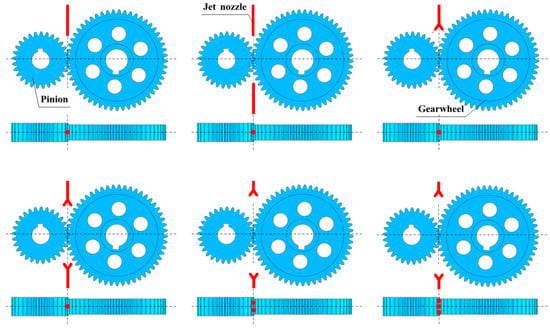
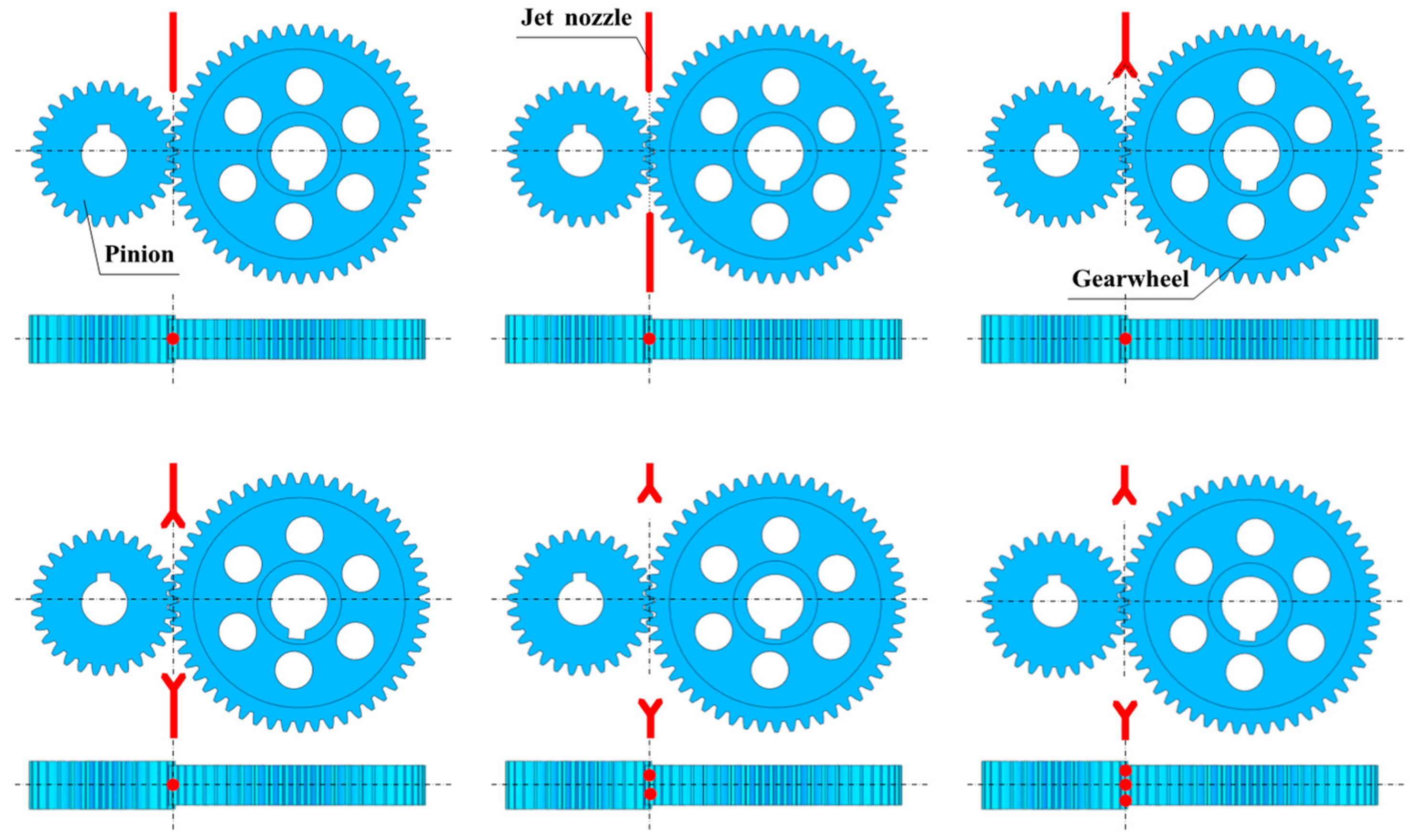
The design of the internal oil supply pipes in the gearbox is particularly crucial. The lubricating oil is sprayed onto the gear teeth through the pipe system to reduce the temperature of the tooth surface and minimize wear. To analyze the effect of different parameters of the spray pipes (position, angle, length, quantity, etc.) on the oil spraying lubrication effect on the tooth surface, the nozzle position of the meshing gears is shown in Figure 1. Moreover, the parameters of the nozzle inclination angle and length are provided in Table 2.
Figure 1.
The relative position of the meshing gears and the jet nozzle.
Table 2.
The geometric parameters of the nozzle.
3.2. Mesh Generation and Boundary Conditions
During the high-speed gear meshing process, the meshing teeth engage and disengage with each other, and the tooth side clearance constantly changes. Traditional slip mesh or moving mesh is prone to causing severe distortion or negative volume in the grids when dealing with such extremely small clearance movements, resulting in computational divergence.
The overlapping grid technique is adopted to solve this problem. Specifically, a rectangular static background mesh covering the entire calculation domain of the gearbox is constructed. Then, cylindrical sub-mesh regions wrapped around the tooth profiles of the driving and driven gears are established separately, and a high-density meshing area is created. The sub-mesh regions rotate around their respective axes at a specific speed along with the gears. There are overlapping areas between the sub-mesh regions and the component mesh. Data exchange of flow field variables is achieved by interpolating the mesh cells on the overlapping boundaries. To accurately capture the oil penetration in the meshing area and the evolution of the gas–liquid interface, local mesh densification was carried out in the meshing area of the background region and the tooth vicinity of the gear component area.
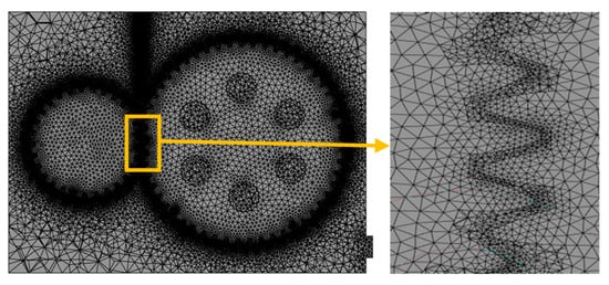
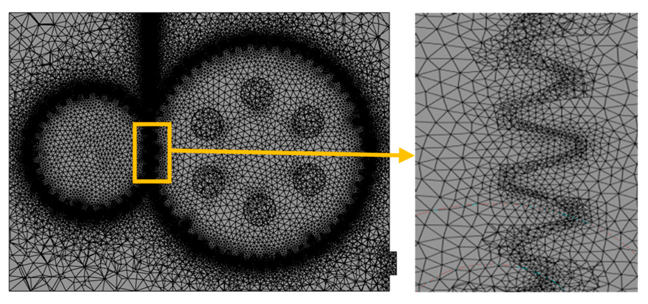
The moving mesh needs to achieve smooth updates during the calculation process. As shown in Figure 2, in order to strike a balance between calculation efficiency and accuracy, the mesh sizes for the end faces of the driving gear and driven gear, as well as the surface of the box, are set to 2 mm and 10 mm respectively. For the gear meshing area, two layers of meshing are added to avoid an excessive number of meshes resulting in a sharp increase. The resulting y+ values on the tooth surfaces ranged from 30 to 80, which falls within the logarithmic layer region and is appropriate for the wall-function approach employed by the k-ω SST turbulence model. This ensures reasonable resolution of the near-wall boundary layer without excessive computational cost.
Figure 2.
The mesh model of the gearbox.
The fuel injector is set as the pressure inlet, and the exhaust hole on the side of the gearbox is set as the pressure outlet. The surface of the gears and the inner wall of the gearbox are set as non-slip insulating walls. Considering the complete wetting property of the lubricating oil on the metal tooth surfaces, the static contact angle between the tooth surfaces and the oil is determined to be 20°. And the characteristic parameters of the oil and air are shown in Table 3. And the time step size was set to Δt = 1 × 10⁻⁶ s, ensuring that the maximum Courant number remained below 0.5 throughout the computational domain. Ten inner iterations were performed per time step to ensure convergence of the coupled pressure-velocity equations at each time step. The Geo-Reconstruct scheme was employed for VOF interface reconstruction, providing a sharp and accurate representation of the oil-air interface. The implicit body force formulation was activated to improve solution stability under high-speed rotating conditions. The present study adopts an isothermal assumption with a constant oil temperature of 40 °C. In actual high-speed gear operation, frictional heating can raise oil temperature significantly, reducing viscosity and affecting jet penetration, film thickness, and pressure development. Temperature-dependent viscosity would alter the Reynolds number and the balance between inertial and viscous forces, potentially shifting the optimal parameter ranges identified here. However, the isothermal assumption is commonly employed in parametric CFD studies of gear lubrication [7,8,11] as a first-order approximation, allowing systematic comparison of nozzle configurations without the added complexity of conjugate heat transfer.
Table 3.
Characteristic parameters of oil and air.
3.3. Verification of Mesh Independence
As the mesh size keeps decreasing and reaches a certain critical threshold, the model prediction results for key physical quantities will no longer undergo significant changes with the reduction in the mesh size. Moreover, as the mesh size decreases, the total number of mesh keeps increasing, resulting in a geometric growth in computational load. On the other hand, if the mesh size is too large, it will cause computational discretization and fail to accurately describe the detailed characteristics of the flow field. Therefore, this paper sets multiple mesh sizes for the tooth surface to verify the grid independence, in order to find the optimal tooth surface mesh size and balance the contradiction between computational accuracy and computational load.
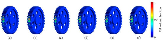
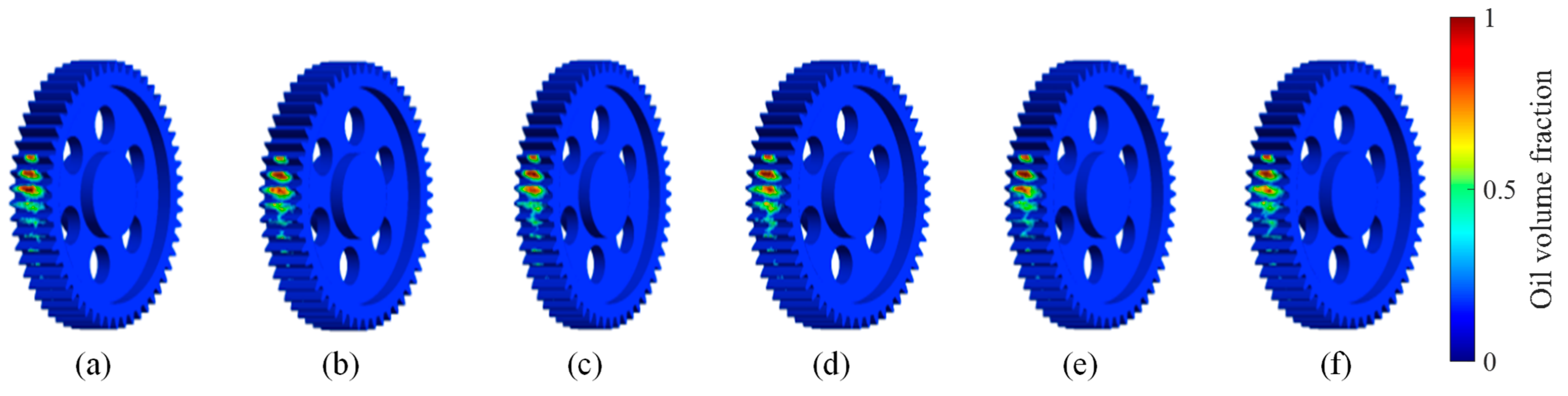
Based on the current situation of gear meshing and fuel injection trajectory, the meshing grids on the gear tooth surface were adjusted. The grid sizes for the tooth surface were set at 0.4 mm, 0.6 mm, 0.8 mm, 1.0 mm, 1.2 mm, and 1.4 mm, while the grid size for the gear end face was 2 mm and the grid size for the body was 10 mm. Here, the average volume fraction of the lubricating oil on the teeth of the driving gear is used as the criterion for determining the grid independence. When the relative error is less than 5%, it is determined that the grid can be regarded as meeting the grid accuracy requirements.
Based on the calculation results shown in Figure 3 and Table 4, it can be observed that as the mesh density of the tooth surface increases, the change in the oil volume fraction on the tooth surface becomes more gradual. The calculation results with the mesh size ranging from 0.4 mm to 0.6 mm are the smallest and are lower than the preset relative error of 5%. In addition, for the selected 0.6 mm mesh, the residuals for the continuity and momentum equations converged below 10−3, confirming numerical stability and integral-quantity convergence. This indicates that when the mesh reaches a certain density, the influence of discretization error on the results can be ignored, and the numerical solution becomes stable.
Figure 3.
The volume fraction of oil on the tooth surface under different mesh sizes: (a) 0.4 mm, (b) 0.6 mm, (c) 0.8 mm, (d) 1.0 mm, (e) 1.2 mm, (f) 1.4 mm.
Table 4.
The relative errors of the calculation results for different mesh sizes.
4. Results and Discussion
By changing parameters such as operating conditions and nozzle structure, the influence laws of each parameter on the internal process of the gearbox are analyzed and discussed. This provides reasonable design guidance for the lubrication design of high-speed gearboxes.
4.1. Transient Flow Field Analysis
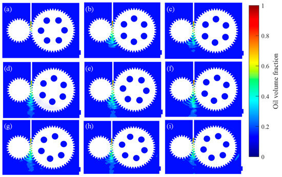
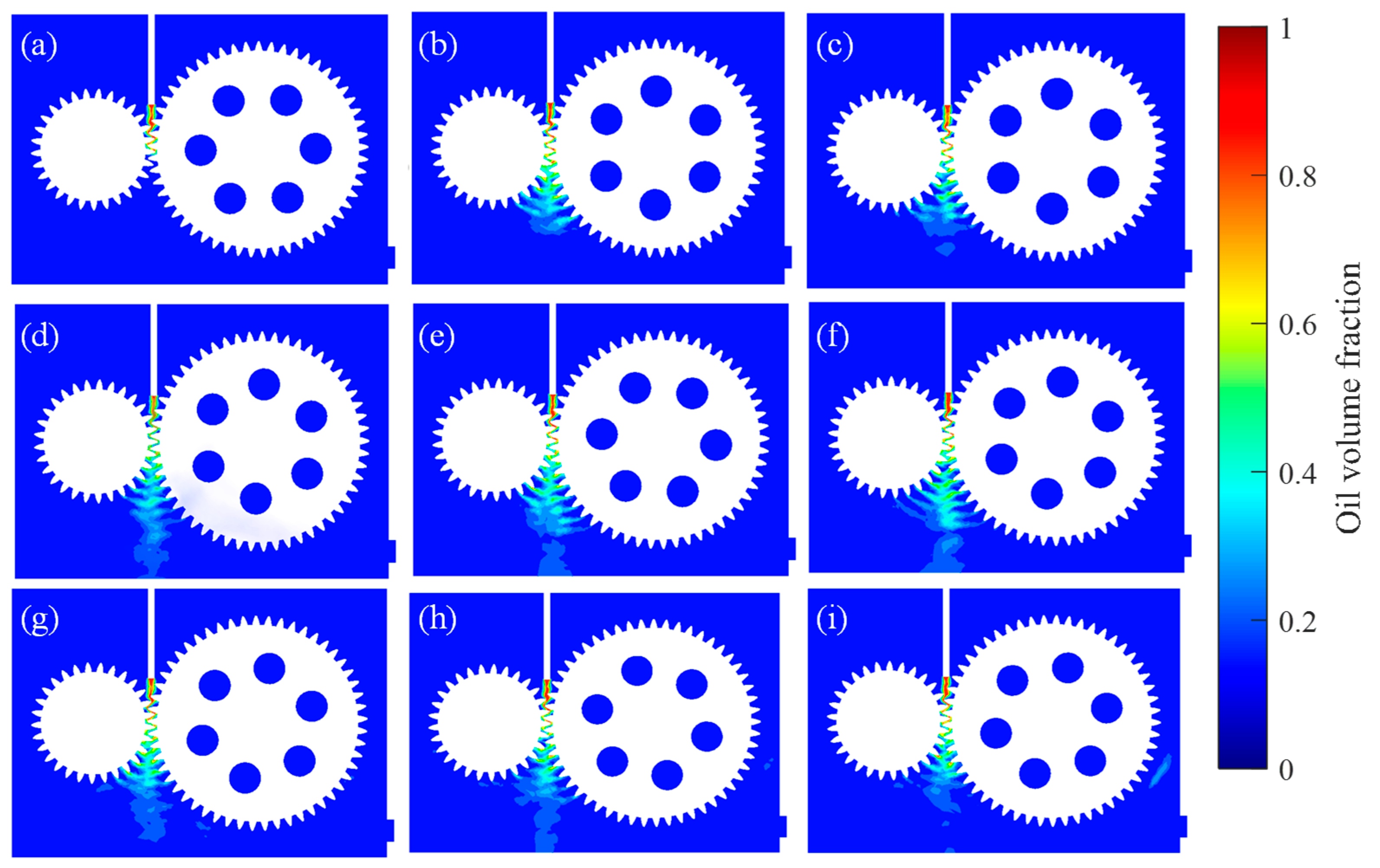
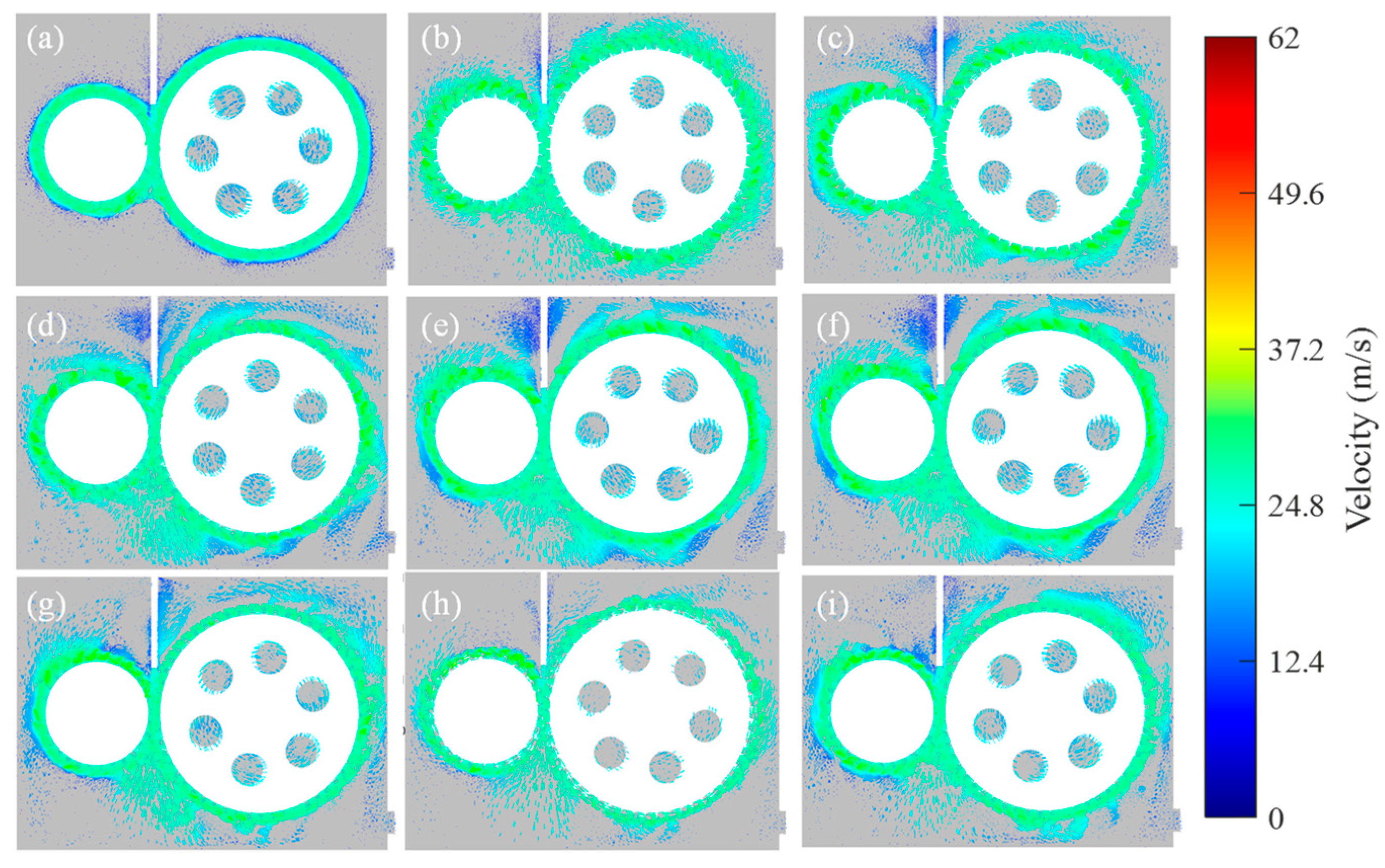
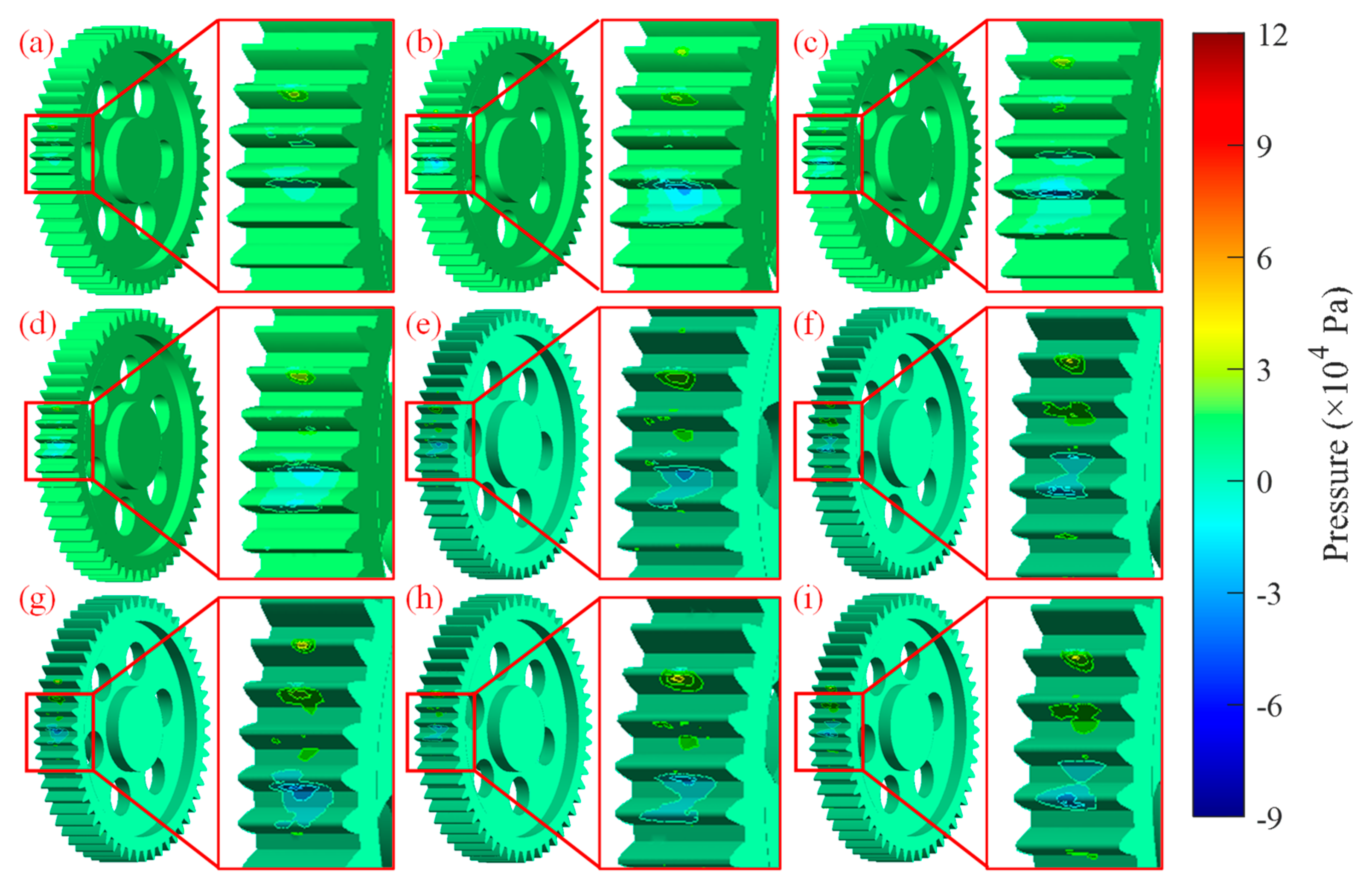
The oil, pressure and velocity distributions in the gearbox midsection flow field with the conditions of a single nozzle with driving wheel speed n = 9000 r/min and nozzle length of h = 40 mm, and an initial velocity v = 20 m/s of the nozzle opening are shown in Figure 4, Figure 5 and Figure 6 respectively.
Figure 4.
The oil volume fraction of the gearbox at different times: (a) 0.001 s, (b) 0.004 s, (c) 0.008 s, (d) 0.012 s, (e) 0.015 s, (f) 0.020 s, (g) 0.030 s, (h) 0.035 s, (i) 0.040 s.
Figure 5.
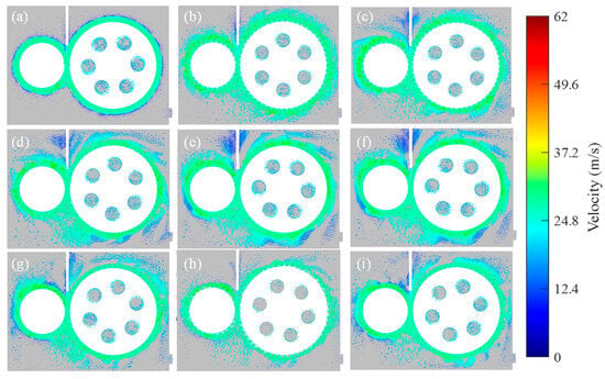
The flow velocity of the gearbox at different times: (a) 0.001 s, (b) 0.004 s, (c) 0.008 s, (d) 0.012 s, (e) 0.015 s, (f) 0.020 s, (g) 0.030 s, (h) 0.035 s, (i) 0.040 s.
Figure 6.
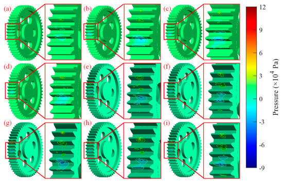
The tooth surface pressure at different times: (a) 0.001 s, (b) 0.004 s, (c) 0.008 s, (d) 0.012 s, (e) 0.015 s, (f) 0.020 s, (g) 0.030 s, (h) 0.035 s, (i) 0.040 s.
As can be seen from Figure 4, partial lubricating oil has begun to undergo atomization at 0.001 s; some lubricating oil has passed through the gear meshing area at 0.004 s, and the atomization phenomenon is more pronounced. During the period from 0.008 s to 0.012 s, both the driving and driven gears have completed one revolution. At this time, a certain amount of lubricating oil has entered the extraction, and the lubricating oil adhering to the surfaces of the two gears has significantly increased. When the time reaches 0.015 s, the lubricating oil has fallen into the lower side of the fluid domain, indicating that the lubricating oil has entered the lower gearbox housing, and the spray lubrication circuit has formed a closed loop. By 0.020 s, a large amount of lubricating oil has fallen into the lower gearbox housing. At 0.040 s, the driving gear has operated for about 6 revolutions, a large amount of lubricating oil has passed through the meshing area, and the lubricating oil has been fully dispersed throughout the fluid domain. Based on the above flow field distribution characteristics, it can be preliminarily judged that the time when the system reaches a steady state is approximately between 0.012 s and 0.02 s. Subsequent analysis needs to comprehensively evaluate by combining parameters such as the oil distribution on the tooth surface, flow field pressure distribution, and velocity distribution, in order to more accurately determine the steady-state conditions.
Figure 5 shows the distribution of velocity vectors within the flow field. It is obvious that the velocity vectors on the gear surface are significantly higher than those in other areas. Meanwhile, as the gears mesh, the velocity vector range in the meshing-out area remains stable. It occurs within 0.001 s to 0.004 s, and lubricating oil begins to enter the gear surface and the meshing area of the gears, and at 0.004 s, the vector direction is consistent with the rotation direction of the gears. During subsequent operation, the velocity vectors gradually disperse, indicating that the flow velocity gradually stabilizes and completely disperses in the fluid domain. However, there is no significant change in the velocity vector cloud chart after 0.012 s. Therefore, the fuel injection process can be divided into three stages: the first stage is from 0 s to 0.004 s, the initial movement stage; the second stage is from 0.004 s to 0.012 s, the transitional stage; and the third stage is the stable movement stage.
When the gears rotate at high speed, an airflow barrier is formed above the gear teeth tips. As the gears move, the lubricating oil gradually breaks through the airflow barrier and enters the meshing area. During this process, the lubricating oil and the airflow barrier conflict, resulting in a loss of the amount of lubricating oil entering the meshing area. This issue is one of the key points for subsequent optimization.
According to the distribution of lubricating oil pressure in Figure 6, the pressure of oil jet lubrication is mainly concentrated in the gear meshing area. At 0.001 s, the lubricating oil begins to enter the gear tooth surface, and at this time, the lubricating oil pressure is concentrated in the upper region of the gear. Between 0.004 s and 0.008 s, the lubricating oil flows through the gear meshing area, causing the pressure zones on both sides of the gear to become significantly larger. At 0.012 s, the lubricating oil is discharged and the variation in domain-averaged oil volume fraction or meshing-zone pressure is less than 5%, and from then on, the lubrication of the gear gradually tends to stabilize.
4.2. Rotational Speed
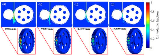
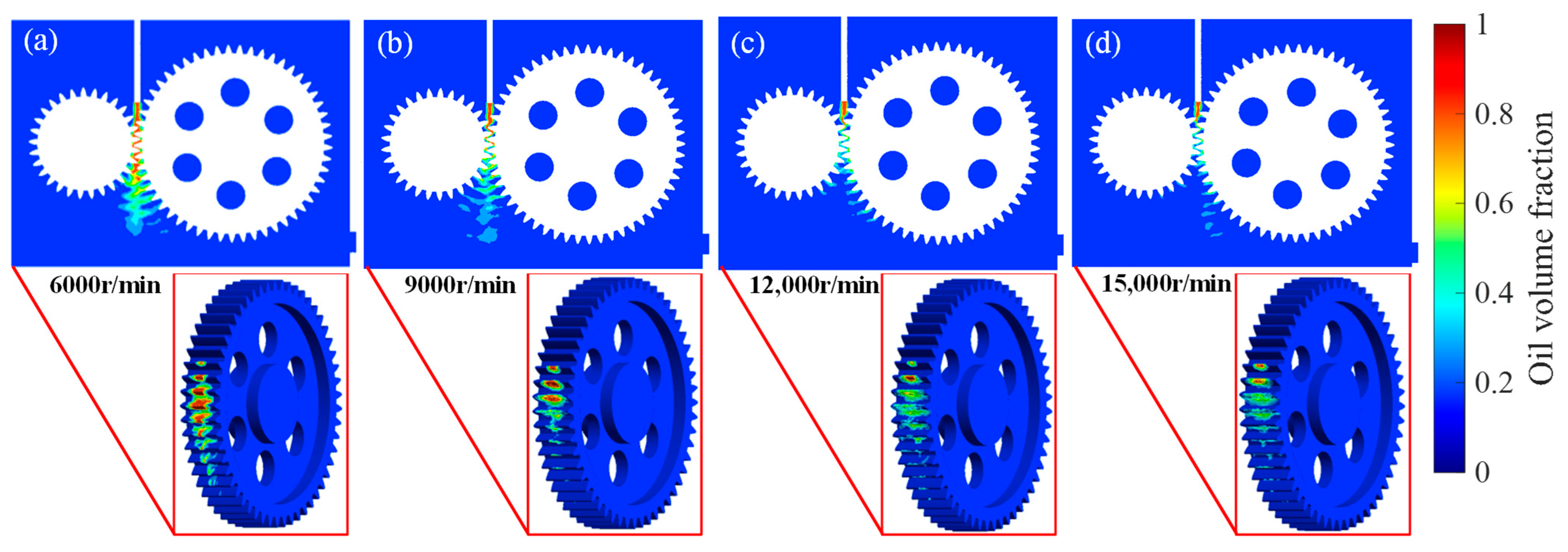
The gear rotational speed has a decisive influence on the carrying capacity of the lubricating oil, the thickness of the oil film, and the turbulent kinetic energy of the internal flow field. The distribution of oil volume fraction in the gear meshing area when the rotational speed is increased from 6000 r/min to 15,000 r/min is shown in Figure 7.
Figure 7.
The oil volume fraction at different rotational speeds: (a) 6000 r/min, (b) 9000 r/min, (c) 12,000 r/min, (d) 15,000 r/min.
As the gear rotational speed increases, there is a significant difference in the distribution of the oil. The accumulated oil volume in the upper part of the gear meshing area decreases. The lubricating oil is distributed relatively evenly as the gears rotate, and the atomization phenomenon of the lubricating oil is very obvious. At the same time, the oil fraction in the upper meshing area of the gears decreases with the increase in gear rotational speed, but the area of the gear oil fraction increases.
The slow rotational speed of the gears affects the velocity distribution of the flow field in the gearbox. As shown in Figure 8, the airflow velocity above the tooth tip gradually increases as the gear rotational speed increases, and the obstructive effect of the airflow barrier significantly increases. The resistance for the lubricating oil to break through the barrier and enter the meshing area also increases. When the gear rotational speed is 6000 r/min, the strength of the airflow barrier is weak, and the resistance for the lubricating oil to break through is small. However, the overall rotational speed of the gears is slow, resulting in a low efficiency of lubricating oil replenishment and renewal. As the gear rotational speed is increased to 15,000 r/min, the overly strong airflow barrier will block most of the lubricating oil outside the meshing area, and only a small amount of oil can enter, making it difficult to meet the lubrication requirements. Additionally, the strength of the airflow barrier is in the middle range at gear rotational speeds of 9000 r/min and 12,000 r/min. It can ensure that the lubricating oil has sufficient kinetic energy to break through the barrier and also does not cause a large loss of oil entering the meshing area due to excessive resistance. From the perspective of the flow field velocity distribution, the flow field movement state at a gear rotational speed of 9000 r/min is more suitable for the requirements of spray oil lubrication and is more conducive to maintaining a stable lubrication effect.
Figure 8.
The flow velocity at different rotational speeds: (a) 6000 r/min, (b) 9000 r/min, (c) 12,000 r/min, (d) 15,000 r/min.
4.3. Jet Velocity
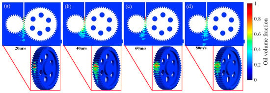
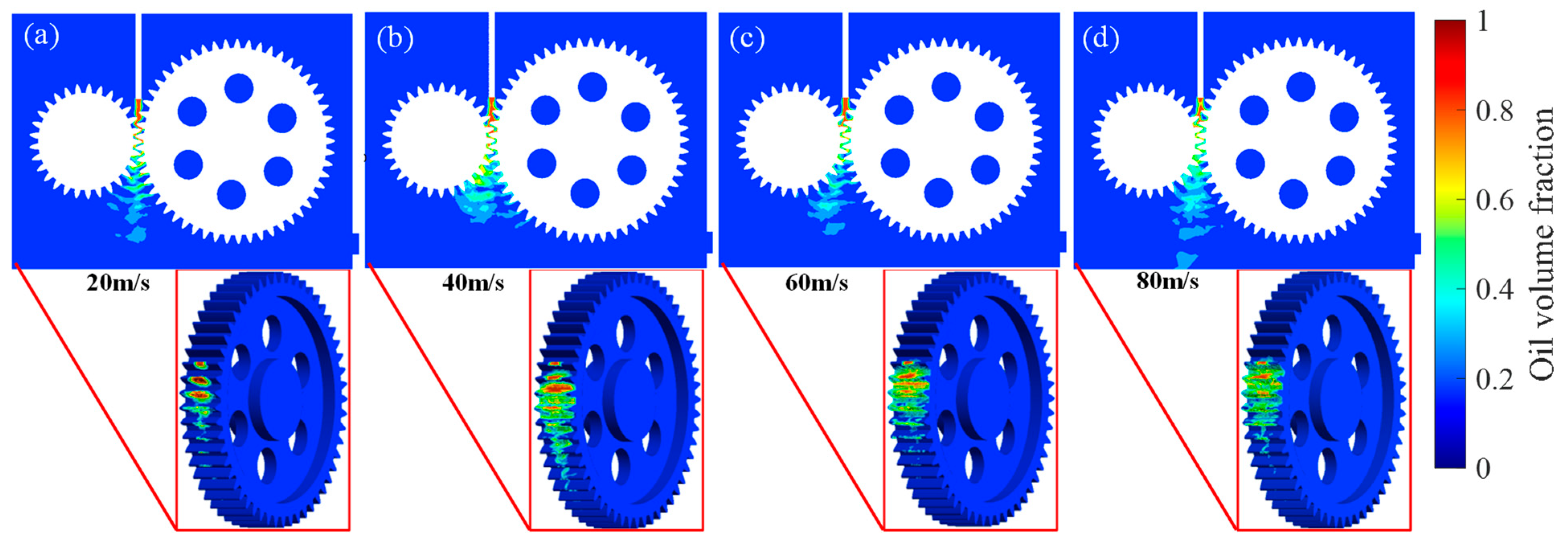
The influence of jet velocity on the oil distribution and flow dynamics within the gear system was investigated. Figure 9 and Figure 10 illustrate the spatial distribution of oil volume fraction and flow velocity under different jet velocities.
Figure 9.
The oil volume fraction at different jet velocities: (a) 20 m/s, (b) 40 m/s, (c) 60 m/s, (d) 80 m/s.
Figure 10.
The flow velocity at different jet velocities: (a) 20 m/s, (b) 40 m/s, (c) 60 m/s, (d) 80 m/s.
As shown in Figure 9, the oil volume fraction exhibits a highly localized and transient behavior near the meshing region of the driving and driven gears. At the spray velocity of 20 m/s, the oil mainly concentrates in the meshing area, forming a distinct and high-volume-fraction oil jet that penetrates deeply into the gear tooth gap. The oil is primarily concentrated in the intermeshing zone, forming a distinct, high-volume-fraction jet that penetrates into the gear tooth gap. The color bar indicates that the maximum oil volume fraction reaches approximately 0.8 to 1.0 in this region, suggesting efficient lubrication coverage at low speed. With increasing jet velocity, the oil jet becomes more dispersed and expansive, extending further along the gear flanks and tooth root regions. However, the peak volume fraction decreases slightly, indicating a trade-off between penetration depth and spray dispersion. At the velocity of 80 m/s, the oil distribution becomes more uniform along the gear periphery, but the intensity of the core jet weakens, potentially reducing targeted lubrication at the critical meshing point. The inset magnified gear view reveals that higher jet velocities lead to thinner, more fragmented oil films on the gear surfaces, which may compromise hydrodynamic lubrication performance despite broader coverage.
Figure 10 presents the velocity magnitude distribution induced by the jet impingement. At the flow velocity of 20 m/s, the flow velocity is highly concentrated near the nozzle exit and rapidly attenuates within the gear cavity. The maximum velocity is observed at the jet core, while the gear teeth experience relatively low velocities, indicating limited momentum transfer. As jet velocity increases to 40 m/s and 60 m/s, the high-velocity region expands radially outward, enhancing bulk fluid motion around the gears. Notably, at 60 m/s, a distinct high-velocity ring forms around the driven gear, suggesting the development of a toroidal vortex structure that may improve lubricant circulation.
The results indicate that jet velocity significantly affects both the spatial targeting and dynamic energy input of the lubrication system. Lower velocities (≤40 m/s) provide focused, high-concentration oil delivery to the meshing zone, which is beneficial for boundary and mixed lubrication regimes. In contrast, higher velocities (>60 m/s) enhance global fluid motion and cooling but risk film thinning and instability.
To quantitatively evaluate the trade-off, the penetration depth is defined as the maximum radial distance from the nozzle exit along the jet centerline where the oil volume fraction remains above 0.1. The spray dispersion is quantified by the standard deviation of the oil volume fraction distribution across the gear axial direction at a fixed radial position near the meshing zone. At 20 m/s, the penetration depth is approximately 15 mm, but the dispersion is low, resulting in highly localized oil delivery. At 80 m/s, the dispersion increases, but the penetration depth drops to about 8 mm due to enhanced atomization and windage. The optimal balance occurs at 40–60 m/s, where penetration depth and dispersion are both moderate. The underlying mechanism involves competition between inertial penetration and aerodynamic breakup. At low velocities, the oil jet’s inertia dominates, allowing deep penetration into the tooth gap, but the low momentum limits lateral spreading. As velocity increases, aerodynamic shear and drag from the high-speed rotating gears induce droplet breakup and atomization, widening the spray but reducing the coherent core’s ability to overcome the opposing airflow barrier. Hence, an intermediate velocity window exists where both penetration and coverage are adequate.
Optimal jet velocity selection should balance lubrication targeting efficiency with flow stability. For this gear configuration, the jet velocity of 40 m/s appears most promising, offering adequate penetration and sufficient circumferential coverage without inducing excessive turbulence.
4.4. Nozzle Placement
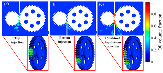
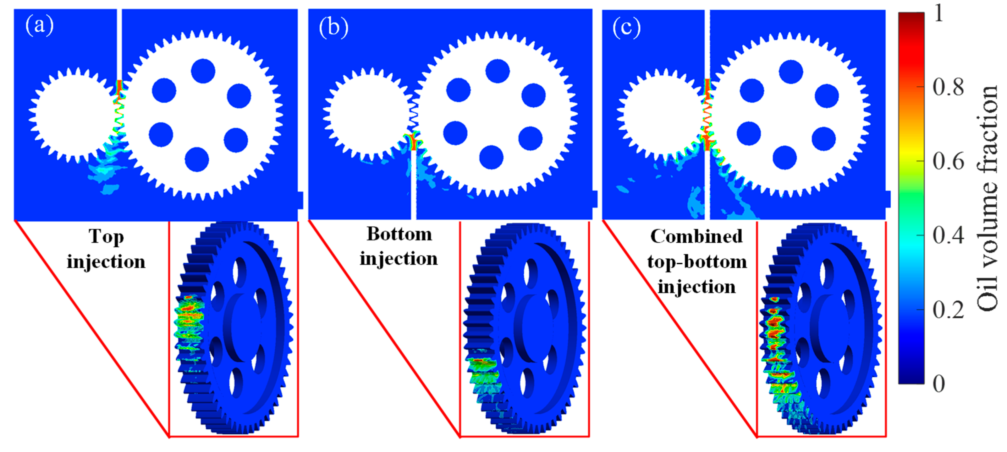
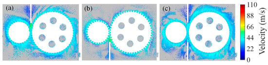
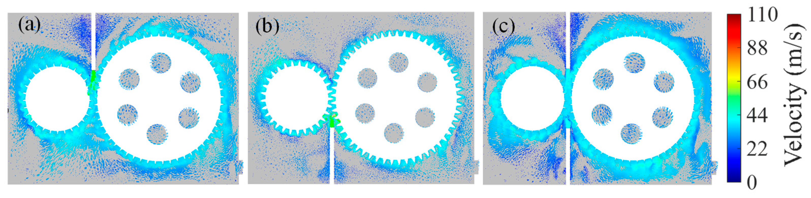
The effect of nozzle placement on oil distribution and internal flow dynamics was numerically investigated. Three configurations were considered: top injection, bottom injection and combined top–bottom injection. Corresponding contour plots of oil volume fraction and velocity magnitude are presented in Figure 11 and Figure 12, respectively.
Figure 11.
The oil volume fraction with different nozzle positions: (a) top injection, (b) bottom injection, (c) combined top–bottom injection.
Figure 12.
The flow velocity with different nozzle positions: (a) top injection, (b) bottom injection, (c) top and bottom injection.
Figure 11 depicts the spatial distribution of the oil volume fraction under the three nozzle arrangements. Under the top-injection condition, a concentrated oil jet with a local volume fraction approaching unity is observed at the upper meshing interface. The high-oil-concentration region is confined to the vicinity of the tooth engagement zone, whereas the lower gear flank exhibits negligible oil coverage, indicating inadequate lubrication of the lower load-bearing surfaces. For the bottom-injection configuration, the oil jet is directed toward the lower meshing region. A comparable high-volume-fraction core develops at the lower meshing interface, yet the oil distribution on the lower flank is marginally broader than that achieved by top injection on the upper flank. Nevertheless, the upper gear region remains poorly wetted. In contrast, the dual-nozzle arrangement yields a markedly more uniform oil distribution. Both the upper and lower meshing zones exhibit sustained high oil volume fractions, and the oil spreads continuously along the gear periphery. The magnified insets confirm that the dual-jet configuration effectively eliminates dry patches, providing full circumferential coverage of the meshing region.
The velocity magnitude contours in Figure 12 reveal the momentum transport characteristics associated with each nozzle position. In the top-injection case, the high-velocity core with velocity exceeding 70 m/s is localized near the nozzle exit and decays rapidly within the gear cavity. Velocities on the gear tooth surfaces remain below 20 m/s, implying limited convective mixing and poor lubricant recirculation. The bottom-injection scenario produces a qualitatively similar velocity field, albeit with the high-velocity region shifted downward. A weak upward flow is generated, moderately enhancing oil transport toward the upper gear region, but the overall flow vigor remains insufficient to achieve homogeneous mixing. Under the dual-nozzle configuration, two symmetric high-velocity jets interact to create a robust toroidal recirculation pattern within the gear chamber. Velocities in the inter-tooth space exceed 50 m/s over an extended area, and the average velocity magnitude throughout the domain is substantially higher than in either single-nozzle case. This intensified flow field promotes vigorous oil entrainment, improved heat transfer, and uniform lubricant distribution.
The numerical results demonstrate that nozzle position exerts a decisive influence on both the spatial targeting and the convective efficiency of the lubrication system. Quantitatively, the area of the gear flank with oil volume fraction below 0.05 is reduced from approximately 35% of the total flank area in the top-injection case to less than 5% in the dual-nozzle case. Regarding velocity magnitudes, the peak velocity in the single-nozzle cases reaches approximately 75 m/s near the nozzle exit but decays to below 20 m/s on the gear surfaces. In the dual-nozzle configuration, although the peak velocity is similar, the average velocity on the gear surfaces is approximately 35 m/s, nearly double that of the single-nozzle cases, indicating significantly improved convective mixing.
Single-nozzle configurations provide highly localized lubrication suitable for applications where only one side of the gear mesh experiences severe loading. However, they inherently suffer from asymmetric coverage, which may lead to uneven thermal and tribological conditions. The dual-nozzle strategy overcomes these limitations by delivering lubricant symmetrically to both sides of the meshing interface. The resulting flow field not only ensures complete wetting of the gear flanks but also establishes a strong recirculation loop that enhances oil replenishment and cooling. From an engineering perspective, the dual-nozzle arrangement is recommended for high-speed or heavy-duty gear systems where uniform lubrication and effective heat dissipation are critical.
4.5. Nozzle Included Angle and Length
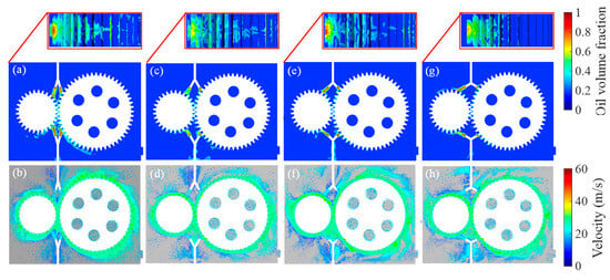
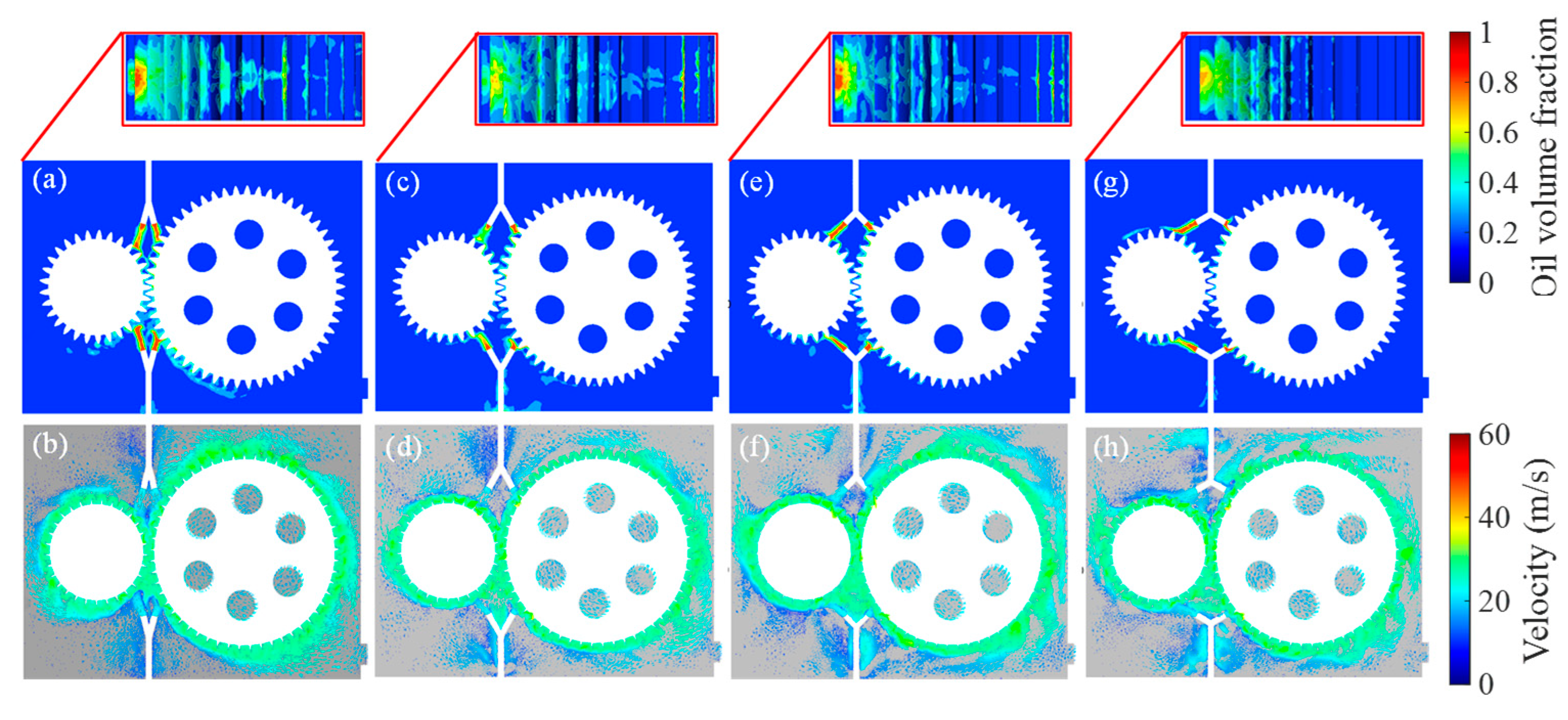
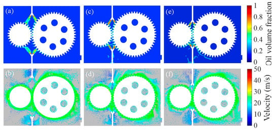
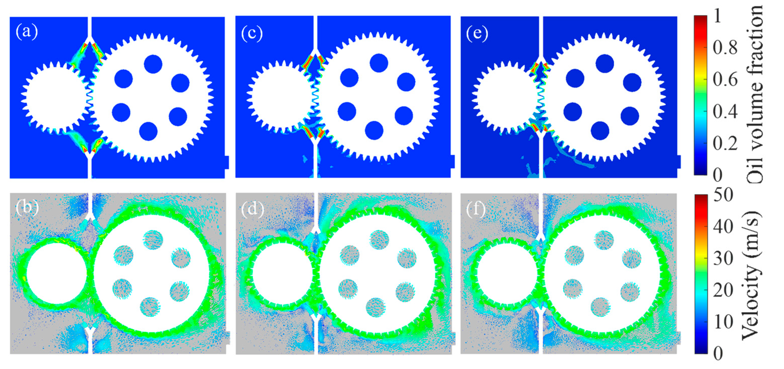
The nozzle inclination angle determines the direction of the jet spread, and the nozzle length controls the penetration distance of the jet, which has significant effects on the oil lubrication and flow dynamics. Figure 13 and Figure 14 illustrate the oil volume fraction and flow velocity distributions under varying included angles (30°, 60°, 90°, 120°) and nozzle lengths (20 mm, 30 mm, 35 mm), respectively.
Figure 13.
The oil volume fraction and flow velocity with different nozzle included angles: (a,b) 30°, (c,d) 60°, (e,f) 90°, and (g,h) 120°.
Figure 14.
The oil volume fraction and flow velocity with different nozzle lengths: (a,b) 20 mm, (c,d) 30 mm, and (e,f) 35 mm.
At the included angle of 30°, the oil jet is highly collimated, forming a narrow, high-intensity jet that penetrates deeply into the gear meshing zone. The maximum oil volume fraction is localized at the tooth engagement region, with minimal dispersion along the gear flanks. While this ensures precise lubrication of the critical meshing interface, the limited spread reduces coverage of the gear periphery. As the included angle increases to 60°and 90°, the jet expands radially, and the oil volume fraction distribution becomes more uniform along the gear flanks. The high-volume fraction core persists at the meshing zone, but the lateral spread of oil extends further along the gear teeth, enhancing the lubricant retention on the non-meshing surfaces. For the largest angle of 120°, the jet diverges excessively, leading to a significant reduction in the peak oil volume fraction at the meshing zone. Although the oil spreads widely along the gear circumference, the weakened jet momentum compromises the lubricant’s ability to penetrate the tooth gap, potentially causing insufficient lubrication at the critical contact points.
The velocity magnitude reveals a strong correlation with the included angle. At the included angle of 30°, the high-velocity core is confined to a narrow region near the nozzle, with rapid velocity decay in the gear cavity. Gear tooth surfaces experience low velocities, limiting convective mixing. For the included angle of 60° and 90°, the high-velocity region expands, and a distinct toroidal vortex forms around the driven gear. This vortex enhances bulk fluid motion, with velocities in the inter-tooth space exceeding 40 m/s. The improved flow vigor promotes better oil entrainment and heat dissipation. At the included angle of 120°, the flow field becomes highly turbulent due to excessive jet divergence. While velocities remain high in the near-nozzle region, the lack of a coherent vortex structure leads to chaotic mixing, which may lead to reduced lubrication efficiency and potential surface damage under prolonged operation.
Figure 14 illustrates the oil volume fraction and flow velocity for three nozzle lengths. With a 20 mm nozzle, the short nozzle length restricts jet development, resulting in a compact, high-velocity jet that delivers oil directly to the meshing zone. The coverage along the gear flanks is limited, and the oil film on the gear surfaces is relatively thin. For the 30 mm nozzle, the jet has sufficient length to fully develop before impinging on the gears. This creates a more uniform oil distribution, and the oil spreads evenly along the gear peripheries. At a nozzle length of 35 mm, the nozzle length exceeds the optimal development distance, causing the jet to disperse prematurely. The peak oil volume fraction at the meshing zone decreases, and the oil distribution becomes less uniform, with localized dry spots appearing on the gear flanks. To quantify the coverage, the percentage of the gear flank area with oil volume fraction above 0.1 was calculated. For the 30 mm nozzle, this coverage reached 82%, compared to 65% for the 20 mm nozzle and 70% for the 35 mm nozzle, confirming the 30 mm length as optimal.
For the 20 mm nozzle, the high-velocity core is narrow and concentrated, with limited velocity penetration into the gear cavity. Gear tooth velocities remain at around 20 m/s, hindering lubricant circulation. The 30 mm nozzle produces a well-developed jet that generates a robust toroidal vortex around the gears. Velocities in the inter-tooth space exceed 40 m/s, facilitating efficient oil mixing and heat transfer. For the 35 mm nozzle, the over-long nozzle causes the jet to diverge before reaching the gears, resulting in a broader but weaker high-velocity region. Although the average velocity in the cavity is higher, the lack of a focused momentum transfer reduces the effectiveness of oil delivery to the meshing zone.
This indicates that an excessively small nozzle inclination angle will result in excessive concentration, while an angle greater than 90° will cause excessive dispersion, thereby reducing the penetration power. A length of 30 mm (for the studied gear geometry) optimizes jet development, enabling uniform oil distribution and robust flow circulation. Shorter nozzles restrict jet expansion, while longer nozzles cause premature dispersion.
4.6. Number of Nozzles
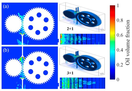
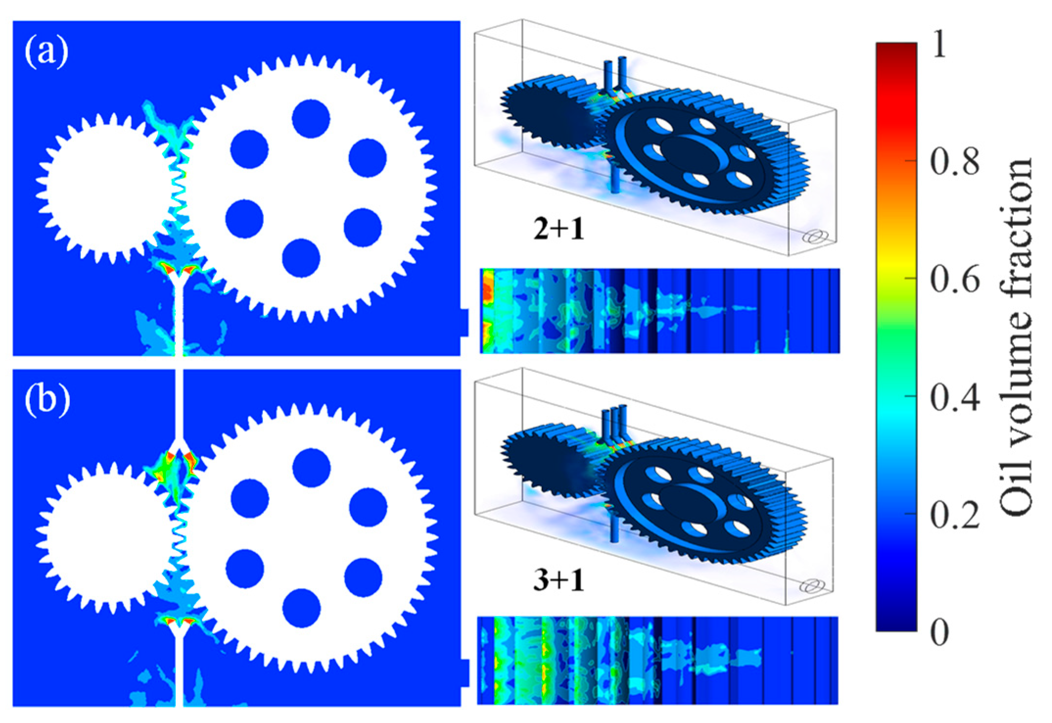
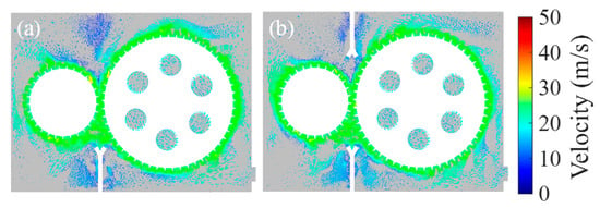
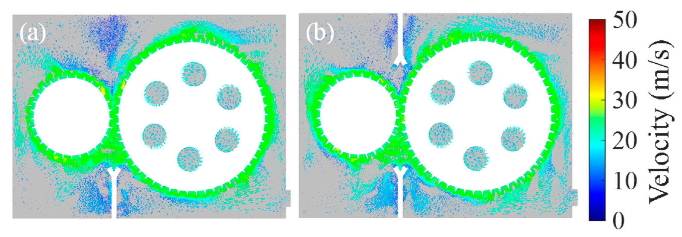
The effect of nozzle quantity and layout on oil distribution and flow dynamics was investigated by comparing the 2 + 1 layout (two nozzles at the upper meshing zone inlet, and one nozzle at the exit of the lower meshing zone). and the 3 + 1 layout (three nozzles at the upper meshing zone inlet, and one nozzle at the exit of the lower meshing zone). Contours of oil volume fraction and velocity magnitude are presented in Figure 15 and Figure 16, respectively.
Figure 15.
The oil volume fraction with different nozzle numbers: (a) 2 + 1 layout, and (b) 3 + 1 layout.
Figure 16.
The flow velocity with different nozzle numbers: (a) 2 + 1 layout, and (b) 3 + 1 layout.
Two nozzles on the driven gear generate two discrete oil jets, creating a split lubrication pattern. High oil volume fractions are confined to the vicinities of the two jets, with limited lateral spread along the gear flanks. The meshing zone between the driven and idler gears receives partial coverage, while the upper flank of the driven gear exhibits low oil volume fractions, indicating insufficient lubrication for this region. The magnified insets confirm the localized nature of the oil distribution, with distinct high-concentration patches separated by low-volume-fraction gaps. Adding a third nozzle on the driven gear significantly improves spatial uniformity. The oil jets merge more effectively, forming a nearly continuous high-volume-fraction region along the entire meshing interface of the driven gear. The upper flank, previously poorly wetted, now exhibits sustained oil coverage, eliminating the dry patch observed in the 2 + 1 layout.
Figure 16 reveals the velocity magnitude distribution induced by the two nozzle layouts, highlighting differences in momentum transfer and flow structure. Two high-velocity jets are observed, corresponding to the two nozzles. These jets create localized flow agitation but fail to establish a coherent circulatory pattern within the gear cavity. Velocities on the gear tooth surfaces remain low, and the flow between the driven and idler gears is dominated by two isolated, high-velocity channels with limited cross-flow. This restricts the overall lubricant circulation efficiency, as the flow lacks the energy to disperse oil evenly.
The three-jet configuration generates a more complex and vigorous flow field. A continuous high-velocity ring forms around the driven gear, driven by the combined momentum of the three jets. This ring-like structure promotes toroidal recirculation within the gear cavity, enhancing bulk fluid motion and oil mixing. The third jet disrupts the symmetry of the 2 + 1 flow, inducing a weak axial flow component that further improves oil transport toward the upper flank of the driven gear.
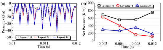
Figure 17 illustrates the time-resolved pressure characteristics within the gear meshing zone under different nozzle configurations. As depicted in Figure 17a, the instantaneous engagement pressure exhibits periodic fluctuations corresponding to the meshing cycle of the gears, characterized by sharp negative spikes indicative of impact and squeezing effects. Compared to the baseline 1 + 1 layout, the 2 + 1 and 3 + 1 configurations demonstrate a notable reduction in the magnitude of these negative pressure peaks, suggesting that multi-point injection mitigates the impact during gear engagement. Furthermore, Figure 17b presents the evolution of the integrated net pressure, revealing a distinct trend: the 1 + 1 layout maintains the highest initial net pressure but exhibits a significant decline over time, likely due to lubricant film breakdown or starvation. Conversely, the 2 + 1 layout shows a continuous and substantial decay from 600 kPa to 100 kPa, indicating an unstable lubrication state. In contrast, the 3 + 1 layout stabilizes at an intermediate pressure level, highlighting its superior capability to sustain consistent hydrodynamic pressure and ensure continuous oil film replenishment throughout the operating cycle. In the 2 + 1 layout, the two discrete oil jets leave uncovered gaps along the gear face width. When a tooth pair enters the meshing zone in these gaps, the local oil supply is insufficient, leading to rapid cavity formation and a sharp negative pressure spike. In contrast, the third nozzle in the 3 + 1 layout fills the gap, creating a continuous oil curtain that ensures the meshing zone is flooded with lubricant throughout the engagement cycle. This prevents vapor cavity formation and cushions the impact, thereby reducing the magnitude of negative pressure peaks (Figure 17a) and maintaining a more stable net pressure over time (Figure 17b). The continuous oil film also promotes faster replenishment, sustaining hydrodynamic lubrication.
Figure 17.
The pressure with different nozzle numbers: (a) engagement pressure, and (b) net pressure.
The number of nozzles directly affects the spatial coverage and flow vigor of the lubrication system. The 2 + 1 nozzle layout can provide targeted lubrication for the meshing zone but suffers from incomplete coverage and limited flow circulation. Suitable for applications where lubrication demand is concentrated in a specific region. And the 3 + 1 nozzle layout achieves near-uniform oil distribution along the gear flanks and meshing interface, while establishing a robust recirculation pattern that enhances mixing and cooling. The improved flow vigor and coverage make it preferable for high-speed, heavy-load, or thermally demanding gear systems. Although the 3 + 1 layout requires a higher oil supply flow rate than the 2 + 1 layout, which increases pumping power consumption, the net energy impact must be evaluated holistically. Improved lubrication reduces frictional losses at the gear mesh and enhances heat dissipation, lowering operating temperatures and extending component life.
The oil volume fraction, film continuity and pressure stability are directly relevant to the lubricant entrainment process that governs film formation at the gear mesh. In high-speed spur gears, the oil jet must deliver sufficient lubricant to the inlet region of the meshing zone before tooth contact occurs. A higher oil volume fraction in this region (as achieved by the dual-nozzle and 3 + 1 layouts) ensures adequate lubricant supply for entrainment into the converging wedge, promoting full-film hydrodynamic or mixed lubrication conditions. Conversely, low oil coverage leads to lubricant starvation, where the film thickness is governed solely by the residual oil on tooth surfaces from previous engagements, increasing the risk of boundary lubrication and scuffing. The suppression of negative-pressure fluctuations by the 3 + 1 layout also contributes to film stability, as pressure dips can cause cavitation-induced film collapse. These observations are consistent with classical EHL theory, where film thickness depends on entrainment velocity, lubricant viscosity, and the availability of oil at the contact inlet.
5. Conclusions
Based on the CFD numerical simulation method, this study systematically investigated the influence of nozzle parameters (including jet velocity, nozzle position, nozzle included angle, nozzle length, and the number of nozzles) on the lubrication performance of high-speed spur gear pairs. The transient evolution of the flow field and the steady-state characteristics were analyzed. The main conclusions are as follows:
- (1)
- The transient flow field evolves through three stages: initial movement (0–0.004 s), transition (0.004–0.012 s), and stable movement (after 0.012 s). A gear rotational speed of 9000 r/min optimally balances airflow barrier breakthrough and oil retention.
- (2)
- Jet velocity significantly affects the spatial targeting and dynamic energy input of the lubrication system. A jet velocity of 40–60 m/s achieves an optimal balance between penetration depth and spray dispersion. Lower velocities limit coverage, while higher velocities cause film thinning and instability.
- (3)
- A dual-nozzle configuration eliminates dry patches and establishes a stable recirculation structure, outperforming single-nozzle setups in spatial uniformity.
- (4)
- A nozzle inclination angle of 60–90° with a length of 30 mm provides the best combination of target oil delivery and coverage. Smaller angles concentrate the jet excessively, while larger angles cause premature dispersion.
- (5)
- The 3 + 1 nozzle layout enhances oil film continuity and suppresses abrupt negative-pressure fluctuations, stabilizing the hydrodynamic lubrication effect. This layout is recommended for high-speed, heavy-duty applications despite higher pumping demand, as the net energy saving from reduced friction is expected to be positive.
In summary, this research provides quantitative design guidance for optimizing the nozzle geometry and layout of high-speed gearbox lubrication systems. The application of these optimized parameters helps to improve reliability and is expected to reduce energy loss through lowered frictional losses, though the net energy benefit requires further quantification in future work.
It should be noted that the present study is purely numerical and lacks direct experimental validation. Future work should conduct specific experiments, such as high-speed imaging of the jet penetration process and measurement of the oil film thickness on the tooth surface, in order to quantitatively confirm the predicted optimal parameter ranges. In addition, the present framework should be expanded to capture the full complexity of high-speed gear lubrication. Firstly, coupled thermo-fluidic simulations incorporating conjugate heat transfer and temperature-dependent viscosity are needed to evaluate the thermal performance of the recommended nozzle configurations and to identify potential trade-offs between coverage and cooling. Second, fluid–structure interaction (FSI) modeling could capture the influence of oil pressure and momentum on gear tooth deformation and vibration, which in turn affect film thickness and contact conditions. Third, integrating the present lubrication model with multi-body gear dynamics would allow investigation of how profile modifications, undercuts, and dynamic tooth loading affect oil film replenishment and thermal dissipation under transient operating conditions. Such a coupled framework would provide a comprehensive tool for the design of high-speed, high-power-density gearbox lubrication systems.
Author Contributions
Conceptualization, L.X. and X.D.; methodology, X.D.; software, X.D.; validation, L.X. and H.Z.; formal analysis, L.X., N.Z. and L.Z.; investigation, X.D., K.Z. and H.Z.; resources, L.X., X.D. and K.Z.; data curation, L.X.; writing—original draft preparation, L.X. and X.D.; writing—review and editing, L.X., X.D. and M.Z.; visualization, L.X. and X.D.; supervision, L.X.; project administration, L.X.; funding acquisition, L.X. All authors have read and agreed to the published version of the manuscript.
Funding
This research was funded by the National Natural Science Foundation of China (52405068) and the Young Talent Fund of Xi’an Association for Science and Technology (0959202613050).
Data Availability Statement
The original contributions presented in this study are included in the article. Further inquiries can be directed to the corresponding author.
Conflicts of Interest
Naifeng Zhang, Long Zhang, Kunzhi Zhang and Hantai Zhang are emplyed by Liaocheng Xintai Machine Tool Co., Ltd., Liaocheng 252200, China. The authors declare no conflicts of interest.
References
- Liu, H.; Liu, H.J.; Zhu, C.C.; Parker, R.G. Effects of lubrication on gear performance: A review. Mech. Mach. Theory 2020, 145, 103701. [Google Scholar] [CrossRef] [Scilit]
- Höhn, B.R.; Michaelis, K.; Otto, H.P. Minimised gear lubrication by a minimum oil/air flow rate. Wear 2009, 266, 461–467. [Google Scholar] [CrossRef] [Scilit]
- Dai, Y.; Wu, W.; Zhou, H.B.; Zhang, J.; Ma, F.Y. Numerical simulation and optimization of oil jet lubrication for rotorcraft meshing gears. Int. J. Simul. Model. 2018, 17, 318–326. [Google Scholar] [CrossRef] [Scilit]
- Mo, S.; Zhou, C.P.; Dang, H.Y. Lubrication Effect of the Nozzle Layout for Arc Tooth Cylindrical Gears. J. Tribol.-Trans. Asme 2022, 144, 031202. [Google Scholar] [CrossRef] [Scilit]
- Andersson, M.; Sosa, M.; Olofsson, U. Efficiency and temperature of spur gears using spray lubrication compared to dip lubrication. Proc. Inst. Mech. Eng. Part J-J. Eng. Tribol. 2017, 231, 1390–1396. [Google Scholar] [CrossRef] [Scilit]
- Liu, H.; Jurkschat, T.; Lohner, T.; Stahl, K. Determination of oil distribution and churning power loss of gearboxes by finite volume CFD method. Tribol. Int. 2017, 109, 346–354. [Google Scholar] [CrossRef] [Scilit]
- Wang, Y.Z.; Niu, W.T.; Wei, S.; Song, G.H. Influence of spin flow on lubricating oil jet-Design method of oil spray parameters to high speed spur gears. Tribol. Int. 2015, 92, 290–300. [Google Scholar] [CrossRef] [Scilit]
- Niu, W.T.; Wang, Y.Z.; Chen, Y.Y.; Song, G.H. Air barrier effect in out of mesh jet lubrication of ultra-high speed spur gears. Ind. Lubr. Tribol. 2017, 69, 81–87. [Google Scholar] [CrossRef] [Scilit]
- Wang, Y.Z.; Song, G.H.; Niu, W.T.; Chen, Y.Y. Optimized design of spray parameters of oil jet lubricated spur gears. Tribol. Int. 2018, 120, 149–158. [Google Scholar] [CrossRef] [Scilit]
- Zhong, J.F.; Dai, Y.; Liang, C.Y.; Zhu, X.; Xu, L.J. CFD investigation of air-oil two-phase flow in oil jet nozzle. Proc. Inst. Mech. Eng. Part C-J. Mech. Eng. Sci. 2022, 236, 10079–10089. [Google Scholar] [CrossRef] [Scilit]
- Keller, M.C.; Kromer, C.; Cordes, L.; Schwitzke, C.; Bauer, H.J. CFD study of oil-jet gear interaction flow phenomena in spur gears. Aeronaut. J. 2020, 124, 1301–1317. [Google Scholar] [CrossRef] [Scilit]
- Hu, X.Z.; Li, P.F.; Quan, C.; Wang, J.N. CFD Investigation on Oil Injection Lubrication of Meshing Spur Gears via Lattice Boltzmann Method. Lubricants 2022, 10, 184. [Google Scholar] [CrossRef] [Scilit]
- Tang, P.X.; Li, Z.M.Q.; Hou, X.Y.; Li, L.T.; Xi, R.S.; Chen, Y.Y. Influence of Oil Injection Lubrication Parameters of High-Speed Internal Meshing Gear Based on the Computational Fluid Dynamics. Lubricants 2024, 12, 390. [Google Scholar] [CrossRef] [Scilit]
- Gu, Y.H.; Zhang, X.X.; Li, L.; Yan, Q. Investigation into the Dynamic Evolution Characteristics of Gear Injection Lubrication Based on the CFD-VOF Model. Processes 2025, 13, 2540. [Google Scholar] [CrossRef] [Scilit]
- Gong, R.; Liu, C.G.; Che, H.J.; Li, G. Numerical Investigation on Lubrication Performance of Rotating Oil Circuit in Planetary Gear Reducer. Tribol. Trans. 2026, 69, 310–323. [Google Scholar] [CrossRef] [Scilit]
- Qiao, Z.Z.; Zhou, C.J.; Su, J.; Jiang, X.H. A novel dynamic heat-flow coupled model under spray lubrication for high-speed gears: CFD simulation and experimental validation. Simul. Model. Pract. Theory 2024, 131, 102867. [Google Scholar] [CrossRef] [Scilit]
- Zhang, Z.Q.; Li, J.Y.; Zou, T.A.; Hou, W.; An, Y.Y.; Liu, J.H. Optimisation of Key Parameters of Oil Injection Lubrication and Analysis of Lubrication Efficiency of Textured Gears. Lubr. Sci. 2026, 38, 130–150. [Google Scholar] [CrossRef] [Scilit]
- Zou, T.G.; Yan, Q.D.; Hou, W.; Wang, C.Y.; Zhang, Z.Q.; Li, J.Y. Numerical Simulation and Experimental Study on the Role of Jet Angle in Controlling the Flow of Transmission Gears. Lubricants 2025, 13, 225. [Google Scholar] [CrossRef] [Scilit]
- Zhang, H.C.; Liu, Y.P.; Chen, Q. Analysis and Research on Oil Injection Lubrication of Variable Tooth Thickness Gear Based on CFD Method. Appl. Sci. 2025, 15, 297. [Google Scholar] [CrossRef] [Scilit]
- Yang, D.; Liu, H.; Zhong, J.F.; Zhu, X.; Dai, Y. Influence of Nozzle Layouts on the Heat-Flow Coupled Characteristics for Oil-Jet Lubricated Spur Gears. Lubricants 2023, 11, 25. [Google Scholar] [CrossRef] [Scilit]
- Li, L.L.; Ye, Y.J.; Zhang, Y.Z.; Zhao, K. Calculation method of impingement depth and multiple objective optimizations of nozzle layout for aviation gears considering windage. Sci. Rep. 2025, 15, 17122. [Google Scholar] [CrossRef] [Scilit] [PubMed]
- Zhu, X.; Dai, Y.; Ma, F.; Ouyang, B. Mathematical modeling and numerical simulation for determining an optimized oil jet layout for spiral bevel gear lubrication. Proc. Inst. Mech. Eng. Part J-J. Eng. Tribol. 2021, 235, 611–628. [Google Scholar] [CrossRef] [Scilit]
- Torres, T.; Changenet, C.; Touret, T.; Guilbert, B. A new formulation for convective heat transfer in oil jet lubricated spur gears. Proc. Inst. Mech. Eng. Part J-J. Eng. Tribol. 2025, 239, 1232–1245. [Google Scholar] [CrossRef] [Scilit]
- Torres, T.; Changenet, C.; Touret, T.; Guilbert, B. A New Experimental Methodology to Study Convective Heat Transfer in Oil Jet Lubricated Gear Units. Lubricants 2023, 11, 408. [Google Scholar] [CrossRef] [Scilit]
- Liu, J.; Ni, H.T.; Xu, Z.D.; Pan, G. A simulation analysis for lubricating characteristics of an oil-jet lubricated ball bearing. Simul. Model. Pract. Theory 2021, 113, 102371. [Google Scholar] [CrossRef] [Scilit]
- Dai, Y.; Jia, J.F.; Ouyang, B.; Bian, J.N. Determination of an Optimal Oil Jet Nozzle Layout for Helical Gear Lubrication: Mathematical Modeling, Numerical Simulation, and Experimental Validation. Complexity 2020, 2020, 2187027. [Google Scholar] [CrossRef] [Scilit]
- Hu, H.H. Fluid Mechanics, 5th ed.; Academic Press: Boston, MA, USA, 2012; pp. 421–472. [Google Scholar]
- Xie, C.; Yu, W. Gear dynamic modelling based on the concept of dynamic mesh stiffness: Theoretical study and experimental verification. J. Mech. Sci. Technol. 2022, 36, 4953–4965. [Google Scholar] [CrossRef] [Scilit]
- Peng, Q.L.; Gui, L.J.; Fan, Z.J. Numerical and experimental investigation of splashing oil flow in a hypoid gearbox. Eng. Appl. Comput. Fluid Mech. 2018, 12, 324–333. [Google Scholar] [CrossRef] [Scilit]
- Fondelli, T.; Andreini, A.; Da Soghe, R.; Facchini, B.; Cipolla, L. Numerical Simulation of Oil Jet Lubrication for High Speed Gears. Int. J. Aerosp. Eng. 2015, 2015, 752457. [Google Scholar] [CrossRef] [Scilit]
- Lin, L.Y.; Wang, C.; Chen, B.Z.; Wang, X.; Zhou, Q.S.; Kong, X.Y.; Feng, G. Aerodynamic characteristics analysis of civil airliner nose and main landing gear systems. Mech. Based Des. Struct. Mach. 2026, 54, 2662505. [Google Scholar] [CrossRef] [Scilit]
- Ageze, M.B.; Hu, Y.F.; Wu, H.C. Comparative Study on Uni- and Bi-Directional Fluid Structure Coupling of Wind Turbine Blades. Energies 2017, 10, 1499. [Google Scholar] [CrossRef] [Scilit]





Disclaimer/Publisher’s Note: The statements, opinions and data contained in all publications are solely those of the individual author(s) and contributor(s) and not of MDPI and/or the editor(s). MDPI and/or the editor(s) disclaim responsibility for any injury to people or property resulting from any ideas, methods, instructions or products referred to in the content. |
© 2026 by the authors. Licensee MDPI, Basel, Switzerland. This article is an open access article distributed under the terms and conditions of the Creative Commons Attribution (CC BY) license.