


Abstract
Acoustic emission (AE) monitoring has been widely employed for condition assessment of mechanical seals. However, the physical origin of high-frequency AE activity under elastohydrodynamic lubrication (EHL) conditions remains insufficiently understood. To address this, a physics-based forward-modelling framework is developed by integrating transient EHL analysis, dynamic interfacial load mapping, and piezoelectric signal transduction. The simulated AE responses are compared with experimental measurements acquired from a GM150 sensor under both normal and defect operating conditions. The results indicate that dynamic oil-film pressure fluctuations provide a physically plausible excitation mechanism for high-frequency AE activity under EHL conditions. The present study provides a mechanistic relationship between lubrication behavior and AE responses, providing a physics-based foundation for the interpretation of AE signals and condition monitoring of lubricated mechanical seal systems.
1. Introduction
Mechanical seals are critical components for preventing fluid leakage in modern industrial rotating machinery, such as pumps and compressors. Their operational reliability is fundamental to maintaining environmental safety and process integrity in vital sectors including petrochemical processing and nuclear power generation [1]. However, under complex operating conditions, seal failures—often manifested as face wear or thermal cracking—can lead to sudden leakage, resulting in unplanned downtime and high maintenance costs. Therefore, implementing reliable condition monitoring techniques is essential for preventing failures and ensuring stable system operation.
The sealing performance of the mechanical seal is governed by the interfacial behavior between the rotation ring and the stationary ring, which is central to condition monitoring research [2]. The interfacial behavior is controlled by coupled mechanisms, including solid contact, friction, and lubrication, under the influence of operating parameters such as contact pressure, surface roughness, sliding velocity, and fluid pressure. These coupled effects determine the tribological behavior of the sealing interface and govern transitions among boundary lubrication, mixed lubrication and hydrodynamic lubrication regimes. Therefore, the sealing interface should be regarded as an integrated tribological system. Accurate identification of its tribological state—particularly the lubrication regime—provides a fundamental basis for assessing seal performance and identifying potential degradation mechanisms [3,4].
Condition monitoring of mechanical seals has been widely investigated using various techniques, such as vibration analysis and ultrasonic inspection [2]. Vibration-based measurements are limited in capturing high-frequency transient interfacial responses associated with asperity interactions and lubrication regime transitions. Ultrasonic monitoring methods, such as shear wave inspection, can provide information related to dry-running conditions, while their application is constrained by the requirement for external excitation and separate transmitting–receiving transducers, which limits their suitability for in-situ condition monitoring. In addition, signal analysis is often affected by propagation attenuation and variations in interfacial lubrication conditions, which reduces the capability to resolve subtle interfacial degradation mechanisms.
AE has been widely adopted for condition monitoring of mechanical seals as a high-frequency sensing technique [5]. AE refers to transient elastic waves generated by rapid release of strain energy within materials subjected to dynamic loading conditions. In tribological systems, stress variations arise from interfacial interactions involving contact, deformation, and lubrication. In mechanical seals, AE activity is closely associated with interfacial responses governed by pressure fluctuations, elastic deformation of the sealing faces, and lubricant film dynamics within the sealing gap. As a result, AE signals reflect the evolution of interfacial stress states and lubrication conditions [6]. Towsyfyan et al. [7] have demonstrated that tribological AE activity in mechanical seals is mainly concentrated around 270 ± 35 kHz, while lower-frequency components are generally associated with background vibration and structural noise. The frequency range between 200–350 kHz was therefore selected for further AE analysis in the present study.
Mechanical seals are typically designed to operate under EHL conditions [8]. Under such conditions, a continuous lubricant film separates the sealing faces to mitigate direct mechanical contact, where the load-carrying capacity is governed by the coupled effect between hydrodynamic pressure and interfacial elastic deformation [9]. Lohner et al. [10] further demonstrated that transient EHL simulations within a multi-physics framework are capable of resolving rapid pressure variations developed inside the lubricating film under dynamic operating conditions. These transient pressure fluctuations can induce dynamic stress redistribution within the solid structure, providing a physically consistent excitation mechanism for elastic wave generation and the resulting AE response [11].
Because AE mechanisms are directly related to interfacial contact behavior and lubrication state evolution, AE signals have been widely applied in tribological condition monitoring. In mechanical seals and journal bearing systems, AE has been used to identify lubrication regimes and detect contact-related behavior [12,13,14]. In addition, AE responses have also been investigated in bearing systems for fault detection and condition assessment [15,16]. Beyond mechanical seals, AE-based monitoring has been applied in other rotating machinery systems. For example, García Márquez et al. [17] investigated AE techniques for wind turbine condition monitoring, while Toutountzakis et al. [18] applied AE analysis for gear fault detection.
Although AE has been widely applied for mechanical seal condition monitoring, existing studies have largely relied on statistical feature extraction or data-driven classification for interpretation of measured AE signals. While these approaches provide useful diagnostic capability, the physical processes governing AE response formation at the sealing interface are often not explicitly resolved. As a result, the relationship between transient interfacial phenomena and the resulting AE characteristics remains insufficiently understood, particularly under varying lubrication and operating conditions.
Increasing attention has recently been directed toward forward modelling approaches for describing AE generation based on interfacial physical processes. In forward modelling, interfacial operating conditions and lubrication states are prescribed as physical inputs, enabling AE responses to be derived directly from governing mechanical and tribological processes. Such approaches provide a physically interpretable pathway for relating lubrication behavior to AE characteristics.
For instance, Fan et al. [19] proposed an AE model based on asperity contact mechanics, relating AE energy to parameters such as load, sliding speed, and surface roughness. Towsyfyan et al. [11] extended this approach by incorporating additional mechanisms, including fluid–asperity interaction and viscous effects, enabling AE energy prediction under mixed lubrication conditions. Beyond mechanical seals, Sharma and Parey [20] proposed an AE generation model for rolling element bearings based on Hertzian contact theory and statistical load distribution, incorporating defect effects into the predicted AE response. Patil et al. [21] further developed a vibration-based AE modelling approach for rolling element bearings by coupling multibody dynamics with asperity interaction models to analyze the RMS values of AE signals under different operating conditions. In gear systems, Sharma et al. [22] established a mathematical AE model for involute spur gear pairs to investigate AE behavior generated during gear meshing. More recently, Wang et al. [23] proposed a coupled vibration–AE model for high-speed train bearings with local defects, enabling simulation of time-varying AE responses associated with defect-induced contact excitation. Despite these developments, most existing models remain focused on statistical indicators rather than resolving the transient spectral characteristics associated with interfacial physical processes. However, existing forward models remain primarily based on contact-driven excitation mechanisms, where AE responses are associated with asperity interaction, Hertzian contact, or contact force variation. Such approaches are generally more applicable to dry or boundary lubrication conditions in which direct solid contact dominates the interfacial response. Under EHL conditions, direct asperity contact is largely suppressed, and the interfacial behavior is governed by lubricant film dynamics coupled with elastic deformation. Additionally, existing models are generally limited to statistical AE descriptors, such as AE energy and RMS values, which limits the ability to physically interpret the contribution of lubricant film pressure fluctuations and interfacial elastic deformation to the observed AE spectral characteristics.
A physically consistent interpretation of lubrication-related AE response therefore requires detailed resolution of transient interfacial behavior under EHL conditions. Significant progress has been made in numerical modelling of EHL. Habchi et al. [24,25] developed the Full-System Approach (FSA) for EHL analysis using the finite element method, enabling coupled solution of lubricant pressure and structural deformation within a unified framework. Lohner et al. [10] further extended the approach towards multi-physics platforms for engineering lubrication applications. Building on these developments, Larsson and co-workers extended the SD-FSA approach to more complex engineering applications, including complex engineering lubrication systems and hydraulic motor bearing systems [26,27]. Their studies demonstrated that the method could be applied to complex geometries and practical lubrication problems under different operating conditions. Tan et al. [28] further implemented the SD-FSA framework within a multi-physics environment and introduced moving mesh and lubrication boundary coupling techniques for transient EHL simulation. This enabled more robust modelling of transient pressure evolution and fluid–structure interaction behavior in EHL contacts. However, these studies mainly focused on lubrication behavior, pressure distribution, and structural deformation within the EHL contact. Although transient pressure responses were obtained, the generated dynamic information was not further utilized for elastic wave propagation or AE signal simulation, and the physical relationship between lubrication-induced pressure fluctuation and AE response was not established.
A physics-based multi-physics framework is developed in the present study to investigate the relationship between transient lubrication behavior and AE responses in mechanical seals. The framework is established based on the SD-FSA-based EHL framework and incorporates transient lubrication analysis, elastodynamic wave propagation, piezoelectric transduction, and AE signal analysis within a unified modelling structure. The transient oil film pressure and film thickness variations obtained from the EHL model are introduced into the solid structure as dynamic excitation sources together with preload force. The generated elastic waves subsequently propagate through the stationary ring and are converted into voltage responses by the piezoelectric crystal model. The obtained voltage signals are processed as simulated AE signals for time-domain, frequency-domain, and time–frequency analyses. Through this procedure, the proposed framework establishes a physical relationship between transient lubrication behavior and AE components under both normal and defect conditions.
2. Theoretical Background
2.1. Elastohydrodynamic Lubrication Theory
Under EHL conditions, the lubricant film in mechanical seals is described by the Reynolds equation, which accounts for pressure-dependent viscosity and density. Under normal operating conditions without macroscopic surface defects, the lubrication process is assumed to be steady state. The pressure distribution within the lubricant film is governed by the steady-state generalized Reynolds equation [29], which in non-dimensional form is written as:
where P is the dimensionless pressure, H is the dimensionless film thickness, and and denote the dimensionless lubricant density and viscosity, respectively. The coefficient is defined as thereby accounting for the pressure-dependent variation in lubricant viscosity and density in the Reynolds equation.
The pressure dependence of lubricant viscosity and density is described using the Roelands viscosity–pressure relationship and the Dowson–Higginson density–pressure relationship, respectively.
The local film thickness is determined by the nominal contact geometry, elastic deformation, and deterministic surface geometry variation. In the dimensionless EHL formulation, the film thickness is expressed as:
where represents the central film thickness, denotes the dimensionless coordinates, and represents the dimensionless elastic deformation obtained from the structural solution.
For the present mechanical seal model, the deterministic micro-groove defect is introduced as an additional spatialsurface geometry disturbance:
where represents the defect-free film thickness determined by the nominal geometry and elastic deformation and denotes the local height variation caused by the artificial micro-groove defect. For a defect-free sealing interface, . The geometric parameters of the micro-groove defect are summarized in Table 1.
Table 1.
Summary of numerical parameters used in the proposed multiphysics framework.
During operation, temporal variations in the film thickness distribution modify the local lubricant pressure field. For defect conditions, additional transient disturbances are introduced when the deterministic micro-groove defect passes through the lubricated contact region. According to transient EHL theory [30], temporal variations in film thickness can introduce transient pressure variations within the lubricant film.
The Reynolds equation is solved considering the transient film evolution under defect conditions.
For defect conditions, the deterministic micro-groove geometry is introduced as a local spatial disturbance of the film thickness.
In the presence of surface defects, local pressure reduction may occur in the divergent region of the lubricant film. To avoid nonphysical negative pressure, cavitation effects are incorporated into the Reynolds equation using a penalty-based formulation. The cavitation constraint is introduced as:
where where and is the penalty factor used to suppress negative pressure.
The resulting pressure field determines the evolution of interfacial stress distribution on the sealing faces. These transient pressure fluctuations induce rapid variations in interfacial stress, which serve as the source of elastic wave generation.
2.2. Direct Piezoelectric Effect and Constitutive Relations
In the forward modelling framework, the AE sensor is modelled using the direct piezoelectric effect. The electromechanical coupling behavior of the piezoelectric material is defined by the linear constitutive relations in stress–charge form [31,32], under the assumption of small deformation and linear electromechanical coupling:
where and denote the stress and strain tensors, respectively. and represent the electric displacement and electric field vectors. is the elastic stiffness tensor at constant electric field, is the piezoelectric coupling tensor, and is the dielectric permittivity at constant strain.
The sensor output is obtained by integrating the electric displacement over the electrode surface:
where is the capacitance of the piezoelectric crystal and is the unit normal vector of the electrode surface.
3. Simulated AE Considering EHL
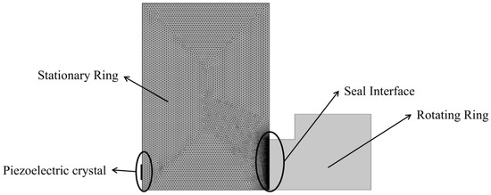
A multi-physics simulation framework considering EHL wasdeveloped to establish the mechanistic relationship between transient lubrication behavior and AE responses in mechanical seals. As illustrated in Figure 1, the numerical model focuses on the transient interaction at the seal interface between the rotating and stationary seal faces. During operation, transient pressure fluctuations are generated within the lubricated seal interface. These pressure fluctuations excite elastic waves that propagate through the stationary ring structure. Upon reaching the piezoelectric crystal, the propagating waves are converted into electrical responses through piezoelectric coupling, forming the simulated AE signal.
Figure 1.
Schematic diagram of simulation AE between matched seal interface.
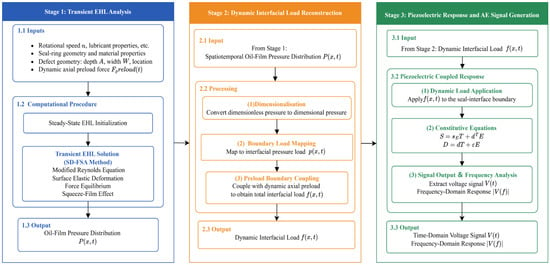
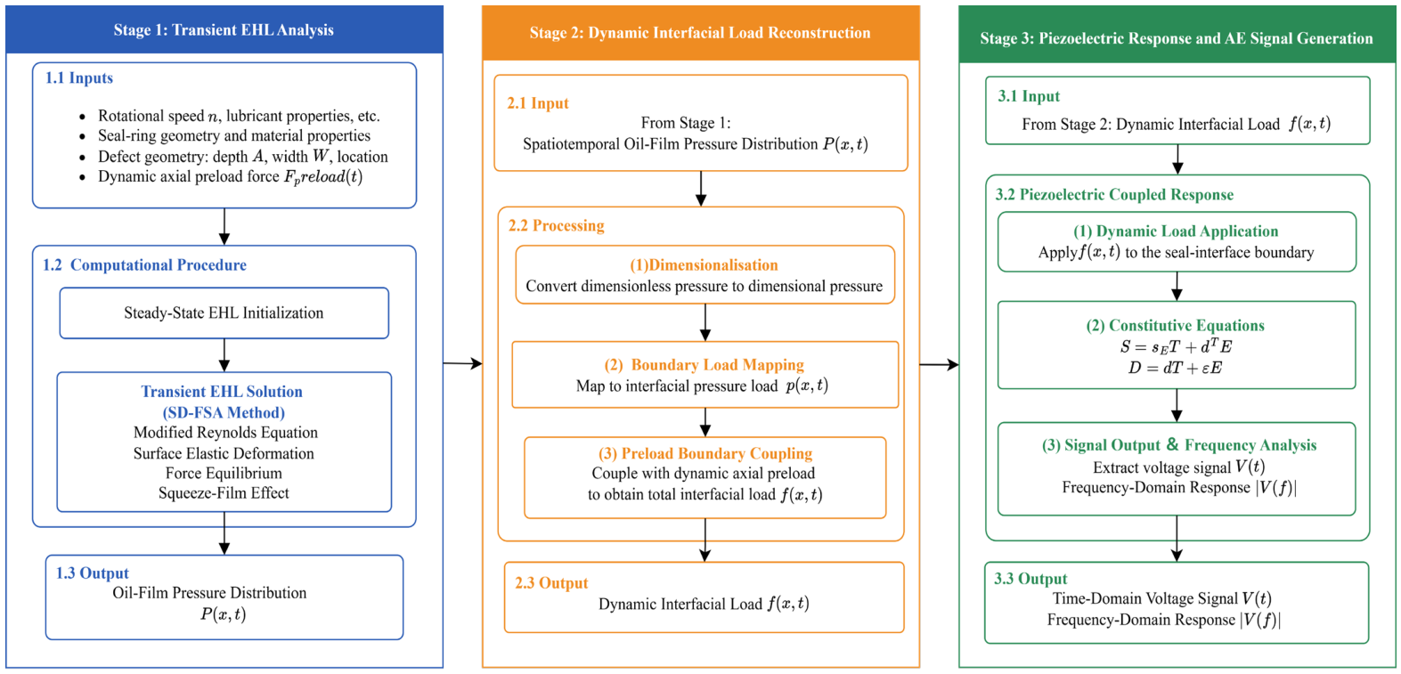
Following the physical framework illustrated in Figure 1, the numerical implementation wasorganized through a multi-stage computational procedure, as shown in Figure 2. The proposed methodology integrates EHL modelling, elastic wave propagation, and piezoelectric transduction within a unified numerical framework. Initially, the EHL model is solved to obtain the transient pressure response at the seal interface. The resultant pressure field is subsequently transferred to the structural domain through an interfacial load mapping procedure. These loading conditions excite elastic wave propagation within the stationary ring structure, and the resulting structural response is converted into voltage signals through piezoelectric coupling. This integrated framework enables the prediction of AE characteristics associated with transient interfacial lubrication behavior.
Figure 2.
Computational procedure of the proposed AE simulation method.
3.1. EHL-Based Dynamic Excitation of the Seal Interface
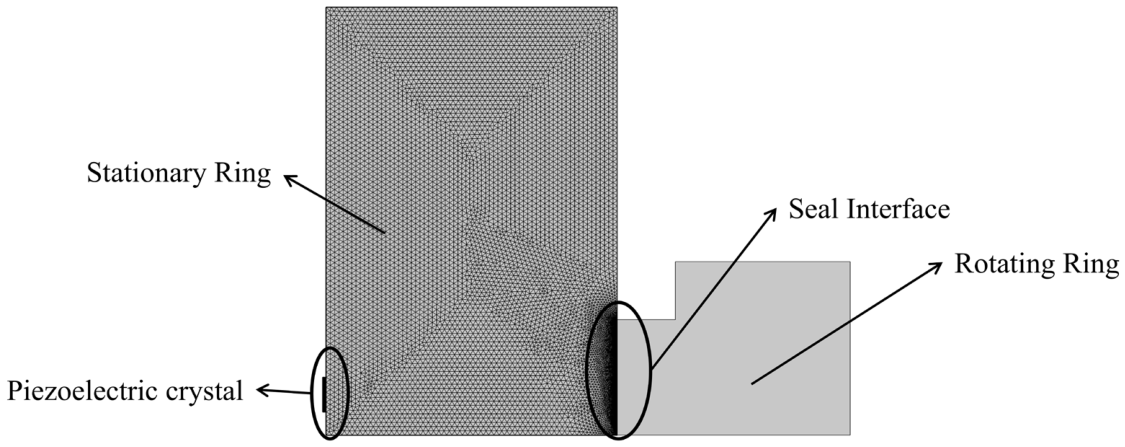
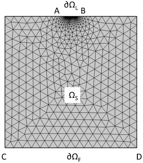
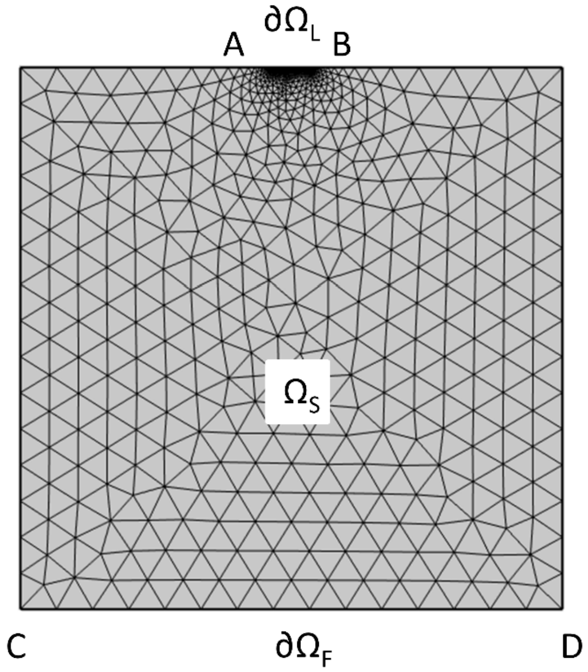
As illustrated in Figure 3, the EHL problem wasformulated within a single solid structure domain , where represents the lubrication boundary along the seal interfaceand denotes the fixed boundary. Within the SD-FSA framework, the Reynolds equation is imposed as the lubrication boundary condition on , while the solid domain is governed by the linear elasticity equations. The pressure boundary conditions at the inlet and outlet of the lubrication domain are defined according to the ambient pressure condition of the mechanical seal interface.
Figure 3.
Finite element mesh and boundary conditions for the EHL model.
The pressure generated inside the lubricated contact region produces elastic deformation of the seal faces, while the resulting deformation further modifies the local oil film thickness. Therefore, the oil film thickness is directly coupled with the structural deflection obtained from the solid mechanics solution. The normal displacement on the lubrication boundary is expressed as , where denotes the outward normal vector and represents the displacement vector obtained from the solid mechanics solution.
The structural deformation inside the solid domain is governed by the mechanical equilibrium equation , together with the constitutive relation , where is the stress tensor, is the elasticity matrix, and represents the strain tensor derived from the displacement field .
After nondimensionalization, the deformation term introduced into the oil film thickness equation is written as where is the reference radius and is the Hertzian contact half-width. The oil film thickness is then updated through the coupled interaction between lubricant pressure and structural deformation.
During the EHL solution, the pressure-induced film force is required to satisfy the external loading condition of the mechanical seal. The resultant hydrodynamic load generated by the lubricant pressure is calculated as:
where represents the resultant force generated by the lubricant pressure and denotes the externally applied mechanical load. During the iterative EHL solution, the central film thickness is adjusted until the pressure-induced load satisfies the applied loading condition.
In the numerical implementation, the penalty-based cavitation treatment was incorporated into the Reynolds equation. When the calculated pressure tends to become negative, the penalty term is activated to suppress negative pressure and maintain a physically meaningful pressure distribution.
To accurately resolve the pressure gradients and structural deformation near the seal interface, local mesh refinement is introduced around the lubrication boundary. The coupled transient EHL formulation simultaneously captures the evolution of oil film pressure and structural deformation under dynamic operating conditions. The resulting pressure field provides the interfacial loading conditions for the subsequent elastodynamic analysis.
It should be noted that the steady-state EHL solution describes the spatial distribution of the interfacial pressure field rather than a time-invariant excitation at a fixed location during operation. Due to the relative sliding motion between the rotating and stationary seal rings, the spatial pressure distribution is continuously swept across the contact interface. Therefore, for the steady-state EHL condition considered in this study, the spatial pressure field is converted into a time-dependent interfacial pressure load through a space-to-time mapping based on the relative sliding velocity. The obtained pressure history is subsequently introduced into the elastodynamic model as the lubrication-induced excitation for AE response calculation.
3.2. Elastic Wave Propagation Modelling
The time-varying interfacial pressure loads derived from the EHL analysis are subsequently applied as dynamic excitation loads on the seal interface for elastic wave simulation. In addition to the lubrication-induced pressure fluctuation, preload force acting on the seal faces is also included to represent the actual operating condition of the mechanical seal system. Under dynamic excitation, localized pressure variation inside the contact region generates stress waves that propagate through the stationary ring structure.
The elastic wave propagation inside the solid domain is governed by the dynamic equilibrium equation , where is the material density, is the displacement vector, is the stress tensor, and represents the external excitation force generated from transient pressure and preload loading. The mechanical constraints of the stationary ring are defined according to the actual assembly configuration of the mechanical seal. The material properties, mesh parameters, and temporal discretization settings used in the structural dynamic analysisare summarized in Table 1.
3.3. Piezoelectric Voltage Generation
As the elastic waves propagate through the structure, the dynamic stress transmitted through the solid domain reaches the piezoelectric crystal mounted on the outer surface of the seal structure. Through the direct piezoelectric effect, the mechanical stress generated by the propagating elastic wave is converted into an electrical voltage response.
The obtained electrical response is extracted from the piezoelectric crystal electrodes as the simulated voltage response for subsequent signal analysis. The electromechanical coupling behavior is governed by the piezoelectric constitutive equations linking mechanical strain, stress, electric displacement, and electric field. The material properties and geometric parameters of the piezoelectric crystal are summarized in Table 1.
4. Experimental Methodology and Validation
4.1. Experimental Setup and Instrumentation
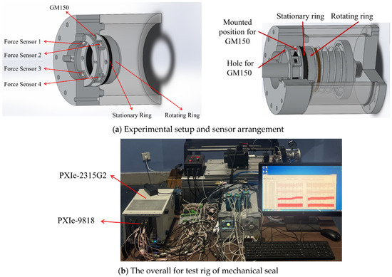
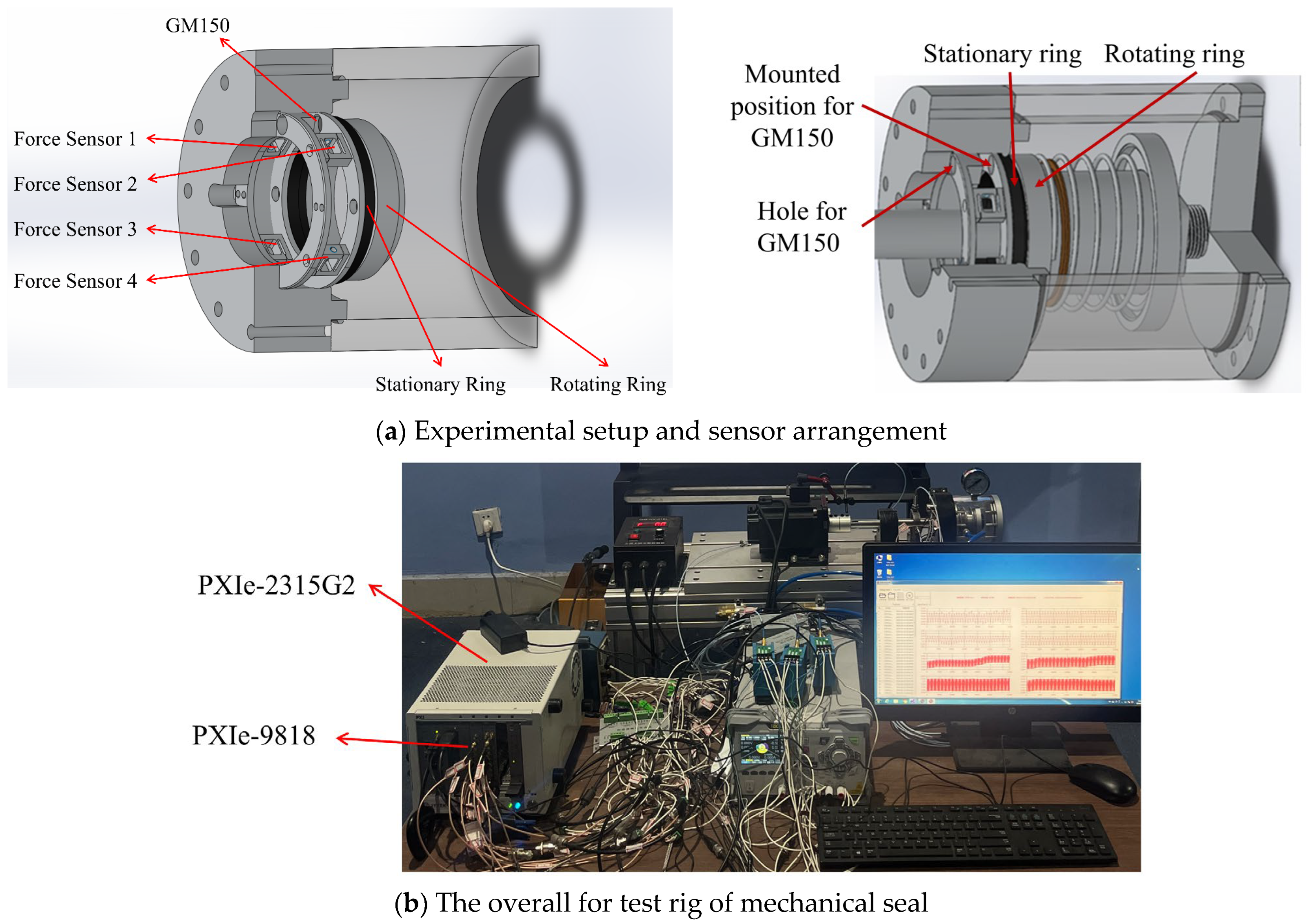
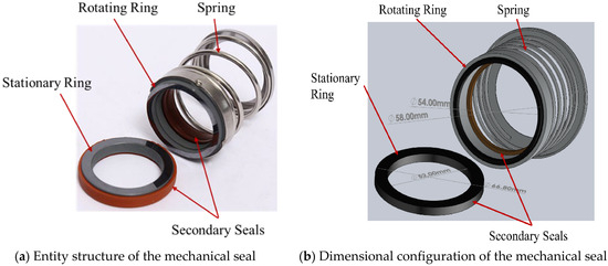
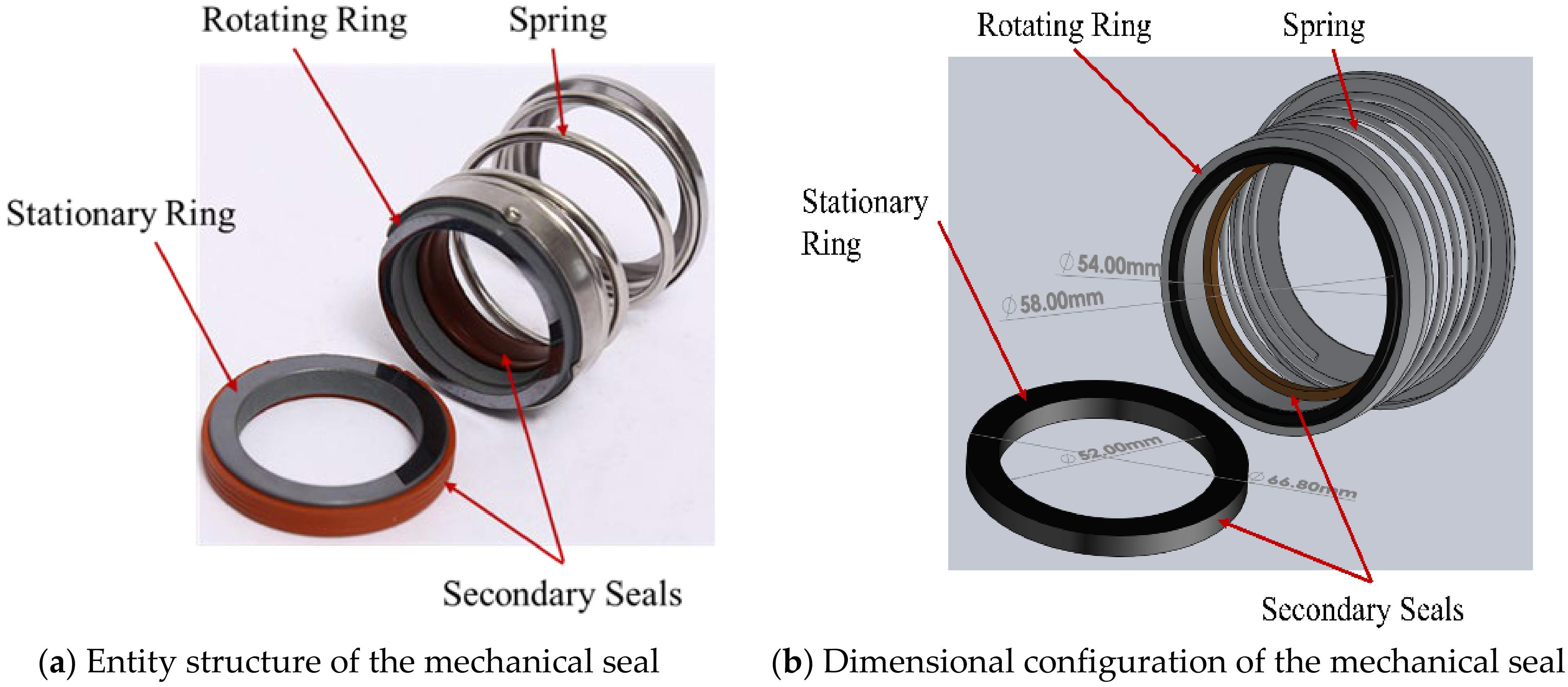
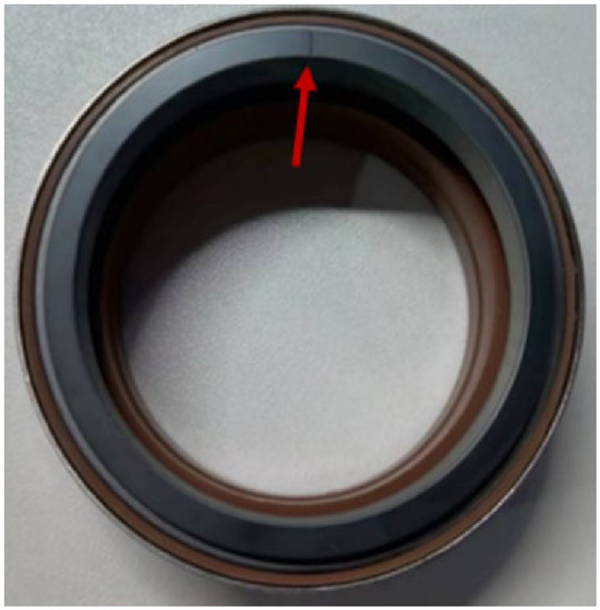
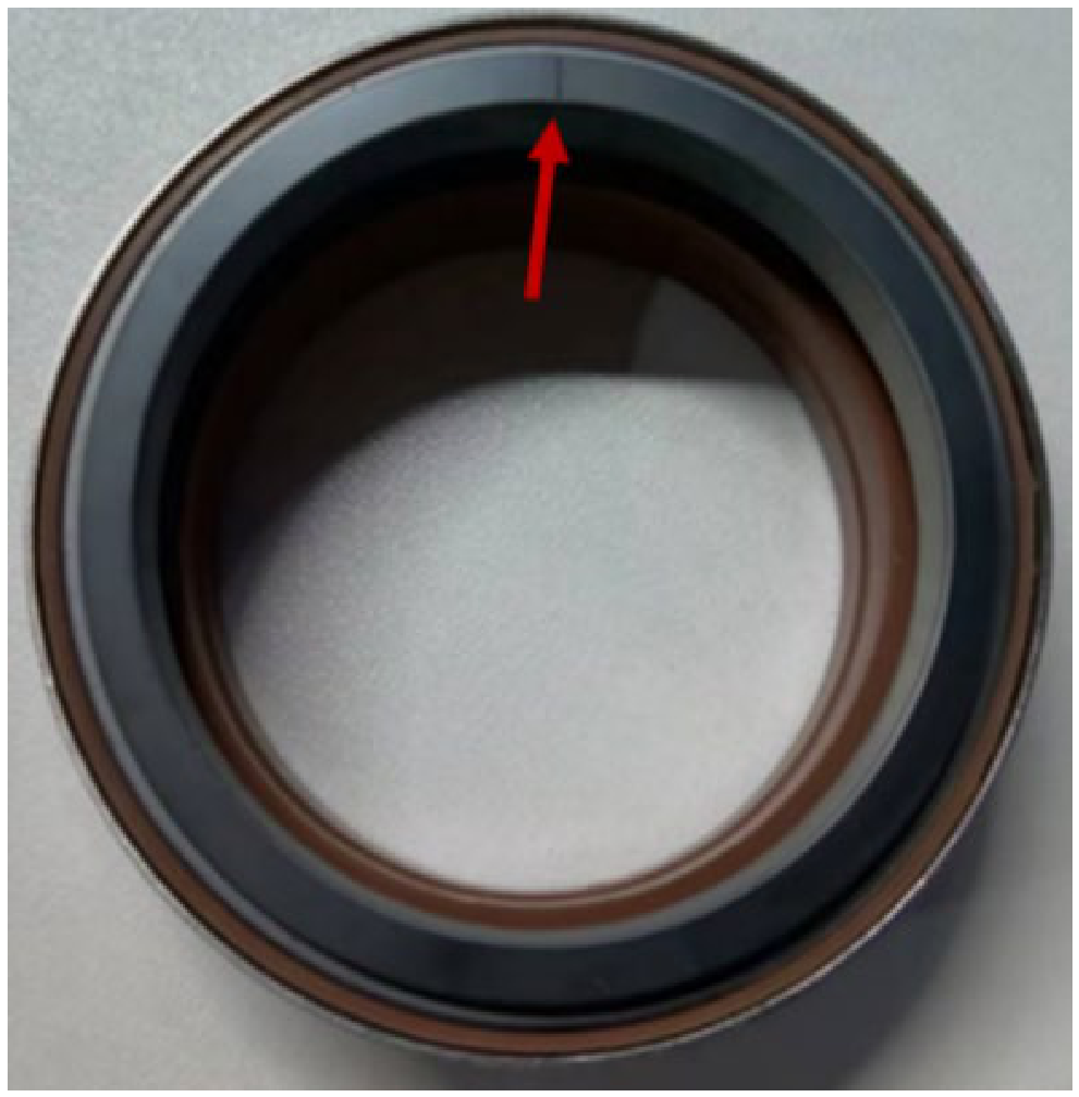
To validate the proposed simulation framework, an experimental platform was established, as illustrated in Figure 4. The test ring consists of a typical mechanical seal assembly comprising a rotating ring and a stationary ring (Figure 5). The rotating and stationary rings weremanufactured from silicon carbide and graphite, respectively. The rotating ring wasdriven at 3000 r/min. A GM150 AE sensor (bandwidth: 3–380 kHz. Qawrums Ltd., Guangzhou, China) wasmounted on the outer surface of the stationary ring to acquire AE signals generated during seal operation. Four load cells (F1–F4) wereinstalled behind the stationary ring to measure the axial preload force (Figure 4), providing experimental preload inputs for the numerical model. AE signals wererecorded using a high-speed data acquisition system at a sampling frequency of 1 MHz, with 1 million samples acquired for each measurement. Before spectral analysis, the measured AE signals were preprocessed by removing abnormal points based on the 3σ criterion and applying high-pass filtering. The preamplifier gain was set to 40 dB during signal acquisition. Defect conditions wereintroduced by machining an artificial surface defect on the rotating ring (Figure 6). Specifically, a deterministic micro-groove defect was introduced on the rotating ring surface using laser machining. The geometric parameters of the defect, including width, length, and depth, are summarized in Table 1.
Figure 4.
The test rig of mechanical seal.
Figure 5.
The test mechanical seal.
Figure 6.
Simulated faults for rotating ring. The arrow indicates the location of the micro-groove defect on the rotating ring.
4.2. Comparing Simulated AE Signal with Test Data
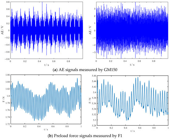
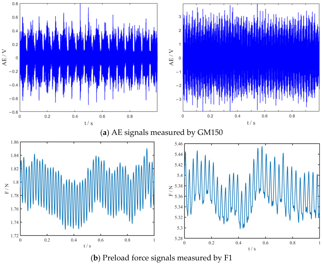
Figure 7 presents the experimentally acquired preload force and AE signals under normal and micro-groove defect conditions. The preload force signal measured by force sensor F1 was used as the input load for the numerical model (similar temporal characteristics were observed for sensors F2–F4), while the corresponding AE signals recorded by the GM150 sensor provided the experimental data for the subsequent comparison of frequency characteristics between experimental and simulated responses. Although slight variations in the measured preload force exist between the normal and defect conditions due to the dynamic operating environment, the dominant fluctuation frequencies of the measured preload signals are located in the low-frequency range (approximately 40–50 Hz), which is far below the high-frequency AE band (200–350 kHz) investigated in this study. The AE signals were continuously recorded during stable operation, and different temporal segments were examined to evaluate the consistency of the spectral characteristics.
Figure 7.
Experimental preload force and AE signals under normal and micro-groove defect conditions (normal condition on the left; micro-groove defect condition on the right).
Previous studies have reported that tribological AE activity is primarily concentrated within the high-frequency region above 200 kHz, where changes in lubrication conditions strongly influence the spectral characteristics [7]. Considering the frequency response range of the employed GM150 sensor (3–380 kHz), the spectral analysis in this study was limited to the measurable frequency range of the measurement system. Accordingly, the 200–350 kHz band was selected as the main analysis range, which covers the high-frequency AE components investigated in this study while remaining within the specified operating range of the sensor.
The spectral characteristics were obtained using fast Fourier transform (FFT) analysis of the AE signals. The experimental AE signals were processed using a record length of 1,000,000 sampling points, and a single-sided amplitude spectrum was calculated. A rectangular window was applied during FFT processing without overlap. The difference in spectral resolution, reflected by the spectral line density, between the experimental and simulated spectra is mainly due to their different signal record lengths.
The simulated response represents the voltage response generated through the AE excitation and piezoelectric conversion process. The spectral analysis focuses on the variation of high-frequency components associated with lubrication-induced excitationwithin the proposed framework.
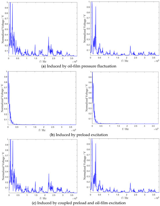
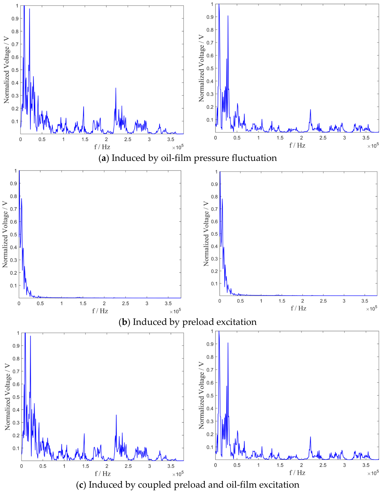
Figure 8 presents the AE spectra obtained under different excitation conditions which weresimulated using the multi-physics simulation method.
Figure 8.
Spectrum of simulated AE responses under normal and micro-groove defect condition (normal condition on the left; micro-groove defect condition on the right).
Under both normal and defect conditions, the preload excitation produces limited spectral energy within the high-frequency region. In contrast, the oil-film pressure excitation generates pronounced spectral components above 200 kHz. When preload and oil-film pressure are simultaneously applied, the resulting spectrum closely resembles that produced by the oil-film pressure excitation alone. Similar behavior is observed under both operating conditions.
To quantitatively evaluate the high-frequency spectral characteristics associated with the different excitation sources, the spectral energy within the 200–350 kHz band was calculated from the original, non-normalized spectra. The spectral energy within the selected frequency band was calculated as:
where denotes the single-sided FFT amplitude spectrum and is the frequency resolution. The relative spectral energy ratios of the oil-film pressure excitation and preload excitation with respect to the coupled excitation were then calculated as:
The calculated relative spectral energy ratios are summarized in Table 2.
Table 2.
Relative spectral energy ratios of individual excitation responses to the coupled response in the 200–350 kHz band.
Under the normal condition, the relative spectral energy ratio of the oil-film pressure excitation is 98.73%, whereas that of the preload excitation is 0.103%. Under the micro-groove defect condition, the corresponding ratios are 95.02% and 0.270%, respectively. These results demonstrate that the high-frequency spectral characteristics of the coupled response are predominantly associated with the oil-film pressure excitation, while the relative spectral energy of the preload excitation is comparatively small within the investigated frequency band.
The comparison of the experimental and simulated AE spectra under normal and defect operating conditions is shown in Figure 9.
Figure 9.
Spectral comparison of simulated and experimental AE signals under normal and micro-groove defect conditions (normal condition on the left; micro-groove defect condition on the right).
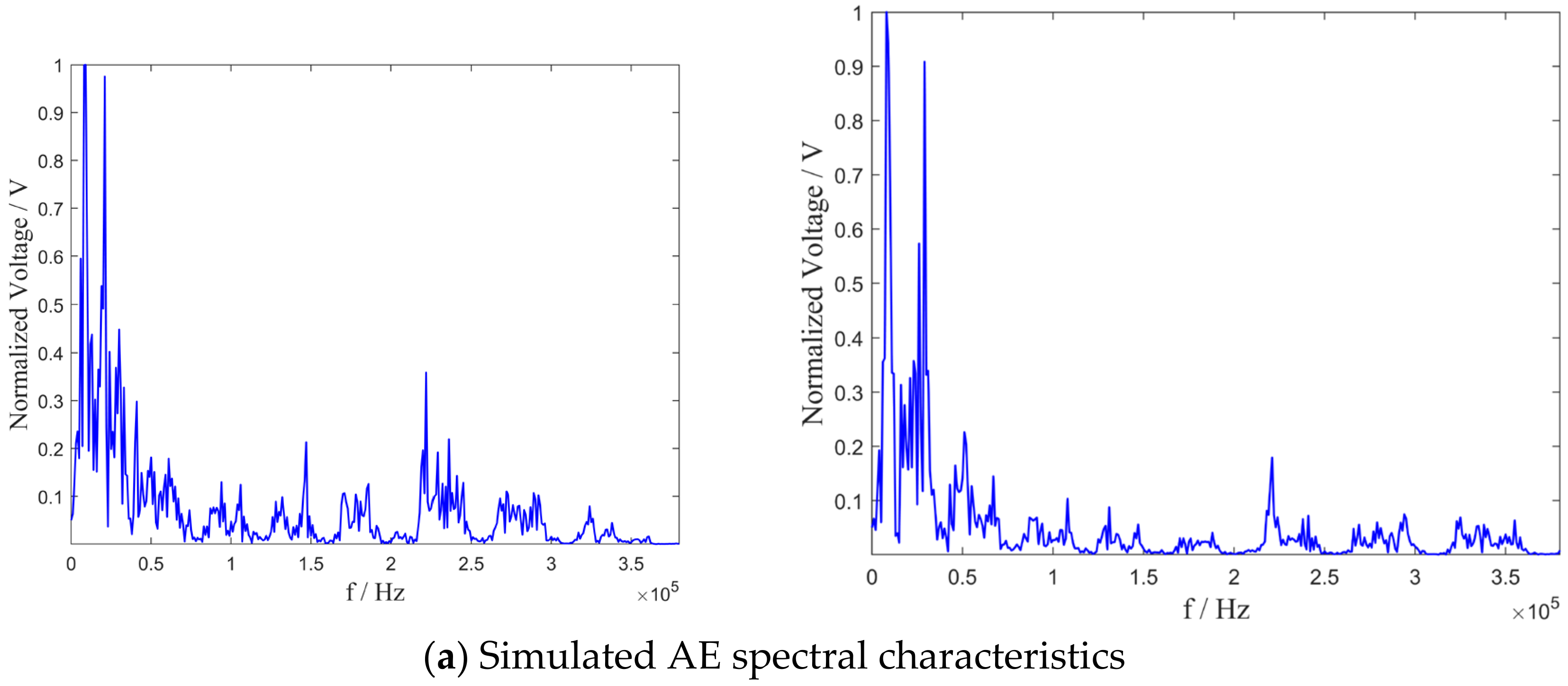
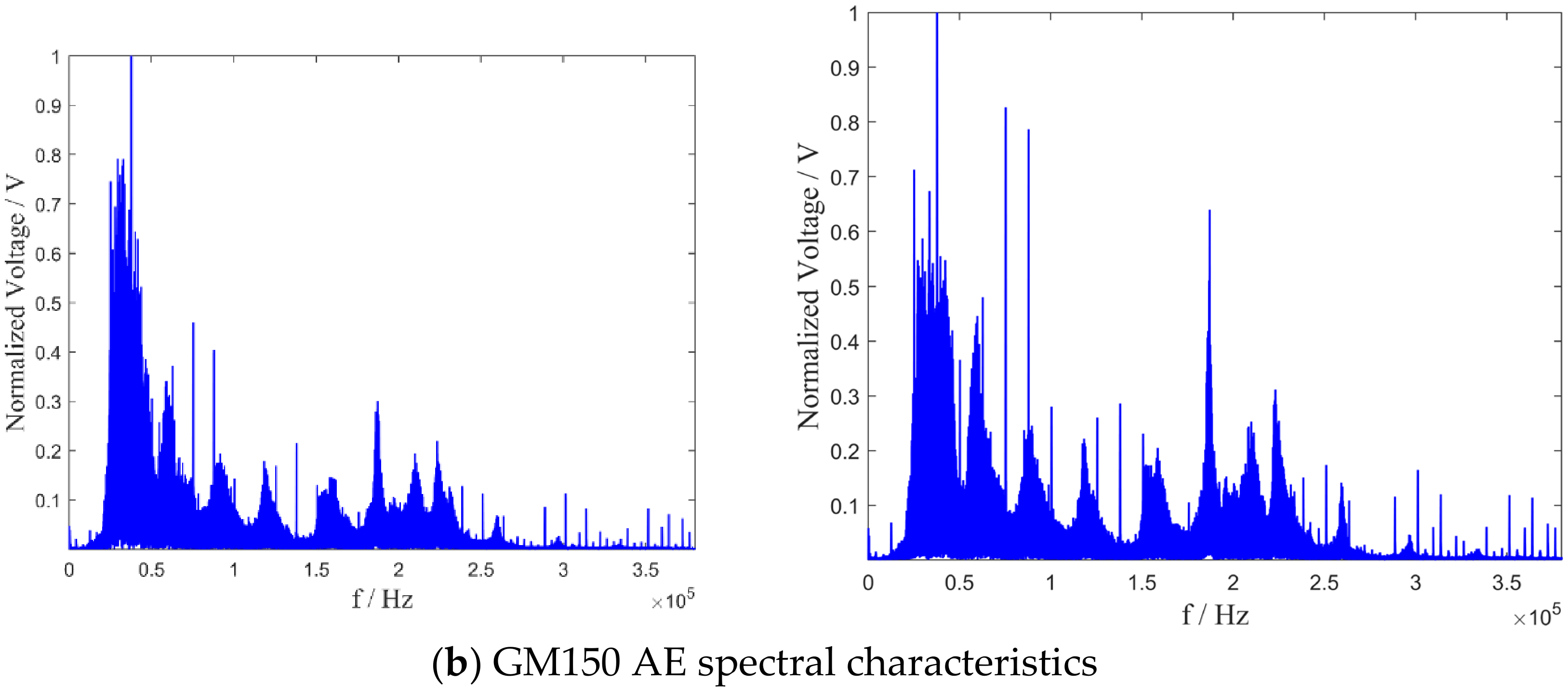
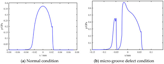
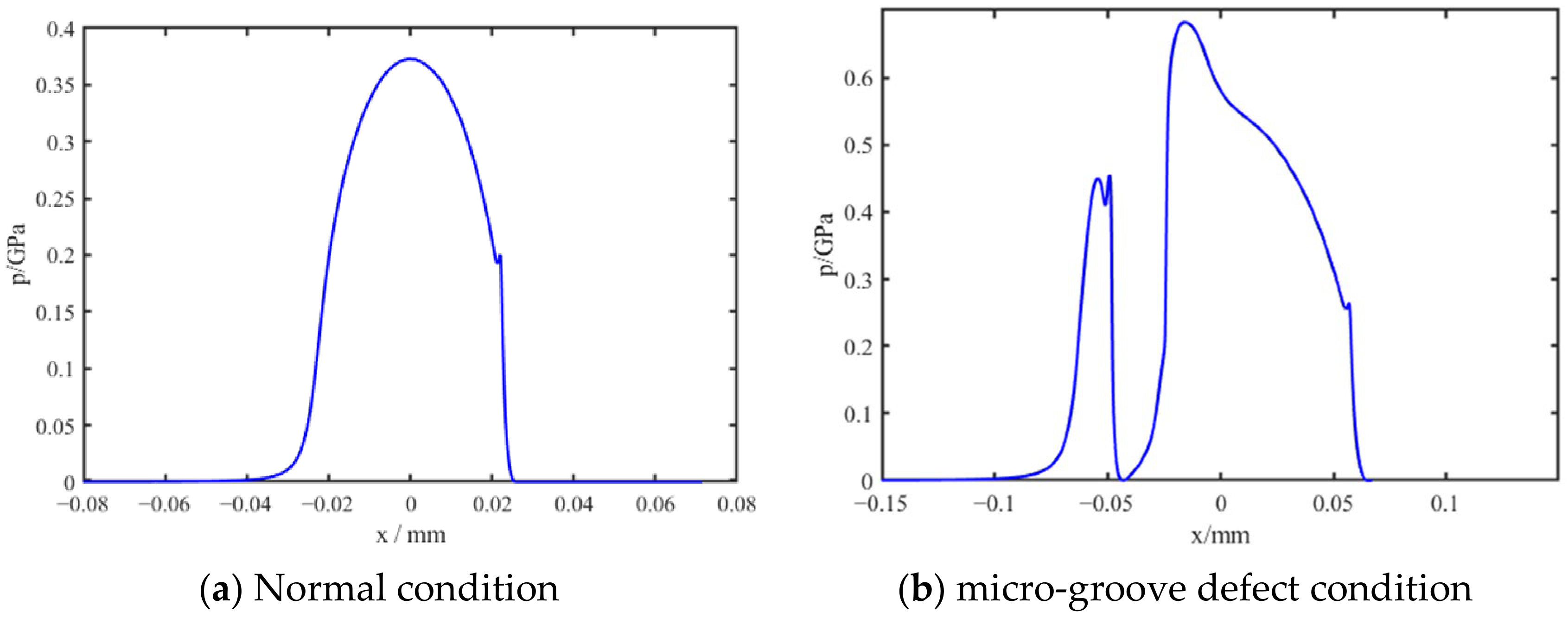
Under the normal condition, the simulated spectrum exhibits relatively weak and sparsely distributed high-frequency components above 200 kHz, and the dominant energy within the high-frequency region is concentrated near its lower-frequency end. The corresponding oil-film pressure distribution, shown in Figure 10a secondary pressure peak near the outlet, commonly referred to as the Petrusevich pressure spike in EHL contacts, was observed, indicating the consistency of the calculated pressure distribution with classical EHL characteristics. Under the defect condition, the simulated high-frequency AE components are stronger, more broadly distributed, and extend to higher frequencies. The oil-film pressure distribution in this state exhibits pronounced local perturbations surrounding the defect region. The enhanced local fluctuations provide a potential dynamic mechanism underlying the high-frequency AE increase. Comparison with the experimental spectra reveals a similar pattern: the defect condition produces stronger and broader high-frequency components than the normal condition.
Figure 10.
Interfacial oil film pressure distributions under normal and micro-groove defect conditions.
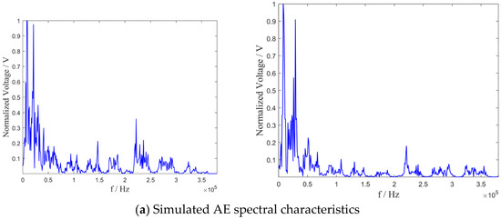
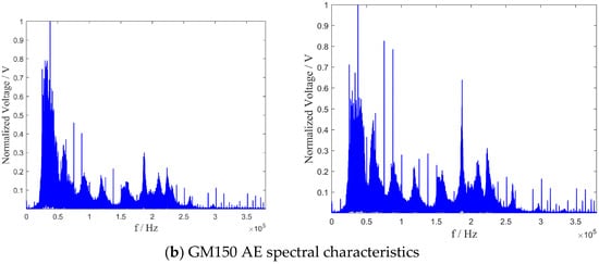
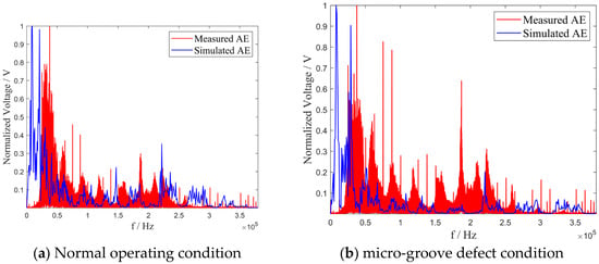
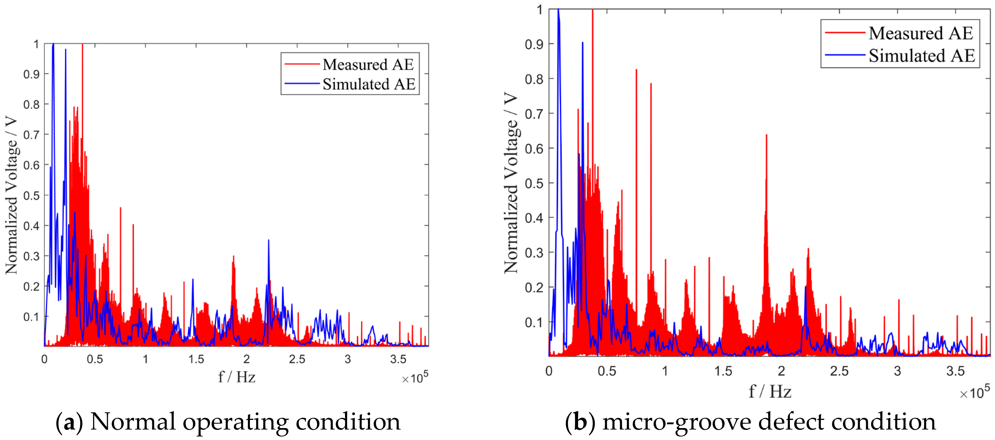
The comparison of the simulated and experimental AE signals under normal and defect conditionsisshown in Figure 11.
Figure 11.
Spectral comparison between simulated AE and GM150 measurements.
The simulated and experimental spectra show qualitatively consistent variation tendencies under both operating conditions. The simulated spectra exhibit similar spectral trends to those observed in the measurements, including the enhanced high-frequency spectral activity and the broader spectral distribution under defect conditions.
4.3. Physical Evolution of Elastic Wave Propagation
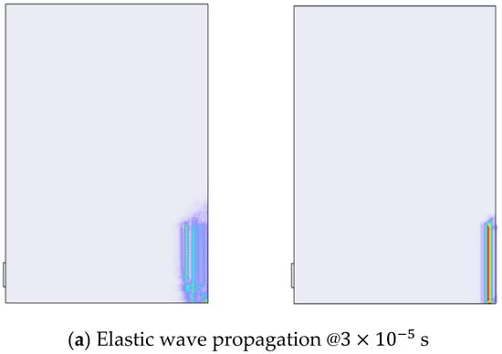
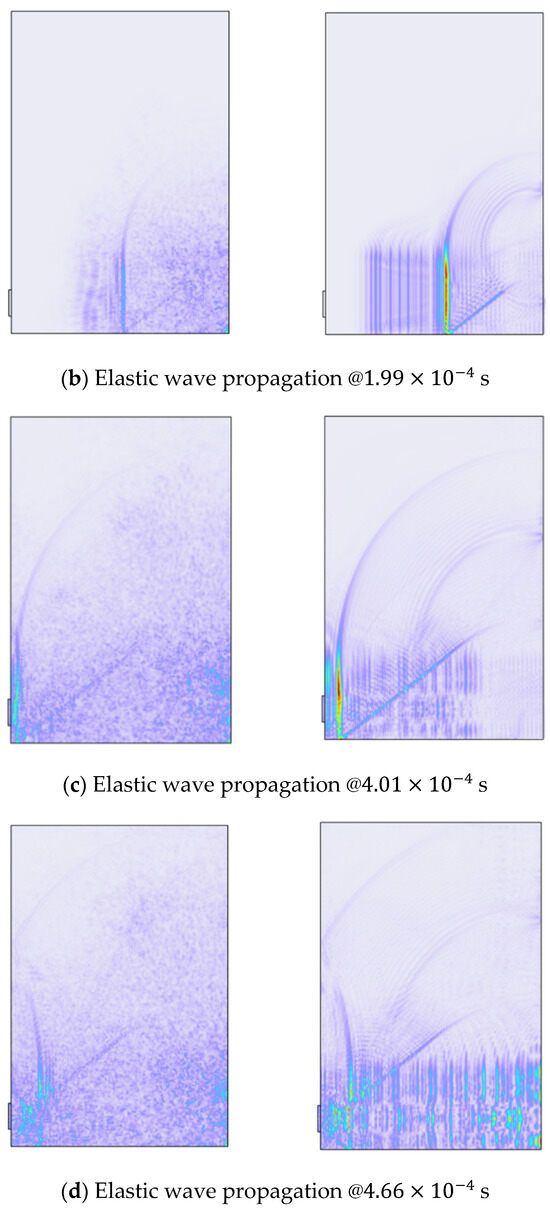
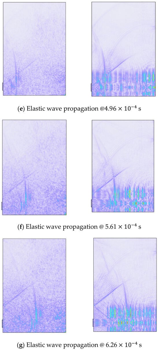
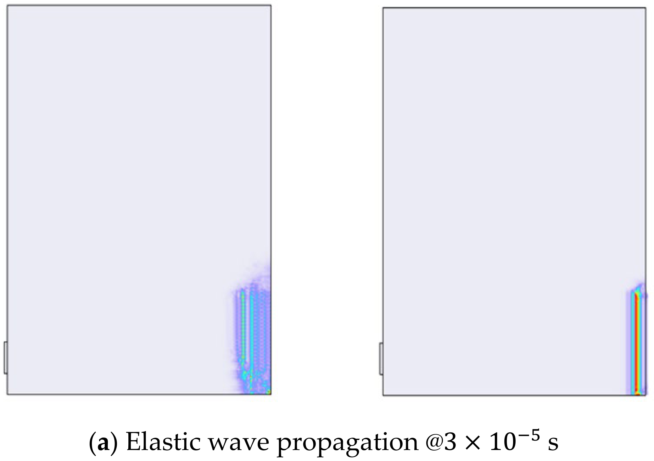
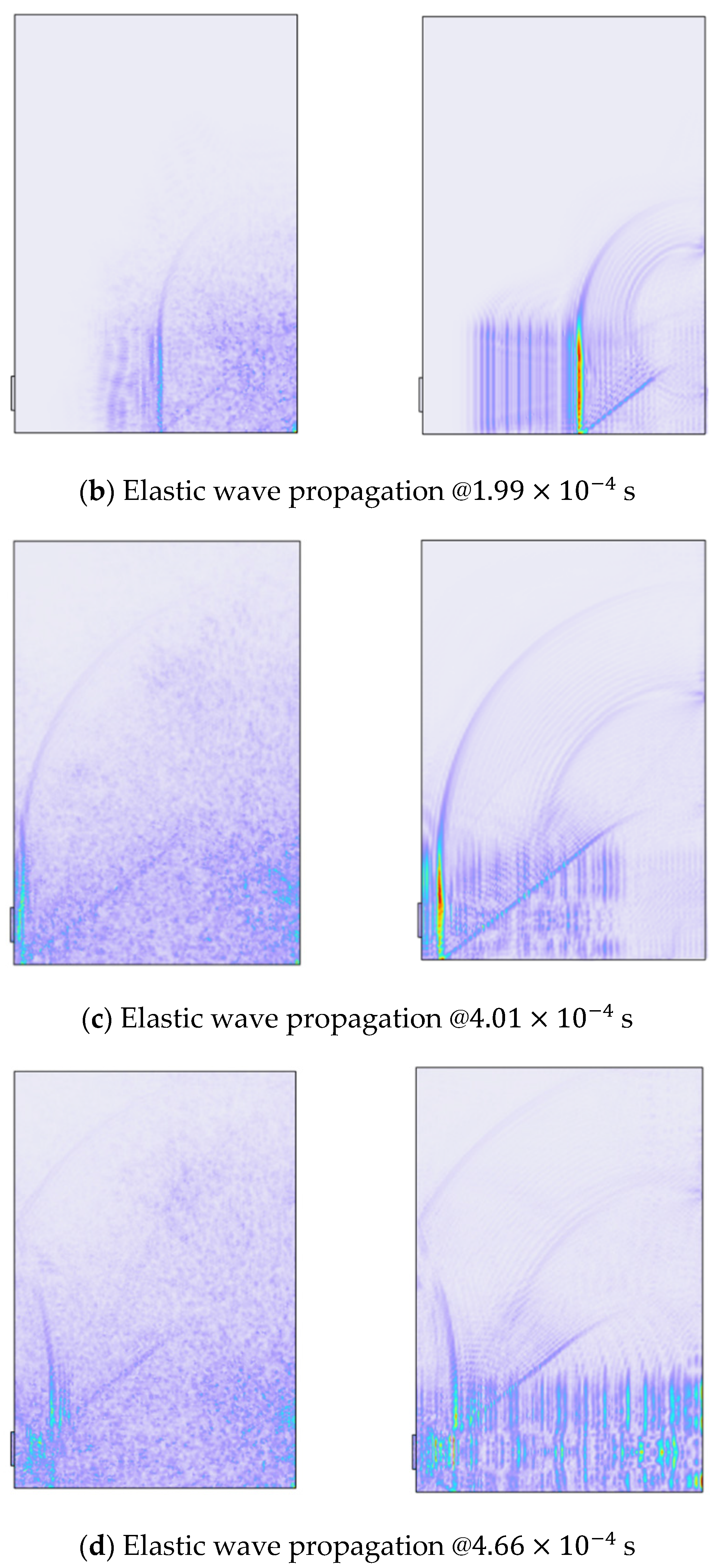
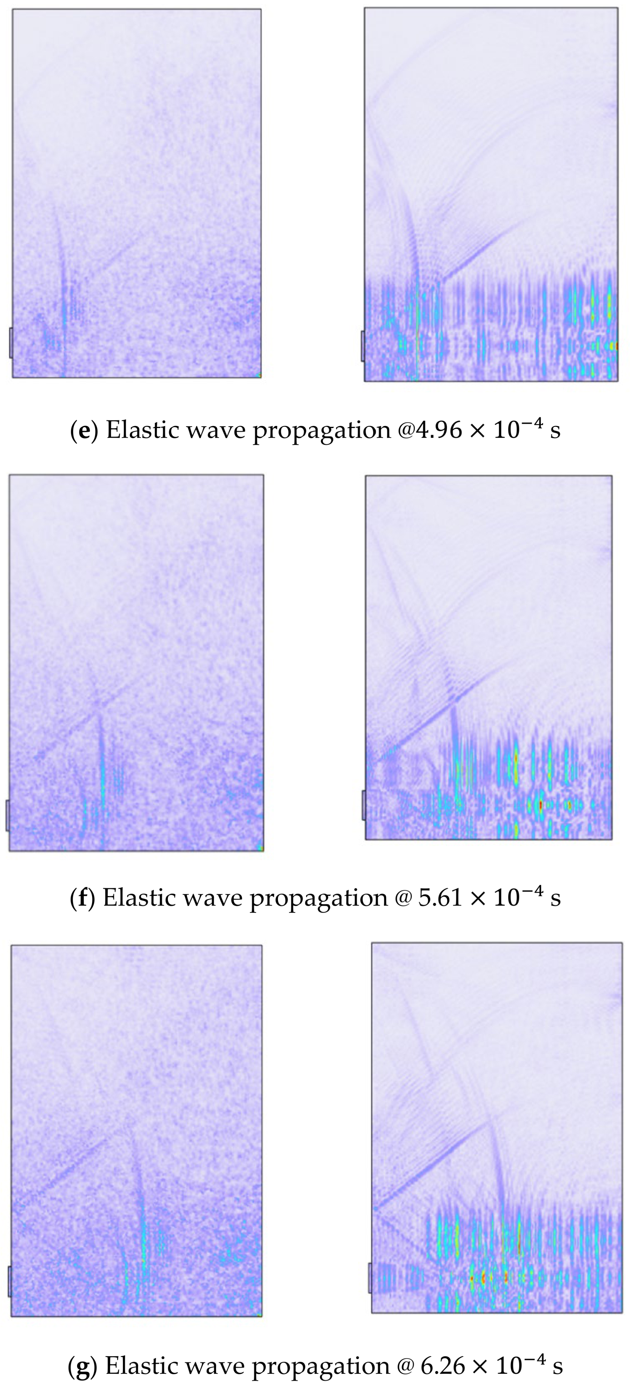
The spatiotemporal evolution of elastic wave propagation in the stationary ring is illustrated in Figure 12. Under normal operating conditions, the elastic waves propagate smoothly from the excitation region with gradual wavefront expansion and attenuation. In contrast, the micro-groove defect condition exhibits intensified local wave activity and stronger elastic wave concentration during propagation. As the wave field evolves over time, the defect-induced excitation generates more pronounced transient disturbances and more complex propagation patterns in the structure.
Figure 12.
Spatiotemporal evolution of elastic wave propagation under normal and micro-groove defect conditions (normal condition on the left; micro-groove defect condition on the right). The color scale indicates the stress magnitude in the stationary ring.
5. Conclusions
A physics-based multi-physics simulation framework incorporating EHL effects was developedto investigate AE generation in mechanical seals. The results demonstrate that oil-film pressure excitation can generate high-frequency AE responses above 200 kHz within the proposed framework, while preload excitation contributes limited spectral energy within this frequency range. Under defect conditions, enhanced oil-film pressure perturbations are accompanied by stronger and broader high-frequency AE responses. Comparison with experimental measurements indicates similar high-frequency spectral characteristics under both normal and defect conditions.
It should be noted that the present study focuses on the possible contribution of lubrication-induced excitation under EHL conditions. Other potential AE sources associated with defect-induced mechanical impacts, cavitation dynamics, or structural resonance were not separately isolated in the current experimental configuration. Further investigations involving controlled baseline tests are required to distinguish these contributions.
Author Contributions
Conceptualization, X.Z.; methodology, B.Z. and X.Z.; software, C.H., J.W. and Z.S.; data curation, B.Z., S.L., J.W., Z.S. and C.H.; writing—original draft preparation, C.H., Z.S. and J.W.; writing—review and editing, X.Z., R.S. and B.Z.; supervision, X.Z.; funding acquisition, B.X. All authors have read and agreed to the published version of the manuscript.
Funding
This research wassupported by the Science and Technology Project of Henan (242102220071).
Data Availability Statement
The raw data supporting theconclusions of this article are available on request from the corresponding author. No publicly archived datasets were generated within this theoretical and numerical simulation research.
Conflicts of Interest
The authors declare that they have no known competing financial interests or personal relationships that could have appeared to influence the work reported in this paper.
References
- Bi, H.; Hao, M.; Li, Q.; Ren, B.; Xu, W.; Sun, X. Investigation of the tribological behaviour of mechanical seals based on acoustic emission characteristics. Appl. Acoust. 2025, 237, 110769. [Google Scholar] [CrossRef] [Scilit]
- Fan, Y.E.; Gu, F.; Ball, A. A Review of the Condition Monitoring of Mechanical Seals. In Proceedings of the ASME 7th Biennial Conference on Engineering Systems Design and Analysis, Manchester, UK, 19–22 July 2004; Volume 3, pp. 179–184. [Google Scholar]
- Towsyfyan, H.; Gu, F.; Ball, A. A Review of Mechanical Seals Tribology and Condition Monitoring. In Proceedings of the Computing and Engineering Annual Researchers’ Conference2013: (CEARC13), Huddersfield, UK, 16–18 December 2013; pp. 200–205. [Google Scholar]
- Wang, Q.; Song, Y.; Li, H.; Shu, Y.; Xiao, Y. Tribological Behavior Characterization and Fault Detection of Mechanical Seals Based on Face Vibration Acceleration Measurements. Lubricants 2023, 11, 430. [Google Scholar] [CrossRef] [Scilit]
- Mba, D. Development of Acoustic Emission Technology for Condition Monitoring and Diagnosis of Rotating Machines: Bearings, Pumps, Gearboxes, Engines, and Rotating Structures. Shock. Vib. Dig. 2006, 38, 3–16. [Google Scholar] [CrossRef] [Scilit]
- Tan, C.K.; Mba, D. Correlation Between Acoustic Emission Activity and Asperity Contact During Meshing of Spur Gears Under Partial Elastohydrodynamic Lubrication. Tribol. Lett. 2005, 20, 63–67. [Google Scholar] [CrossRef] [Scilit]
- Towsyfyan, H.; Gu, F.; Ball, A.D.; Liang, B. Tribological behaviour diagnostic and fault detection of mechanical seals based on acoustic emission measurements. Friction 2019, 7, 572–586. [Google Scholar] [CrossRef] [Scilit]
- Lebeck, A.O. Principles and Design of Mechanical Face Seals; Wiley-Interscience: New York, NY, USA, 1992. [Google Scholar]
- Dowson, D.; Higginson, G.R. Chapter 12—Analysis of Roller Bearings. In Elasto-Hydrodynamic Lubrication; Dowson, D., Higginson, G.R., Eds.; Pergamon: Oxford, UK, 1977; pp. 193–215. [Google Scholar]
- Lohner, T.; Ziegltrum, A.; Stemplinger, J.P.; Stahl, K. Engineering Software Solution for Thermal Elastohydrodynamic Lubrication Using Multiphysics Software. Adv. Tribol. 2016, 2016, 6507203. [Google Scholar] [CrossRef] [Scilit]
- Towsyfyan, H.; Gu, F.; Ball, A.D.; Liang, B. Modelling acoustic emissions generated by tribological behaviour of mechanical seals for condition monitoring and fault detection. Tribol. Int. 2018, 125, 46–58. [Google Scholar] [CrossRef] [Scilit]
- Sadegh, H.; Mehdi, A.N.; Mehdi, A. Classification of acoustic emission signals generated from journal bearing at different lubrication conditions based on wavelet analysis in combination with artificial neural network and genetic algorithm. Tribol. Int. 2016, 95, 426–434. [Google Scholar] [CrossRef] [Scilit]
- Towsyfyan, H.; Wei, N.; Gu, F.; Ball, A. Identification of Lubrication Regimes in Mechanical Seals Using Acoustic Emission for Condition Monitoring. In Proceedings of the54th Annual Conference of The British Institute of Non-Destructive Testing BINDT, Telford, UK, 8–10 September 2015. [Google Scholar]
- Mba, D.; Roberts, T.; Taheri, E.; Roddis, A. Application of acoustic emission technology for detecting the onset and duration of contact in liquid lubricated mechanical seals. Insight-Non-Destr. Test. Cond. Monit. 2006, 48, 486–487. [Google Scholar] [CrossRef] [Scilit]
- Towsyfyan, H.; Raharjo, P.; Gu, F.; Ball, A. Characterization of Acoustic Emissions from Journal Bearings for Fault Detection. In Proceedings of the 52nd Annual Conference of the British Institute of Non-Destructive Testing 2013, Telford, UK, 10–12 September 2013; pp. 92–103. [Google Scholar]
- Rogers, L.M. The application of vibration signature analysis and acoustic emission source location to on-line condition monitoring of anti-friction bearings. Tribol. Int. 1979, 12, 51–58. [Google Scholar] [CrossRef] [Scilit]
- Márquez, F.P.G.; Tobias, A.M.; Pérez, J.M.P.; Papaelias, M. Condition monitoring of wind turbines: Techniques and methods renewable energy source. Renew. Energy 2012, 46, 169–178. [Google Scholar]
- Toutountzakis, T.; Tan, C.K.; Mba, D. Application of acoustic emission to seeded gear fault detection. NDT E Int. 2005, 38, 27–36. [Google Scholar] [CrossRef] [Scilit]
- Fan, Y.; Gu, F.; Ball, A. Modelling acoustic emissions generated by sliding friction. Wear 2010, 268, 811–815. [Google Scholar] [CrossRef] [Scilit]
- Sharma, R.B.; Parey, A. Modelling of acoustic emission generated in rolling element bearing. Appl. Acoust. 2019, 144, 96–112. [Google Scholar] [CrossRef] [Scilit]
- Patil, A.P.; Mishra, B.K.; Harsha, S.P. Vibration based modelling of acoustic emission of rolling element bearings. J. Sound Vib. 2020, 468, 115117. [Google Scholar] [CrossRef] [Scilit]
- Sharma, R.B.; Parey, A.; Tandon, N. Modelling of acoustic emission generated in involute spur gear pair. J. Sound Vib. 2017, 393, 353–373. [Google Scholar] [CrossRef] [Scilit]
- Wang, C.; Qi, H.; Hou, D.; Han, D. Coupled vibration—Acoustic emission model for high-speed train bearings with local defects. Appl. Acoust. 2024, 224, 110142. [Google Scholar] [CrossRef] [Scilit]
- Habchi, W.; Eyheramendy, D.; Vergne, P.; Morales-Espejel, G. A Full-System Approach of the Elastohydrodynamic Line/Point Contact Problem. J. Tribol. 2008, 130, 021501. [Google Scholar] [CrossRef] [Scilit]
- Habchi, W. A Full-System Finite Element Approach to Elastohydrodynamic Lubrication Problems: APPLICATION to Ultra-Low-Viscosity Fluids. Ph.D. Thesis, University of Lyon, Lyon, France, 2008. [Google Scholar]
- Larsson, R. Modelling the effect of surface roughness on lubrication in all regimes. Tribol. Int. 2009, 42, 512–516. [Google Scholar] [CrossRef] [Scilit]
- Isaksson, P.; Nilsson, D.; Larsson, R. Elasto-hydrodynamic simulation of complex geometries in hydraulic motors. Tribol. Int. 2009, 42, 1418–1423. [Google Scholar] [CrossRef] [Scilit]
- Tan, X.; Goodyer, C.E.; Jimack, P.K.; Taylor, R.I.; Walkley, M.A. Computational approaches for modelling elastohydrodynamic lubrication using multiphysics software. Proc. Inst. Mech. Eng. Part J J. Eng. Tribol. 2012, 226, 463–480. [Google Scholar] [CrossRef] [Scilit]
- Yang, P.; Wen, S.A. Generalized Reynolds Equation for Non-Newtonian Thermal Elastohydrodynamic Lubrication. J. Tribol. 1990, 112, 631–636. [Google Scholar] [CrossRef] [Scilit]
- Venner, C.H.; Lubrecht, A.A.; Napel, W.E. Numerical Simulation of the Overrolling of a Surface Feature in an EHL Line Contact. J. Tribol. 1991, 113, 777–783. [Google Scholar] [CrossRef] [Scilit]
- ANSI/IEEE Std 176-1987; IEEE Standard on Piezoelectricity. IEEE: New York, NY, USA, 1988.
- Kaltenbacher, M. Numerical Simulation of Mechatronic Sensors and Actuators; Springer: Berlin/Heidelberg, Germany, 2007. [Google Scholar]

Disclaimer/Publisher’s Note: The statements, opinions and data contained in all publications are solely those of the individual author(s) and contributor(s) and not of MDPI and/or the editor(s). MDPI and/or the editor(s) disclaim responsibility for any injury to people or property resulting from any ideas, methods, instructions or products referred to in the content. |
© 2026 by the authors. Licensee MDPI, Basel, Switzerland. This article is an open access article distributed under the terms and conditions of the Creative Commons Attribution (CC BY) license.