


Abstract
Despite the extensive research that has been carried out on alternative liquid lubricants for extrusion processes, it remains challenging to apply liquid lubricants to forms involving long components, such as rotor shafts, which undergo substantial surface expansion. In this study, a continuous lubrication method is proposed, in which lubricant is sealed into the extrusion die using a counterpunch. The negative pressure generated by the punch pulse motion during processing is utilised, and this is applied to the forward extrusion of a two-step shaft profile. The clearance between the container and the billet has a significant impact on the pooling of the lubricant within the extrusion die. It was established that, at a die half-angle of 15°, the maximum load was reduced by 15% at a billet diameter of 9.85 mm for a container diameter of 10 mm. A comparison of load–stroke diagrams from finite element method (FEM) simulations shows that the coefficient of friction (μ) decreased to approximately 0.05–0.1 during reloading and increased to a maximum of approximately 0.12 during loading. It was determined that the die half-angle of 30° resulted in a shorter sliding distance within the die than the 15° angle. This finding enables the suppression of the increase in friction. The findings of the FEM analysis substantiate the notion that material influx into the undercut area exerts an influence on relubrication.
1. Introduction
To reduce CO2 emissions, the electrification of small special-purpose vehicles and agricultural machinery is progressing [1]. Compared to automotive parts, these are produced in a wide variety of types but in small quantities. In cold processing, including extrusion, lubrication between the material and the die is extremely important. The mainstream method is a chemical treatment called bonderising, which applies a phosphate coating to the material’s surface and forms a film prior to the forming process. However, issues such as reduced dimensional accuracy, the need for larger equipment, and environmental concerns related to the generation of large amounts of industrial waste and wastewater have become problematic.
Much research has been conducted on lubricants as alternatives to bonderising in forging processes. Monaghan et al. [2] investigated the effects of lubricants on surface properties, while Lazzarotto et al. [3] demonstrated the measurement of friction coefficients applicable to forward extrusion using liquid lubricants via the upsetting-sliding test and validated this method. Komatsuzaki et al. [4] conducted a study in which they examined the effects of the addition of extreme pressure agents to the lubricant in the process of forward extrusion. Gariety et al. [5] conducted a study in which they evaluated commercially available lubricants, including MEC Homat, Daido AquaLub, and MCI Z-Coat. Caminag a et al. [6] evaluated liquid lubricants using a device capable of supplying lubricant from the bottom of a container. Syahrullail et al. [7] conducted forward extrusion evaluations using palm oil.
In addition, it has been demonstrated that the application of micro-texturing [8,9] to tools for the pooling of lubricant leads to an extension of tool life during backward extrusion. Furthermore, Abe et al. [10] demonstrated that the addition of ceramic particles to lubricating oil results in alterations in surface roughness after forward extrusion and in hardness, the latter being contingent on the size of the particles. Furthermore, Chen et al. [11] obtained the shear friction factor m through the utilisation of blasting-like lubrication. In order to reduce load, Mousavi et al. [12] applied ultrasonic vibration to forward extrusion, while Wan et al. [13] applied it to micro-extrusion, thereby demonstrating that load could be reduced.
Concurrently, since approximately the year 2000, servo presses have become pervasive, and a substantial body of research utilising pulse motion has been undertaken [14]. As posited by Maeno et al. [15], the utilisation of pulse motion to upset aluminium alloy sheets resulted in a reduction of friction during processing, consequently decreasing the processing load. Furthermore, the occurrence of a relubrication effect was attributed to the disparity in elastic deformation between the material and the die during pulsation. Furthermore, Matsumoto et al. [16,17] reported that in the process of backward extrusion, the application of a pulse motion using a punch with lubrication holes allows for the supply of lubricating oil and the creation of deep holes. Maeno et al. [18] reported on the relubrication effect of liquid lubricants in cup forming using a punch with dimples on its bottom during reverse extrusion with a pulsed motion. Maeno et al. [19] and Soleymanipoor et al. [20] reported on the relubrication effect of pulse motion in inner spline forming by backward extrusion. Similar effects were reported by Ma et al. [21] and Groche et al. [22] in spline forming; Yanagida et al. [23] in spur gear forming; and Matsumoto et al. [24] in the press-fitting of hollow cylindrical materials. Ben et al. [25] verified the effects of pulse motion through a combination of experimental methods and finite element analysis (FEM). This was achieved by conducting a T-shape compression test, which incorporates both compression and forward extrusion regions. In the study by Behrens et al. [26], the impact of superimposed oscillation on forward extrusion with the utilisation of a liquid lubricant (Variol OFP 1007) was examined. The findings indicated that the maximum load exhibited a 2% reduction when subjected to an oscillatory force of 300 Hz. Matsumoto et al. [27] demonstrated, based on direct observation of the interface during forging with a forward extrusion section, that the lubricant was thickened by approximately 1–10 μm between the start of the ram retreat and the re-start of forging at each pulsation. Moreover, Okumura et al. [28] demonstrated that the forward extrusion process can be modified by incorporating a Frequency Modulated (FM) forming technique, whereby the die is oscillated during the forming operation. This modification resulted in a reduction of the forming load. However, it is important to note that this reduction in load is not attributable to the lubrication effect, but rather to the deformation caused by the oscillatory motion of the die. Yahaya et al. [29] reported that by arranging dimples with a diameter of 0.6 mm in a lattice pattern on the tapered section of a plane strain forward extrusion die, it was possible to reduce friction to a level comparable to that achieved with high viscosity lubricants, even when using low viscosity lubricants. Kuhn et al. [30] demonstrated that by using a lubricant containing a thermochromic indicator in a multi-stage forward axis rear cup process, the maximum post-processing surface temperature could be identified within the range of 220–260 °C. Despite the existence of numerous studies that have examined the use of vibrational motion or dimples to reduce friction in forward extrusion, the resulting reduction in load is minimal.
In this study, a continuous lubrication method was developed for application to long components, such as rotor shafts, where the use of liquid lubricants is difficult. This method serves as an alternative to bonderising on the material’s surface, and it has been shown to achieve a greater load reduction effect in comparison with conventional forward extrusion. The method under discussion involves the sealing of a low-viscosity liquid lubricant (synthetic oil) within the die during the process of forward extrusion. From the perspective of environmental impact, research is also underway on biodegradable, plant-derived lubricants based on palm oil. The lubricating properties of the lubricant have been the subject of evaluation in a number of forming processes, including extrusion [29], forging [31], and cold rolling [32,33]. The results of these evaluations indicate that the lubricant performs to a level that is equivalent to, or in some cases superior to, that of conventional mineral oil-based lubricants. In this study, conventional mineral oil-based synthetic oil was utilised to evaluate the developed method. The utilisation of the relubrication effect, which is caused by the negative pressure that is generated by the amplitude of the punch during the processing of the material, is also a key element of the method. It has been demonstrated that the relubrication process has a dual function; firstly, it serves to inhibit the deterioration of surface quality during processing, and secondly, it prevents further deterioration during knockout. It is evident that the absence of any necessity for special tool modifications [6,16,19,29] to introduce lubrication renders this method applicable not only to forward extrusion but also to plastic forming processes in general. The present study reports the results of an investigation into the effects of extrusion processing on the reduction of load and friction. This investigation was conducted on single-step and two-step geometries.
Moreover, the modelling of friction in plastic forming has been subject to a process of sophistication in recent years [34]. An international round-robin evaluation was conducted, with test specimens coated with the same lubricant film and subjected to multiple friction tests. The results of this evaluation have led to the proposal of a friction model that accounts for the effects of surface roughness, temperature, and contact pressure [35]. Moreover, as demonstrated by Joun et al. [36], incorporating the lubrication regime into the friction law enhances the accuracy of finite element method (FEM) simulations of multi-stage forward extrusion. The present study reports results identifying changes in the coefficient of friction during relubrication, based on a comparison with loads obtained from FEM analysis.
2. Continuous Lubrication Method
2.1. Mechanism of Relubrication
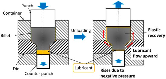
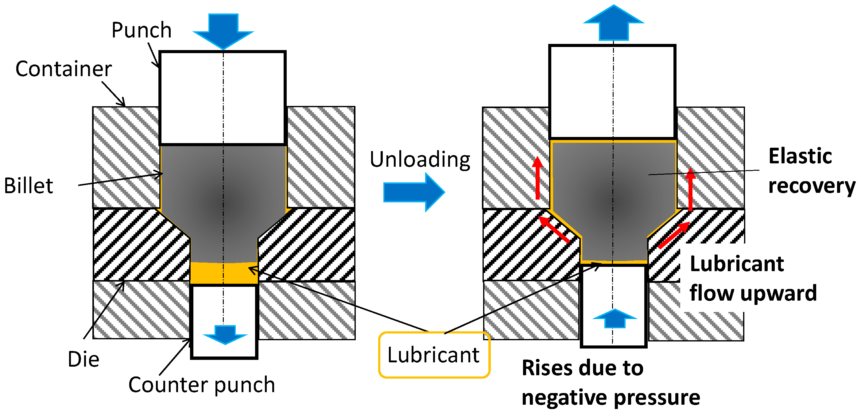
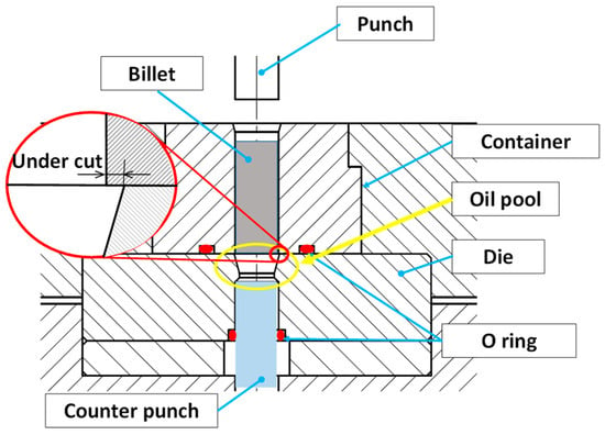
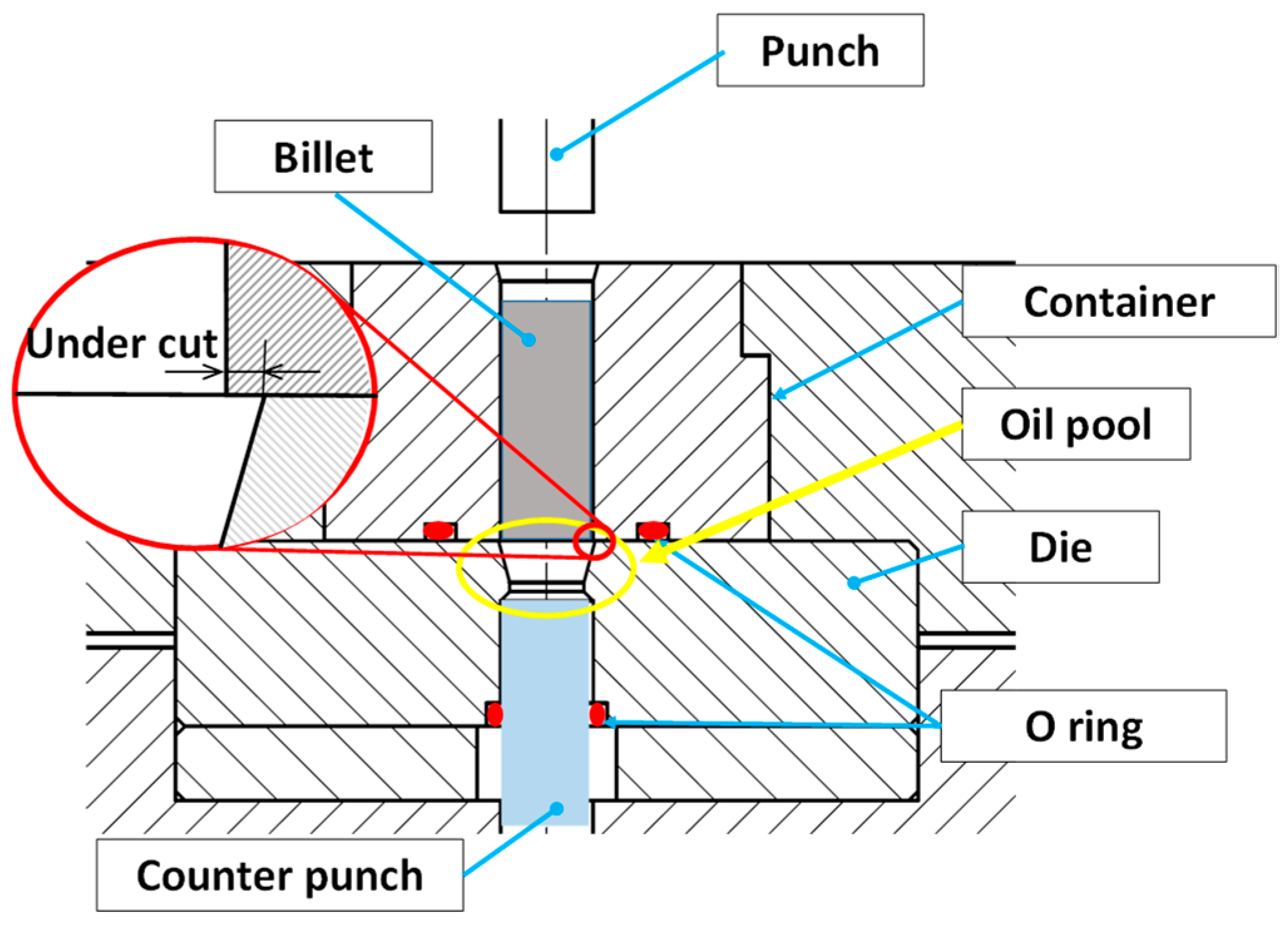
Figure 1 shows the mechanism of continuous lubrication. The billet is pushed in by a punch to perform a conventional forward extrusion. If liquid lubricant is used for a single stroke of processing, the lubricant flows out during the process, causing the oil film between the billet and the die to break. This increases friction, leading to seizing and other issues that result in defects in the billet or die. Therefore, by using a counterpunch to create an oil pool, illustrated on the left side of Figure 1, and then retracting the punch to relieve the load during the forming process—illustrated in the right side of Figure 1—the counterpunch rises due to negative pressure. This creates a gap between the billet and the die, allowing lubricating oil to enter the gap and thereby achieving relubrication. Furthermore, even simply relieving the load can produce a relubrication effect due to the gap formed by elastic recovery, owing to the difference in their Young’s moduli.
Figure 1.
Schematic diagram of continuous lubrication.
2.2. Die Design
To examine the effect of die half-angle, an excess shear deformation term was added to the elementary analysis method [37] that accounts for friction in the container section. The extrusion pressure p was derived using the friction coefficient µ, as shown in the following equation:
where α is the die half-angle, A0 is the initial cross-sectional area, A1 is the cross-sectional area after forming, Y is the yield stress, µ is the die friction coefficient, µc is the container friction coefficient, and l is the contact length of the container section.
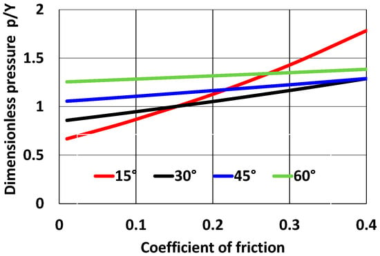
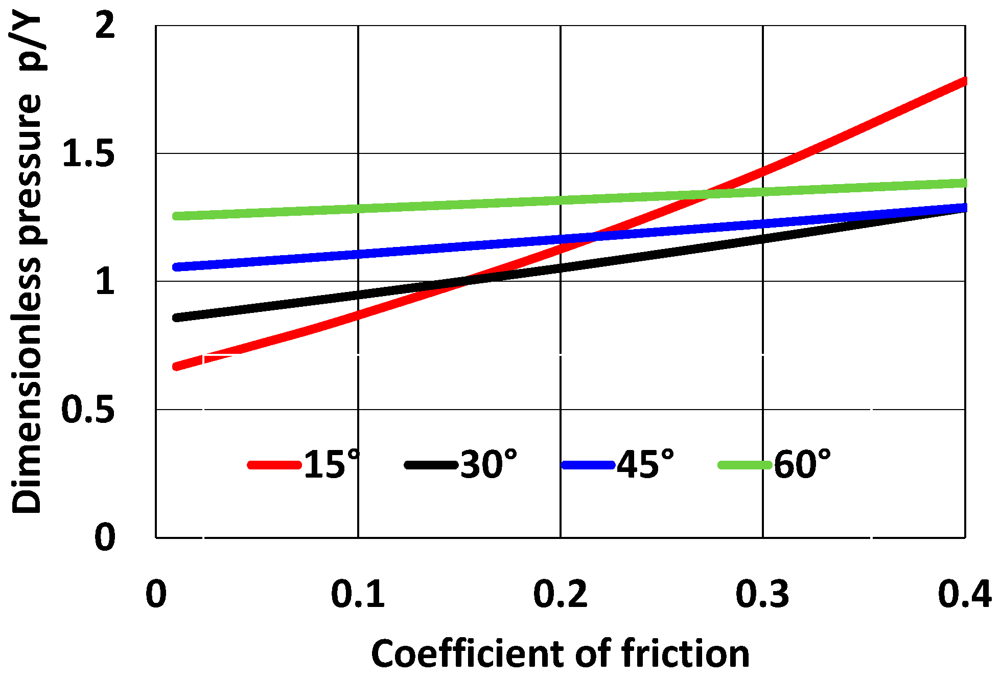
The analysis was performed with an initial diameter of 10 mm and a post-forming diameter of 8 mm (a reduction ratio of 36%), while varying the die friction coefficient µ from 0.01 to 0.4. The residual length of the container section was set to l = 15 mm, and µc was set to 0.03 and 0.1. Figure 2 shows the extrusion pressure normalised by the yield stress Y. Figure 2 shows that the friction coefficient of the container section affects the extrusion pressure. Furthermore, as the die half-angle is reduced, the influence of friction at the die is increased. In order to evaluate the characteristics, a die half-angle of 15° was utilised. As illustrated in Figure 3, the working section of the die is depicted. In an integral die employed for forward extrusion to produce long components, the container and die become a deep hole; consequently, it is not possible to apply a coating inside the hole. This results in stress concentration at the boundary between the die and the container, leading to a reduction in the die’s lifespan. It can thus be concluded that the division of the die facilitates the application of a coating to the interior of the hole. However, if the hole diameters at the die connection points are identical, the material flashes into the gap of the parting line. In order to prevent the occurrence of this flashing, an undercut split die was utilised, with the diameter of the die connection points being made slightly larger. The undercut length was set to 0.5 mm. Furthermore, O-rings were installed at the extrusion die split joint and the bottom of the die, and a counterpunch was used to seal in liquid lubricant. The counterpunch was supported by a spring (spring constant: 0.12 N/mm) to prevent it from coming out.
Figure 2.
Extrusion pressure calculated using the slab method.
Figure 3.
Working section of the extrusion die in proposed continuous lubrication method.
3. Characteristic Evaluation Tests (Single-Step Geometry)
3.1. Experimental Conditions
Table 1 shows the experimental conditions (single step). Liquid lubricant for aluminium was applied to the billet, the container hole area, and the interior of the die. To investigate the effects of oil pool, 0.3 mL and 1 mL of lubricant—volumes equivalent to the oil pool volume—were filled into the die in advance. The billet was then inserted into the container, and the experiment was conducted. For the pulse motion, during unloading, the punch was raised by 1 mm, held for 0.2 s, and then lowered by 2 mm. In order to suppress the temperature rise caused by the generation of heat during the processing stage, it was necessary to set the average speed under load to approximately 5 mm/s. In addition, given the propensity of a higher reduction ratio to enhance the flow of lubricant into the undercut area, the reduction in area was set to 36%. For comparison, lanolin (paste form) was applied only to the billet. Comparisons were made for each of the following factors: presence or absence of sealing, presence or absence of pulsed motion, differences in lubricant volume, and differences in lubricant type. Tests were conducted twice under each condition. The experimental apparatus employed in this study was a 450 kN servo press manufactured by Komatsu.
Table 1.
Experimental conditions (single step).
3.2. Surface Roughness
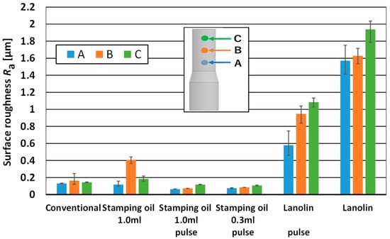
The measurement of three or four points (A–D), as shown in Figures 7 and 13 below, was conducted using a KEYENCE laser microscope (VK-X150), with the objective lenses set to 20× and 50×. Surface characteristics were measured at 20× magnification, and line surface roughness (Ra) perpendicular to the extrusion direction was measured at three points based on data obtained at 50× magnification.
3.3. Results and Discussion
- (a)
- Effect of motion
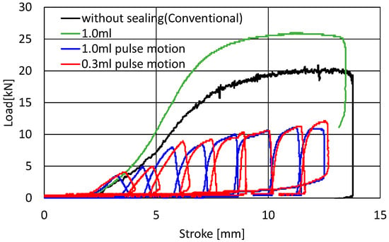
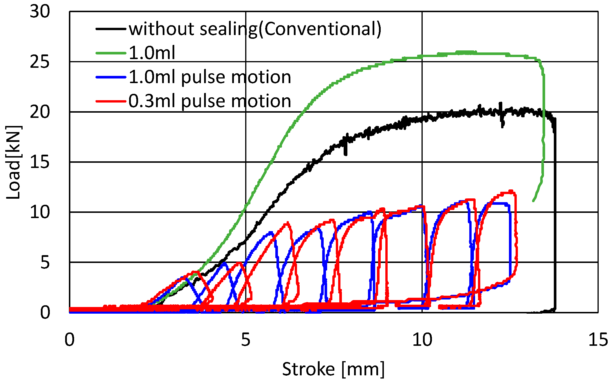
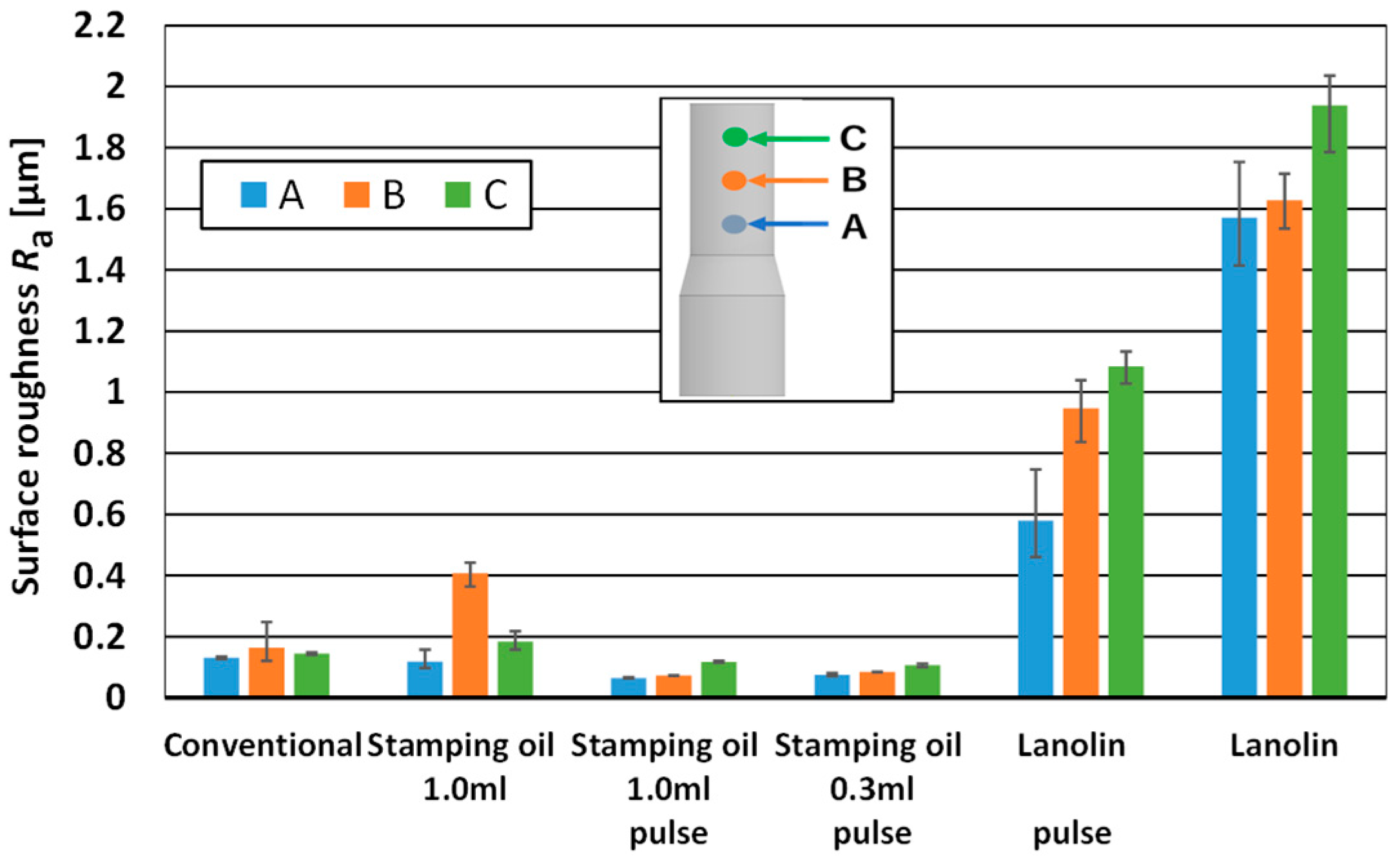
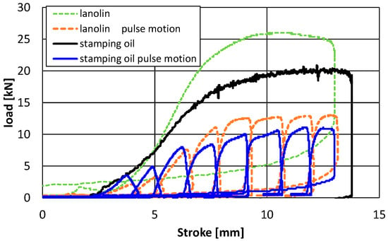
Figure 4 shows the load–stroke diagram (comparison of single-stage pulse motion and lubrication volume), Figure 5 shows the billet appearance, Figure 6 shows the surface characteristics at point A (shown in Figure 7), and Figure 7 shows the surface roughness.
Figure 4.
Load–stroke diagram (comparison of pulse motion and lubrication volume).
Figure 5.
Appearance after forming (single step), (a) conventional, (b) 1.0 mL stamping oil, (c) 1.0 mL stamping oil with pulse motion, (d) 0.3 mL stamping oil with pulse motion, (e) lanolin with pulse motion, (f) lanolin without pulse motion.
Figure 6.
Surface appearance after forming (single step at Point A), (a) conventional, (b) 1.0 mL stamping oil, (c) 1.0 mL stamping oil with pulse motion, (d) 0.3 mL stamping oil with pulse motion, (e) lanolin with pulse motion, (f) lanolin without pulse motion.
Figure 7.
Surface roughness after forming (single step).
- (i)
- Sealing: In comparison with instances that did not involve sealing or pulse motion, the load exhibited an approximate augmentation of 5 kN when 1.0 mL of stamping oil was utilised without pulse motion. It is hypothesised that this was due to an increase in processing load caused by the force acting on the tip of the extrusion section. This is believed to have resulted from the sliding resistance of the O-ring and counterpunch, which caused greater widening into the undercut area of the deformed section. Conversely, surface roughness Ra exhibited a decline from approximately 0.13 μm to approximately 0.10 μm. Moreover, a comparison of the billet appearances displayed in Figure 5a,b with the surface appearances illustrated in Figure 6a,b reveals that the sealed billet demonstrated a marginally elevated gloss level and a diminished presence of shallow streaks in the extrusion direction. This phenomenon can be attributed to the enhanced lubrication effect of the increased amount of lubricant, which prevented the rupture of the oil film.
- (ii)
- Pulsation: A comparison of conditions with and without pulse motion revealed that the application of vibration resulted in a reduction of the load, which had previously necessitated 20 kN or more, to approximately 10 kN. Concurrently, despite the substantial reduction in load, the decrease in surface roughness was negligible. It has been demonstrated that in the absence of pulsation, the oil film becomes thin, causing an increase in friction and an increase in the load due to the flowing into the undercut. Conversely, with pulse motion, the oil film becomes thicker, reducing friction, and allowing the component to be pushed out without flowing into undercut.
- (iii)
- Lubricant volume: As the lubricant volume was observed to be 0.3 mL, it was noted that a load increase of approximately 2 kN was evident during the eighth unloading cycle. It is hypothesised that the lubricant volume was insufficient, resulting in the rupture of the oil film, as this phenomenon was not observed in the 1.0 mL sample. Nonetheless, an absence of correlation was identified between surface roughness and the quantity of lubricant utilised. Consequently, even with 0.3 mL, the minimum oil film necessary for forming was maintained.
- (b)
- Comparison of liquid and paste-type lubricants
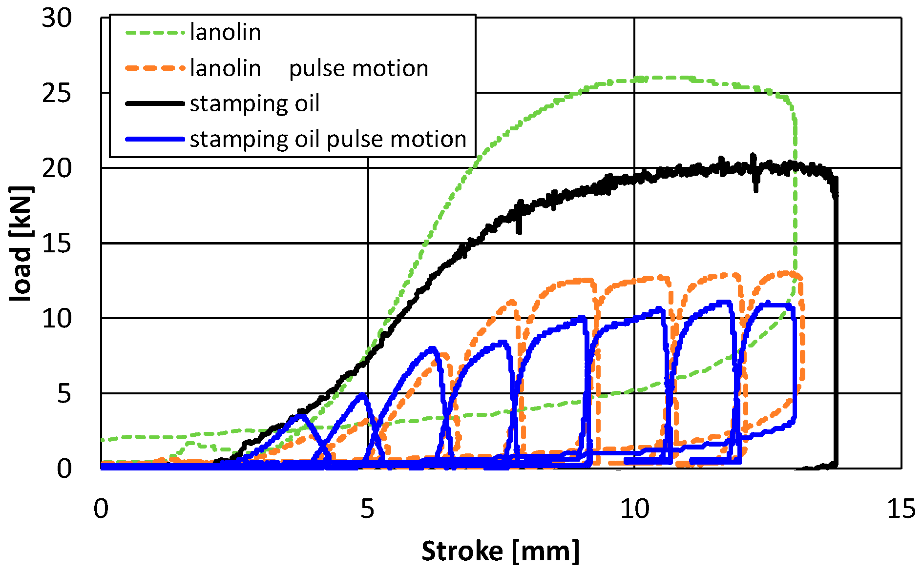
Figure 8 shows the load–stroke diagram (comparison between liquid lubricant (1.0 mL) and paste-type lubricant).
Figure 8.
Load–stroke diagram (comparison between liquid lubricant and paste-type lubricant).
- (i)
- Type of lubricant: In the absence of pulse motion during the application of lanolin, the load exhibited an approximate augmentation of 5 kN in comparison with the utilisation of stamping oil without pulse motion. This phenomenon is hypothesised to be attributable to the higher coefficient of friction exhibited by lanolin in comparison to stamping oil. Additionally, the surface roughness of the material exhibited an increase from an initial Ra value of approximately 0.8 μm to approximately 1.6 μm. A comparison of the appearance of the billets in Figure 5b,f demonstrates that the gloss level was significantly lower in the lanolin group than in the stamping oil group. In addition, surface observations revealed the presence of scratches, which suggests that the oil film may undergo a breakdown without pulse motion.
- (ii)
- The application of pulse motion to lanolin resulted in a substantial decrease in load. In addition, gloss was observed in the billets that had been subjected to pulse motion, in comparison to the condition that did not exhibit vibration. This finding indicates that, even in the presence of lanolin, a relubrication effect analogous to that observed with oil-based materials can be attained. However, as demonstrated in Figure 5e and Figure 6e, the surface roughness Ra remains high at approximately 1 μm. This phenomenon is attributed to the roughness of the material’s free surface, which is caused by the high viscosity of lanolin. This results in a thicker oil film. The load for the test using lanolin with pulse motion was approximately 3 kN higher than that for the test using stamping oil with vibration. This phenomenon can be attributed to the high coefficient of friction exhibited by lanolin, as previously discussed in the section addressing tests conducted without pulse motion.
4. Experimental Conditions (Two-Step Geometry)
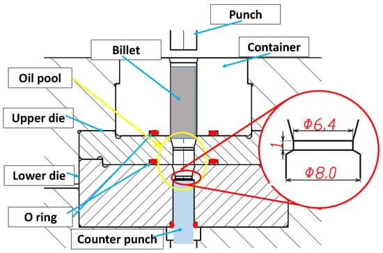
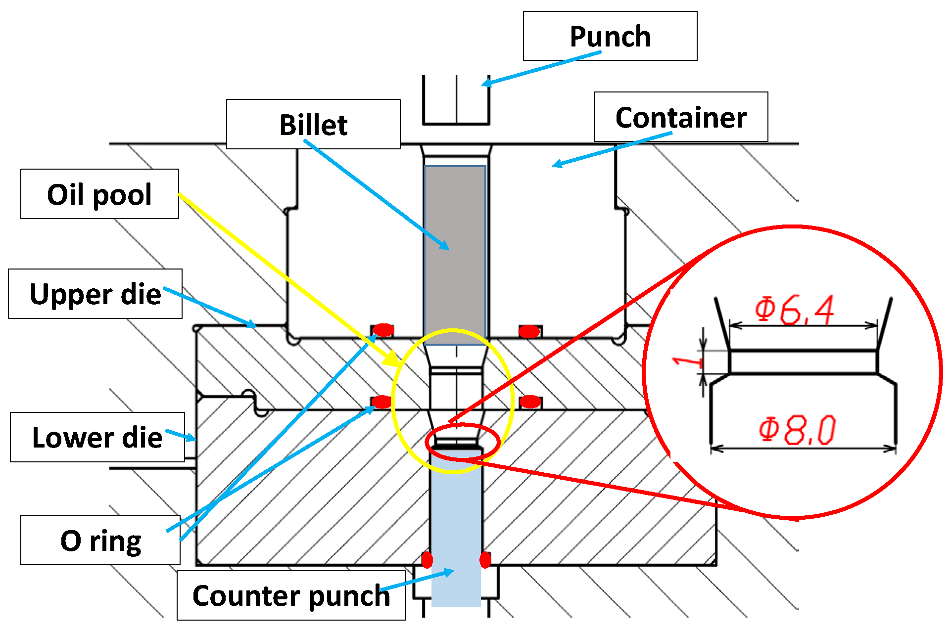
In light of the findings from the preceding chapter, which demonstrated that the application of a marginally greater quantity of lubricant than the oil pool, in conjunction with pulse motion, can markedly diminish the load, the proposed method was employed in the formation of a two-step geometry. The experimental conditions are outlined in Table 2. The material was changed to A5056. The quantity of lubricant was set to 2.0 mL, which is slightly more than double the 0.85 mL used for the oil pool method. In the two-stage test, billets of varying diameters were utilised to investigate the effect of the clearance between the die and the billet on relubrication behaviour. Furthermore, the die half-angle of the upper die was modified. As illustrated in Figure 9, the working section of a two-step extrusion die is demonstrated. The test was conducted three times under each condition.
Table 2.
Experimental conditions (two-step).
Figure 9.
Working section of the extrusion die (two-step).
5. Experimental Results and Discussion
5.1. Effect of Clearance
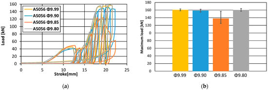
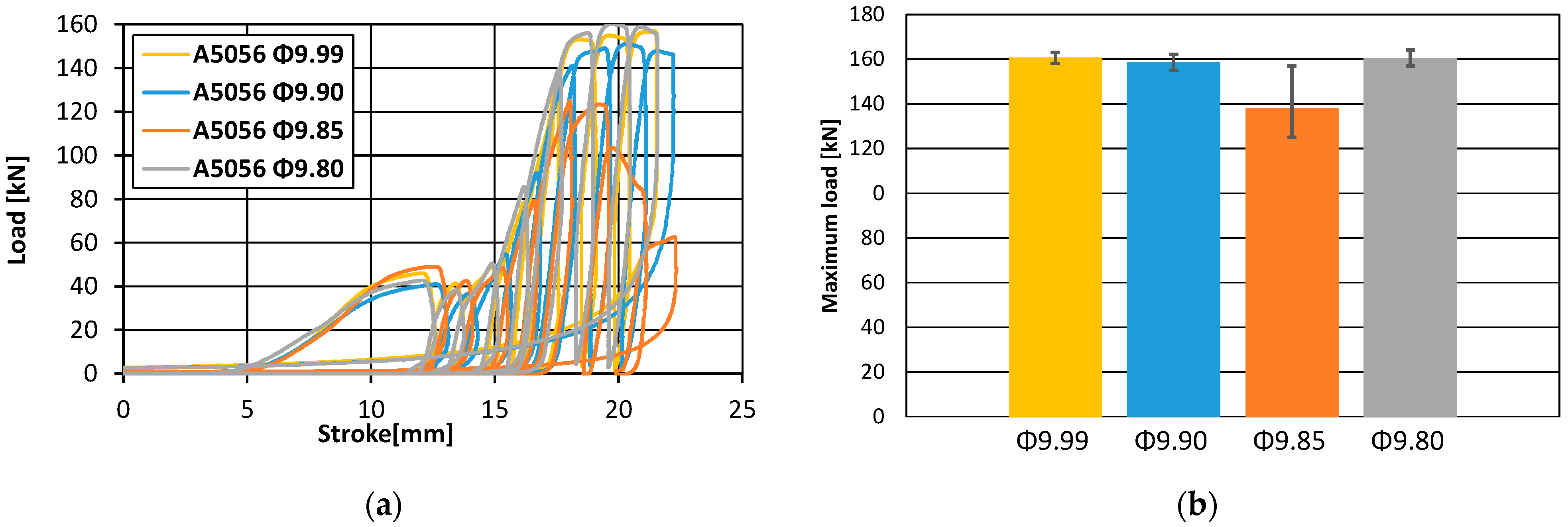
Figure 10a shows the experimental load–stroke diagram, and Figure 10b shows the maximum load. As demonstrated in Figure 10b, the maximum load exhibits a decrease as the clearance increases up to a maximum of Φ9.85. It is hypothesised that the presence of a clearance between the billet and the container facilitates the entry of lubricant into the gap during the insertion of the billet. This lubricant is then stored within the gap until the billet’s outer diameter expands within the container section. This process enables the lubricant to enter the upper portion during the pulsed motion, thereby achieving a greater relubrication effect. Furthermore, it is hypothesised that the accumulation of lubricant in the clearance reduces friction in the container section.
Figure 10.
(a) Load–stroke diagram (two-step). (b) Maximum load.
As shown in Figure 10a, the load during pulse motions from the sixth cycle onward decreased significantly only for the Φ9.85 case. The container section, which had the largest contact area during forming and was most affected by friction, achieved a favourable lubrication state, leading to a reduction in load. However, the load increased for the Φ9.80 case, which had a larger clearance and could store more lubricant. For Φ9.80, it was confirmed that lubricant leaked from the upper part of the container during forming. This suggests that when a large clearance allows for the accumulation of a large amount of lubricant, as forming progresses and the volume of the clearance decreases, the unused lubricant leaks out from the top of the container. It is believed that this leakage of large amounts of lubricant leads to a shortage of lubricant within the die, making it difficult to achieve the desired relubrication effect.
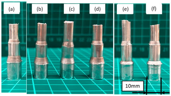
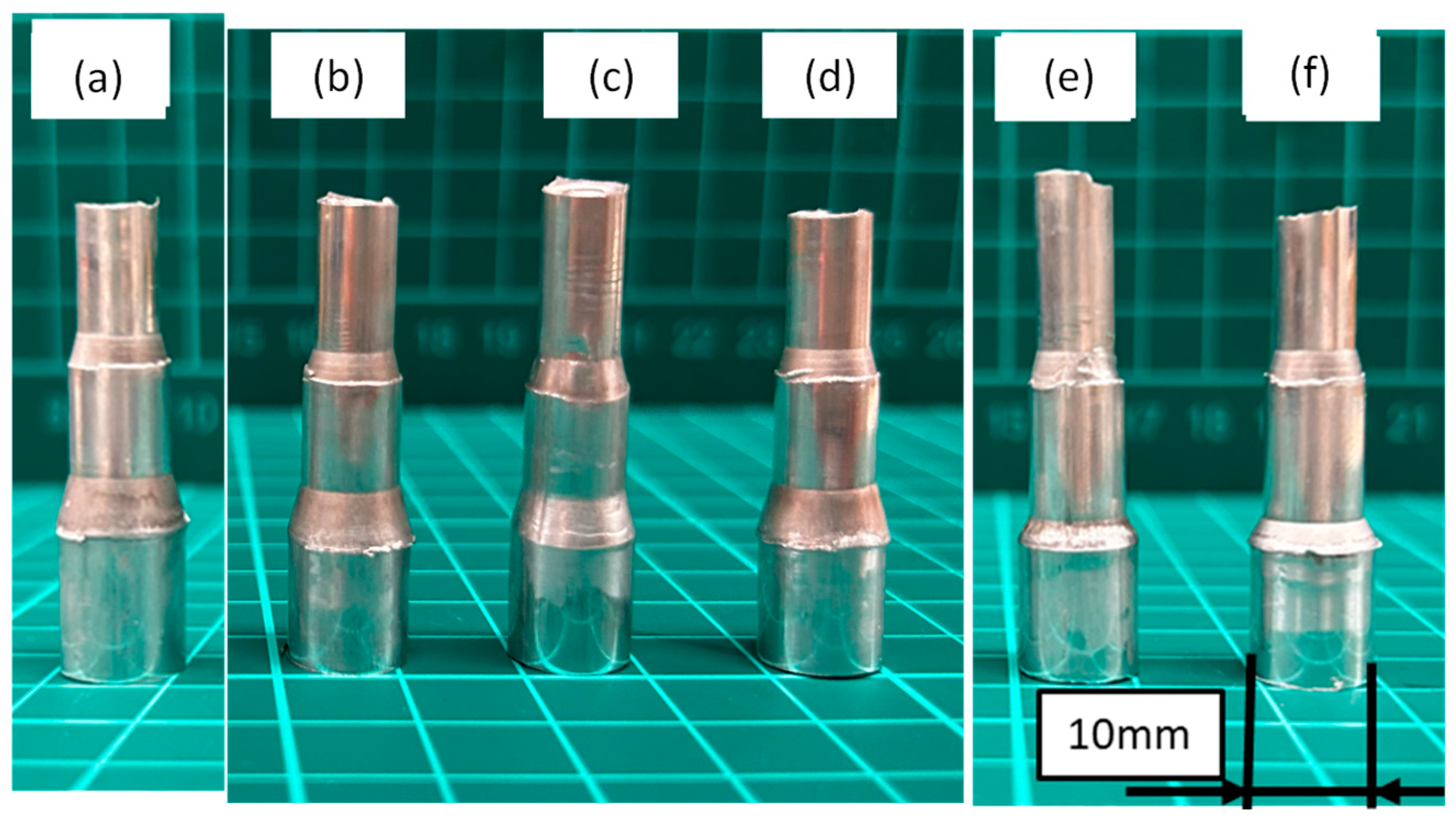
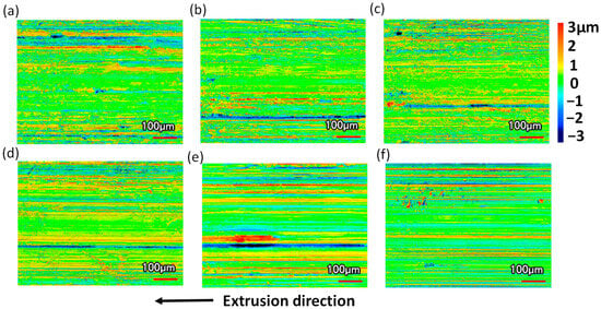
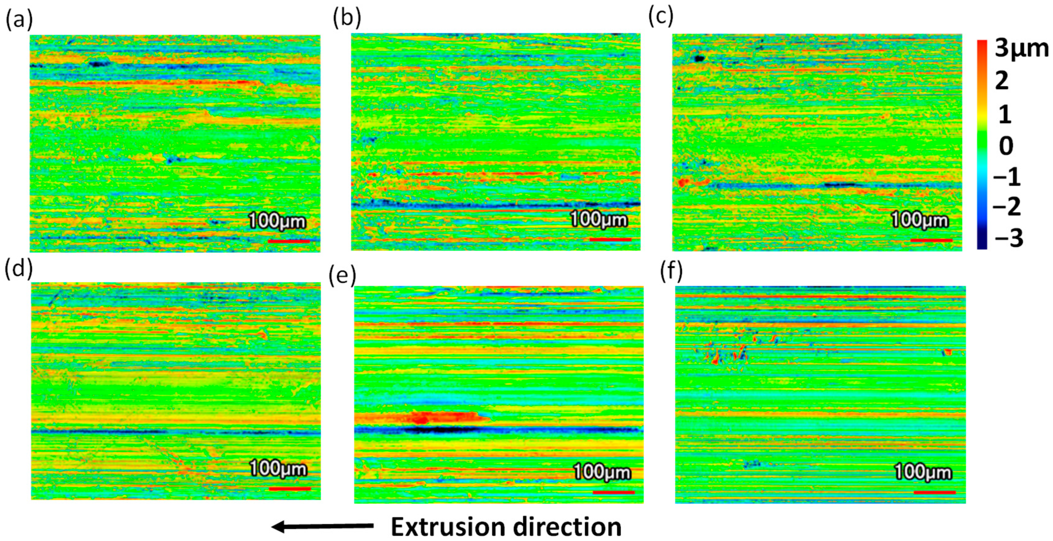
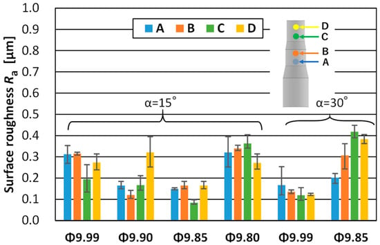
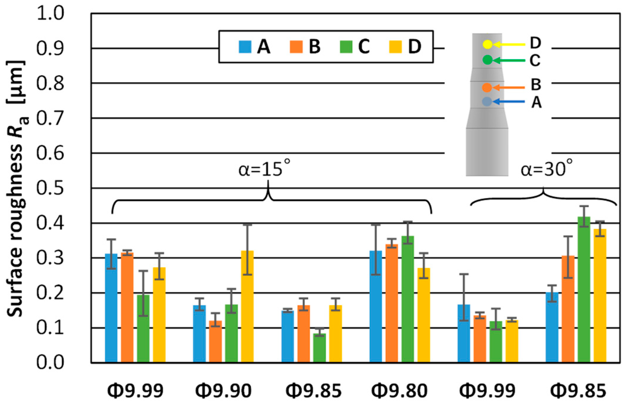
Figure 11 shows the billet appearance, Figure 12 shows the surface characteristics at point A (shown in Figure 13), and Figure 13 shows the surface roughness. These figures include results for α = 30°.
Figure 11.
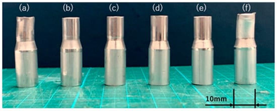
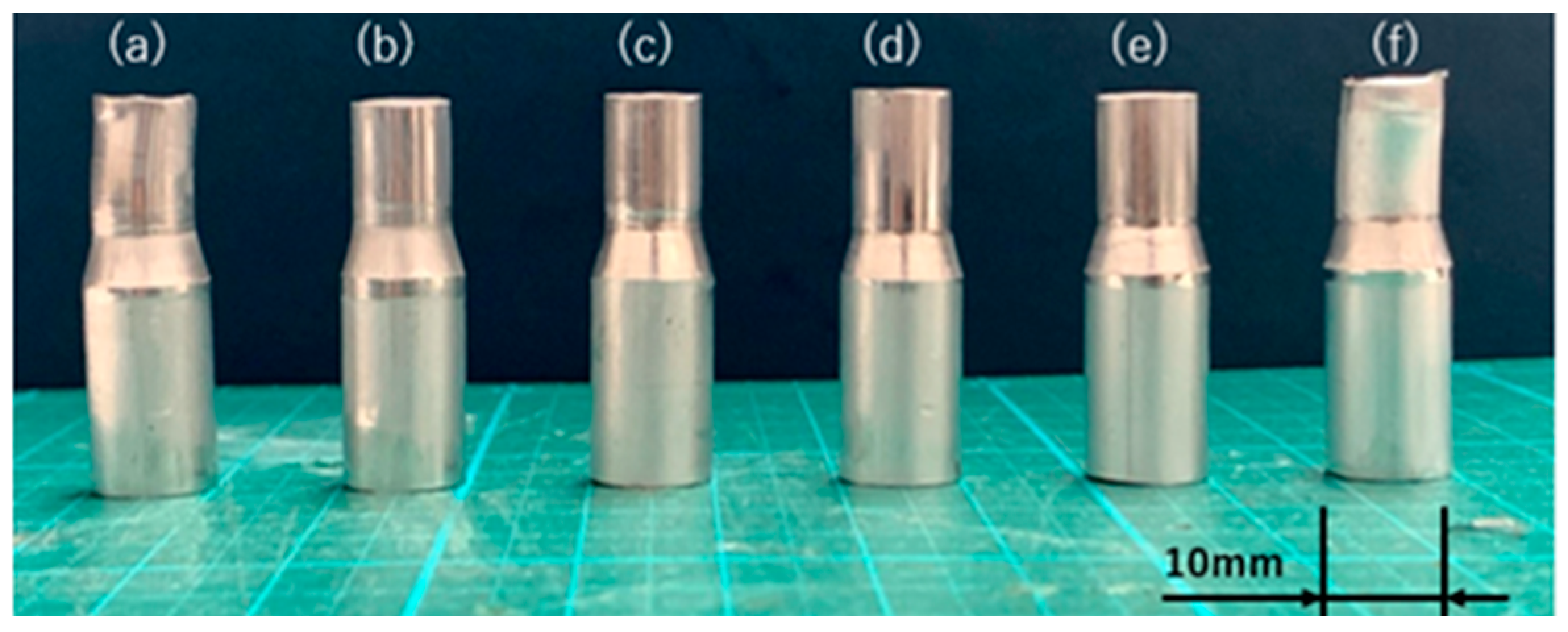
Appearance after forming (two-step), (a) die half-angle α = 15°, Φ9.99 mm, (b) α = 15°, Φ9.90 mm, (c) α = 15°, Φ9.85 mm, (d) α = 15°, Φ9.80 mm, (e) α = 30°, Φ9.99 mm, (f) α = 30°, Φ9.85 mm.
Figure 12.
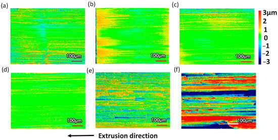
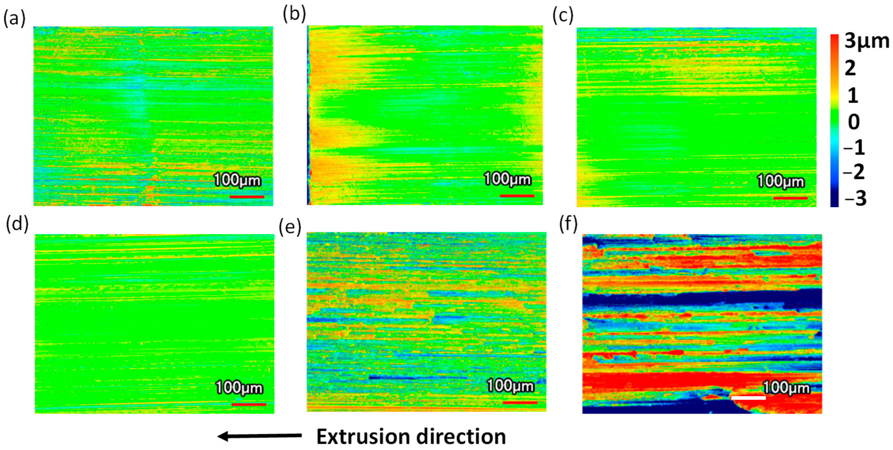
Surface appearance after forming (two-step at Point A) (a) die half-angle α = 15°, Φ9.99 mm; (b) α = 15°, Φ9.90 mm; (c) α = 15°, Φ9.85 mm; (d) α = 15°, Φ9.80 mm; (e) α = 30°, Φ9.99 mm; (f) α = 30°, Φ9.85 mm.
Figure 13.
Surface roughness after forming (two-step).
As shown in Figure 11, it can be seen that all billets had a glossy surface. Furthermore, for the Φ9.85 billet, it can be seen that the flow into the undercut area at the first-stage die was minimal. Although no significant differences due to clearance were observed in the surface appearance shown in Figure 12, scratches of approximately 1 µm were observed compared to single-stage forming (Figure 6). This is thought to be due to a break in the oil film caused by lubricant leakage, resulting in increased surface roughness, as shown in Figure 13.
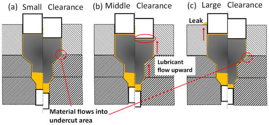
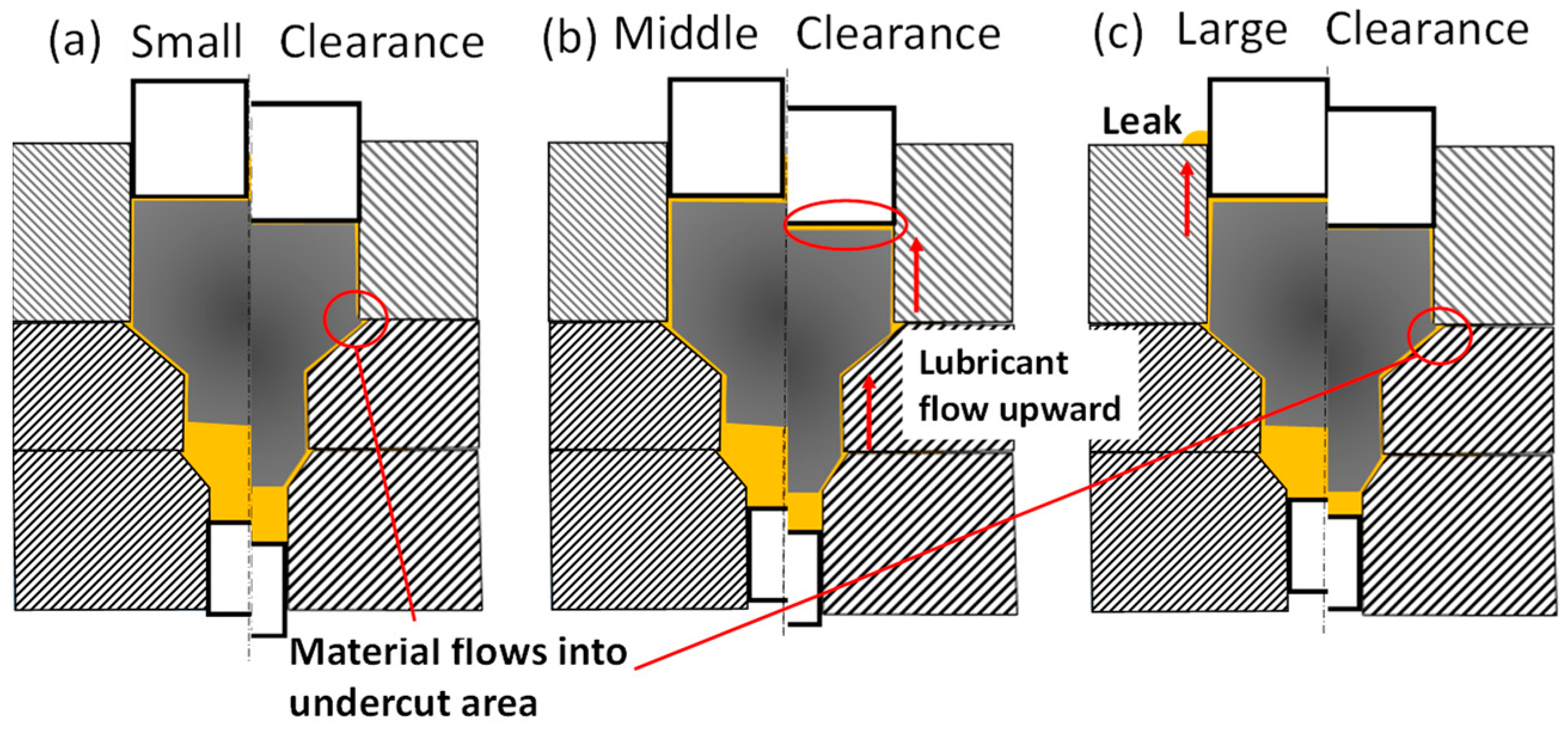
In light of these results, the lubrication model depicted in Figure 14 is hereby proposed. If the clearance is too small, sufficient lubricant cannot be retained between the punch and the billet during the first-step forming, as shown in Figure 14a. Furthermore, when the clearance is large, as in the case of Φ9.80, the sealing effect due to billet deformation cannot be achieved. As illustrated in the left figure of Figure 14c, lubricant leaks out at the early in the process, making it impossible to retain a sufficient quantity of lubricant. This phenomenon results in enhanced material influx into the undercut region, impeding the re-lubrication process of the container area during unloading. With an appropriate clearance, as illustrated in Figure 14b, the relubrication effect from the lower oil pool entering the container during unloading leads to a significant reduction in forming load after a stroke of 20 mm, as shown by the Φ9.85 condition in Figure 10a.
Figure 14.
Lubrication mechanism in different clearance.
5.2. Comparison of Die Half-Angle
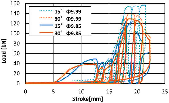
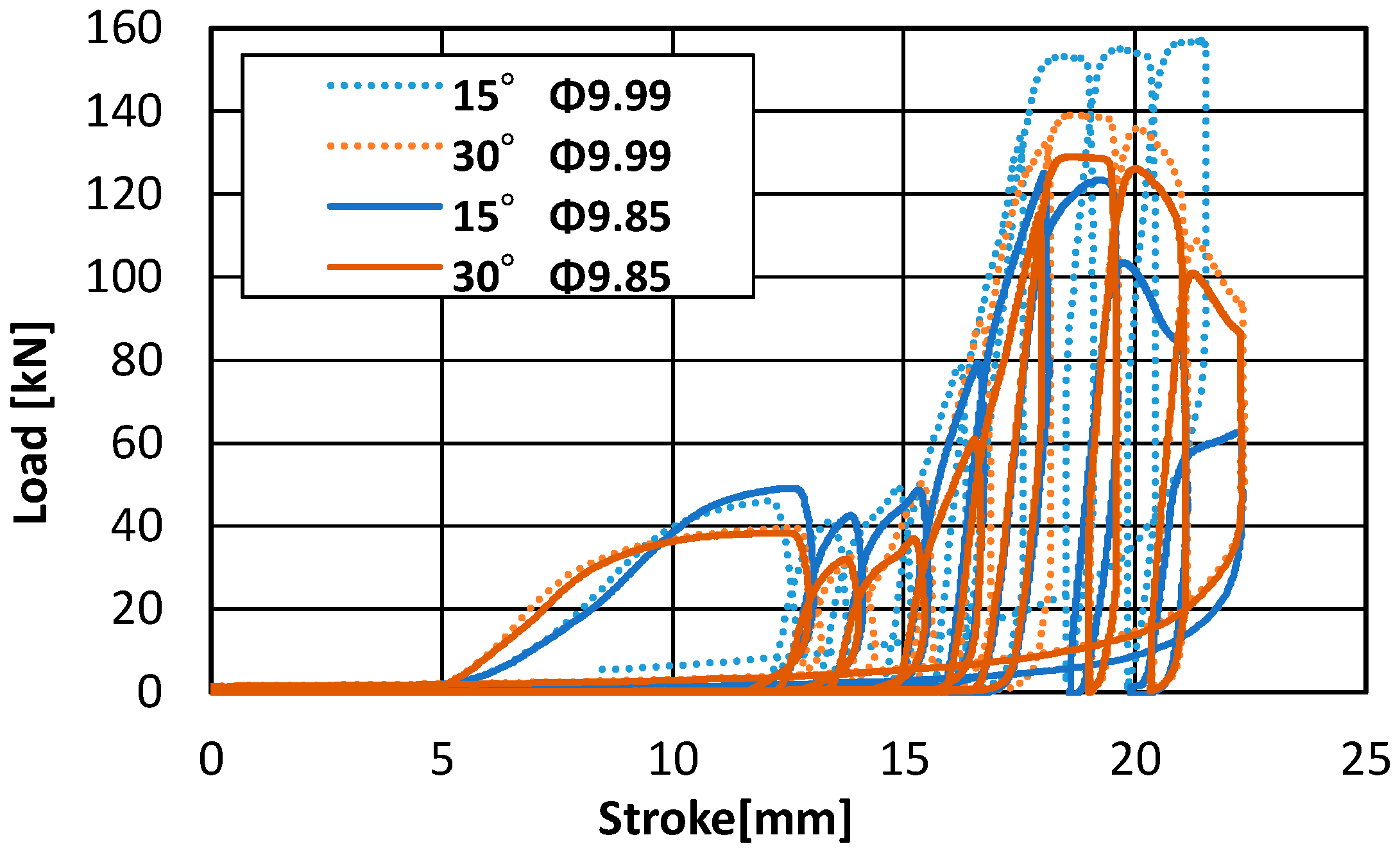
Figure 15 shows that the load in the first stage was found to be lower for α = 30°. Table 3 shows the maximum load and standard deviation, along with the results from Section 5.1. This indicates that, as shown in Figure 2, when the coefficient of friction µ was 0.15 or less, the load was lower for a α = 30° than for 15° at the same coefficient of friction, demonstrating that friction was lower at α = 30°. In the second step of forming, where a stroke of 15 mm or more was employed, the maximum load for α = 30° was reduced by approximately 20 kN. As demonstrated in Figure 15, the provision of clearance resulted in a reduction of the maximum load for both α = 15° and α = 30°. As shown in Table 3, α = 30° demonstrates reduced variations in maximum load.
Figure 15.
Load–stroke diagram (comparison of die half-angle and clearance between the container and billet).
Table 3.
Maximum load and standard deviation.
5.3. FEM Simulation
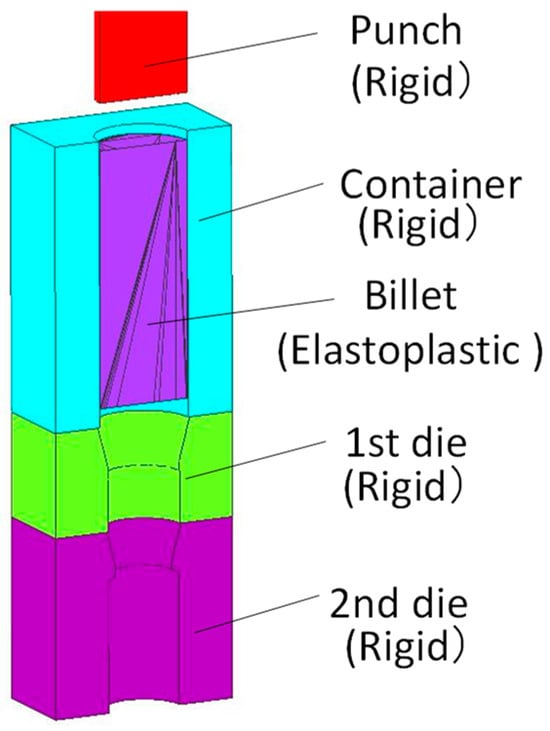
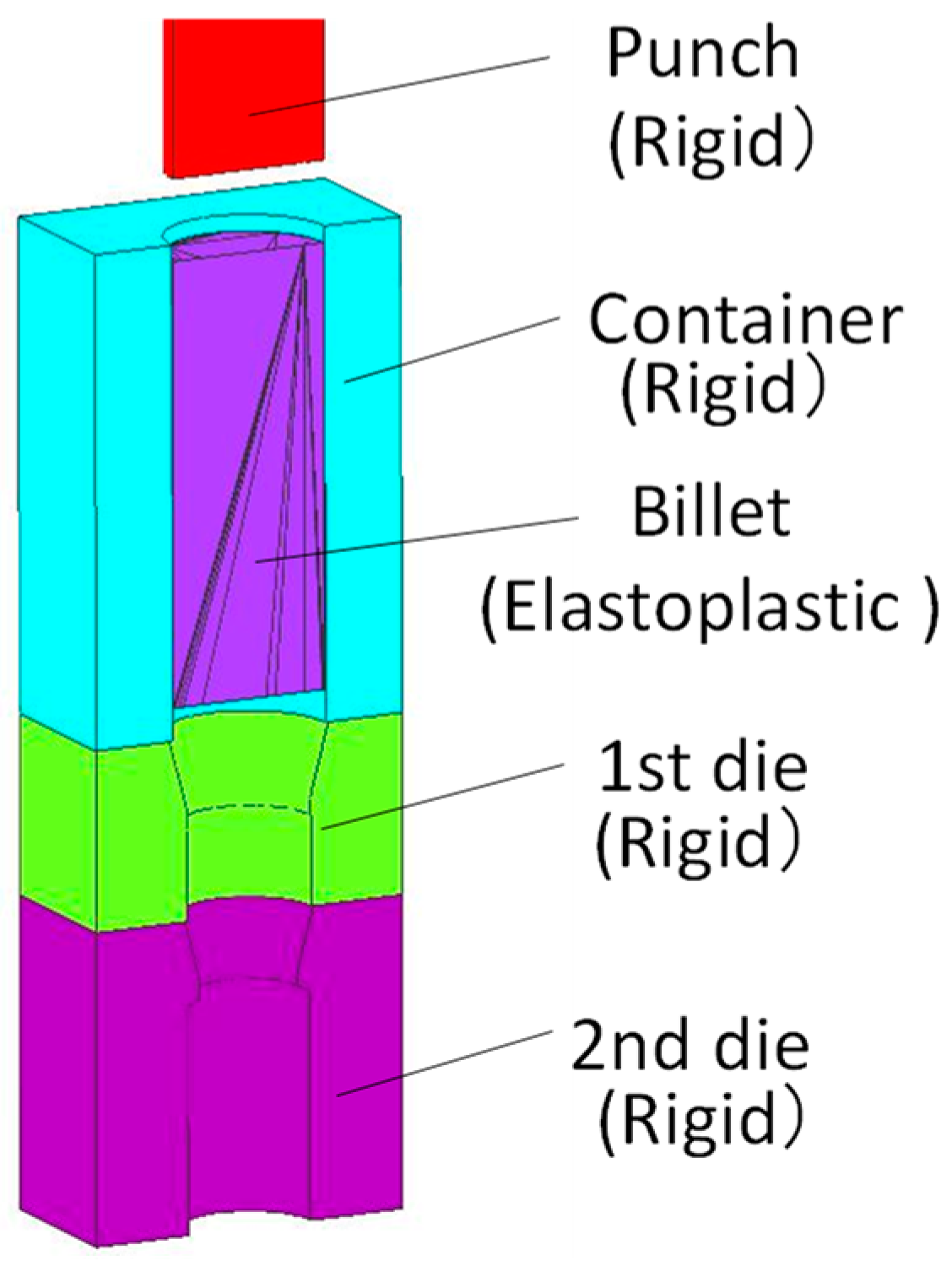
To investigate changes in the coefficient of friction during processing, a finite element method (FEM) simulation was performed using an axisymmetric model in Simufact.forming 2024.3. The application module was set to “cold forming,” and the process type within the module was set to “extrusion”. The residual convergence ratio was set to 0.001 as the convergence criterion. Contact detection was performed using the node-to-segment method, with a tolerance of 1/20 of the minimum element length and a bias value of 0.9. The separation was determined by stress and set at 30 MPa. The coupled Coulomb–shear friction model was employed, with the switching value set to shear friction factor m = 1. This ensured that the frictional force was equal to the material’s shear yield stress. The forming conditions were the same as those in Table 2; however, no pulsed motion was applied, and forming was performed in a single stroke. The speed was set to 2 mm/s based on the forming time when pulsed motion was applied. The billet was modelled as an elastoplastic body, and the A5056 stress–strain relationship, which accounts for temperature and strain rate dependencies, built into the software was utilised. The billet dimensions were set to a diameter of 9.90 mm and a length of 27 mm. The tool was modelled as a rigid body, and the friction coefficient was set to the same value for the container, die, and punch. The analysis was performed with μ varying between 0.05 and 0.13. Element meshing was performed using the Advancing Front Quad method (Quad Type 10), with an element size of 0.2 mm. Elements that had been deformed during the forming process were remeshed once they had reached a strain of 0.4. The initial temperature was set to 20 °C; the heat transfer coefficients between the tool and the test specimen were set to 20,000 (W/(m2·K)), and heat dissipation to the atmosphere was set to 50 (W/(m2·K)). The tool temperature was held constant at 20 °C. Figure 16 shows the analysis model.
Figure 16.
Finite element analysis model for elastic–plastic deformation of two-step forward extrusion.
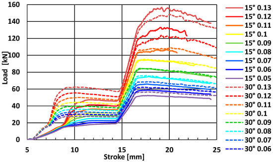
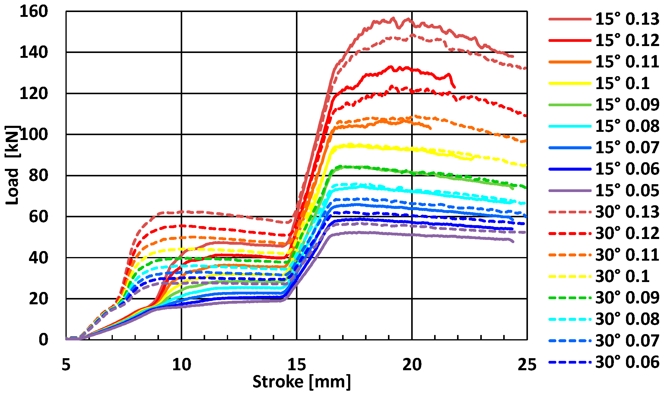
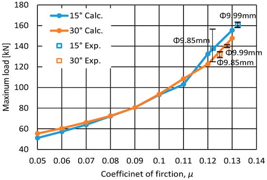
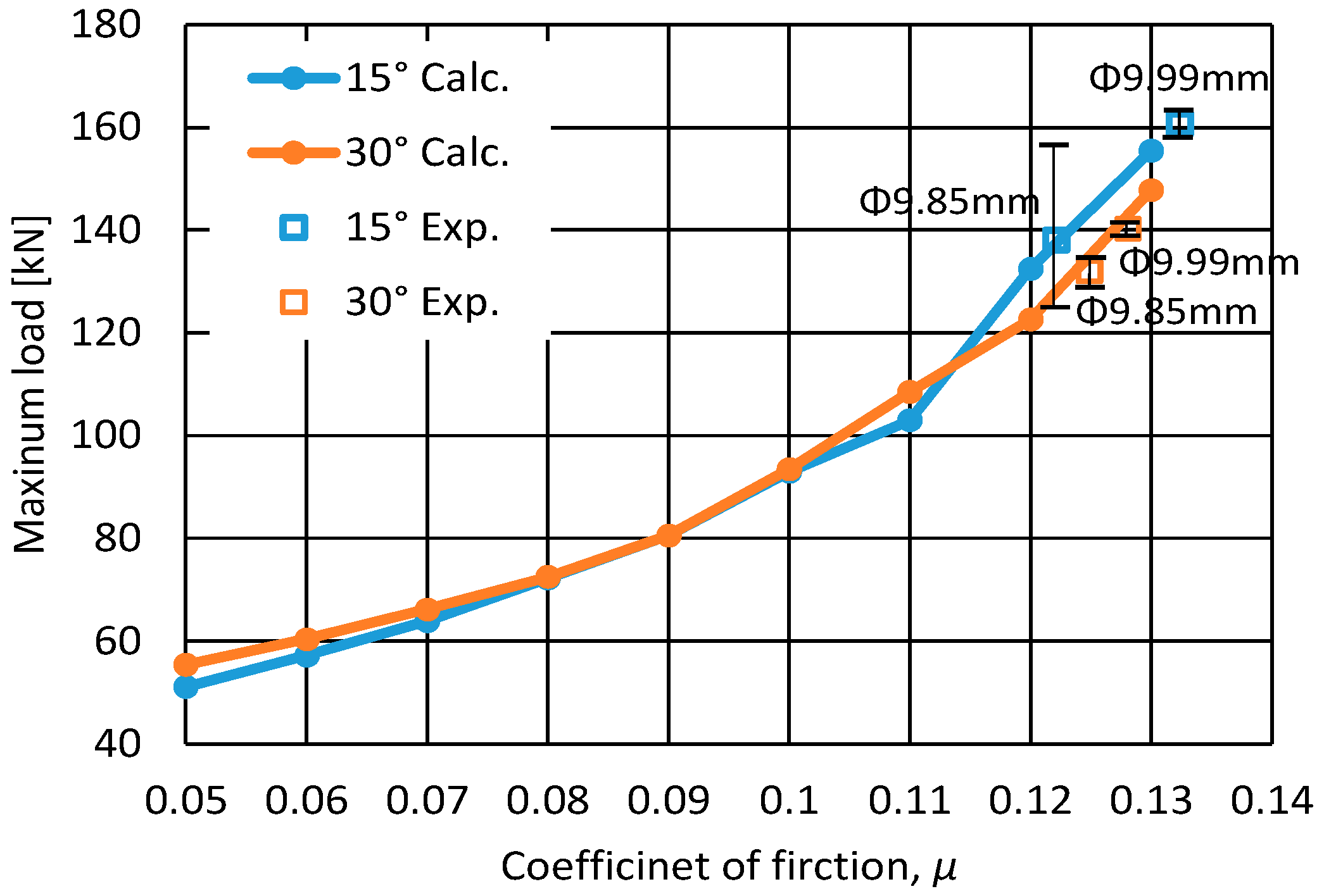
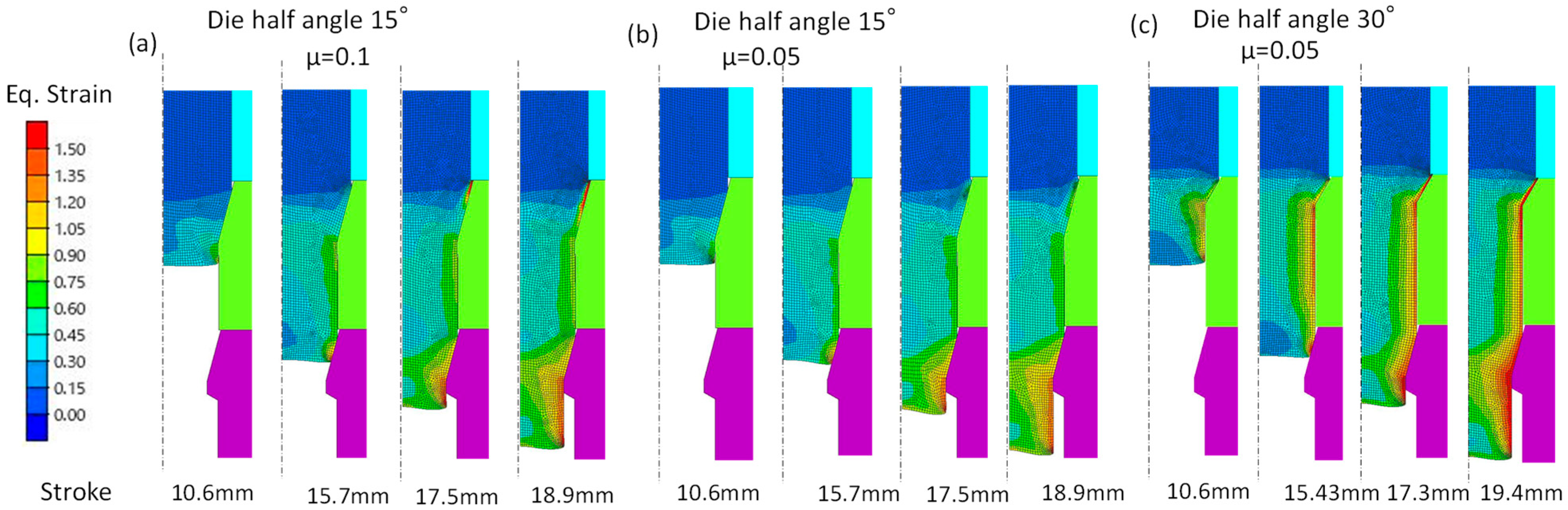
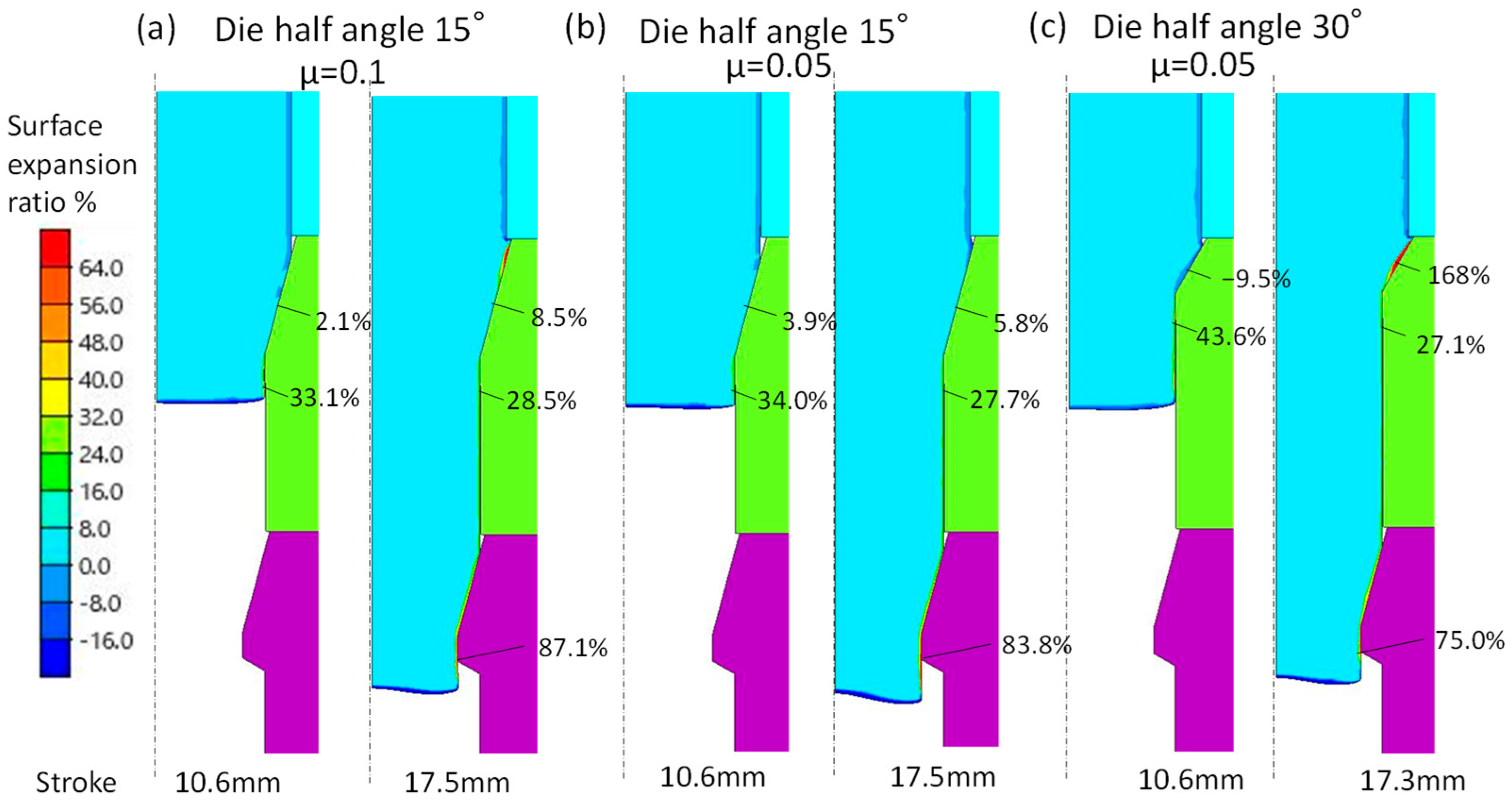
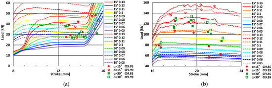
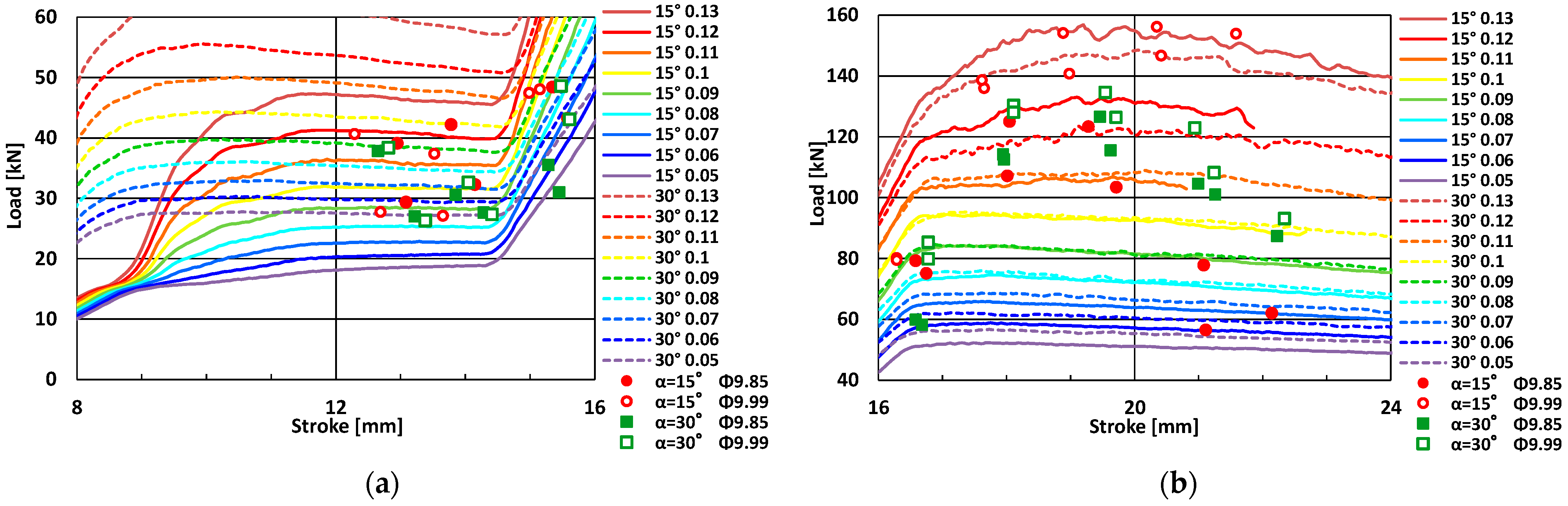
Figure 17 shows the load–stroke diagram obtained from the analysis. Figure 18 shows the relationship between the coefficient of friction and the maximum analytical load. The maximum load shown here is the average value for a stroke of 19.5–20.5 mm. The experimental load values are also shown alongside the positions of the coefficients of friction, which are obtained by quadratic interpolation of the analytical results from the maximum experimental load values. Figure 19 and Figure 20 show the equivalent strain distribution and the surface expansion ratio, respectively. Figure 20 also indicates the surface expansion ratio values at the midpoint of the first-stage taper section, at the exit of the bearing section, and at the exit of the second-stage bearing section.
Figure 17.
Load–stroke diagram (analysis results).
Figure 18.
Relationship between the coefficient of friction and the maximum calculated load (experimental values are displayed at the interpolated points).
Figure 19.
Equivalent strain distribution. (a) Die half-angle α = 15°, coefficient of friction μ = 0.1; (b) α = 15°, μ = 0.05; (c) α = 30°, μ = 0.05.
Figure 20.
Surface expansion ratio distribution. (a) Die half-angle α = 15°, coefficient of friction μ = 0.1; (b) α = 15°, μ = 0.05; (c) α = 30°, μ = 0.05.
Figure 17 shows that, for the same coefficient of friction, the load in the first step was higher for the die with α = 30°, while the difference became smaller from the second step onward. This result reflects the greater influence of friction in the container section compared to that in the die. As shown in Figure 18, the rate of increase in load rose significantly when the coefficient of friction exceeded 0.1. Furthermore, the change in maximum load observed in the experiment at α = 15° and Φ = 9.85 corresponds to a change in the coefficient of friction of approximately 0.122 ± 0.005. From Figure 19a, it can be seen that with the die with α = 15° and a friction coefficient µ = 0.1, workpiece (billet) flowed into the undercut of the first stage during forming of the second stage. By a stroke of 18.8 mm, the undercut was almost filled, and the equivalent strain increased. Furthermore, as shown in Figure 19b, the cavity was not filled at µ = 0.05. Additionally, as shown in Figure 19c, for the die with α = 30°, the workpiece flow into the undercut and the surface strain in the first stage were greater than those at α = 15°. Figure 20 shows that, for the die with α = 15°, the surface expansion ratio for the first stage was slightly higher when the coefficient of friction was lower. This phenomenon can be attributed to the fact that a reduction in friction facilitates flow in the extrusion direction. Furthermore, at 30°, the surface expansion in the tapered section took on a negative value. It can be seen that the surface expansion ratio decreased as the deformation in the first stage reached a steady state.
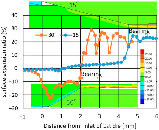
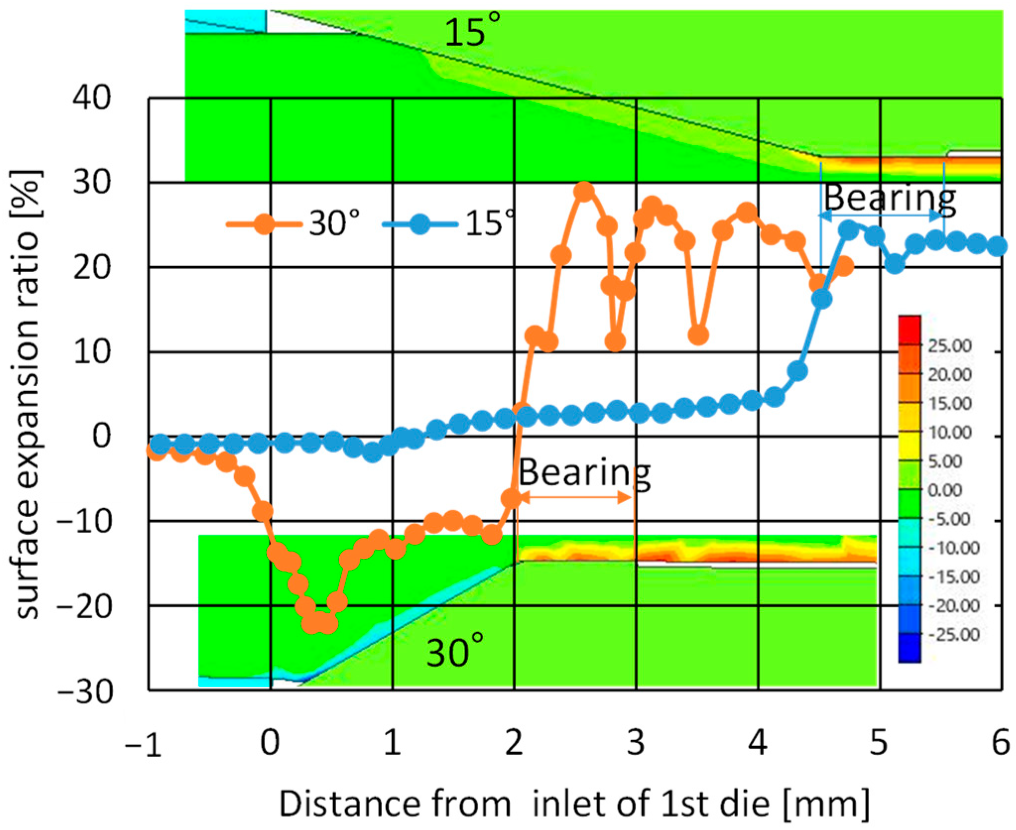
The load–stroke diagram in Figure 21 was employed as a calibration diagram, and the coefficient of friction was calculated using a nomogram. Despite the fact that the friction conditions undergo alteration during the process of forming, this does not precisely simulate the actual formation process. Nevertheless, the changes in load during formation were interpreted as changes in friction conditions in order to derive the coefficient of friction. The coefficient of friction during the first step, with α = 15°, was μ = 0.12 during forming; it decreased to approximately 0.1 at the start of reloading and increased again to approximately 0.12 as forming continued. It is evident from the data that, with an angle of 30°, the coefficient of friction μ was initially at a value of 0.09. This value then decreased to approximately 0.05 at the commencement of the reloading process, subsequently increasing again to approximately 0.08 as the forming process continued. When using relubrication, α = 30° resulted in a shorter sliding distance within the die compared to α = 15°, thereby helping to suppress an increase in friction. Figure 22 shows the change in surface expansion ratio in the extrusion direction at a stroke of 14 mm. The surface expansion ratio increased monotonically in the taper section when α = 15°. In the case of α = 30°, the surface expansion ratio exhibits a decline in the undercut region, reaching a negative value. Thereafter, a sharp increase is observed in the contact area of the tapered section, followed by a gradual rise. The observed fluctuation at α = 30° is hypothesised to be attributable to the effect of remeshing. Additionally, while it has been hypothesised that the negative surface expansion ratio in the undercut region, as illustrated in Figure 20c, may play a role in the trapping of lubricant, although this remains a subject of speculation.
Figure 21.
Analytical and experimental loads. (a) First step forming in two-step geometry, (b) second step forming in two-step geometry.
Figure 22.
Change in surface expansion ratio in the extrusion direction at a stroke of 14 mm. Coefficient of friction μ = 0.05.
During the second step forming, the coefficient of friction for both cases was approximately μ = 0.12; for Φ9.99 at α = 15°, the change in the coefficient of friction due to unloading was small, remaining at around 0.13. For Φ9.85 at α = 15°, μ decreased from 0.12 to 0.07 as forming progressed. Additionally, at α = 30°, the coefficient of friction exhibited a decrease from μ = 0.12 to 0.1.
The validity of the friction coefficients obtained from the analysis was examined based on the results of previous studies. It is evident that these values are lower than the friction coefficient of approximately μ = 0.25 that was reported by Lazzarotto et al. [3]. This phenomenon is attributable to the incorporation of an oiliness agent. The reduction effect due to pulsation caused the coefficient of friction µ to vary within the range of 0.12 to 0.05. Maeno et al. [15] reported that during upsetting, the coefficient of friction decreased to approximately 0.05 during unloading in pulse motion, and then increased to 0.1 upon reloading. This cycle repeated, and the amount of friction reduction gradually decreased. A similar effect was observed in forward extrusion. During the forward extrusion process, lubricant was drawn from the container section into the taper section. As the process continued, the lubricant seeped from the die into the oil pool located at the upper extremity of the counterpunch. Matsumoto et al. [27] conducted direct observations of the taper section during the forging of 1100 aluminium (with the observation position at the centre of the taper section in the longitudinal direction). In a separate study, Yanagida et al. [38] measured oil film thicknesses of 20–40 µm during fluorescent observations of flat drawing with a 15% reduction in area. They observed average oil film thicknesses of approximately 30 µm in the taper section and 0.5 µm in the bearing section at an average contact pressure of 60 MPa. Despite the absence of specification regarding contact pressure in the results obtained by Matsumoto et al., the utilisation of a hollow billet suggests that the contact pressure is likely to be in the order of the yield stress. For A5056, the contact pressure in the taper section is estimated to be in the range of 700–800 MPa, and the oil film thickness is presumed to be in the order of several micrometres. As lubricating oil flows from the oil pool to the container section due to vibrational motion, the lubricating oil film in both the container and taper sections increases. In conditions analogous to those illustrated in Figure 14b, the decline in surface roughness is consistent with the hypothesis that the container section is subject to mixed lubrication, while the transition from the taper section to the bearing section involves a transition from fluid lubrication to mixed lubrication. As illustrated in Figure 14a,c, upon the influx of workpiece into the undercut section, a loss of lubrication occurred within the container section. Consequently, the container section transitioned to a boundary lubrication state, while the taper and bearing sections entered a mixed lubrication state. These models are based on changes in forming loads and observations of the oil film during other forming processes. As the thickness, pressure and temperature of the oil film, as well as other parameters, were not directly measured in this study, it is not possible to draw definitive conclusions regarding the lubrication states. Furthermore, it should be noted that the reduction in load observed in this experiment is not entirely attributable to improved lubrication conditions, as the effects of resistance caused by the counterpunch sealing and fluctuations in the hydrostatic pressure of the enclosed lubricant on the forming load have not been separated from the effects of lubrication on the load.
Studies have shown that the coefficient of friction for the bonderising [39] is approximately μ = 0.05, while that for zinc phosphate-free lubricant systems [35] ranges from μ = 0.04 to 0.06. Therefore, the utilisation of relubrication can achieve lubrication performance equivalent to that of the bonderising. In this experiment, it was not possible to perform continuous processing because the workpieces were removed after the die was taken out of the press. Further investigation is required to determine the effect of increased sliding distance achieved through the use of pulse motion on tool life.
6. Conclusions
To reduce forming loads by using liquid lubrication as an alternative to bonderising, a forward extrusion die capable of encapsulating liquid lubricant was fabricated. The effectiveness of pulse motion was verified, yielding the following results.
- The application of a seal, in conjunction with the utilisation of pulsed motion, has been demonstrated to result in a reduction in the forming load within a single stepped geometry. In addition, it was confirmed that pulsed motion reduces the forming load not only with liquid lubricants but also with lanolin.
- It has been demonstrated that the pooling of lubricant within the extrusion die is subject to variation depending on the clearance between the container and the billet. Furthermore, an optimal clearance has been identified as a means of maintaining adequate lubrication within the container section of the extrusion die.
- A comparison of load–stroke diagrams from finite element method (FEM) simulations revealed that the coefficient of friction μ decreased to approximately 0.05–0.1 upon reloading and increased to a maximum of approximately μ = 0.12 during forming. In the context of relubrication, it has been demonstrated that utilising a die half-angle of α = 30° results in a reduced sliding distance within the die when compared to α = 15°. This reduction in sliding distance serves to suppress the increase in friction that would otherwise occur.
It is anticipated that the proposed method will obviate the need for bonderising or lubricant coating treatments not only in forward extrusion but also in plastic forming processes in general, since it does not necessitate special machining of the die to introduce lubrication. It is imperative to exercise meticulous control over the knockout punch in this method, given the necessity of the counterpunch to move in response to the negative pressure that is generated when the punch rises. This is a critical aspect that must be given due consideration in the context of actual production.
Moreover, the efficacy of this method has been substantiated even in the context of low-carbon steel, which exhibits an elastic modulus analogous to that of the tool material. A plethora of issues must be investigated, including the effects of counterpunch pressure and the amplitude and frequency of the pulsed motion. Furthermore, the effects of tool wear caused by the motion must be examined. In future research, the focus will be on the investigation of the forming of forward shafts and rear cups, in addition to applications to brittle materials.
Author Contributions
Conceptualisation, A.Y.; methodology, A.Y.; software, A.Y., Y.H. and K.T.; validation, A.Y., Y.H. and K.T.; formal analysis, A.Y., Y.H. and K.T.; investigation, A.Y.; resources, A.Y.; data curation, A.Y.; writing—original draft preparation, A.Y., Y.H. and K.T.; writing—review and editing, A.Y.; visualisation, A.Y., Y.H. and K.T.; supervision, A.Y.; project administration, A.Y.; funding acquisition, A.Y. All authors have read and agreed to the published version of the manuscript.
Funding
This research was funded by The Die and Mould Technology Promotion Foundation (Japan), grant number 367.
Data Availability Statement
The original contributions presented in this study are included in the article. Further inquiries can be directed to the corresponding author.
Acknowledgments
This work was technically supported by the TDU Creation and Design Center.
Conflicts of Interest
The authors declare no conflicts of interest.
References
- Beltrami, D.; Iora, P.; Tribioli, R.; Uberti, S. Electrification of Compact Off-Highway Vehicles—Overview of the Current State of the Art and Trends. Energies 2021, 14, 5565. [Google Scholar] [CrossRef] [Scilit]
- Monaghan, J.; O’Reilly, M. The influence of lubrication on the surface finish of cold forged components. J. Mater. Proc. Technol. 1996, 56, 678–690. [Google Scholar] [CrossRef] [Scilit]
- Lazzarotto, L.; Dubar, L.; Dubois, A.; Ravassard, P.; Bricout, J.P.; Oudin, J. A selection methodology for lubricating oils in cold metal forming processes. Wear 1998, 215, 1–9. [Google Scholar] [CrossRef] [Scilit]
- Komatsuzaki, S.; Uematsu, T.; Narahara, T. Cold forming of steel with lubricating oils. Lubr. Eng. 1996, 52, 259–266. [Google Scholar]
- Gariety, M.; Ngaile, G.; Altan, T. Evaluation of new cold forging lubricants without zinc phosphate precoat. Int. J. Mach. Tools Manuf. 2007, 47, 673–681. [Google Scholar] [CrossRef] [Scilit]
- Caminaga, C.; Neves, F.O.; Gentile, F.C.; Sergio Button, S.T. Study of alternative lubricants for the cold extrusion of steel shafts. J. Mater. Proc. Technol. 2007, 182, 432–439. [Google Scholar] [CrossRef] [Scilit]
- Syahrullail, S.; Zubil, B.M.; Azwadi, C.S.N.; Ridzuan, M.J.M. Experimental evaluation of palm oil lubrication in the cold forward extrusion process. Int. Mech. Sci. 2011, 53, 549–555. [Google Scholar] [CrossRef] [Scilit]
- Geiger, M.; Popp, U.; Engel, U. Excimer Laser Microtexturing of Forging Tool Surfaces—Influence on Tool Life. CIRP Ann. 2002, 51, 231–234. [Google Scholar] [CrossRef] [Scilit]
- Popp, U.; Engel, U. Microtexturing of Cold-Forging Tools—Influence on Tool Life. Proc. Inst. Mech. Eng. Part B J. Eng. Manuf. 2006, 220, 27–33. [Google Scholar] [CrossRef] [Scilit]
- Abe, Y.; Sugiura, K.; Yamashita, T.; Mori, K. Forward extrusion of aluminum alloy billets using oil containing fine ceramic particles. Procedia Manuf. 2018, 15, 240–248. [Google Scholar] [CrossRef] [Scilit]
- Chen, H.; Hu, C.; Gong, A.; Shi, W.; Zhao, Z. Novel Blasting-Like Lubricating Process for Cold Extrusion. J. Shanghai Jiao Tong Univ. 2024, 29, 322–329. [Google Scholar] [CrossRef] [Scilit]
- Akbari Mousavi, S.A.A.; Feizi, H.; Madoliat, R. Investigations on the Effects of Ultrasonic Vibrations in the Extrusion. Process Mater. Process. Technol. 2007, 187–188, 657–661. [Google Scholar] [CrossRef] [Scilit]
- Wan, W.; Han, G.; Liu, F.; Hu, J.; Xu, L.; Bai, W.; Chen, H. Surface and volume effects in multimodal ultrasonic vibration-assisted micro-extrusion forming: Experiments and modeling. J. Mater. Proc. Technol. 2023, 322, 118185. [Google Scholar] [CrossRef] [Scilit]
- Osakada, K.; Mori, K.; Altan, T.; Groche, P. Mechanical servo press technology for metal forming. CIRP Ann. Manuf. Technol. 2011, 60, 651–672. [Google Scholar] [CrossRef] [Scilit]
- Maeno, T.; Osakada, K.; Mori, K. Reduction of friction in compression of plates by load pulsation. J. Mach. Tools. Manuf. 2011, 51, 612–617. [Google Scholar] [CrossRef] [Scilit]
- Matsumoto, R.; Sawa, S.; Utsunomiya, H.; Osakada, K. Prevention of galling in deep-hole forming using retreat-and-advance pulse ram motion on a servo press. CIRP Ann. Manuf. Technol. 2011, 60, 315–318. [Google Scholar] [CrossRef] [Scilit]
- Matsumoto, R.; Hayashi, K.; Utsunomiya, H. Experimental and numerical analysis of friction in high aspect ratio combined forward-backward extrusion with retreat and advance pulse ram motion on a servo press. J. Mater. Proc. Technol. 2014, 214, 936–944. [Google Scholar] [CrossRef] [Scilit]
- Maeno, T.; Homma, H.; Ikeda, R.; Mori, K. Automatic re-lubrication by pulsating motion with a punch having a dimpled bottom in backward extrusion of a cylindrical cup. Procedia Manuf. 2020, 50, 231–235. [Google Scholar] [CrossRef] [Scilit]
- Maeno, T.; Mori, K.; Ichikawa, Y.; Sugawara, M. Use of liquid lubricant for backward extrusion of a cup with internal splines using pulsating motion. J. Mater. Proc. Technol. 2017, 244, 273–281. [Google Scholar] [CrossRef] [Scilit]
- Soleymanipoor, A.; Maeno, T. Effect of Pulsating Motion Conditions on Relubrication Behavior and Dimensions of Laterally Extruded Internal Gears. J. Manuf. Mater. Process. 2025, 9, 190. [Google Scholar] [CrossRef] [Scilit]
- Ma, P.; Shi, C.; Ye, B. Experimental study on the forming process of spline by frequency and amplitude modulated axial vibration extrusion. Int. J. Adv. Manuf. Technol. 2020, 107, 1649–1657. [Google Scholar] [CrossRef] [Scilit]
- Groche, P.; Heß, B. Control for accurate cold forged parts. CIRP Ann. Manuf. Technol. 2014, 63, 285–288. [Google Scholar] [CrossRef] [Scilit]
- Yanagida, A.; Kawata, M.; Soga, T.; Wang, Z. Forming of Spur Gear by Combination of Divided Flow Forging and Slide Motion by Using Liquid Lubricant. In Proceedings of the 14th International Conference on the Technology of Plasticity-Current Trends in the Technology of Plasticity, Mandelieu-La Napoule, France, 24–29 September 2023; pp. 48–55. [Google Scholar] [CrossRef] [Scilit]
- Matsumoto, R.; Monda, Y.; Utsunomiya, H. Reduction in barreling of hollow cylinder by ram pulsation in upsetting. Int. J. Adv. Manuf. Technol. 2025, 136, 3421–3430. [Google Scholar] [CrossRef] [Scilit]
- Behrens, B.A.; Wester, H.; Matthias, T.; Hübner, S.; Müller, P.; Wälder, J. Numerical Calculation of Tool Wear in Industrial Cold Forming Processes Using the Further Development of Wear Modelling. In Lecture Notes in Production Engineering, Part F1168; Springer International Publishing: Cham, Switzerland, 2020; pp. 535–552. [Google Scholar] [CrossRef] [Scilit]
- Ben, N.Y.; Zhang, Q.; Bandyopadhyay, K. Analysis of friction behaviour under oscillating forming process using T-shape compression test and finite element simulation. J. Mater. Process Technol. 2020, 275, 116327. [Google Scholar] [CrossRef] [Scilit]
- Matsumoto, R.; Nakamura, Y.; Utsunomiya, H. In Situ Observation of Re-lubrication of the Die-Workpiece Interface during Forging with Ram Pulsation. J. Manuf. Process. 2023, 101, 675–686. [Google Scholar] [CrossRef] [Scilit]
- Okumura, H. Development of Plastic Forming Using the FM Forming Method for Splines. AE Tech. Pap. 2017, 32, 0081. [Google Scholar] [CrossRef] [Scilit]
- Yahaya, A.; Samion, S.; Ahyan, A.; Abidin, U. Impact of the taper die’s indentation towards the extrusion process frictional behavior in various palm oil-based lubricant type influence. J. Tribol. 2024, 41, 36–48. [Google Scholar]
- Kuhn, C.; Volke, P.; Groche, P. Thermochromically Enhanced Lubricant System for Temperature Measurement in Cold Forming. Processes 2025, 13, 513. [Google Scholar] [CrossRef] [Scilit]
- Yahaya, A.; Samion, S.; Abidin, U.; Musa, N.; Hamid, K. Modelling the Tribological Performance of Palm mid olein in Cold Forging Test using DEFORM-3D. Proc. Inst. Mech. Eng. Part J J. Eng. Tribol. 2023, 237, 1372–1383. [Google Scholar] [CrossRef] [Scilit]
- Antonicelli, M.; Piccininni, A.; Palumbo, G. Eco-Friendly Lubricant for Cold Rolling Applications: Tribological Performance and Water Reuse from Disposed Emulsion. Arab. J. Sci. Eng. 2026, 51, 8985–9004. [Google Scholar] [CrossRef] [Scilit]
- Özakın, B.; Gültekin, K.; Aygür, Ö. Investigation of tribological performance of bio-based palm oil reinforced with oleic acid modified kaolin nanoparticles in cold rolling. Appl. Clay Sci. 2026, 282, 108107. [Google Scholar] [CrossRef] [Scilit]
- Joun, S.; Park, C.; Heo, Y.; Kim, D. A review of friction and lubricant in metal forming. Lubricants 2025, 13, 512. [Google Scholar] [CrossRef] [Scilit]
- Volz, S.; Launhardt, J.; Bay, N.; Hu, C.; Moreau, P.; Dubar, L.; Nielsen, C.; Hayakawa, K.; Kitamura, K.; Groche, P. International round robin test of environmentally benign lubricants for cold forging. CIRP Ann. 2023, 72, 245–250. [Google Scholar] [CrossRef] [Scilit]
- Joun, M.S.; Heo, Y.; Kim, N.H.; Kim, N.Y. On lubrication regime changes during forward extrusion, forging, and drawing. Lubricants 2024, 12, 352. [Google Scholar] [CrossRef] [Scilit]
- Saha, P. Aluminum Extrusion Technology; ASM International: Materials Park, OH, USA, 2000; pp. 20–21. [Google Scholar]
- Yanagida, A.; Hiraide, K.; Moritsuna, M. Direct Measurement of Lubricant Film Thickness during Flat Drawing Process by Fluorescence Method. Int. J. Mod. Phys. B 2026, 40, 2640001. [Google Scholar] [CrossRef] [Scilit]
- Wagener, H.W.; Wolf, J. Coefficient of friction in cold extrusion. J. Mater. Process. Technol. 1994, 44, 283–291. [Google Scholar] [CrossRef] [Scilit]

Disclaimer/Publisher’s Note: The statements, opinions and data contained in all publications are solely those of the individual author(s) and contributor(s) and not of MDPI and/or the editor(s). MDPI and/or the editor(s) disclaim responsibility for any injury to people or property resulting from any ideas, methods, instructions or products referred to in the content. |
© 2026 by the authors. Licensee MDPI, Basel, Switzerland. This article is an open access article distributed under the terms and conditions of the Creative Commons Attribution (CC BY) license.