


Abstract
To address the problems of insufficient precision reserve, limited rotational speed, and excessive temperature rise in high-speed ultra-precision machine tool spindle bearings, the influence of frictional power loss on the thermo-mechanical behavior of the bearing system was investigated. Firstly, based on the analysis of the heat source of the bearing, the friction power consumption model of the bearing assembly is established, and the analysis of the bearing temperature field is realized by studying the heat energy transfer. Secondly, the test bench is built for experimental verification. Finally, through the study of thermal-mechanical coupling performance, the influence of different rotational speeds on bearing stress and life is analyzed. The results show that the friction power consumption generated by the spin sliding of the bearing rolling element accounts for the largest proportion, accounting for 31% of the total friction power consumption; the increase in bearing speed will increase the bearing temperature. At 55,000 r/min, the highest temperature at the rolling element is close to 75 °C, followed by the inner ring up to 68 °C, and the lowest outer ring temperature is 57 °C. The temperature has a great influence on the bearing performance. Under the same working conditions, the equivalent stress is increased by 21%, the contact pressure is increased by 25%, and the fatigue life of the bearing is reduced by 5.6%. Bearing performance is significantly affected by thermodynamic behavior.
1. Introduction
At present, the widespread adoption of high-speed machining technology has become a major development trend in manufacturing [1]. Owing to their high efficiency, superior machining accuracy, stable production quality, and long service life, high-speed CNC precision machine tools have become world-class advanced machine tools [2]. As the primary supporting elements of precision machine tool spindles, angular contact ball bearings govern the high-speed performance of the spindle and therefore directly determine key precision indices such as rotational accuracy and runout, ultimately affecting machine tool efficiency and machining errors [3]. Due to long-term operation under high-speed cutting and frequent rapid changes in feed rate, the main components of high-speed machine tools—such as the spindle and the ball screw in the feed system—experience a rapid rise in temperature [4]. Statistics indicate that thermal deformation caused by the rapid rise in frictional heat generated by angular contact ball bearings under high-speed operating conditions contributes to approximately 70% of machining errors in machine tools [5].
In recent years, extensive research has been carried out worldwide on the thermal analysis of rolling bearings, mainly based on calculations of frictional heat generation. Jones [6] developed an analytical model for high-speed bearings based on Hertzian contact theory, which accounts for the centrifugal forces and gyroscopic moments acting on the individual components of the bearing assembly. Hernot et al. [7] introduced an improved heat dissipation calculation model for angular contact ball bearings, which takes into account the effects of rotational torque and gyroscopic torque, thereby predicting transient thermal behavior under high-temperature conditions. Harris et al. [8] developed a method for calculating localized heat generation in ball bearings and elaborated on the thermal grid method for analyzing bearing temperatures. Zhao et al. [9] established a quasi-static model for high-speed angular contact ball bearings. They analyzed the gyroscopic torque generated in the rolling elements under different friction coefficients, identified the friction coefficient required to balance the gyroscopic torque, and suggested that the selection of axial preload should account for the combined effects of gyroscopic torque and friction coefficient. Than et al. [10] employed a novel numerical algorithm to investigate the nonlinear thermal behavior of spindle bearings, in particular the nonlinear variation in preload and bearing stiffness with temperature. Yan et al. [11] developed a temperature field model for angular contact ball bearings, examined approaches for calculating frictional heat generation and selecting convective heat-transfer coefficients, and analyzed the influence of various operating conditions on the temperature distribution within the bearing. Their results indicated that both radial load and rotational speed significantly affect the maximum bearing temperature, with the latter having a more pronounced effect. Hu et al. [12] calculated frictional heat generation in ball bearings, including spin friction torque, on the basis of quasi-static theory and frictional heat-generation theory. They analyzed the associated heat-transfer mechanisms and developed a heat-transfer model together with a finite-element thermo-structural model for ball-bearing assemblies that accounts for contact thermal resistance. Wang et al. [13] formulated a model for frictional power loss in bearings and a corresponding thermal analysis model based on frictional power-loss theory and heat-transfer theory, and investigated how roller and raceway profiling parameters influence bearing thermal behavior. Hu et al. [14] performed a thermo-mechanical coupling analysis that takes into account lubricant film viscosity and the heat generated by spin slip. Zhao et al. [15] developed a transient thermal network model for paired angular contact ball bearings in the feed drive system of machine tools. They calculated transient temperature-rise histories at key nodes, such as the outer surface of the bearing housing, for different feed speeds and analyzed the evolution of the shaft-system temperature field under various rotational speeds. Li et al. [16] established a dynamic thermo–mechanical coupling model for paired bearings in a feed system, which accounts for the internal lubrication state and the thermal expansion of ball bearings due to temperature rise, thereby elucidating the time-varying behavior of internal contact parameters and frictional heat generation. Li et al. [17] formulated a localized model for frictional power loss in high-speed angular contact ball bearings based on quasi-static theory, developed a corresponding heat-transfer model grounded in thermodynamics, and used finite-element analysis to investigate the effects of rotational speed, axial preload, and lubricant temperature on the temperature rise in the bearing system. Wang et al. [18] developed a computational model to estimate frictional power loss in railway freight car bearings using a localized approach based on quasi-static analysis. They further established a simulation model for bearing temperature rise grounded in heat-transfer theory and investigated the influence of operational and structural parameters on the temperature-rise characteristics of railway freight car bearings. Jiang et al. [19] employed a localized heat-calculation method to evaluate the thermal losses of spindle bearings and examined the effects of axial load and rotational speed on the contact angle. Wang et al. [20] used a quasi-static method to calculate the power loss of each component in a shaft-bearing system and analyzed how different operating conditions affect the temperature distribution within the bearings. However, these studies did not perform a heat-source analysis of bearings that is explicitly coupled with bearing dynamics. Cao et al. [21] developed a thermos-mechanically coupled dynamic model for the main-shaft ball bearings of an aero engine and analyzed the effects of lubricant supply rate and lubricant temperature on bearing temperature and dynamic behavior. However, this study did not consider the influence of temperature on bearing stress and fatigue life under high-speed operating conditions.
More recently, researchers have further investigated the thermal and tribological behavior of angular contact ball bearings under high-speed and complex lubrication conditions. Yu et al. [22] established a heat-generation model considering quasi-dynamics, elastohydrodynamic lubrication, thermal expansion, and roundness error, and verified the model experimentally. Kim et al. [23] studied the thermal characteristics of an under-race lubricated high-speed angular contact ball bearing through combined modeling and experiments, and showed that rotational speed, load, lubricant flow rate, and lubricant temperature significantly influence the bearing temperature distribution. Darul et al. [24] carried out a theoretical and experimental investigation on the power losses of an oil-jet lubricated angular contact ball bearing, highlighting the importance of lubrication conditions in power-loss prediction. Guo et al. [25] proposed a modified quasi-static model considering thermal deformation and elastohydrodynamic lubrication effects, and demonstrated that these factors significantly influence contact angle, load distribution, and spin-related behavior at high rotational speeds. Zhang et al. [26] developed a thermo-mechanical coupled interaction model for angular contact ball bearings considering combined deformation caused by speed, temperature rise, and load, and further confirmed the importance of thermo-mechanical interaction in bearing performance analysis.
Although these studies have significantly improved the understanding of frictional heat generation, temperature prediction, lubrication effects, and thermo-mechanical coupling in rolling bearings, two issues still remain insufficiently addressed for high-speed ultra-precision machine tool spindle bearings. First, most existing studies examine temperature rise, friction torque, dynamic behavior, or lubrication characteristics separately, whereas a unified framework that takes frictional power loss as the core heat source and systematically links it to bearing temperature, equivalent stress, contact pressure, and fatigue life is still lacking. Second, the experimental validation reported in many previous studies is mainly limited to thermal indicators, while the influence of friction-related thermal behavior on the structural degradation of high-speed spindle bearings has not been discussed in a sufficiently integrated manner. Therefore, this study focuses on a high-speed ultra-precision spindle angular contact ball bearing and investigates its behavior from the perspective of frictional power loss as the dominant thermal source. First, a frictional power-loss model is established and the contribution of different friction components to the total power loss is analyzed. Then, a bearing temperature-field model is developed and validated experimentally with respect to the thermal response. Finally, a thermo-mechanical coupling analysis is carried out to systematically reveal the influence of frictional power loss on bearing temperature, equivalent stress, contact pressure, and fatigue life. Compared with previous studies, the main contribution of this work lies in integrating frictional power loss, temperature-field evolution, thermo-mechanical response, and life variation into a single analytical framework, while highlighting the role of rolling-element spin/slip friction in the performance degradation of high-speed spindle bearings.
2. Theoretical Analysis of Temperature Fields
2.1. Analysis of Bearing Heat Sources
To facilitate understanding of the physical meaning of the individual frictional power-loss terms, the heat-generation locations in the bearing are classified into three types in this study. The first type corresponds to the Hertzian contact regions between the rolling elements and the inner/outer raceways, where the elastic hysteresis loss, differential-sliding loss, and spin-sliding loss are generated. The second type corresponds to the contact or relative-motion regions between the rolling elements and the cage, and between the cage and the guiding surface, where the cage-related friction losses are produced. The third type corresponds to the shear and drag regions of the lubricant near the rolling elements and raceways, where the oil-film viscosity loss is generated. Therefore, the individual terms in Equations (1), (3), and (4) and the total frictional power-loss expression represent dissipation processes occurring in different local regions of the bearing.
On the basis of Palmgren’s work, Harris et al. [8] modified the overall algorithm of bearing friction power consumption and proposed a local heat generation calculation method in consideration of the six factors of ball bearing friction power consumption.
2.1.1. Friction Power Loss Due to Elastic Hysteresis Between Rolling Elements and Raceways
In the formula, β—Elastic hysteresis coefficient; ni(e)—Bearing inner (outer) ring rotational speed; nm—Rotational speed of rolling elements; Qi(e)j—Contact force between the j th rolling element and the raceway; v1, v2—Poisson’s ratio of rolling elements and rings; E1, E2—Modulus of elasticity of rolling elements and rings; E′—Equivalent modulus of elasticit; ki(e)j—Ellipticity of the contact circle, ki(e)j = ai(e)j/bi(e)j; ai(e)j, bi(e)j—The semi-major axis and semi-minor axis of an ellipse; Ri(e),j—Distance between the rolling element and raceway contact point and the bearing rotation axis; Σρi(e)—Curvature of the contact surface; Γi(e), ξi(e)—First and Second Kind Total Elliptic Integrals.
2.1.2. Friction Power Loss Caused by Differential Sliding Between Rolling Elements and Raceways
In the formula, μD—Contact friction coefficient between rolling elements and raceways; vηξ—The relative velocity difference between the rolling element and the raceway in the direction of differential sliding at the contact surface; Ω—The elliptical contact surface area formed by elastic deformation between the rolling element and raceway under load.
2.1.3. Friction Power Loss Due to Rolling Element Spin-Slip
In the formula, ωSi(e)—The rotational component of the rolling element on the inner (outer) raceway of the bearing; μs—Spin friction coefficient between rolling elements and raceways; when the rolling elements and raceways are in a state of elastohydrodynamic lubrication, μs represents the drag coefficient value of the oil film between the rolling element and the raceway contact point.
2.1.4. Friction Power Loss Caused by Sliding Between the Cage and Guide Surface
In the formula, ni(e)c—Ring speed relative to cage speed; ωc—Rotational angular velocity of the cage; e—Center offset between the cage and the bearing center; D2i(e)—Guide sleeve flange diameter; W—Cage weight; r = Dwcosα0/Dpw; Dw—Rolling element diameter; α0—Initial contact angle; Dpw—Bearing Pitch Circle Diameter.
2.1.5. Friction Power Loss Between Rolling Elements and Cage
In the formula, bRj, Sj—The friction power loss generated by the sliding friction and rolling friction of the j th rolling element; ξj, PSηj—Sliding friction; αh—Material elastic hysteresis coefficient.
2.1.6. Friction Power Loss Due to Oil Film Viscosity Loss
In the formula, Fv—Viscous resistance; cv—Drag coefficient; ξ—Effective fluid density.
Different from the differential-sliding frictional power loss, the oil-film viscosity loss described by Equations (9) and (10) mainly refers to the viscous drag dissipation generated by the motion of the rolling elements and related components through the lubricant. This term reflects the velocity-dependent viscous resistance and shear loss of the lubricant itself, and is mainly governed by the lubricant properties, the moving speed, and the fluid drag characteristics, rather than by the local differential-sliding friction inside the Hertzian contact ellipse. Therefore, the oil-film viscosity loss and the differential-sliding loss have different physical origins.
2.1.7. Total Friction Power Consumption
The total friction power consumption of the bearing is the sum of the individual friction power consumptions, namely the following:
Accordingly, the total frictional power loss of the bearing consists of elastic hysteresis, spin-sliding, and differential-sliding dissipation within the local contact zones, cage-related frictional dissipation in the cage contact regions, and viscous drag dissipation in the lubricant region. Since these terms correspond to different physical locations and loss mechanisms, they are treated as separate components in the total frictional power-loss model.
2.2. Analysis of Heat Transfer Modes
2.2.1. Heat Conduction
Heat conduction follows Fourier’s law, as follows:
In the formula, q″—Heat flux density, Unit W/m2; k—Thermal conductivity, Unit W/(m·°C).
2.2.2. Thermal Convection
Heat convection satisfies Newton’s cooling equation:
In the formula, h—Convective heat transfer coefficient; TS—Solid surface temperature; Tb—Surrounding fluid temperature.
This paper adopts the convective heat-transfer coefficient model proposed by Harris to evaluate the coefficient for heat transfer between the rolling-element surfaces, the raceway surfaces, and the lubricating oil. The corresponding expression is given as follows:
In the equation, k—Thermal conductivity of lubricating oil; Pr—Prandtl number; —Surface speed of the cage; —Kinematic viscosity of lubricating oil.
2.2.3. Thermal Radiation
Thermal radiation is calculated using the Stefan–Boltzmann law, as follows:
In the formula, q—Heat flux rate; ε—Emissivity; σ—Blackbody radiation constant, σ ≈ 5.67 × 10⁻⁸ W/(m2·K4); A1—Area of Radiation Surface 1; F12—Shape factor from radiation surface 1 to radiation surface 2; T1—Absolute temperature of radiation surface 1; T2—Absolute temperature of radiation surface 2.
This paper considers the three aforementioned modes of heat transfer and establishes a finite-element model to analyze the temperature field and resulting temperature distribution within the bearing assembly.
2.3. Fundamental Theory of Finite Element Analysis for Temperature Fields
The thermodynamic laws governing heat transfer indicate that energy is conserved, with heat spontaneously flowing from an object at a higher temperature to one at a lower temperature. The finite element control equation for thermal analysis can be derived from the first law of thermodynamics, as follows:
In the equation, [C]—Overall specific heat capacity matrix; T—Temperature; [KT]—Overall Thermal Conductivity Matrix; {Q}—Total thermal load vector.
For the steady-state temperature field, Equations (16) can be simplified to the following:
To solve the steady-state temperature field in nonlinear thermal problems, both the global thermal conductivity matrix and the thermal load vector must be considered, as they may become temperature-dependent quantities. Accordingly, in thermal analysis the structural displacement vector in the finite-element equations is replaced by the nodal temperature vector when solving the nonlinear system.
3. Bearing Thermal Coupling Analysis
This study focuses on the angular contact ball bearings in the spindle of a high-speed ultra-precision machine tool. A coupled temperature–stress field analysis method, based on steady-state thermal analysis of the bearings, is employed to investigate their temperature and contact characteristics.
3.1. Bearing Operating Conditions and Basic Parameters
The angular contact ball bearings used in the spindle of a high-speed ultra-precision machine tool are constructed from 30Cr15MoN for both the inner and outer rings, while the rolling elements are composed of Si3N4. The geometric parameters of the bearings are presented in Table 1, and the operating conditions along with the material parameters are elaborated in Table 2.
Table 1.
Bearing geometric parameter.
Table 2.
Bearing conditions and material parameters.
The geometric parameters listed in Table 1 are taken from the structural design specifications of the investigated high-speed ultra-precision spindle angular contact ball bearing. Since the present study focuses on frictional power loss, temperature-field analysis, and thermo-mechanical coupling behavior, only the main geometric parameters directly required for thermal and contact analysis are retained in Table 1, including the inner diameter, outer diameter, width, ball number, ball diameter, and initial contact angle.
The operating-condition and material parameters listed in Table 2 are mainly determined according to the representative working condition of the investigated bearing and the input requirements of the present model. In particular, the axial load of 1190 N is selected from a representative working condition of this type of high-speed spindle angular contact ball bearing and is consistent with the loading level adopted in related studies and experimental analyses, thus giving it engineering representativeness. The ambient temperature of 30 °C is taken as the initial laboratory condition corresponding to the present temperature-field analysis and experiment-based comparison. The elastic moduli and Poisson’s ratios of 30Cr15MoN and Si3N4 are used as the material input parameters for the bearing rings and rolling elements, respectively, and are employed in the subsequent frictional power-loss analysis, temperature-field calculation, and thermo-mechanical coupling analysis. It should also be noted that rotational speed is treated as an independent variable in this study and is therefore not listed as a fixed value in Table 2; instead, its influence on frictional power loss, temperature, equivalent stress, contact pressure, and fatigue life is discussed separately in the subsequent results section. Among the investigated speed conditions, 55,000 r/min is taken as the representative case for the detailed temperature-field analysis and the experimental comparison.
3.2. Simulation Analysis of Bearing Temperature Field
3.2.1. Model Development
A steady-state temperature-field finite element model of the bearing assembly was established in ANSYS Workbench 2022 R1, and a thermo-mechanical coupling analysis was subsequently carried out based on this model. The specific geometric parameters are listed in Table 1. The model includes the inner ring, outer ring, and rolling elements. To improve computational efficiency while maintaining the accuracy of the primary thermo-mechanical responses, the geometric model was appropriately simplified. Chamfers in non-stress-concentration regions, which have little influence on the overall stress distribution, were neglected. In addition, the cage was not modeled explicitly as a solid body; instead, its effect was represented by constraining the circumferential displacement of the steel balls.
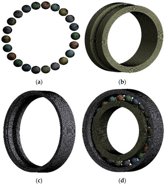
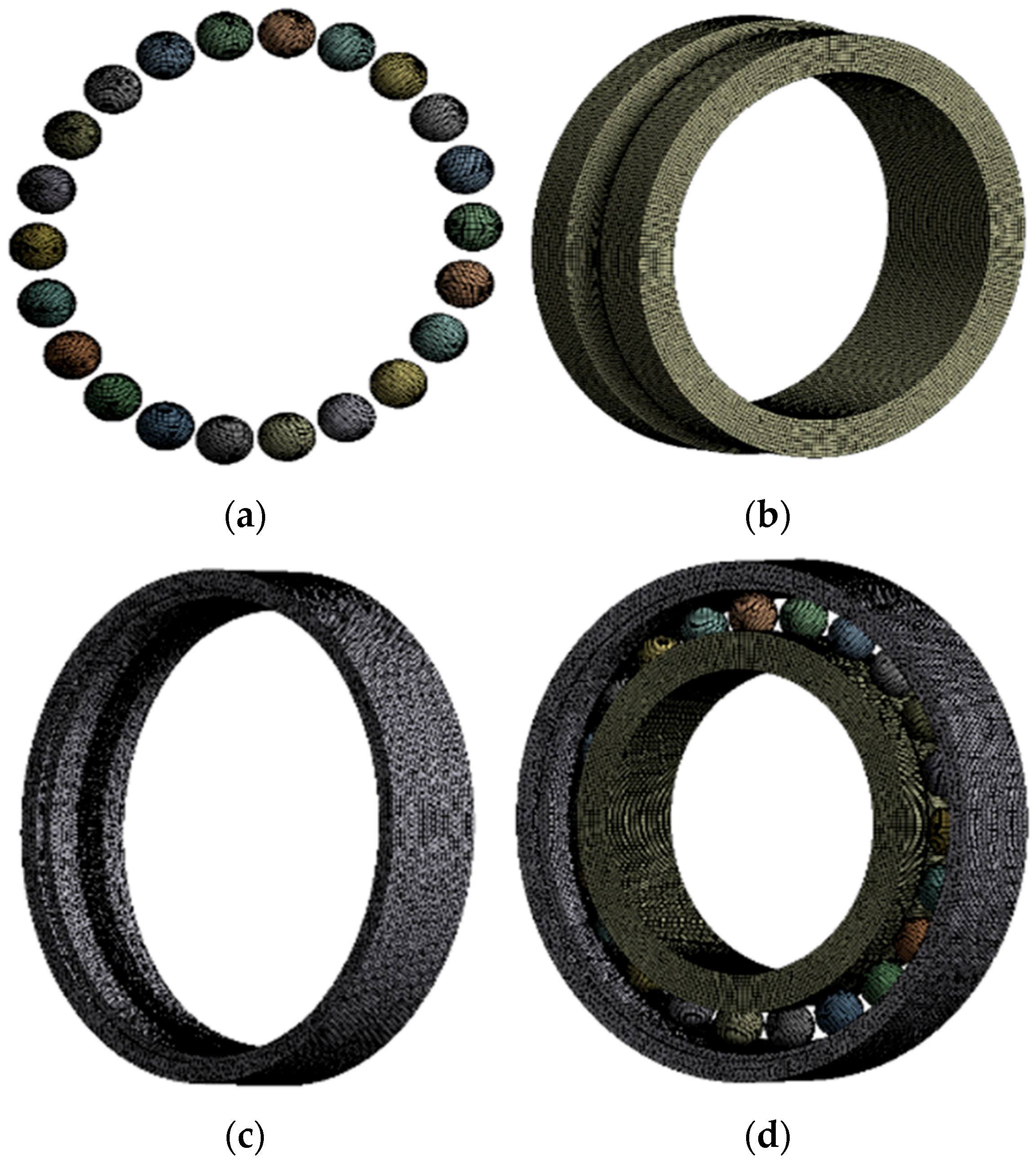
Considering the pronounced rotational symmetry of the major bearing components, the sweep method was applied to meshing annular parts such as the inner and outer rings, while hexahedral elements were used for the rolling elements. In addition, local mesh refinement was performed in the contact regions between the steel balls and the raceways of the inner and outer rings to improve the accuracy of the temperature-field and contact-response calculations. To ensure consistency in the subsequent thermo-mechanical coupling analysis, the same geometric model and meshing strategy were adopted for both the temperature-field analysis and the stress-field analysis. The meshing results are shown in Figure 1.
Figure 1.
(a) Rolling element; (b) Inner ring; (c) Outer ring; (d) Overall model.
3.2.2. Contact and Boundary Conditions
The finite element model for the coupled analysis of the stress field and temperature field of the bearing assembly was developed based on the steady-state temperature-field model. The two analyses employed the same geometric model, mesh discretization, and contact settings. In addition, the loads and constraints required for the structural analysis were applied in the coupling analysis.
- Definition of Contact Pairs
Since contact exists between adjacent components as well as between the rolling elements and the inner and outer rings, contact pairs need to be defined between the interacting parts. For the steady-state thermal analysis, the Bonded contact type is sufficient to meet the analysis requirements, and its linear nature allows relatively high computational efficiency. However, because the coupled-field analysis and the steady-state temperature-field analysis share the same finite element model, the actual contact conditions between interacting components in the structural analysis must also be taken into account. Therefore, the contact pairs between the remaining contacting components were defined as Frictional contacts. For the Frictional contact type, the friction coefficient was set to 0.2, the Augmented Lagrange algorithm was adopted, and the contact treatment was specified as Adjust to Touch.
- 2.
- Definition of Boundary Conditions
The boundary conditions for the steady-state temperature-field analysis should be defined by considering several factors, including the initial temperature, heat generation of the bearing, convective heat transfer coefficient, and thermal radiation emissivity.
First, the initial temperature was set to the ambient temperature of 30 °C. The calculated frictional power losses generated between the inner ring and the steel balls, as well as between the outer ring and the steel balls, were evenly distributed over the steel-ball surfaces and the raceway surfaces of the inner and outer rings. In addition, the frictional power losses arising from the sliding between the cage and the guiding surface, the sliding between the steel balls and the cage, and the viscous losses of the oil film were uniformly assigned to the contact regions between the steel balls and the inner and outer rings. The specific distribution results are presented in Table 3.
Table 3.
Frictional Power Loss Boundary Conditions at Different Bearing Locations.
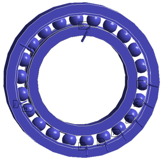
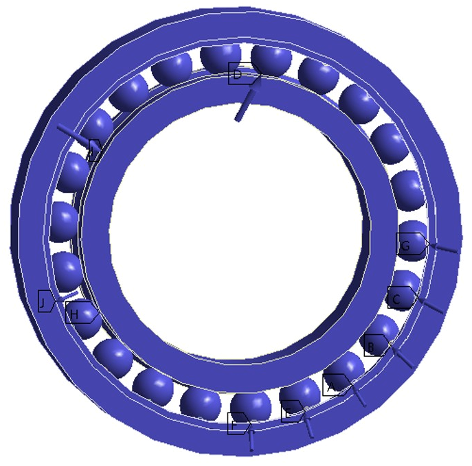
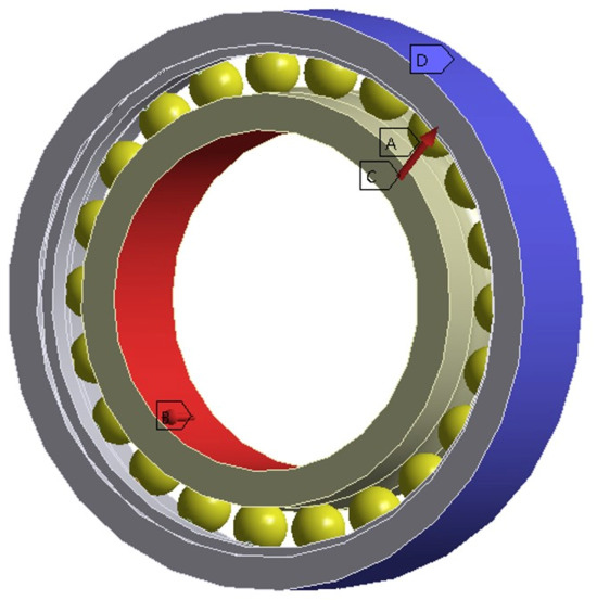
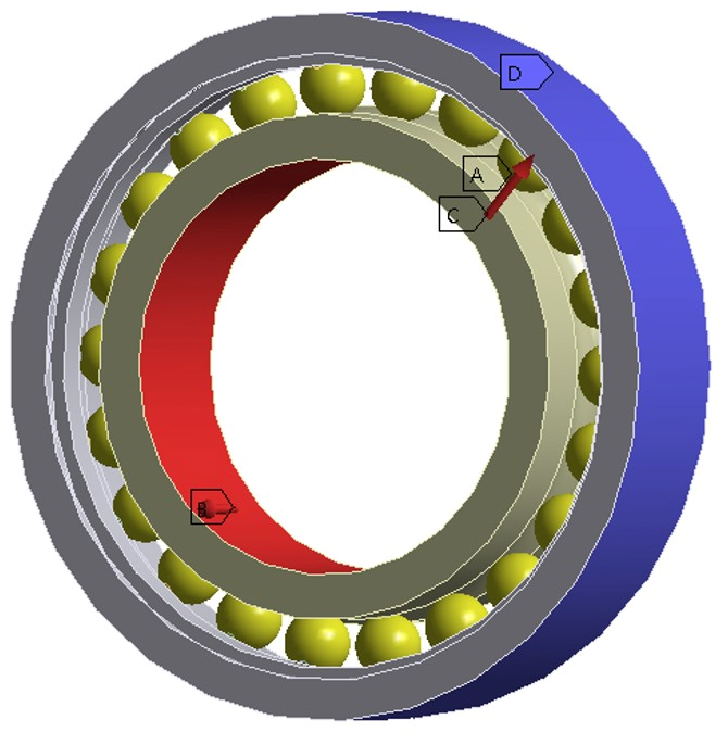
The convective heat transfer coefficient between the steel-ball surfaces, the ring raceway surfaces, and the lubricating oil was specified, and its value was calculated according to Equation (14). The thermal radiation emissivity between the bearing and the external environment was set to 0.87. In addition, the circumferential displacement of the steel balls was constrained to simulate the effect of the cage, as shown in Figure 2 and Figure 3.
Figure 2.
Temperature-Field Boundary Conditions.
Figure 3.
Stress-Field Boundary Conditions.
3.2.3. Simulation Results
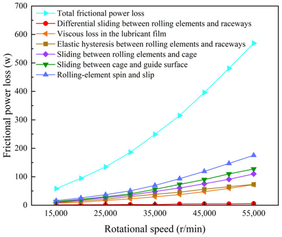
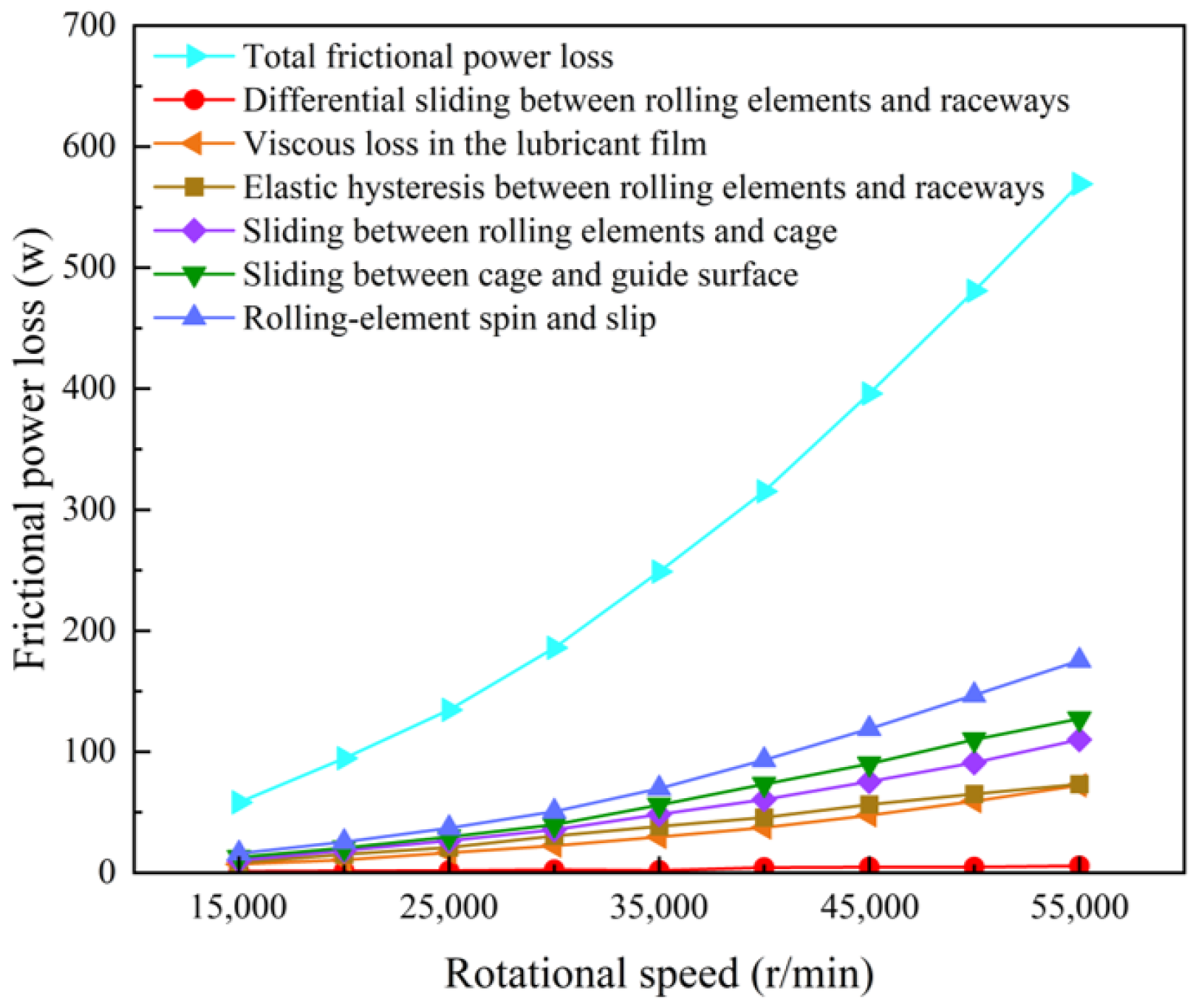
The total frictional power loss of the bearing under different rotational speeds is shown in Figure 4. As the rotational speed increases, all major frictional power-loss components, except for the differential-sliding contribution between the rolling elements and the raceways, increase markedly. This indicates that the differential-sliding loss is comparatively less sensitive to rotational speed under the present loading condition, whereas the other loss components show clear speed dependence. Among them, the rolling-element spin-related friction loss accounts for the largest proportion, representing approximately 31% of the total frictional power loss, which quantitatively confirms that spin/slip-related motion is the dominant contributor to heat generation in the present bearing system. By contrast, the remaining components contribute smaller proportions, although they also increase with speed. Therefore, the increase in total frictional power loss with rotational speed is mainly governed by the speed-sensitive spin-related and lubricant-related dissipation terms rather than by the differential-sliding term alone.
Figure 4.
Bearing friction power consumption at different speeds.
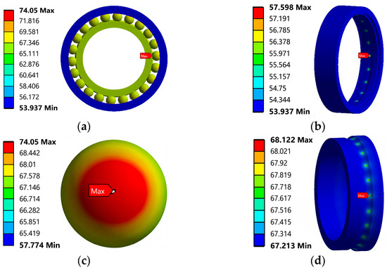
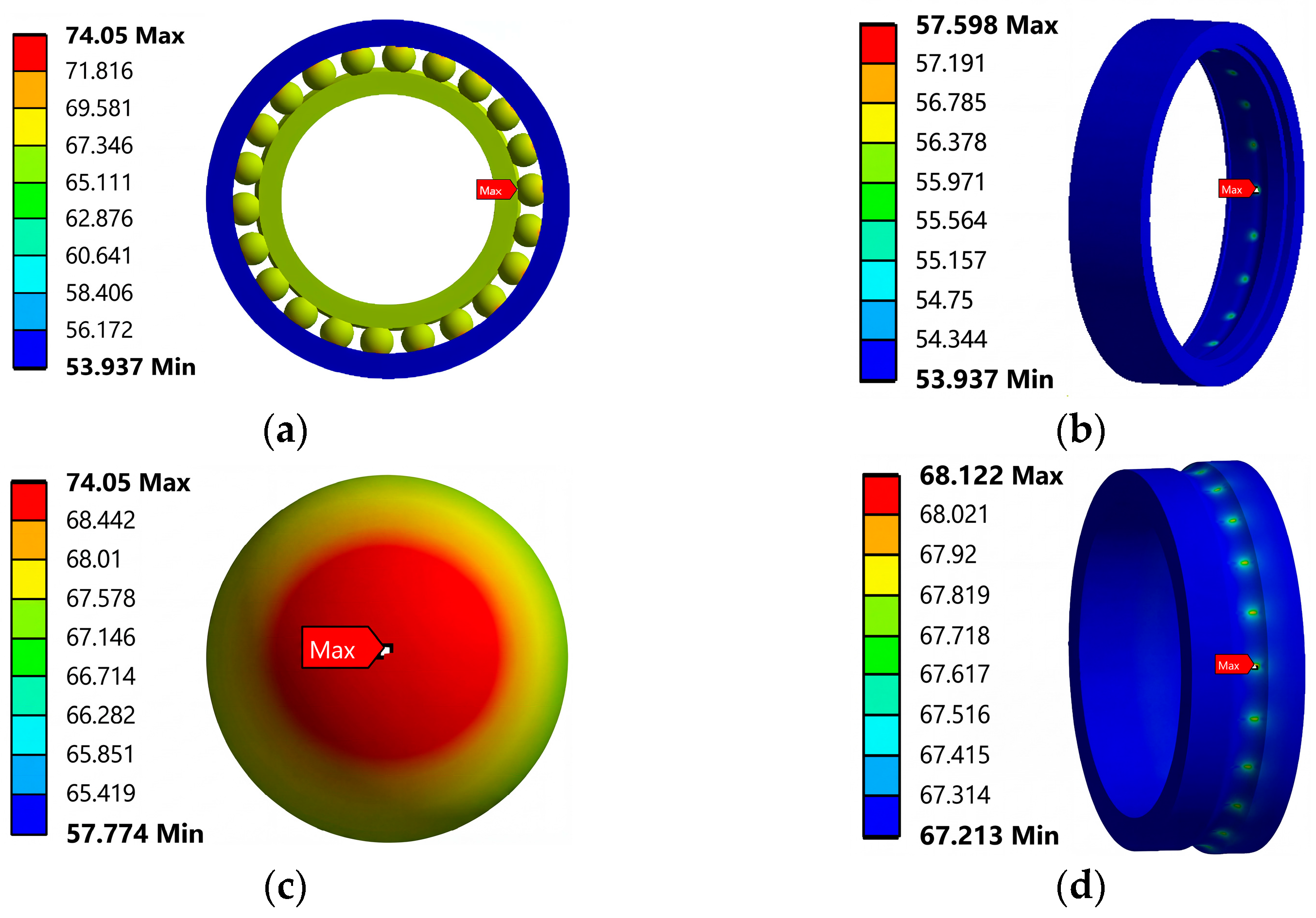
The frictional power loss arising from cage–guide contact, rolling element–cage contact, and lubricant film shear is uniformly distributed over the contact areas between the rolling elements and the inner and outer ring raceways. The steady-state temperature field of the bearing under the specified operating conditions is shown in Figure 5. The temperature is markedly higher in the contact regions between the rolling elements and the rings, as follows: the contact surface temperature of the rolling elements reaches 74 °C, that of the inner ring reaches 68 °C, and that of the outer ring is 57 °C. Heat-source analysis indicates that the frictional power loss at the inner-ring raceway–rolling-element interface is greater than that at the outer-ring raceway–rolling-element interface. In addition, compared with the rings, the rolling elements have poorer local heat-dissipation conditions, so heat is more likely to accumulate in the contact region. As a result, the rolling elements exhibit the highest contact-surface temperature, followed by the inner ring, whereas the outer ring remains the coolest. This indicates that the bearing temperature field under high-speed operating conditions has a pronounced local concentration characteristic, and that the rolling-element/raceway contact zone is the most thermally sensitive region. From an engineering point of view, lubricant supply and local heat dissipation in these contact interfaces should be given particular attention in the design and operation of high-speed spindle bearings in order to avoid local overheating, thermal fatigue, and performance degradation.
Figure 5.
(a) Temperature field of the bearing; (b) Temperature field of the outer ring; (c) Temperature field of the rolling elements; (d) Temperature field of the inner ring.
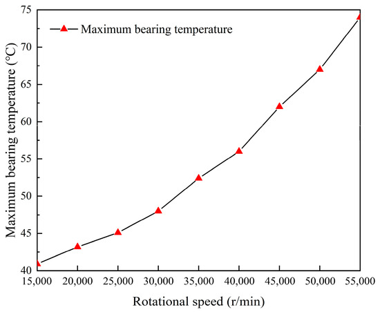
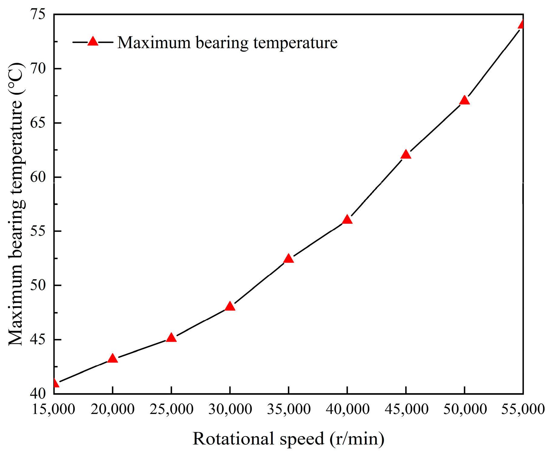
The influence of rotational speed on the maximum bearing temperature is shown in Figure 6. The maximum bearing temperature increases markedly as the rotational speed rises. This is because higher rotational speeds increase the relative spin-related velocity difference in the rolling elements along the raceways, which significantly amplifies the frictional power loss caused by rolling-element spin-slip and further intensifies local heat accumulation in the contact region. As a result, the maximum bearing temperature rises rapidly. When the rotational speed reaches 55,000 r/min, the maximum temperature approaches 75 °C. This indicates that rotational speed is not only a major factor affecting frictional power loss, but also a key variable governing the thermal state of the bearing and the stability of its lubrication condition. For high-speed spindle bearings, the temperature-rise effect induced by increasing rotational speed may further influence contact stress and fatigue life; therefore, temperature control under high-speed operating conditions should be treated as an important consideration in lubricant selection and thermal-management design.
Figure 6.
The variation in the maximum temperature of the bearing with the rotational speed.
3.3. Experimental Validation
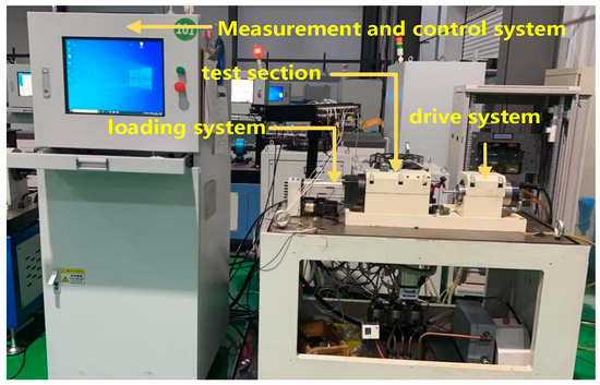
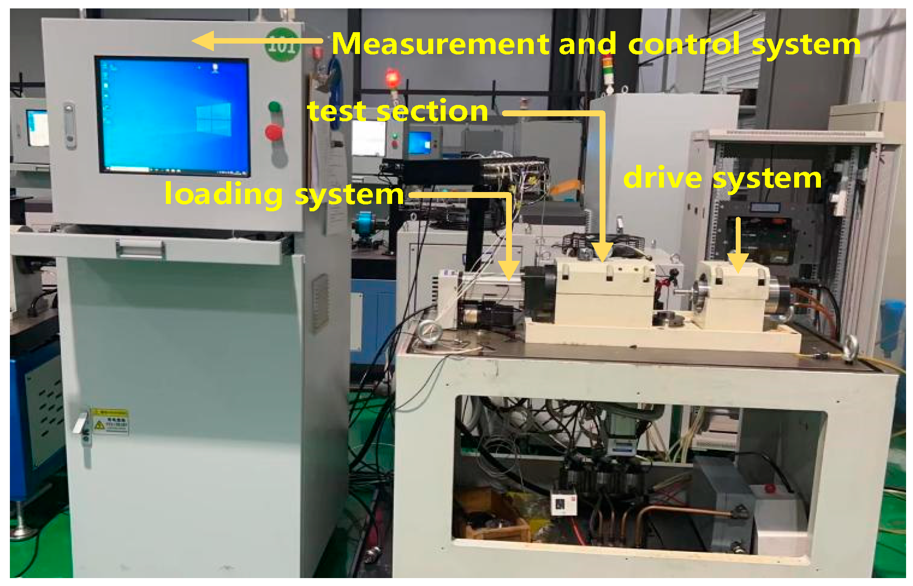
The test apparatus, shown in Figure 7, mainly consists of a loading system, a test section, a drive system, and auxiliary components. In view of the high rotational speed in this study, the angular contact ball bearings are mounted in a face-to-face configuration. The two bearing supports are arranged outside the overhung span of the shaft, so that the large support distance provides high stiffness under axial cantilever loading and excellent resistance to overturning moments. In addition, when the shaft undergoes thermal expansion, the inner and outer rings tend to move apart, which effectively prevents bearing seizure.
Figure 7.
The overall structure of the test system.
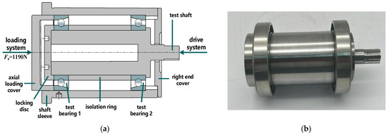
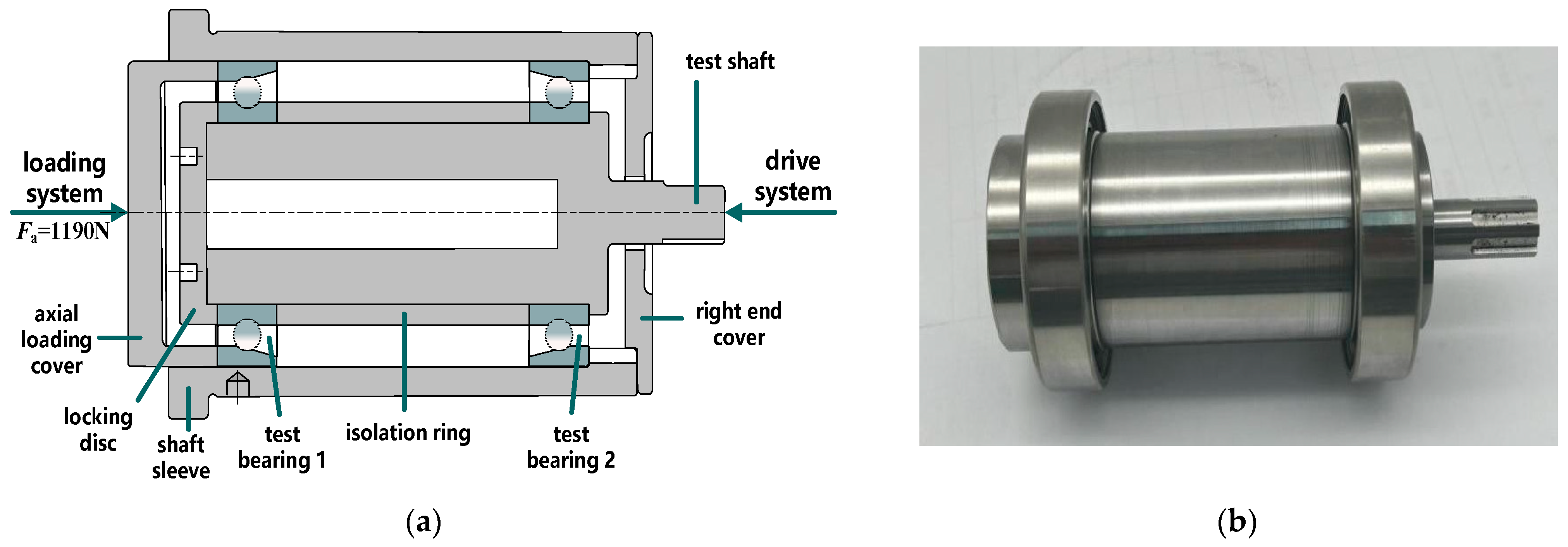
As shown in Figure 8, the test bearing is mounted in a test chamber that mainly comprises the test shaft, isolation ring, shaft sleeve, locking disc, right end cover, and axial loading cover. The test shaft is driven by an electric spindle through a coupling, which in turn drives the rotation of the test bearing. An axial load is applied by a servo electric cylinder and transmitted through the axial loading cover to the outer ring of Test Bearing 1. The load is then transferred from the outer ring to the rolling elements, from the rolling elements to the inner ring, and finally transmitted to Test Bearing 2 through the inner ring.
Figure 8.
(a) Schematic diagram of the test unit; (b) Photograph of the test unit.
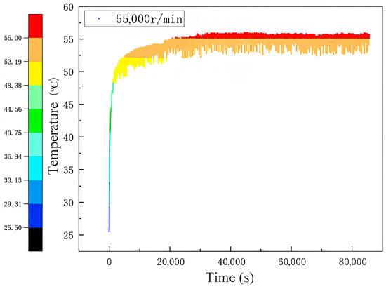
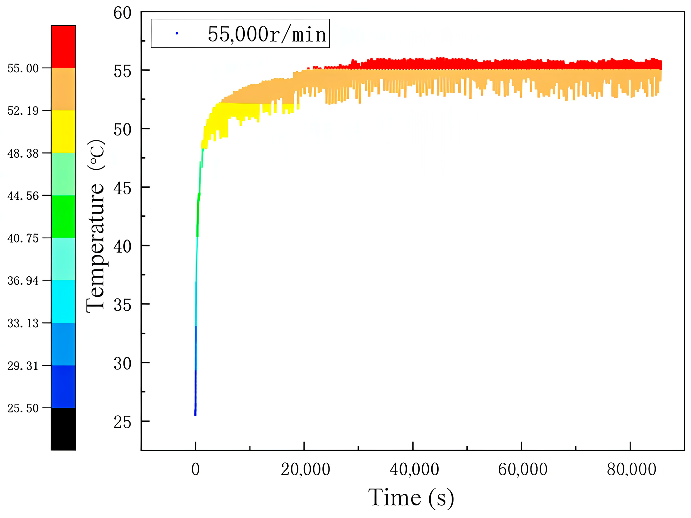
In this study, P2 precision-grade angular contact ball bearings were tested under an axial load of 1190 N. The spindle speed was gradually increased to 55,000 r/min according to the acceleration procedure specified in the relevant standard, and once 55,000 r/min was reached the bearing was operated continuously for 24 h. The outer-ring temperature was monitored in real time by a measurement and control system, while oil–air lubrication was applied continuously to cool the outer ring during the test. The test results are shown in Figure 9. After approximately 8 h of operation, the outer-ring temperature stabilized at about 55 °C. The main purpose of the experimental validation in this study is to verify the predictive capability of the proposed temperature-field model for the thermal response of the bearing. Considering the practical difficulty of directly measuring multiple internal quantities in a high-speed spindle-bearing system, the experiment in the present work mainly focuses on the time-varying outer-ring temperature, which is taken as the primary validation target for the thermal model. Accordingly, the experimental validation in this study is mainly directed toward the bearing temperature response, especially the outer-ring temperature variation.
Figure 9.
Outer ring temperature test data.
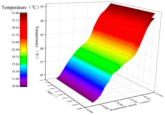
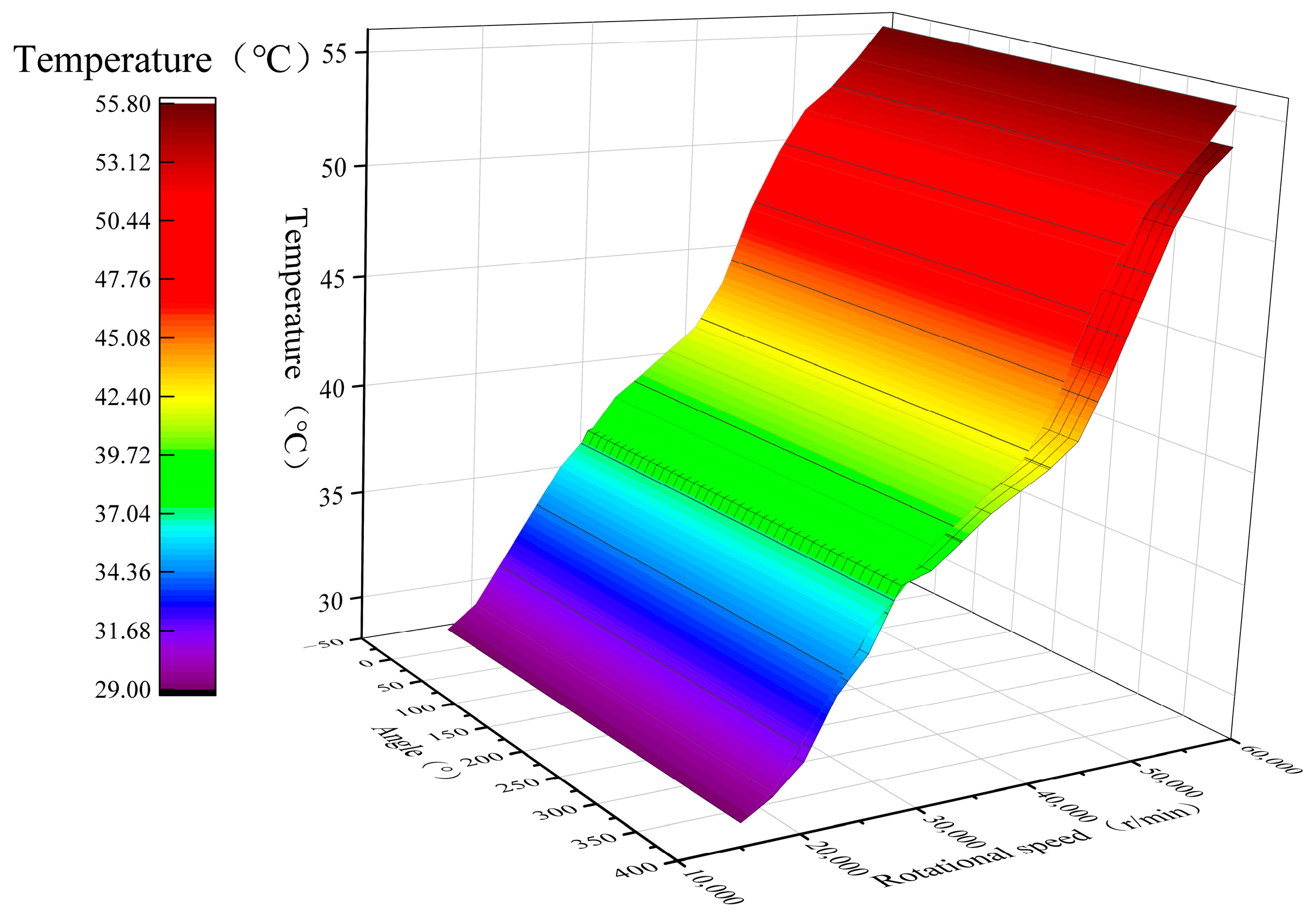
Figure 10 compares the experimental data with the simulation results. The angles shown in the figure correspond to the circumferential positions at which the simulated temperatures are evaluated, with the experimental temperature measurement location taken as 180 °. The maximum experimental temperature is 55.8 °C, whereas the corresponding simulated value is slightly lower at 54.1 °C. This discrepancy may be attributed to uncertainties in the convective heat-transfer coefficient and to errors introduced by the mesh discretization. Overall, good agreement is obtained between the simulation and experiment, with the relative error remaining within 5%, which demonstrates the validity of the thermal analysis model for high-speed ultra-precision machine tool spindle bearings developed in this study.
Figure 10.
Comparison of test results and simulation analysis results.
3.4. Thermal-Mechanical Coupled Field Simulation Analysis of Bearings
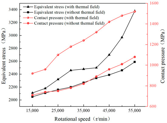
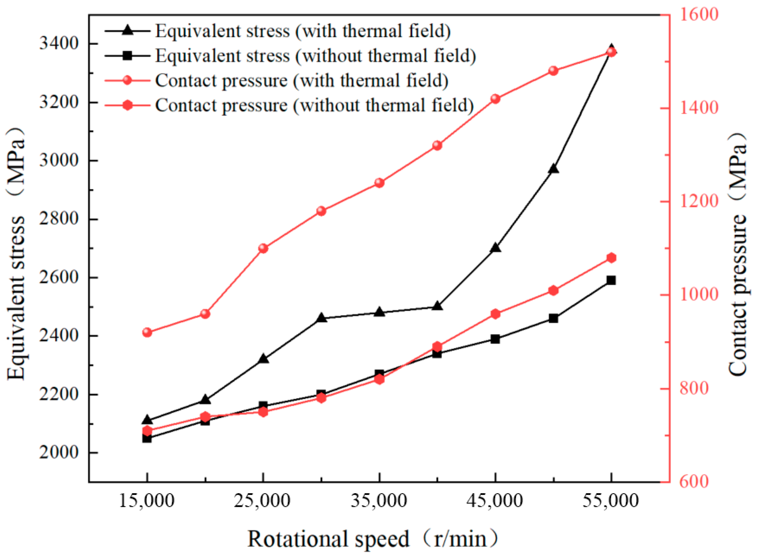
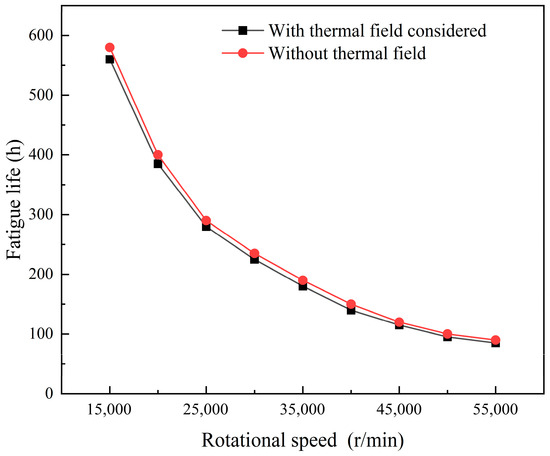
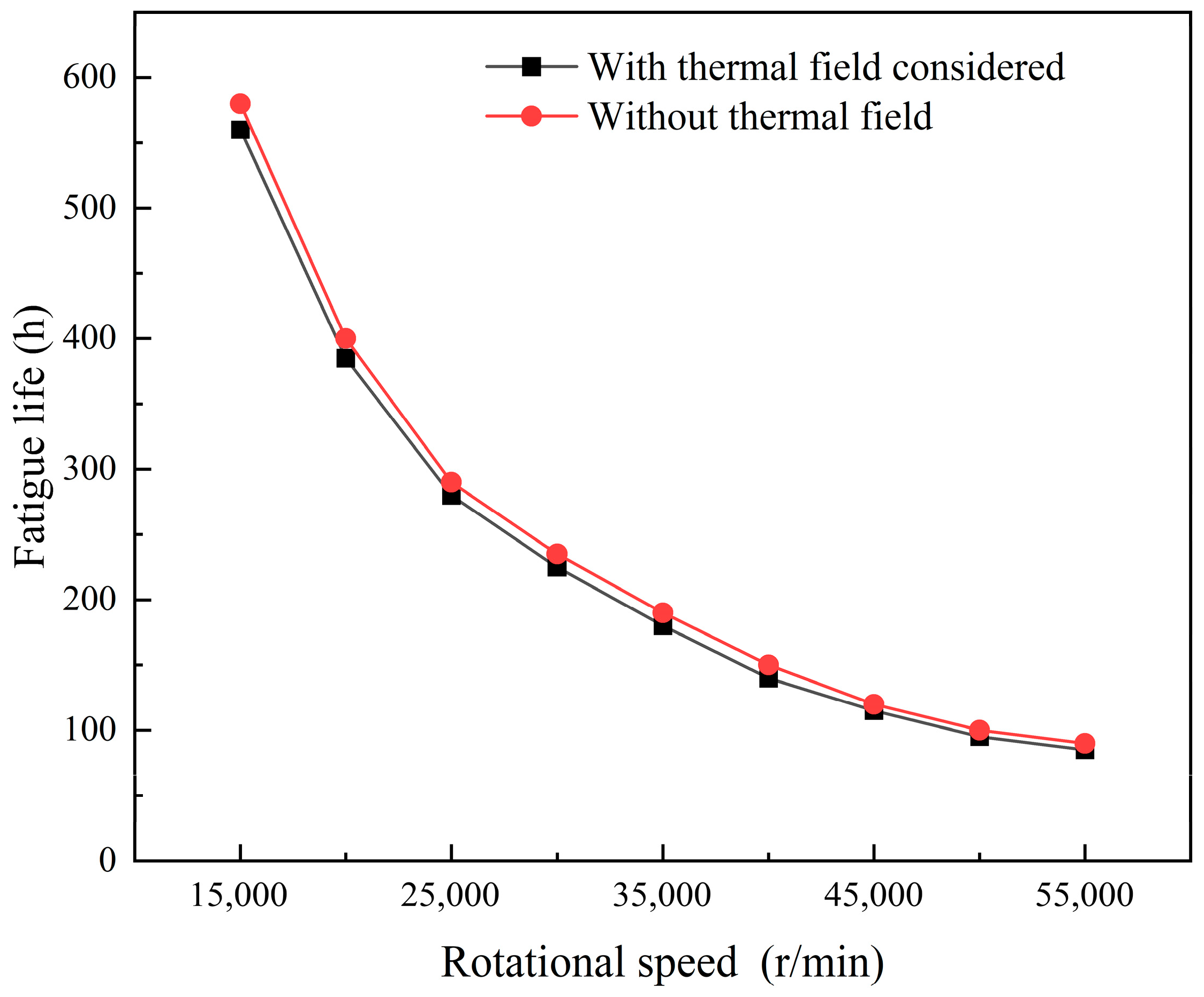
Figure 11 shows the influence of rotational speed on the equivalent stress and contact pressure of the bearing under the specified operating conditions. Both the equivalent stress and the contact pressure increase markedly as the rotational speed rises. The underlying reason is that a higher rotational speed leads to greater frictional power loss, which raises the bearing temperature. Under the action of temperature rise, the bearing rings undergo thermal expansion and thermal deformation, which reduces the internal clearance and further increases the effective interference between the rolling elements and the inner and outer raceways. As a consequence, load concentration in the contact region becomes more severe, and both the equivalent stress and the contact pressure increase simultaneously. Therefore, temperature rise not only changes the thermal state of the bearing, but also further alters its contact-mechanical behavior. This result indicates that, for high-speed ultra-precision spindle bearings, contact and strength evaluation based only on room-temperature conditions may underestimate the local stress risk during actual operation, and thermo-mechanical coupling should therefore be considered in structural design and parameter optimization. Figure 12 illustrates the effect of rotational speed on bearing fatigue life under the same operating conditions. As the rotational speed increases, the bearing fatigue life shows a pronounced downward trend. This is because the increase in rotational speed raises the frictional power loss and causes a higher temperature rise, while the elevated temperature further increases equivalent stress and contact pressure through thermal expansion and changes in the contact state. As a result, fatigue-damage accumulation in the contact region is accelerated, and the bearing life is shortened. Therefore, the reduction in bearing life is not caused by rotational speed alone, but by the combined action chain of increased rotational speed, increased frictional power loss, increased temperature, enhanced thermal deformation, elevated contact stress, and reduced fatigue life. This result suggests that life evaluation of high-speed spindle bearings should incorporate the weakening effect of thermal behavior on contact condition and fatigue performance, rather than relying solely on room-temperature or single-load assumptions.
Figure 11.
The influence of rotational speed on equivalent stress and contact pressure.
Figure 12.
Effect of rotational speed on bearing fatigue life.
The bearing fatigue life discussed in this study is evaluated using a numerical rating-life estimation method for rolling bearings, rather than being obtained from a dedicated fatigue-life test. Under the same reliability assumption, the basic rating life L10 is calculated from the basic dynamic load rating C and the equivalent dynamic load P, and is then converted into the life in hours L10h according to the rotational speed. For ball bearings, the life exponent is taken as p = 3. Therefore, the fatigue-life result reported in this paper is mainly used to compare the relative influence of different rotational speeds on bearing life through thermo-mechanical response variations.
4. Conclusions
This paper develops a thermo–mechanically coupled analysis model for high-speed ultra-precision machine tool spindle bearings and investigates the variations in temperature and thermal stress under different operating conditions. The model provides theoretical guidance for the design of spindle bearings and the selection of suitable lubrication conditions. The findings offer important insights into the performance and optimization of high-speed spindle bearings, as follows:
- Among the friction losses in bearings, those resulting from rolling element spin slippage constitute the largest proportion and therefore warrant greater attention in the design and application of high-speed bearings;
- Under identical operating conditions, the rolling elements exhibit the highest surface temperature, followed by the inner ring, while the outer ring maintains the lowest temperature;
- Temperature has a pronounced effect on bearing stress. Under the same operating conditions, the equivalent stress increases by 21%, the contact pressure rises by 25%, and the bearing fatigue life decreases by 5.6%. Therefore, stress behavior should be regarded as a critical design consideration for high-speed ultra-precision machine tool spindle bearings.
It should also be emphasized that the experimental validation in this study is mainly focused on the outer-ring temperature variation, whereas the frictional power loss, contact pressure, equivalent stress, and fatigue life are mainly obtained from the numerical model. In future work, more systematic experimental investigations involving friction torque, power loss, and bearing life are needed to further validate these model-predicted results and enhance the engineering applicability of the proposed approach.
Author Contributions
Methodology, H.T.; Writing—original draft, D.W.; Writing—review & editing, G.L.; Supervision, H.T. All authors have read and agreed to the published version of the manuscript.
Funding
This research received no external funding.
Data Availability Statement
The data presented in this study are available on reasonable request from the corresponding author due to file size limitations and the complexity of the raw simulation and experimental datasets.
Conflicts of Interest
The authors declare no conflicts of interest.
References
- Huang, X.Y. Rapid tooling technology based on high-speed cutting. Mech. Des. Manuf. 2009, 10, 203–204. [Google Scholar] [CrossRef]
- Li, F.C.; Wang, H.T.; Li, T.M. Research on thermal error modeling and prediction method of heavy CNC machine tools. Chin. J. Mech. Eng. 2016, 52, 154–160. [Google Scholar] [CrossRef] [Scilit]
- Li, X.; Li, H.; Zhang, Y.; Hong, J. Investigation of non-uniform preload on the static and rotational performances for spindle bearing system. Int. J. Mach. Tools Manuf. 2016, 106, 11–21. [Google Scholar] [CrossRef] [Scilit]
- Cai, S.Y.; Gao, Y. Application of thermal error compensation function in the field of machine tools. Intern. Combust. Engines Accessories 2022, 12, 112–114. [Google Scholar] [CrossRef]
- Jin, C.; Wu, B.; Hu, Y. Heat generation modeling of ball bearing based on internal load distribution. Tribol. Int. 2012, 45, 8–15. [Google Scholar] [CrossRef] [Scilit]
- Jones, A.B. A General Theory for Elastically Constrained Ball and Radial Roller Bearings Under Arbitrary Load and Speed Conditions. J. Basic Eng. 1960, 82, 309–320. [Google Scholar] [CrossRef] [Scilit]
- Hernot, X.; Sartor, M.; Guillot, J. Calculation of the Stiffness Matrix of Angular Contact Ball Bearings by Using the Analytical Approach. J. Mech. Des. 2000, 122, 83–90. [Google Scholar] [CrossRef] [Scilit]
- Harris, T.A.; Kotzalas, M.N. Advanced Concepts of Bearing Technology: Rolling Bearing Analysis; CRC Press: Boca Raton, FL, USA, 2006. [Google Scholar]
- Chunjiang, Z.; Xiaokai, Y.; Qingxue, H.; Shidong, G.; Xin, G. Analysis on the load characteristics and coefficient of friction of angular contact ball bearing at high speed. Tribol. Int. 2015, 87, 50–56. [Google Scholar] [CrossRef] [Scilit]
- Than, V.-T.; Huang, J.H. Nonlinear thermal effects on high-speed spindle bearings subjected to preload. Tribol. Int. 2016, 96, 361–372. [Google Scholar] [CrossRef] [Scilit]
- Jin, Y.; Liu, S.J.; Zhang, J.G. Thermal analysis and experimental verification of high speed angular contact ball bearing. Bearing 2018, 12, 30–33+38. [Google Scholar] [CrossRef]
- Hu, X.Q.; Chen, W.F. Thermal characteristics analysis and test of angular contact ball bearing. J. Xi’an Jiaotong Univ. 2015, 49, 106–110. [Google Scholar] [CrossRef]
- Wang, Y.M.; Wang, H.D.; Cui, Y.C. Research on thermal characteristics of double row tapered roller bearings considering modification. Electromechanical Eng. 2023, 40, 1345–1353. [Google Scholar] [CrossRef]
- Hu, P.F.; Luo, J.L.; Luo, B.; Feng, W.M.; Tang, D.W. Research on Thermal-Mechanical Coupling Characteristics of High-Speed Motorized Spindle Angular Contact Ball Bearings. Dev. Innov. Electromechanical Prod. 2023, 36, 76–79. [Google Scholar] [CrossRef]
- Zhao, C.Y.; Hou, S.L.; Li, Z.J. Thermal analysis of angular contact ball bearings installed in pairs in feed system. J. Northeast. Univ. (Nat. Sci. Ed.) 2020, 41, 700–705. [Google Scholar] [CrossRef]
- Li, Z.J.; Zhao, C.Y. Thermal-mechanical coupling analysis of angular contact ball bearings in feed system. China Mech. Eng. 2023, 34, 821–829. [Google Scholar] [CrossRef]
- Li, J.S.; Yuan, Y.; Hao, D.Q. Analysis and experimental study on bearing temperature rise of high speed machine tool. Mech. Transm. 2023, 47, 129–136. [Google Scholar] [CrossRef]
- Wang, Z.K.; Wang, J.; Wang, S.J. Research on temperature rise characteristics of railway freight car bearings. Sci. Technol. Eng. 2023, 23, 5067–5075. [Google Scholar] [CrossRef]
- Jiang, B.G.; Lie, Q.; Du, J.J. Thermal characteristics analysis of high-speed ball bearing motorized spindle. Lubr. Seal. 2017, 42, 6–12, 18. [Google Scholar] [CrossRef]
- Wang, Y.S.; Zhu, H.F.; Liu, Z. Finite element analysis of temperature field of shaft bearing. Aeronaut. Dyn. 2012, 27, 1146–1152. [Google Scholar]
- Cao, S.S.; Yang, H.S.; Luo, B. Dynamic analysis of aero-engine spindle ball bearings with thermal-mechanical coupling. J. Aerosp. Power 2024, 39, 20220890. [Google Scholar] [CrossRef]
- Yu, Y.; Ma, R.; Xue, Y.; Liu, Y. Study on Thermal Characteristics of Angular Contact Ball Bearings Considering Roundness Error. Lubricants 2024, 12, 43. [Google Scholar] [CrossRef] [Scilit]
- Kim, D.; Kim, M.; Ryu, G.; Park, J. On Heat, Temperature, and Cavity Oil Volume Fraction of an Under-Race Lubricated Angular Contact Ball Bearing. Tribol. Int. 2023, 187, 108715. [Google Scholar] [CrossRef] [Scilit]
- Darul, L.; Touret, T.; Changenet, C.; Ville, F. Power Loss Analysis of an Oil-Jet Lubricated Angular Contact Ball Bearing: Theoretical and Experimental Investigations. Lubricants 2024, 12, 14. [Google Scholar] [CrossRef] [Scilit]
- Guo, J.; Ma, B.; Cheng, Z.; Xu, H.; Li, S.; Zou, T.; Meng, F. Modified Quasi-Static Analysis of Angular Contact Ball Bearing. Tribol. Int. 2026, 214, 111198. [Google Scholar] [CrossRef] [Scilit]
- Zhang, X.; Zhao, D.; Ma, S.; Zhang, X.; Yan, K. Thermal-Mechanical Coupled Interaction of Angular Contact Ball Bearing Considering Combined Deformation. Tribol. Int. 2025, 212, 110994. [Google Scholar] [CrossRef] [Scilit]

Disclaimer/Publisher’s Note: The statements, opinions and data contained in all publications are solely those of the individual author(s) and contributor(s) and not of MDPI and/or the editor(s). MDPI and/or the editor(s) disclaim responsibility for any injury to people or property resulting from any ideas, methods, instructions or products referred to in the content. |
© 2026 by the authors. Licensee MDPI, Basel, Switzerland. This article is an open access article distributed under the terms and conditions of the Creative Commons Attribution (CC BY) license.