


Abstract
Cavitation of oil film is harmful for all kinds of hydrostatic bearings, so the method to avoid cavitation in hydrostatic thrust bearings by optimizing the structure of bearings is proposed in this study. Based on the pressure distribution expressions of two kinds of hydrostatic thrust bearings (circular recess and no recess), considering the boundary conditions of pressure distribution, the threshold conditions to avoid cavitation are obtained. The reliability of these threshold conditions is illustrated by applying the threshold conditions to calculate the pressure distributions of hydrostatic thrust bearings. For hydrostatic thrust bearings with a non-dimensional recess radius larger than 0.607, an appropriate choice on the value of film thickness ratio could effectively avoid cavitation. If the non-dimensional recess radius of bearings is less than 0.607, the inertial parameter has a threshold value determined by recess radius, radius of supply hole, and film thickness ratio. For the bearing with no recess, the threshold value of inertial parameter is only determined by the radius of supply hole. And the results in this study could be applied for the design of hydrostatic thrust bearing to avoid cavitation.
1. Introduction
Hydrostatic bearings serve as critical components in various rotating machinery due to their advantages of low friction and minimal wear [1,2,3]. Considering the direction of loading capacity, there are two kinds of hydrostatic bearings: journal bearings for the loading capacity on the radial direction [4,5] and thrust bearings with the axial load [6,7]. For the hydrostatic thrust bearing with single recess (circular [8] or annular recess [9]), considering the inertial effect, the analytical expressions of static performance parameters, such as pressure distribution, flow rate, and loading capacity, could be deduced by applying the axial symmetry of oil film [8,9]. With this method, many studies discussed on the performance of hydrostatic thrust bearings, such as hydrostatic thrust bearings with non-Newtonian lubricants [10,11,12,13], the hydrostatic thrust bearing considering surface roughness [14,15,16], etc.
The performance of these bearings primarily depends on maintaining a continuous oil film. However, during high-speed operation, oil film rupture can occur, leading to cavitation phenomena. This effect is particularly pronounced in hydrostatic thrust bearings, where inertial forces significantly increase the likelihood of cavitation [17,18,19]. Since cavitation substantially impacts both static and dynamic characteristics of hydrostatic thrust bearings [20], a thorough investigation of this phenomenon is essential for optimal bearing performance.
In recent years, many studies have been done to analyze the cavitation in hydrostatic thrust bearings. Li et al. [21] proposed a new kind of hydrostatic thrust bearing using water as lubricant and discussed the influence of cavitation on the performance of bearings. Considering cavitation and surface structure, Feng et al. [22] established a turbulence model to study the performance of hydrostatic bearings lubricated with water. The results showed that the influence of cavitation and turbulence on the static performance of bearings cannot be ignored. To discuss the evolution process of cavitation in hydrostatic thrust bearings with water lubricant, a cavitation model was given by Lin et al. [23], and experiments had been done to verify the model. It was found that cavitation would be affected by the surface structure of bearings. To investigate the influence of cavitation on the performance of hydrostatic thrust bearings, Song et al. [24] obtained the static performance of bearings through numerical simulation, and the results were verified by experiment. It was found that the load capacity of bearings would be weakened by the cavitation. Lin et al. [25] developed a cavitation model of hydrostatic thrust bearings considering thermal and turbulent effects. The results indicated that the cavitation would weaken the load capacity and friction torque of oil film. Moreover, the temperature rise of oil film would be reduced by cavitation. Yan et al. [26] discussed the effect of cavitation on the vibration of hydrostatic thrust bearings; it was found that the cavitation of oil film was an important reason for the vibration of bearings. Kailei et al. [27] established a cavitation model to discuss the performance of hydrostatic thrust bearings with spiral grooved surface. The model had high computational efficiency and was examined by the experiment. Chen et al. [28] analyzed the influence of cavitation on the hydrodynamic behavior of conical hydrostatic thrust bearings and found the performance of bearings could be improved by an appropriate structure of groove. Zhang et al. [29] discussed the performance of hydrostatic thrust bearings by applying a turbulent model considering the cavitation of oil film. The results illustrated that the influence of cavitation cannot be ignored when the value of Reynolds number was larger than 0.3. Zhang et al. [30] investigated the cavitation caused by the surface structure of hydrostatic thrust bearings. The experimental results showed that the Jakobsson-Floberg-Olsson cavitation model was more accurate than the Reynolds model.
It could be found that the aforementioned studies have primarily focused on the discussions about the influences of cavitation on the performance of hydrostatic thrust bearings, and there are no studies to investigate how to avoid cavitation in hydrostatic thrust bearings. Thus, the method to present cavitation is proposed in this study. With discussing the pressure distribution curve of hydrostatic thrust bearings, it is found that the cavitation could be avoided by designing appropriate geometric structure of hydrostatic thrust bearings.
2. Materials and Methods
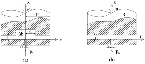
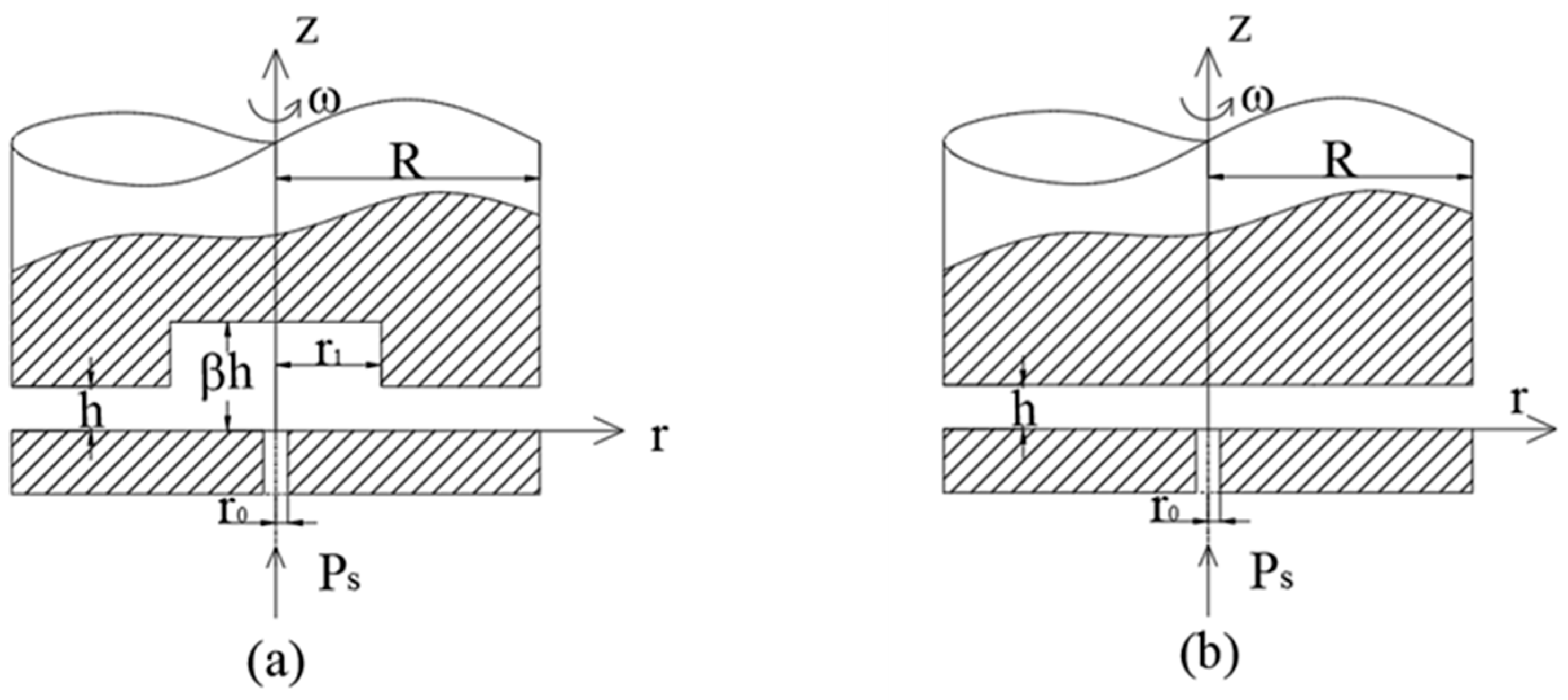
The structures of hydrostatic thrust bearings discussed in this study are displayed in Figure 1. The geometric structural parameters of bearings are: r and z are coordinates on radial and axial direction, respectively, R is radius of the bearing, r0 is radius of the supply hole, r1 is radius of the recess, h is the thickness of oil film, and β is the parameter to illustrate the recess depth. Angular velocity of the bearing is ω, and Ps is the supply pressure. For the hydrostatic thrust bearing in Figure 1a, considering the inertia effect of oil film on the whole region, the pressure distribution of oil film is [31]:
Figure 1.
The structures of hydrostatic thrust bearings: (a) the bearing with circular recess; (b) the bearing with no recess.
Here, β is film thickness ratio, and the definition is the ratio of film thickness in recess region and land region. As illustrated in Figure 1a, it could be found that the value of β should not be less than 1. When the value of β is equal to 1, the hydrostatic thrust bearing is changed into the bearing with no recess, as illustrated in Figure 1b. At this situation, pressure distribution of the bearing is [31]:
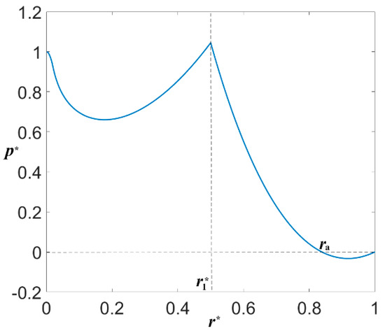
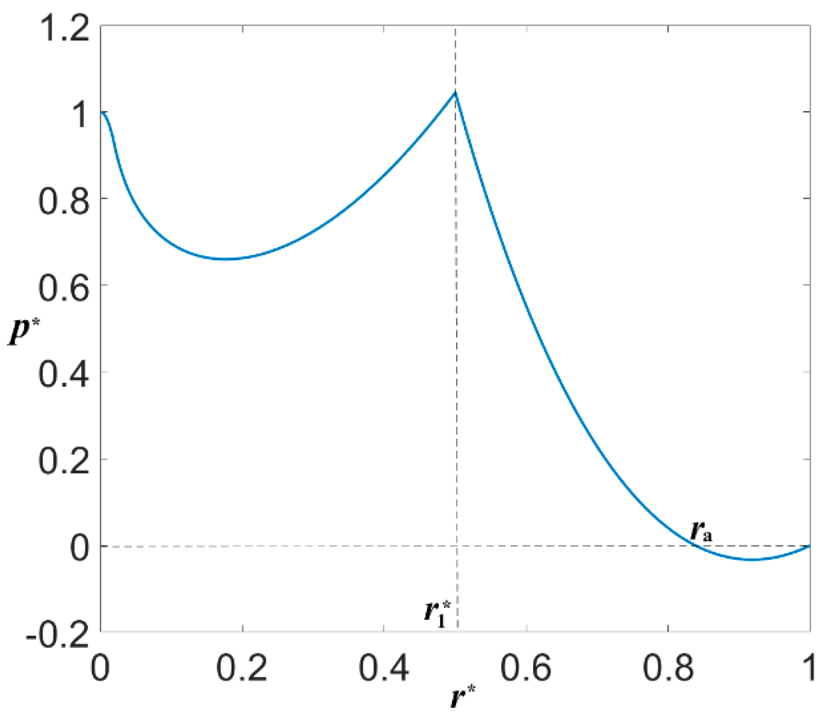
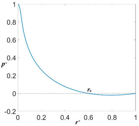
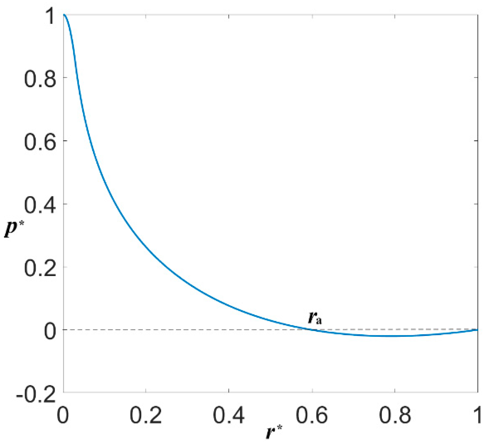
For the hydrostatic thrust bearing in Figure 1a with = 0.5, = 0.02, β = 3, and S = 2.5, the pressure distribution of oil film is displayed in Figure 2. And the pressure distribution of the hydrostatic thrust bearing with no recess is illustrated in Figure 3, the parameters of the bearing are: = 0.03 and S = 0.25. In Figure 2 and Figure 3, it could be found that the pressure is negative in the region ra < r* < 1. It means that the cavitation of oil film has appeared in this region. For hydrostatic bearings, cavitation would cause the unstable of oil film and affect the performance of bearings. Thus, the cavitation of oil film in hydrostatic bearing should be avoided.
Figure 2.
Pressure distribution of the hydrostatic thrust bearing with circular recess: = 0.5, and = 0.02, β = 3 and S = 2.5.
Figure 3.
Pressure distribution of the hydrostatic thrust bearing with no recess: = 0.03 and S = 0.25.
Case 1 the hydrostatic thrust bearing with circular recess
In Figure 2, it could be observed that cavitation has happened in the region of bearing land ( < r < 1). With the boundary condition of pressure distribution , the pressure of oil film in the region of bearing land ( < r < 1) first decreases and then increases. To avoid cavitation in this region, the curve of pressure distribution in this region should be monotone decreasing. That means that the derivative of pressure distribution, with respect to coordinate r,* should be less than 0:
In the Inequation (6), S is the inertial parameter of hydrostatic thrust bearings, and its value is larger than 0, the values of and are between 0 and 1, the value of β is larger than 1, and the value of coordinate r* is between and 1. Then, the Inequation (6) could be changed into:
To avoid the cavitation of oil film, the Inequation (7) should be satisfied for all the values of coordinate r* between and 1. Thus,
And the Inequation (8) could be changed into
Here, g is an expression about parameters , and β is as follows:
As the values of β and S are both larger than 0, so long as the value of expression g is larger than 0, the Inequation (9) could be satisfied. At this situation, the following inequations should be satisfied:
Here, e is the natural constant. If the value of expression g is less than 0, the inertial parameter of hydrostatic thrust bearing S should be satisfied:
Thus, when the structure parameters , , and β of hydrostatic thrust bearings have satisfied the Inequations (11) and (12), the oil film of bearings would be no cavitation no matter how much larger the inertial parameter is. If the parameters , , and β of hydrostatic thrust bearings are not satisfied with Inequations (11) and (12), the inertial parameter of hydrostatic thrust bearings should satisfy Inequation (13), i.e., the inertial parameter has a maximum value. At this situation, to avoid the cavitation of oil film, the inertial parameter of bearings should be less than the maximum value. As angular velocity of the bearing is in direct proportion to the inertial parameter, there is a threshold speed for the hydrostatic thrust bearing. And the threshold speed is:
Case 2 the hydrostatic thrust bearing with no recess
In Figure 3, the pressure distribution of the hydrostatic thrust bearing with no recess is first a decrease and then an increase, and the cavitation of oil film has appeared in the region of ra < r* < 1. Considering the boundary condition of pressure distribution , to avoid the cavitation of oil film, the curve of pressure distribution in region < r* < 1 should be monotone decreasing. And the following inequation could be obtained:
As the value of r* is larger than 0, the Inequation (15) could be changed into
The expression at left of the Inequation (16) is an increasing function with respect to r* in the region < r* < 1. To make sure that the Inequation (16) is satisfied, the following inequation should be satisfied:
As the value of is less than 1, the Inequation (17) could be changed into
Thus, for the hydrostatic thrust bearing with no recess, to avoid the cavitation of oil film, the inertial parameter S and the radius of supply hole should satisfy the Inequation (18). And threshold speed of the hydrostatic thrust bearing with no recess is:
3. Illustration of Reliability
The critical conditions to avoid the cavitation of oil film for hydrostatic thrust bearings are deduced in this study. To illustrate the validity of the derivation, the pressure distributions of hydrostatic thrust bearings are displayed by applying these critical conditions. The reliability is illustrated by whether the cavitation appears or not when the structure of hydrostatic bearings satisfies the threshold conditions. Similar with the derivative process, the illustration is shown in two parts, too.
Case 1 the hydrostatic thrust bearing with circular recess
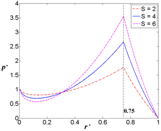
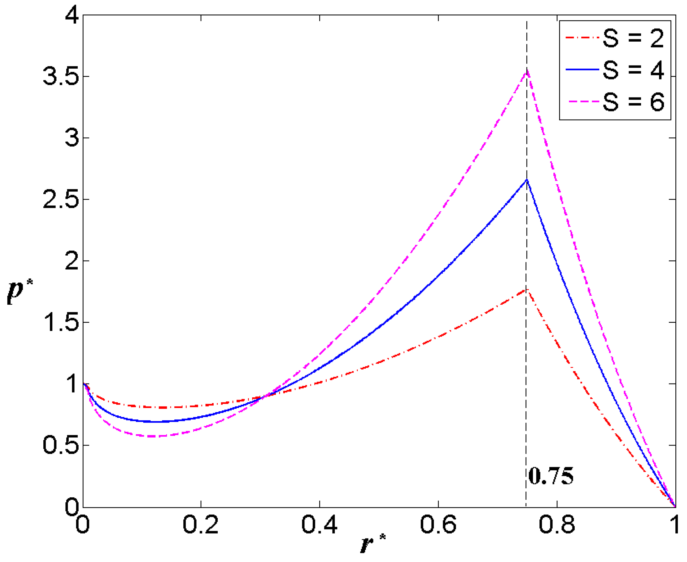
For the hydrostatic thrust bearing with circular recess, considering the critical conditions (11) and (12), setting the value of recess radius = 0.75, the radius of supply hole = 0.02. At this situation, the recess depth parameter β should be larger than 3.05, the value of β = 4, and the inertial parameter is S = 2, 4, 6. The pressure distribution is displayed in Figure 4; it could be found that there are no cavitations for the hydrostatic thrust bearing.
Figure 4.
The pressure distribution of hydrostatic thrust bearings: = 0.75, = 0.02, β = 4, and S = 2, 4, 6.
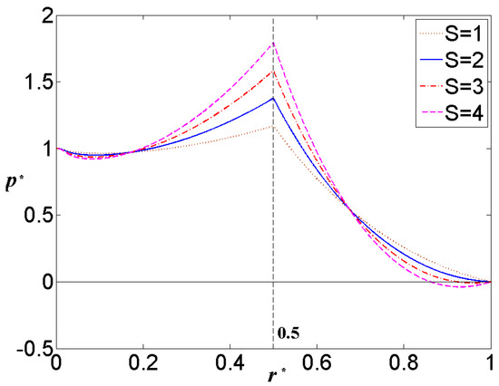
Considering the other situation of critical condition (13), setting the value of recess radius = 0.5, the radius of supply hole = 0.02, the recess depth parameter β = 5. At this situation, the inertial parameter S should be larger than 2.24, and the value of S = 1, 2, 3, 4. The pressure distribution of hydrostatic bearings is illustrated in Figure 5. It could be found that there are no cavitations for the value of inertial parameter S less than the threshold value 2.24, such as S = 1 and 2. Once the value of inertial parameter S is larger than the threshold value 2.24, such as S = 3 and 4, the cavitation would happen. And with a larger value of inertial parameter S, the region of cavitation is larger, too.
Figure 5.
The pressure distribution of hydrostatic thrust bearings: = 0.5, = 0.02, β = 5, and S = 1, 2, 3, 4.
Thus, with the discussions on the results in Figure 4 and Figure 5, it could be found that the critical conditions in Inequations (11)–(13) to avoid the cavitation of oil film in hydrostatic thrust bearings are reliable.
Case 2 the hydrostatic thrust bearing with no recess
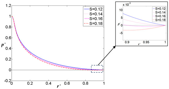
For the hydrostatic thrust bearing with no recess, there is only one structure parameter, which is the radius of supply hole . Setting the value of = 0.03, applying the critical condition (18), the value of inertial parameter S should be 0.143. To illustrate the validity of critical condition (18), set S = 0.12, 0.14, 0.16, and 0.18. The pressure distribution of hydrostatic thrust bearings with no recess is displayed in Figure 6. It could be found that there are no cavitations for the value of inertial parameter S less than the threshold value 0.143, such as S = 0.12 and 0.14. Once the value of inertial parameter S is larger than the threshold value 0.143, such as S = 0.16 and 0.18, the cavitation would happen. And with a larger value of inertial parameter S, the region of cavitation is larger, too. Thus, the critical condition in Inequation (18) to avoid cavitation in hydrostatic thrust bearings with no recess is reliable.
Figure 6.
The pressure distribution of hydrostatic thrust bearings: = 0.03 and S = 0.12, 0.14, 0.16, 0.18.
4. Results and Discussion
The preceding analysis demonstrates that cavitation in hydrostatic thrust bearings can be effectively prevented through optimal selection of structural and inertial parameters. For the hydrostatic thrust bearing with circular recess, if the structure parameters of bearings satisfy Inequations (11) and (12), or the structure parameters and the inertial parameter of bearings satisfy Inequation (13), there would be no cavitation. For the hydrostatic thrust bearing with no recess, if the structure parameters and inertial parameter of bearings satisfy Inequation (18), the cavitation of oil film would not appear.
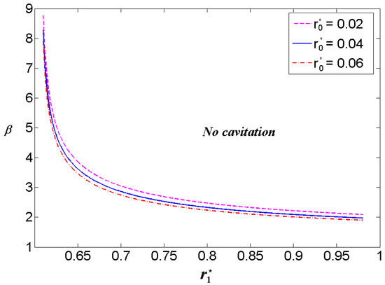
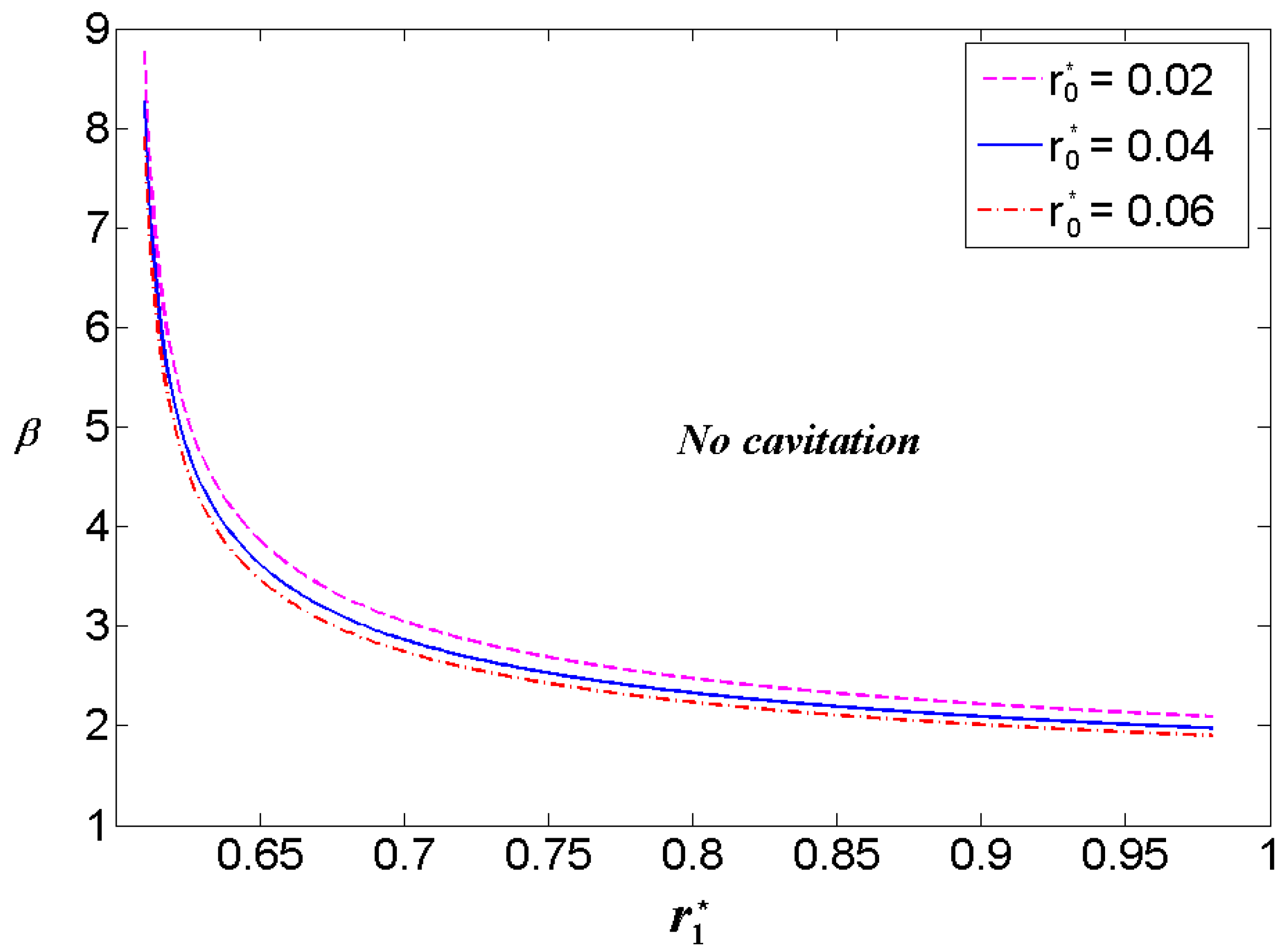
In the design of circular recess hydrostatic thrust bearings, cavitation can be prevented through careful optimization of geometric structure parameters. The appropriate geometric structure of bearings is displayed in Figure 7. Firstly, the recess radius should be larger than 0.607. Then, the value of recess depth parameter β should be in the upper region of the curve in Figure 7. It is found that the influence of supply hole radius on the cavitation is subtle, and a shallow recess should match a large recess radius.
Figure 7.
The appropriate geometric structure of hydrostatic thrust bearings to avoid cavitation.
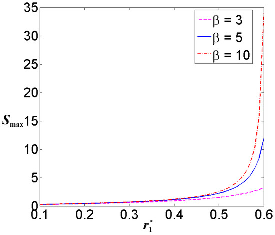
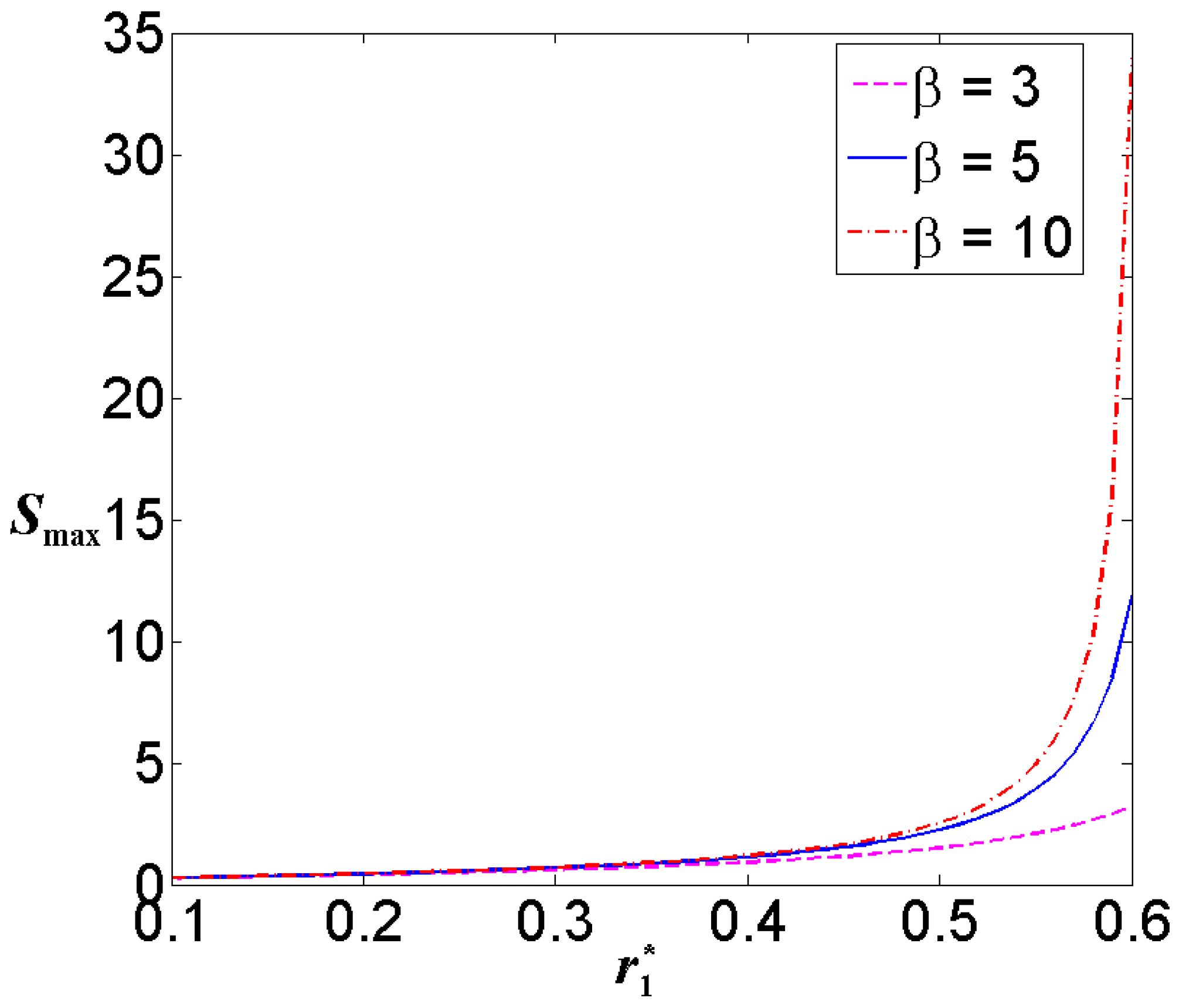
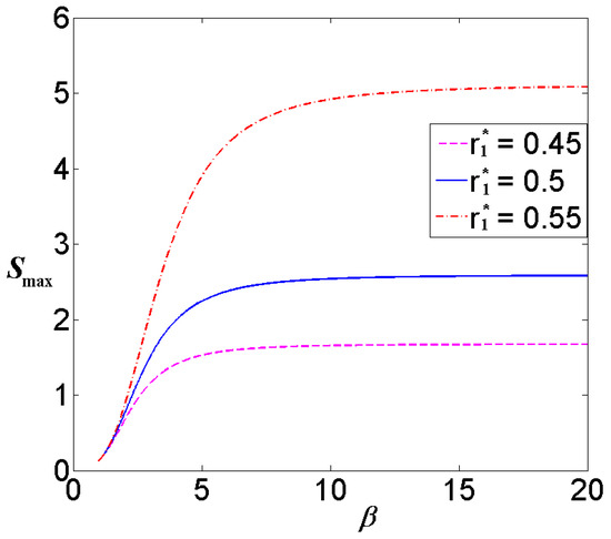
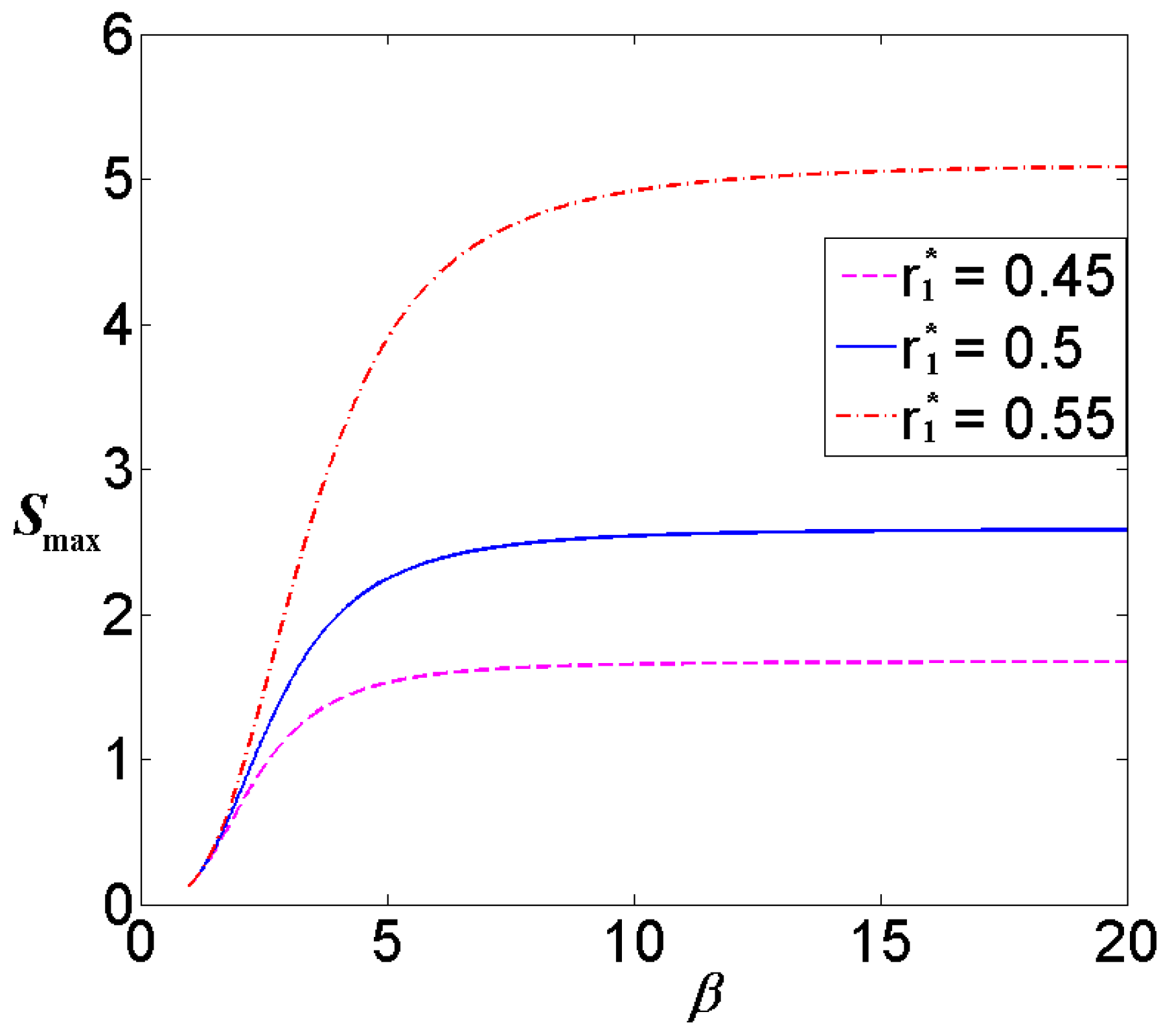
If the geometric structure parameters hydrostatic thrust bearings with circular recess do not satisfy the Inequations (11) and (12), the inertial parameter S should be less than the threshold value Smax. The influence of the geometric structure parameters on the threshold value of the inertial parameter Smax is illustrated in Figure 8 and Figure 9, and the radius of supply hole = 0.02. In Figure 8, the relationship between the threshold value Smax and recess radius is displayed. For a bearing with a larger recess radius, the threshold value Smax is larger, too. When the depth of recess is larger, the influence of recess radius on the threshold value Smax is more obvious, especially for the value of recess radius larger than 0.5. The influence of film thickness ratio β on the threshold value Smax is illustrated in Figure 9. When the film thickness ratio β is larger, the threshold value Smax is larger, too, and for the bearing with a lager recess radius, the influence of film thickness ratio β on the threshold value Smax is more obvious. With the increase of film thickness ratio β, the gradient of threshold value Smax, with respect to film thickness ratio β, decreases. When the value of film thickness ratio β is larger than 15, the influence of film thickness ratio β on the threshold value Smax is quite weak.
Figure 8.
The relationship between the threshold value of the inertial parameter Smax and recess radius .
Figure 9.
The relationship between the threshold value of the inertial parameter Smax and film thickness ratio β.
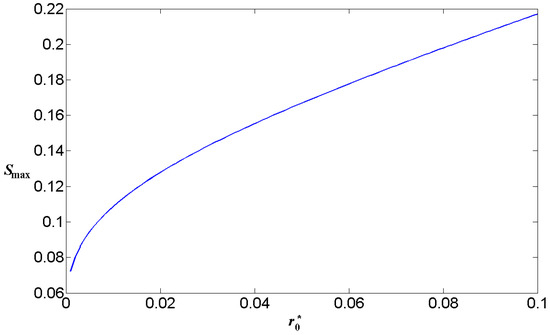
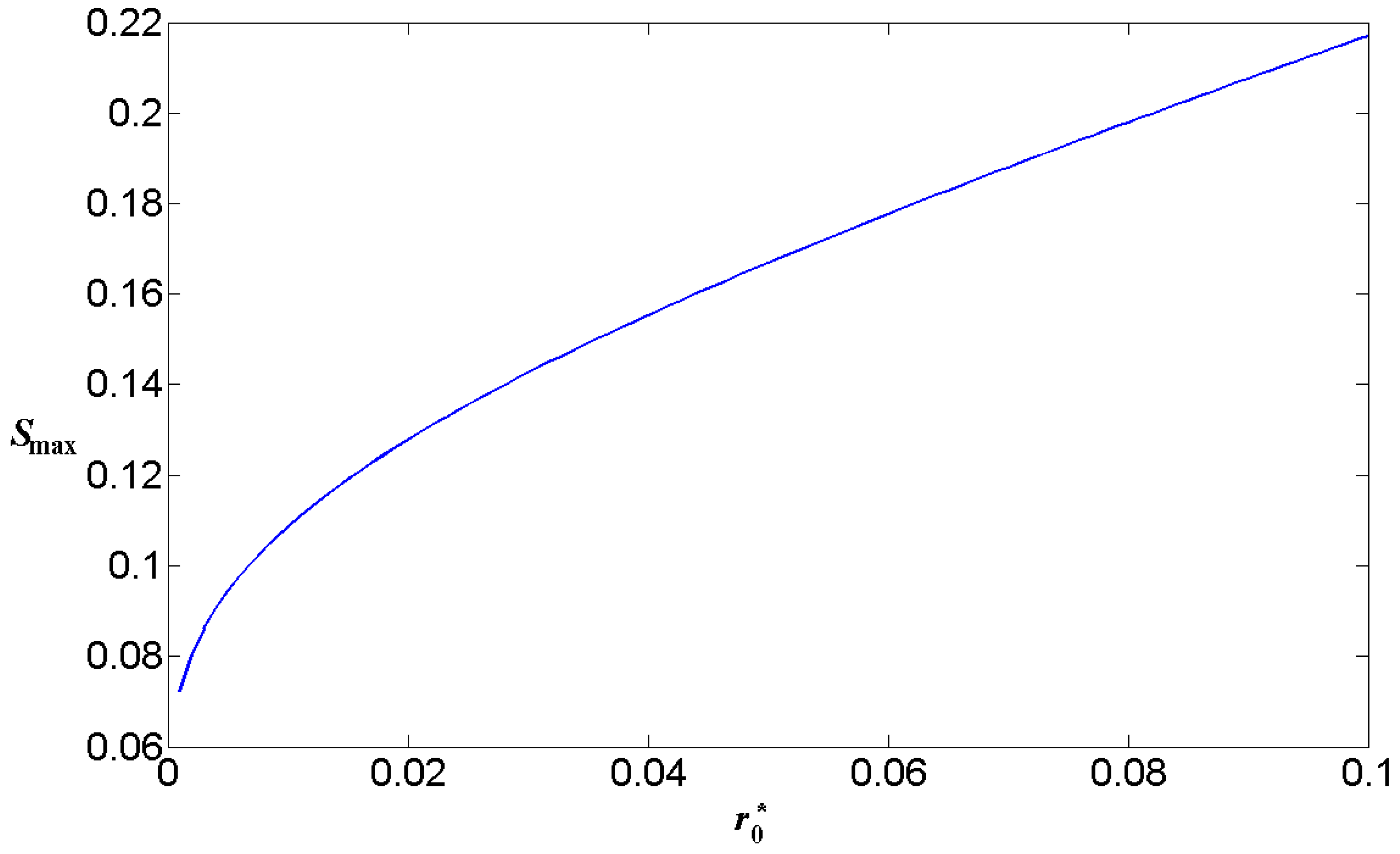
The situation of hydrostatic thrust bearings with no recess is much simpler, and the threshold value Smax is only affected by the radius of supply hole . In Figure 10, the relationship between the radius of supply hole and the threshold value Smax is displayed. It is found that the threshold value Smax is larger for the bearing with a larger radius of supply hole. When the radius is less than 0.04, with the increase of the radius , the gradient of threshold value Smax with respect to the radius decreases. When the radius is larger than 0.04, the gradient of threshold value Smax with respect to the radius is almost unchanged. Moreover, the threshold value Smax of hydrostatic thrust bearings with no recess is quite small in comparison to the situation of hydrostatic thrust bearings with circular recess.
Figure 10.
The threshold value of the inertial parameter for the hydrostatic thrust bearing with no recess.
5. Conclusions
With pressure distribution of two kinds of hydrostatic thrust bearings (circular recess and no recess), the threshold conditions to avoid cavitation are expressed with the structure parameters and inertial parameter of bearings. Based on the discussions above, following conclusions could be obtained:
- (1)
- For the hydrostatic thrust bearing with recess radius larger than 0.607, the cavitation of oil film could be avoided by chosen an appropriate value of film thickness ratio β, and the larger value of recess radius is matched with a shallower recess. At this situation, no matter how high the rotation speed of bearings is, the cavitation of oil film would not happen.
- (2)
- If the recess radius of hydrostatic thrust bearings is less than 0.607, there is a threshold value Smax for the inertial parameter of bearings. When the bearing with larger values of recess radius and film thickness ratio β, the threshold value Smax would be larger, too. Thus, to improve the threshold speed of bearings, recess radius and film thickness ratio β of the bearing should be chosen larger values.
- (3)
- For the hydrostatic thrust bearing with no recess, the threshold value Smax of bearings is completely determined by the radius of supply hole , and the relation between them is positively related. The threshold value Smax of bearings with no recess is quite smaller than that of bearings with circular recess.
- (4)
- The results of this study are only suitable for hydrostatic thrust bearings with circular recess or no recess. For the hydrostatic thrust bearing with annular recess or hydrostatic journal bearings, the results in this study cannot be applied.
Author Contributions
Methodology, Z.T.; formal analysis, C.L.; investigation, H.L. (Huaiqing Lu); writing—original draft preparation, Z.T.; writing—review and editing, H.L. (Haibo Liang). All authors have read and agreed to the published version of the manuscript.
Funding
This research is supported by National Key Research and Development Program of China (No. 2020YFB2007600).
Data Availability Statement
Data are contained within the article.
Conflicts of Interest
Authors Chunlin Li, Haibo Liang were employed by HXF SAW Co., Ltd. The remaining authors declare that the research was conducted in the absence of any commercial or financial relationships that could be construed as a potential conflict of interest.
Nomenclature
| Nomenclature | Greek symbols | ||
| β | film thickness ratio | ||
| h | film thickness | ρ | fluid density |
| Ps | supply pressure | ω | angular velocity of runner |
| p | film pressure | μ | viscosity of lubricant |
| p0 | film pressure in region of supply hole | Dimensionless parameters | |
| p1 | film pressure in region of recess | ||
| p2 | film pressure in region of bearing land | p* | p/Ps |
| Q | radial flow rate of fluid | p0/Ps | |
| R | radius of bearing | p1/Ps | |
| r | radial coordinate | p2/Ps | |
| r0 | radius of supply hole | Q* | 6μQ/(πh3Ps) |
| r1 | recess radius | r* | r/R |
| u | radial velocity of fluid | r0/R | |
| v | circumferential velocity of fluid | r1/R | |
| z | vertical coordinate | S | 3ρR2ω2/(20 Ps) |
| W | load capacity of fluid | W* | W/(πR2 Ps) |
References
- Yu, X.; Gao, W.; Feng, Y.; Shi, G.; Li, S.; Chen, M.; Zhang, R.; Wang, J.; Jia, W.; Jiao, J.; et al. Research progress of hydrostatic bearing and hydrostatic-hydrodynamic hybrid bearing in high-end computer numerical control machine equipment. Int. J. Precis. Eng. Manuf. 2023, 24, 1053–1081. [Google Scholar] [CrossRef] [Scilit]
- Yu, X.; Shao, M.; Yang, X.; Lin, Y.; Lan, Z.; Li, L.; Li, E.; Dai, R.; Jia, W.; Wang, J.; et al. Advances in the investigation of thermal characteristics of hydrostatic bearing spindle: An overview. J. Therm. Anal. Calorim. 2025, 150, 3139–3171. [Google Scholar] [CrossRef] [Scilit]
- Yang, X.; Liu, W.; Liu, H.; Liu, H.; Zeng, L. A review of hydrostatic bearing: Research and analysis. Recent Pat. Eng. 2022, 16, 1–11. [Google Scholar]
- Yi, H.; Jung, H.; Kim, K.; Ryu, K. Static load characteristics of hydrostatic journal bearings: Measurements and predictions. Sensors 2022, 22, 7466. [Google Scholar] [CrossRef] [Scilit] [PubMed]
- Jung, H.; Kim, K.; Ryu, K. On the performance of hydrostatic journal bearings in air, water, and liquid nitrogen: Measurements and predictions. J. Eng. Gas Turbines Power 2023, 145, 111011. [Google Scholar] [CrossRef] [Scilit]
- Lim, H.; Ryu, K. Experimental force coefficients of a hydrostatic thrust bearing and comparisons to predictions. J. Eng. Gas Turbines Power 2023, 145, 111010. [Google Scholar] [CrossRef] [Scilit]
- Yu, X.; Tang, B.; Wang, S.; Han, Z.; Li, S.; Chen, M.; Zhang, R.; Wang, J.; Jiao, J.; Jiang, H. High-speed and heavy-load tribological properties of hydrostatic thrust bearing with double rectangular recess. Int. J. Hydrogen Energy 2022, 47, 21273–21286. [Google Scholar]
- Dowson, D. Inertia effects in hydrostatic thrust bearings. J. Fluids Eng. 1961, 83, 227–234. [Google Scholar] [CrossRef] [Scilit]
- Bakker, O.J.; Ostayen, R.A.J.V. Recess depth optimization for rotating, annular, and circular recess hydrostatic thrust bearings. J. Tribol. 2010, 132, 011103. [Google Scholar]
- Singh, U.P.; Gupta, R.S.; Kapur, V.K. On the steady performance of hydrostatic thrust bearing: Rabinowitsch fluid model. Tribol. Trans. 2011, 54, 723–729. [Google Scholar] [CrossRef] [Scilit]
- Huang, Y.; Tian, Z. A new derivation to study the steady performance of hydrostatic thrust bearing: Rabinowitch fluid model. J. Non-Newton. Fluid Mech. 2017, 246, 31–35. [Google Scholar] [CrossRef] [Scilit]
- Lin, J.R. Static and dynamic characteristics of externally pressurized circular step thrust bearings lubricated with couple stress fluids. Tribol. Int. 1999, 32, 207–216. [Google Scholar] [CrossRef] [Scilit]
- Shukla, S.; Deheri, G. Magnetic fluid lubrication of rough thrust bearings considering a sine film profile. Proc. Jangjeon Math. Soc. 2019, 22, 151–162. [Google Scholar]
- Lu, H.; Tian, Z. Investigation of the static performance of hydrostatic thrust bearings considering non-Gaussian surface topography. Lubricants 2023, 11, 267. [Google Scholar] [CrossRef] [Scilit]
- Walicka, A.; Walicki, E.; Jurczak, P.; Falicki, J. Curvilinear squeeze film bearing with rough surfaces lubricated by a Rabinowitsch–Rotem–Shinnar fluid. Appl. Math. Model. 2016, 40, 7916–7927. [Google Scholar] [CrossRef] [Scilit]
- Singh, U.P. Mathematical analysis of effects of surface roughness on steady performance of hydrostatic thrust bearings lubricated with Rabinowitsch type fluids. J. Appl. Fluid Mech. 2020, 13, 1339–1347. [Google Scholar] [CrossRef] [Scilit]
- Osterle, J.F.; Hughes, W.F. Inertia-induced cavitation in hydrostatic thrust bearings. Wear 1961, 4, 228–233. [Google Scholar] [CrossRef] [Scilit]
- Wang, L.; Jiang, S. Centrifugal effects on the dynamic characteristics of high speed hydrostatic thrust bearing lubricated by low viscosity fluid. Proc. Inst. Mech. Eng. Part J J. Eng. Tribol. 2014, 228, 860–871. [Google Scholar] [CrossRef] [Scilit]
- Coombs, J.A.; Dowson, D. An Experimental Investigation of the Effects of Lubricant Inertia in a Hydrostatic Thrust Bearing. In Proceedings of the Institution of Mechanical Engineers, Conference Proceedings; SAGE Publications: London, UK, 1964; Volume 179, pp. 96–114. [Google Scholar]
- Kamat, H.; Kini, C.R.; Shenoy, S.B. Effect of cavitation and temperature on fluid film bearing using CFD and FSI technique: A review. Arch. Comput. Methods Eng. 2023, 30, 1623–1636. [Google Scholar] [CrossRef] [Scilit]
- Li, R.; Hou, L.; Zhou, G.; Hao, K.; Yang, R.; Zhou, Q. Mixed lubrication performance analysis of a novel water-lubricated thrust bearing considering transient thermal, cavitation, and turbulence. Phys. Fluids 2025, 37, 015126. [Google Scholar] [CrossRef] [Scilit]
- Feng, H.; Peng, L. Numerical analysis of water-lubricated thrust bearing with groove texture considering turbulence and cavitation. Ind. Lubr. Tribol. 2018, 70, 1127–1136. [Google Scholar] [CrossRef] [Scilit]
- Lin, X.; Wang, R.; Zhang, S.; Zhang, C.; Jiang, S. Study of cavitation bubbles evolution for high-speed water-lubricated spiral groove thrust bearings. J. Tribol. 2019, 141, 051703. [Google Scholar]
- Song, Y.; Ren, X.; Gu, C.; Li, X.-S. Experimental and numerical studies of cavitation effects in a tapered land thrust bearing. J. Tribol. 2015, 137, 011701. [Google Scholar]
- Lin, X.; Jiang, S.; Zhang, C.; Liu, X. Thermohydrodynamic analysis of high speed water-lubricated spiral groove thrust bearing considering effects of cavitation, inertia and turbulence. Tribol. Int. 2018, 119, 645–658. [Google Scholar] [CrossRef] [Scilit]
- Yan, S.; Zhao, Q.; Lai, T.; Hou, Y. Vibration characteristics analysis of liquid hydrogen lubricating herringbone spiral-grooved thrust bearing considering cavitation. Proc. Inst. Mech. Eng. Part C J. Mech. Eng. Sci. 2025, 239, 2899–2913. [Google Scholar]
- Kailei, L.; Jiayuan, C.; Haoran, Z.; Lin, Z.; Xuze, W.; Yu, C. Investigation of Geometric Characteristics on the Lubricant Performance of Thrust Bearing with Cavitation. J. Appl. Fluid Mech. 2025, 18, 1833–1842. [Google Scholar] [CrossRef] [Scilit]
- Chen, Y.; Shi, X.; Wang, X.; Lin, Z.; Xuze, W.; Yu, C. Multi-objective analysis design of spiral groove conical bearing considering cavitation effects. Results Eng. 2022, 15, 100582. [Google Scholar] [CrossRef] [Scilit]
- Zhang, S.; Jiang, S.; Lin, X. Static and dynamic characteristics of high-speed water-lubricated spiral-groove thrust bearing considering cavitating and centrifugal effects. Tribol. Int. 2020, 145, 106159. [Google Scholar]
- Zhang, J.; Meng, Y. Direct observation of cavitation phenomenon and hydrodynamic lubrication analysis of textured surfaces. Tribol. Lett. 2012, 46, 147–158. [Google Scholar] [CrossRef] [Scilit]
- Tian, Z.; Cao, H.; Huang, Y. Static characteristics of hydrostatic thrust bearing considering the inertia effect on the region of supply hole. Proc. Inst. Mech. Eng. Part J J. Eng. Tribol. 2019, 233, 188–193. [Google Scholar]
Disclaimer/Publisher’s Note: The statements, opinions and data contained in all publications are solely those of the individual author(s) and contributor(s) and not of MDPI and/or the editor(s). MDPI and/or the editor(s) disclaim responsibility for any injury to people or property resulting from any ideas, methods, instructions or products referred to in the content. |
© 2026 by the authors. Licensee MDPI, Basel, Switzerland. This article is an open access article distributed under the terms and conditions of the Creative Commons Attribution (CC BY) license.