


Abstract
The design and main parameters of a plasma–chemical reactor containing two compartments are presented. One compartment houses a vacuum-arc evaporator, while the other houses a planar magnetron. The compartments are separated by a diaphragm with a dosing slot for injecting copper vapor into the TiN synthesis compartment. The conditions for the synthesis of superhard TiN-Cu composite coatings are experimentally determined. Based on established process parameters for TiN synthesis in a nitrogen-containing plasma by Ti evaporation using a vacuum-arc discharge, it is proposed to apply TiN-Cu coatings by injecting Cu vapor into the TiN synthesis area and sputtering Cu using a magnetron discharge. XRD analyses of both TiN and TiN-Cu coatings show the presence of WC, Ti2C, and TiN. EDS analysis confirms 5.57 at. % copper on the surface of the TiN-Cu coating. Real-life operating tests of TiN-Cu coatings on replaceable WC-TiC-Co (79/15/6 wt.%) alloy hexagonal inserts used for cutting 40Kh steel revealed that applying the TiN-Cu coating extends the tool life of WC-TiC-Co inserts by about 2.5 times compared with uncoated tools. Cutting force measurements on TiN-Cu-coated inserts showed no vibration or noise during cutting, driven by a reduced friction coefficient and improved heat dissipation at the contact zone between the cutting edge and the workpiece, thereby lowering the temperature in that area.
1. Introduction
The development of a new class of materials with coatings that offer broad functional capabilities is a priority area of modern physical materials science. Nanocrystalline composite coatings, possessing unique physical and mechanical properties, significantly improve the surface characteristics of cutting tools, components, assemblies, and units of process equipment. The properties of such coatings can be enhanced by creating multiphase compositions [1,2,3].
One of the first nitride coatings used to improve the wear resistance of cutting tools was TiN, produced by evaporating metallic titanium in a nitrogen atmosphere [4]. Further advances in physical vapor deposition (PVD) technologies have facilitated the intensive development of new protective TiN-based composite coatings, among which the most widely studied are TiAlN, TiSiN, ZrN, CrN, CrAlN, AlCrSiN, and TiN-Cu [5,6,7].
Although binary coatings exhibit good functional characteristics, research has shown that multiphase and multilayer structures often demonstrate superior performance. Synthesizing such coatings enables targeted control of properties such as hardness, elasticity, wear resistance, and crack resistance, ensuring an optimal balance between mechanical and performance characteristics. The TiN-Cu composite coatings with a nanocrystalline structure discussed in this paper, synthesized by adding copper to TiN coatings, exhibit high hardness and ductility [8,9,10].
When Cu atoms are localized to form a layer along the boundaries of TiN crystallites, they inhibit the growth of the columnar structure, leading to nanostructuring of superhard TiN-Cu coatings with an average grain size of approximately 20 nm [11]. A common method for synthesizing TiN-Cu coatings involves evaporation of composite cathodes, sintered from Ti and Cu powders in an arc discharge [2,10]. In this process, the coatings are produced under conditions influenced by the gas-discharge nitrogen plasma of an auxiliary arc. However, using composite cathodes complicates the control of Cu addition.
Alternatively, Myung et al. [12] described the synthesis of TiNi–Cu films using a hybrid approach combining reactive cathodic arc ion plating of Ti with unbalanced magnetron sputtering of Cu in a nitrogen environment. This enables precise control of the crystallite size during coating growth, which is crucial because the nanostructure, microhardness, and crack resistance depend, to some extent, on the copper impurity concentration. Although this method has benefits, it also presents challenges, such as mutual interference between the arc and magnetron discharges. A circular Ti cathode for arc evaporation was placed on one side of the chamber, with the Cu magnetron source positioned on the opposite side. When these discharges face each other, they cause contamination from Ti and Cu vapors. In addition, the substrate 0° tilt to discharges notably diminishes the efficiency of TiNi–Cu film deposition.
The current research proposes a new approach to applying TiN-Cu composite coatings by dividing the vacuum chamber into two compartments using a diaphragm (separator plate) [13,14]. Firstly, the separating diaphragm prevents mutual influence between different discharges, such as vacuum arc and magnetron discharges. Such an approach prevents the Co cathode magnetron from being contaminated by Ti vapor, and vice versa. Cu vapor enters through a diaphragm dosing hole into the compartment where the chemical reaction between Ti and N occurs.
In this paper, a plasma–chemical reactor based on reconstructing a typical VU-1B vacuum installation by placing a planar magnetron in the vacuum chamber is considered [13,15]. Unlike [12], the vacuum chamber is divided by a diaphragm into two compartments: the first for TiN synthesis and the second for Cu vaporization. The synthesis of TiN-Cu nanocomposite coatings, which combine Ti vacuum-arc evaporation and Cu magnetron sputtering [13,14,15,16], is studied on replaceable hexagonal plates made of T15K6 hard alloys. The phase and elemental composition, microstructure, and tribological properties of the coatings, including their resistance to cutting low-alloy 40Kh steel, are considered.
2. Materials and Methods
For the current research, T15K6, a high-performance tungsten–titanium–cobalt sintered hard alloy classified as ISO P20, was used as the substrate material. Its nominal chemical composition consists of 79 wt.% WC, 15 wt.% TiC, and a 6 wt.% Co binder. Microhardness ranges from 15.5 to 16.5 GPa. It is mainly used for semi-rough turning and milling of carbon and alloy steels at high cutting speeds.
2.1. The Plasma–Chemical Reactor for the Synthesis of TiN-Cu Composite Coatings
The TiN-Cu composite coatings were synthesized inside a vacuum chamber with a plasma–chemical reactor [14,15]. The functional diagram of the plasma–chemical reactor is shown in Figure 1. Vacuum-arc evaporator 3 is installed on the upper horizontal wall of compartment 1, while planar magnetron 4 is vertically mounted on the side wall of compartment 2. The evaporator features a cooled, welded housing with cathode 5, anode 6, igniter 7, and solenoid 8, which produces a magnetic field of about 10 mT. The cathode, 60 mm in diameter and made of VT-1-0 titanium, is water-cooled. Its power supply delivers approximately 4 kW. The magnetron uses copper cathode 9, which has a diameter of 50–120 mm and a thickness of 12 mm, along with the ring-shaped anode 10. Magnetic system 11, composed of permanent cobalt–samarium rods, a magnetic core, and a pole piece, creates a toroidal magnetic field with an induction of 0.2–0.8 T over the target surface. This magnetic field confines the plasma above the cathode. Water cooling maintains the stable operation of the magnets, and the magnetron’s power supply is about 1 kW. The discharge control unit adjusts the power and sputtering rate of copper cathode 9.
Figure 1.
Functional diagram of the plasma–chemical reactor [13].
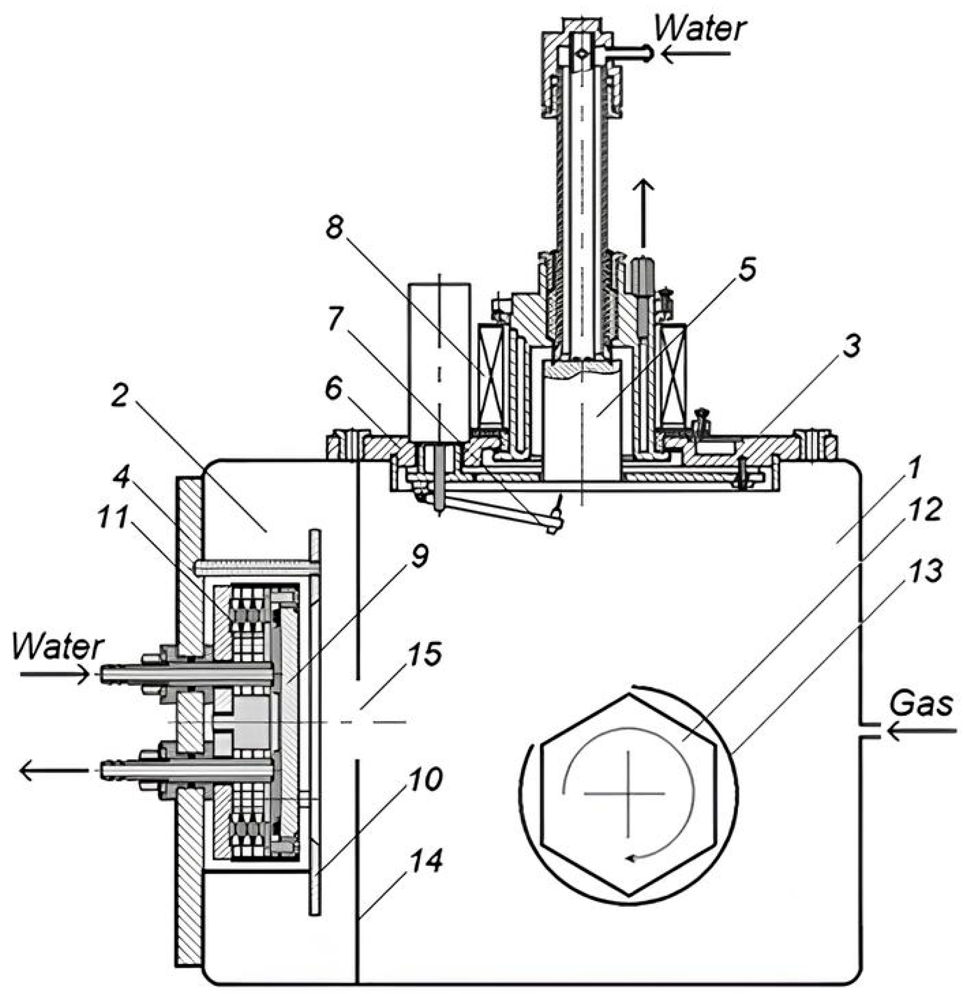
Compartment 1 of the vacuum chamber contains drum-type substrate holder 12. The substrates consist of replaceable hexagonal inserts of type 11114 (HNUM), according to GOST 19068-80 [17], fabricated from T15K6 hard alloys and commonly used for through-cutting cutters and end mills. During TiN/TiN-Cu coating growth, the surface of the initial substrates is angled at 45° relative to the normals of the orthogonal planes of the evaporated titanium and sputtered copper cathodes. The reserve substrates are shielded by a screen 13. Upon cessation of coating growth, the substrate holder is rotated to 60°, and the subsequent substrates are removed from the screen, thereby exposing the growth surface for coating. The distance from the magnetron cathode to the substrates ranges from 120 to 140 mm. A bias voltage of 160–180 V applied to the substrate holder facilitates the deposition of TiN-Cu coatings in the ion-assisted mode. Compartments 1 (for TiN synthesis) and 2 (for Cu vaporization) are separated by diaphragm 14. This diaphragm primarily prevents mutual influence between the vacuum arc and magnetron discharge modes, ensuring their stable, steady-state operation, and it also prevents titanium vapor from reaching copper cathode 9 of the magnetron. Additionally, dosing slot 15 (measuring 5 × 100 mm2) in diaphragm 14 allows Cu vapor to penetrate from compartment 1 onto the substrate, where a chemical reaction occurs between titanium and nitrogen in the Cu vapor. The plasma–chemical reactor is evacuated to a residual pressure of 6.6 × 10⁻³ Pa using an H400 diffusion pump (Agilent Technologies, Santa Clara, USA). Preliminary vacuum is provided by the AVZ-20D fore vacuum pump (Valdai Pumping Plant, Valdai, Russia).
2.2. The Approaches for Surface Investigation, Physical, and Chemical Properties of TiN-Cu Composite Coatings
X-ray diffraction (XRD) analysis of the coatings was conducted on a D2 Phaser (Bruker AXS GmbH, Karlsruhe, Germany) diffractometer utilizing a LYNXEYE linear powder diffraction detector, and the XRD data were interpreted using the DIFFRAC.EVA software package Version 3.0 with the international ICDD PDF2 database. X-ray spectral microanalysis (EDS) of the coating structure was performed using a JSM-6510LV (JEOL Ltd., Tokyo, Japan) scanning electron microscope equipped with an INCA Energy 350 microanalysis system (Oxford Instruments, Abingdon, UK). The surface structure of the TiN-Cu composite coating was analyzed metallographically using a METAM RV-21 (LOMO, Saint Petersburg, Russia) optical microscope, which was equipped with a VEC-335 digital camera and NEXSYS ImageExpert Pro 3.0 software package. A MultiMode8 scanning atomic force microscope (AFM) (Bruker AXS GmbH, Karlsruhe, Germany) was used to characterize the coating’s topography and surface structure in close-contact mode within an area of 25 μm × 25 μm. The microhardness of the formed layers was measured using a PMT-3 M (LOMO, Saint Petersburg, Russia) microhardness tester, which features a digital camera and NEXSYS ImageExpert MicroHardness 2 software for processing indentation images, following the GOST 9450-76 standard for the Knoop indentation reconstruction method [18]. The Knoop hardness was measured at a load of 1.96 N, with a dwell time of 15 s.
2.3. The Real-Life Operating Testing Conditions and Facility
Testing of the TiN-Cu coatings under real-life operating conditions under critical loads was conducted using T15K6 hexagonal indexable inserts mounted on the cutting tool of a UDM-600 dynamometer while cutting 40Kh steel on a 16K20 lathe. The machining experiments were conducted using a universal 16K20 screw-cutting lathe (Krasny Proletariy Machine Tool Plant, Moscow, Russia). This high-precision industrial lathe features a 400 mm swing over the bed and an 11 kW spindle power, providing the mechanical stability required for high-speed cutting tests. Digital images obtained using a METAM PB-34 (LOMO, Saint Petersburg, Russia) optical microscope and an Altami Studio camera were used to plot wear contours and assess wear on the rear surface of the T15K6 inserts.
Cutting force tests were conducted using a UDM-600 dynamometer-sensor designed by VNII [18], in conjunction with a specialized measuring transducer and the LTR-U-1 modular data acquisition system, with data registration and recording on a personal computer using PowerGraph Professional software Version 3.3. The workpiece was a 50 mm diameter rod made of 40Kh steel (analogous to AISI 5135 or AISI 5140). Longitudinal turning was performed using a cutter with hexagonal replaceable inserts made of T15K6 hard alloy, according to GOST 19047-80 [19], with previously applied TiN-Cu coatings under the following conditions: cutting speed of 150 m/min, feed rate of 0.5 mm/rev, and cutting depth of 2.0 mm. The cutting parameters used to test the coating durability were selected as standard or characteristic machining conditions for steel 40Kh, which served as the workpiece in our research. Cutting conditions were selected based on the upper temperature resistance limit of the T15K6 alloy, which is 900–1000 °C. The cutting speed was optimized to keep the average temperature in the tool–workpiece contact zone below critical values, thereby maintaining cutting-edge stability and preventing intense diffusion wear. At least 5 repetitions on the machining tests were conducted for each coated and uncoated sample.
3. Results
3.1. Selection of Parameters of a Plasma–Chemical Reactor for the Synthesis of TiN-Cu Composite Coatings
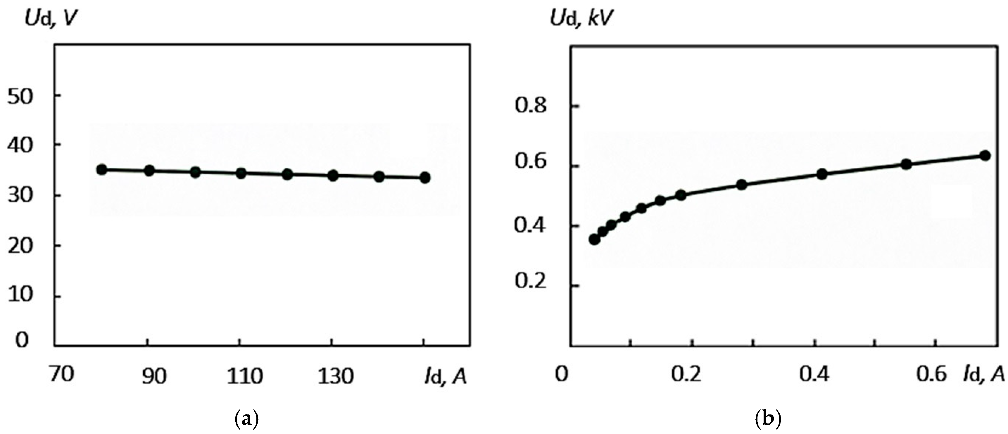
A gas mixture comprising 80% N2 and 20% Ar is introduced into compartments 1 and 2 of the plasma–chemical reactor via a needle leak valve. Upon application of voltage from the power supply between cathode 5 and anode 3, a vacuum arc discharge characterized by a cathode spot is initiated in compartment 1 through igniting electrode 7. The magnetic field generated by solenoid 8 ensures the uniform evaporation of the titanium cathode by the arc discharge’s cathode spot. The arc discharge parameters are as follows: arc current (Id) ranges from 60 to 150 A; the nitrogen working gas pressure ranges from 2.6 × 10⁻¹ to 12 Pa; the arc voltage (Ud) varies between 30 and 40 V, as illustrated in Figure 2a.
Figure 2.
Volt-ampere characteristics: (a)—vacuum arc discharge (pressure 0.6 Pa, titanium cathode); (b)—magnetron discharge (pressure 3.0 × 10⁻¹ Pa, copper cathode).
During the evaporation of titanium and the dissociation of molecular nitrogen (N2 ↔ 2N) in the nitrogen-containing plasma, a chemical reaction occurs on the surface of screen 13, where Ti reacts with reactive atomic N on the substrate, forming TiN. As the vacuum arc evaporator enters the steady-state arc discharge mode, when a direct electric voltage of up to 1.6 kV is applied to the grounded anode 10 (positive polarity) and the insulated cathode 9 (negative polarity), a magnetron discharge is initiated in compartment 2. The discharge current remained below 1 A and was controlled by the power source. Figure 2b illustrates the typical current–voltage characteristic observed in a direct current discharge within the argon pressure range of ~ (3.0–6.6) × 10–1 Pa for stable ignition and sustained discharge.
As the nitrogen gas pressure increased beyond the aforementioned range for stable magnetron operation, the discharge voltage decreased slightly. This was observed due to the steepness of the Id(Ud) curves (Figure 2b). The discharge current rose markedly as pressure increased, using a copper target at the same discharge conditions voltage. The discharge voltage in the experiments ranged from 400 to 500 V and depended on the nitrogen–argon gas mixture pressure.
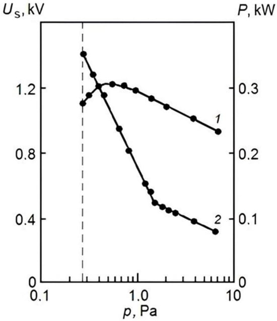
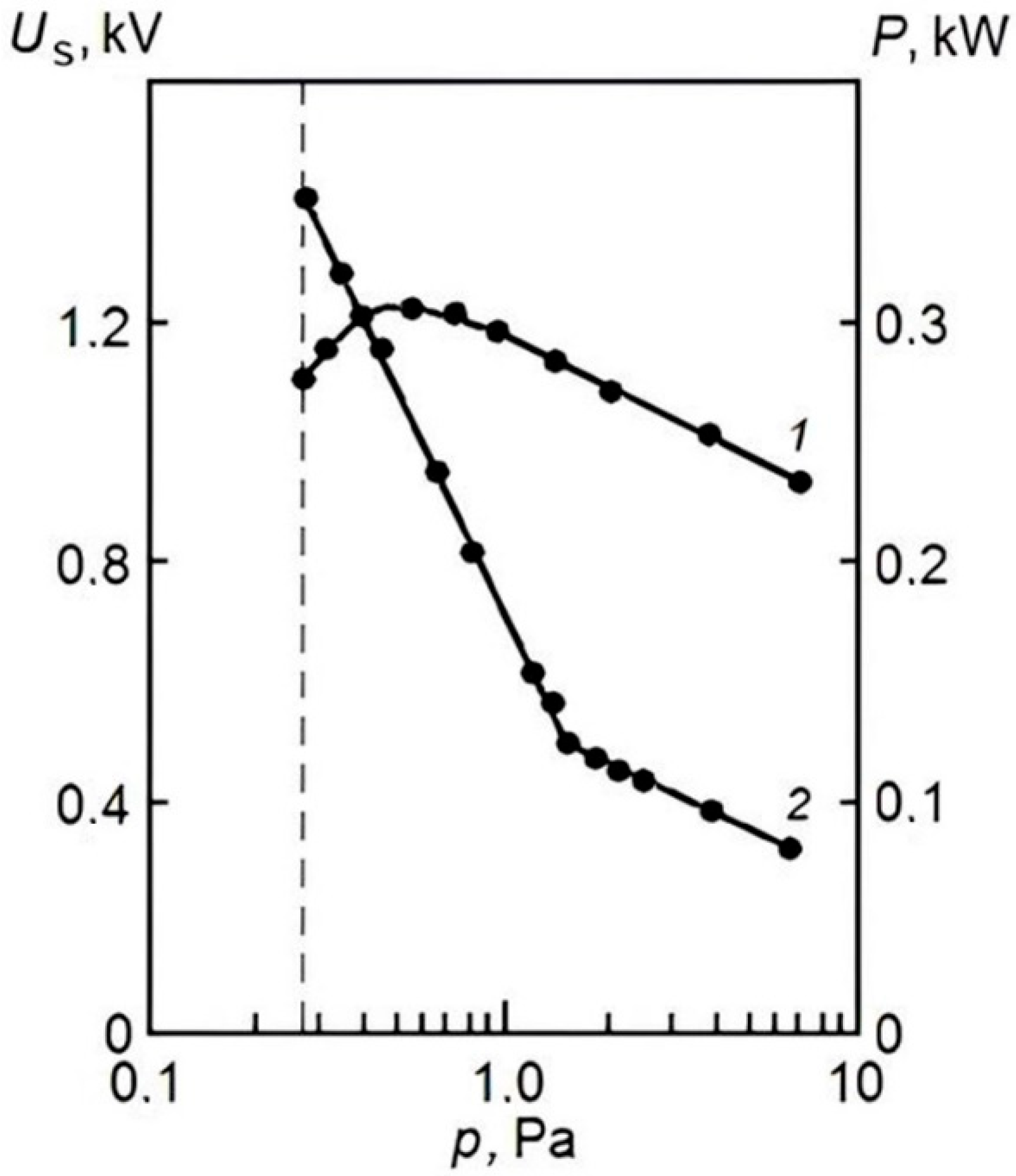
The principal operational parameters of the magnetron include the electrode voltage, discharge current, ion current density on the target, discharge power, the radial component of magnetic induction, and gas pressure [20,21,22,23]. The growth rate of the coatings is linearly related to the discharge power. As demonstrated in curve 1 of Figure 3, the dependence of the discharge power P on the gas pressure p at a constant power output of the power source reveals that, as gas pressure diminishes, the discharge power correspondingly increases. At approximately 4.5 × 10⁻¹ Pa, the nature of this dependence shifts from an increasing to a decreasing trend. The emergence of a maximum in the P(p) dependence signifies the presence of a specific gas pressure at which maximum power is delivered during the discharge process. Furthermore, a critical pressure near 1.5 Pa exists, below which a pronounced dependence of the ignition voltage Us on the pressure p is observed, as illustrated by curve 2 in Figure 3. It is apparent that, as pressure decreases below this critical threshold, the ignition voltage rapidly escalates to the nominal rectified voltage supplied by the power source, beyond which the discharge fails to ignite. For gas pressures above the critical level, the ignition voltage varies little with pressure, whereas gas-gap breakdown occurs at comparatively low voltages.
Figure 3.
Dependencies of magnetron discharge power (1) and ignition voltage (2) on gas pressure.
Due to plasma ions accelerated by the cathode potential drop physically sputtering the copper cathode, copper vapor passes through slot 15 in diaphragm 14 and deposits on screen 13. As the planar magnetron is brought into the mode of stable, stationary magnetron discharge, by rotating screen 13, access is opened (as shown in Figure 1) for titanium and copper vapors and reactive atomic nitrogen to the growth surface of the substrates, where the synthesis of TiN in copper vapor occurs with the formation of a TiN-Cu composite coating.
3.2. Surface Characterization and Composition of the Coatings
First, the TiN coating synthesis mode was tested using a vacuum arc evaporator in the absence of copper vapor (the planar magnetron was turned off). The substrates’ growth surfaces were pre-cleaned by glow discharge at ~1 kV in a vacuum of 6.8 Pa for 5 min. Next, the TiN coating process began. The main parameters were arc discharge current of 90 A, nitrogen gas pressure in the vacuum chamber of 0.37 Pa, synthesis time of 10 min, bias voltage of 160 V, and cathode-to-substrate distance of 230 mm.
The surface microstructure and elemental composition were examined using SEM and EDS. The coating surface is quite uniform and free of microdroplets due to the optimal vacuum arc discharge current settings (Figure 4a). It exhibits a dense, pore-free structure with clearly visible grain boundaries. The elemental composition in at. % is dominated by tungsten (W) at 54.57% and titanium (Ti) at 34.66%, reflecting the base alloy WC-TiC-Co with a TiN surface coating (Table 1). The nitrogen content (4.20%) confirms the formation of titanium nitride, while the presence of oxygen (2.65%) and cobalt (3.92%) indicates minor oxidation and binder participation in the surface layer.
Table 1.
Elemental composition (at.%) of the TiN and TiN-Cu coatings.
Figure 4.
SEM photographs of the coating surface: (a)—TiN; (b)—TiN-Cu. Adapted from [24].
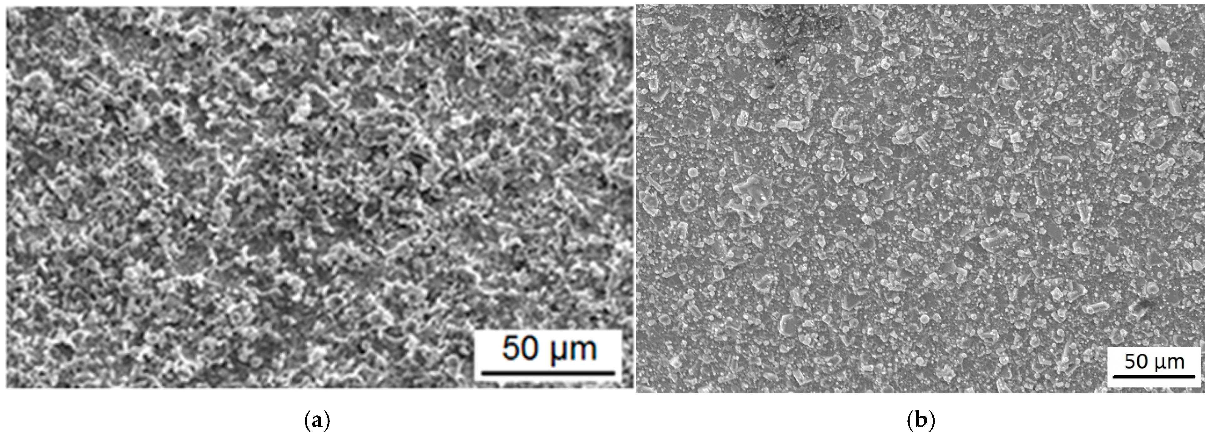
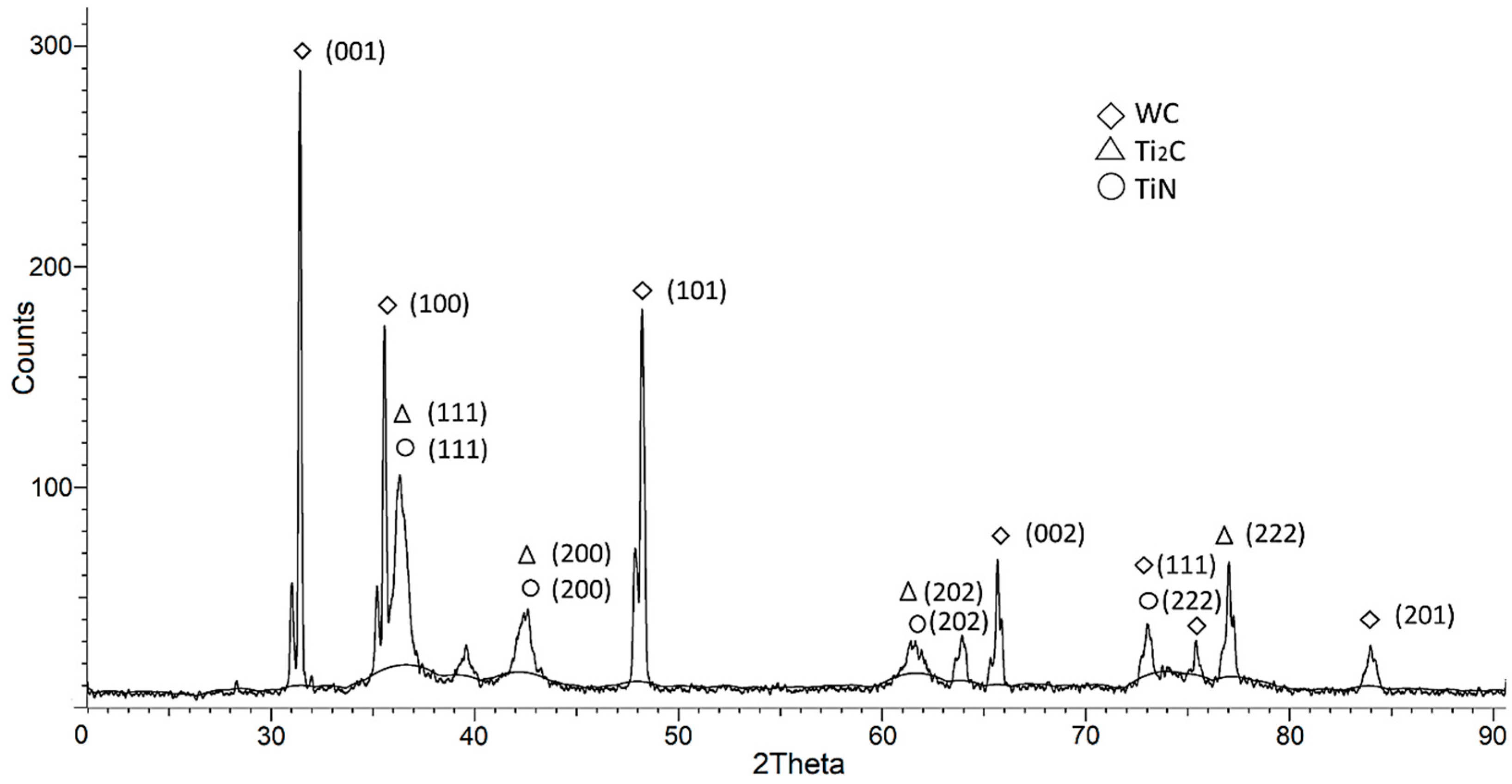
Figure 5 shows the XRD pattern of the TiN coating applied to the surface of the T15K6 alloy. According to the XRD analysis, along with the diffraction peaks of WC (001), (100), (101), (110), (002), (111), (200), (102), and (201) and Ti2C (111), (200), (202), (311), and (222) belonging to the T15K6 alloy, diffraction peaks of the TiN coating are observed. The crystallites of the TiN coating, which usually have a columnar structure, are partially textured along the (111) plane, although diffraction peaks belonging to other planes, (200), (202), and (222), with intensities that are not characteristic of them, can be distinguished. The microhardness of the TiN coating is 19 GPa.
Figure 5.
XRD pattern of TiN coating.
After testing the TiN coating synthesis modes, TiN (Figure 1) was synthesized in Cu vapor within the vacuum chamber of a plasma–chemical reactor [14,15], forming a TiN-Cu composite coating. To ensure more efficient sputtering of the magnetron’s copper cathode, N2 (80%) and Ar (20%) were mixed in a gas mixer to a total working-gas volume. The technological parameters for TiN-Cu coating deposition are as follows: The surface of the hard alloy is initially cleaned, activated, and heated to approximately 473 K, using metal-containing ions and plasma-forming gas ions for approximately 10 min. During this process, the bias voltage is set to 160 V, the arc discharge current to 90 A, the magnetron discharge current to 0.5 A, and the discharge voltage to 400 V. The gas-mixture pressure in the vacuum chamber is maintained at 2.4 Pa. The surface temperature of the T15K6 hard alloy is measured using a chromel–alumel thermocouple. Subsequently, in accordance with the synthesis technological parameters, the surface temperature of the hard alloy is maintained at approximately 473 K, and the TiN-Cu coating is synthesized for 15 min. The coating thickness was determined by a cross-section and is ~6 μm.
Figure 4b illustrates the surface microstructure of TiN-Cu composite coatings. The layer is uniform, featuring clear grain boundaries, with an average grain size of 10–15 µm.
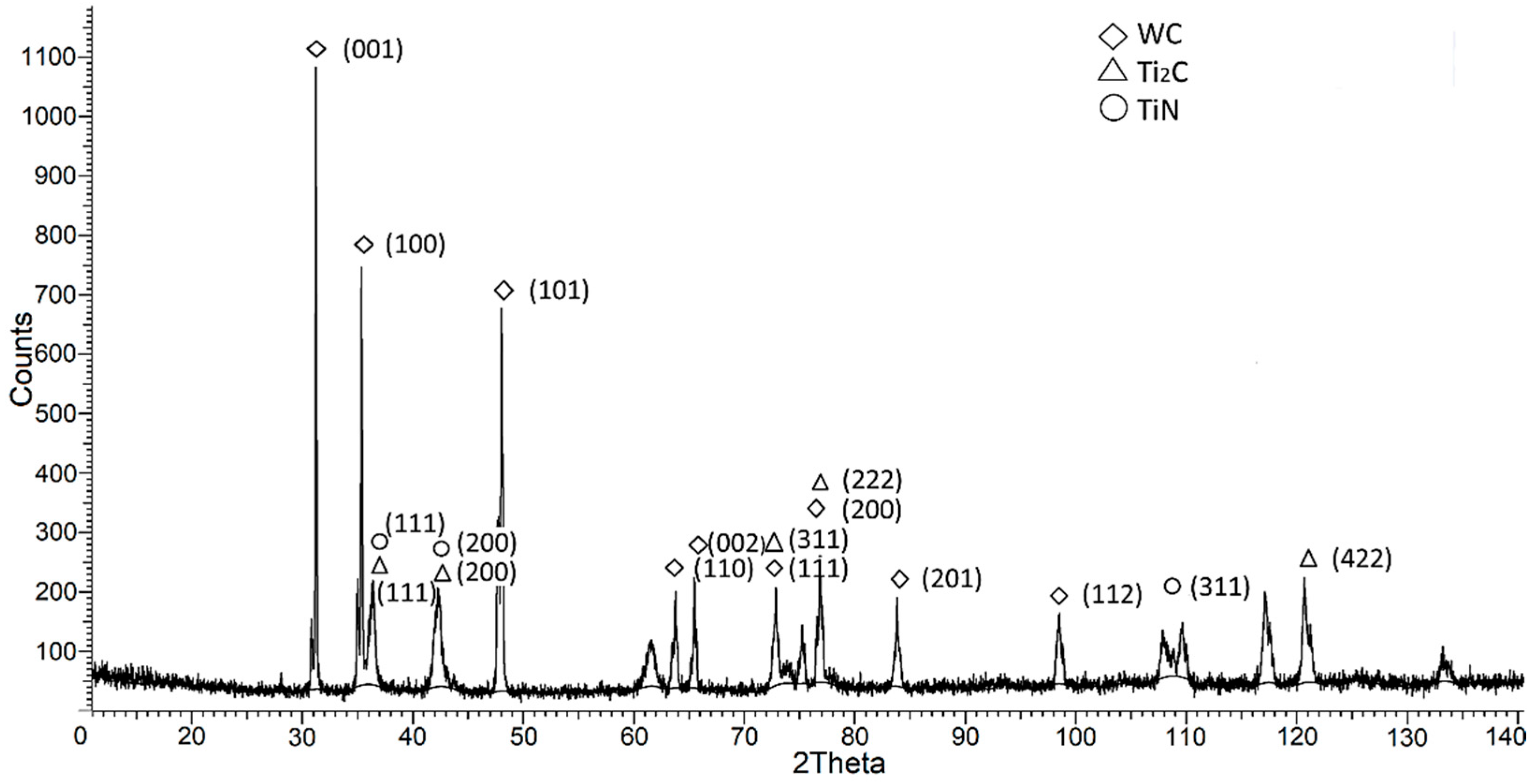
Figure 6 shows the XRD pattern of the TiN-Cu coating applied to the surface of the T15K6 alloy. According to the XRD analysis [13], along with the diffraction peaks of Ti2C (111), (200), (202), (311), (222), and (422) and WC (001), (100), (101), (110), (002), (111), (200), (201), and (112) belonging to the T15K6 alloy, the diffraction peaks of the TiN coating, namely (111), (200), (202), (222), and (311), with varying crystal lattices and volume fractions, are observed. No copper diffraction peaks are observed in the composite layer. At the same time, EDS analysis of the coatings confirms the presence of copper throughout the coating profile (Table 1). The elemental analysis, dominated by titanium (79.81%) and nitrogen (8.91%), confirms the formation of a TiN-Cu composite coating on the WC-TiC-Co substrate. The presence of copper (5.57%) and tungsten (5.48%) indicates successful alloying of the surface layer and partial diffusion from the hard alloy base, while the low oxygen content (0.23%) reflects the high phase purity of the deposition process.
Figure 6.
XRD pattern of TiN-Cu coating.
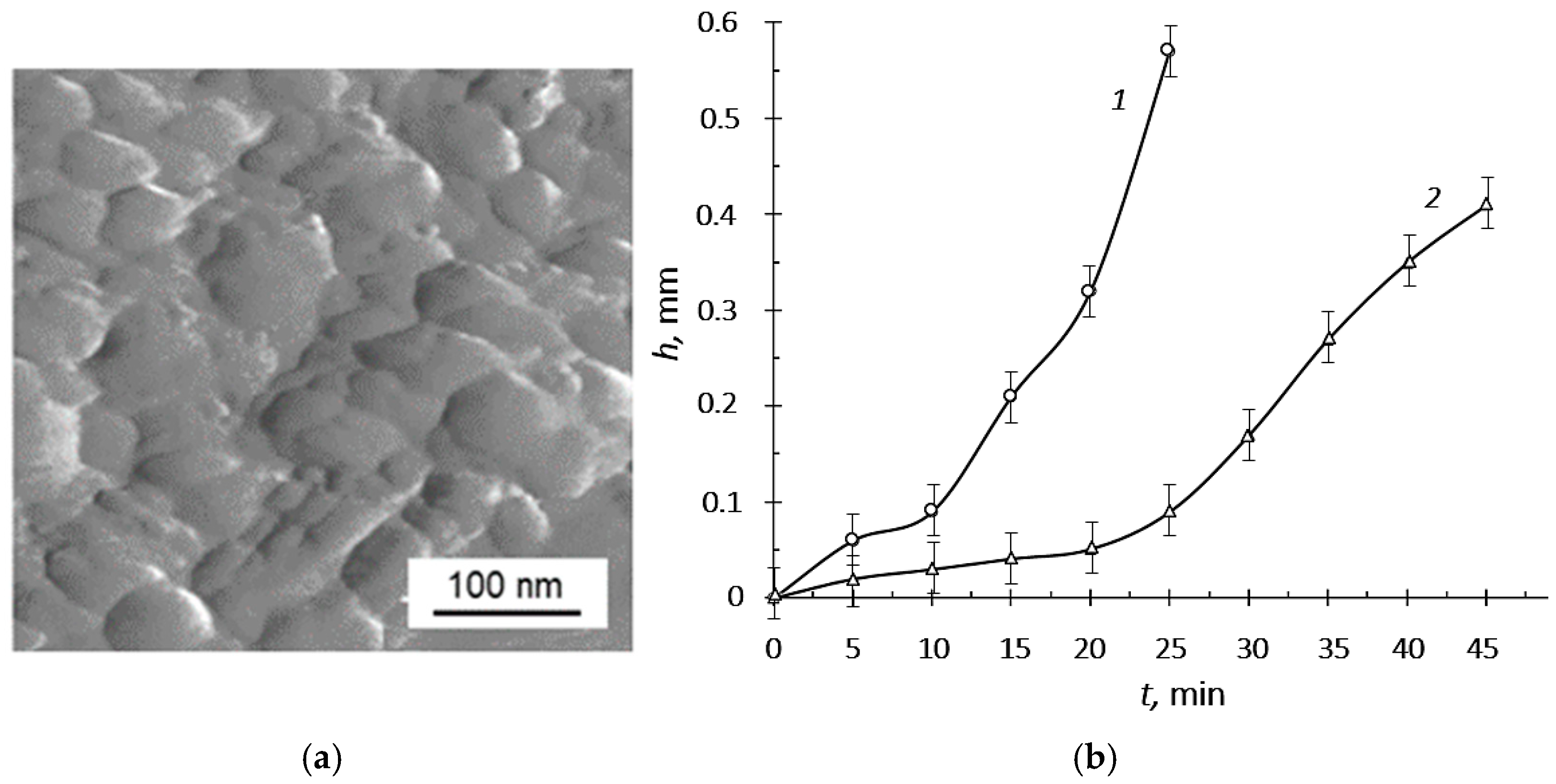
Copper, which does not form its own crystalline phase nor integrate into the crystal lattice of other phases, is situated at the boundaries of crystallites in an amorphous or X-ray-amorphous state. As indicated in references [10,12,25], during the reaction of Ti and N in Cu vapor, Cu is displaced to the intergranular boundary between titanium nitride (TiN) grains. Copper acts as an inhibitor to the growth of the columnar structure of TiN crystallites, thereby promoting the nanostructuring of TiN-Cu composite coatings. This phenomenon is supported, on one hand, by the low affinity of copper for nitrogen, as nitrogen does not form compounds with copper (copper does not directly combine with nitrogen; nitrogen nitride Cu3N cannot be synthesized). On the other hand, the phase diagram of the Ti-Cu system, as shown in references [26,27,28], indicates that at low copper atomic percentages, intermetallic compounds are not stable. However, at higher copper atomic percentages and temperatures between 1073 K and 1173 K, intermetallic compounds such as TiCu, Ti2Cu, Ti2Cu3, and TiCu3 form. Incorporating copper into the coating composition refines the nitride-phase crystallites to approximately 50 nm, as detailed in reference [15]. The duration during which copper atoms form a closed shell around a growing TiN crystallite governs the growth period of nanoscale TiN crystallites and consequently influences the crystallite size. Figure 7a displays the surface structure of the TiN–Cu composite coating, examined via MultiMode8 scanning atomic force microscopy, revealing a uniform globular structure with crystallite sizes ranging from 50 to 100 nm. The microhardness of these coatings is measured at 38–42 GPa.
Figure 7.
Structure of the TiN-Cu coating surface (a) and the wear values of T15K6 plates (b): 1—without coating; 2—with TiN-Cu coating. Adapted from [24].
3.3. Real-Life Operating Testing of TiN-Cu Coatings on the T15K6 Hard Alloy
Testing of TiN-Cu coatings demonstrated that the coatings did not undergo destruction (such as chipping or peeling) within the contact area of the cutting tool, thereby clearly indicating the high adhesion of the TiN-Cu coating to the T15K6 hard alloy, which was applied utilizing hybrid plasma technology.
The critical wear value on the flank surface for the coated T15K5 insert was taken as ~0.3 mm, and for the uncoated insert, ~0.5 mm. The wear values are a function of the cutting time t for steel, measured in 5 min increments (Figure 7b). The conducted tool life tests on cutting 40Kh steel with hexagonal T15K6 indexable inserts with TiN-Cu coatings indicate that, in the proposed method of applying TiN-Cu coatings, with a Cu content of 5.57 at. %, the tool life of T15K6 inserts is approximately 2.5 times superior to uncoated tools (Figure 7a).
In the cutting process, three force components are distinguished [29] (Figure 8a): PX (axial component/feed force), PY (radial component), and PZ (principal/tangential component).
Figure 8.
Testing of TiN-Cu coatings: (a)—dynamometer UDM-600; (b)—cutting force components. Adapted from [24].
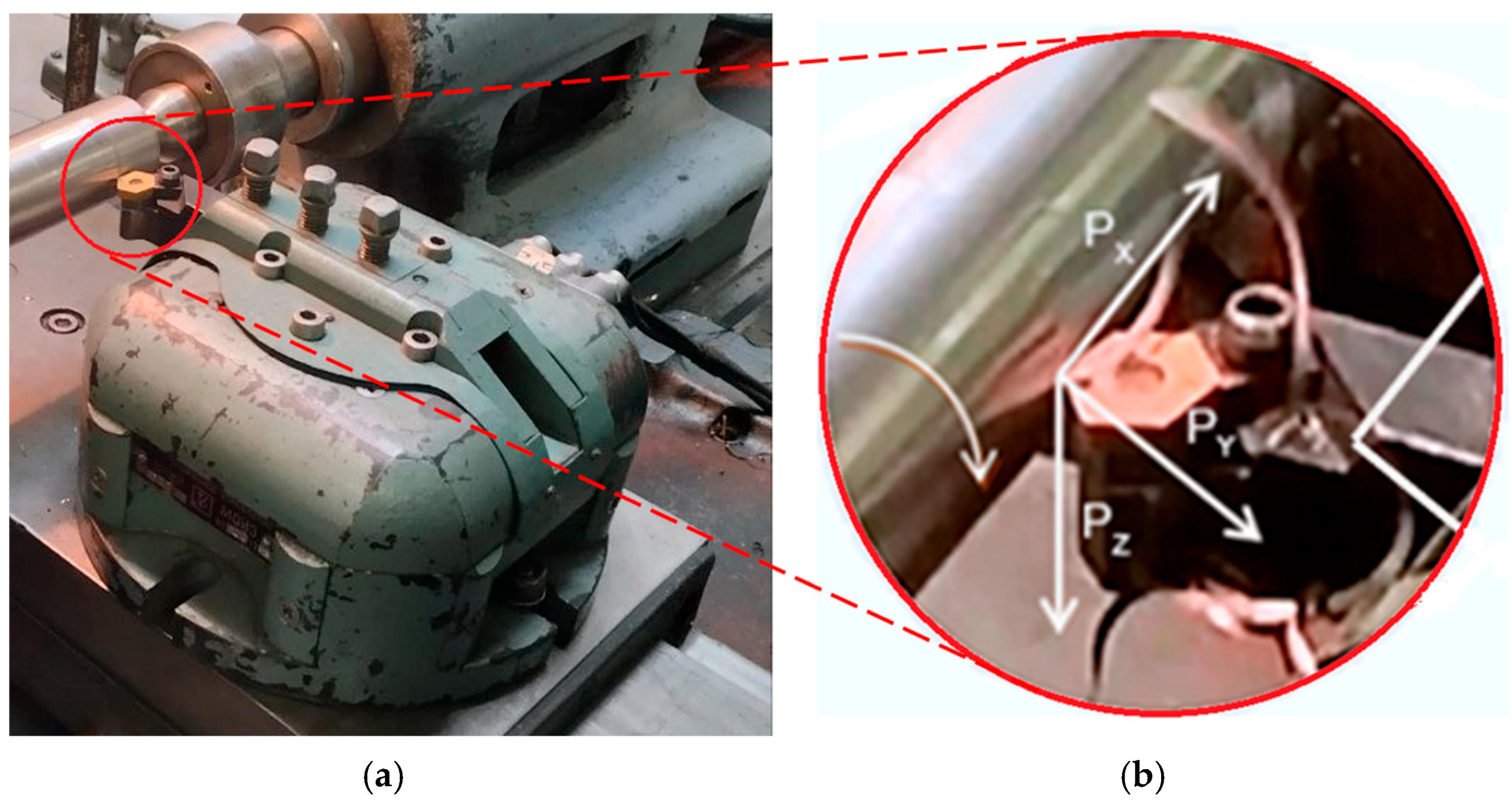
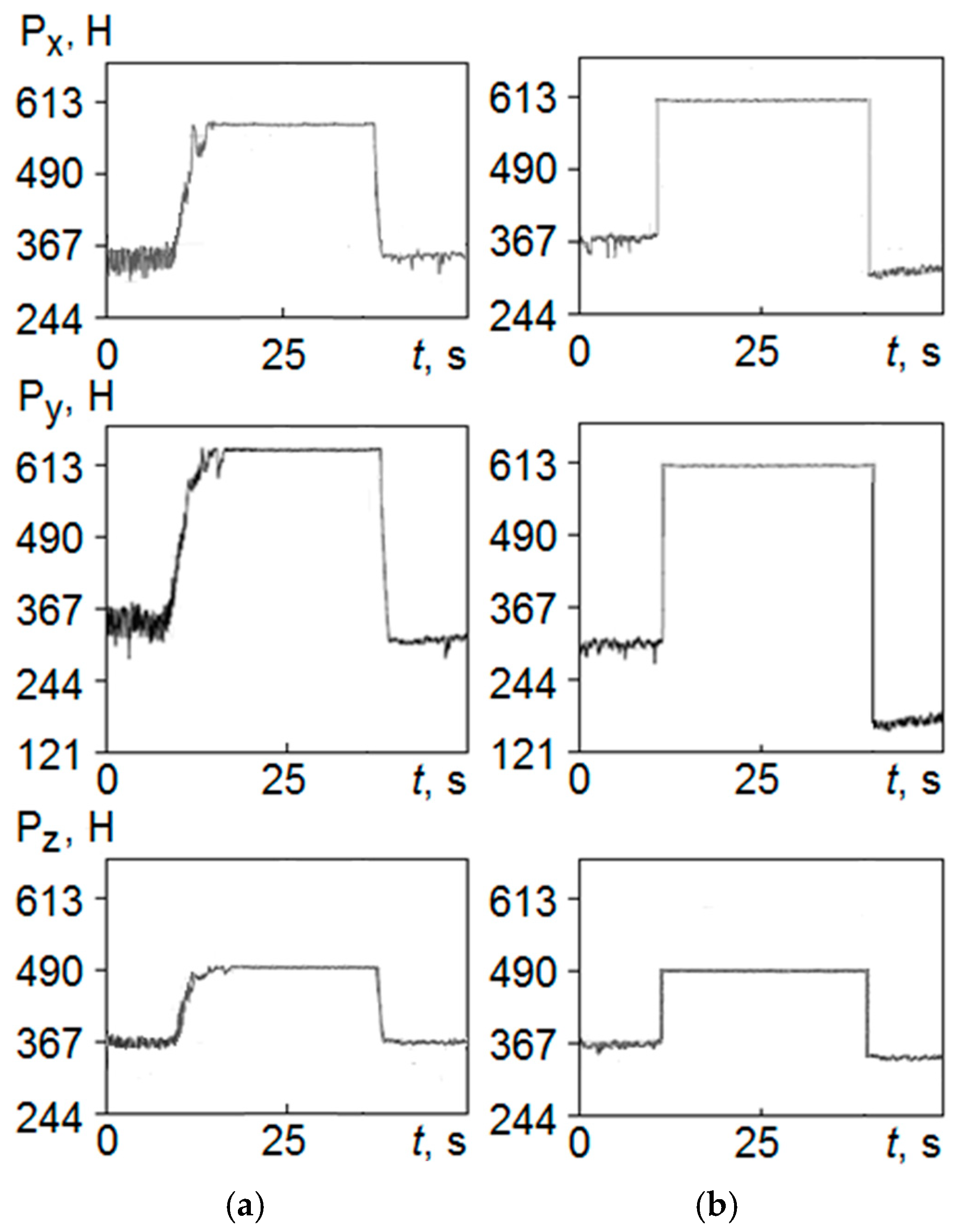
The cutting force components PX, PY, and PZ (Figure 9) measured by the UDM-600 dynamometer indicate that ductile copper can significantly affect the tribological properties of the composite coating [30] (Figure 8b), particularly by reducing the friction coefficient, which has a positive effect on the durability of carbide cutting tools with TiN-Cu coatings. This fact is confirmed by the fact that the measured cutting force components on uncoated plates are characterized by vibration (noise) [24] (Figure 9a); on the other hand, the time dependences of the cutting force components for coated plates are characterized by smoother indicators, indicating the absence of vibration (noise) (Figure 9b), although the force level is comparable to that of an uncoated plate, which can be indirectly explained by the effect of a decrease in the friction force on the durability of a cutting tool with a TiN-Cu coating. In addition to altering tribological properties, the addition of copper affects not only the coating structure but also significantly increases thermal conductivity [30], enhances heat dissipation from the contact zone between the tool’s cutting edge and the workpiece, and helps reduce temperature in the cutting zone.
Furthermore, Krysina O.V. [2] reported that TiN-Cu coatings containing approximately 12 at.% of Cu and exhibiting a microhardness of up to 45 GPa demonstrate a low coefficient of friction of 0.2, high adhesive strength to metal and hard alloy substrates exceeding 30 N, an increased degree of elastic recovery below 50%, high wear resistance under 2600 μm3/N·m, excellent thermal stability up to 1373 K, and enhanced oxidation resistance approaching 1073 K.
Figure 9.
Components of cutting forces PX, PY, and PZ: (a)—without coating; (b)—with TiN-Cu coating. Reprinted from [24] with permission from Advances in Applied Physics.
4. Discussion
Testing of TiN-Cu coatings demonstrated that, under actual operating conditions involving critical loads on hexagonal replaceable inserts of T15K6, the coatings did not fail, such as by chipping or delamination, within the contact area of the cutting instrument. This outcome clearly indicates the high adhesion quality of the TiN-Cu coating with respect to the T15K6 hard alloy, which was applied through hybrid plasma technology. Furthermore, the test results confirmed the wear resistance of TiN-Cu coatings. It was established that, under the specified application method of the TiN-Cu coating, the TiN composition containing 5.57 at. % of Cu extends the lifespan of T15K6 inserts by approximately 2.5 times compared with uncoated tools. Measurements of the cutting force components on TiN-Cu-coated inserts reveal no vibrations or noise during cutting, which can be indirectly attributed to the coating’s tribological properties. These properties contribute to increased tool longevity by reducing friction and enhancing heat dissipation at the contact zone between the tool’s cutting edge and the workpiece, thereby reducing temperature within the cutting zone.
An analysis of various studies showed similar findings: microhardness values at a copper concentration of approximately 2–7 at. % and a clear increase in wear resistance, along with a decrease in the friction coefficient. The microhardness values ranged from 30 GPa to 42 GPa, depending on the technological parameters of coating formation. The friction coefficient decreased by an average of three times, and wear resistance increased by an average of two times. This analysis revealed a very limited number of works that include tests under real operating conditions at critical loads. Wear resistance tests were mainly conducted using standardized tribological methods, primarily “ball-on-disk” (pin-on-disk or ball-on-disk method) [8,31]. The primary measured parameters are the dynamic friction coefficient and the geometric dimensions of the wear track (depth and width), which help estimate the volume of material lost and, consequently, the wear resistance. Some studies (e.g., Latushkina et al. [32]) also analyze the wear mechanism (plastic deformation versus fracture), and their results are confirmed in the current study, which used a different method specifically applicable to cutting tools to evaluate wear resistance.
5. Conclusions
A plasma–chemical reactor was designed that combines arc and magnetron discharge features. As a result, composite TiN-Cu coatings are produced through a combination of vacuum arc evaporation and planar magnetron operation. This streamlined technology enables effective modification of the structure and phase composition, thereby creating nanostructured, superhard, and ductile TiN-Cu coatings. Such coatings, about 6 μm thick, have been deposited onto replaceable hexagonal plates made from T15K6 hard alloy. The formation process involves titanium vapor reacting with atomic nitrogen in copper vapor, including nitrogen dissociation by plasma electrons, titanium vapor evaporation via a cathode spot, and copper vapor sputtering. The optimal synthesis parameters are an arc current of 90 A, magnetron current of 0.5 A, voltage of 400 V, gas pressure of 2.4 Pa, substrate temperature of 473 K, synthesis duration of around 15 min, substrate cleaning time of 10 min, and bias voltage of 160 V. XRD analysis shows no copper diffraction peaks in the composite layer, but X-ray spectral microanalysis indicates about 5.57 at. % copper throughout the coating. The microhardness ranges from 38 to 42 GPa.
The results obtained can be summarized in four points:
- A hybrid plasma–chemical reactor combining arc and magnetron discharges was developed to synthesize nanostructured TiN-Cu composite coatings on T15K6 hard-alloy inserts.
- Coatings about 6 μm thick with a uniform copper content of ~5.57 at.% were produced under optimized deposition conditions.
- X-ray diffraction revealed no separate copper phase, while microhardness reached 38–42 GPa.
- Wear tests under real cutting conditions demonstrated high adhesion, absence of chipping or delamination, and a significant improvement in tribological performance. As a result, the TiN-Cu coating increased the tool life of T15K6 inserts by approximately 2.5 times compared with uncoated tools, accompanied by reduced cutting forces and the absence of vibration due to decreased friction and enhanced heat dissipation in the cutting zone.
6. Patents
Patent No. 2649355 Russian Federation, IPC C23C 14/24 (14/06), B82B 3/00, B23B 27/14 Method for synthesizing TiN-Cu composite coatings and device for implementing it/A.P. Semenov, D.B.-D. Tsyrenov, I.A. Semenova: applicant and patent holder, Federal State Budgetary Scientific Institution, Institute of Physical Materials Science of the Siberian Branch of the Russian Academy of Sciences (RU)—No. 2017115297; declared 28 April 2017; published 2 April 2018, Bulletin No. 10. https://www1.fips.ru/registers-doc-view/fips_servlet?DB=RUPAT&DocNumber=2649355&TypeFile=html. (accessed on 30 January 2026)
The invention relates to a method and apparatus for synthesizing a superhard TiN-Cu composite coating and can be used to strengthen the working edges of cutting tools. The method involves synthesizing TiN using an arc-discharge current of 60–90 A in Cu vapor, dosed into the synthesis zone from the Cu vaporization zone, and sputtering Cu using a magnetron discharge at 0.6–1 A. The copper vapor is released through a slotted hole in the wall separating the Cu vaporization zone and the TiN synthesis zone. The apparatus comprises a vacuum arc evaporator, a planar magnetron, a vacuum chamber of the plasma–chemical reactor, a substrate holder, and a system for injecting the reaction gas (nitrogen). The plasma–chemical reactor chamber is divided by a diaphragm wall into two compartments: the TiN synthesis compartment and the Cu vaporization compartment. A slotted hole, coaxial with the magnetron’s axis of symmetry, is formed in the diaphragm wall. A planar magnetron and a vacuum-arc evaporator are installed: the former vertically, and the latter horizontally. The technical result is increased process efficiency, achieved by optimizing process parameters to synthesize a TiN-Cu composite coating with thermal stability, mechanical, tribological, and thermophysical properties and by controlling the formation of a nanostructured grain structure.
Author Contributions
Conceptualization, A.S. and D.T.; methodology, I.S. and N.U.; validation, I.S. and A.S.; investigation, D.T., I.S. and N.U.; resources, W.M. and U.M.; data curation, S.C.T. and G.E.T.; writing—original draft preparation, A.S.; writing—review and editing, S.C.T., G.E.T., W.M. and U.M.; supervision, A.S.; project administration, A.S.; funding acquisition, A.S. All authors have read and agreed to the published version of this manuscript.
Funding
This work was carried out with the financial support of the state assignment of the Ministry of Science and Higher Education of the Russian Federation, under scientific topic FWSF-2024-0010.
Data Availability Statement
The original contributions presented in this study are included in this article. Further inquiries can be directed to the corresponding authors.
Acknowledgments
This work was carried out using the equipment of the Science Center “Progress” of the East Siberia State University of Technology and Management, Ulan-Ude, Russia (ESSUTM).
Conflicts of Interest
Author Simon C. Tung was employed by Innovation Technology Consulting Inc. The remaining authors declare no conflicts of interest.
References
- Veprek, S.; Veprek-Heijman, M.G.J. Industrial applications of superhard nanocomposite coatings. Surf. Coat. Technol. 2008, 202, 5063–5073. [Google Scholar] [CrossRef] [Scilit]
- Krysina, O.V. Generation of Gas Metal Plasma in Low-Pressure Arc Discharges for Synthesis of Multicomponent Nanocrystalline Protective Coatings. Ph.D. Thesis, Siberian Branch of the Russian Academy of Sciences (SB RAS), Tomsk, Russia, 2016. (In Russian) [Google Scholar]
- Smyrnova, K.; Sahul, M.; Harssani, M.; Beresnev, V.; Truchlyy, M.; Caplovicc, L.; Caplovicova, M.; Kusy, M.; Kozak, A.; Flock, D.; et al. Composite materials with nanoscale multilayer architecture based on cathodic-arc evaporated WN/NbN coatings. ACS Omega 2024, 9, 17247–17265. [Google Scholar] [CrossRef] [Scilit]
- Bunshah, R.F.; Shabaik, A.H.; Nimmagadda, R.; Covy, J. Activated reactive evaporation for hard coatings. Thin Solid Film. 1977, 45, 453–462. [Google Scholar] [CrossRef] [Scilit]
- Vopat, T.; Sahul, M.; Haršáni, M.; Vortel, O.; Zlámal, T. The tool life and coating-substrate adhesion of AlCrSiN-coated carbide cutting tools prepared by LARC with respect to the edge preparation and surface finishing. Micromachines 2020, 11, 166. [Google Scholar] [CrossRef] [Scilit] [PubMed]
- Pogrebnjak, A.D.; Buranich, V.V.; Ivashchenko, V.I.; Baimoldanova, L.S.; Rokosz, K.; Raaen, S.; Zukowski, P.; Opielak, M.; Rakhadilov, B.K.; Beresnev, V.M.; et al. The effect of substrate treatment on the properties of TiAlSiYN/CrN nanocomposite coatings. Surf. Interfaces 2022, 30, 101902. [Google Scholar] [CrossRef] [Scilit]
- Bobzin, K. High-Performance coatings for cutting tools. CIRP J. Manuf. Sci. Technol. 2017, 18, 1−9. [Google Scholar] [CrossRef] [Scilit]
- Zhao, Y.; Zhao, S.; Ren, L.; Denisov, V.V.; Koval, N.N.; Yang, K.; Yu, B. Effect of Substrate Pulse Bias Voltage on the Microstructure and Mechanical and Wear-resistant Properties of TiN/Cu Nanocomposite Films. Rare Met. Mat. Eng. 2018, 47, 3284–3288. [Google Scholar] [CrossRef] [Scilit]
- Salek Rahimi, M.J.; Kianvash, A.; Memar, M.Y.; Rezvani, M. Characterization of Tin/Cu coating on a NiTi substrate using RF magnetron sputtering technique: Mechanical, structural, and biological characteristics of the coating. SSRN 2024. [Google Scholar] [CrossRef] [Scilit]
- Ivanov, Y.F.; Koval, N.N.; Krysina, O.V.; Baumbach, T.; Doyle, S.; Slobodsky, T.; Timchenko, N.A.; Galimov, R.M.; Shmakov, A.N. Superhard nanocrystalline Ti–Cu–N coatings deposited by vacuum arc evaporation of a sintered cathode. Surf. Coat. Technol. 2012, 207, 430–434. [Google Scholar] [CrossRef] [Scilit]
- He, J.L.; Setsuhara, Y.; Shimizu, I.; Miyake, S. Structure refinement and hardness enhancement of titanium nitride films by addition of copper. Surf. Coat. Technol. 2001, 137, 38–42. [Google Scholar] [CrossRef] [Scilit]
- Myung, H.S.; Lee, H.M.; Shaginyan, L.R.; Han, J.G. Microstructure and mechanical properties of Cu doped TiN superhard nanocomposite coatings. Surf. Coat. Technol. 2003, 163–164, 591–596. [Google Scholar] [CrossRef] [Scilit]
- Semenov, A.P.; Tsyrenov, D.B.-D.; Semenova, I.A. Method of Synthesis of TiN-Cu Composite Coatings and Device for Its Implementation. Patent for Invention RU2649355C1, 2 April 2018. [Google Scholar]
- Semenov, A.P.; Tsyryonov, D.B.-D.; Ulakhanov, N.S.; Semenova, I.A. Synthesis of TiN coatings in Cu vapor on T15K6 alloy using the hybrid plasma technology. Appl. Phys. 2025, 2, 97–102. Available online: https://applphys.orion-ir.ru/appl-25/25-2/PF-25-2-097_RU.pdf (accessed on 30 January 2026).
- Semenov, A.P.; Tsyrenov, D.B.-D.; Semenova, I.A. An apparatus for vacuum deposition of composite TiN−Cu coatings. Instrum. Exp. Tech. 2017, 60, 892–895. [Google Scholar] [CrossRef] [Scilit]
- Tsyrenov, D.; Semenov, A.; Smirnyagina, N. Modernization features of a vacuum installation based on low-pressure arc discharge for composite TiN-Cu layers formation. Acta Polytech. 2015, 55, 136–139. [Google Scholar] [CrossRef] [Scilit]
- GOST 19068-80; Indexable Carbide Throw-away Square Cutting Inserts with Hole Dimensions. Standards Publishing House: Moscow, Russia, 1980.
- GOST 9450-76; Measurements of Microhardness by Diamond Indenter Static Indentation Method. Standards Publishing House: Moscow, Russia, 1976.
- Manual for Universal UDM Dynamometer of VNII Design; VNII Publ.: Moscow, Russia, 1983; Available online: https://search.rsl.ru/ru/record/01009406722 (accessed on 30 January 2026).
- GOST 19047-80; Indexable Carbide Throw-away Triangular Cutting Inserts with Hole Dimensions. Standards Publishing House: Moscow, Russia, 1980.
- Belyanin, A.F.; Pashchenko, P.V.; Semenov, A.P. RF magnetron sputtering apparatus for growing thin films. Instrum. Exp. Tech. 1991, 3, 220–222. [Google Scholar]
- Veprek, S.; Reiprich, S. A concept for the design of novel superhard coatings. Thin Solid Film. 1995, 268, 64–71. [Google Scholar] [CrossRef] [Scilit]
- Musil, J.; Vlcek, J. Magnetron sputtering of alloy and alloy-based films. Thin Solid Film. 1999, 343–344, 47–50. [Google Scholar] [CrossRef] [Scilit]
- Semenov, A.P.; Tsyryonov, D.B.-D.; Ulakhanov, N.S.; Semenova, I.A. Deposition of superhard TiN-Cu coatings on T15K6 alloy in a vacuum plasma-chemical reactor. Adv. Appl. Phys. 2025, 13, 314–322. Available online: https://advance.orion-ir.ru/UPF-25/4/UPF-13-4-314_RU.pdf (accessed on 30 January 2026).
- Myung, H.S.; Han, J.G.; Boo, J.H. A study on the synthesis and formation behavior of nanostructured TiN films by copper doping. Surf. Coat. Technol. 2004, 177–178, 404–408. [Google Scholar] [CrossRef] [Scilit]
- Eremenko, V.N.; Buyanov, Y.I.; Prima, S.B. Phase diagram of the system titanium–copper. Powder Metall. Met. Ceram. 1966, 5, 494–502. [Google Scholar] [CrossRef] [Scilit]
- Dobromyslov, A.V.; Kazantseva, N.V. Phase transformations in titanium–copper system alloys. Fiz. Met. Metalloved. 2000, 89, 47–53. English translation in Phys. Met. Metallogr. 2000, 89, 460–466. (In Russian) [Google Scholar]
- Kelkar, G.P.; Carim, A.H. Synthesis, properties, and ternary phase stability of M6X compounds in the Ti-Cu-O system. J. Am. Ceram. Soc. 1993, 76, 1815–1820. [Google Scholar] [CrossRef] [Scilit]
- Shuliak, Y.I.; Vasilev, V.G. A Modernized UDM-600 Dynamometer-Based Setup for the Cutting Force Measurement. Mach. Plants: Des. Exploit. 2016, 16, 1–12. [Google Scholar] [CrossRef] [Scilit]
- Blinkov, I.V.; Volkhonsky, A.O.; Laptev, A.I.; Sviridova, T.A.; Tabachkova, N.Y.; Belov, D.S.; Yershova, A.V. Ceramic-metallic (TiN-Cu) nanostructural ion-plasma vacuum-arc coatings of cutting carbide tools. Powder Metall. Funct. Coat. 2013, 2, 54–59. [Google Scholar] [CrossRef] [Scilit]
- Wang, H.; Shu, X.; Guo, M.; Huang, D.; Li, Z.; Li, X.; Tang, B. Structural, tribological and antibacterial activities of Ti–Cu–N hard coatings prepared by plasma surface alloying technique. Surf. Coat. Technol. 2013, 235, 235–240. [Google Scholar] [CrossRef] [Scilit]
- Latushkina, S.D.; Ramanau, I.M.; Zhizhchenko, A.G.; Pasylkina, O.I.; Kamarouskaya, V.M.; Piskunova, O.Y. Formation of wear-resistant TiN/Cu nanoscale coatings. Trenie Iznos 2016, 37, 36–41. English translation in J. Frict. Wear 2016, 37, 33–37. (In Russian) [Google Scholar]
Disclaimer/Publisher’s Note: The statements, opinions and data contained in all publications are solely those of the individual author(s) and contributor(s) and not of MDPI and/or the editor(s). MDPI and/or the editor(s) disclaim responsibility for any injury to people or property resulting from any ideas, methods, instructions or products referred to in the content. |
© 2026 by the authors. Licensee MDPI, Basel, Switzerland. This article is an open access article distributed under the terms and conditions of the Creative Commons Attribution (CC BY) license.