


Abstract
The results of experimental tests of six various water-lubricated bearings are described. Tests were performed under conditions typical for marine stern tube bearings. The acquired low-friction coefficient values indicated that the bearings operated in the fluid friction regime over a wide range of sliding speeds and loads. Due to elastic deformations of the flexible non-metal bushings, it was not possible to measure the lubricant film thickness to confirm this phenomenon. Studying measured hydrodynamic pressure distribution profiles, and thanks to lifting force calculation, it was proven that hydrodynamic phenomena occur between strongly deformed, rough surfaces lubricated by a low-viscosity fluid.
1. Introduction
The history of marine propeller shaft bearings is as old as the history of mechanical ship propulsion. In the middle of the 19th century, propeller propulsion began to replace paddle propulsion, and with increases in the sizes of ships, the diameters of the shafts increased simultaneously. Over time, greater and greater demands were placed on the drive systems in terms of their durability and reliability. The revolutionary, 200 m long iron ship Great Eastern, launched in 1864, featured screw propulsion, paddle wheels and sails; however, after its first voyage across the Atlantic, a propeller shaft bearing failed. A decision was made to replace the water-lubricated bearing with its white metal bushing with a wooden bushing. This is probably the first example of the failure of a ship’s propeller shaft bearing described in the literature, and also the first report on the use of lignum vitae wood as a bearing bush [1].
The rapid development of hydropower at the beginning of the 20th century led to a search for a safe solution for the bearings of water turbines [2]. The significant achievements in engineering in the 20th century meant that design solutions were improved and new materials were used, such as rubber bushings, which were patented in 1924 [1]. The development of seals enabled the use of oil as a lubricant in ship propeller bearings and water turbine bearings. In the period following the 1950s, the development of specialized polymers allowed for the manufacturing of plain bearing shells from various polymers. Although lignum vitae wood has not been forgotten, trade in this material is not easy due to environmental protection regulations, for example, CITES (Convention on International Trade in Endangered Species of Wild Fauna and Flora 1973). Any trade involving endangered species generally requires a CITES export permit or re-export certificate to be granted by the exporting country before the transaction occurs. Currently, limiting emissions and reducing pollution from transport have become primary concerns in many countries, and an important goal is to introduce safe, reliable, zero-emission unmanned ships into operation. Experiments on alternative [3,4,5] and hybrid drives are currently being conducted by many researchers around the world [6,7,8,9].
Water-lubricated bearings are considered an environmentally friendly solution. After 150 years of experience, engineers are also able to design reliable bearings with high durability, and there are numerous examples of applications in which the durability of such bearings exceeds 30 years [10]. However, there are also cases of frequent failure or rapid, unexpected wear, especially when the lubricant is water contaminated with solid particles [11,12], meaning that sealed, oil-lubricated bearings are still popular. Unfortunately, permanent leaks, partly caused by failures of the bearings or seals, result in serious environmental contamination. It has been estimated that up to 28.6 million liters of oil are released annually into marine waters from stern tubes [13]. When regulation limiting oil leaks was introduced in 2013 [14], more complex, environmentally safer seals and environmentally friendly oils called EALs (environmentally adaptable lubricants) began to be used [15], although it seems that the popularity of water-lubricated bearings has not increased. Experts estimate that between 5% and 6% of the 100,000 to 120,000 ships operating around the world use water-lubricated stern tube bearings [16].
Despite this, a revolution is imminent, as new environmental protection acts aimed at the elimination of PFAS (per- and polyfluoroalkyl substances) [17,18] from a variety of products are to be introduced in the near future. As a result, a ban may be introduced on many widely used materials, including those commonly used for the production of plain bearing shells, such as PTFE. Better knowledge about the influence of microplastics also plays a significant role [19]. Hence, there are now unique conditions favoring the reintroduction of old, proven materials of natural origin, such as wooden bearings grown on ecological plantations. However, the gradual decrease in the application of wood resulted not only from limited resources of the raw material, scant availability, and high price, but also from its disadvantages. For example, it has a rather complex structure, with uneven swelling resulting from the natural anisotropic structure over time, which causes changes in the bush geometry that are difficult to predict, and which affects the generation of the fluid film in the bearing.
The research presented here aimed to examine five different bearing materials accepted for marine applications. One of them, known for centuries, is still in focus, and its popularity has recently grown: lignum vitae bearings made according to industrial standards under relevant operating conditions, using extensive instrumentation. Lignum vitae belongs to the family Zygophyllaceae and the genus Guaiacum. The only other tree genera in this family are Polrlieria and Bulnesia. In the genus Guaiacum, there are five different species, of which only two, Guaiacum officinale and Guaiacum sanctum, have an important role in engineering [20] as construction materials with special properties, such as outstanding friction and wear characteristics. Due to environmental and economic limitations, some alternatives are being offered on the market that use natural wood species saturated with resins. Wood species reported in the literature include hard wax-impregnated rock maple (Acer saccharum), basswood (Tilia americana), and muninga (Pterocarpus angolensis). Beech wood (Fagus sylvatica) has also been reported as being used in the form of pressed blocks impregnated with synthetic resins [21].
Testing of full bearings with considerable diameter is rather rarely reported in the literature, although smaller, specimen-scale research studies have been performed. For example, in [22], the influence of the orientation of fibers on the wear rate and mechanism was tested in dry and water lubrication, using scratch tests and ball-on-flat specimens. In a specimen-scale experiment, lignum vitae specimens were tested with special treatments including lignin removal and infusion of polydimethylsiloxane (PDMS) in a vacuum, which had a beneficial effect on the wear rate and friction coefficient (COF) in dry friction conditions [23]. Another approach was presented by Wu et al. [24], who tested thermoplastic polyurethane modified with lignum vitae chips and found improved friction and wear properties under water lubrication conditions, due to their increased hardness and improved hydrophilicity, which enhanced the effective formation of water films. Some examples of research into environmentally friendly material solutions for marine applications, such as specimen-scale testing of lignum vitae wood-based composites, are presented in [25,26,27].
Polymer-based composites were also tested with the addition of small proportions of lignum vitae to improve self-lubricating conditions at high loads and low speeds, at the specimen scale, by Guo et al. [26]. Water-lubricated bearings have attracted attention from researchers given their expected lower friction losses [27]. As mentioned above, although there are numerous examples in which polymer-based and water-lubricated bearings have operated with adequate durability, there are also examples (e.g., in hydropower) when the conversion was not as successful as expected, and the reintroduction of lignum vitae bearings has provided a remedy.
In addition to the potential benefits of lignum vitae and the imminent introduction of strict regulations, which may remove many widely used materials from the market, there are many industrial applications for lignum vitae [21]; however, although there have been numerous small-scale research studies, there has been virtually no component-scale research in which systematic tests of lignum vitae bearings under realistic operational conditions have been presented.
It is also worth noting that in some research centers, some very ambitious projects connected with stern tube bearings are being conducted. Researchers have addressed problems with dynamic loading as a result of slumming [28,29,30,31], partial propeller immersion [32], and the impact of waves [33], and novel numerical models have been proposed [34,35,36].
2. Methods
For safety reasons, all of the components of a ship need to be accepted by a classification society, meaning that some specific requirements must be met. Water-lubricated stern tube bearings with non-metallic bearing bushes also need to be accepted. In the relevant regulations, it is possible to find some important data, such as the length-to-diameter ratio for a bearing bush, working clearance, or recommended geometry, for example. Not every bearing bush material is accepted for marine applications; in addition, the certification process is expensive, and some companies are not interested. However, if companies want to be competitive in the market, some tribology tests (friction and wear) are necessary. There is no global standard for such tests.
Relatively low bearing-specific loads, usually below 0.6 MPa, combined with quite high sliding speeds, are good conditions for full film lubrication, with the benefits of low friction losses and high durability resulting from the lack of contact between rubbing elements. In practice, however, it turns out that excessive bearing clearance, incorrect geometry or significant shaft misalignment during operation can result in decreased durability. During many years of research, a method for measuring the thickness of the lubricant film was developed [37], but it is not feasible once the bush deformations are significant. Such a situation often occurs in the case of water-lubricated bearings with non-metallic bushes. The search for an appropriate method for assessing hydrodynamic load capacity [38] led to the studies on the measured pressure distribution in the lubrication gap. The measurements carried out using a rotating sensor placed in the shaft proved to be of little use due to the dynamics of the entire process. Installing the sensors in the bush proved to be a better choice. It was possible to record pressure fluctuations, which are usually small for stable operating conditions.
Testing of ship stern tube bearings is not an easy task for many reasons, one of the most important being the fact that marine bearings are large, with shaft diameters reaching 1000 mm, meaning that real-scale testing is almost impossible. Other factors, such as cooling conditions, shaft alignment, or specific loading by a rotating propeller, make cases of this type hard to test in the laboratory, and for this reason, custom-designed and built test rigs at different research laboratories have designs that are different from a typical stern tube configuration. One of the custom designed and built test rigs at the Tribology Laboratory of Gdansk University of Technology was used in this study for the testing of wooden bearing bushes. The methodology was applied in tests carried out for leading classification societies and some of the global bearings suppliers. One of the advantages of this system is that bearings with a diameter of 100 mm can be tested, representing a practical compromise between testing costs and size, as this is a realistic size for bearings used on small vessels such as fishing vessels.
2.1. Bearing Bushes
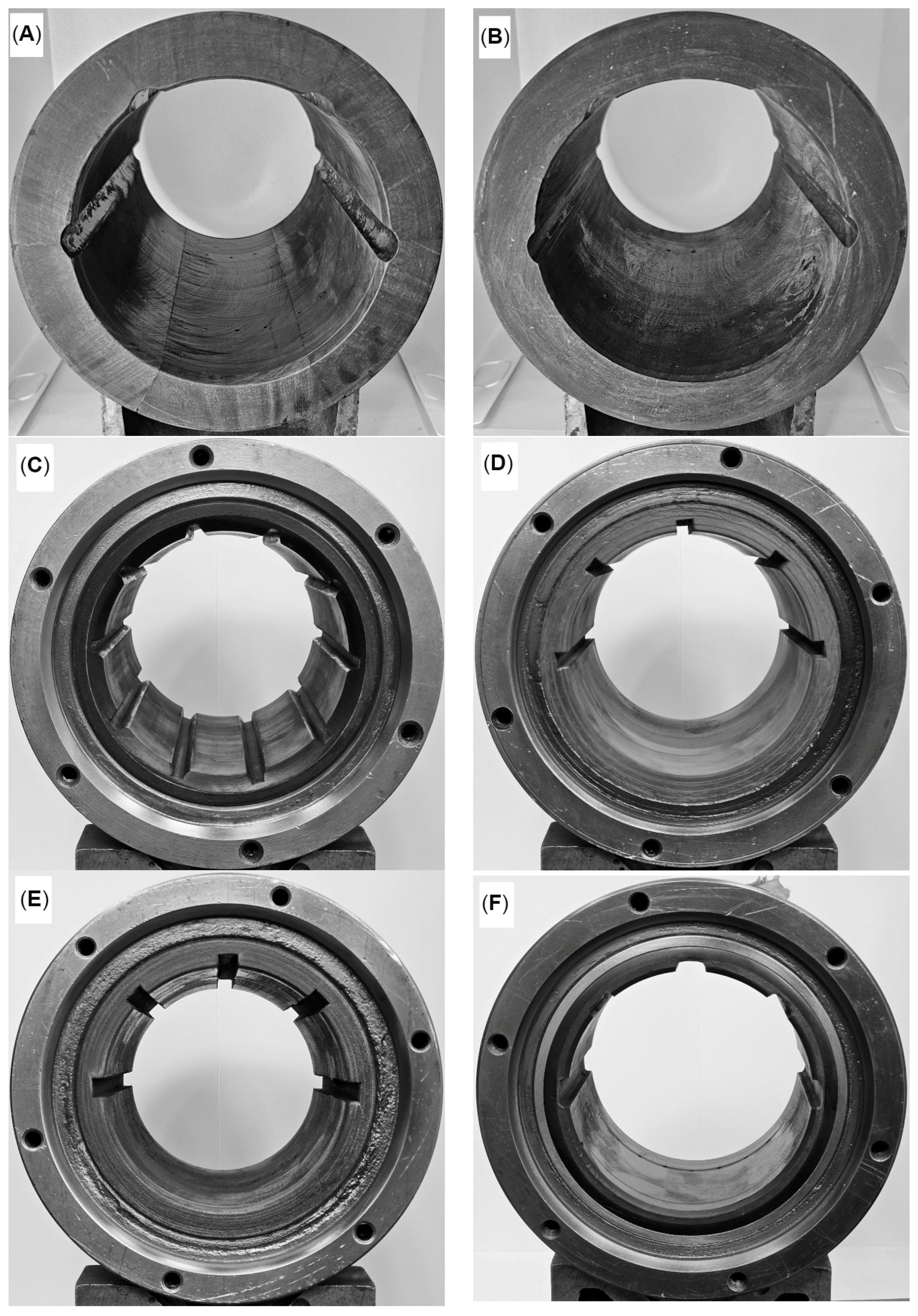
Six bearing bushes were tested (Figure 1, Table 1) under conditions relevant to marine stern tube bearings (Table 2). The first one (Figure 1A) was made of six pieces, with the transversal grain location with respect to the sliding direction. This kind of bearing bush assembly helps in achieving higher durability under operational conditions. The second type (Figure 1B) was a “one-piece” bush. The lubrication groves were located only on both sides of the bush to provide good cooling conditions as a result of lubricant flow. The lower, loaded part was smooth, and after running-in, the surface roughness was significantly improved.
Figure 1.
The tested bearing bushes: (A) wooden—lignum vitae, a six-piece glued bearing bush with transversal wood grains location; (B) wooden—lignum vitae, a one-piece bearing; (C) NBR bearing, (D) polymer bearing, (E) composite bearing, (F) 3-layer bearing.
Table 1.
Tested bearings list with material properties data.
NBR (nitrile butadiene rubber) is one of the most common materials used for over a hundred years for the bushes of water-lubricated propeller shaft bearings (Figure 1C). This material has several advantages, such as ease of production, global availability, and low prices. Due to its flexibility, it dampens the vibrations of the ship’s propeller shaft well. It is commonly used in open lubrication systems when the filtered seawater is used as a lubricant. Studies have also proven that it operates well in cases when the lubricant is contaminated with solid particles of mineral origin—this is typical for some water bodies, e. g., shallow waters and river estuaries. This is because the contamination is not crushed by the rubbing friction pair, and the particles migrate between the shaft and the bush and are washed out by the water [12]. The effect of such migration of particles pressed against the shaft by the rubber bush is the gradual destruction of the shaft surface. Therefore, the shaft is usually subjected to expensive regeneration during inspections and repairs every ten years. The second significant disadvantage of this material is the high coefficient of static friction.
The fourth material selected for comparison was a popular resilient polymer (Figure 1D). This is a plastic with a low melting point, which may be important in emergencies. This is a popular solution supplied to the market by several manufacturers who have obtained certification for their products. There are known cases of successful applications when the bearing operated for thirty years with a gradually, predictably progressing wear process. The fifth material in the comparison is a fabric-reinforced composite (Figure 1E). This is a popular type of material in shipbuilding. The reinforcement ensures high shape stability, as a result of water absorption and, as a result, temperature increase. The limitation results from higher stiffness than other materials, which is often important when the shaft is misaligned with respect to the bush. The sixth material—a three-layer composite (Figure 1E) with a sliding surface made of PTFE—has several significant advantages. It has good vibration damping, a low coefficient of static and moving friction at low and very low sliding speeds, and works well in conditions when the lubricant is contaminated. Importantly, all tested bearings were made by certified suppliers in accordance with their recommendations regarding bearing clearance, surface roughness, and arrangement of lubrication grooves.
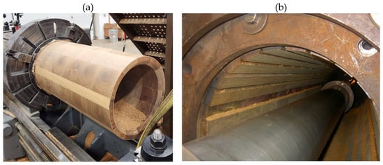
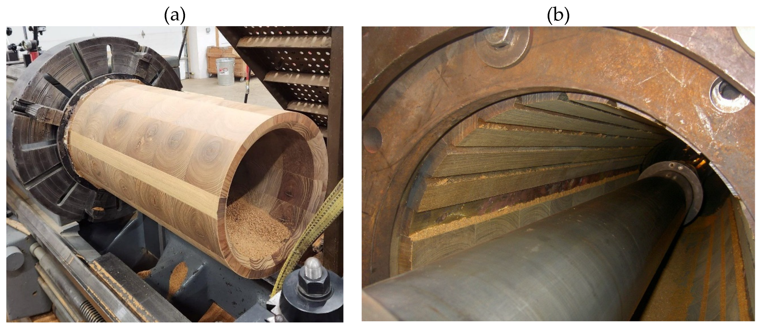
All bearings were machined before installation in the steel housing. This method has some advantages and disadvantages. The manufacturing process was conducted by a specialist in a professional workshop (Figure 2a), although in this case, the bearing has to be press-fitted into a precisely prepared housing, and any imperfection in the housing is likely to be transferred to the bush sliding surface [37]. The new generation of machining tools can help to achieve a high quality for the sliding surface when the final process is conducted after installation of the wooden bush in the steel housing (Figure 2b).
Figure 2.
Manufacturing a wooden bearing bush: (a) a bush ready for installation during final turning; (b) machining of the bush after installation in the stern tube (authors’ archive).
The especially sensitive, wooden bearing bushes were delivered in special packaging that was filled with water, so that they would not be damaged or dry out during transport.
2.2. Operational Conditions
Operational conditions were similar to those present in marine stern tube bearings (Table 2).
Table 2.
Test rig details and operational conditions.
2.3. The Test Rig
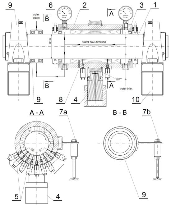
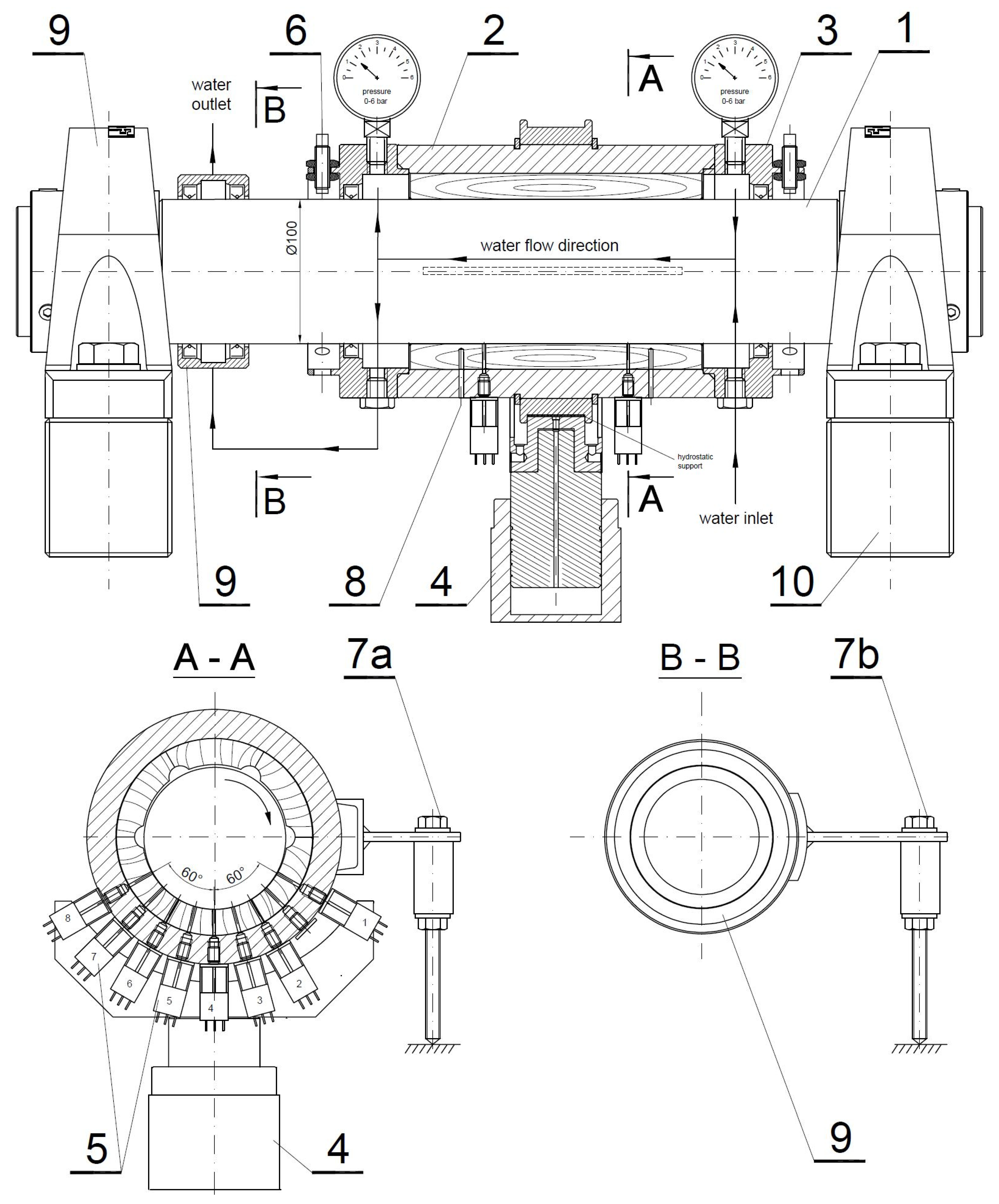
The test stand was specially designed and built for testing the sliding bearings of marine drive shafts (Figure 3). The tested plain bearing assembly (2) was installed on the main shaft with a diameter of 100 mm, supported on two ball bearings in self-aligning housings. The test rig was powered by an electric motor with a reduction gear controlled by an AC controller.
Figure 3.
Cross-section of the test rig: (1) main shaft; (2) steel housing with lignum vitae bearing bush; (3) covers with seals; (4) load cell; (5) pressure sensors; (6) proximity sensors; (7a) friction force sensor—for bearing unit; (7b) friction force sensor—for seals module; (8) holes for thermocouple installation; (9) sealing module; (10) ball bearing supports. A-A cross section with the arrangement of the pressure measurements, B-B cross-section through the arm to measure seal section friction.
The bearing shell under test was Installed in a rigid steel housing. To enable water to be pumped through it, covers with seals (3) were installed on both sides of the bearing. The load was exerted by a hydraulic cylinder via a hydrostatic bearing, to which high-viscosity oil was pumped from an independent unit. Using this method of applying a load, it was possible to precisely measure the friction torque (at force sensor 7a) generated by the bearing assembly (2). To increase the precision of the measurement and to take into account the friction torque of the sealing rings on the shaft of the bearing assembly, an additional module was installed on the shaft in order to measure the friction torque of the seals only (9). Finally, after subtracting the value of the friction force of the seals (7b) from the bearing assembly (7a) it was possible to calculate the value of the COF.
During the tests, we also measured the hydrodynamic pressure distribution in the lubricant film (5), the trajectory of the shaft axis (using non-contact displacement sensors) (6), and the temperature of the lubricant at the inlet and outlet.
An important role is played by the distance sensors (6), mounted in pairs on both sides of the tested bush (L—left, R—right). Thanks to them, it is possible to record the position of the shaft during the bearing operation, i.e., the so-called orbit.
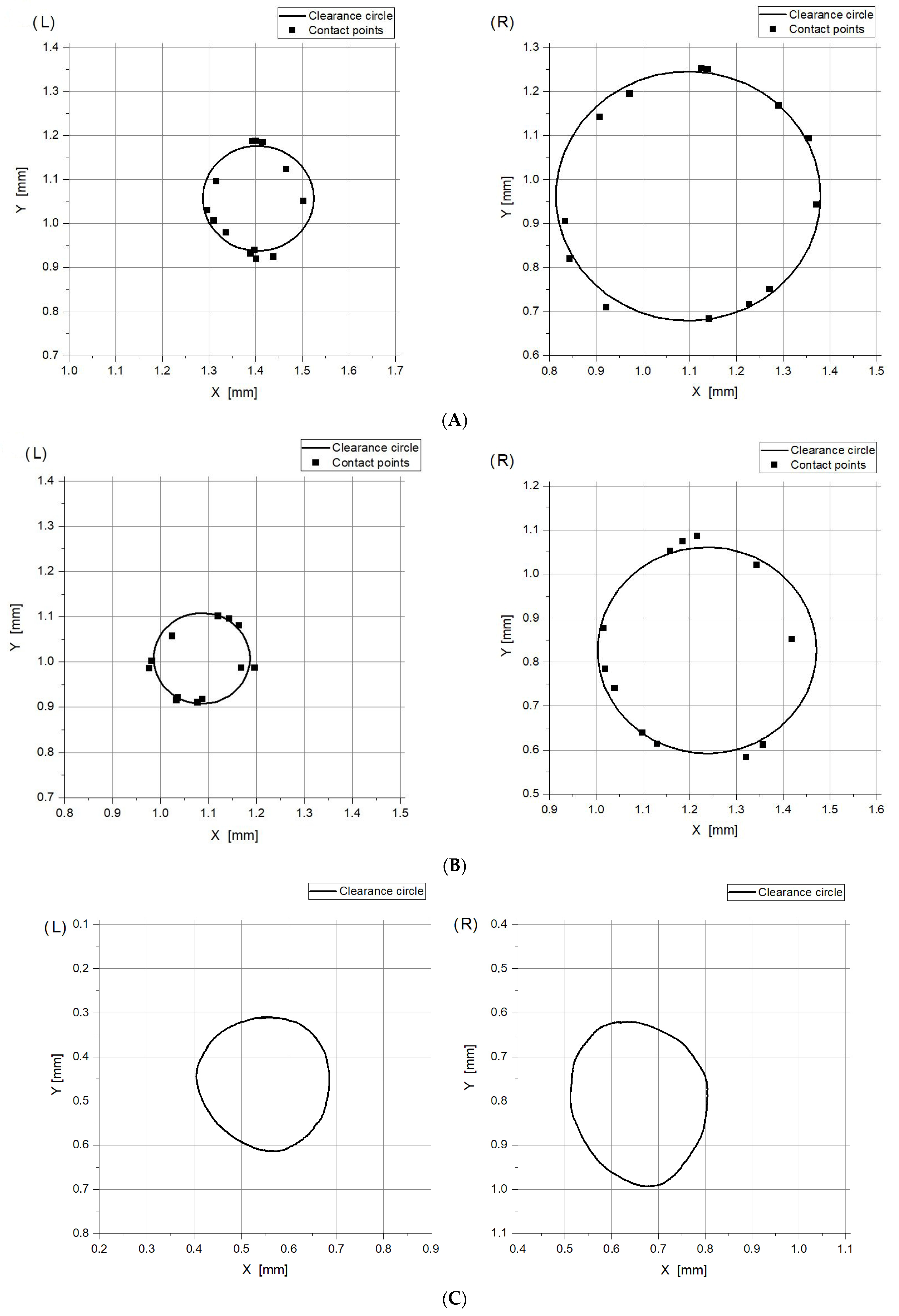
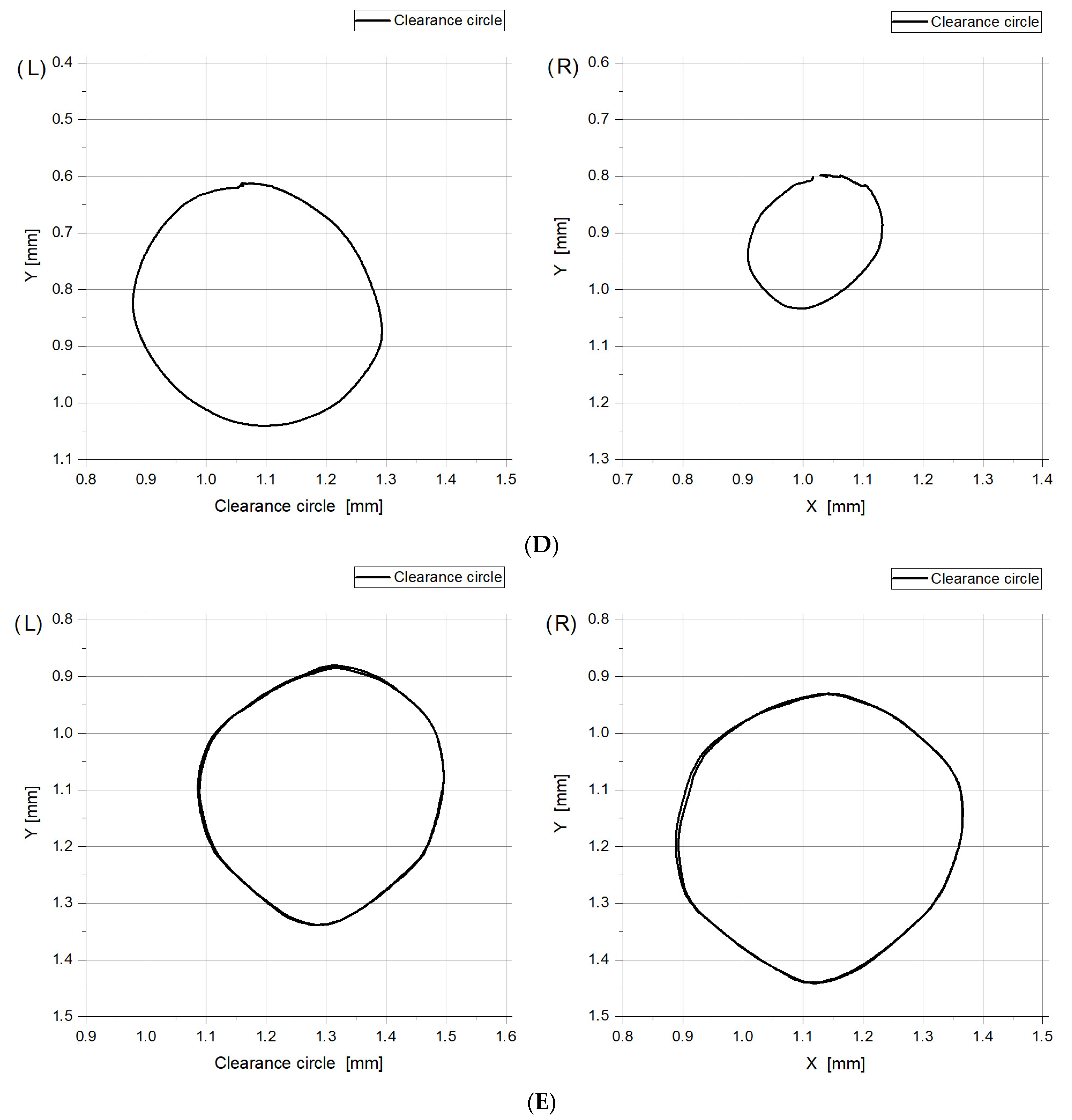
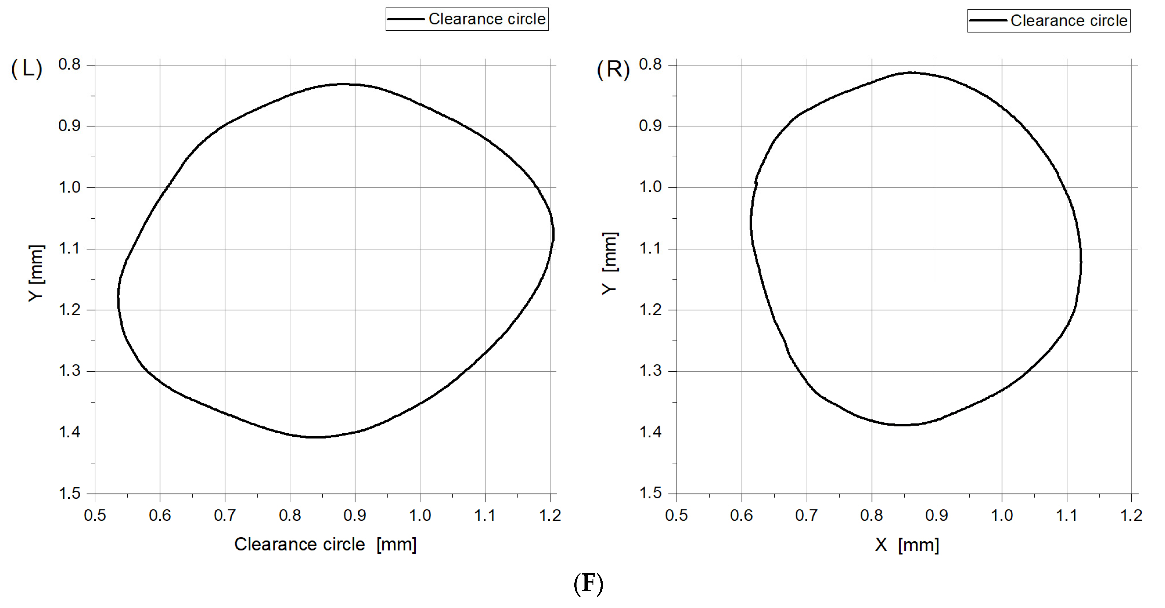
The design of the stand allows for recording the clearance circle, in the case when the bush is perfectly cylindrical. Since the bush is normally not perfect in shape, due to deformations, swelling, and, over time, also wear, the bush cylindricity error can be assessed (Figure 4). The measurement can be carried out in two ways. The contact points can be recorded, and the ideal clearance circle can be drawn on their basis (Figure 4A,B). The trajectory of the shaft and bush contact can also be recorded (Figure 4C–F). The first method allows for calculating the thickness of the lubricant film, and the second one exposes the circularity errors of the tested bushes.
After assembly, the tested bearings were subjected to a running-in process, gradually increasing the load with initially high and then gradually lower rotational speeds. The running-in process was carried out over several hours, after which the movement resistance diagrams reached a typical shape for a water-lubricated bearing, where hydrodynamic phenomena occur despite the low viscosity of the lubricant film [38,39].
The conducted tests allowed:
- Comparison of the results of resistance to motion based on the calculated values of the friction coefficient;
- Comparison of the bearing clearance and the degree of bush deformation resulting from machining, mounting in the sleeve (pressure or shrinkage), and water absorption (Figure 4);
- Measuring the trajectory of the shaft axis during the test, but due to the elastic deformation of the bush, it was not possible to determine the thickness of the lubrication film (Figure 5);
- Distribution of hydrodynamic pressure in the lubrication gap, which allows for the identification of the hydrodynamic lifting force.
3. Results and Discussion
The tests were carried out in two stages, which involved mounting the bearings and running-in and conducting measurements a few times to ensure that the measurement results were reliable. In the authors’ opinion, the results of the measurements of the shaft axis trajectories and their locations in relation to the experimentally recorded contact points between the shaft and the bearing are the most important (Figure 4). For bearings with metal sleeves, when precise machining is possible, the experimentally determined contact points practically coincide with a circle determined using the least squares method; however, for bearings with non-metallic bushings, larger inaccuracies can usually be expected, primarily due to cylindricity errors [40,41,42]. The results obtained here and the cylindricity error for the tested bushes were not surprising (Table 1, Figure 4), as there was a much larger clearance at the inlet side (right-hand side of Figure 4) than at the outlet side.
In the figures below (Figure 4A,B) it is possible to observe twelve contact points acquired experimentally and the clearance circle calculated based on the least squares method. Alternatively, the results of the measured clearance circles when the shaft is rolled around the circumference of the bush are shown below (Figure 4C–F). It is not possible to calculate the thickness of the lubricant film, but the shape errors are clearly visible. Such a measurement is very accurate—this can be seen in the graph Figure 4E, when the entire measurement cycle was performed twice, and the clearance circles practically overlap.
Figure 4.
(A). Experimentally measured contact points between the shaft and bush, and circles of clearance; natural wood—lignum vitae bearing A (L—left side and R—right side of the tested bearing). (B). Experimentally measured contact points between the shaft and bush, and circles of clearance; natural wood—lignum vitae, one-piece bearing B (L—left side and R—right side of the tested bearing). (C). Experimentally measured contact points between the shaft and bush, and circles of clearance; nitrile rubber (NBR) bearing C (L—left side and R—right side of the tested bearing). (D). Experimentally measured contact points between the shaft and bush, and circles of clearance; elastomer bearing D (L—left side and R—right side of the tested bearing). (E). Experimentally measured contact points between the shaft and bush, and circles of clearance; composite with fibers bearing E (L—left side and R—right side of the tested bearing). (F). Experimentally measured contact points between the shaft and bush, and circles of clearance; 3-layer bearing F (L—left side and R—right side of the tested bearing).
The errors involved in determining the contact circle and the flexibility of the bushing material make it very difficult to estimate the thickness of the lubricant film. Such a case occurred for all tested bearings. There is no doubt that the shape errors associated with the bush meant that in the bearings tested here, there were unfavorable conditions for the formation of thick lubricant films of high load-carrying capacity (Figure 5 and Figure 6). However, the small sizes of the orbits and their repeatability are noteworthy, as each graph shows the results for three consecutive revolutions of the shaft. Quite unexpectedly, one can observe that with the increase of speed the orbits become smaller, as if the shaft was stabilized in a better way in the bearing. Most probably it is due to the fact that at higher speeds the load is carried entirely by the water film and no occasional bush/shaft contacts occur, which is more probable at lower speeds. These occasional contacts cause larger amplitude observed in the graphs. The reason why this behavior seems strange may also be caused by a specific configuration of the test stand. The shaft is located in two roller element bearings and does not have any freedom to oscillate (with respect to non-moving coordinate system). What can be observed in the graphs are in fact oscillations of the housing with respect to the shaft. The housing oscillates between the water film of the tested bearing and the hydrostatic oil film of the cylindrical hydrostatic support, which keeps the housing in place, while providing freedom to rotate (so that the torque can be precisely measured). In terms of dynamics, the situation is quite complex as both the films have different stiffnesses and dampings, and the wooden bush also deforms. We do not discuss the rotodynamic problems, as the orbits are not of the same origin as in an usual configuration, and, what is even more important, the shaft stability will not be a problem in real ship propulsion systems because there the large load of the shaft weight and a heavy propeller will cause the fluid film bearing (especially of the water-lubricated one) to operate with very thin films at large eccentricity values and no danger of instability.
Figure 5.
Shaft axis trajectories and clearance circles for bearing A, specific pressure 0.3 MPa: (a) left side of the bearing; (b) right side of the bearing; (c) magnified view of the trajectories, left side; (d) magnified view of trajectories, right side.
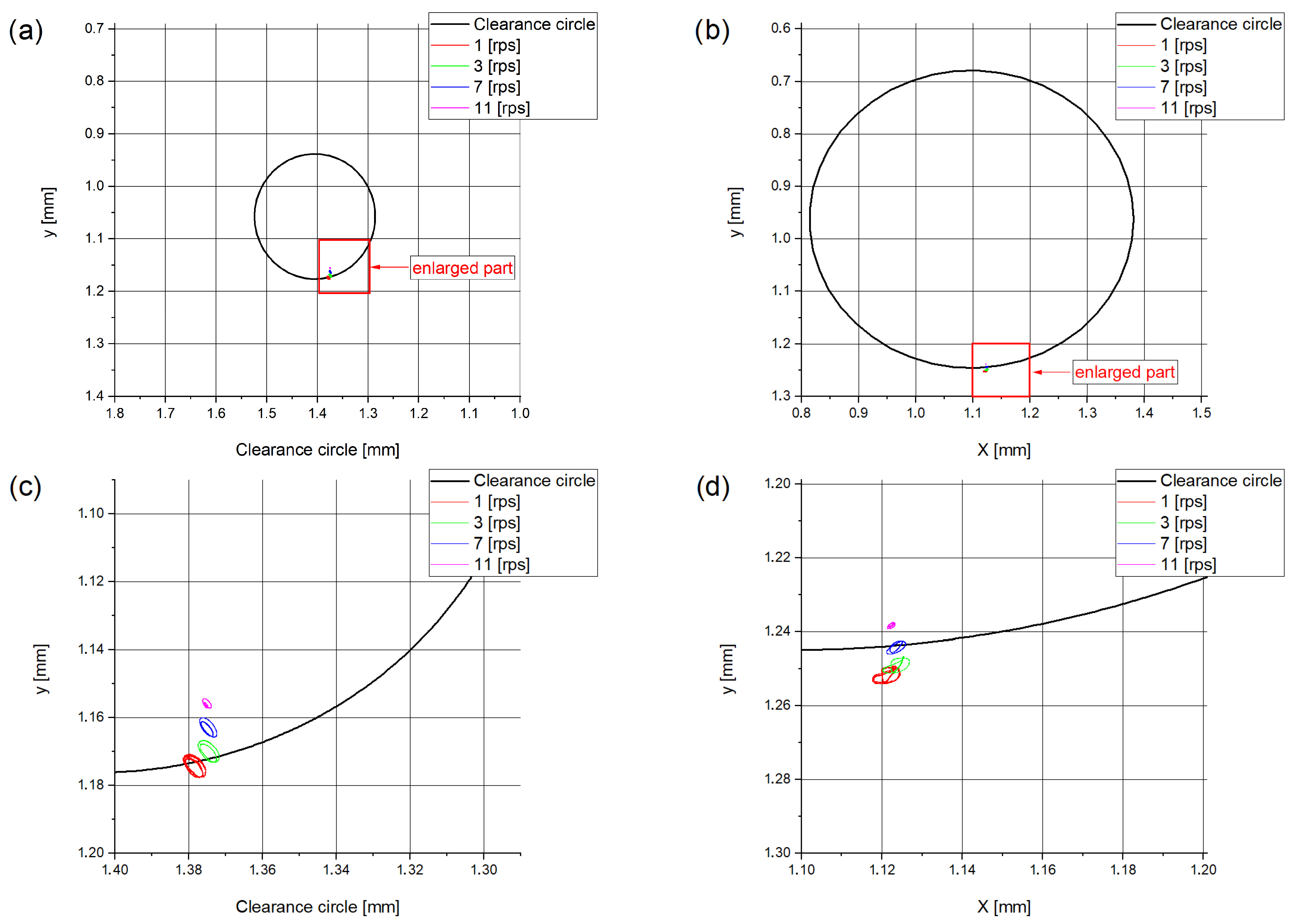
The increase in load means that the orbits are increasingly outside the contact circle, which indicates significant deformation of the bearing bush. It should be noted that for the real object (i.e., the stern bearing of the propeller shaft, the proportion of which, due to applicable regulations [34,35,43], is often L/D = 4), the pressures under normal operating conditions do not usually exceed 0.28 MPa.
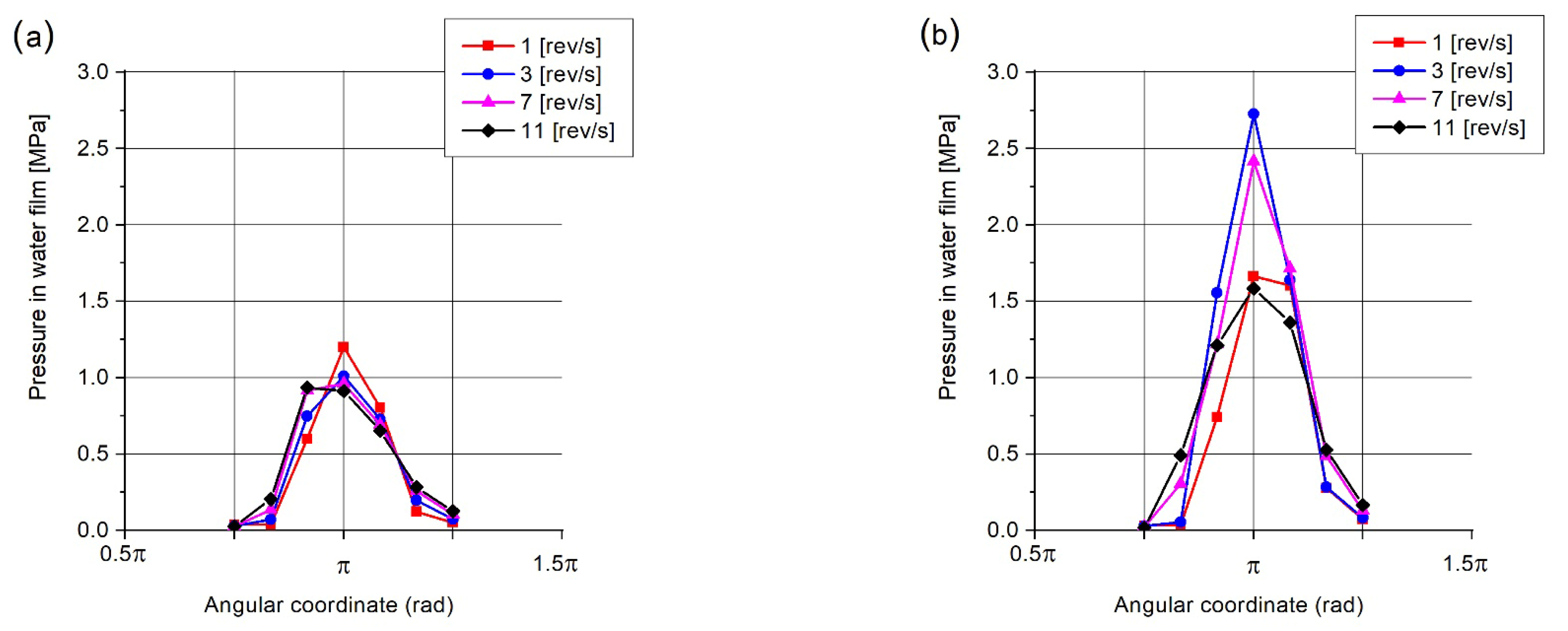
Film pressure distribution was measured with the use of 14 sensors installed in two parallel surfaces (Figure 3). The average pressure value in the film calculated for seven angular positions is shown in the graphs below (Figure 7 and Figure 8).
It can be seen that even at the lowest rotational speed of 1 rev/s (sliding speed 0.31 m/s), fluid film is generated, and that, at least partially, the bearing load is carried by the hydrodynamic lifting force (Figure 7). The influence of the increasing load on pressure distribution for constant speed can be noticed in the figures below (Figure 7).
Figure 6.
Shaft axis trajectories and clearance circles for bearing B, specific load 0.3 MPa: (a) left side of the bearing; (b) right side of the bearing; (c) magnified view of trajectories, left side; (d) magnified view of trajectories, right side.
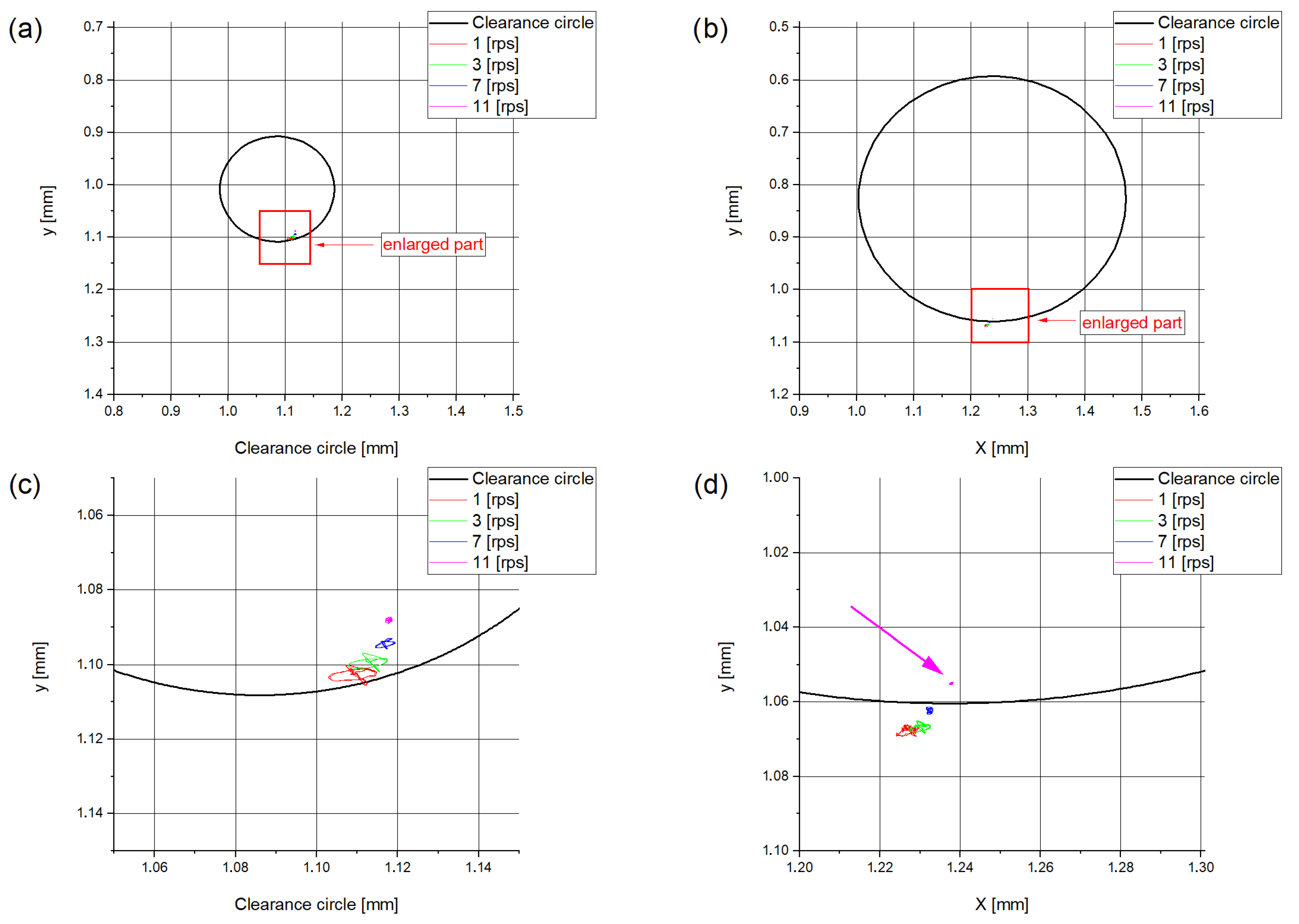
Figure 7.
Film pressure distributions measured in the bearings at rotational speeds of 1–11 rev/s: (a) specific pressure 0.3 MPa; (b) specific pressure 0.6 MPa.
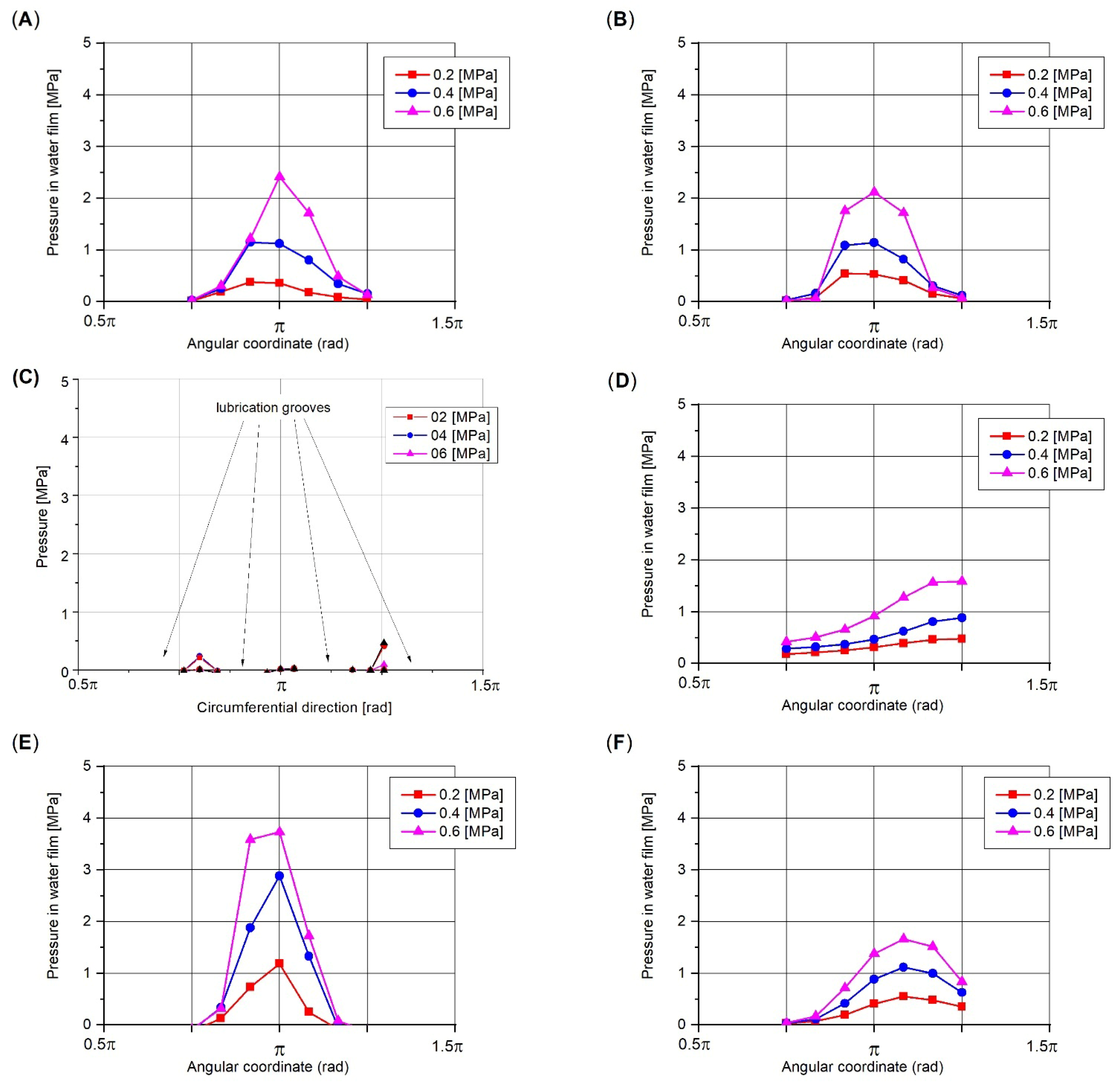
As shown in the orbit graphs (Figure 6), although the shaft speed reaches 11 rpm, the film thickness is small due to the low viscosity of water used as a lubricant. Studying the friction coefficient graphs, it can be assumed that the bearing operates in the fluid friction area because the resistance to motion is low, despite the fact that the film thickness is very small. The graphs of the pressure distribution in the lubricant film for a speed of 11 rpm are shown below.
Figure 8.
Film pressure distributions measured in the bearings at rotational speeds of 11 rev/s, specific pressure 0.2–0.6 MPa; (A) wood—glued, (B) wood—one piece, (C) NBR, (D) polymer, (E) composite, (F) 3-layer.
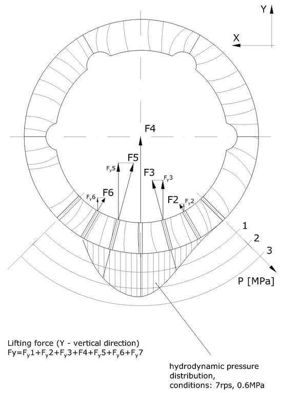
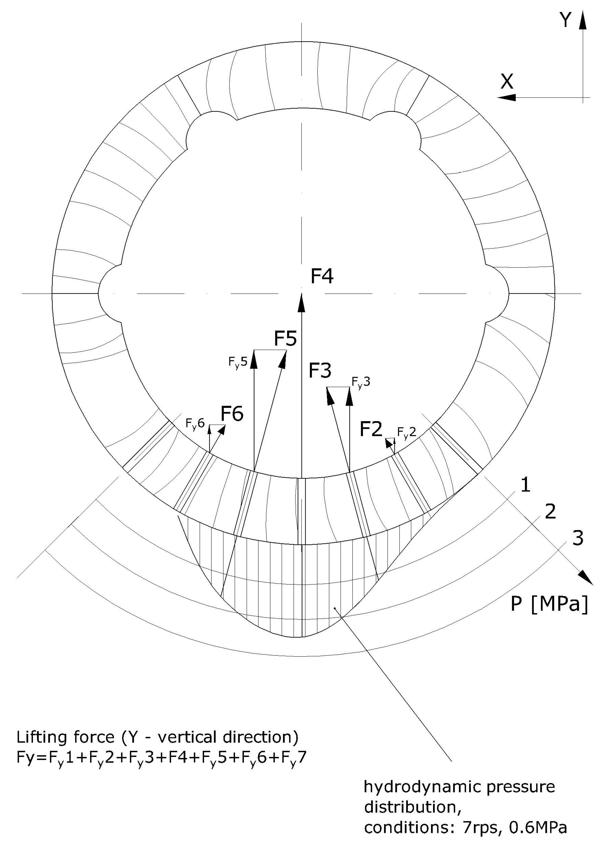
Calculating the lifting force is very useful in such a case. For easier understanding of the applied method, Figure 9 was prepared.
Figure 9.
Lifting force calculation methodology.
Full hydrodynamic lubrication takes place when the acting load (Fla [N]) is carried by the acting hydrodynamic film pressure (Ph [MPa]) in the bearing interspace with limited size (S [mm2]).
Assumptions for L/D = 2 water-lubricated bearings:
- -
- 80% of the bearing length is hydrodynamically effective; 10% of the length (l [mm]) on each side is a pressure drop zone because of side leakage [38].
- -
- It is possible to calculate a local acting hydrodynamic force (Fla [N]) based on measured average pressure (Pm [MPa]) acting on surface length (l [mm]) multiplied by partial arc length (Al [mm])
- -
- For every local acting hydrodynamic force (Fla [N]) the vertical component could be calculated (FYla [N] Figure 9).
Table 3.
Lifting force in bearings—hydrodynamic pressure response.
From Table 3, it can be seen that the load calculated based on film pressure is approximately equal to the bearing load exerted by the test rig load system, which indicates that the bearing is operating in a prevailing hydrodynamic regime. The only test condition under which these two values differed considerably was at the lowest rotational speed and high load (1 rev/s and 0.6 MPa). At this point, approximately 80% of the bearing load is balanced by the film pressure, and the rest is carried by the contact between the bush and shaft [38].
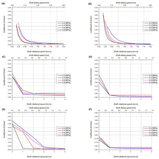
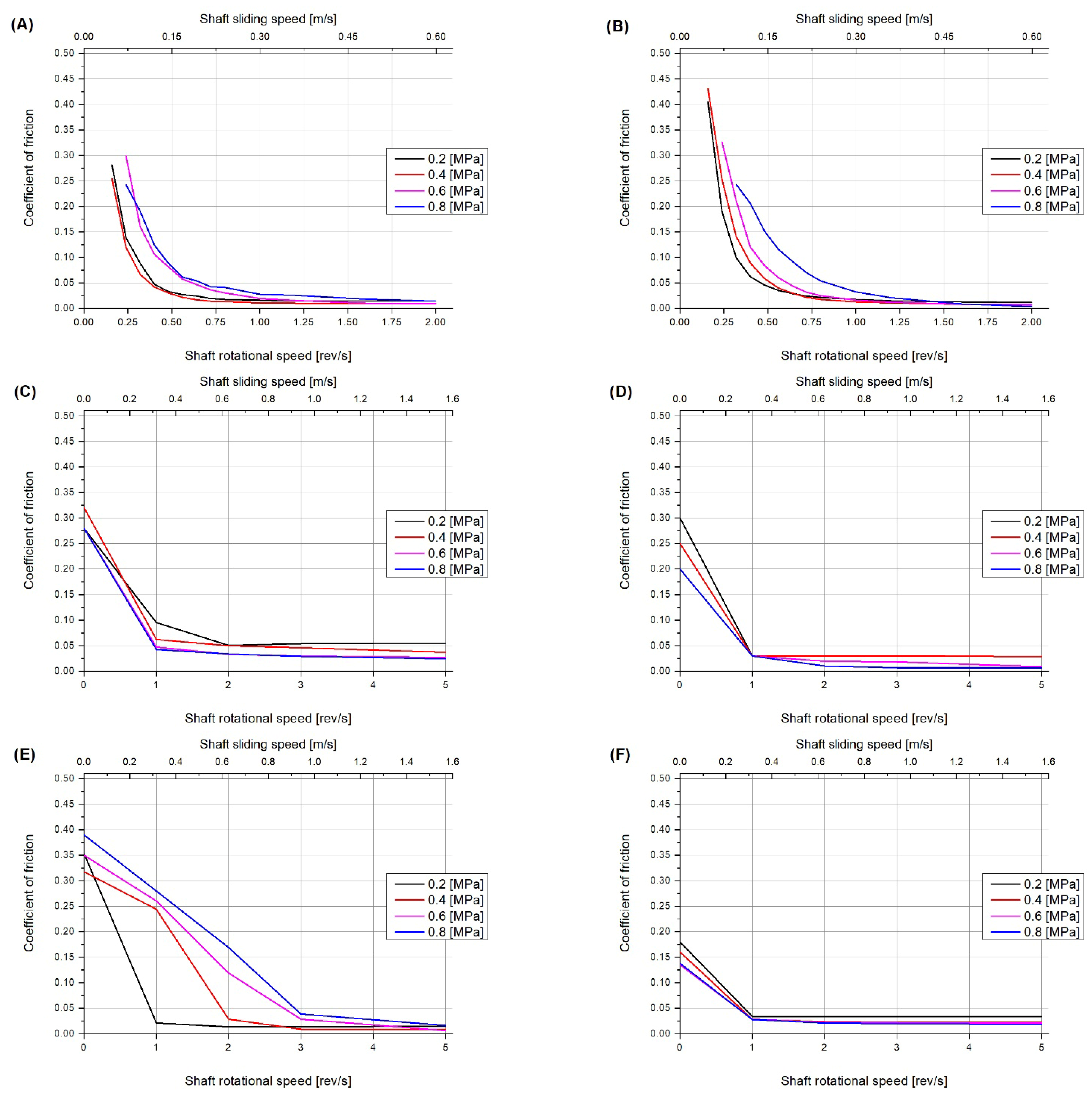
Figure 10 show the friction coefficients measured for the bearings, and it can be seen that for rotational speeds larger than 1 rev/s (sliding speed 0.31 m/s) the friction is very low (i.e., lower than 0.025), whereas at larger speeds there is no difference between the results for bearing A (made from six pieces of lignum vitae wood) and bearing B (a single piece).
Figure 10.
Coefficient of friction for tested bearings (A–F) according to bearing descriptions in Figure 1. (A) wooden—lignum vitae, a six-piece glued bearing bush with transversal wood grains location; (B) wooden—lignum vitae, a one-piece bearing; (C) NBR bearing, (D) polymer bearing, (E) composite bearing, (F) 3-layer bearing.
The measurements of the resistance to motion of the six different bearings presented in Figure 10 may seem similar, but quite significant differences can be seen. When testing the bearings with wooden bushes (Figure 10A,B), a slow-speed drive was installed in the test rig to record the transition between mixed and fluid friction precisely. As expected, it can be seen that increasing the load causes an increase in the friction coefficient and a shift in the transition point. The other bearings (Figure 10C–E) were tested using a drive system that allows for higher rotational speeds of up to 11 rpm. Analyzing the results, it can be concluded that at approximately 1 rpm, the resistance to motion is significantly reduced, and it seems justified to say that the bearings operate in the fluid friction area. Only the measurements of pressure distributions prove that in the bearing with a rubber bush, with numerous lubrication grooves, practically no hydrodynamic pressure is generated. Hence, the bearing operates in the mixed friction regime within the usual range of sliding speeds and pressures in ship applications. Interestingly, this bearing design, often considered outdated because it has been used for almost a hundred years, operates very well in the case of lubrication with water containing solid particles [12]. Positive experience from operation means that this type of bearing is widely used by ship owners.
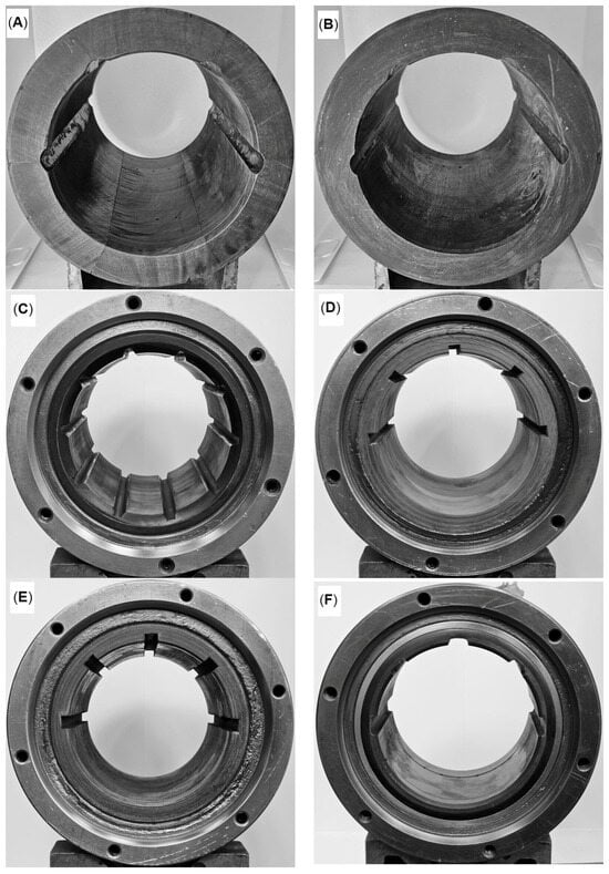
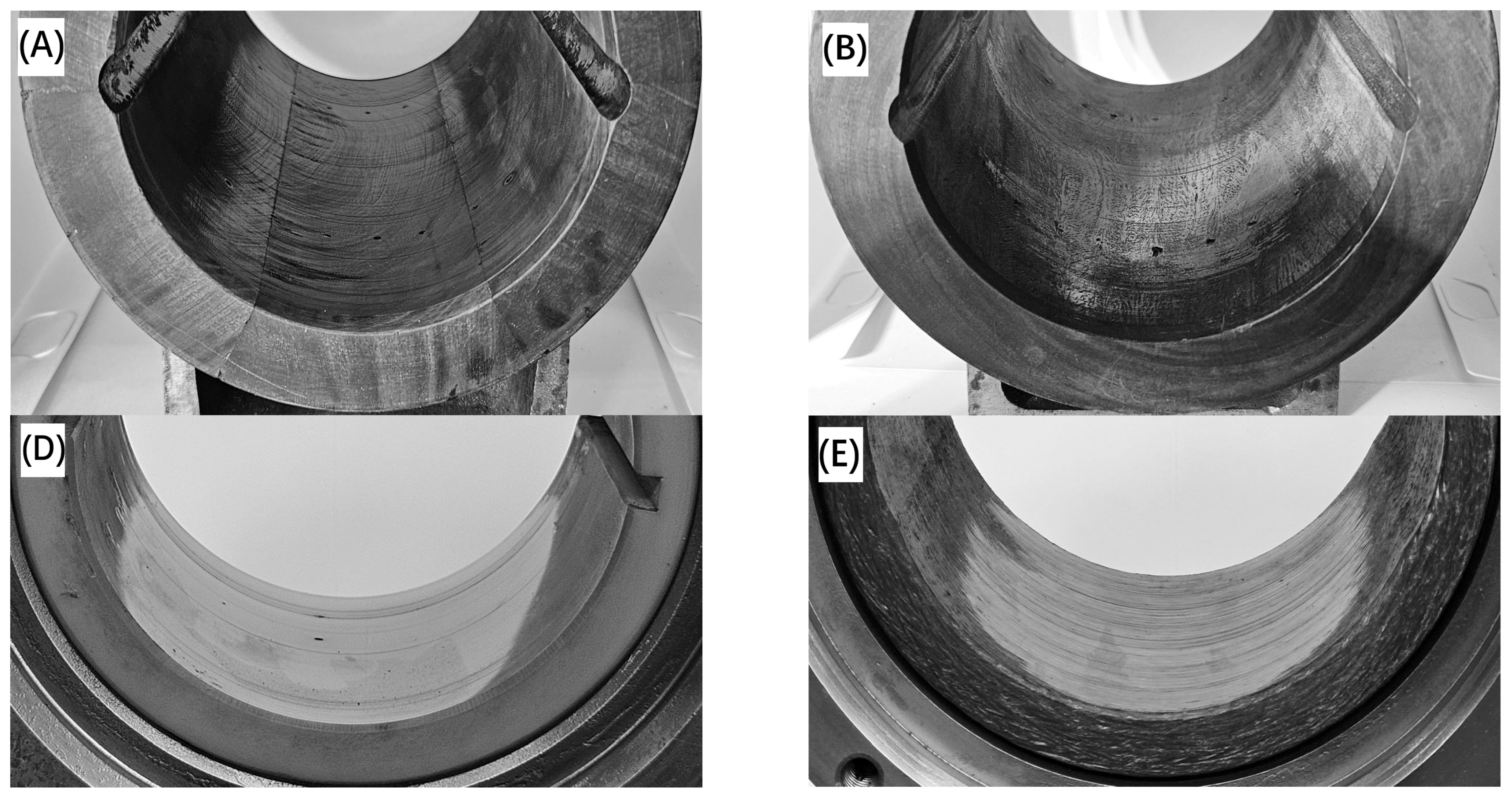
In Figure 11 the bearings after the testing are shown; the sliding surface experienced some wear in the form of minor scratches.
Figure 11.
Selected bearing bushes after tests with visible scratches on sliding surface; (A,B) lignum vitae, (D) polymer, (E) composite.
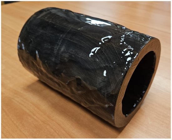
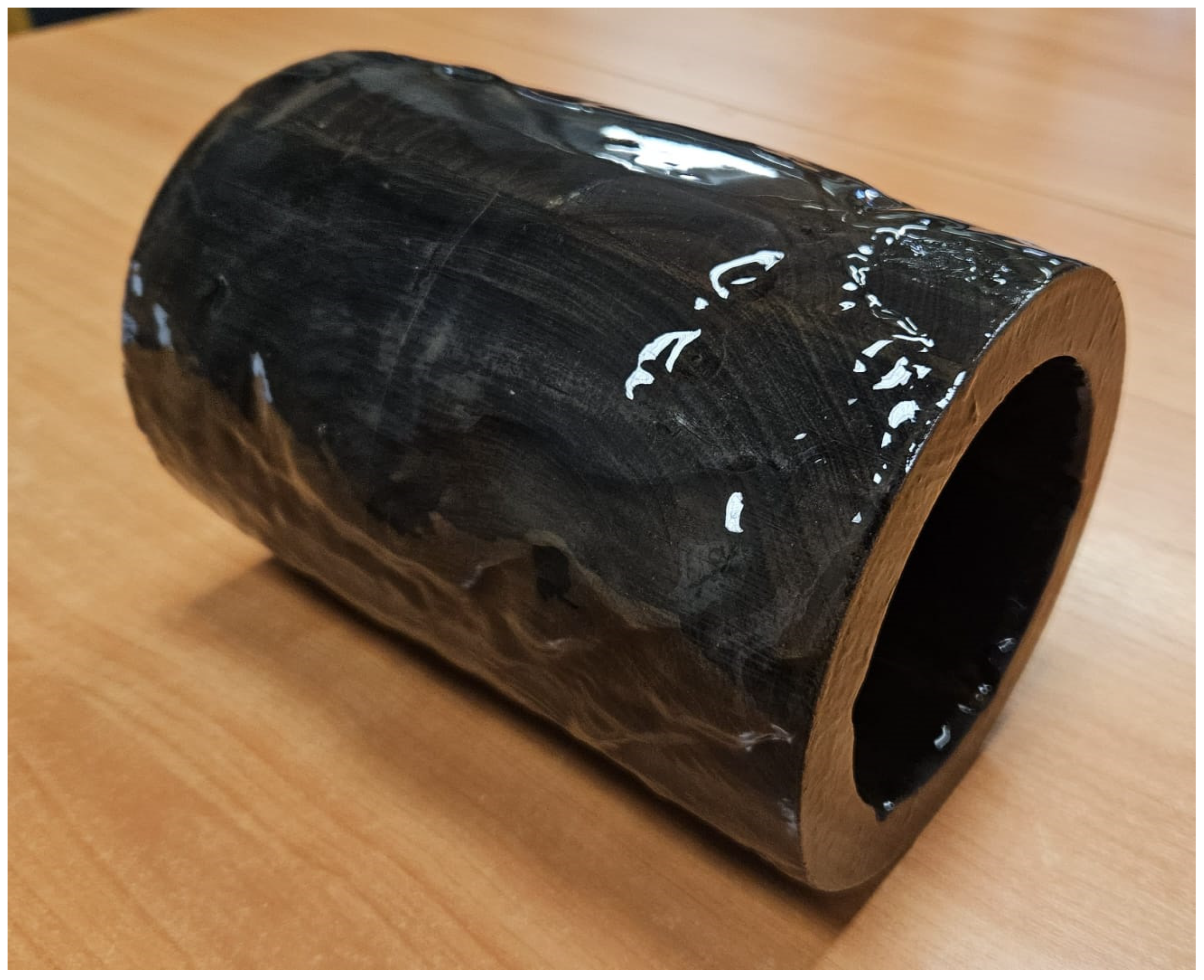
The visible effect of load change on the transition point for the bearing with a composite bush results from the rough surface of the bush, which, despite many hours of running-in, was not ideal. It can be assumed that as the wear process progresses, the sliding surface will eventually smooth and the resistance to movement will decrease. The significant errors in the shape of the bush and the differences in the bearing clearance are worth noting. Despite the shape defects, it was possible to confirm the occurrence of hydrodynamic phenomena in five of the six bearings tested (Table 3). This is important information because it is often anticipated that the geometry of the sliding couple is practically ideal, while in practice, manufacturing limitations, specific assembly methods, or properties of the polymer bush, such as water absorption, make it practically impossible. The lowest starting resistance is demonstrated by the 3-layer bearing with a sliding surface made of PTFE. An interesting phenomenon is shown in Figure 12: after keeping the bushes immersed in water, a unique gel-like substance is formed around the bush, which is slick and well attached to the surface. This is likely to influence the performance of the lignum vitae bearing, as it adheres to the surface quite strongly and is not easy to remove.
Figure 12.
Substance formed on the bearing bush after two months of immersion in water.
4. Conclusions and Future Work
The article presents the results of tests on six different ship propeller shaft bearings. The components were made by known manufacturers from materials with appropriate certificates, allowing for safe installation on a ship. The test results proved that five of the tested bearings operate in a fluid friction regime. That is why the resistance to movement is low, but what is more important, the wear process is slower. The proposed method of verifying the lifting force—hydrodynamic response of the bearing—is useful and efficient, especially when the thickness of the lubricant film is negligible and hard to measure, even in the test rig. Importantly, as the research shows, old materials tested in practice, such as NBR or lignum vitae wood, often demonstrate properties not worse than those of modern plastics. The ship market is very conservative, and the priority is the safety and price of the transport service; so, in times when new restrictions on shipping are being enforced, cheap and simple solutions are sought. The fear of ship owners and bearing manufacturers about the introduction of the PFAS convention causes them to reach for old, proven solutions such as wood (lignum vitae).
This was also the reason why such a bearing was chosen for research and detailed analysis, and to form more detailed conclusions on this bearing type and material. To the best of the authors’ knowledge, no results have previously been published based on such detailed and extensive measurements of realistically sized lignum vitae bearings. Both tested lignum vitae bearings (A and B) operated properly, and there were no major differences between them related to the structure and directionality of the fibers, despite the non-perfect state of the surface, which has the microstructure of wood. In the majority of the tests, the bearing operated under the prevailing conditions of full film lubrication, as evidenced by the pressure in the lubricant film and the resulting bearing load capacity calculated on this basis, which was consistent with the force exerted on the bearing by the station’s loading system despite the presence of very thin films.
The friction coefficients for both bearings were low, with values of less than 0.02 for rotational speeds exceeding 1 rev/s. For speeds above 1 rev/s, this is an evidence for a hydrodynamic friction regime, which was also confirmed by other measurements of pressure and force.
Wear to the bearings was marginal, as shown in Figure 11. Minor scratches can be observed, which appeared despite relatively fine filtration of the lubricating water (5 µm). These scratches indicate that the film is thin, although an evaluation of its thickness is difficult due to deformations of the wooden bush. Due to these shape irregularities, local shaft–bush contacts are possible, as can be seen in the photographs.
In addition to the direct research results, it is worth mentioning that no stick–slip phenomena or high break-away friction forces were observed, unlike many other materials tested in the authors’ laboratory and by other researchers [44,45].
It should be noted that due to the design of lignum vitae bearings, swelling of the bush makes it virtually impossible to precisely control the bearing clearance; this makes it necessary to use a large clearance, which is not favorable in terms of hydrodynamic load-carrying capacity.
In future research, it will be important to understand the role of the gel formed on the bush surface when in contact with water, starting with tests of its chemical/physical nature and tribological properties. Further specimen-scale testing may demonstrate differences between the friction coefficient and dry friction performance, or the wear rates for varying orientations of wood cells in a specimen or for different running-in mechanisms. In this study, no influence of the fibers’ orientation on bearing performance was observed. In future studies, it might also be interesting to observe the influence of extensive wear on the properties of the bearing, as well as the influence of shape irregularities.
As a primary conclusion, it should be stressed that a commercially sized lignum vitae bearing worked very well under operating conditions (a specific load and sliding speed) that were typical of marine main shaft bearings. Once bearings of L/D = 4 are replaced by lignum vitae bearings of L/D = 2 (which is not specifically listed in [46]), the specific load will be less than 0.56 MPa, somewhat less than the value used in this research.
Author Contributions
M.W.: Methodology, Resources, Investigation, Data curation, Validation, Visualization Writing—original draft, Writing—review and editing. W.L.: Methodology, Resources, Investigation, Data curation, Validation, Visualization Writing—original draft, Writing—review and editing. B.S.: Resources, Validation, Writing—review and editing. All authors have read and agreed to the published version of the manuscript.
Funding
This research received no grants from funding agencies in the public, commercial, or not-for-profit sectors. All cost were covered by GdanskTech Tribology Lab—one of the key laboratories of Gdansk University of Technology.
Data Availability Statement
The raw data supporting the conclusions of this article will be made available by the authors on request.
Conflicts of Interest
Author Bob Shortridge was employed by the company Lignum Vitae North America. The remaining authors declare that the research was conducted in the absence of any commercial or financial relationships that could be construed as a potential conflict of interest.
References
- Orndorff, R. Water lubricated rubber bearings, history and new developments. Nav. Eng. J. 1985, 97, 39–52. [Google Scholar] [CrossRef] [Scilit]
- McHugh, J. Albert Kingsbury—His Life and Times. Sound Vib. 2003, 37, 12–20. [Google Scholar]
- Serra, P.; Fancello, G. Towards the IMO’s GHG goals: A critical overview of the perspectives and challenges of the main options for decarbonizing international shipping. Sustainability 2020, 12, 3220. [Google Scholar] [CrossRef] [Scilit]
- Jeong, J.; Seo, S.; You, H.; Chang, D. Comparative analysis of a hybrid propulsion using LNG-LH2complying with regulations on emissions. Int. J. Hydrogen Energy 2018, 43, 3809–3821. [Google Scholar] [CrossRef] [Scilit]
- Yang, J.; Guo, R.; Tian, Y. Hybrid radial basis function/finite element modelling of journal bearing. Tribol. Int. 2008, 41, 1169–1175. [Google Scholar] [CrossRef] [Scilit]
- Inal, O.B.; Charpentier, J.F.; Deniz, C. Hybrid power and propulsion systems for ships: Current status and future challenges. Renew. Sustain. Energy Rev. 2022, 156, 111965. [Google Scholar] [CrossRef] [Scilit]
- Reusser, C.A.; Osses, J.P. Challenges for Zero-Emissions Ship. J. Mar. Sci. Eng. 2021, 9, 1042. [Google Scholar] [CrossRef] [Scilit]
- Litwin, W.; Leśniewski, W.; Kowalski, J. Energy Efficient and Environmentally Friendly Hybrid Conversion of Inland Passenger Vessel. Pol. Marit. Res. 2017, 24, 77–84. [Google Scholar] [CrossRef] [Scilit]
- Kunicka, M.; Wrzask, K.; Litwin, W.; Grygorowicz, M.; Zeratgaar, H. Evaluation of a Small Inland Ferry’s Energy Requirements from the Acceleration Stage of Towing Tank Model Tests. Pol. Marit. Res. 2024, 31, 34–41. [Google Scholar] [CrossRef] [Scilit]
- Barszczewska, A. Experimental Research on Insufficient Water Lubrication of Marine Stern Tube Journal Bearing with Elastic Polymer Bush. Pol. Marit. Res. 2020, 27, 91–102. [Google Scholar] [CrossRef] [Scilit]
- Zuo, R.; Wang, G.; Hu, G.; Zhao, S.; Wei, G. Tribological properties of hydrogenated nitrile rubber in confrontation with hard particles under different axial loads. Tribol. Int. 2021, 153, 106649. [Google Scholar] [CrossRef] [Scilit]
- Litwin, W.; Barszczewska, A.; Piątkowska, E.; Szwoch, I.; Matuszewski, L.; Kahsin, M. Influence of Lubrication Water Contamination by Solid Particles of Mineral Origin on Marine Strut Propeller Shafts Bearings of Ships. Pol. Marit. Res. 2024, 31, 187–196. [Google Scholar] [CrossRef] [Scilit]
- Etkin, D.S. Worldwide Analysis of In-Port Vessel Operational Lubricant Discharges and Leakages. In Proceedings of the Thirty-third AMOP Technical Seminar on Environmental Contamination and Response, Halifax, NS, Canada, 7–9 June 2010; Environment Canada: Ottawa, ON, Canada, 2010; pp. 1–25. [Google Scholar]
- Mang, T. (Ed.) Environmentally Acceptable Lubricants. In Encyclopedia of Lubricants and Lubrication; Springer: Berlin/Heidelberg, Germany, 2014. [Google Scholar] [CrossRef] [Scilit]
- Borras, F.X.; de Rooij, M.B.; Schipper, D.J. Rheological and wetting properties of Environmentally Acceptable Lubricants (EALs) for application in stern tube seals. Lubricants 2018, 6, 100. [Google Scholar] [CrossRef] [Scilit]
- Carter, C.D. Seawater for Propeller Shaft Lubrication in Merchant Ships-Environmental, Operational, Legal and Shipbuilding Considerations. In Proceedings of the World Maritime Technology Conference, Chennai, India, 4–6 December 2024. [Google Scholar]
- Katherine, E.P.; Mcknight, T.; Reade, A. 70 analyte PFAS test method highlights need for expanded testing of PFAS in drinking water. Sci. Total Environ. 2023, 878, 88–100. [Google Scholar] [CrossRef] [Scilit]
- Mohammad, N.E.; Mumtahina, R.; Pervez, M.N.; Khyum, M.M.O.; Liang, Y.; Naddeo, V. Environmental and health impacts of PFAS: Sources, distribution and sustainable management in North Carolina (USA). Sci. Total Environ. 2023, 878, 88–100. [Google Scholar] [CrossRef] [Scilit]
- Kushwaha, M.; Shankar, S.; Goel, D.; Singh, S.; Rahul, J.; Rachna, K.; Singh, J. Microplastics pollution in the marine environment: A review of sources, impacts and mitigation. Mar. Pollut. Bull. 2024, 209, 117109. [Google Scholar] [CrossRef] [Scilit]
- Branagan, L. Water lubricated bearings with lignum vitae: Environmentally sound choices. In Proceedings of the 18th EDF/Pprime Workshop, Palaiseau, France, 10–11 October 2019. [Google Scholar]
- Sydor, M. Drewno W Budowie Maszyn: Historia Najważniejszego Tworzywa; Wydawnictwo Uniwersytetu Przyrodniczego w Poznaniu: Poznan, Poland, 2011. (In Polish) [Google Scholar]
- Dong, C.; Yang, Y.; Yuan, C.; Bai, X.; Guo, Z. Effects of anisotropy of lignum vitae wood on its tribological performances. Compos. Part B Eng. 2022, 228, 109426. [Google Scholar] [CrossRef] [Scilit]
- Wu, Z.; Guo, Z.; Yuan, C.; Huang, Q.; Wang, C.; Zhao, H. Lignum vitae wood-derived composites for high lubricating performance. J. Clean. Prod. 2023, 406, 137086. [Google Scholar] [CrossRef] [Scilit]
- Wu, Y.; Dong, C.; Bai, X.; Yuan, C.; Zhang, X. A novel green and low friction composite reinforced by lignum vitae chips. Polym. Test. 2022, 115, 107768. [Google Scholar] [CrossRef] [Scilit]
- Wang, H.; Liu, Z.; Zou, L.; Yang, J. Influence of both friction and wear on the vibration of marine water lubricated rubber bearing. Wear 2017, 376–377, 920–930. [Google Scholar] [CrossRef] [Scilit]
- Guo, Z.; Yuan, C.; Liu, A.; Jiang, S. Study on tribological properties of novel biomimetic material for water-lubricated stern tube bearing. Wear 2017, 376–377, 911–919. [Google Scholar] [CrossRef] [Scilit]
- Roldo, L.; Komar, I.; Vulić, N. Design and materials selection for environmentally friendly ship propulsion system. Stroj. Vestn./J. Mech. Eng. 2013, 59, 25–31. [Google Scholar] [CrossRef] [Scilit]
- Zhang, Y.; Chen, K.; Jiang, D.P. CFD analysis of the lateral loads of a propeller in oblique flow. Ocean Eng. 2020, 202, 107153. [Google Scholar] [CrossRef] [Scilit]
- Testa, C.; Greco, L.; Bosschers, J. Marine propeller shaft loading analysis in moderate oblique-flow conditions. Ocean Eng. 2022, 262, 112199. [Google Scholar] [CrossRef] [Scilit]
- Xie, H.; Dai, X.; Liu, F.; Liu, X. Experimental study on the slamming pressure distribution of a 3D stern model entering water with pitch angles. Ocean Eng. 2024, 291, 116404. [Google Scholar] [CrossRef] [Scilit]
- Vartdal, B.J.; Gjestland, T.; Arvidsen, T.I. Lateral Propeller Forces and their Effects on Shaft Bearings. In Proceedings of the First International Symposium on Marine Propulsors, Trondheim, Norway, 22–24 June 2009. [Google Scholar]
- Ha, J.; Park, J.; Park, G.; Kim, J.; Kim, J.; Seo, J.; Rhee, S.H. Experimental study on the propulsion performance of a partially submerged propeller. Int. J. Nav. Archit. Ocean Eng. 2023, 15, 100516. [Google Scholar] [CrossRef] [Scilit]
- Li, R.; Ouyang, W.; Liu, Q.; Jin, Y.; Yang, J. Dynamic bearing characteristics of the ship stern shaft-bearing system with wave impact. Ocean Eng. 2024, 312, 119020. [Google Scholar] [CrossRef] [Scilit]
- Komar, I.; Vulić, N.; Roldo, L. Hydrodynamic and elastohydrodynamic lubrication model to verify the performance of marine propulsion shafting. Trans. Famena 2013, 37, 15–27. [Google Scholar]
- Chen, Z.; Wang, J.; Li, R.; Liu, Y. A novel 4-DOF marine stern bearing support model considering discrete distribution effects. Ocean Eng. 2024, 312, 119072. [Google Scholar] [CrossRef] [Scilit]
- He, T.; Zou, D.; Lu, X.; Guo, Y.; Wang, Z.; Li, W. Mixed-lubrication analysis of marine stern tube bearing considering bending deformation of stern shaft and cavitation. Tribol. Int. 2014, 73, 108–116. [Google Scholar] [CrossRef] [Scilit]
- Żochowski, T.; Litwin, W. Innovative 3D Measuring Technique for Identifying Geometrical Imperfections and Wear in Small Marine Stern Tube Liners. Pol. Marit. Res. 2025, 32, 129–136. [Google Scholar] [CrossRef] [Scilit]
- Wang, Y.; Shi, X.; Zhang, L. Experimental and numerical study on water-lubricated rubber bearings. Ind. Lubr. Tribol. Exp. 2014, 2, 282–288. [Google Scholar] [CrossRef] [Scilit]
- Litwin, W. Water lubricated marine stern tube bearings—Attempt at estimating hydrodynamic capacity. In Proceedings of the ASME/STLE International Joint Tribology Conference 2009, IJTC2009, Memphis, TN, USA. 19–21 October 2009; American Society of Mechanical Engineers (ASME): New York, NY, USA, 2010. [Google Scholar] [CrossRef] [Scilit]
- Chun, S.M.; Khonsari, M.M. Wear simulation for the journal bearings operating under aligned shaft and steady load during start-up and coast-down conditions. Tribol. Int. 2016, 97, 440–466. [Google Scholar] [CrossRef] [Scilit]
- Xie, Z.; Shen, N.; Zhu, W.; Tian, W.; Hao, L. Theoretical and experimental investigation on the influences of misalignment on the lubrication performances and lubrication regimes transition of water lubricated bearing. Mech. Syst. Signal Process. 2021, 149, 107211. [Google Scholar] [CrossRef] [Scilit]
- Litwin, W. Experimental research on marine oil-lubricated stern tube bearing. J. Eng. Tribol. 2019, 233, 1773–1781. [Google Scholar] [CrossRef] [Scilit]
- DNV-GL. CLASS PROGRAMME, Type Approval, DNVGL-CP-0081—Synthetic Bearing Bushing Materials; Det Norske Veritas Germanischer Lloyd: Høvik, Norway, 2016. [Google Scholar]
- Golchin, A.; Simmons, G.F.; Glavatskih, S.B. Break-away friction of PTFE materials in lubricated conditions. Tribol. Int. 2012, 48, 54–62. [Google Scholar] [CrossRef] [Scilit]
- Han, H.S.; Lee, K.H. Experimental verification of the mechanism on stick-slip nonlinear friction induced vibration and its evaluation method in water-lubricated stern tube bearing. Ocean Eng. 2019, 182, 147–161. [Google Scholar] [CrossRef] [Scilit]
- Cowper, D.N.; Kolomojcev, A.; Danahy, K.; Happe, J. USCG Polar Class aft sterntube bearing design modifications. In Proceedings of the 7th International Conference and Exhibition on Performance of Ships and Structures in Ice, ICETECH 2006, Banff, AB, Canada, 16–19 July 2006; Bercha Group: Calgary, AB, Canada, 2006; pp. 218–224. [Google Scholar] [CrossRef] [Scilit]

Disclaimer/Publisher’s Note: The statements, opinions and data contained in all publications are solely those of the individual author(s) and contributor(s) and not of MDPI and/or the editor(s). MDPI and/or the editor(s) disclaim responsibility for any injury to people or property resulting from any ideas, methods, instructions or products referred to in the content. |
© 2026 by the authors. Licensee MDPI, Basel, Switzerland. This article is an open access article distributed under the terms and conditions of the Creative Commons Attribution (CC BY) license.