


Abstract
Ti-6Al-4V alloy is widely used in aerospace, biomedical, and engineering applications because of its high specific strength, corrosion resistance, and biocompatibility. However, its relatively low surface hardness and poor wear resistance limit its use under sliding-contact conditions. In this study, Ti-6Al-4V specimens were subjected to low-pressure gas nitriding at 950 °C for 60, 100, and 130 min to investigate the effects of short nitriding time on microstructure, hardness, and tribological behavior. The nitrided layers were characterized by scanning electron microscopy (SEM), energy-dispersive X-ray spectroscopy (EDS), electron backscatter diffraction (EBSD), and X-ray diffraction (XRD). Cross-sectional microhardness, Rockwell C indentation, surface roughness, and dry sliding wear tests according to ASTM G99 were also evaluated. Low-pressure gas nitriding produced a graded surface region consisting mainly of a TiN/Ti2N compound layer and an α-Ti(N) diffusion zone. Increasing nitriding time promoted nitrogen penetration and development of the nitrided region. The N100 specimen exhibited the highest near-surface microhardness of approximately 550 HV0.025, whereas N130 showed a lower value of approximately 490 HV0.025. Despite its lower near-surface hardness than N100, N130 exhibited the lowest mean wear loss among the nitrided specimens, with a gravimetrically estimated wear volume of 0.722 ± 0.060 mm3 and a specific wear rate of (5.99 ± 0.50) × 10−4 mm3/(N·m). After correction using the adjacent unworn surfaces as references, the maximum wear depths in representative profiles were approximately 49.2, 47.8, and 23.3 μm for N60, N100, and N130, respectively. These depths exceeded the corresponding TiN/Ti2N compound-layer thicknesses of approximately 6–10 μm, indicating local penetration through the outer compound layer in all three conditions during prolonged sliding under a normal load of 4 N. The wear response did not follow the same trend as near-surface hardness, compound-layer thickness, or initial surface roughness, indicating that no single parameter alone governed material removal. Instead, the results suggest that the overall response of the graded nitrided region, including penetration depth, layer integrity, surface condition, and subsurface mechanical support, collectively influenced the tribological behavior. SEM and EDS observations were consistent with abrasive wear features accompanied by local adhesion, tribo-oxidation, delamination, and third-body interactions, although the relative contribution of each mechanism could not be determined conclusively. Under the present test condition, the untreated specimen exhibited the lowest overall wear volume, whereas N130 showed the lowest material loss among the nitrided specimens. The formation of an effective nitrided region within 60–130 min at 950 °C demonstrates the feasibility of short-duration LPGN and suggests potential reductions in processing time and thermal exposure.
1. Introduction
Ti-6Al-4V is a widely used α + β titanium alloy because of its high specific strength, good corrosion resistance, fatigue resistance, and biocompatibility. It is commonly used in aerospace structures, turbine and compressor components, fasteners, chemical processing equipment, and biomedical devices [1,2,3,4,5]. However, its relatively low surface hardness and poor wear resistance remain major concerns in applications involving repeated sliding contact. The strong chemical affinity of titanium toward counterface materials can lead to adhesion, material transfer, unstable friction, plastic deformation, and surface damage [6,7,8,9]. Improving the surface hardness and wear resistance of Ti-6Al-4V without seriously affecting the substrate is therefore important for tribological applications.
Several surface modification methods have been applied to titanium alloys, including physical vapor deposition (PVD), chemical vapor deposition (CVD), ion implantation, plasma nitriding, laser nitriding, thermal oxidation, and gas nitriding [10,11,12,13,14,15,16]. Among these methods, nitriding is widely used because nitrogen reacts readily with titanium and forms hard nitride phases. During treatment, nitrogen diffuses from the surface into the substrate and produces a modified layer that generally contains TiN, Ti2N, and a nitrogen-enriched α-Ti(N) diffusion zone [17,18,19,20]. TiN and Ti2N increase surface hardness, while the diffusion zone provides support beneath the hardened layer.
Low-pressure gas nitriding (LPGN) offers good control of treatment temperature, nitrogen atmosphere, pressure, and holding time. The low-pressure environment also helps reduce oxygen contamination during treatment. Unlike deposited coatings, LPGN modifies the surface through nitrogen diffusion into the substrate, which gives a more gradual transition in properties between the hardened surface and the base material [21,22,23,24]. This is useful for titanium components exposed to friction and wear.
One drawback of nitriding is the relatively long treatment time often required to obtain sufficient nitrogen diffusion and surface hardening. Long holding times increase processing time and energy use and may also cause unwanted microstructural changes in Ti-6Al-4V. Reducing the nitriding time while retaining sufficient hardness and wear resistance would therefore be beneficial from both processing and energy-saving viewpoints. A shorter treatment cycle may also improve the overall efficiency of the surface modification process.
Nitriding behavior depends mainly on treatment temperature and holding time. Increasing either parameter generally promotes nitrogen diffusion, nitride formation, and growth of the modified layer [25,26,27,28]. However, longer treatment does not always lead to better tribological performance. When Ti-6Al-4V is treated near its β-transus temperature, grain growth, lamellar transformation, surface roughening, residual stress, and increased brittleness may occur [29,30,31,32]. These changes can reduce the integrity of the nitrided layer and increase the risk of cracking or delamination during sliding. For this reason, the nitriding condition must provide sufficient nitrogen penetration without excessive thermal exposure.
Previous studies have investigated plasma nitriding, ion nitriding, laser-assisted nitriding, and gas nitriding of Ti-6Al-4V. Ongtrakulkij et al. [21] reported that plasma nitriding temperature and duration affected nitrogen diffusion, residual stress, and hardness. Hosseini and Ahmadi [25] also demonstrated the effects of treatment temperature and time on surface morphology, phase formation, and hardness. Januszewicz and Klimek [33] investigated the nitriding of titanium and Ti-6Al-4V in ammonia gas under low pressure, while Kang et al. [34] examined the tribological behavior of titanium alloy subjected to combined nitriding and surface texturing. Other studies have reported improvements in the hardness and wear resistance of Ti-6Al-4V through the formation of TiN/Ti2N compound layers [35,36,37]. However, many reported treatments involve holding times of several hours, and their outcomes depend on the treatment atmosphere, temperature, and initial surface condition. Further investigation of short-duration LPGN near the β-transus temperature is therefore needed to clarify the relationships among nitriding time, hardness gradient, modified-layer development, and sliding wear behavior.
The wear response of nitrided Ti-6Al-4V depends on the mechanical properties and integrity of the modified region, including the support provided by the underlying diffusion zone. A hard surface layer may undergo cracking or removal if the underlying material cannot adequately support the sliding contact. Consequently, the highest near-surface hardness does not necessarily correspond to the lowest wear loss. Phase constitution, hardness distribution, layer thickness and integrity, and wear-track characteristics should therefore be evaluated together [38,39,40,41]. Sliding conditions must also be considered. Straffelini and Molinari [42] showed that the dry sliding wear behavior of Ti-6Al-4V varied with the counterface material, applied load, and sliding velocity, including transitions between oxidative and delamination wear. Although their study did not directly address the present nitrided layers, it demonstrates the importance of interpreting wear mechanisms within the specific contact conditions employed. Accordingly, the present study evaluates the combined microstructural and mechanical response of the nitrided region under a fixed sliding condition, rather than using hardness alone to rank wear resistance.
Our previous study investigated low-pressure gas nitriding followed by oxidation and showed that a TiO2/TiN/Ti2N duplex structure affected the tribological behavior of Ti-6Al-4V [30]. In that study, the nitriding condition was fixed at 1000 °C for 100 min, and the main variable was the oxidation temperature. The effect of nitriding time itself was not examined in detail. The present work therefore focuses on low-pressure gas nitriding without subsequent oxidation.
In this study, Ti-6Al-4V alloy was nitrided at 950 °C for 60, 100, and 130 min. The microstructure, elemental distribution, phase constitution, hardness gradient, and layer integrity were examined using SEM, EDS, EBSD, XRD, microhardness measurements, and Rockwell C indentation. Dry sliding wear tests were performed according to ASTM G99 [43] to evaluate the coefficient of friction, wear-track morphology, material removal, and wear mechanisms. The aim was to determine how short nitriding times affect the development of the TiN/Ti2N layer and the tribological performance of Ti-6Al-4V. The difference between the condition with the highest near-surface hardness and that with the best wear resistance was also examined. In addition, the study evaluates whether an effective nitrided layer can be obtained within a shorter treatment period, with the aim of reducing processing time and thermal energy demand.
2. Materials and Methods
2.1. Material Preparation and Low-Pressure Gas Nitriding
Commercial Ti-6Al-4V alloy (α + β phase, composition in Table 1) was cut into specimens (35 mm × 35 mm × 5 mm) using wire electrical discharge machining. The specimens were ground with SiC abrasive papers up to #1200 grit, polished to a mirror finish using a 0.5 μm alumina suspension, and ultrasonically cleaned in ethanol before nitriding.
Table 1.
Elemental Composition of Ti-6Al-4V Titanium Alloy Specimen (wt%).
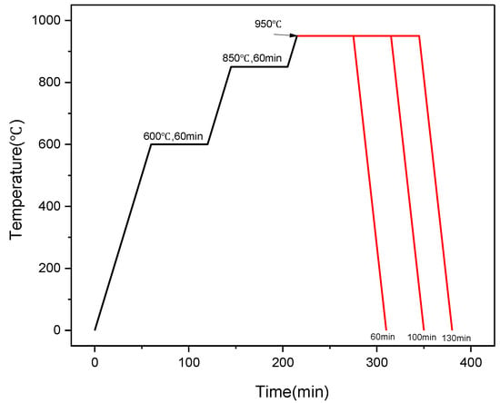
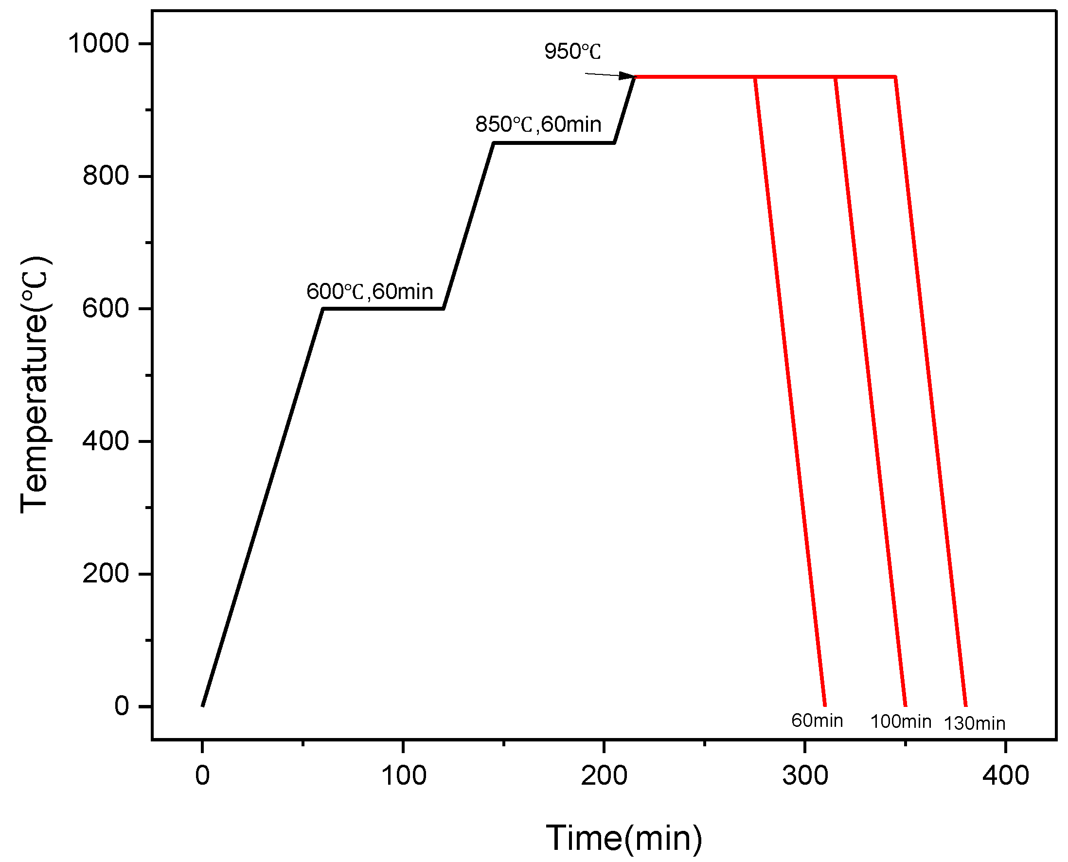
The pretreated specimens were placed in the nitriding chamber, which was first evacuated to approximately 1 × 10⁻² Pa to minimize oxidation. According to the temperature–time profile shown in Figure 1, the furnace temperature was increased stepwise to 950 °C. High-purity nitrogen was then introduced into the chamber at a pressure of 270 kPa, and the specimens were nitrided at 950 °C for 60, 100, and 130 min. After the specified holding period, the nitrogen pressure was increased to 275 kPa for cooling, and the specimens were cooled at a controlled rate of approximately 2 °C/min. The specimens treated for 60, 100, and 130 min are hereafter designated as N60, N100, and N130, respectively.
Figure 1.
Temperature–time profile of the low-pressure gas nitriding process at 950 °C for different holding times.
2.2. Microstructural and Elemental Analyses
For cross-sectional examination, the nitrided specimens were sectioned, mounted, ground, and polished to a mirror finish. The polished cross sections were etched using a mixture of TS100 titanium alloy etchant and 35% H2O2 at a volume ratio of 2:1. Etching was carried out at 45–55 °C for approximately 3 min 45 s to 4 min under ultrasonic agitation, followed by cleaning with ethanol.
Surface and cross-sectional microstructures were examined using a field-emission scanning electron microscope (FE-SEM; SU8600, Hitachi High-Tech, Tokyo, Japan) operated at an accelerating voltage of 15 kV with an aperture of 90 μm. Surface observations were used to examine changes in particle morphology, surface irregularities, pores, and microcracks after nitriding. Cross-sectional images were used to characterize the morphology and continuity of the nitrided layer.
Elemental distributions across the nitrided region were examined by Energy-dispersive X-ray spectroscopy (EDS) mapping. The distributions of Ti, Al, V, and N were recorded to determine the nitrogen-rich region and changes in elemental distribution from the surface toward the substrate.
Electron backscatter diffraction (EBSD) was performed on the specimen nitrided for 60 min to examine the local phase distribution and microstructural features within the modified region. The distributions of α-Ti, β-Ti, TiN, and Ti2N were analyzed, with particular attention to the lamellar structure and phase-boundary regions.
2.3. X-Ray Diffraction Analysis
The phase constituents of the untreated and nitrided surfaces were analyzed using an X-ray diffractometer (D8 Advance, Bruker, Ettlingen, Germany) with Cu Kα radiation. The diffraction patterns were recorded over a 2θ range of 30–90° at a scanning rate of 4°/min. The operating voltage and tube current were 30 kV and 10 mA, respectively.
The diffraction peaks were identified by comparison with standard JCPDS reference data. Particular attention was given to α-Ti, β-Ti, TiN, and Ti2N, together with other phases detected after nitriding. The diffraction patterns obtained for the 60, 100, and 130 min treatments were compared to examine changes in phase constitution with nitriding time.
The calculated values are reported as crystallite sizes rather than physical grain sizes because the Scherrer equation estimates the coherent diffraction-domain size from XRD peak broadening. Instrumental broadening and lattice-strain effects were not separately corrected in the present analysis; therefore, the calculated crystallite sizes were used mainly for comparison among specimens nitrided under different holding times.
2.4. Indentation and Cross-Sectional Microhardness Tests
The integrity of the nitrided layer was evaluated by Rockwell C indentation using a diamond cone indenter under a load of 150 kgf. After indentation, the regions surrounding the indentation marks were examined by optical microscopy under dark-field illumination. Cracking, spallation, and delamination around the indentation were evaluated according to the VDI 3198 classification [44], ranging from HF1 to HF6.
Cross-sectional microhardness was measured using a micro-Vickers hardness tester (FM-810, Future-Tech Corp., Kanagawa, Japan) under a load of 25 gf with a dwell time of 12 s. Measurements were started at a depth of approximately 10 μm below the surface and continued to a depth of 150 μm at intervals of 10 μm. Four indentations were made at each depth, and the average value was used to construct the hardness-depth profile. The substrate hardness was additionally measured at approximately 2.5 mm below the surface.
2.5. Sliding Wear Test
Dry sliding wear tests were carried out using a ball-on-disk configuration according to ASTM G99. For each nitriding condition, three wear tests were performed at spatially separated locations on the same specimen under identical testing conditions. A tungsten carbide (WC) ball with a diameter of 6 mm and a hardness of HRA 90 ± 1 was used as the counterbody. The normal load was fixed at 4 N, and the disk was rotated at 200 rpm for 6000 revolutions with a wear-track radius of 8 mm, corresponding to a sliding speed of approximately 0.17 m/s and a total sliding distance of 301.6 m.
The coefficient of friction (COF) was continuously recorded during each test. For each nitriding condition, the three COF datasets obtained from the different wear locations were used to calculate the mean friction response. The mean COF and corresponding standard deviation were also calculated from the three wear tests.
The specimen mass was measured before and after each wear test using an analytical balance, and the gravimetric mass loss was determined from the difference between the pre-wear and post-wear masses. The reported mass values, mass loss, and COF are expressed as mean ± standard deviation based on the three spatially separated wear locations.
Because the three wear tests were performed at different locations on the same specimen rather than on independently prepared replicate specimens, the reported standard deviations represent within-specimen spatial variation and should not be interpreted as specimen-to-specimen reproducibility. Accordingly, the results are used primarily for comparative evaluation of the tribological response among the N60, N100, and N130 conditions.
Before wear testing, the areal surface roughness (Sa) of the untreated and nitrided specimens was measured using a KEYENCE laser scanning microscope with a 50× objective lens (KEYENCE CORPORATION, Osaka, Japan). The untreated specimen was ground and polished using the same pre-treatment procedure as the nitrided specimens but was not subjected to nitriding. Multiple roughness measurements were performed at different surface locations, and the mean values and standard deviations were calculated.
2.6. Wear-Track Characterization
After the wear tests, the wear tracks were examined by SEM to identify the main surface damage features. Grooves, scratches, wear debris, cracks, plastic deformation, and local delamination were recorded at selected regions of the wear tracks.
EDS mapping was performed on the worn surfaces to examine the distributions of Ti, Al, V, N, O, and W. The N distribution was used to assess the remaining nitrided region, while O and W were examined to identify tribo-oxidation and material transfer from the WC counterbody, respectively.
The three-dimensional morphology and cross-sectional profiles of the wear tracks were measured using a KEYENCE laser scanning microscope with a 50× objective lens. Measurements were made after calibration and focusing under the same observation conditions. Wear-track width, maximum wear depth and cross-sectional profile were obtained to compare the amount and morphology of material removal among the N60, N100, and N130 specimens.
3. Results
3.1. Microstructure and Elemental Distribution
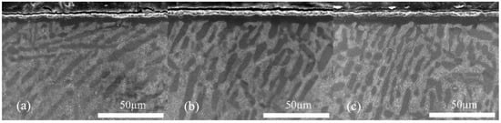
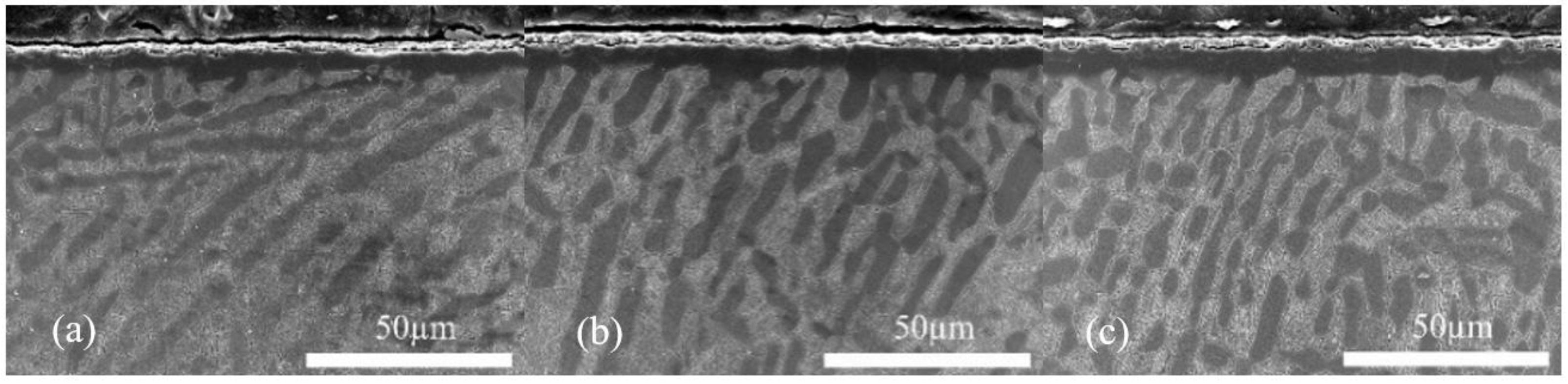
Figure 2 shows the cross-sectional SEM images of Ti-6Al-4V specimens nitrided at 950 °C for 60, 100, and 130 min. A continuous modified layer was observed near the surface for all three conditions. The nitrided region consisted of an outer compound layer and an underlying diffusion zone, followed by the substrate. Based on the phase and elemental analyses discussed below, these regions were associated mainly with TiN/Ti2N and nitrogen-enriched α-Ti(N), respectively.
Figure 2.
Cross-sectional SEM micrographs showing the nitrided layers of Ti-6Al-4V alloy treated at 950 °C for: (a) 60 min, (b) 100 min, and (c) 130 min.
After 60 min of nitriding, a distinct surface-modified region had already formed, although its penetration into the substrate was relatively limited. Increasing the holding time to 100 min produced a more developed surface layer and diffusion zone with a relatively uniform interface. After 130 min, the modified region became more pronounced and showed a more continuous layered morphology. The increase in layer depth with treatment time is consistent with continued inward diffusion of nitrogen. However, the change in thickness became less pronounced at longer holding times, suggesting that further layer growth was increasingly controlled by nitrogen diffusion through the previously formed nitrided region [4,5,13].
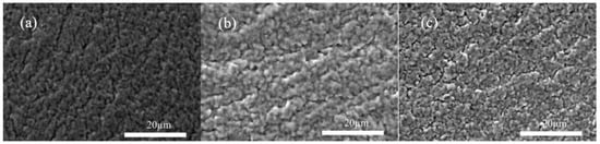
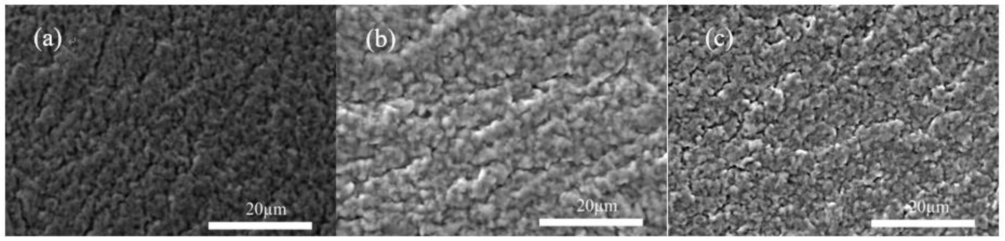
Figure 3 presents the surface morphologies of the specimens after different nitriding times. The surface of the N60 specimen consisted mainly of fine and relatively uniform particles. After 100 min, the surface features became larger and the topography was more pronounced. Further increasing the nitriding time to 130 min resulted in coarser surface features, together with locally irregular regions, pores, and small cracks. These observations indicate that prolonged nitriding promoted the growth of the surface nitride layer but also increased surface coarsening. The local defects observed after 130 min may be associated with prolonged exposure at 950 °C, nitride growth, and the development of internal stresses within the modified surface [14,15,16]. Longer nitriding times promoted layer development, although surface coarsening became more evident after 130 min.
Figure 3.
SEM surface morphologies of Ti-6Al-4V alloy nitrided at 950 °C for different holding times: (a) 60 min, (b) 100 min, and (c) 130 min.
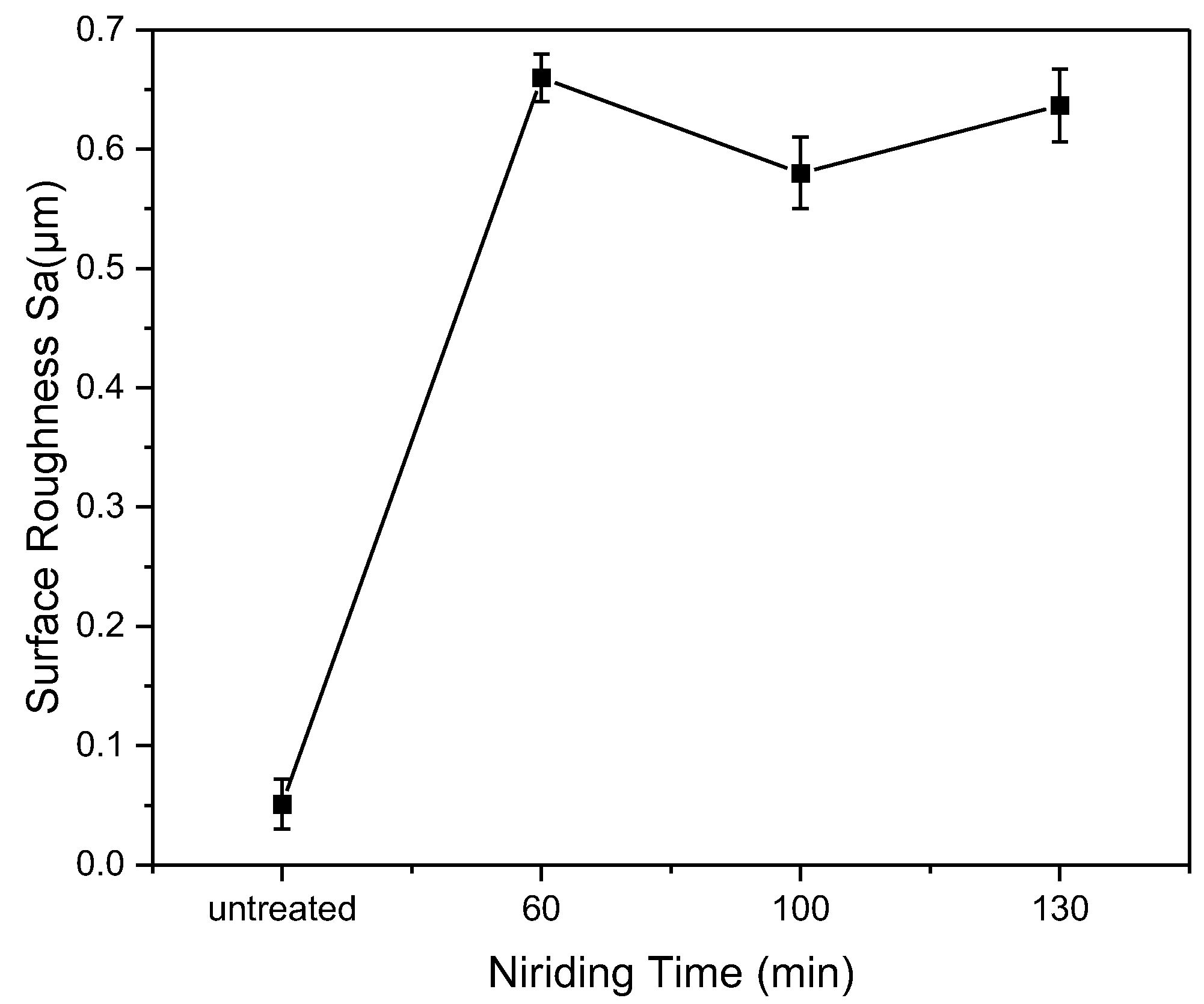
Although the N130 specimen exhibited coarser surface features, local pores, and small cracks before wear testing, these localized surface defects did not correspond directly to greater overall material loss during sliding. The initial Sa of N130 was approximately 0.64 μm, which was only slightly higher than that of N100 (~0.58 μm) and comparable to that of N60 (~0.66 μm). Therefore, the lower wear loss of N130 cannot be attributed to a smoother initial surface.
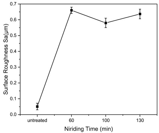
Figure 4 shows the initial areal surface roughness (Sa) of the untreated and nitrided Ti-6Al-4V specimens before wear testing. The untreated specimen, which was ground and polished but not nitrided, exhibited a very low Sa value of approximately 0.05 μm. After nitriding, the surface roughness increased markedly to approximately 0.66 μm for N60, 0.58 μm for N100, and 0.64 μm for N130. The increase in Sa after nitriding is consistent with the development of the surface nitride layer and the more pronounced surface topography observed by SEM. Among the nitrided specimens, N100 showed the lowest roughness, whereas N60 and N130 exhibited slightly higher values. These differences in initial surface condition may also contribute to the subsequent friction and wear response.
Figure 4.
Initial areal surface roughness (Sa) of the ground-and-polished untreated Ti-6Al-4V specimen and the specimens nitrided at 950 °C for 60, 100, and 130 min. Error bars represent the standard deviation of repeated roughness measurements.
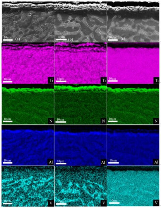
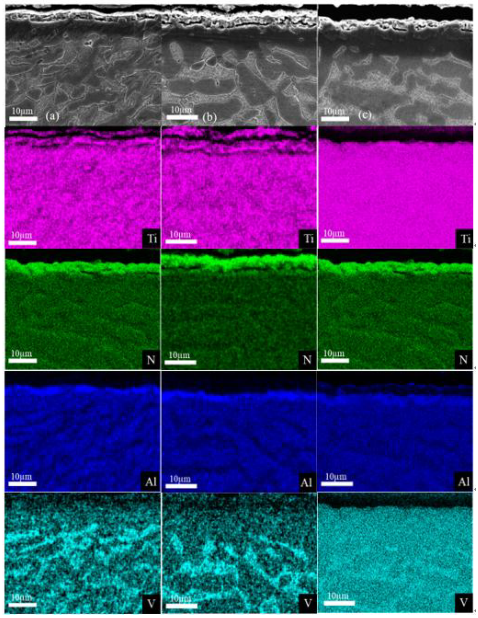
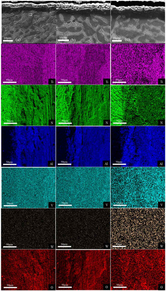
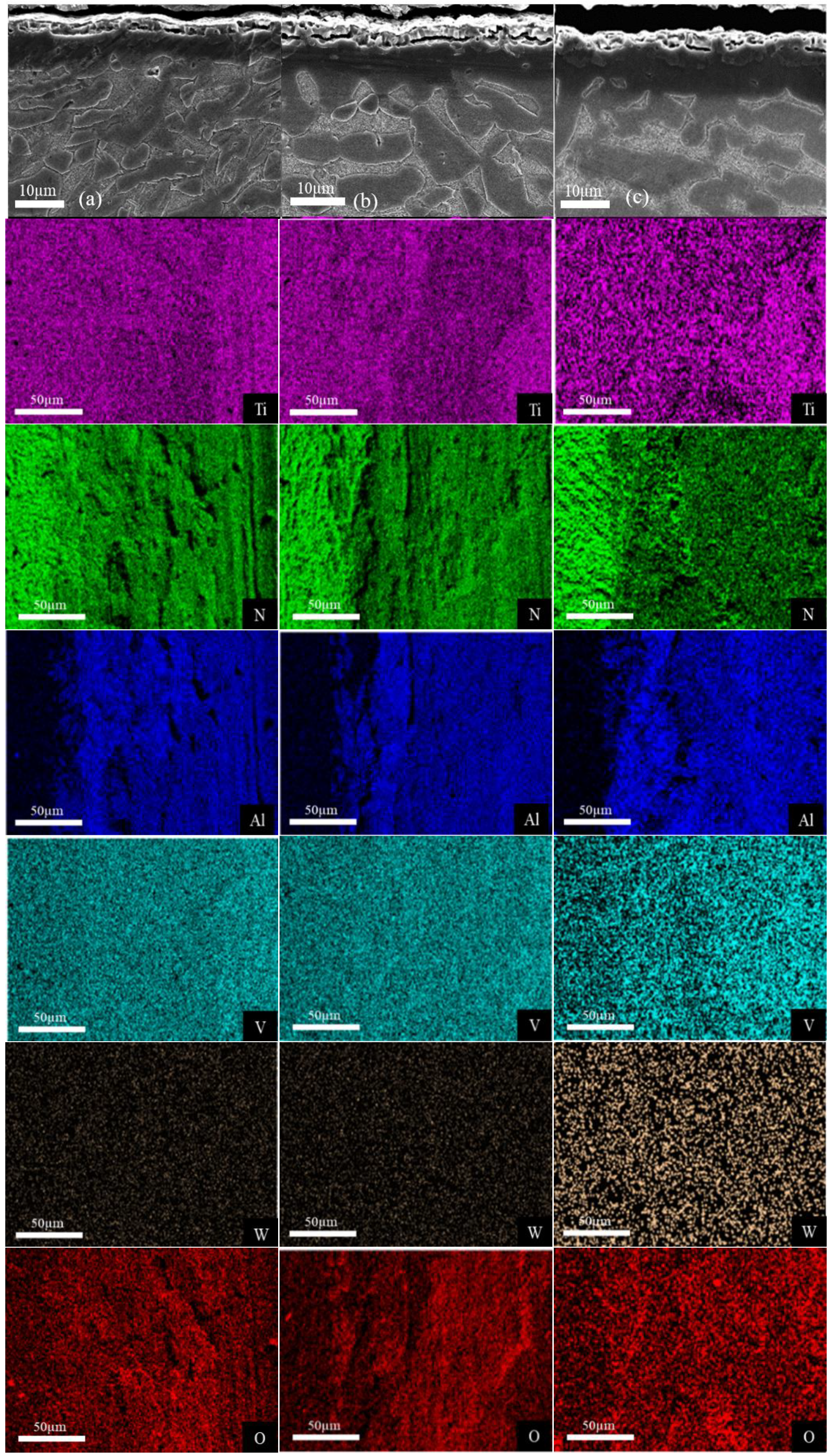
The cross-sectional EDS elemental maps are shown in Figure 5. Ti remained widely distributed throughout the analyzed region, whereas N was concentrated near the surface and gradually decreased toward the substrate. The nitrogen-enriched region became more continuous and extended farther into the substrate as the nitriding time increased from 60 to 130 min. This trend agrees with the cross-sectional SEM observations and confirms the role of holding time in controlling nitrogen penetration.
Figure 5.
Cross-sectional SEM images and EDS elemental maps of Ti-6Al-4V alloy nitrided at 950 °C for (a) 60 min, (b) 100 min, and (c) 130 min, showing the distributions of Ti, N, Al, and V.
Changes in Al and V distribution were also observed in the near-surface region. Local Al enrichment appeared below the compound layer, whereas V was more frequently detected in the subsurface region. Since Al and V are α- and β-stabilizing alloying elements, respectively, their local distributions may be related to the redistribution of the α and β phases during high-temperature nitriding. The EDS results therefore indicate that nitriding affected not only the nitrogen concentration profile but also the local elemental distribution near the modified layer [3,13,17].
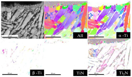
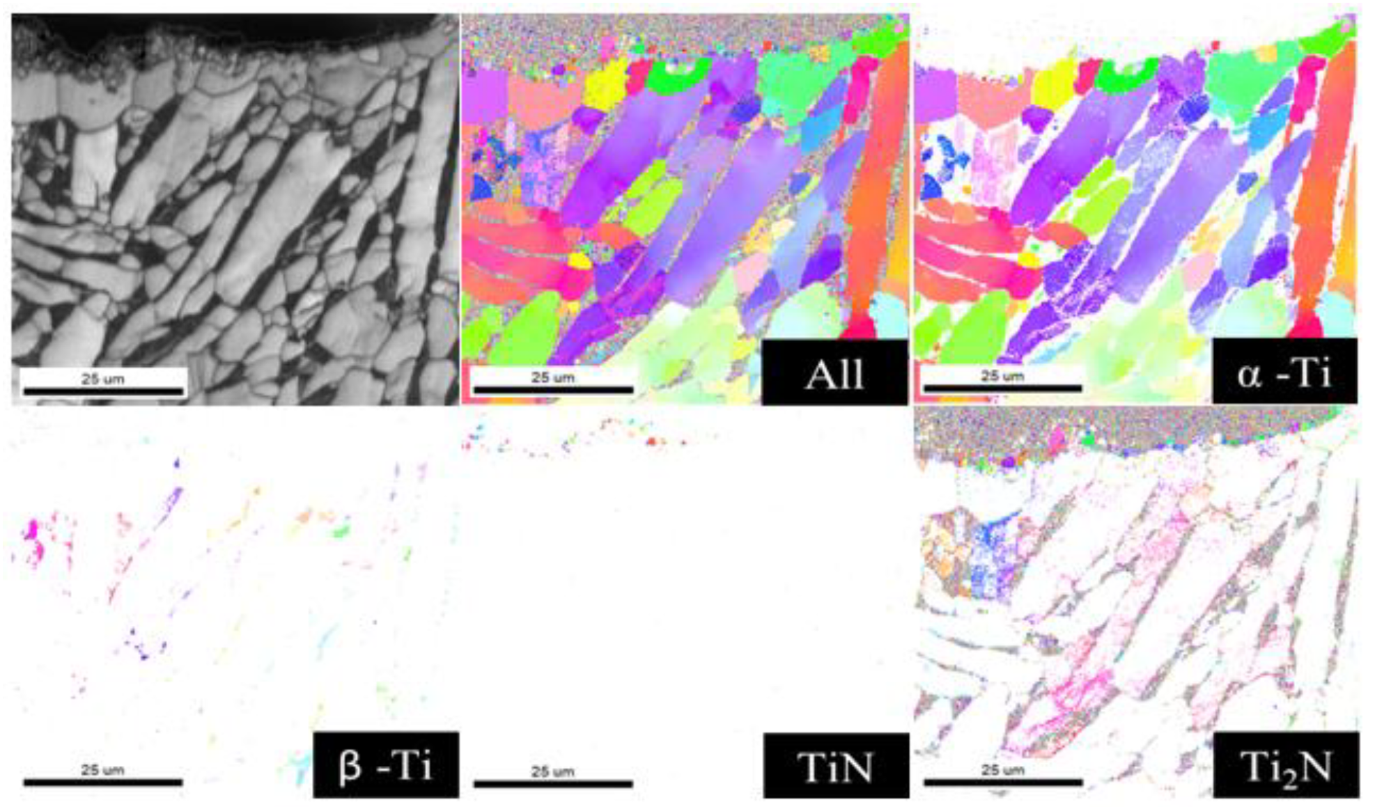
Figure 6 shows the EBSD phase map of the N60 specimen. The substrate consisted mainly of α-Ti with a lamellar morphology, while a smaller amount of β-Ti was distributed between the α lamellae and near phase boundaries. TiN was detected mainly in the outermost surface region, whereas Ti2N was observed beneath the TiN-rich region and locally along lamellar or phase-boundary regions. These observations indicate that a graded nitrided structure had already developed after 60 min at 950 °C. Because EBSD was performed only for the N60 specimen, the EBSD results are not used to compare phase evolution among the three nitriding times. For the N60 specimen, this interpretation is also consistent with the EBSD phase map in Figure 6, where TiN was mainly detected near the outer surface and Ti2N was observed beneath the TiN-rich region and along some microstructural interfaces.
Figure 6.
EBSD phase maps of Ti-6Al-4V alloy nitrided at 950 °C for 60 min, showing the distributions of α-Ti, β-Ti, TiN, and Ti2N.
The distribution of Ti2N suggests that interfaces may provide favorable paths for nitrogen transport during the early stage of nitriding. Grain and phase boundaries contain relatively high defect densities and can provide high-diffusivity paths compared with the crystal interior [45]. Local Ti2N formation along these regions is therefore consistent with preferential nitrogen diffusion through microstructural interfaces [17,45]. Together with the SEM and EDS results, the EBSD observations for the N60 specimen support the formation of a graded nitrided structure after 60 min at 950 °C.
3.2. Phase Composition and Crystal Structure
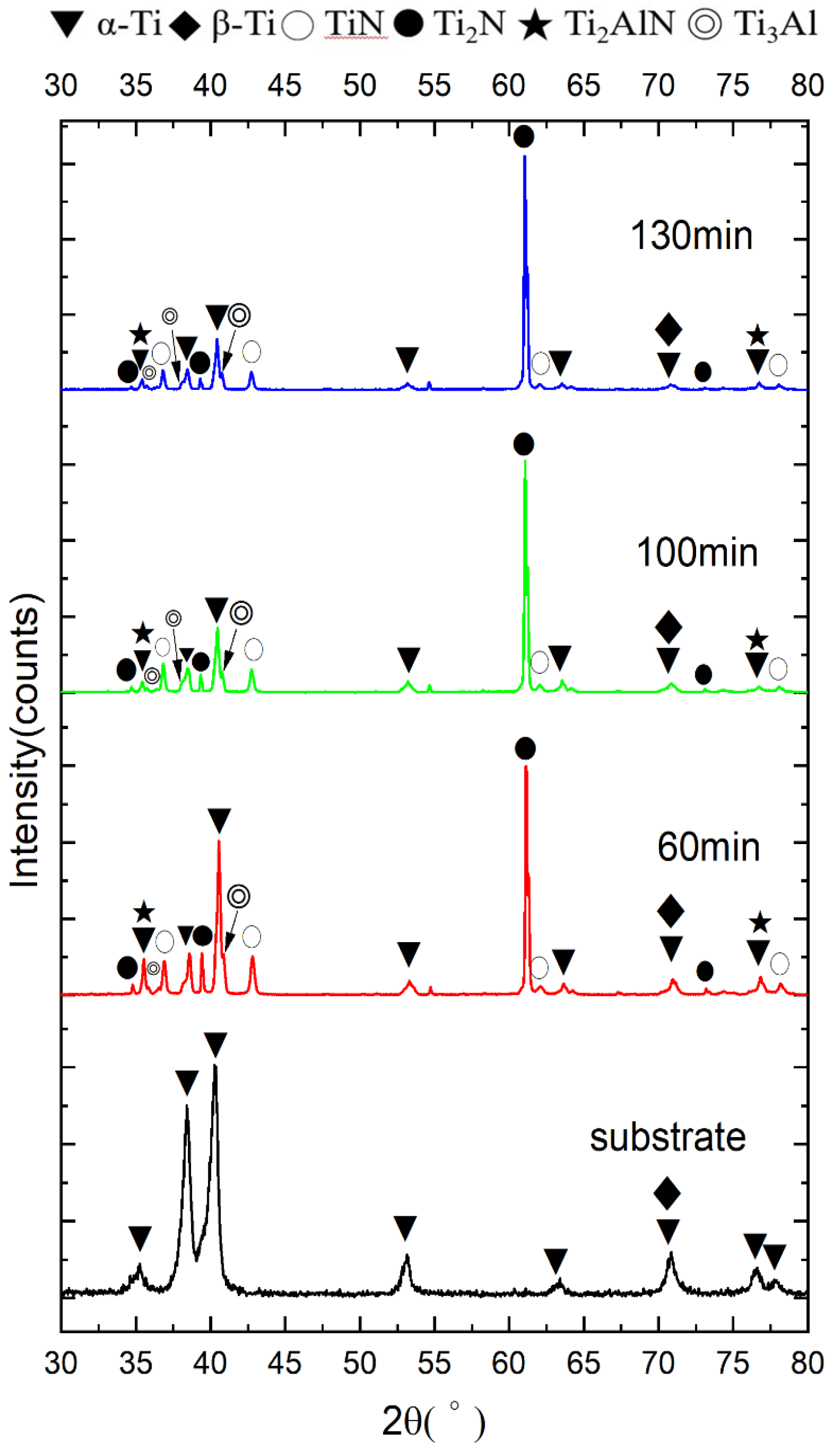
Figure 7 shows the XRD patterns of the untreated Ti-6Al-4V substrate and the specimens nitrided at 950 °C for 60, 100, and 130 min. The untreated alloy was dominated by α-Ti diffraction peaks, together with weaker β-Ti reflections, which is consistent with the typical α + β structure of Ti-6Al-4V. After nitriding, additional peaks assigned to TiN and Ti2N were detected, confirming the formation of titanium nitride phases in the modified surface region.
Figure 7.
XRD patterns of untreated Ti-6Al-4V alloy and specimens after low-pressure gas nitriding at 950 °C for 60, 100, and 130 min.
TiN and Ti2N were present after all three nitriding times. A distinct Ti2N -related reflection was observed near 2θ ≈ 61–62° and remained detectable after 60, 100, and 130 min. Ti2N is commonly formed in regions where the nitrogen concentration is lower than that required for TiN formation and can be regarded as an intermediate phase during nitriding [30]. The continued presence of Ti2N after 130 min indicates that the conversion of Ti2N to TiN was not complete under the present nitriding condition.
The coexistence of TiN and Ti2N can be related to the nitrogen concentration gradient across the nitrided layer. Nitrogen is supplied from the surface and diffuses inward during treatment. The outer region therefore has a higher nitrogen activity and favors the formation of TiN, whereas Ti2N can remain in the inner part of the compound layer where the nitrogen concentration is lower. This interpretation agrees with the cross-sectional EDS results in Figure 5, which showed a gradual decrease in nitrogen concentration from the surface toward the substrate. It is also consistent with the EBSD phase map in Figure 6, where TiN was mainly detected near the outer surface and Ti2N was observed beneath the TiN-rich region and along some microstructural interfaces.
With increasing nitriding time, the TiN-related diffraction peaks generally became more pronounced, indicating continued nitride formation and development of the nitrided layer. However, Ti2N remained present even after 130 min. This suggests that longer treatment increased the extent of nitriding but did not produce a chemically uniform TiN layer throughout the modified region. Instead, the surface retained a graded TiN/Ti2N structure.
Weak diffraction peaks assigned to Ti2AlN and Ti3Al were also observed in the nitrided specimens. Their presence suggests that Al redistribution occurred during treatment at 950 °C. Because Ti has a strong affinity for nitrogen, TiN and Ti2N preferentially form in the nitrogen-rich surface region, while Al may become locally enriched beneath the compound layer or near the compound-layer/diffusion-zone interface. Such redistribution may contribute to the formation of Al-containing phases such as Ti2AlN and Ti3Al. This interpretation is consistent with the local variation in Al distribution observed in the EDS maps. Since these diffraction peaks were relatively weak, the phase assignments should be considered together with the SEM, EDS, and EBSD results.
Overall, the XRD results indicate that nitriding at 950 °C produced a multiphase modified surface composed mainly of TiN and Ti2N, with smaller amounts of Al-containing phases. Increasing the holding time promoted nitride development, but the persistence of Ti2N after 130 min shows that a nitrogen concentration gradient remained within the nitrided layer. The resulting graded phase structure is expected to influence the hardness distribution and load-bearing response of the surface and is therefore considered in the following mechanical and tribological analyses.
3.3. Nitrided-Layer Integrity and Cross-Sectional Microhardness Distribution
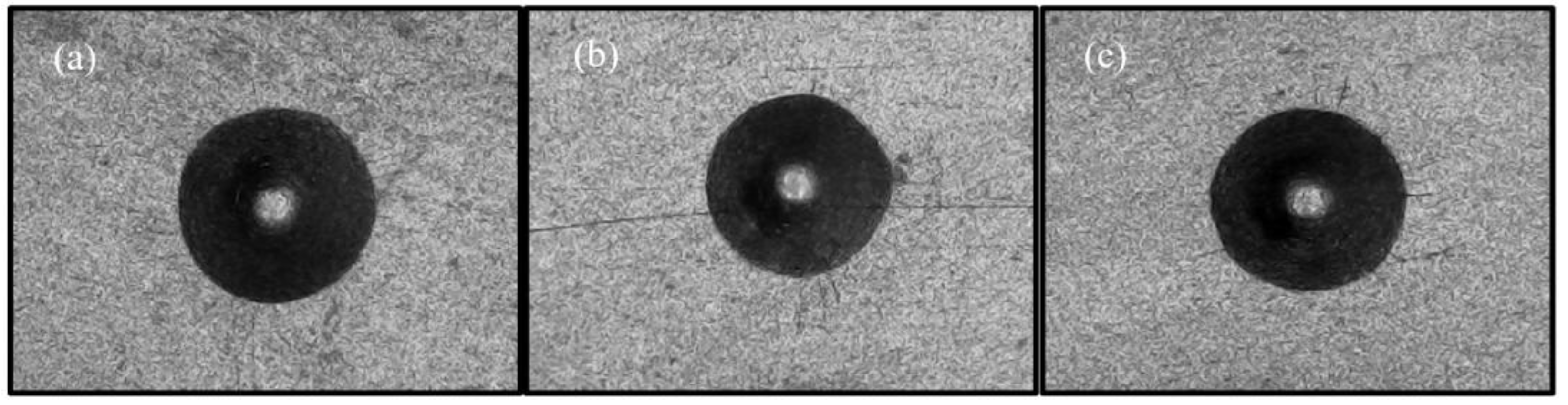
Figure 8 shows the Rockwell C indentation images of the specimens nitrided at 950 °C for 60, 100, and 130 min. Radial cracks were observed around the indentation marks for all three conditions. These cracks were mainly associated with the relatively hard and brittle TiN/Ti2N-rich surface layer under the applied load of 150 kgf. However, no extensive spallation, circumferential delamination, or obvious interfacial failure was observed around the indentation edges.
Figure 8.
Rockwell C indentation morphologies of Ti-6Al-4V alloy nitrided at 950 °C for (a) 60 min, (b) 100 min, and (c) 130 min.
According to the VDI 3198 classification, all three specimens were rated as HF1, indicating good integrity of the nitrided layer under indentation loading. As the nitriding time increased, the number and length of radial cracks increased slightly. This behavior may be related to the greater development of the nitride layer and the accompanying increase in surface brittleness. Nevertheless, no large-scale delamination was observed under the present nitriding conditions [9,20].
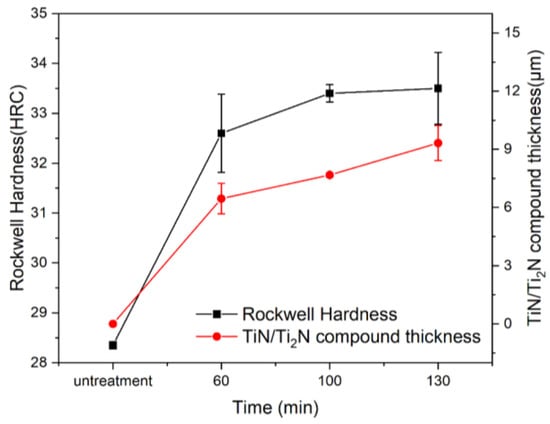
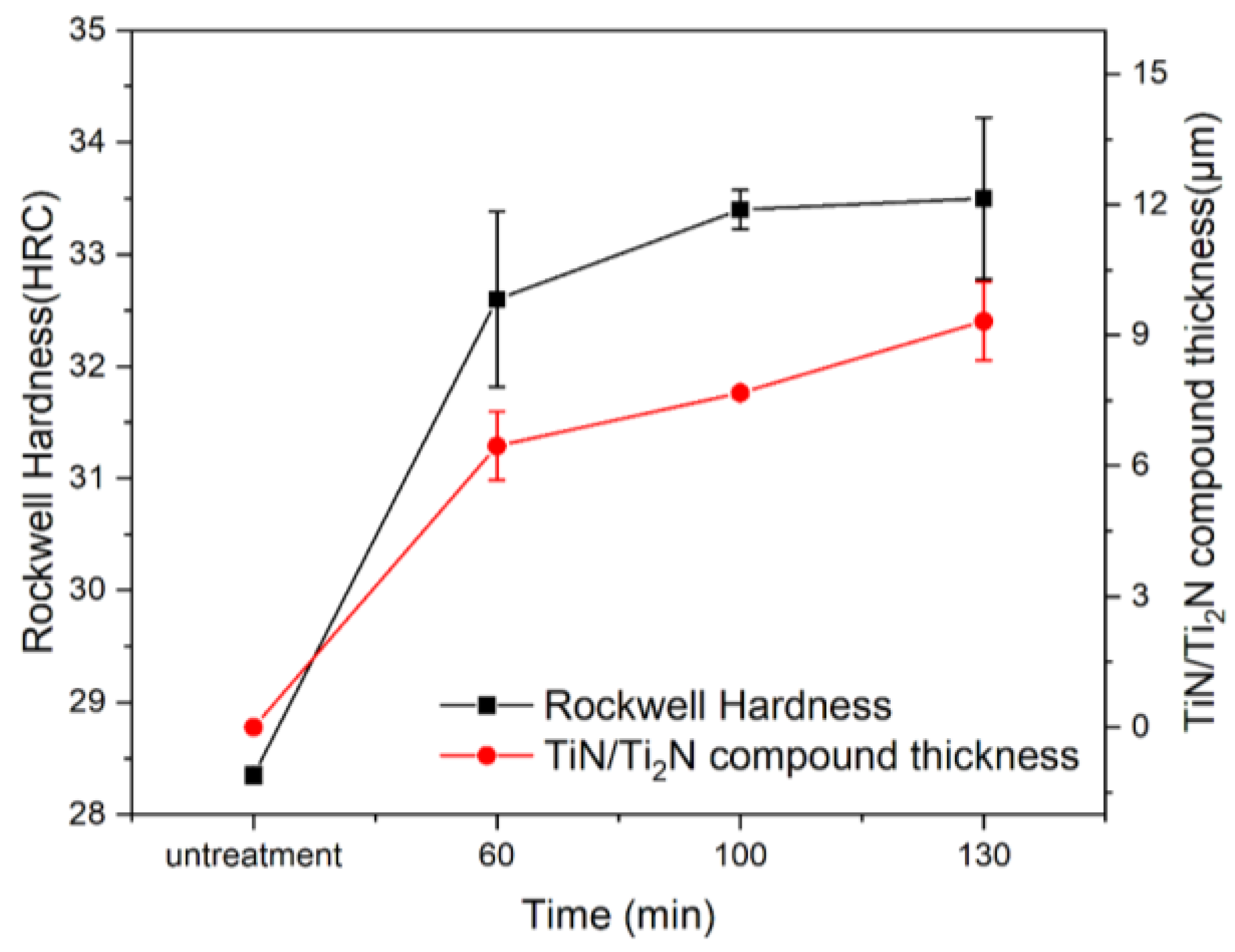
Figure 9 compares the Rockwell hardness and TiN/Ti2N compound-layer thickness as a function of nitriding time. The untreated Ti-6Al-4V alloy showed a Rockwell hardness of approximately 28.4 HRC. After nitriding for 60 min, the hardness increased markedly to approximately 32.6 HRC. A further increase in holding time produced only a small change, reaching approximately 33.4 HRC after 100 min and 33.5 HRC after 130 min. The results indicate that most of the increase in Rockwell hardness occurred during the first 60 min of treatment, after which the hardness approached a relatively stable level.
Figure 9.
Variation in Rockwell hardness and TiN/Ti2N compound-layer thickness of Ti-6Al-4V alloy with nitriding time at 950 °C.
In contrast, the TiN/Ti2N compound-layer thickness increased continuously with nitriding time. A compound layer of approximately 6 μm was obtained after 60 min, increasing to approximately 8 μm after 100 min and 9–10 μm after 130 min. The continued increase in layer thickness indicates that nitrogen diffusion and nitride growth remained active even after the Rockwell hardness had largely stabilized. This difference suggests that the development of the nitrided layer cannot be evaluated from Rockwell hardness alone.
The different trends in hardness and compound-layer thickness can be related to the nature of the Rockwell measurement. Because the indentation depth and plastic deformation zone extend beyond the thin nitrided layer, the measured Rockwell hardness reflects the combined response of the modified surface and the underlying Ti-6Al-4V substrate. Once a sufficiently hardened surface region had formed, further growth of the TiN/Ti2N layer produced only a limited increase in the overall Rockwell hardness. In contrast, SEM observations directly showed continued thickening of the compound layer with nitriding time.
This behavior is also important from a processing viewpoint. Nitriding for only 60 min at 950 °C increased the Rockwell hardness from approximately 28.4 to 32.6 HRC, accounting for most of the hardness improvement obtained during the entire treatment period. Extending the nitriding time from 60 to 130 min mainly increased the compound-layer thickness rather than the Rockwell hardness. Therefore, longer treatment should be selected according to the required layer thickness and wear resistance rather than hardness alone. From the viewpoint of processing time and thermal energy demand, the substantial hardness improvement achieved within the first 60 min also shows the potential advantage of short-duration low-pressure gas nitriding.
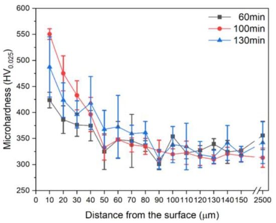
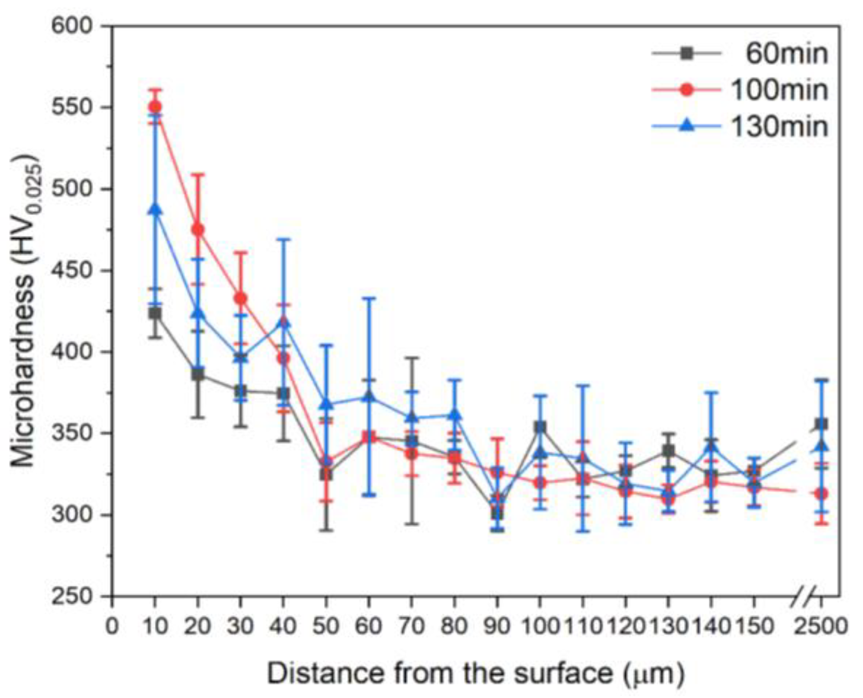
Figure 10 shows the cross-sectional microhardness profiles of the specimens nitrided at 950 °C. All specimens exhibited a clear hardness gradient, with the highest hardness near the surface followed by a gradual decrease toward the substrate. At a depth of approximately 10 μm, the N100 specimen showed the highest hardness of about 550 HV0.025, followed by the N130 specimen at approximately 490 HV0.025 and the N60 specimen at approximately 420 HV0.025.
Figure 10.
Variation in cross-sectional microhardness of Ti-6Al-4V alloy with depth after nitriding at 950 °C for 60, 100, and 130 min.
The hardness gradually approached the substrate level at a depth of approximately 40–50 μm, indicating that the main effect of nitrogen diffusion and interstitial solid-solution strengthening was concentrated in the near-surface region. The higher hardness of the N100 specimen suggests that this treatment condition produced a favorable combination of nitride formation and near-surface strengthening. In contrast, extending the treatment time to 130 min did not further increase the near-surface hardness.
The reduction in hardness after 130 min, compared with the 100 min condition, may be related to the coarsening of the nitrided surface structure and the local defects observed in Figure 3. Changes in the underlying microstructure during prolonged exposure at 950 °C may also contribute to the measured hardness response. Physical grain size and residual stress were not directly measured, their effects should be considered possible contributing factors rather than confirmed mechanisms.
The microhardness results show that surface hardening did not increase monotonically with nitriding time. The highest near-surface hardness was obtained after 100 min, whereas further treatment to 130 min resulted in a lower hardness despite the more developed nitrided region observed by SEM and EDS. This difference is important when evaluating the tribological results because the specimen with the highest hardness did not necessarily exhibit the best wear resistance, as discussed in the following section.
It should be noted that the Rockwell C hardness values represent the combined mechanical response of the nitrided surface region and the underlying substrate because the indentation-affected volume extends beyond the relatively thin TiN/Ti2N compound layer. Therefore, these values should not be interpreted as the intrinsic hardness of the outermost nitride layer. We believe that the existing Rockwell C and cross-sectional microhardness measurements remain sufficient for evaluating the comparative hardening response among the three nitriding conditions, while we acknowledge that they do not replace a direct measurement of the intrinsic hardness of the outermost nitride layer.
3.4. Wear Performance and Friction Behavior
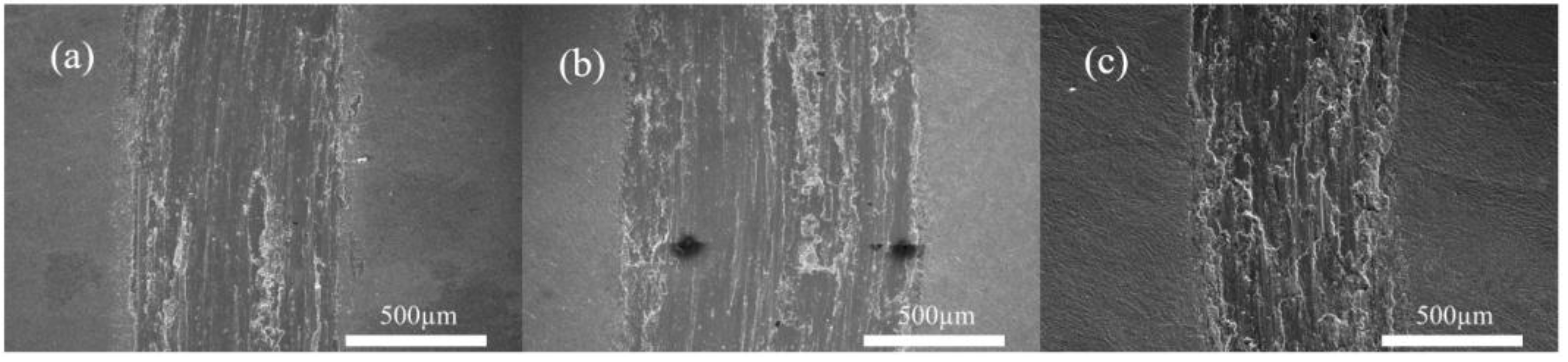
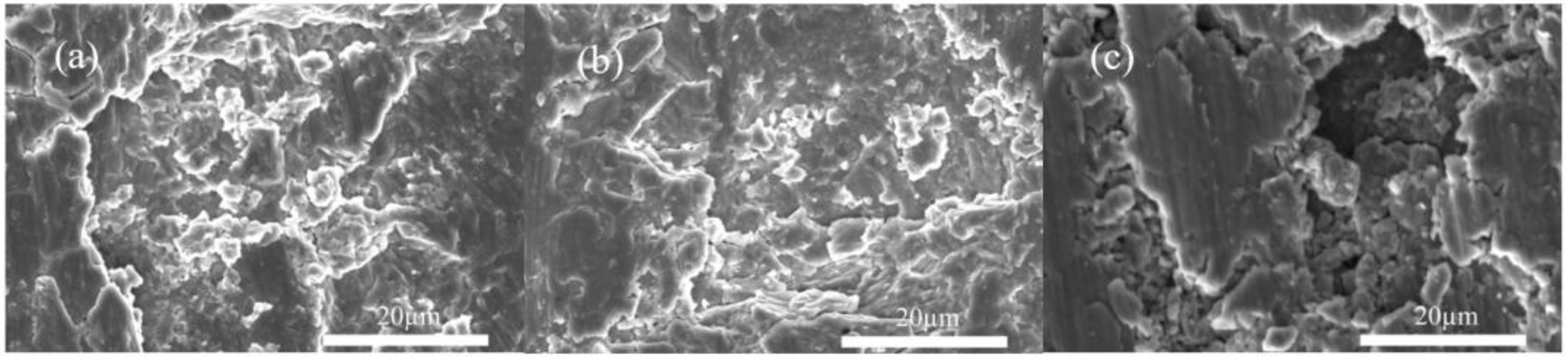
Figure 11 and Figure 12 show the SEM morphologies of the wear tracks and local delamination regions of the specimens nitrided at 950 °C for 60, 100, and 130 min under a normal load of 4 N. Grooves, scratches, and accumulated wear debris were observed along the sliding direction for all three conditions, indicating that abrasive wear was one of the main wear mechanisms. Local flake-like delamination, fragmented surface regions, and material accumulation were also observed, showing that adhesive wear and fatigue-related delamination occurred during sliding.
Figure 11.
SEM images of the wear tracks of Ti-6Al-4V alloy nitrided at 950 °C under a normal load of 4 N for: (a) 60 min, (b) 100 min, and (c) 130 min.
Figure 12.
High-magnification SEM images showing local delamination within the wear tracks of Ti-6Al-4V alloy nitrided at 950 °C under a normal load of 4 N for: (a) 60 min, (b) 100 min, and (c) 130 min.
The nitrided layer reduced plastic deformation and micro-cutting of the Ti-6Al-4V substrate because of its higher hardness. However, the relatively low ductility of the TiN/Ti2N-rich surface layer made it susceptible to cracking under repeated contact and shear loading. With increasing nitriding time, the worn surfaces showed a greater contribution from local delamination and third-body abrasion. This behavior reflects the balance between the increased load-bearing capacity provided by the nitrided layer and the brittleness associated with prolonged nitriding [14,16,22].
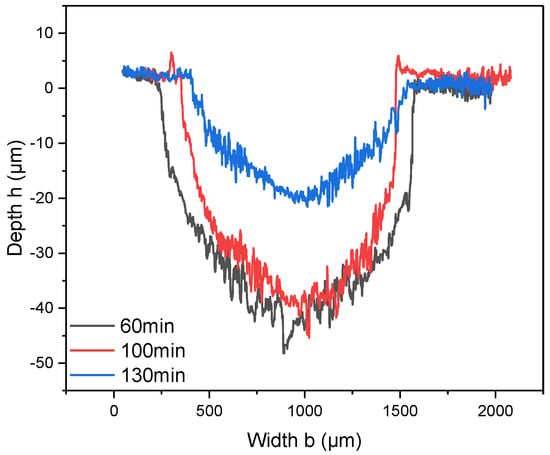
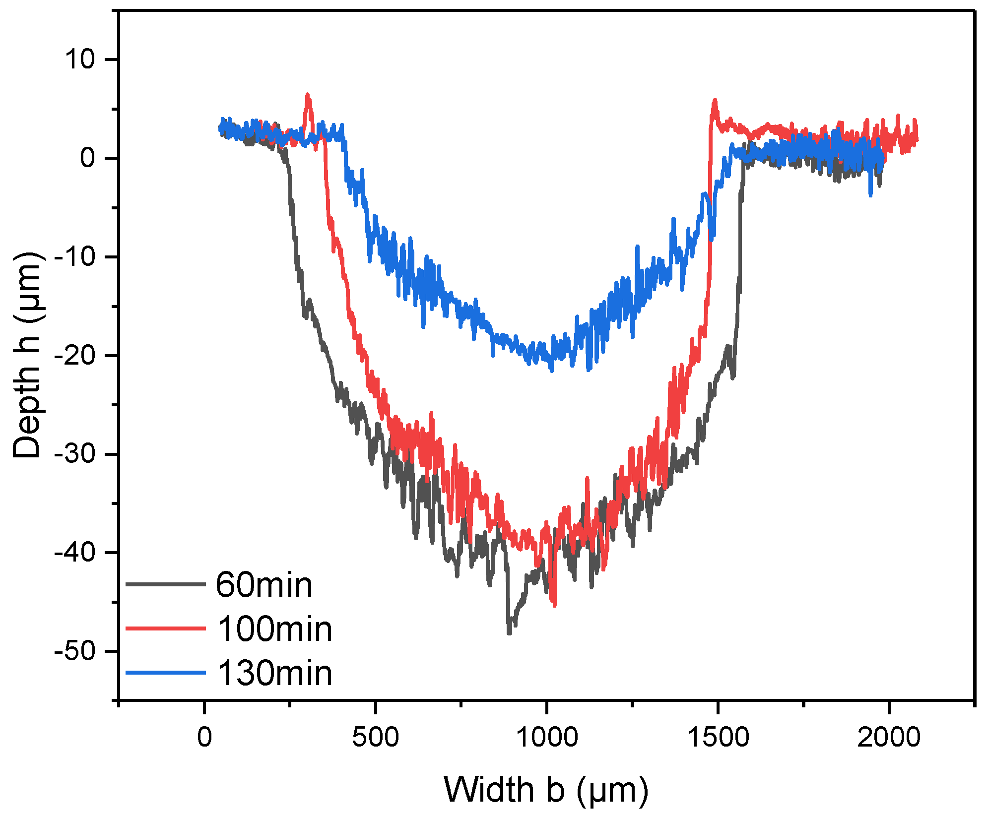
Figure 13 shows representative cross-sectional profiles of the wear tracks. After correcting the surface offset and tilt using a linear reference fitted to the unworn regions on both sides of each track, the maximum wear depths were approximately 49.2, 47.8, and 23.3 μm for N60, N100, and N130, respectively. N130 exhibited a maximum wear depth approximately 52.7% lower than that of N60 and 51.3% lower than that of N100. These values describe local penetration in the representative profiles and should be distinguished from the mean gravimetrically estimated wear volumes reported in Table 2.
Figure 13.
Cross-sectional profiles of the wear tracks of Ti-6Al-4V specimens nitrided at 950 °C for 60, 100, and 130 min after 6000 revolutions under a normal load of 4 N. The maximum wear depth was determined as the vertical distance between the unworn surface level and the deepest point of each wear track.
Table 2.
Wear cross-sectional area, wear volume, and specific wear rate of Ti-6Al-4V alloy after low-pressure gas nitriding at 950 °C under a normal load of 4 N.
For the quantitative comparison, wear volume was estimated from the measured mass loss using V = Δm/ρ, where Δm is the mass loss and ρ is the assumed Ti-6Al-4V density of 4.43 g/cm3, with appropriate unit conversion. The specific wear rate was calculated as k = V/(FL), where F = 4 N and L = 301.6 m. As shown in Table 2, the mean wear volumes of N60 and N100 were 1.053 ± 0.163 and 1.114 ± 0.226 mm3, respectively, with corresponding specific wear rates of (8.73 ± 1.35) × 10−4 and (9.23 ± 1.87) × 10−4 mm3/(N·m). N130 exhibited a lower mean wear volume of 0.722 ± 0.060 mm3 and a specific wear rate of (5.99 ± 0.50) × 10−4 mm3/(N·m). Its mean wear volume was approximately 31.4% lower than that of N60 and 35.1% lower than that of N100. The reported standard deviations describe variation among three wear tests at spatially separated locations on the same specimen, rather than reproducibility among independently prepared specimens.
Among the nitrided specimens, N130 therefore exhibited the lowest mean gravimetric wear loss, consistent with its shallower representative wear profile. Although its near-surface microhardness was lower than that of N100, N130 showed less material removal under the present sliding conditions. Its coarser initial surface morphology did not translate into greater overall wear loss, suggesting that visible surface defects alone did not determine the wear response. Local cracking and delamination may have contributed to debris formation, while the integrity and load-supporting capacity of the remaining modified region may have limited subsequent material removal. This interpretation is consistent with the importance of the mechanical integrity of the nitrided layer and its interaction with the underlying substrate in resisting scratching and local damage [46].
The compound-layer thickness increased only slightly from approximately 8 μm for N100 to 9–10 μm for N130. This difference alone does not establish the cause of the lower wear loss of N130. Similarly, the initial Sa values of approximately 0.58 μm for N100 and 0.64 μm for N130 show that the initially smoother specimen did not exhibit the lower material loss. Taken together, these results indicate that near-surface hardness, compound-layer thickness, and initial roughness do not individually provide a sufficient explanation for the observed wear ranking. Previous studies have likewise emphasized that the tribological performance of nitrided Ti-6Al-4V depends on the combined effects of surface mechanical properties, modified-layer characteristics, and sliding conditions [47,48,49]. Differences in fracture resistance, residual stress, diffusion-zone support, and debris behavior remain possible contributors, but were not quantified in the present study.
The maximum wear depths of approximately 39–62 μm exceeded the reported TiN/Ti2N compound-layer thicknesses of approximately 6–10 μm. This comparison indicates local penetration through the outer compound layer during sliding for all three nitrided conditions. Such penetration does not necessarily imply immediate exposure of the unaffected substrate, because a nitrogen-enriched diffusion zone lies beneath the compound layer. The shallower profile of N130 suggests less extensive penetration into this underlying modified region than in N60 and N100. However, identifying whether the deepest portions of the tracks remained within the diffusion zone or reached the unaffected substrate requires comparison with the local diffusion-zone depth and post-wear cross-sectional characterization.
SEM and EDS observations were consistent with local cracking, delamination, tribo-oxidation, and third-body interactions during sliding. Therefore, the lower wear loss and smaller maximum wear depth of N130 are more appropriately interpreted as the overall tribological response of the graded nitrided region rather than as a consequence of any single parameter, such as hardness, compound-layer thickness, or initial surface roughness. Although local brittle delamination was observed on N130, the lower wear volume indicates that such localized damage did not necessarily result in extensive overall material removal. Wear-track depth, cross-sectional area, and calculated wear volume therefore provide a more comprehensive description of the material-removal behavior than surface morphology alone [20,22].
Three wear tests were performed at spatially separated locations on one specimen for each nitriding condition. The resulting standard deviations describe within-specimen variation; specimen-to-specimen reproducibility was not evaluated. In addition, the present experiments do not provide direct measurements of the hardness, elastic modulus, or fracture resistance of the individual compound layers. Nanoindentation and fracture-related measurements will therefore be required in future work to determine whether differences in layer mechanical integrity contributed to the lower wear loss of N130.
Finally, because the present wear tests were evaluated only after 6000 revolutions, the exact sliding distance at which the TiN/Ti2N compound layer was penetrated cannot be determined. Accordingly, the measured maximum wear depths represent end-point values after prolonged sliding rather than direct measurements of the tribological service life of the compound layer. Interrupted wear tests at multiple sliding distances, combined with wear-depth and surface-composition measurements, will be required to identify the transition from compound-layer wear to diffusion-zone and substrate wear.
As shown in Table 2, the untreated Ti-6Al-4V specimen exhibited the lowest wear volume under the present 4 N sliding condition. Among the nitrided specimens, N130 showed the lowest wear volume and specific wear rate, whereas N60 and N100 exhibited substantially greater material loss. These results indicate that nitriding did not necessarily reduce the total wear loss under the present prolonged sliding condition. The greater material loss observed for the nitrided specimens may be associated with cracking and local delamination of the relatively brittle TiN/Ti2N-rich compound layer, which can generate hard wear debris and promote third-body abrasion. Nevertheless, the markedly lower wear loss of N130 compared with N60 and N100 suggests that its more developed compound layer and nitrogen-enriched diffusion zone provided greater subsurface support and delayed progressive material removal.
These results further demonstrate that wear behavior cannot be explained by hardness alone. Although nitriding increased the hardness of the modified surface region, higher hardness did not necessarily correspond to lower wear loss. The untreated alloy exhibited the lowest overall wear volume, whereas N130 showed the lowest material loss among the nitrided specimens. This behavior suggests that the tribological response was governed by the combined effects of near-surface hardness, compound-layer integrity, local delamination, and subsurface load-bearing capability.
It should also be noted that the present wear test was used to evaluate the overall durability of the nitrided surface system under prolonged sliding rather than the intrinsic wear resistance of each individual layer. The maximum wear depths of N60 and N100 exceeded the thicknesses of their TiN/Ti2N compound layers, indicating that the outer compound layers were penetrated during sliding and that the measured wear response included contributions from the underlying nitrogen-enriched diffusion zone and, locally, the substrate. In contrast, the substantially shallower wear track of N130 indicates that its more developed nitrided region provided better resistance to progressive material removal. Therefore, the wear-volume results for the nitrided specimens should be interpreted as the overall tribological response of the graded modified region under the present test condition rather than as the intrinsic wear resistance of the individual compound layer. Interrupted wear tests at different sliding durations and normal loads will be required in future work to clarify the layer-by-layer wear evolution and establish wear-loss–sliding-time relationships.
To further evaluate the tribological response, three wear tests were performed at spatially separated locations on the same specimen for each nitriding condition. Table 3 summarizes the corresponding average coefficient of friction and gravimetric mass-loss results.
Table 3.
Average coefficient of friction and gravimetric mass-loss results obtained from three wear tests performed at different locations on each Ti-6Al-4V specimen.
The mean COF values were 0.595 ± 0.041 for N60, 0.669 ± 0.007 for N100, and 0.742 ± 0.116 for N130. Thus, the overall friction level tended to increase with nitriding time under the present sliding condition. In contrast, the gravimetric mass-loss results did not follow the same trend. The average mass losses were approximately 4.67 ± 0.07 mg for N60, 4.93 ±0.10 mg for N100, and 3.2. ± 0.03 mg for N130.
The mean mass loss of N130 was approximately 31.4% and 35.1% lower than those of N60 and N100, respectively. This trend is consistent with the wear-track profile analysis, which also indicated lower overall material removal for N130 than for N60 and N100.
Interestingly, N130 exhibited the highest average COF but the lowest gravimetric mass loss. This result further demonstrates that the coefficient of friction alone cannot be used as a direct indicator of wear resistance. Friction reflects the dynamic interfacial shear response, whereas material removal is additionally influenced by the integrity of the nitrided region, local cracking and delamination, debris generation and removal, tribo-oxidation, third-body interactions, and subsurface load-bearing support.
It should be emphasized that the three measurements were obtained from different wear locations on the same specimen. Therefore, the reported standard deviations describe within-specimen spatial variation rather than specimen-to-specimen variability. Additional tests using independently prepared specimens would be required to establish full experimental reproducibility.
Figure 14 presents the EDS elemental maps of the wear tracks. Ti, Al, and V were detected within both the worn and unworn regions, indicating progressive removal of the nitrided surface and exposure of the underlying Ti-6Al-4V alloy. Nitrogen remained detectable in regions where the nitrided layer was not completely removed. Oxygen enrichment was observed within the wear tracks, which is consistent with tribo-oxidation occurring during repeated sliding and exposure of fresh surfaces. Although the SEM morphology and EDS elemental distributions provide evidence of grooves, local delamination, oxidation, and WC-derived material transfer, they do not allow the individual wear mechanisms to be quantified independently. Direct wear-debris analysis and cross-sectional characterization of tribofilms or transfer layers would be required to confirm the detailed sequence and relative contribution of the wear processes.
Figure 14.
SEM images and corresponding EDS elemental maps of the wear tracks of Ti-6Al-4V alloy nitrided at 950 °C under a normal load of 4 N for: (a) 60 min, (b) 100 min, and (c) 130 min.
W was detected within the worn regions and was attributed to material transfer from the WC counterbody. This observation indicates that the WC ball participated in the tribological interaction and that local counterbody material transfer occurred during sliding. The transferred W-containing debris may have acted as hard third-body particles within the sliding interface, thereby contributing to additional scratching and abrasive damage [23,24,25]. However, because the WC-ball wear scar was not directly characterized in the present study, the extent of counterbody wear could not be quantitatively evaluated. Direct SEM observation and wear-scar measurements of the WC ball will be required in future work to clarify its contribution to the overall tribological response.
Overall, the combined SEM and EDS observations are consistent with substantial abrasive wear features accompanied by local adhesion, tribo-oxidation, delamination, and third-body interactions. However, the relative contribution of each mechanism cannot be determined conclusively from the present data alone.
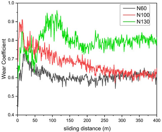
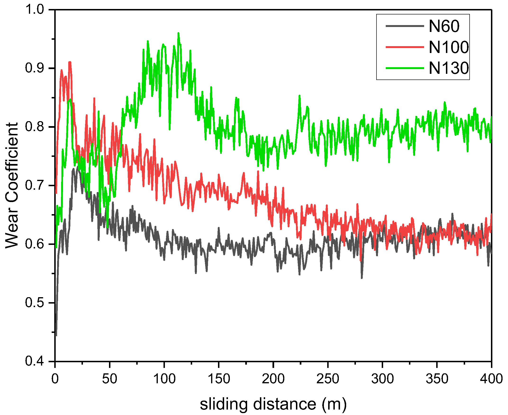
Figure 15 presents the average coefficient-of-friction (COF) curves of the N60, N100, and N130 specimens. For each nitriding condition, three wear tests were conducted at spatially separated locations on the same specimen, and each plotted curve represents the averaged friction response.
Figure 15.
Average coefficient-of-friction (COF) curves of Ti-6Al-4V specimens nitrided at 950 °C for 60, 100, and 130 min under a normal load of 4 N. Each curve represents the average response obtained from three wear tests performed at different locations on the same specimen.
The average COF values were approximately 0.595 ± 0.041 for N60, 0.669 ± 0.007 for N100, and 0.742 ± 0.116 for N130. Although N130 exhibited the highest average COF, it showed the lowest gravimetric mass loss, approximately 0.003 ± 0.0003 g, compared with approximately 0.005 ± 0.0007 g for N60 and 0.005 ± 0.0010 g for N100. This apparent mismatch between friction coefficient and material loss indicates that friction and wear were governed by different aspects of the evolving tribological interface.
The fluctuations in the COF curves may be associated with local cracking and delamination of the nitrided region, wear-debris generation and removal, tribo-oxidation, material transfer from the WC counterbody, and third-body interactions. Because the three measurements were obtained from different locations on the same specimen, the observed variation represents within-specimen spatial variability rather than specimen-to-specimen reproducibility. The intermittent entrainment, trapping, fragmentation, and removal of such debris from the contact interface can continuously alter the real contact area and interfacial shear conditions, resulting in substantial variations in the measured COF. Similar tribological studies of nitrided Ti-6Al-4V have reported that friction and wear behavior can vary considerably with the condition of the nitrided surface and the applied sliding parameters [47,48].
In addition to nitride-derived wear debris, progressive scratching, local delamination, tribo-oxidation, and material transfer from the WC counterbody may also contribute to friction instability. The SEM observations of grooves, cracks, delaminated regions, and wear debris, together with the EDS detection of oxygen and tungsten within the wear tracks, are consistent with such a dynamically evolving contact interface. However, because the wear debris was not independently collected and characterized, its phase composition cannot be directly confirmed as TiN or Ti2N. Therefore, detached hard nitride particles should be regarded as a plausible contributor to the COF fluctuations rather than as the sole confirmed origin of the oscillations.
The mean COF increased with nitriding time, whereas the mean wear loss did not follow the same trend. Therefore, COF alone could not be used to rank wear resistance. Moreover, under the present prolonged sliding condition, individual fluctuations in the COF curves cannot be uniquely assigned to penetration from the TiN/Ti2N compound layer into the nitrogen-enriched diffusion zone or substrate. The friction curves should instead be interpreted as the overall response of a continuously evolving sliding interface involving surface fracture, debris generation and removal, tribo-oxidation, material transfer, and third-body interactions.
The wear-depth results nevertheless indicate that the outer compound layers of N60 and N100 were penetrated during prolonged sliding, whereas the shallower wear track of N130 suggests delayed progression into the underlying modified region. The coefficient of friction did not vary monotonically with nitriding time and therefore cannot be used alone to rank the wear resistance of the specimens. Although N130 exhibited local delamination and friction fluctuations, it showed the lowest wear volume and specific wear rate among the nitrided specimens. This lower material loss is more reasonably associated with the greater development and load-bearing capability of the nitrided region than with the friction coefficient alone. Interrupted wear tests at different sliding durations and normal loads, combined with wear-depth and surface-composition measurements, will be required in future work to correlate changes in friction with progressive penetration through the individual modified layers.
The coefficient of friction did not vary monotonically with nitriding time. Thus, friction behavior alone cannot be used to rank the wear resistance of the specimens. In particular, the N130 specimen exhibited local delamination and friction fluctuations but still showed the lowest wear volume and specific wear rate. Its improved wear resistance was therefore more closely related to the load-bearing capability and development of the nitrided layer than to the friction coefficient alone.
When the microstructural, hardness, and wear results are considered together, the different roles of nitriding time become clear. The N100 specimen exhibited the highest near-surface microhardness, whereas N130 developed the thickest compound layer and showed the lowest wear volume. Hence, hardness, compound-layer thickness, and wear resistance did not follow the same trend with nitriding time. Under the present 4 N sliding condition, longer nitriding improved resistance to material removal mainly by increasing the development and support of the modified layer rather than by further increasing the peak hardness.
The present wear results should therefore be interpreted as a comparative assessment under a fixed severe sliding condition rather than as a complete characterization of the load- and sliding-distance-dependent wear behavior of the nitrided layers. Future work will employ multiple normal loads and interrupted sliding durations to construct wear-loss–sliding-distance relationships and identify the progressive wear of the compound layer and diffusion zone.
4. Conclusions
The effects of gas nitriding at 950 °C for 60, 100, and 130 min on the microstructure, hardness, and sliding wear behavior of Ti-6Al-4V were investigated. The following conclusions were drawn:
- Nitriding produced a graded modified region containing an outer TiN/Ti2N compound layer and an underlying nitrogen-enriched diffusion zone. The compound-layer thickness increased from approximately 6 μm for N60 to 8 μm for N100 and 9–10 μm for N130, demonstrating continued layer growth with increasing holding time.
- Hardening did not increase uniformly with nitriding duration. Rockwell hardness increased from approximately 28.4 HRC in the untreated condition to 32.6–33.5 HRC after nitriding. N100 exhibited the highest cross-sectional microhardness at approximately 10 μm beneath the surface, about 550 HV0.025, compared with approximately 420 and 490 HV0.025 for N60 and N130, respectively. Rockwell indentation produced local cracking without extensive spallation or obvious interfacial delamination.
- N130 exhibited the lowest mean gravimetrically estimated wear volume among the nitrided specimens, 0.722 ± 0.060 mm3, and a specific wear rate of (5.99 ± 0.50) × 10−4 mm3/(N·m). Its mean wear loss was approximately 31.4% lower than that of N60 and 35.1% lower than that of N100. These standard deviations represent variation among three wear locations on one specimen per condition rather than specimen-to-specimen reproducibility.
- The surface-reference-corrected maximum wear depths in representative profiles were approximately 49.2, 47.8, and 23.3 μm for N60, N100, and N130, respectively. All exceeded the corresponding compound-layer thicknesses, indicating local penetration through the outer compound layers. N130 nevertheless exhibited less extensive final penetration into the underlying modified region.
- Wear-track observations were consistent with abrasive damage accompanied by local delamination, tribo-oxidation, and WC-derived material transfer. N130 exhibited lower material loss despite having lower near-surface hardness than N100 and a slightly higher initial surface roughness. Thus, peak hardness, compound-layer thickness, and initial roughness individually did not explain the wear ranking. The results suggest that the combined response of the graded modified region, including layer integrity and subsurface support, contributed to resistance to material removal under the present 4 N sliding conditions.
Author Contributions
Conceptualization, C.-H.Y. and S.-H.C.; methodology, C.-H.Y. and S.-H.C.; investigation, C.-Q.T.; data curation, C.-Y.L.; writing—original draft preparation, C.-H.Y.; writing—review and editing, C.-H.Y. All authors have read and agreed to the published version of the manuscript.
Funding
This research received no external funding.
Data Availability Statement
The data presented in this study are available on request from the corresponding author. The data are not publicly available due to privacy or ethical restrictions.
Acknowledgments
The authors gratefully acknowledge Hsing-Kuang Industrial Co., Ltd. for providing technical guidance on the low-pressure gas nitriding process. The authors gratefully acknowledge of Hitachi SU8600 (EM0026200) belonging to the Core Facility Center of National Cheng Kung University. Special thanks are extended to Shih-Hsien Chang of the Department of Materials Science, National Taipei University of Technology, for providing access to laboratory equipment, which made the successful completion of this study possible.
Conflicts of Interest
The authors declare no conflicts of interest.
Abbreviations
The following abbreviations are used in this manuscript:
| LPON | Low-Pressure Gas Oxynitriding |
| WEDM | Wire-cut Electrical Discharge Machine |
| WC | Tungsten Carbide |
| FWHM | Full width at half maximum |
| SEM | Scanning Electron Microscope |
| EDS | X-ray spectroscopy |
| EBSD | Electron backscatter diffraction |
References
- Qu, J.; Blau, P.J.; Watkins, T.R.; Cavin, O.B.; Kulkarni, N.S. Friction and wear of titanium alloys sliding against metal, polymer, and ceramic counterfaces. Wear 2005, 258, 1348–1356. [Google Scholar] [CrossRef] [Scilit]
- He, Z.; He, H.; Lou, J.; Li, Y.; Li, D.; Chen, Y. Fabrication, structure and mechanical and ultrasonic properties of medical Ti-6Al-4V alloys. Part I: Microstructure and mechanical properties of Ti-6Al-4V alloys suitable for ultrasonic scalpel. Materials 2020, 13, 478. [Google Scholar] [CrossRef] [Scilit]
- Razzak, A.; Wang, S.; Xue, W.; Gao, S.; Wu, B.; Duan, D. Enhancing Ti6Al4V alloy fretting wear resistance: A study of duplex nitriding+ LSP surface treatments for high-temperature aero-engine components. Tribol. Int. 2026, 223, 112195. [Google Scholar] [CrossRef] [Scilit]
- Weng, Z.; Gu, K.; Cui, C.; Cai, H.; Liu, X.; Wang, J. Microstructure evolution and wear behavior of titanium alloy under cryogenic dry sliding wear condition. Mater. Charact. 2020, 165, 110385. [Google Scholar] [CrossRef] [Scilit]
- Philip, J.T.; Mathew, J.; Kuriachen, B. Tribology of Ti6Al4V: A review. Friction 2019, 7, 497–536. [Google Scholar] [CrossRef] [Scilit]
- Revankar, G.D.; Shetty, R.; Rao, S.S.; Gaitonde, V.N. Wear resistance enhancement of titanium alloy (Ti–6Al–4V) by ball burnishing process. J. Mater. Res. Technol. 2017, 6, 13–32. [Google Scholar] [CrossRef] [Scilit]
- Wang, G.; Li, J.; Cheng, Q.; Guo, Z.; Zhang, J. Hierarchical MAO–diamond coating for titanium alloys: Enhancing tribological performance through experimental and atomistic insights. Appl. Surf. Sci. 2025, 714, 164393. [Google Scholar] [CrossRef] [Scilit]
- Erdemir, A.; Donnet, C. Tribology of diamond-like carbon films: Recent progress and future prospects. J. Phys. D Appl. Phys. 2006, 39, R311–R327. [Google Scholar] [CrossRef] [Scilit]
- Zhao, S.; Feng, Y.; Luo, X.; Wang, S.; Guo, Z.; Yu, J.; Wu, Q. Study on femtosecond laser nitriding treatment on Ti6Al4V alloy and improved wear rate performance. Opt. Laser Technol. 2026, 203, 115518. [Google Scholar] [CrossRef] [Scilit]
- Lee, D.B.; Pohrelyuk, I.; Yaskiv, O.; Lee, J.C. Gas nitriding and subsequent oxidation of Ti-6Al-4V alloys. Nanoscale Res. Lett. 2012, 7, 21. [Google Scholar] [CrossRef] [Scilit]
- Zhecheva, A.; Malinov, S.; Sha, W. Titanium alloys after surface gas nitriding. Surf. Coat. Technol. 2006, 201, 2467–2474. [Google Scholar] [CrossRef] [Scilit]
- Valente, E.H.; Jellesen, M.S.; Somers, M.A.J.; Christiansen, T.L. Gaseous surface hardening of Ti-6Al-4V fabricated by selective laser melting. Surf. Coat. Technol. 2020, 383, 125278. [Google Scholar] [CrossRef] [Scilit]
- Tkachuk, O.V.; Sheykin, S.E.; Lavrys, S.M.; Rostotskii, I.Y.; Danyliak, M.-O.M.; Pohrelyuk, I.M.; Proskurnyak, R.V. Effect of stage gas nitriding on corrosion and wear resistance of Ti6Al4V alloy in physiological environment. Vacuum 2024, 230, 113713. [Google Scholar] [CrossRef] [Scilit]
- Vlček, P.; Černý, F.; Drahokoupil, J.; Sepitka, J. The microstructure and surface hardness of Ti-6Al-4V alloy implanted with nitrogen ions at an elevated temperature. J. Alloys Compd. 2015, 620, 48–54. [Google Scholar] [CrossRef] [Scilit]
- Jokanović, V.; Bundaleski, N.; Petrović, B.; Ferarra, M.; Jokanović, B.; Živković, S.; Nasov, I. Detailed physico-chemical characterization of multilayered thin films based on titanium oxynitride and copper-doped titanium nitride obtained by different PVD techniques. Vacuum 2022, 195, 110708. [Google Scholar] [CrossRef] [Scilit]
- Torrent, F.; Lavisse, L.; Berger, P.; Pillon, G.; Lopes, C.; Vaz, F.; de Lucas, M.M. Influence of the composition of titanium oxynitride layers on the fretting behavior of functionalized titanium substrates: PVD films versus surface laser treatments. Surf. Coat. Technol. 2014, 255, 146–152. [Google Scholar] [CrossRef] [Scilit]
- Subramanian, B.; Muraleedharan, C.V.; Ananthakumar, R.; Jayachandran, M. A comparative study of titanium nitride (TiN), titanium oxynitride (TiON) and titanium aluminum nitride (TiAlN) as surface coatings for bioimplants. Surf. Coat. Technol. 2011, 205, 5014–5020, Correction in Surf. Coat. Technol. 2023, 455, 129224. [Google Scholar] [CrossRef] [Scilit]
- Li, Z.; Huang, Y.; Li, P.; Dong, R.; Zhao, C.; Zhang, H. Effect of nitriding temperature on the microstructure and properties of Ti 6Al 4V coating in an atmosphere containing 0.5% oxygen. Vacuum 2026, 255, 115773. [Google Scholar] [CrossRef] [Scilit]
- Mohammadi, M.; Akbari, A.; Warchomicka, F.; Pichon, L. Depth profiling characterization of the nitride layers on gas nitrided commercially pure titanium. Mater. Charact. 2021, 181, 111453. [Google Scholar] [CrossRef] [Scilit]
- Shen, H.; Wang, L. Enhancement of wear and corrosion resistance of Ti6Al4V alloy through hollow cathode discharge-assisted plasma nitriding. Materials 2024, 17, 4386. [Google Scholar] [CrossRef] [Scilit]
- Ongtrakulkij, G.; Kajornchaiyakul, J.; Kondoh, K.; Khantachawana, A. Investigation of microstructure, residual stress, and hardness of Ti-6Al-4V after plasma nitriding process with different times and temperatures. Coatings 2022, 12, 1932. [Google Scholar] [CrossRef] [Scilit]
- Yuda, A.W.; Arifin, A.; Yani, I.; Oemar, B. Titanium nitriding: A systematic literature review. Key Eng. Mater. 2024, 978, 25–34. [Google Scholar] [CrossRef] [Scilit]
- Tokaji, K.; Ogawa, T.; Shibata, H. The effects of gas nitriding on fatigue behavior in titanium and titanium alloys. J. Mater. Eng. Perform. 1999, 8, 159–167. [Google Scholar] [CrossRef] [Scilit]
- Li, Q.; Zhu, Y.; Du, S.; Liu, X.; Li, R.; Miao, Y. Microstructure and Properties of Gas-Nitrided Ti-6Al-4V Alloy. Metals 2025, 15, 1185. [Google Scholar] [CrossRef] [Scilit]
- Hosseini, S.R.; Ahmadi, A. Evaluation of the effects of plasma nitriding temperature and time on the characterisation of Ti-6Al-4V alloy. Vacuum 2013, 87, 30–39. [Google Scholar] [CrossRef] [Scilit]
- Guo, J.; Shi, Y.; Li, C.; Zhang, G. Investigation of nitrogen ionization state and its effect on the nitride layer during fiber laser gas nitriding of Ti-6Al-4V alloy. Surf. Coat. Technol. 2021, 418, 127254. [Google Scholar] [CrossRef] [Scilit]
- Liu, G.; Wang, E.; Gao, W.; Huang, Z.; Wei, B.; Yang, Y.; Fu, Y.D. Modification mechanism of Ti-6Al-4V alloy with pre-coated Ti-Cu-Al multilayer film treated by ion nitriding: Experiments and first-principles calculations. Surf. Interfaces 2023, 40, 103004. [Google Scholar] [CrossRef] [Scilit]
- Liu, J.; Suslov, S.; Vellore, A.; Ren, Z.; Amanov, A.; Pyun, Y.S.; Ye, C. Surface nanocrystallization by ultrasonic nano-crystal surface modification and its effect on gas nitriding of Ti-6Al-4V alloy. Mater. Sci. Eng. A 2018, 736, 335–343. [Google Scholar] [CrossRef] [Scilit]
- Yilbaş, B.S.; Şahin, A.Z.; Al-Garni, A.Z.; Said, S.A.; Ahmed, Z.; Abdulaleem, B.J.; Sami, M. Plasma nitriding of Ti-6Al-4V alloy to improve some tribological properties. Surf. Coat. Technol. 1996, 80, 287–292. [Google Scholar] [CrossRef] [Scilit]
- Yang, C.H.; Li, C.Y.; Chan, C.C.; Chi, P.C.; Shih, J.H.; Liao, F.Y.; Chang, S.H. Effect of Low-Pressure Gas Oxynitriding on the Microstructural Evolution and Wear Resistance of Ti-6Al-4V Alloy. Lubricants 2025, 13, 449. [Google Scholar] [CrossRef] [Scilit]
- Xu, J.; Lane, C.D.; Ou, J.; Cockcroft, S.L.; Maijer, D.M.; Akhtar, A.; Marciano, Y. Diffusion of nitrogen in solid titanium at elevated temperature and the influence on the microstructure. J. Mater. Res. Technol. 2021, 12, 125–137. [Google Scholar] [CrossRef] [Scilit]
- Yang, C.H.; Li, C.Y.; Chang, S.H. Microstructural dependence of tribological properties of Ti-6Al-4V titanium alloy after low-pressure gas nitriding. J. Phys. Conf. Ser. 2025, 3144, 012022. [Google Scholar] [CrossRef] [Scilit]
- Januszewicz, B.; Klimek, L. Nitriding of titanium and Ti6Al4V alloy in ammonia gas under low pressure. Mater. Sci. Technol. 2010, 26, 586–590. [Google Scholar] [CrossRef] [Scilit]
- Kang, J.; Wang, M.; Yue, W.; Fu, Z.; Zhu, L.; She, D.; Wang, C. Tribological behavior of titanium alloy treated by nitriding and surface texturing composite technology. Materials 2019, 12, 301. [Google Scholar] [CrossRef] [Scilit]
- Chen, K.C.; Jaung, G.J. D.c. diode ion nitriding behavior of titanium and Ti-6Al-4V. Thin Solid Films 1997, 303, 226–231. [Google Scholar] [CrossRef] [Scilit]
- Raaif, M.; El-Hossary, F.M.; Negm, N.Z.; Khalil, S.M.; Schaaf, P. Surface treatment of Ti–6Al–4V alloy by rf plasma nitriding. J. Phys. Condens. Matter 2007, 19, 396003. [Google Scholar] [CrossRef] [Scilit]
- Zhang, Z.; Liu, G.; Chen, R.; Zhu, J. Grain boundary–dominated nitrogen diffusion during plasma nitriding of deformed TA2 alloy. Mater. Today Commun. 2026, 53, 115249. [Google Scholar] [CrossRef] [Scilit]
- Taktak, S.; Akbulut, H. Diffusion kinetics of explosively treated and plasma nitrided Ti–6Al–4V alloy. Vacuum 2004, 75, 247–259. [Google Scholar] [CrossRef] [Scilit]
- Patterson, A.L. The Scherrer Formula for X-Ray Particle Size Determination. Phys. Rev. 1939, 56, 978–982. [Google Scholar] [CrossRef] [Scilit]
- Konuru, S.L.K.; Umasankar, V.; Sarma, A. A comparison of qualitative and quantitative adhesion analysis for a composite thin film system. Mater. Today Proc. 2021, 46, 1243–1246. [Google Scholar] [CrossRef] [Scilit]
- Budinski, K.G. Tribological properties of titanium alloys. Wear 1991, 151, 203–217. [Google Scholar] [CrossRef] [Scilit]
- Straffelini, G.; Molinari, A. Dry sliding wear of Ti–6Al–4V alloy as influenced by the counterface and sliding conditions. Wear 1999, 236, 328–338. [Google Scholar] [CrossRef] [Scilit]
- ASTM G99-23; Standard Test Method for Wear and Friction Testing with a Pin-on-Disk or Ball-on-Disk Apparatus. ASTM International: West Conshohocken, PA, USA, 2023. [Google Scholar] [CrossRef] [Scilit]
- VDI 3198:1992-08; Coating (CVD, PVD) of Cold Forging Tools. Verein Deutscher Ingenieure: Düsseldorf, Germany, 1992.
- Mishin, Y.; Herzig, C.; Bernardini, J.; Gust, W. Grain boundary diffusion: Fundamentals to recent developments. Int. Mater. Rev. 1997, 42, 155–178. [Google Scholar] [CrossRef]
- Molinari, A.; Straffelini, G.; Tesi, B.; Bacci, T.; Pradelli, G. Effects of load and sliding speed on the tribological behaviour of Ti–6Al–4V plasma nitrided at different temperatures. Wear 1997, 203–204, 447–454. [Google Scholar] [CrossRef] [Scilit]
- Samanta, A.; Bhattacharya, M.; Ratha, I.; Chakraborty, H.; Datta, S.; Ghosh, J.; Bysakh, S.; Sreemany, M.; Rane, R.; Joseph, A.; et al. Nano- and micro-tribological behaviours of plasma nitrided Ti6Al4V alloys. J. Mech. Behav. Biomed. Mater. 2018, 77, 267–294. [Google Scholar] [CrossRef] [Scilit]
- Farokhzadeh, K.; Edrisy, A.; Pigott, G.; Lidster, P. Scratch resistance analysis of plasma-nitrided Ti–6Al–4V alloy. Wear 2013, 302, 845–853. [Google Scholar] [CrossRef] [Scilit]
- Rahman, M.; Reid, I.; Duggan, P.; Dowling, D.P.; Hughes, G.; Hashmi, M.S.J. Structural and tribological properties of the plasma nitrided Ti-alloy biomaterials: Influence of the treatment temperature. Surf. Coat. Technol. 2007, 201, 4865–4872. [Google Scholar] [CrossRef] [Scilit]

Disclaimer/Publisher’s Note: The statements, opinions and data contained in all publications are solely those of the individual author(s) and contributor(s) and not of MDPI and/or the editor(s). MDPI and/or the editor(s) disclaim responsibility for any injury to people or property resulting from any ideas, methods, instructions or products referred to in the content. |
© 2026 by the authors. Licensee MDPI, Basel, Switzerland. This article is an open access article distributed under the terms and conditions of the Creative Commons Attribution (CC BY) license.