


Abstract
Squeeze-Film Dampers (SFDs), with their fixed structural parameters, can easily induce detrimental nonlinear dynamic behaviors, resulting in rotor instability and fatigue damage. This paper proposes a novel partitioned oil film control method to adjust oil film stiffness and damping, thereby reducing the nonlinear vibration level of the rotor. The SFD is designed with an outer ring comprising three independently adjustable bearing pads (referred to as SSFD). The radial position of each pad is controlled by a piezoelectric actuator (PZT), enabling localized regulation of oil film clearance in different circumferential regions. This study involved developing a dynamic model of the SSFD-rotor system, which was experimentally validated. Through analysis of oil film pressure and force, we revealed the controllable mechanical properties of the SSFD. The nonlinear dynamics were thoroughly investigated. The proposed partitioned control method proved superior to the SFD, demonstrating a significant reduction in system nonlinear vibrations.
1. Introduction
The SFD has become a fundamental structure in aero-engines owing to its remarkable vibration-reduction effect, simple configuration, and ease of manufacture. It has begun to be employed in high-speed rotating equipment, including industrial compressors and turbochargers [1,2,3]. When aero-engine rotors operate, their blades inevitably accumulate damage from impacts of foreign objects such as gravel [4,5], potentially causing unbalance-induced rotor vibration. Under pronounced rotor unbalance, the stiffness coefficients of the SFD display nonlinear characteristics [2,6,7] which may trigger adverse nonlinear responses in the rotor system, leading to rotor instability and fatigue damage [8,9,10].
Many scholars have made fruitful achievements in the dynamic modeling and computational methods, the nonlinear behavior, and certain other aspects of the SFD-rotor system. Gunter [2] and Zeidan [11] observed rotor jumping phenomena in their respective experiments. Nikolajsen [12], Sykes [13] and Holmes [14] verified experimentally the existence of subharmonic response in rotor systems. These results indicate that SFD can lead to subharmonic vibrations and asynchronous vibrations in the rotor. Zhu et al. [6] reported that the rotor response exhibits multiple solution types, such as resonant, isolated bifurcation, and swallowtail bifurcation. Additionally, nonlinear dynamical behaviors, including superharmonic and subharmonic responses, were observed. Inayat-Hussain et al. [15] investigated the effects of gravitational parameters on the bifurcation behavior of SFD-supported rotors. Bonello et al. [16] analyzed rotor periodic response, employing Floquet theory to assess solution stability. Chen et al. [17] studied the nonlinear dynamic response of a rotor with SFD. Chen et al. [18] incorporated oil film inertia effects into their model to study rotor vibration, revealing that base harmonic excitation triggers the transition from periodic to quasi-periodic motion. Luo et al. [19] explored the dynamic coupling between the rotor and its supporting structures. All the above-mentioned vibration phenomena originate from the nonlinearity of SFD within the rotor system.
To enhance damping performance and reduce nonlinearity, scholars have conducted extensive research on various improved designs of SFDs. Zhao JY et al. [10] devised an improved SFD incorporating a floating ring between the journal and pedestal. Their results demonstrated that this design effectively suppresses bistable and non-synchronous motions in rigid rotors. M.A. Rezvani et al. [20] investigated the performance of this damper on flexible rotors, and found that both ring stiffness and rotor imbalance significantly influence vibration response. Zhou et al. [21] explored the dynamic behaviors of rotor assemblies mounted on diverse floating-ring SFDs, and contrasted their performance with that of SFD configurations. The results demonstrate that floating ring SFDs are more effective than SFD in suppressing bistable motion, non-synchronous vibration, and transient amplitude. Hong et al. [22] demonstrated that the elastic-ring SFD (ERSFD) features a segmented oil film clearance which can be regulated through elastic deformation of the ring. This adjustability helps maintain the clearance within an optimal range, thereby effectively mitigating nonlinear vibration in the rotor system. Han et al. [23] demonstrated that the ERSFD can effectively suppress the nonlinear bistable response of the rotor. Zeidan, Santiago, and San Andres put forward the Integrated Squeeze-Film Damper (ISFD), which features a more compact layout relative to SFDs. Santiago et al. [24] demonstrate that ISFD has excellent vibration reduction effects. Ertas et al. [25] employed the ISFD to suppress the sub-synchronous vibration of a rotor. Although improved SFDs effectively reduce the nonlinearity of rotor vibrations, their oil film forces cannot be actively regulated according to operational conditions.
To enhance the environmental adaptability of SFD, various types of active SFDs have been developed. Zheng et al. [26] reduced the resonance amplitude of the rotor when passing through the critical speed by adjusting the oil film clearance of the SFD. EI-Shafei et al. [27,28] developed a hybrid damper capable of operating in both short and long damping modes under controller, and evaluated the performance of different control algorithms in actively suppressing rotor vibrations. Morishita et al. [29] employed electro-rheological fluid within the SFD for flexible rotor vibration attenuation. Seungchul et al. [30] investigated the design scheme and practical implementation of electrorheological fluid dampers for rotor system vibration suppression. Wang et al. [31,32] achieved independent regulation of oil film pressure within each bearing region by electrical current, and found that this considerably mitigates the nonlinearity of rotor vibration, in comparison with conventional magnetorheological dampers. PZT is widely used in structural vibration reduction due to its characteristics of fast response speed, ability to achieve micron-level displacement, and high thrust. Lu et al. [33] proposed a novel structure employing PZT actuators to tune an SFD for attenuating unbalanced vibration responses of the rotor, yet its theoretical model was relatively simplified. Palazzolo et al. [34] deployed PZT actuators to achieve vibration suppression of rotor systems. Their results demonstrate that an active control strategy employing velocity feedback can significantly suppress unbalanced response, transient vibrations, and sub-synchronous vibrations. Tůma et al. [35] experimentally demonstrated that active control of the bushing movement using a PZT actuator can effectively broaden the operational speed range of journal bearings. Jungblut et al. [36] designed an active piezoelectric bearing incorporating rotating actuators, evaluating its viability as an active balancing device and comparing its performance with existing technologies. In a subsequent study by the same group [37], PZT was employed to actuate the rotating shaft based on rotor relative displacement feedback, effectively attenuating rotor vibration without a significant increase in bearing forces. Simoes et al. [38] successfully attenuated both steady-state and transient rotor vibrations using a PZT actuator implemented with a modal control strategy. Zhang et al. [39,40] employed PZT to regulate oil film clearance and thereby attenuate the unbalance response of the rotor. However, they did not consider the suppression of nonlinear vibration of the SFD-rotor system under large eccentricity conditions. The novelty and contribution of this work lie in its comparing the nonlinear vibrations of the SSFD-rotor system and the SFD-rotor system, demonstrating that SSFD exhibits superior performance in suppressing rotor nonlinear vibration. The above literature review reveals that relatively few studies have focused on the active manipulation of SFDs via PZT for mitigating nonlinear vibration in rotor systems.
SFDs tend to introduce undesirable nonlinear vibrations within rotor systems. To alleviate such rotor nonlinearity, a novel oil film control strategy is proposed in this work. The layout of this paper is arranged as follows: Section 2 formulates the governing equations for the SSFD-rotor system; Section 3 investigates the controllable characteristics of the SSFD; Section 4 explores the nonlinear vibration responses of the rotor system; and Section 5 concludes this work.
2. SSFD-Rotor System Dynamic Model
2.1. Working Principle of SSFD
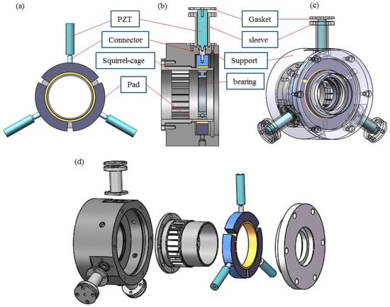
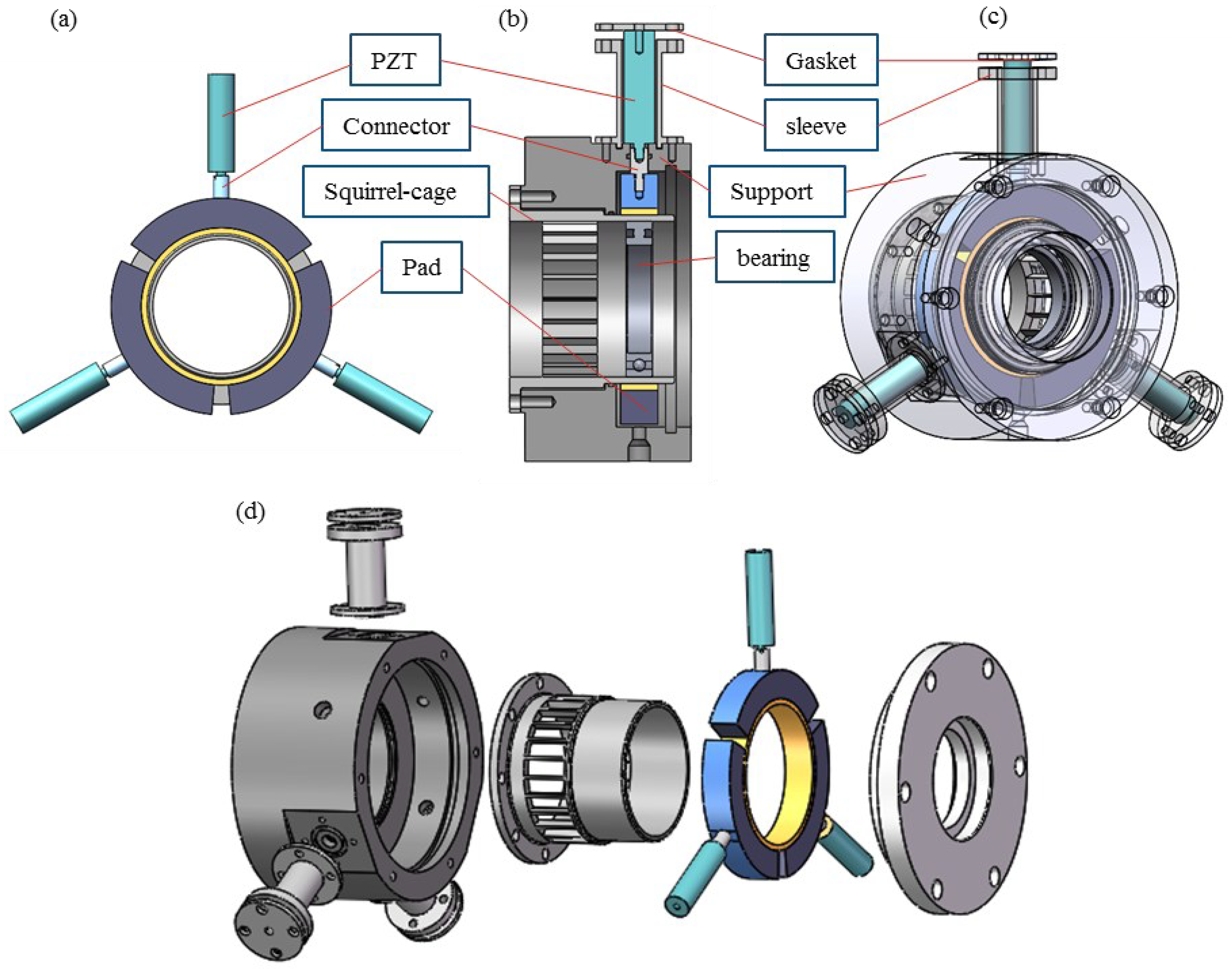
Figure 1 presents the configuration of the SSFD from multiple perspectives. Its outer ring comprises three identical bearing pads that collectively form a continuous circular support surface. Each pad is coupled to a PZT actuator. Upon electrical excitation, the PZT generates axial deformation, which drives radial displacement of the pad. This displacement modulates the local oil film. Because each pad can be actuated independently, this arrangement allows localized tuning of oil film characteristics at different circumferential positions.
Figure 1.
Schematic illustration of the SSFD. (a) Key components. (b) Cross-sectional view. (c) General assembly. (d) Explosive view.
2.2. Dynamic Modeling of Support System with SSFD
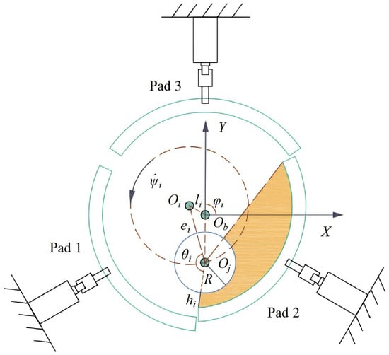
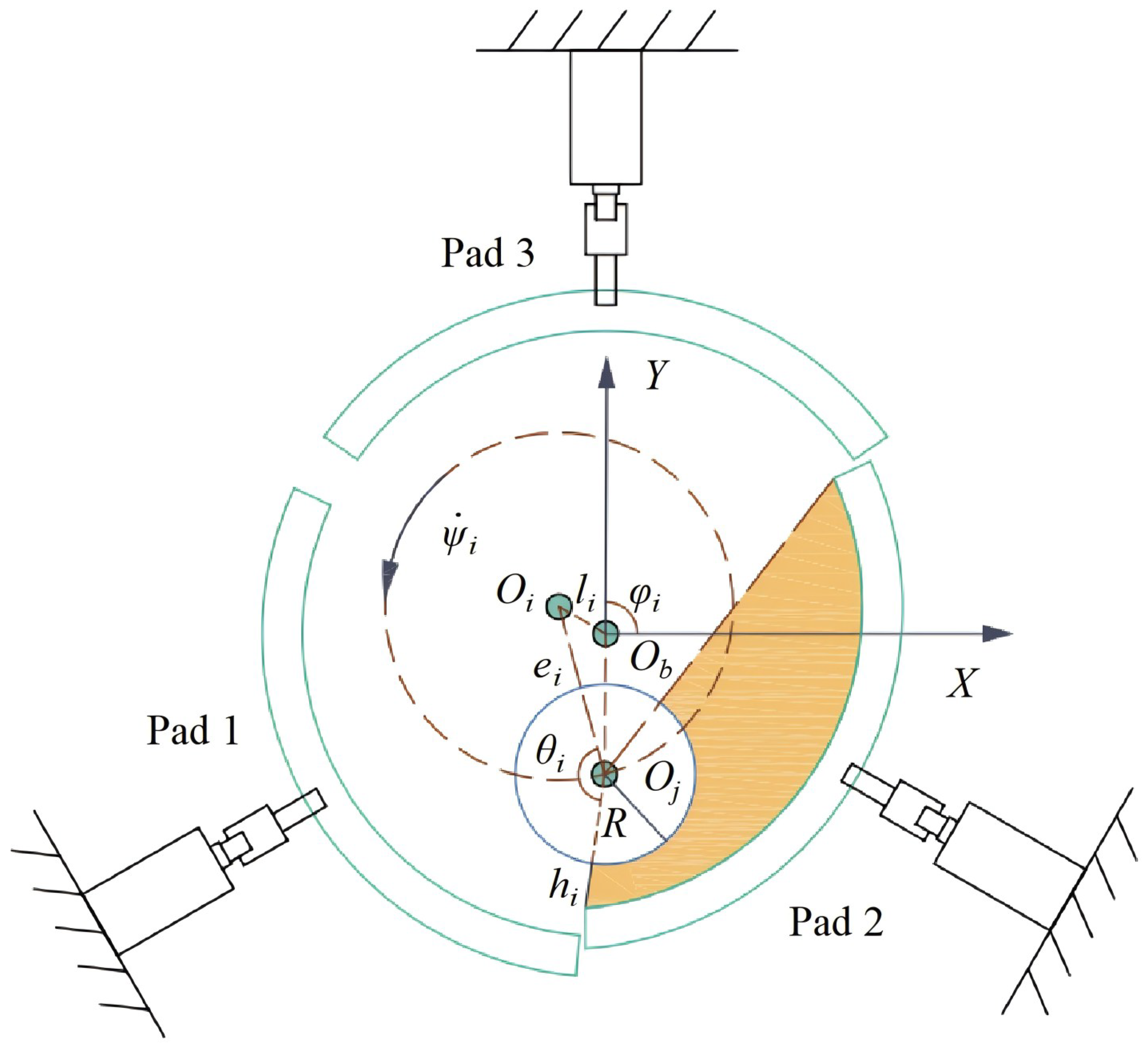
Figure 2 shows a schematic cross-section of the SSFD. Here, R stands for the journal radius, and Rb refers to the radius of the bearing pad. The dimension L describes the axial length of the oil film. Ob and Oj correspond to the centers of the bearing housing and journal, respectively. Oi marks the center of the i-th bearing pad (i = 1,2,3). is defined as the angle formed between the central axis of the i-th bearing pad and the X-axis, which identifies the circumferential location of this pad. ei expresses the eccentricity separating the journal center from the center of the i-th bearing pad, with εi being its associated eccentricity ratio. hi signifies the oil film thickness between the journal and the i-th bearing pad, and defines the azimuth angle for oil film pressure. represents the relative precessional angular speed of the journal, and indicates the radial displacement of the i-th bearing pad.
Figure 2.
Schematic diagram of working principle of SSFD.
When the PZT elongates, the oil film between the bearing pads and journal is squeezed, while the oil film between the bearing pads and bearing housing remains uncompressed. Therefore, the oil film force between the bearing pads and bearing housing is not considered in the derivation of the SSFD dynamic equation. For the i-th bearing pad, the Reynolds equation is expressed as:
where denotes the oil film pressure of the i-th bearing pad, and represents the oil film viscosity. The oil film thickness hi can be expressed as:
where c is the initial oil film clearance.
Suppose the displacement of the journal center Oj is . The relative displacement of the journal center with respect to Oi is taken as (x, y).
Based on the Reynolds boundary condition and geometric trigonometric relations, the oil film pressure region for the i-th bearing pad is defined within the interval . Consequently, the corresponding oil film forces for the i-th bearing pad can be calculated using the following expressions:
Through coordinate transformation, the horizontal and vertical components of the oil film force are resolved as follows:
Hence, the horizontal and vertical oil film forces of SSFD are:
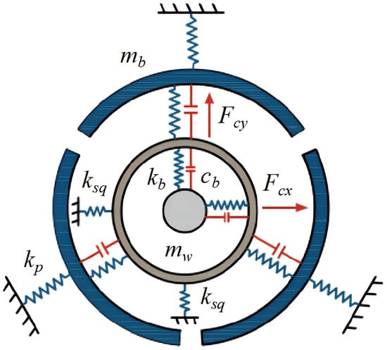
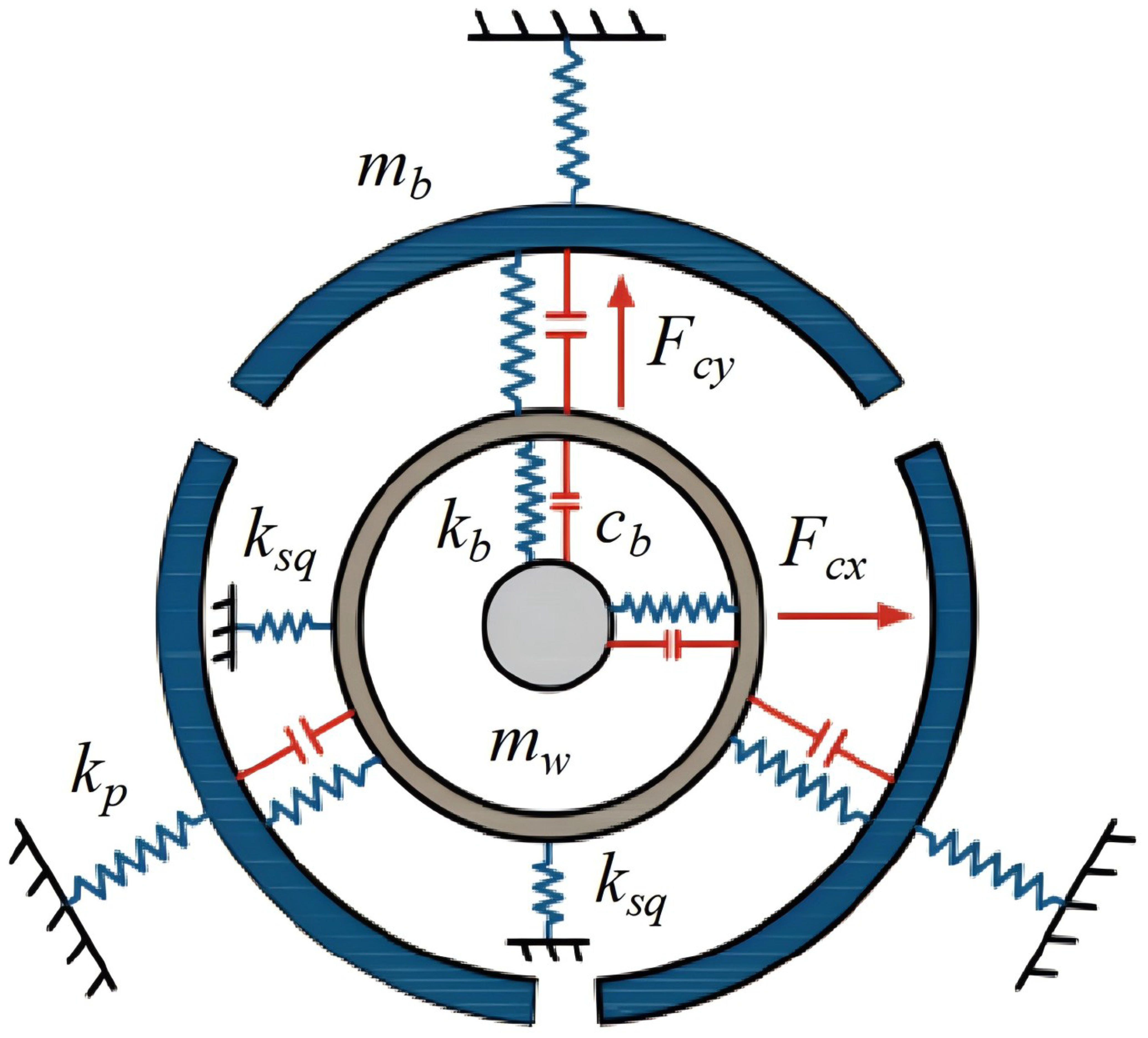
The equivalent dynamic model of the rotor support system with SSFD is shown in Figure 3, where mb denotes the bearing pad mass and mw denotes the bearing outer ring mass. The equivalent stiffness and damping of the bearing are kb and cb, the stiffness of the squirrel-cage elastic support is ksq, and the equivalent stiffness of PZT is kp. The governing equation of the support system with SSFD can be expressed as:
Figure 3.
Schematic of equivalent dynamic model of rotor support system with SSFD.
In the formula, xw1 and yw1 denote the horizontal and vertical displacements of the bearing outer ring; Fbx1 and Fby1 represent the horizontal and vertical bearing forces; Fc1, Fc2 and Fc3 are the oil film forces acting on each bearing pad; Fa1, Fa2 and Fa3 are the PZT actuation forces applied on each bearing pad. With the creep and hysteresis characteristics of PZT neglected, the electromechanical equation is written as:
In the formula, d33 is the piezoelectric coefficient of PZT, and Ui(t) denotes the driving voltage of the PZT connected to each pad.
As derived from the above formulas, the PZT, bearing pad, oil film, and rotor are mutually coupled. Controlled by the applied voltage, the PZT drives the bearing pad to produce a displacement li. The movement of the bearing pad affects the squeezing region of the oil film, thereby altering the oil film force. The oil film force acts on the journal, and the vibration of the journal varies with the change in the oil film force.
The dynamic equation of the rotor support with SFD can be expressed as:
where xw2 and yw2 denote the horizontal and vertical displacements of the bearing outer ring, Fbx2 and Fby2 are the bearing forces in the horizontal and vertical directions, and Fsx and Fsy represent the oil film forces of the SFD in the horizontal and vertical directions.
2.3. Dynamic Formulation for the SSFD-Rotor System
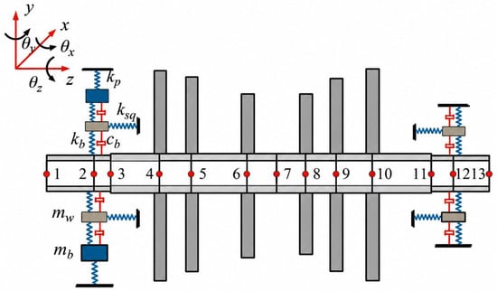
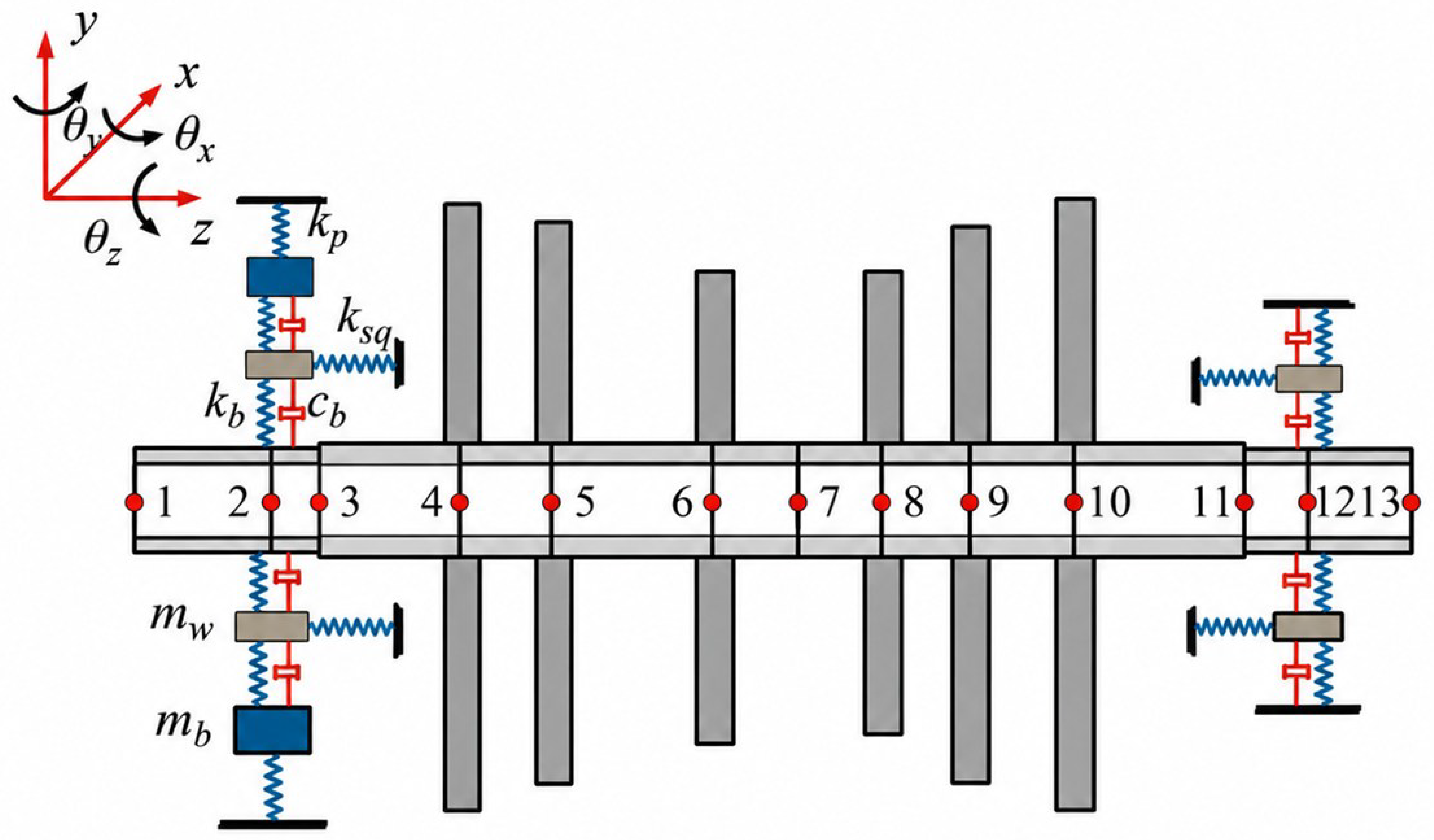
The equivalent dynamic representation for the SSFD-rotor system is shown in Figure 4. This rotating shaft is discretized by twelve Timoshenko beam elements, comprising 13 nodes in total. Disks are modeled as lumped masses. The left-side support is configured as an SSFD equipped with PZT, while the right-side support consists of a SFD.
Figure 4.
Dynamic schematic of the SSFD-rotor system.
Because the rotor gravity is balanced with the initial supporting force of the squirrel-cage elastic support, the rotor gravity is neglected in the model. Based on the finite element method, the dynamic equation of the rotor system is derived. By combining this with the governing equation of the support system, the governing equation for the SSFD-rotor assembly can be derived as follows [39,40]:
In this expression, , , , and represent the mass, damping, gyroscopic and stiffness matrices for the SSFD-rotor assembly; denotes the external excitation vector, while stands for the generalized coordinate vector.
The dimensional parameters of the shaft and disk are shown in Table 1 and Table 2. The shaft and disk are both made of steel with a density of 7850 kg/m3. The elastic modulus and Poisson’s ratio of the shaft a2re 2.1 × 10¹¹ Pa and 0.3, respectively. In this simulation, the disk is regarded as a rigid body, so the elastic modulus and Poisson’s ratio of the disk are not considered. The equivalent dynamic coefficients of the bearing and squirrel-cage elastic support are identical in the horizontal and vertical directions. The equivalent stiffness of the bearing is 2.2 × 10⁸ N/m, and the equivalent bearing damping coefficient is 40 N·s/m. The equivalent stiffness of the squirrel-cage elastic support is 1.35 × 10⁷ N/m. The physical parameters of the SSFD are set as follows. The initial oil film clearance is 120 × 10−6 m, the oil film width is 12 × 10−3 m, and the oil film dynamic viscosity is 1.075 × 10⁻² Pa·s. The PZT actuator has a maximum stroke of 76 μm, a driving voltage range of 0–150 V, a stiffness of 100 N/μm, a length of 91 mm, and a response time of 10 ms.
Table 1.
The structural dimensions of the shaft.
Table 2.
The structural dimensions of the disk.
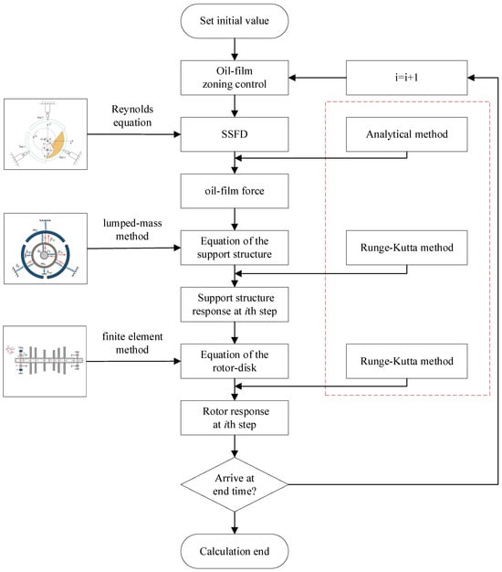
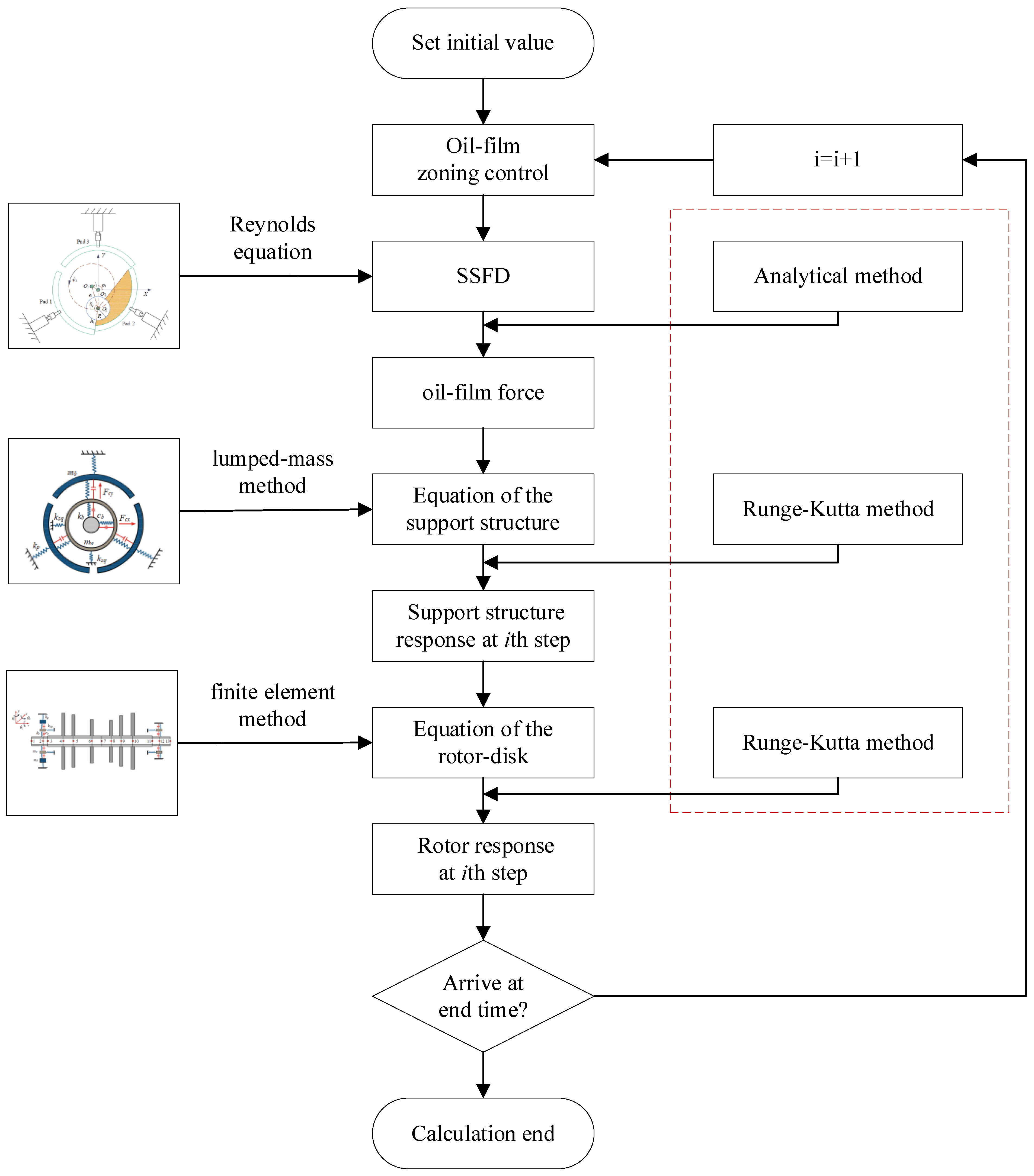
The computational process of the SSFD-rotor system are shown in Figure 5.
Figure 5.
SSFD-rotor system calculation flow chart.
- (1)
- The initial oil film force, the displacement and velocity of the shaft journal at the rotor support, and the PZT driving voltage are all set to zero.
- (2)
- The oil film pressure and oil film force of the SSFD are obtained by the finite difference method and the analytical method, respectively.
- (3)
- The governing equation of the rotor support is solved by using the Runge–Kutta method to obtain the dynamic response and interaction forces of the rotor support system. The rolling bearing forces at the rotor support nodes are added to the external excitation force vector of the dynamic equation of rotor.
- (4)
- By using the Runge–Kutta method to solve the dynamic equation of rotor, the dynamic responses of various nodes are obtained.
- (5)
- The above process is repeated to obtain the responses and forces of the SSFD-rotor system within a given time range.
2.4. Validation of the SSFD-Rotor System Governing Equation
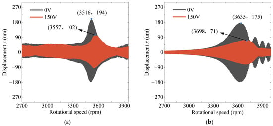
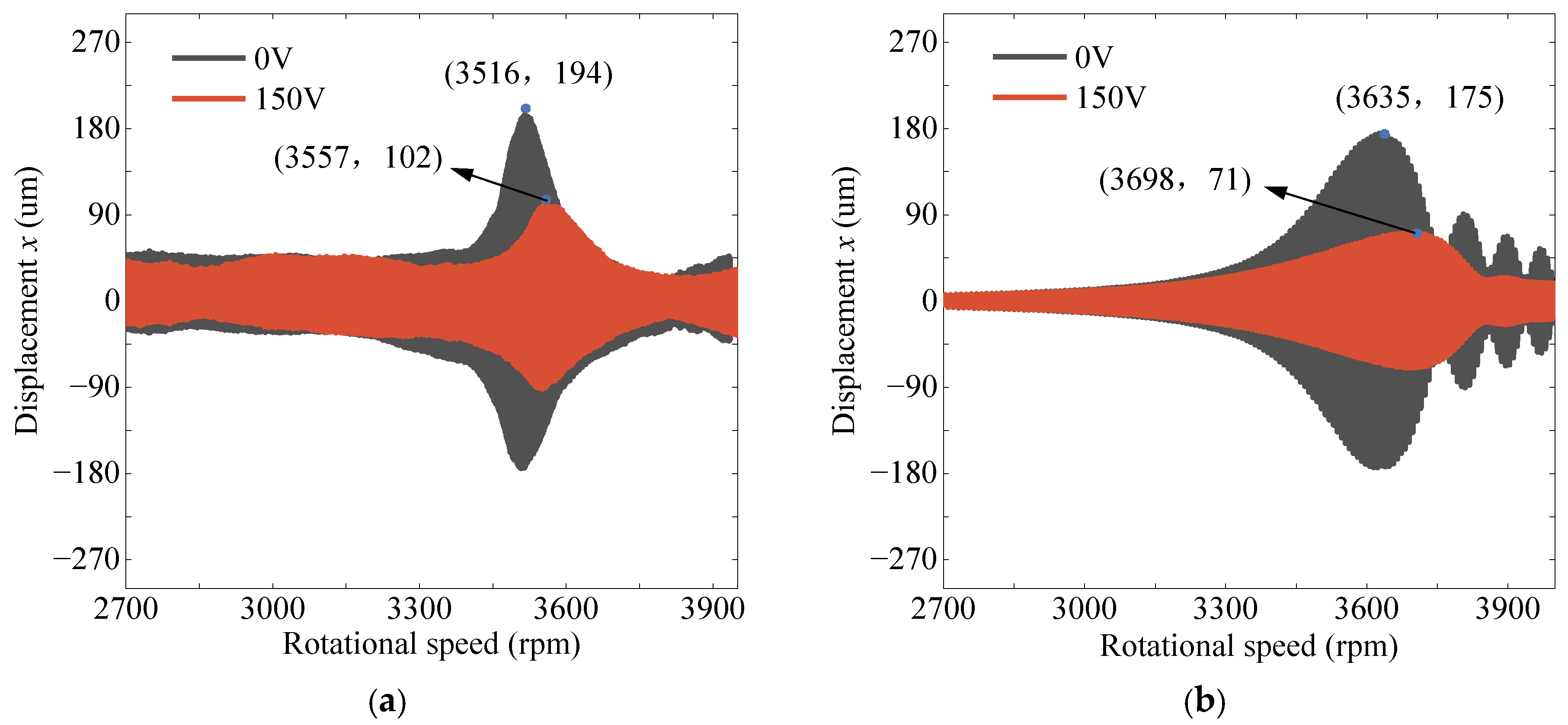
An experimental test rig [40] was established. The rotating speed was ramped up gradually to 4000 rpm, while the PZT driving voltage was set separately to 0 V and 150 V to acquire the rotor vibration across a range of rotational speeds. To validate the accuracy and reliability of the governing equation for the SSFD-rotor assembly, measured data were contrasted against numerical predictions. Comparisons of the transient response at Node 7 during rotor run-up for distinct actuation voltages are presented in Figure 6. Both the measured and numerical data reveal a clear reduction in resonant amplitude near the critical speed when the actuation voltage increases from 0 V to 150 V, thereby confirming the validity of the governing equation.
Figure 6.
Measured and numerically predicted transient response at Node 7 during rotor run-up for various PZT actuation voltages. (a) Experimental result. (b) Simulation result.
3. Dynamic Performance of the SSFD
Once the bearing pad is displaced, the squeezed region of the oil film between the pad and journal is altered, and the oil film pressure on the pad changes correspondingly. The precession angle defines the azimuth of journal whirl within the oil film and is set to π/6, with a rotational speed of 3000 rpm.
3.1. Oil Film Pressure
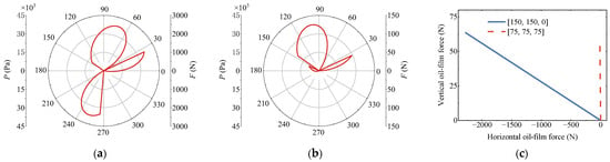
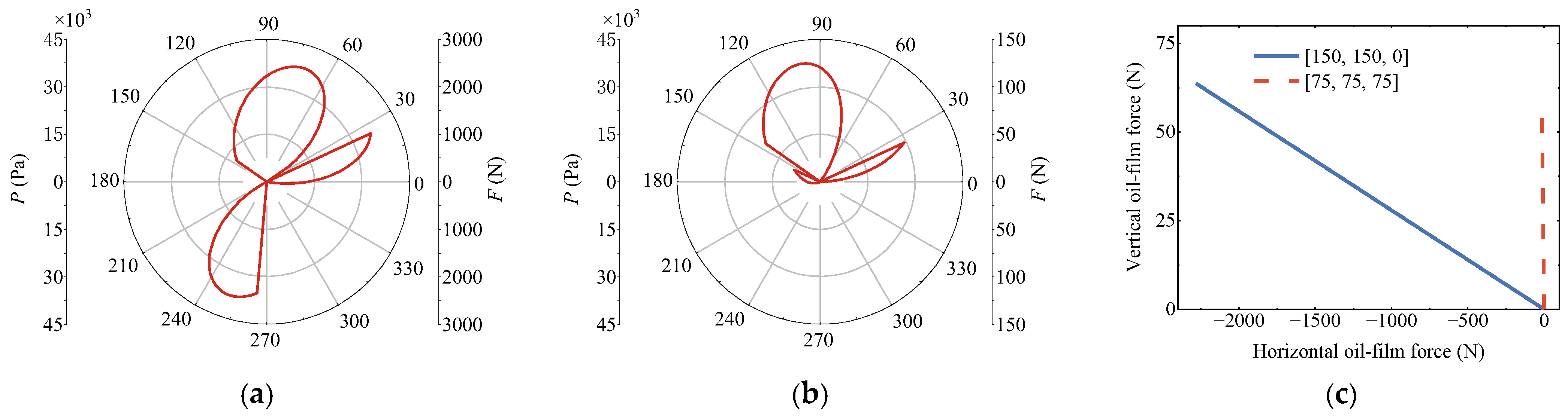
Figure 7 presents polar diagrams illustrating the oil film pressure distributions within the SSFD. For the actuation voltage case of [U1, U2, U3] = [150, 150, 0] V, the circumferential pressure field concentrates mainly over the first and third quadrants. By comparison, when [U1, U2, U3] = [75, 75, 75] V, the pressure field shifts toward the first and second quadrants, along with variations in the oil film forces. The PZT permits separate tuning of the oil film over every bearing pad via voltage modulation, which enables partitioned control. Such functionality empowers the SSFD to generate tailored oil film forces on demand.
Figure 7.
Oil film pressure distribution and oil film force with εi = 0.4. (a) [U1, U2, U3] = [150, 150, 0]. (b) [U1, U2, U3] = [75, 75, 75] V. (c) Oil film force.
3.2. Oil Film Force
The bearing pad carrying the peak hydrodynamic pressure is defined as the primary bearing pad. To comprehensively investigate the tunable behaviors of the SSFD, four distinct operating cases are designed:
Case 1: The primary bearing pad has a voltage of 0 V, while the voltage of the other bearing pads is UV.
Case 2: The voltage for the bearing pad preceding the primary bearing pad in the rotor’s precession direction is 0 V, while the voltage for the remaining bearing pads is UV.
Case 3: The voltage for the bearing pad succeeding the primary bearing pad in the rotor’s precession direction is 0 V, while the voltage for the remaining bearing pads is UV.
Case 4: All bearing pads have a voltage of UV.
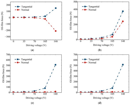
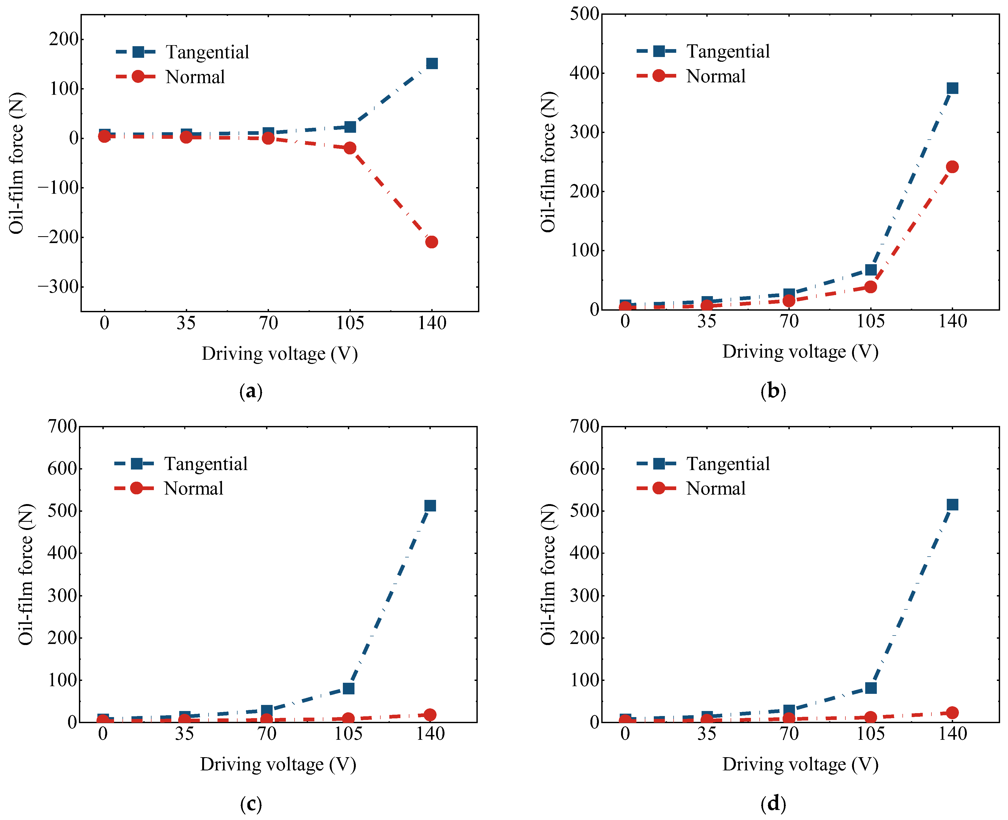
This subsection examines the evolutions of tangential and normal oil film forces generated by the SSFD against the actuation voltage, as plotted in Figure 8. Under Case 1, tangential oil film forces remain positive over the entire voltage range and rise monotonically with growing voltage, which improves the damping performance of the SSFD. By contrast, normal oil film forces decline progressively as the applied voltage rises. At 140 V, a notable shift occurs: the changes in both force components become more pronounced, and the normal oil film force drops below zero, resulting in a softening effect on the rotor support. In Case 2, both tangential and normal oil film forces rise with increasing voltage, each showing a substantial increase at 140 V. For Cases 3 and 4, the tangential oil film force follows a trend similar to that of Case 2, increasing with voltage, while the normal oil film force remains relatively unchanged. At 140 V, Case 4 exhibits the highest tangential oil film force, whereas Case 1 shows the lowest normal oil film force. A cross-case comparison demonstrates that the primary bearing pad exerts a pronounced effect on both the tangential and the normal oil film forces of the SSFD. Tuning the forward segment of the primary bearing pad effectively suppresses the normal oil film force. These findings reveal that the contribution to tangential and normal oil film forces is governed by the selected bearing pad for actuation. Reducing the normal oil film force while raising the tangential oil film force enables attenuation of nonlinear vibrations of the rotor system.
Figure 8.
Tangential and normal oil film forces varying with driving voltage for Cases 1 to 4 with εi = 0.3. (a) Case 1. (b) Case 2. (c) Case 3. (d) Case 4.
4. Nonlinear Dynamic Analysis of the SSFD-Rotor System
This subsection investigates the nonlinear dynamic responses of the SSFD-rotor system and compares them with those of a SFD-rotor system. The differences between the SSFD-rotor system and the SFD-rotor system are as follows: the pad of the SSFD can move radially under PZT actuation, and the driving voltage applied to the PZT is 150 V. All other parameters, including the initial oil film clearance, oil film width, oil viscosity, rotor properties, bearing parameters, squirrel-cage elastic support parameters, and operating conditions, are kept identical for both configurations in the analysis. An unbalanced mass moment “Me” was applied to the disk at node 6. Detailed parameters of the SSFD are given in Section 2.3.
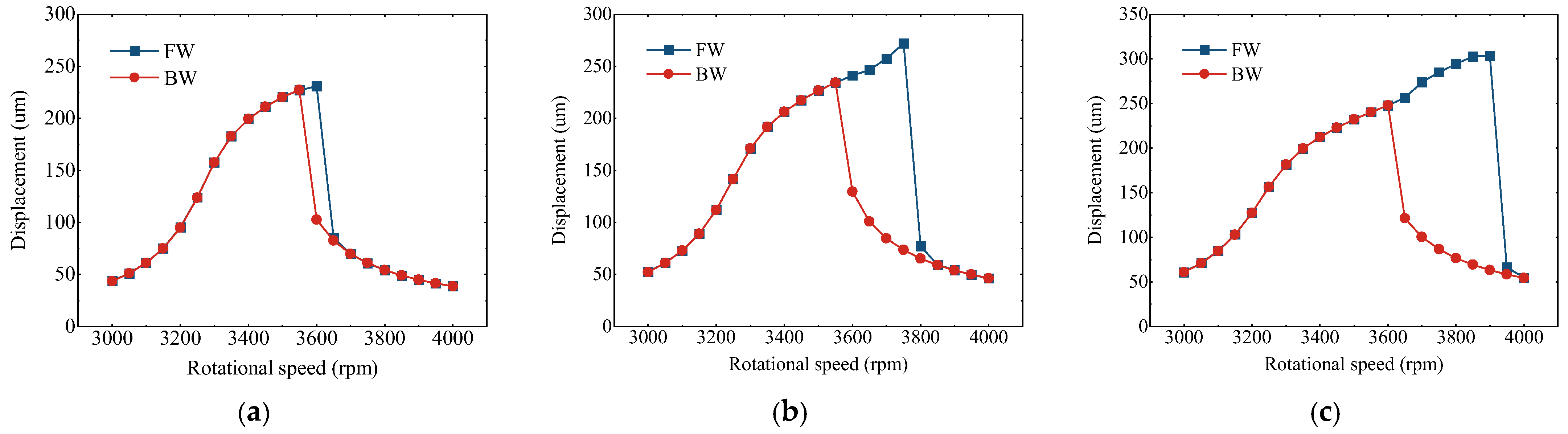
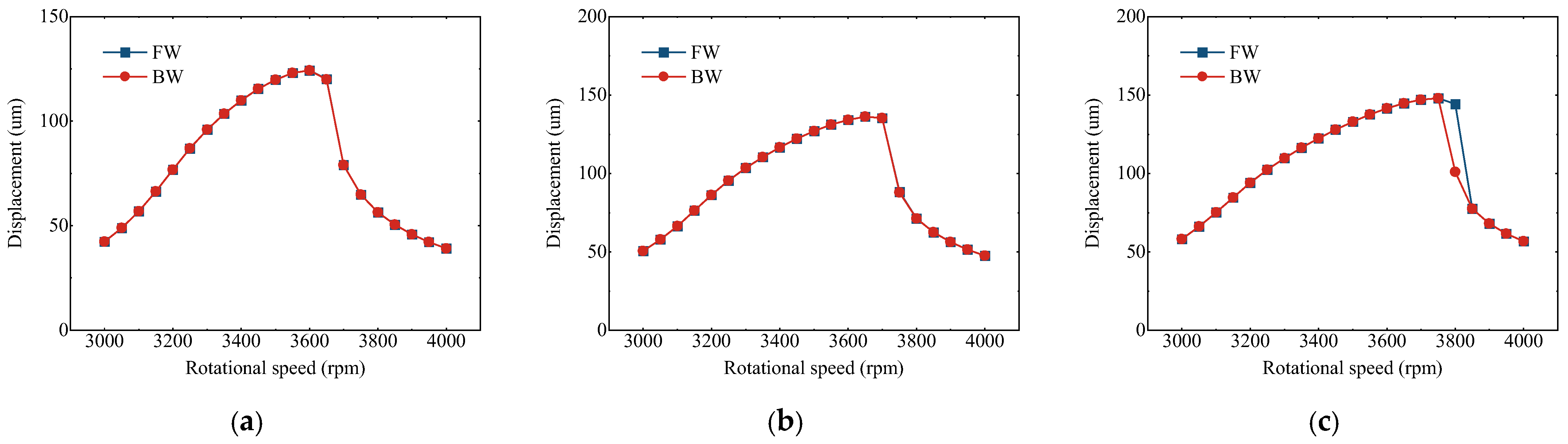
Figure 9 shows the lateral vibration response of the SFD-rotor system. The curves labeled “FW” and “BW” represent the rotor behavior during speed-up and speed-down, respectively. The system exhibits a jump phenomenon within the resonance region: during acceleration, the rotor initially follows a large orbit before abruptly jumping to a smaller one; during deceleration, it initially traces a small orbit before jumping to a larger one. This behavior occurs because near the critical speed the vibration amplitude increases, leading to greater eccentricity of the SFD and a nonlinear increase in stiffness. As the imbalance grows, the multi-solution interval widens, owing to further-increased eccentricity near the critical speed. Moreover, the increased stiffness raises the rotor critical speed, shifting the jump phenomenon to a higher rotational speed. Figure 10 illustrates the vibration response of the SSFD-rotor system. A jump phenomenon is observed only at the highest unbalanced mass moment (Me = 1.4 kg·mm), and the region between jump points is relatively narrow. Compared with the SFD, the SSFD nearly completely suppresses the jump phenomenon, thereby effectively attenuating the nonlinear dynamic responses.
Figure 9.
The lateral vibration of SFD-rotor system varying with the rotating speed under different imbalances. (a) Me = 1.0 kg·mm. (b) Me = 1.2 kg·mm. (c) Me = 1.4 kg·mm.
Figure 10.
The lateral vibration of SSFD-rotor system varying with the rotating speed under different imbalances. (a) Me = 1.0 kg·mm. (b) Me = 1.2 kg·mm. (c) Me = 1.4 kg·mm.
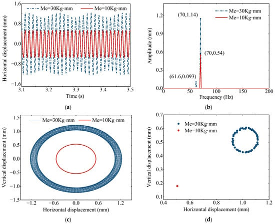
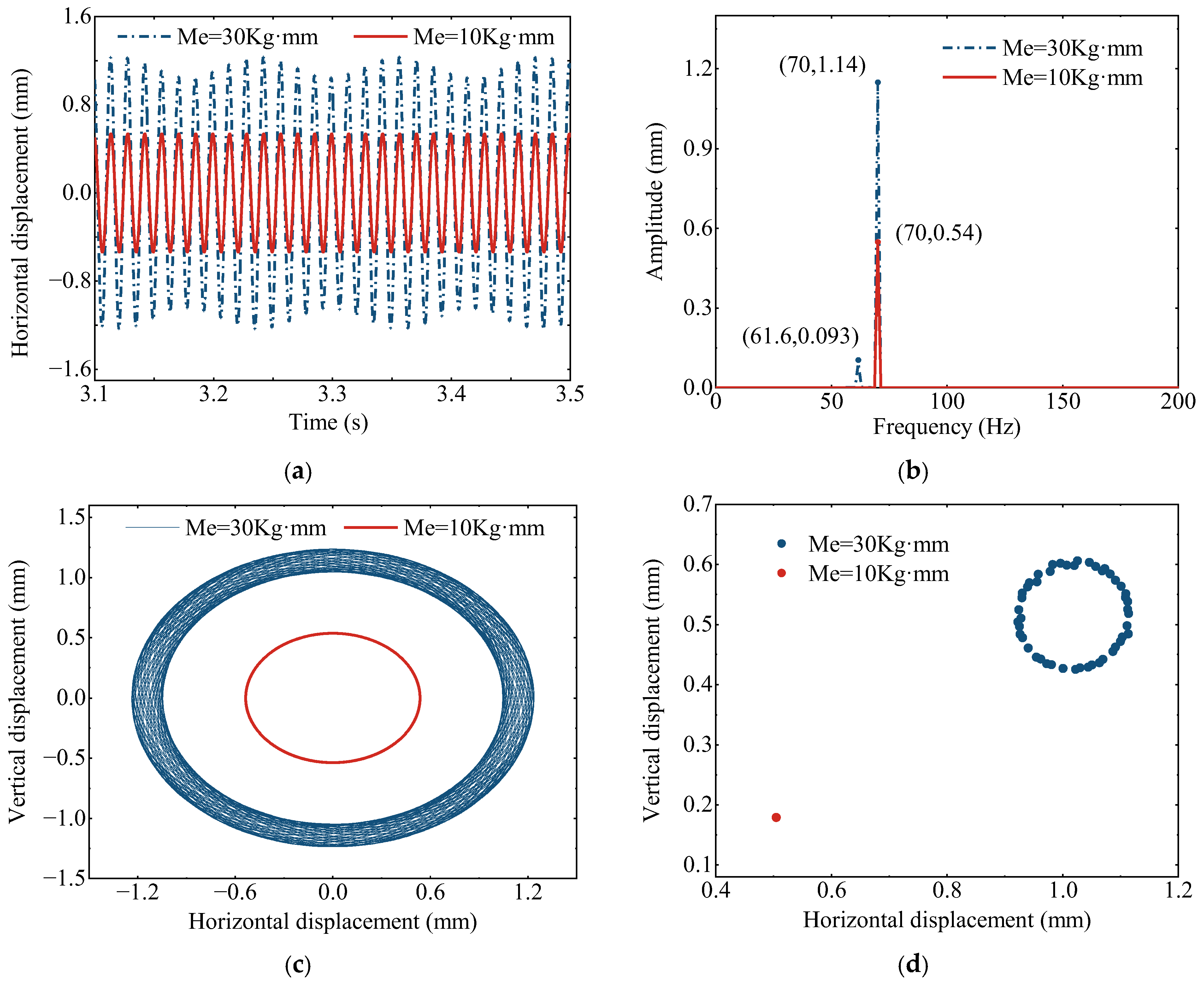
Figure 11 illustrates the vibration response of the SSFD-rotor system. At Me = 10 kg·mm, the system exhibits periodic motion: only the fundamental frequency component appears in the spectrum, the orbital trajectory is circular, and the Poincaré map features a single isolated point. When the imbalance rises to Me = 30 kg·mm, the motion becomes quasi-periodic, resulting in a more complex orbit. Subharmonic components are observed in the frequency spectrum, and a closed curve appears on the Poincaré map. These results reveal that, under the present operating conditions, the rotor vibration transitions from periodic to quasi-periodic as the imbalance increases.
Figure 11.
The vibration response of the SSFD-rotor system when Me = 30 kg·mm and Me = 10 kg·mm with the rotating speed = 4200 rpm. (a) Vibration response. (b) Spectrum. (c) Orbital trajectory. (d) Poincaré map.
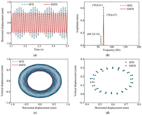
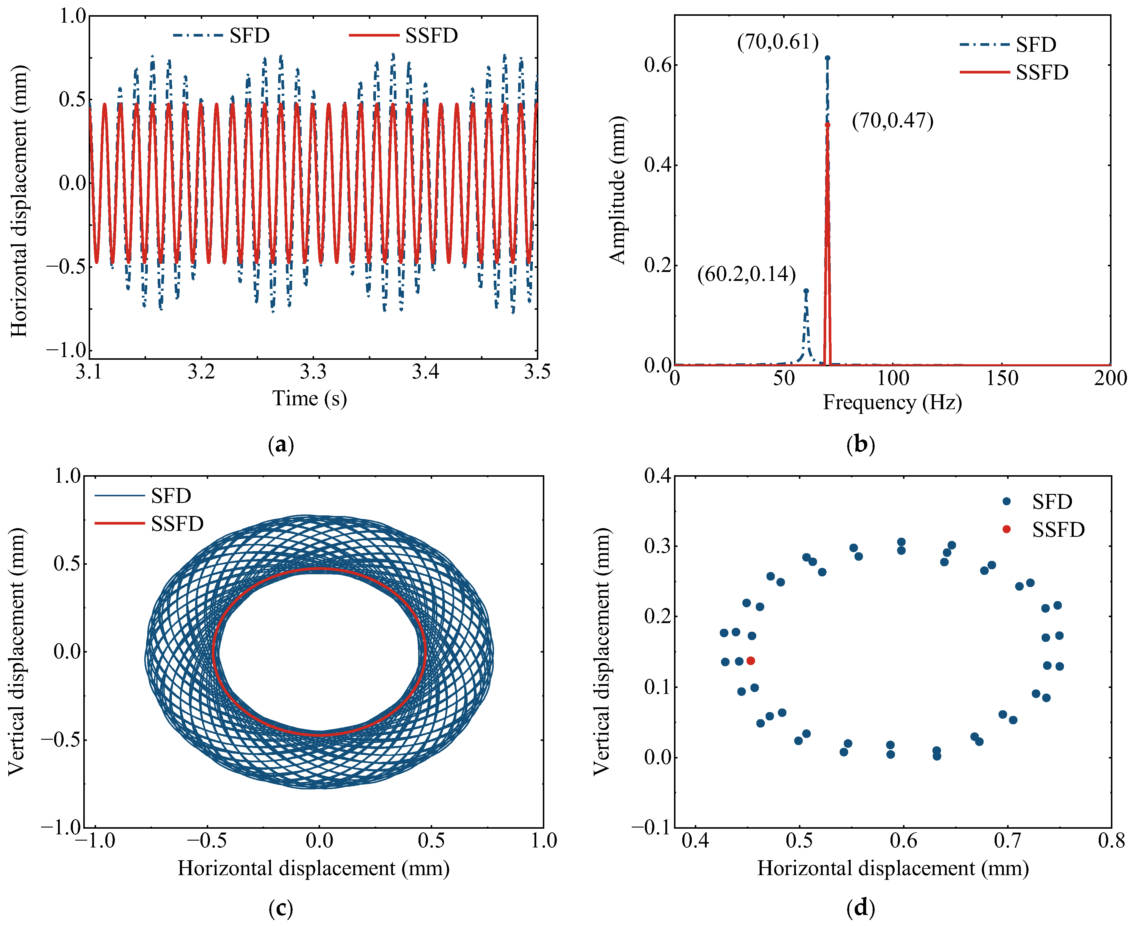
For a more comprehensive comparison between the SSFD-rotor and SFD-rotor systems, Figure 12 presents their dynamic responses at Me = 8 kg·mm. The SSFD-rotor system exhibits an elliptical orbit, a Poincaré map with a single isolated point, and a lower fundamental frequency amplitude than the SFD-rotor system. In contrast, the SFD-rotor system presents a more irregular orbital trajectory, with scattered points visible on the Poincaré map.
Figure 12.
The vibration response of SFD-rotor system and SSFD-rotor system with the rotating speed = 4200 rpm, and Me = 8 kg·mm. (a) Vibration response. (b) Spectrum. (c) Orbital trajectory. (d) Poincaré map.
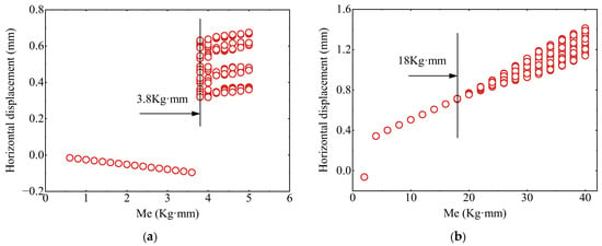
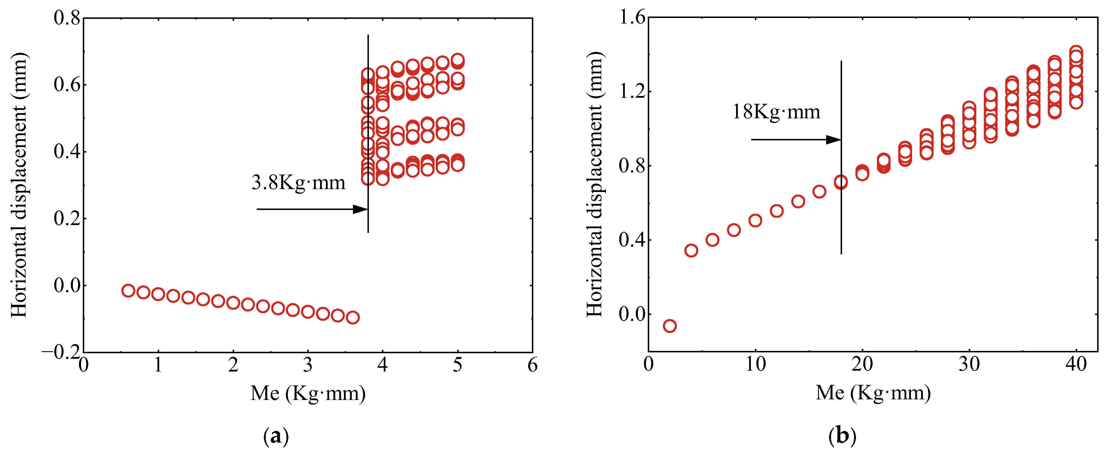
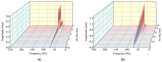
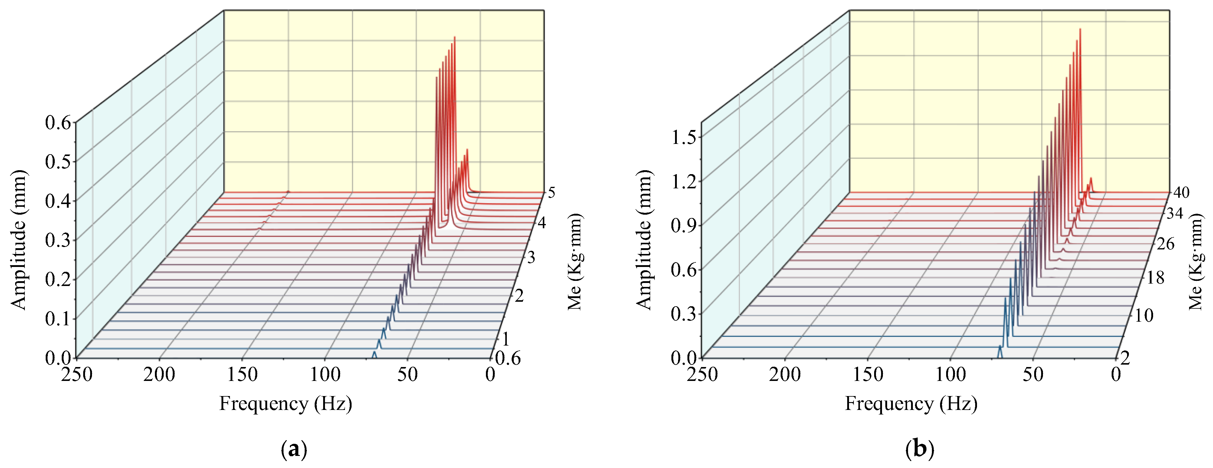
Figure 13 and Figure 14 illustrate the bifurcation characteristics and 3D spectral responses of the two rotor systems. For the SSFD-rotor configuration, periodic vibration persists under imbalance values less than 18 kg·mm, and only the fundamental harmonic is captured in its spectral response. When the imbalance exceeds 18 kg·mm, the system begins to exhibit nonlinear phenomena, accompanied by the emergence of subharmonic components in the spectrum. In contrast, the SFD-rotor system shows bifurcation behavior once the imbalance surpasses 3.8 kg·mm, along with the appearance of irrational frequency components. In comparison to the SFD-rotor system, the SSFD configuration demonstrates enhanced stability under increasing imbalance conditions.
Figure 13.
Bifurcation diagrams of horizontal vibration response of Node 6 varying with the imbalance when the rotating speed = 4200 rpm. (a) SFD-rotor system. (b) SSFD-rotor system.
Figure 14.
Spectral waterfall diagram of horizontal vibration response of Node 6 when the rotating speed = 4200 rpm. (a) SFD-rotor system. (b) SSFD-rotor system.
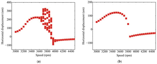
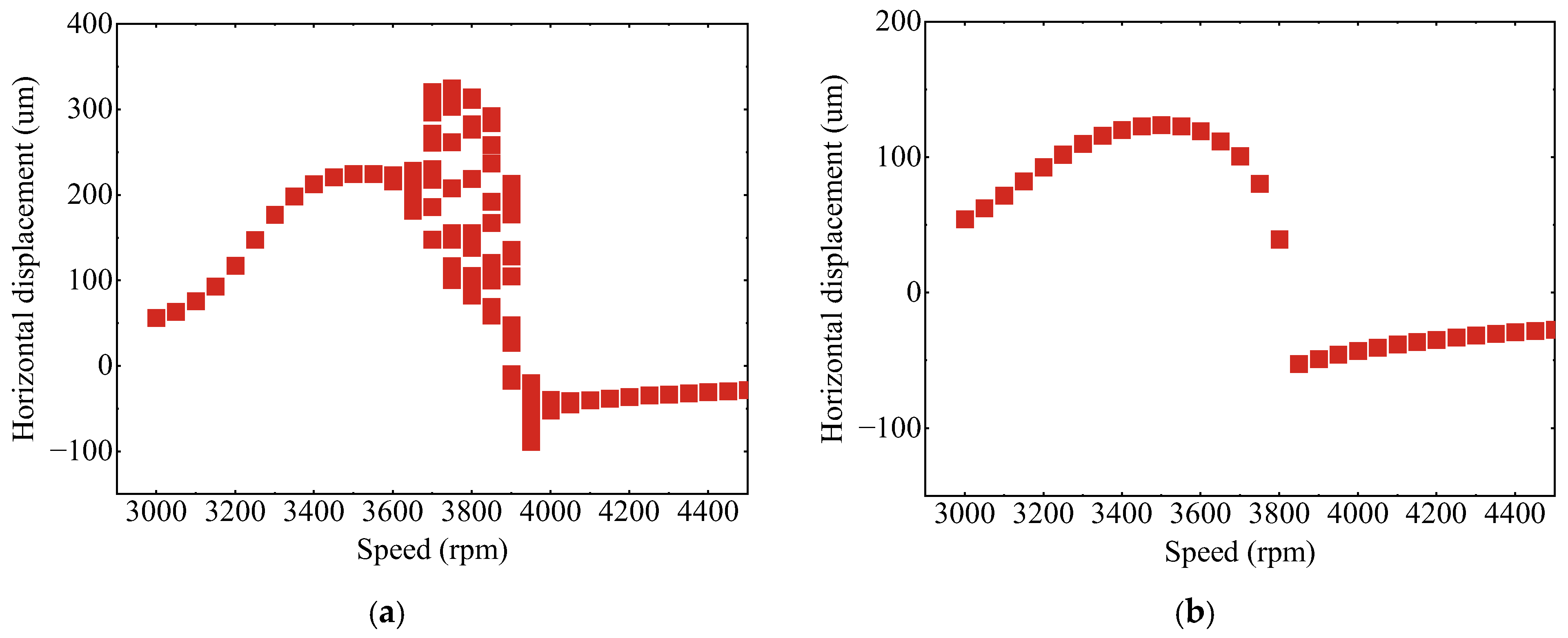
Figure 15 presents the bifurcation diagrams of the horizontal response at Node 6 versus rotational speed. As shown in Figure 15a, the SFD-rotor system initially undergoes periodic motion, transitions to quasi-periodic motion between 3650 and 4050 rpm, and eventually returns to periodic motion at higher speeds. In contrast, the SSFD-rotor system maintains periodic motion throughout the entire speed range, as seen in Figure 15b. A contrast between the two subplots reveals that the SFD-supported rotor readily develops quasi-periodic vibrations around resonance, while the SSFD counterpart maintains periodic response across an extended speed interval. These observations verify that the SSFD can mitigate undesirable nonlinear dynamic responses of rotors.
Figure 15.
Bifurcation diagrams of horizontal vibration response of Node 6 varying with the speed when Me = 1.4 kg·mm. (a) SFD-rotor system. (b) SSFD-rotor system.
5. Conclusions
This work develops an innovative partitioned oil film control strategy. PZTs are utilized to squeeze the oil film across distinct circumferential regions, thereby modulating its tangential and normal hydrodynamic forces. The method’s inhibitory effect on nonlinear vibrational behaviors is analyzed and discussed.
- (1)
- Governing equations for the rotor support assembly were formulated and assembled into the global dynamic framework. Comparisons between measured data and numerical predictions reveal that raising the voltage of PZTs suppresses transient resonance responses of this rotor, which confirms the reliability and applicability of the established formulation.
- (2)
- The primary bearing pad dominates both tangential and normal hydrodynamic force components generated within the SSFD. Conversely, tuning pads with lower oil film pressure produces a negative normal hydrodynamic force, which effectively reduces the rotor support stiffness.
- (3)
- Compared to the SFD-rotor system, the SSFD-rotor system exhibits the jump phenomenon only under higher unbalance levels, and the region between the jump points is narrower. As the unbalance increases, sub-synchronous vibrations occur later in the SSFD-rotor system, and the range of non-synchronous motion is reduced. With increasing rotational speed, the SSFD-rotor system maintains periodic motion over a wider range. The proposed partitioned oil film control method effectively suppresses the nonlinear vibration level of the rotor system.
This study has not considered the cavitation phenomenon in the SSFD or the nonlinear contact forces within the rolling bearings. Future work will focus on advancing the hydrodynamic formulation for the SSFD, refining the rolling bearing representation, improving the control scheme, and exploring its influences on the nonlinear vibrational characteristics of rotor assemblies.
Author Contributions
Y.Z.: Conceptualization, Methodology, Software, Data curation, Validation, Formal analysis, Investigation, Writing—original draft. Z.M.: Edit draft. X.T.: Investigation. L.W.: Investigation. X.Z.: Investigation. R.L.: Investigation. All authors have read and agreed to the published version of the manuscript.
Funding
This work was supported by the Hunan Natural Science Foundation Project (Grant No. 2025JJ60317), the Research Project Funded by the Department of Education of Hunan Province (Grant No. 25B0204), the Hunan Provincial Natural Science Foundation of China (Grant No. 2025JJ80369), the Hunan Institute of Engineering Doctoral Research Foundation (Grant No. 25RC024), and the Hunan Provincial College Students’ Innovation and Entrepreneurship Training Program (Grant No. 6202).
Data Availability Statement
The data are available from the corresponding author upon request.
Acknowledgments
This work was supported by Guangfu Bin.
Conflicts of Interest
The authors declare that they have no known competing financial interests or personal relationships that could have appeared to influence the work reported in this paper.
References
- Zeidan, F.Y.; Andres, L.S.; Vance, J.M. Design and application of squeeze film dampers in rotating machinery. In Proceedings of the 25th Turbomachinery Symposium, College Station, TX, USA, 16–19 September 1996. [Google Scholar]
- Gunter, E.; Barrett, L.; Allaire, P. Design of nonlinear squeeze-film dampers for aircraft engines. J. Lubr. Tech. 1977, 99, 57–64. [Google Scholar] [CrossRef] [Scilit]
- Mohan, S.; Hahn, E. Design of squeeze film damper supports for rigid rotors. J. Eng. Ind. 1974, 96, 976–982. [Google Scholar] [CrossRef] [Scilit]
- Bin, G.; Li, C.; Li, J.; Chen, A. Erosion-damage-induced vibration response of aero-gas generator rotor system. Mech. Syst. Sig. Process. 2023, 195, 110298. [Google Scholar] [CrossRef] [Scilit]
- Li, C.; Bin, G.; Li, J.; Liu, Z. Study on the erosive wear of the gas-solid flow of compressor blade in an aero-turboshaft engine based on the Finnie model. Tribol. Int. 2021, 163, 107197. [Google Scholar] [CrossRef] [Scilit]
- Zhu, C.S.; Robb, D.A.; Ewins, D.J. Analysis of the multiple-solution response of a flexible rotor supported on non-linear squeeze film dampers. J. Sound Vib. 2002, 252, 389–408. [Google Scholar] [CrossRef] [Scilit]
- Han, Z.F.; Ding, Q.; Zhang, W. Dynamical analysis of an elastic ring squeeze film damper-rotor system. Mech. Mach. Theory. 2019, 131, 406–419. [Google Scholar] [CrossRef] [Scilit]
- Taylor, D.; Kumar, B. Nonlinear response of short squeeze film dampers. J. Lubr. Tech. 1980, 102, 51–58. [Google Scholar] [CrossRef] [Scilit]
- Zhao, J.Y.; Linnett, I.W.; McLean, L.J. Stability and Bifurcation of Unbalanced Response of a Squeeze Film Damped Flexible Rotor. J. Tribol. 1994, 116, 361–368. [Google Scholar] [CrossRef] [Scilit]
- Zhao, J.; Hahn, E. Eccentric operation and blade-loss simulation of a rigid rotor supported by an improved squeeze film damper. J. Tribol. 1995, 117, 490–497. [Google Scholar] [CrossRef] [Scilit]
- Zeidan, F.; Vance, J. Cavitation and air entrainment effects on the response of squeeze film supported rotors. J. Tribol. 1990, 112, 347–353. [Google Scholar] [CrossRef] [Scilit]
- Nikolajsen, J.; Holmes, R. Investigation of squeeze-film isolators for the vibration control of a flexible rotor. J. Mech. Eng. Sci. 1979, 21, 247–252. [Google Scholar] [CrossRef] [Scilit]
- Sykes, J.; Holrnes, R. The effects of bearing misalignment on the non-linear vibration of aero-engine rotor–damper assemblies. Proc. Inst. Mech. Eng. Part G J. Aerosp. Eng. 1990, 204, 83–99. [Google Scholar] [CrossRef] [Scilit]
- Holmes, R.; Dogan, M. Investigation of a rotor bearing assembly incorporating a squeeze-film damper bearing. J. Mech. Eng. Sci. 1982, 24, 129–137. [Google Scholar] [CrossRef] [Scilit]
- Inayat-Hussain, J.I. Bifurcations in the response of a flexible rotor in squeeze-film dampers with retainer springs. Chaos Solitons Fractals 2009, 39, 519–532. [Google Scholar] [CrossRef] [Scilit]
- Bonello, P.; Brennan, M.J.; Holmes, R. Non-linear modelling of rotor dynamic systems with squeeze film dampers—An efficient integrated approach. J. Sound Vib. 2002, 249, 743–773. [Google Scholar] [CrossRef] [Scilit]
- Chen, H.; Hou, L.; Chen, Y.; Yang, R. Dynamic characteristics of flexible rotor with squeeze film damper excited by two frequencies. Nonlinear Dyn. 2017, 87, 2463–2481. [Google Scholar] [CrossRef] [Scilit]
- Chen, X.; Ren, G.; Gan, X. Dynamic behavior of a flexible rotor system with squeeze film damper considering oil-film inertia under base motions. Nonlinear Dyn. 2021, 106, 3117–3145. [Google Scholar] [CrossRef] [Scilit]
- Luo, Z.; Wang, J.W.; Tang, R.; Wang, D.Y. Research on vibration performance of the nonlinear combined support-flexible rotor system. Nonlinear Dyn. 2019, 98, 113–128. [Google Scholar] [CrossRef] [Scilit]
- Rezvani, M.; Hahn, E. Floating ring squeeze film damper: Theoretical analysis. Tribol. Int. 2000, 33, 249–258. [Google Scholar] [CrossRef] [Scilit]
- Zhou, H.L.; Feng, G.Q.; Luo, G.H.; Ai, Y.T.; Sun, D. The dynamic characteristics of a rotor supported on ball bearings with different floating ring squeeze film dampers. Mech. Mach. Theory. 2014, 80, 200–213. [Google Scholar] [CrossRef] [Scilit]
- Hong, J.; Deng, Y.; Zhang, D.Y. Dynamic design method of elastic ring squeeze film damper. J. Beijing Univ. Aeron. Astron 2006, 32, 649–653. (In Chinese) [Google Scholar]
- Han, Z.; Ma, Z.; Zhang, W.; Han, B.; Ding, Q. Dynamic analysis of an elastic ring squeeze film damper supported rotor using a semi-analytic method. Eng. Appl. Comput. Fluid Mech. 2020, 14, 1263–1278. [Google Scholar] [CrossRef] [Scilit]
- De Santiago, O.; San Andre’s, L.; Oliveras, J. Imbalance response of a rotor supported on open-ends integral squeeze film dampers. J. Eng. Gas. Turbines Power. 1999, 121, 718–724. [Google Scholar] [CrossRef] [Scilit]
- Ertas, B.; Cerny, V.; Kim, J.; Polreich, V. Stabilizing a 46 MW multistage utility steam turbine using integral squeeze film bearing support dampers. J. Eng. Gas. Turbines Power. 2015, 137, 052506. [Google Scholar] [CrossRef] [Scilit]
- Zheng, W.; Pei, S.; Zhang, Q.; Hong, J. Experimental and Theoretical Results of the Performance of Controllable Clearance Squeeze Film Damper on Reducing the Critical Amplitude. Tribol. Int. 2021, 166, 107155. [Google Scholar] [CrossRef] [Scilit]
- El-Shafei, A. Experimental and analytical investigation of hybrid squeeze film dampers. J. Eng. Gas. Turbines Power. 1993, 115, 353–359. [Google Scholar] [CrossRef] [Scilit]
- El-Shafei, A. Active control algorithms for the control of rotor vibrations using hybrid squeeze film dampers. J. Eng. Gas. Turbines Power. 2002, 124, 598–607. [Google Scholar] [CrossRef] [Scilit]
- Morishita, S.; Mitsui, J.I. Controllable squeeze film damper (an application of electro-rheological fluid). J. Vib. Acoust. 1992, 114, 354–357. [Google Scholar] [CrossRef] [Scilit]
- Lim, S.; Park, S.-M.; Kim, K.-I. AI vibration control of high-speed rotor systems using electrorheological fluid. J. Sound Vib. 2005, 284, 685–703. [Google Scholar] [CrossRef] [Scilit]
- Wang, J.; Zhang, X.; Liu, Y.; Qin, Z.; Ma, L.; Chu, F. Rotor vibration control via integral magnetorheological damper. Int. J. Mech. Sci. 2023, 252, 108362. [Google Scholar] [CrossRef] [Scilit]
- Wang, J.; Liu, Y.; Qin, Z.; Ma, L.; Chu, F. Dynamic performance of a novel integral magnetorheological damper-rotor system. Mech. Syst. Sig. Process. 2022, 172, 109004. [Google Scholar] [CrossRef] [Scilit]
- Lu, Q.; Li, C.; Zhang, Y.; Fang, H.; Bin, G. Study on the vibration control method of a turboshaft engine rotor based on piezoelectric squeeze film damper oil film clearance. Mech. Sci. 2023, 14, 237–246. [Google Scholar] [CrossRef] [Scilit]
- Palazzolo, A.; Lin, R.; Alexander, R.; Kascak, A.; Montague, J. Test and theory for piezoelectric actuator-active vibration control of rotating machinery. J. Vib. Acoust. 1991, 113, 167–175. [Google Scholar] [CrossRef] [Scilit]
- Tůma, J.; Šimek, J.; Škuta, J.; Los, J. Active vibrations control of journal bearings with the use of piezoactuators. Mech. Syst. Sig. Process. 2013, 36, 618–629. [Google Scholar] [CrossRef] [Scilit]
- Jungblut, J.; Haas, J.; Rinderknecht, S. A new active balancing device utilizing rotating piezo actuators. Mech. Syst. Sig. Process. 2022, 181, 109521. [Google Scholar] [CrossRef] [Scilit]
- Jungblut, J.; Haas, J.; Rinderknecht, S. Active vibration control of an elastic rotor by using its deformation as controlled variable. Mech. Syst. Sig. Process. 2022, 165, 108371. [Google Scholar] [CrossRef] [Scilit]
- Simoes, R.; Steffen, J.V.; Hagopian, J.; Mahfoud, J. Modal Active Vibration Control of a Rotor Using Piezoelectric Stack Actuators. J. Vib. Control 2007, 13, 45–64. [Google Scholar] [CrossRef] [Scilit]
- Zhang, Y.; Bin, G.; Lu, X. Piezoelectric driven split pad squeeze film damper for the suppression of sudden unbalanced vibrations in rotor system. J. Sound Vib. 2024, 578, 118331. [Google Scholar] [CrossRef] [Scilit]
- Zhang, Y.; Bin, G.; Xu, Y. Study on vibration suppression of an aero-engine rotor system with adjustable oil film thickness driven by piezoelectric actuator through critical speed. Tribol. Int. 2024, 193, 109447. [Google Scholar] [CrossRef] [Scilit]

Disclaimer/Publisher’s Note: The statements, opinions and data contained in all publications are solely those of the individual author(s) and contributor(s) and not of MDPI and/or the editor(s). MDPI and/or the editor(s) disclaim responsibility for any injury to people or property resulting from any ideas, methods, instructions or products referred to in the content. |
© 2026 by the authors. Licensee MDPI, Basel, Switzerland. This article is an open access article distributed under the terms and conditions of the Creative Commons Attribution (CC BY) license.