


Abstract
Aiming at preload transfer, spatial deviation and non-uniform load distribution in multi-bearing groups of spindles, the conventional superposition of single-bearing stiffness cannot accurately reflect mechanical behaviours. Taking ball bearing groups as the research object, this paper established a preload model for back-to-back duplex bearings. The local–global displacement mapping and stiffness assembly relation between spindle and bearings are constructed. A local–global nested iterative algorithm is adopted with consideration of clearance and nonlinear ball–raceway contact-loss. Test stiffness is obtained by differentiating measured load-displacement data for model validation. Comparative analyses are conducted on stiffness, contact angle and contact load of duplex, triplex and quadruplex bearings under different configurations. The findings demonstrate that the overall stiffness of a bearing group depends on the number of bearings, their arrangement within the assembly, and the direction of the applied load. Furthermore, individual bearings do not share the load equally, and contact conditions deteriorate progressively as bearing contacts are lost in succession.
1. Introduction
As the core component of cutting equipment, the precision spindle’s mechanical behaviour is largely determined by its supporting bearing groups, which directly govern system stiffness, rotational accuracy and service life [1,2]. Angular-contact ball bearings can sustain combined axial–radial loads and allow convenient preload regulation, so they are widely employed in back-to-back or face-to-face matched configurations for boring-spindle supports [2]. Preload eliminates internal clearance, yet preload redistribution occurs under external loads. Rolling-element contact status varies, and contact-loss may occur, producing strongly nonlinear stiffness for bearing assemblies [3]. Simple algebraic superposition of individual-bearing stiffness, a common engineering practice, neglects spatial mounting-position effects and uneven internal-load distribution and introduces considerable computational errors [4].
Fundamental static investigations on single ball bearings were carried out abroad at an early stage. Harris [5] and Jones [6] constructed the classical static framework based on Hertz contact theory to describe ball–raceway contact deformation–load relations, which laid the theoretical foundation for subsequent bearing-stiffness calculation. Lim [7,8,9] established an analytical framework for the five-degree-of-freedom stiffness matrix of single bearings and derived primary and cross-coupling stiffness terms. Liew [10] further investigated time-variant stiffness characteristics caused by rolling-element movement. Noel et al. [11] presented fully analytical stiffness matrix expressions with centrifugal-force and gyroscopic-moment effects of rolling elements included. Liu et al. [12] analysed contact-load and contact-angle distributions under combined external loads. Petersen [13] and Li [14] separately studied internal load redistribution induced by local raceway defects. Zhang [15] explored disturbances from ring misalignment on bearing contact performance. Yun [16] constructed a thermo-mechanical coupled dynamic-stiffness model, revealing stiffness evolution under varying preload, rotating speed and temperature, and pointed out that oil-film influence remains limited under light-lubrication conditions. Sheng [17] investigated bearing-stiffness calculation under variable-speed conditions. Yu [18] supplemented single-bearing theory from the perspective of circumferential symmetry.
With advances in spindle technology, research was extended to matched bearing assemblies. Bercea [19,20] derived general load formulas for double-row bearings, laying a foundation for duplex-bearing modelling. Gunduz et al. [21,22] provided analytical stiffness solutions for back-to-back and face-to-face duplex bearings, whose results are widely adopted as benchmark references for model validation. Gu [23] built a duplex-bearing model using coordinate transformation, systematically analysing influences from preload, initial contact angle and overturning moment and comparing performances of two typical mounting arrangements. Lin et al. [24] researched stiffness matrices for preloaded duplex bearings. Yang [25] performed experimental tests to capture stiffness variations under different assembly configurations.
For triplex- and quadruplex-bearing groups, Zhang [26] proposed a general combined-bearing model adopting nested iteration to handle nonlinear contact-loss. Nevertheless, global-coordinate transformation originating from bearing mounting positions on the shaft was not sufficiently considered. Sun [27] analysed internal-load distribution and dynamic-stiffness features for TBT combined bearings. Zhang [28] investigated preload and stiffness properties of assemblies with mixed initial contact angles.
In summary, theories for single and duplex bearings are relatively well established. Still, obvious deficiencies exist for multi-bearing groups with two bearings on each side for spindles. Most models lack complete local-to-global coordinate mapping and ignore coupling effects from mounting positions. Systematic analyses on mixed-contact-angle configurations and sequential in-group contact-loss evolution are insufficient. Experimental validations for multi-bearing groups using stiffness obtained by differentiating load-displacement curves remain rare. This constrains the selection of suitable bearings and the optimisation of bearing-group assembly procedures. To address these gaps, this thesis establishes a static model for bearing groups with two bearings on each side. Global–local displacement mapping and stiffness assembly are implemented. Nested iteration is utilized to cope with rolling-element contact-loss. Experiments are conducted to obtain differentiated tangent stiffness for model validation. Multiple assembly schemes are compared, and mechanisms of stiffness evolution and sequential contact loss are revealed, establishing a theoretical foundation for the appropriate configuration and selection of bearing assemblies in boring spindles.
2. Preload State Analysis of Bearing Groups
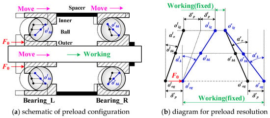
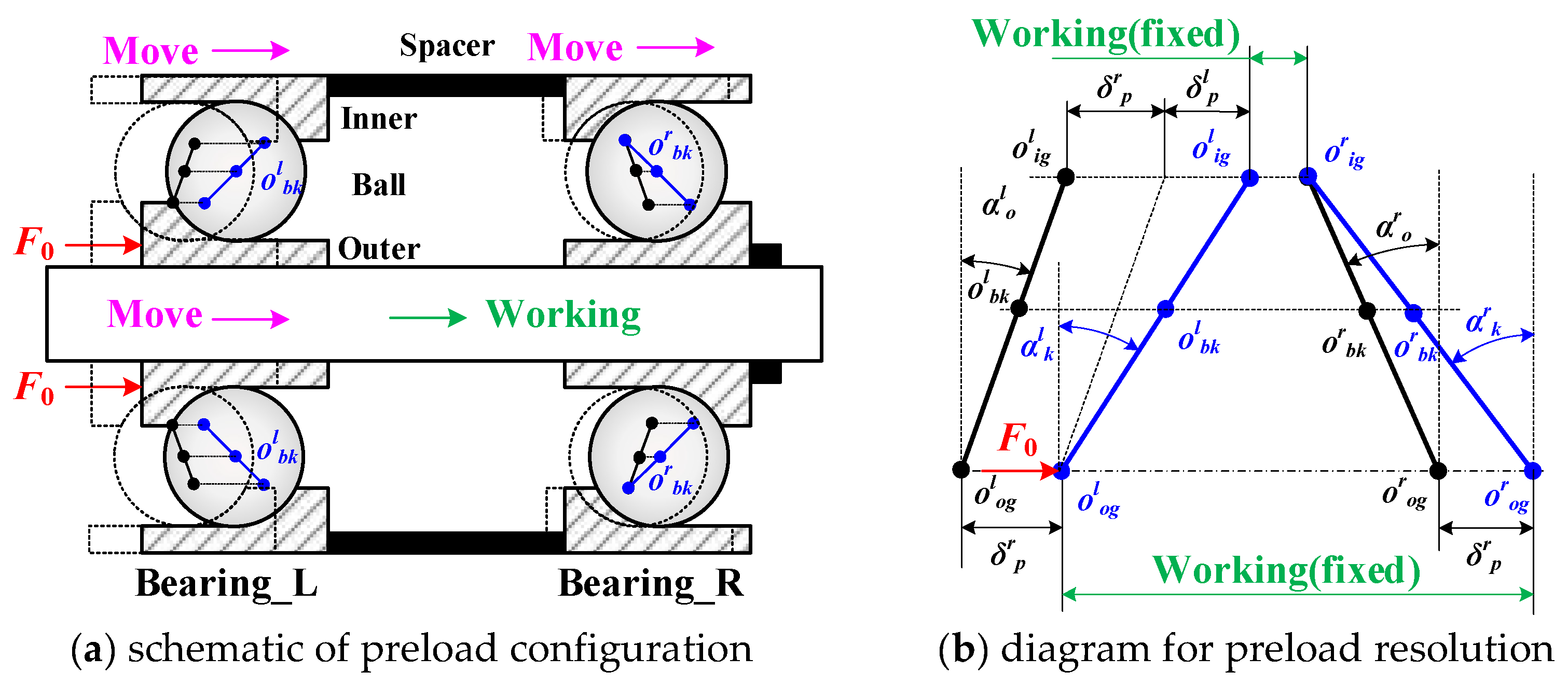
As shown in Figure 1, a pair of back-to-back ball bearings is taken as the research object in this section. Preload is introduced by controlled end-face protrusion. Internal clearance is eliminated, and initial contact deformation is generated inside bearings.
Figure 1.
Numerical interpretation of preload state for ball-bearing group.
Mutual mechanical constraint exists between the two bearings. Axial deformation of one bearing is coupled with that of the other bearing. Such a coupling effect cannot be described by the conventional stiffness superposition method.
When an axial preload F0 is applied to the duplex-bearing group, load equilibrium is satisfied for left and right bearings:
where δlp and δrp denote the axial deformations induced by preload in the left and right bearings, respectively.
For the left-side bearing, the preload force is derived from Hertz contact theory and geometric compatibility of ball–raceway contacts.
The axial preload stiffness of the left bearing is obtained by differentiating F0 with respect to δlp.
Auxiliary variables for the left bearing are defined as:
where Zl is the ball number in the left bearing; rli/o is the curvature radius of inner/outer raceway in the left bearing; Dlw is the ball diameter in the left bearing; and kn is the Hertz contact deflection.
The Newton–Raphson iterative method is used to solve load Equation (2) and obtain the preload compression. It is then substituted into the stiffness matrix Equation (3) to determine the local stiffness matrix of the left bearing. Fortunately, the Jacobian matrix of Equation (2) is exactly Equation (3), which simplifies the solution process.
Similarly, the axial preload stiffness of the right bearing is calculated.
An external axial force Fe is applied in the rightward direction. Equal global axial displacement δa is produced for the whole bearing assembly. Internal deformation is redistributed. The axial displacement of the left bearing is increased. The axial displacement of the right bearing is decreased. Updated deformations of single bearings are written as:
Progressive unloading is observed for the right-side bearing with the growth of δa. Rolling-element contact is lost when contact deformation becomes negative. Load-bearing capacity is no longer provided by the unloaded bearing. This contact-loss nonlinear behaviour cannot be captured by conventional linear superposition.
Preload and deformation solutions from this chapter are adopted as initial conditions for subsequent multi-bearing-group calculation.
3. Operating-Condition Modelling of Bearing Groups
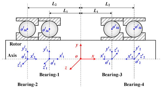
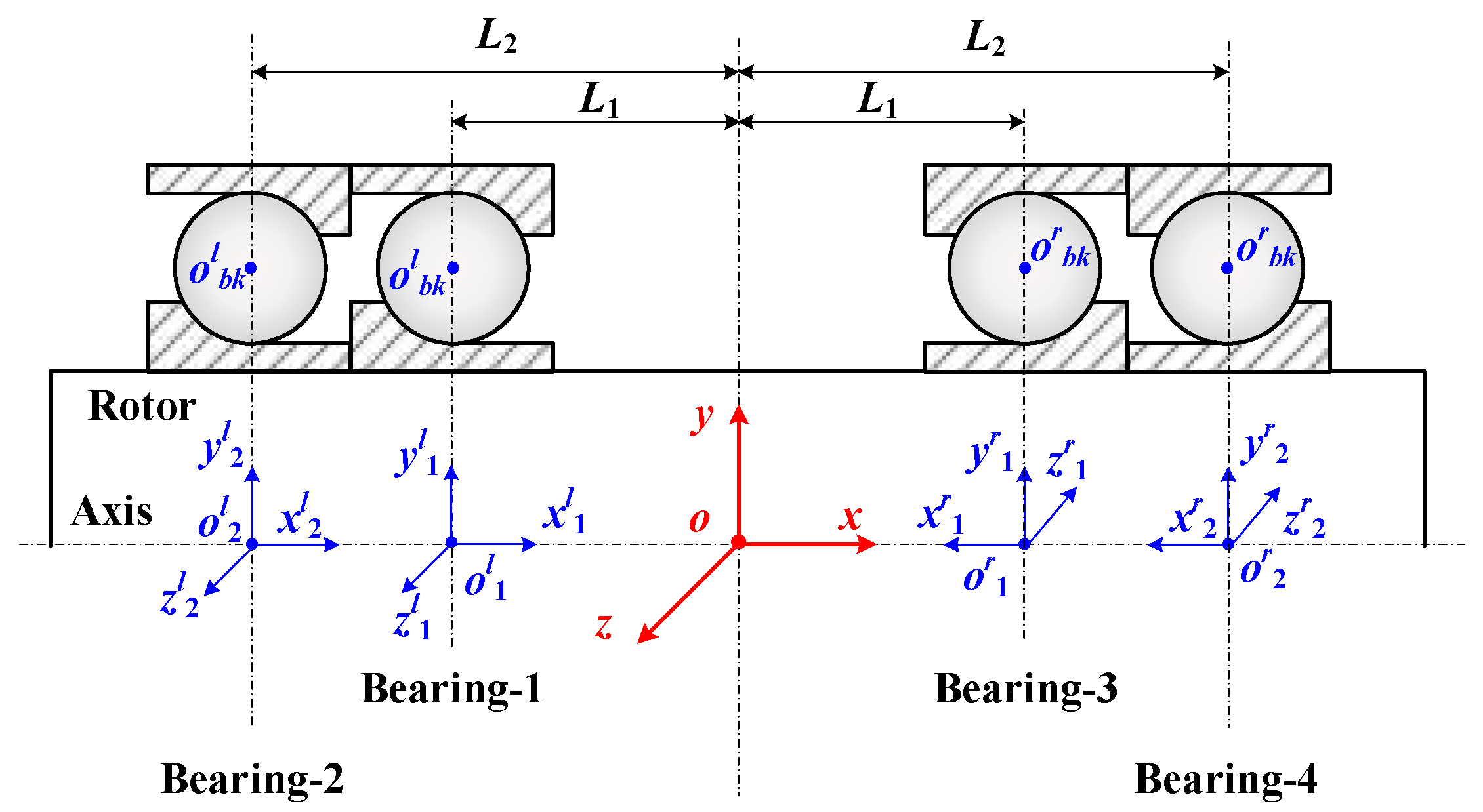
A bearing group with two bearings on the left and two bearings on the right is modelled in this section, as shown in Figure 2. Displacement transfer relations are established. Global shaft displacement is mapped to the local displacement of each single bearing. Local displacement is further transferred to single-bearing nonlinear stiffness. Group-level stiffness is assembled finally. Direct summation of single-bearing stiffness matrices is avoided. Coordinate transformation is implemented between the spindle global frame and each bearing local frame. As this study focuses on bearing-group performance under low- to moderate-speed operating conditions, the effect of rotational speed on bearing stiffness is considered negligible and is therefore excluded from the analysis.
Figure 2.
Modelling diagram for operating conditions of ball-bearing group.
3.1. Displacement Mapping and Group-Load Formulation
Four bearings are arranged along the shaft. Two bearings are installed on the left side, and the other two are installed on the right side. Local displacement vectors of these four bearings are expressed as:
Corresponding load vectors for the four bearings are written as:
Transformation matrices are defined to convert quantities between bearing local frames and the shaft global frame. Nl1 and Nl2 are used for the two left-side bearings, and Nr1 and Nr2 are used for the two right-side bearings, defined as:
The resultant force-moment vector F [Fx, Fy, Fz, My, Mz] at the shaft reference centre is obtained by coordinate transformation:
Local bearing displacements are calculated from the global shaft displacement d (dx, dy, dz, θy, θz]. Initial preload-related deformation terms are superimposed.
The tangent stiffness of the whole bearing group is derived by differentiating the resultant load with respect to global spindle displacement.
Chain-rule differentiation is performed for each bearing term.
The final tangent stiffness matrix of the bearing group is assembled as:
Each term (∂Fi/∂di) represents the tangent stiffness matrix of a single bearing. Its evaluation is explained in the following subsection.
3.2. Single-Bearing Stiffness Matrix
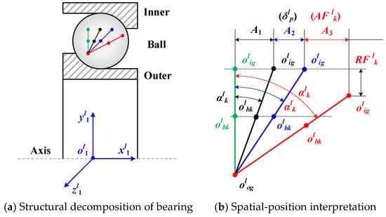
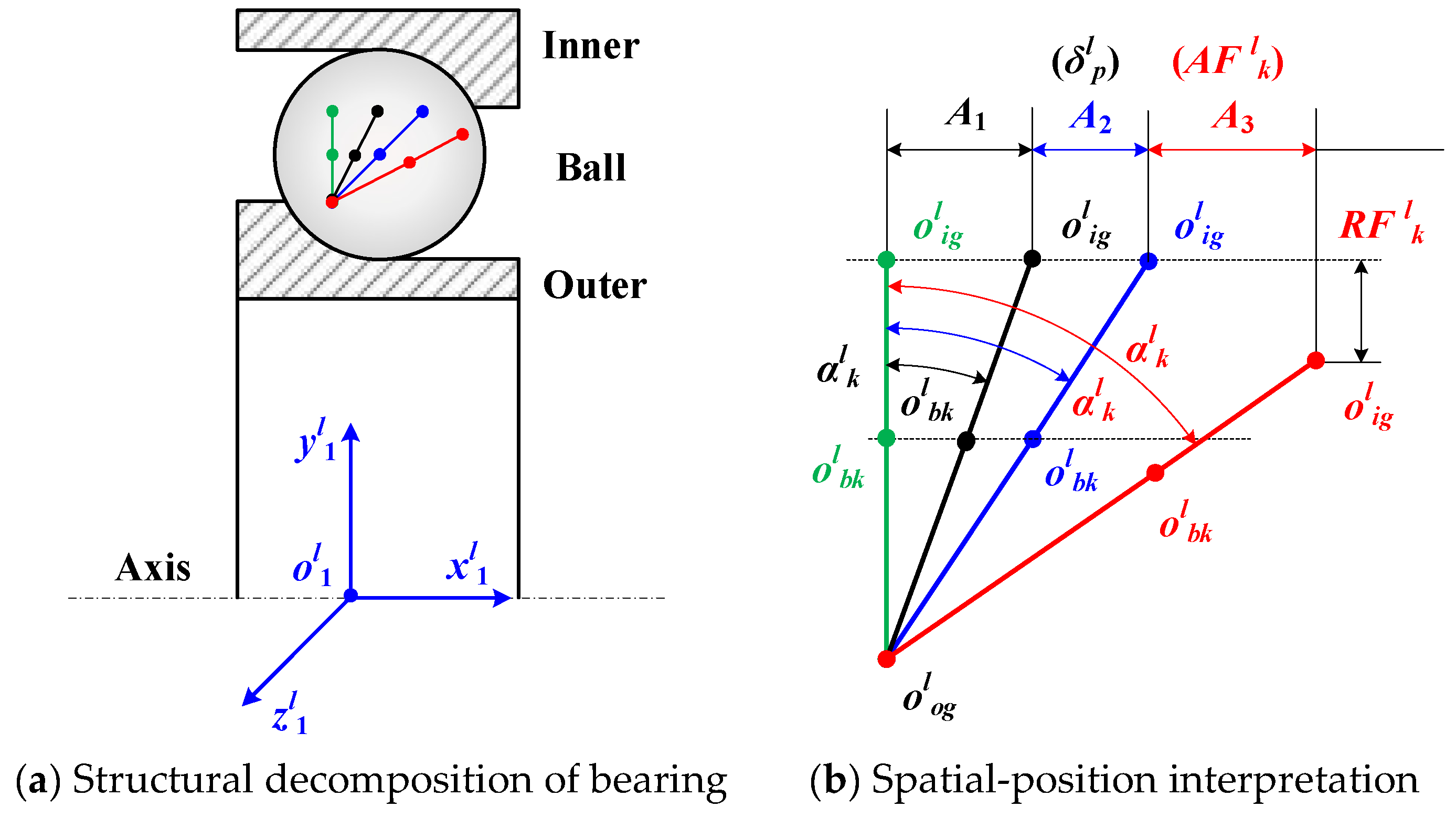
As shown in Figure 3, the left-side bearing is taken as the demonstration example. Four sequential working phases are defined to guarantee numerical stability. The initial clearance state, clearance-elimination phase, preloaded phase and external-loaded operating phase are included.
Figure 3.
Analytical illustration for single-bearing geometry and spatial position.
Axial and radial relative displacements are calculated for the k-th ball:
The working contact angle for the k-th ball is updated:
The deflection between the ball and raceways can be obtained by:
The ball–raceway contact load is computed according to Hertz contact theory:
Contact forces and moments from all rolling elements are summed. The total load vector of the single bearing is obtained.
The tangent stiffness matrix of this bearing is calculated by implicit differentiation, which can be found in Appendix A:
Contact-loss judgement is embedded in computation. Contact loads are set to zero when non-positive contact deformation is detected. Contact angles, individual ball loads and the tangent stiffness matrix are output. These outputs are fed back to the group-level stiffness assembly described in Section 3.1.
3.3. Local–Global Nested Iteration
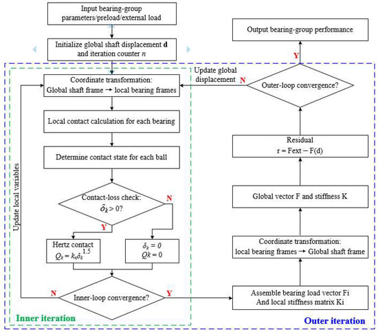
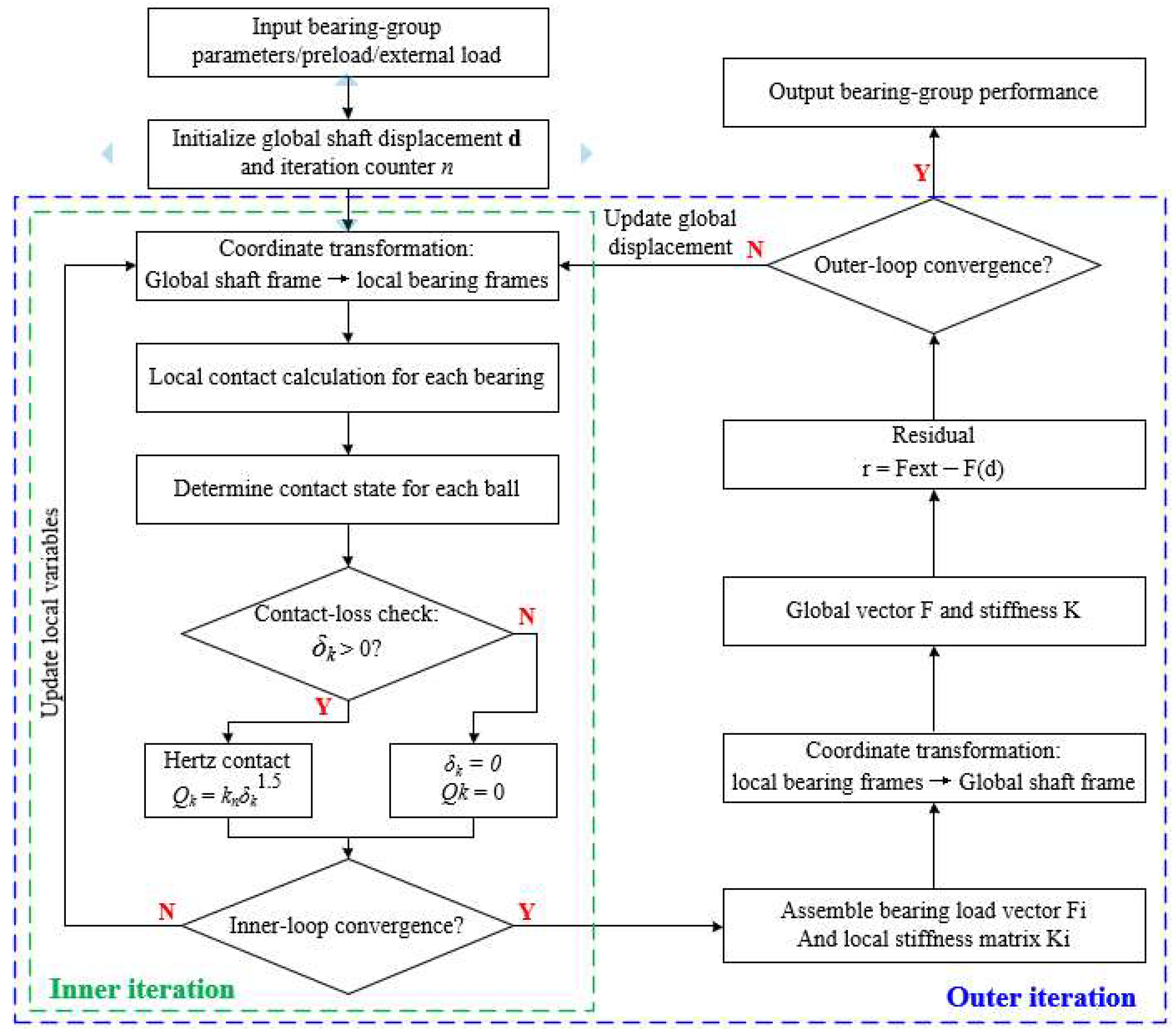
A nested iterative scheme is adopted, as shown in Figure 4. Single-bearing local contact calculation and global spindle equilibrium computation are coupled together.
Figure 4.
Iterative solution produce for bearing-group stiffness.
Local contact status of each bearing is solved in the inner iteration loop. Local displacement boundary is taken as input. Contact-loss logic is executed for every rolling element. Local convergence is achieved before bearing load vectors and stiffness matrices are returned. Shaft-center displacement is updated in the outer iteration loop. Force-moment residual at the spindle reference point is evaluated.
Coordinate transformation matrices are repeatedly used for quantity conversion between local bearing frames and the global shaft frame. Iteration cycles are repeated. The computation is terminated when the norm of residual falls below the preset convergence tolerance. Preload redistribution, spatial-position offset and nonlinear ball–raceway detachment are fully considered in this nested workflow.
4. Experimental Validation of Stiffness Model
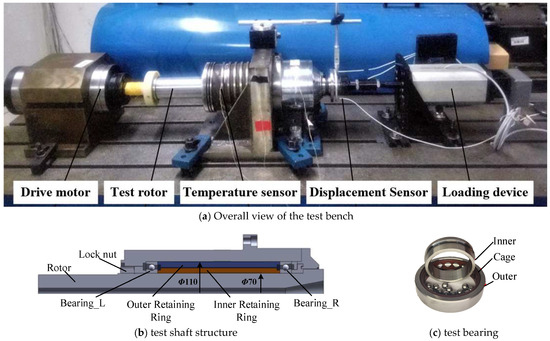
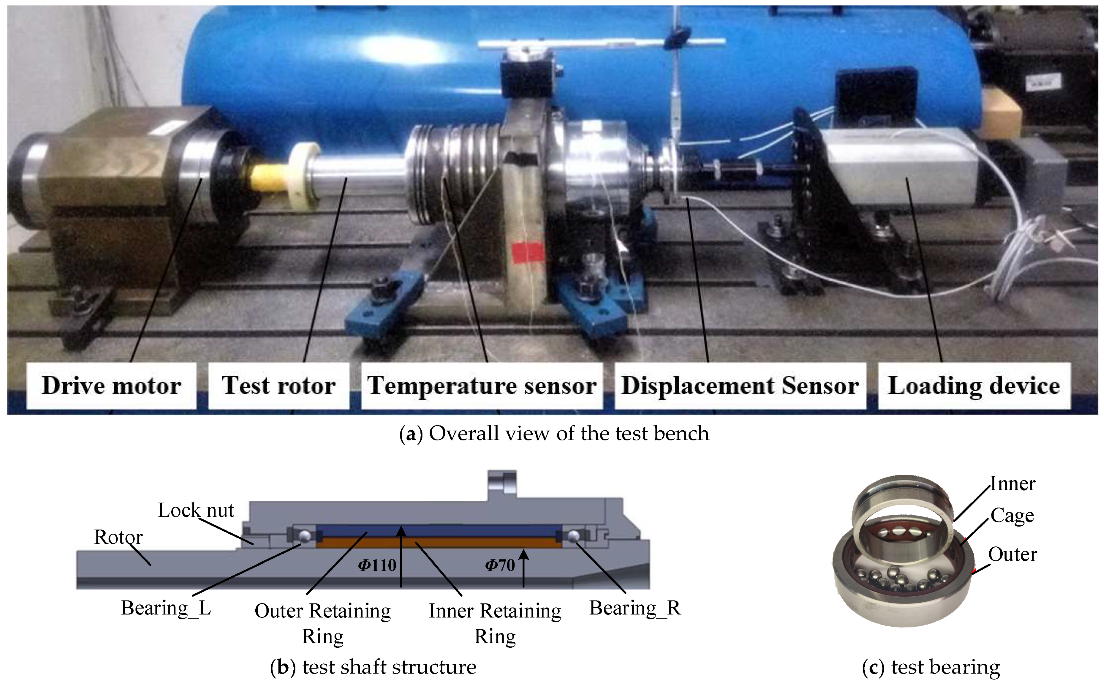
To verify the accuracy of the proposed stiffness model for the bearing group, experimental tests are carried out on a dedicated bearing-rig test-bench. The test-rig structure and the geometric parameters of the tested 7014C angular-contact ball bearing are shown in Figure 5, and its parameter is listed in Table 1. The test-bearing is assembled between two retaining rings, and preload is applied by tightening the lock nut. The preload is transmitted to the corresponding bearing inner and outer rings through the end faces of the inner and outer spacers. The external axial test load is applied at the spindle end and transmitted through the spindle and bearing contact interfaces to the bearing housing and supporting structure. During the experiment, the axial load is controlled, and the corresponding axial displacement of the spindle is measured to obtain the load–displacement relationship. Drive motor, loading device, displacement sensors and temperature sensors are equipped to enable load application, displacement acquisition and real-time condition monitoring.
Figure 5.
Photograph of the bearing-group stiffness test rig.
Table 1.
Geometric parameters of the tested bearing 7014C.
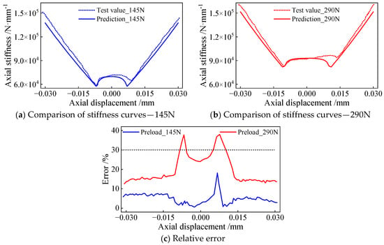
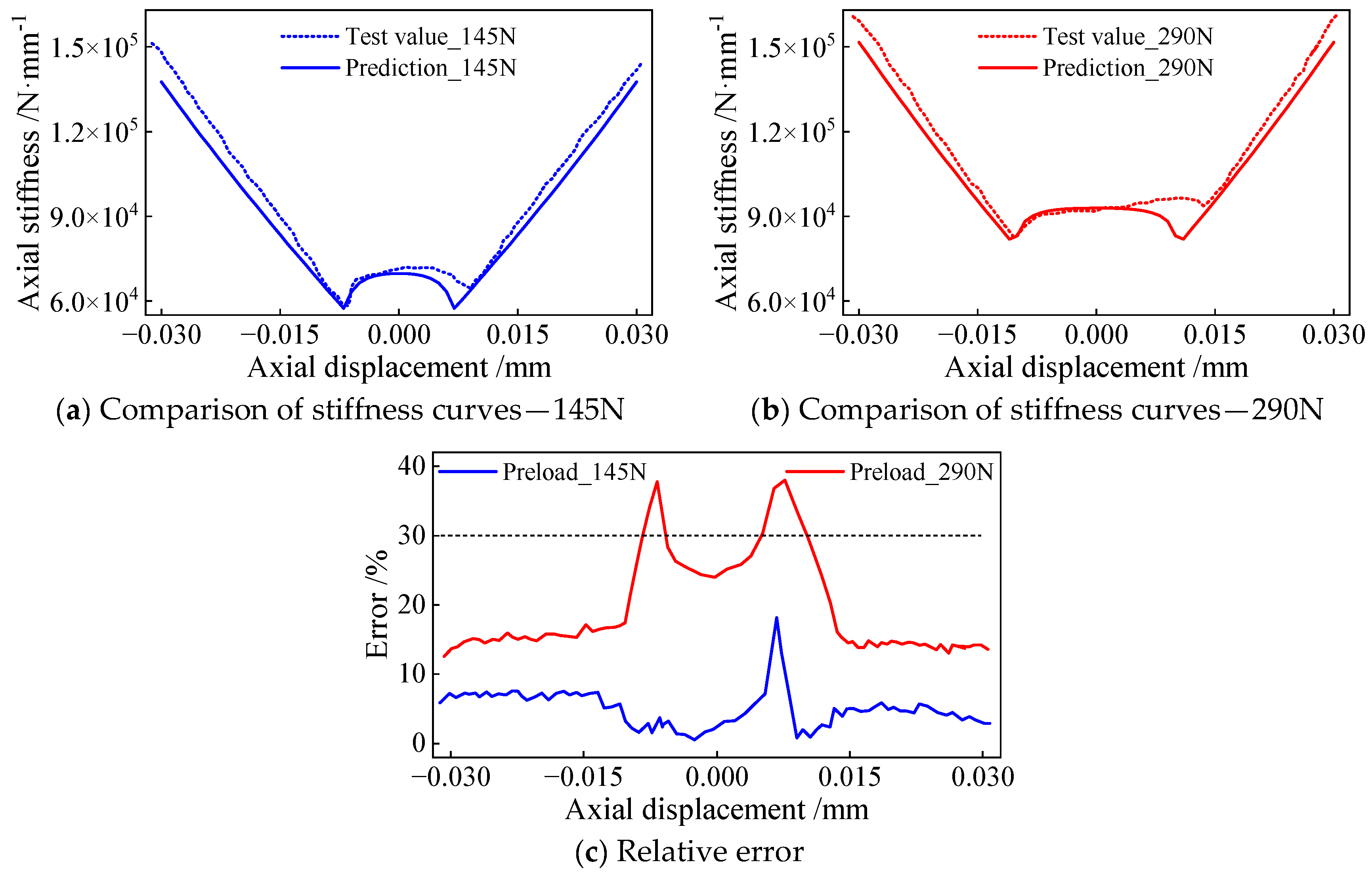
In this test, controlled axial loads are applied to the rotor, and the corresponding axial displacement responses are measured. The experimental stiffness is obtained by numerical differentiation of measured load–displacement data. Two preload levels of 145 N and 290 N are investigated. For each preload condition, axial load is gradually adjusted, and the force–displacement dataset is recorded. The stiffness–displacement curves calculated from experimental data are compared with the model-predicted results, as shown in Figure 6.
Figure 6.
Model validation of bearing-group stiffness.
The simulated curves show good overall agreement with the experimental results in Figure 6a,b. The nonlinear stiffness softening originating from ball–raceway contact loss can be well reproduced by the model. Relative error between simulation and test is plotted in Figure 6c. Under the preload of 145 N, the relative error remains small across most displacement ranges. For the higher preload of 290 N, obvious deviation appears near both ends of the displacement interval. Such discrepancy mainly comes from assembly stiffness and mounting errors under practical test conditions. The comparison proves that the proposed model can correctly simulate the nonlinear stiffness behaviours of ball bearings under different preload magnitudes.
5. Bearing-Group Stiffness and Contact Properties Under Different Configurations
Based on the present model, the mechanical behaviours of duplex-, triplex- and quadruplex-bearing assemblies are investigated. Two structural schemes are considered for each configuration: all bearings adopt the initial contact angle of 15°, or partial bearings are replaced by bearings with 25°. The variations of global stiffness (axial, radial, angular), contact angle and ball–raceway contact load under axial displacement excitation are analysed comparatively.
5.1. Duplex-Bearing Arrangement
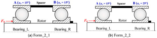
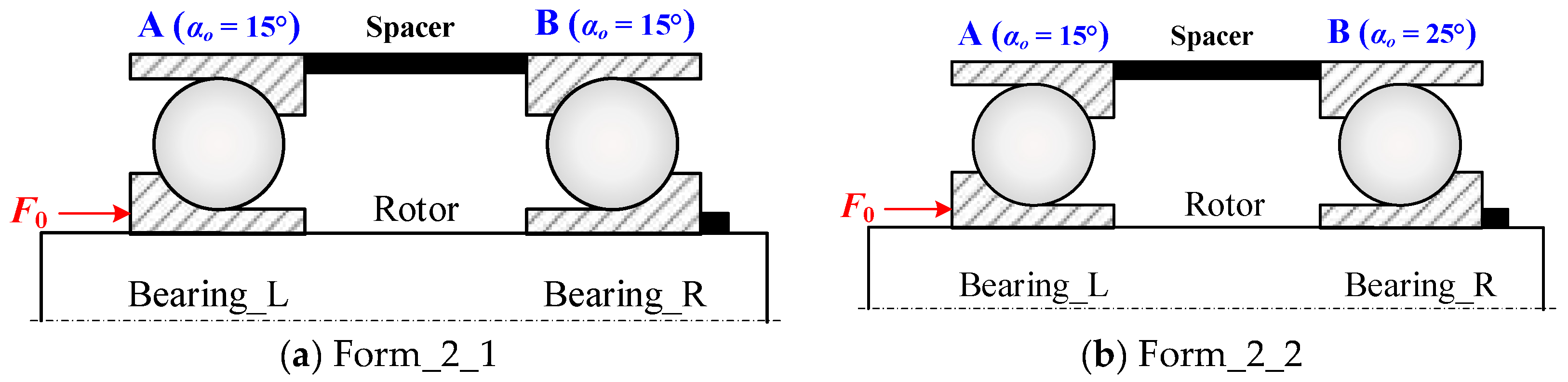
Two duplex-bearing layouts are displayed in Figure 7. Form_2_1 adopts bearings with identical 15° initial contact angle on both sides, while Form_2_2 equips the right-side bearing with a larger initial contact angle of 25°.
Figure 7.
Schematic diagrams of duplex-bearing group configurations.
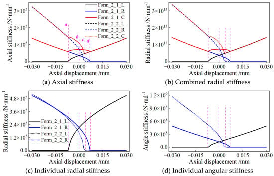
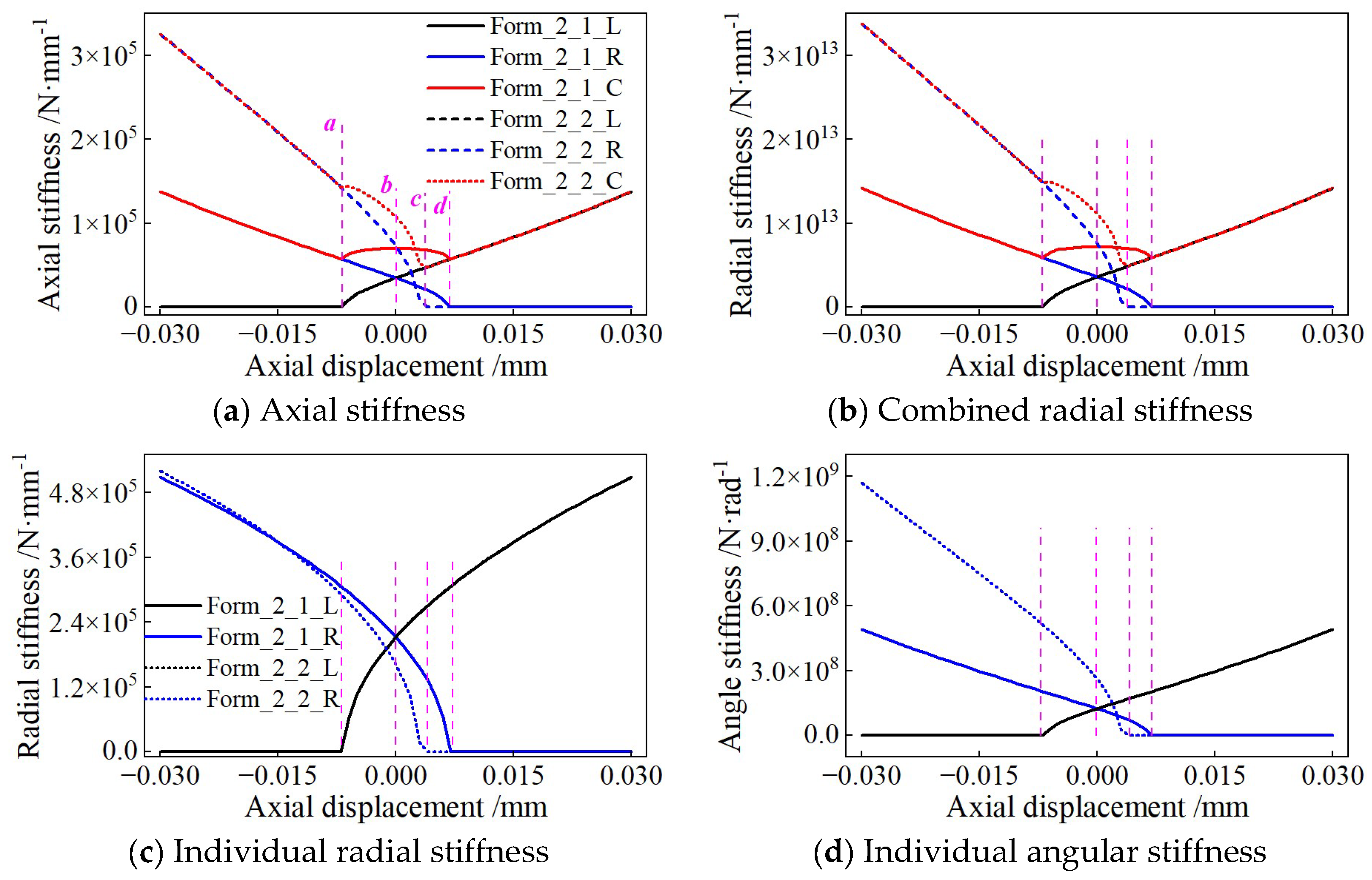
Figure 8 presents the stiffness characteristics of duplex-bearing groups. For Form_2_1 and Form_2_2, the overall axial and radial stiffness decrease gradually as axial displacement increases towards the negative direction. Sharp stiffness drop occurs once partial rolling elements lose contact. Form_2_2 yields higher axial stiffness and lower radial stiffness compared with Form_2_1. It indicates that increasing the initial contact angle of partial bearings improves the axial load-bearing capacity at the cost of radial stiffness deterioration. The stiffness curves of individual left- and right-side bearings further reveal the sequential contact-loss process of each bearing component. (If a certain color of the dashed line cannot be discerned, it indicates that the dashed line and the corresponding solid line of the same color have overlapped together.)
Figure 8.
Stiffness analysis of duplex-bearing group.
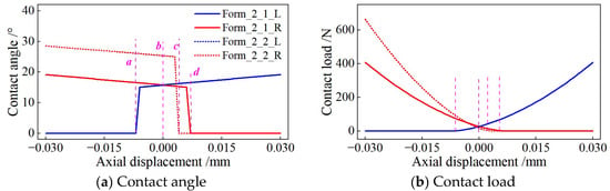
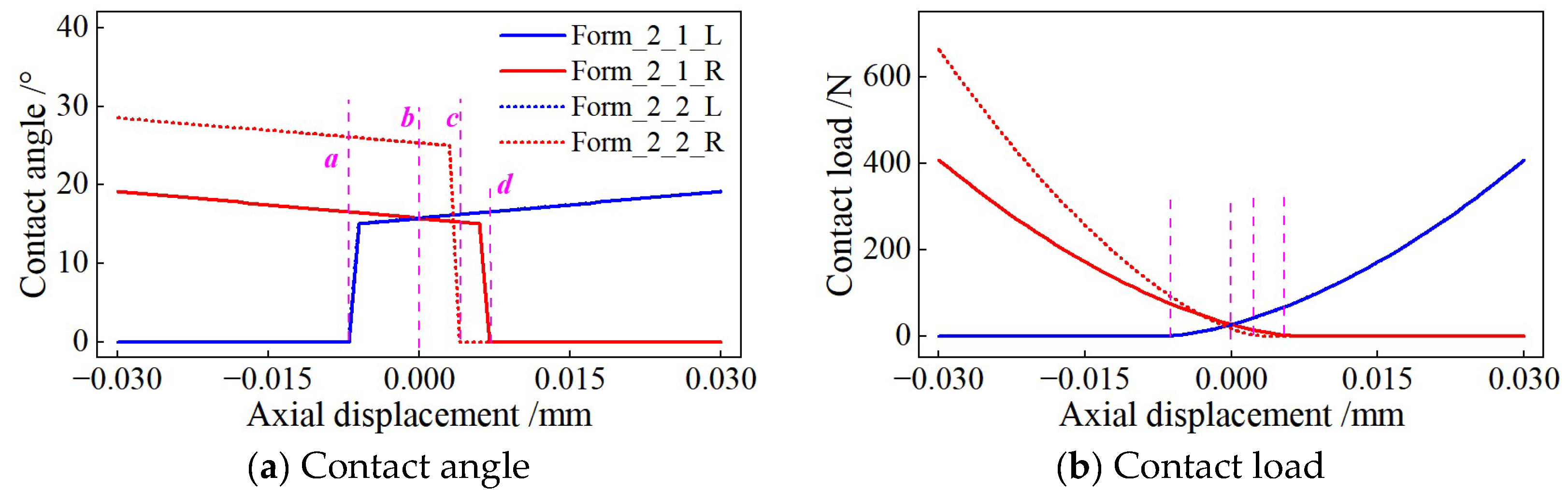
Contact characteristics are plotted in Figure 9. With the increase of negative axial displacement, the contact angle of the unloading-side bearing declines rapidly, accompanied by continuous drop of contact load. Once the contact load falls to zero, ball–raceway detachment takes place. The bearing with larger initial contact angle maintains contact under larger axial offset, which delays the occurrence of contact loss.
Figure 9.
Contact characteristics of duplex bearing.
5.2. Triplex Bearing Arrangement
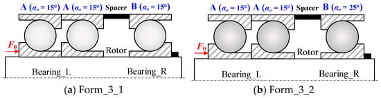
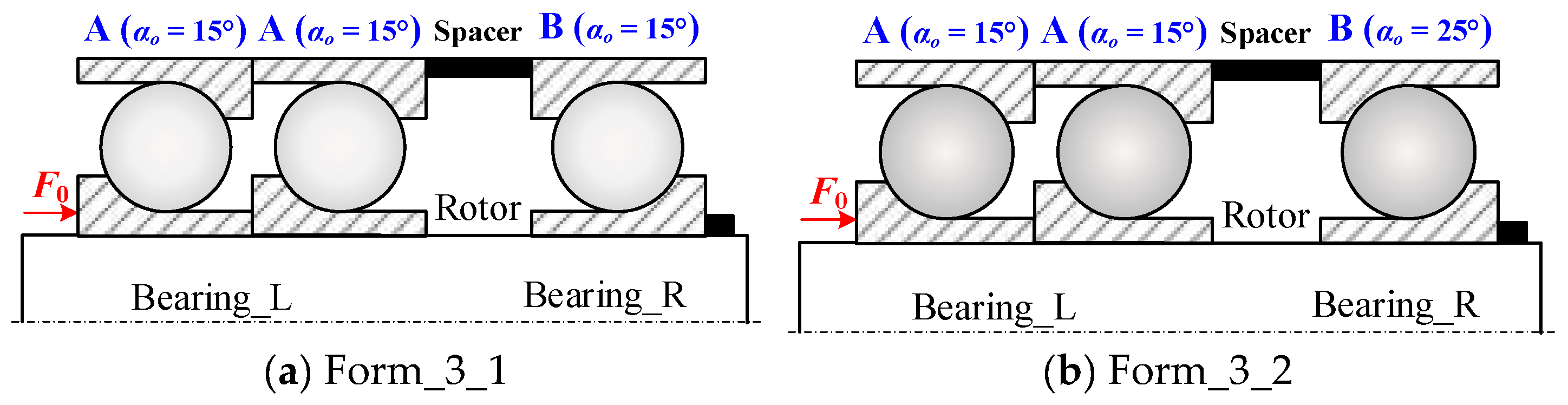
Figure 10 illustrates two triplex-bearing configurations. Form_3_1 uses three bearings with a 15° initial contact angle; Form_3_2 adopts a 25°-contact-angle bearing on the right-hand side.
Figure 10.
Schematic diagrams of triplex-bearing group configurations.
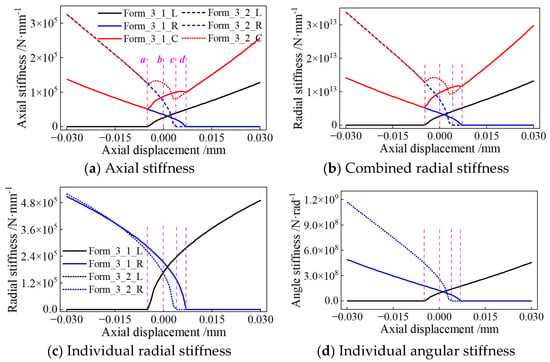
As shown in Figure 11, the triplex-bearing assembly obtains higher baseline stiffness than the duplex layout owing to the additional bearing component. The whole assembly still exhibits obvious nonlinear softening under axial displacement. Form_3_2 achieves superior axial stiffness, whereas its radial stiffness is weakened. Owing to the existence of the intermediate bearing, the contact-loss sequence becomes more complicated. The unloading-side bearing detaches first, followed by the intermediate bearing with further axial offset.
Figure 11.
Stiffness analysis of triplex-bearing group.
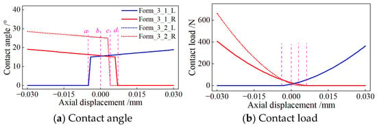
Figure 12 shows the evolution of internal contact angle and contact load for the triplex-bearing group. Multi-stage contact-loss behaviour can be observed. The introduction of a 25°-contact-angle bearing postpones the zero-load point of corresponding rolling contacts and expands the effective working displacement range of the bearing group.
Figure 12.
Contact characteristics of triplex-bearing group.
5.3. Quadruplex-Bearing Arrangement
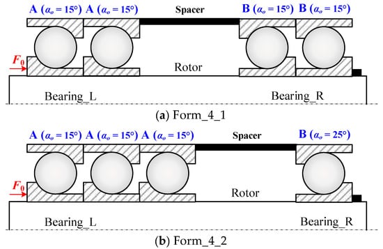
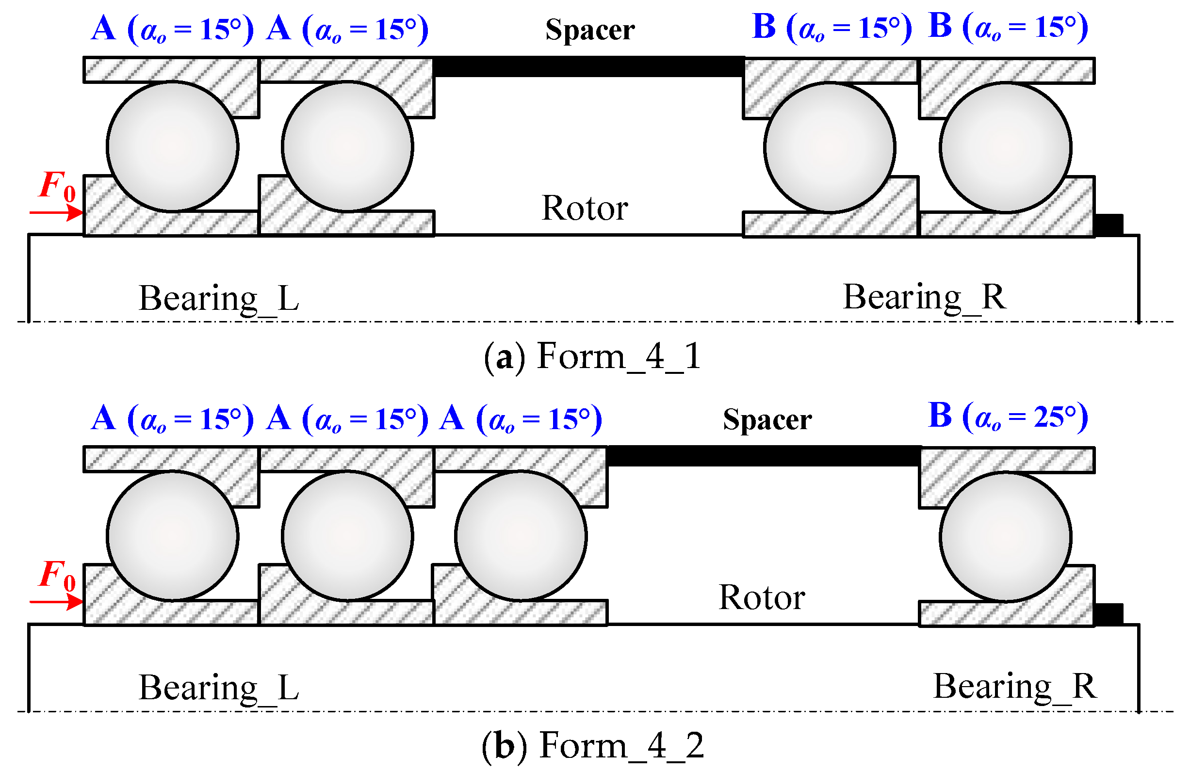
Quadruplex-bearing structural forms are given in Figure 13. Form_4_1 consists of four bearings with 15° initial contact angles. Form_4_2 employs a 25°-contact-angle bearing on the right side.
Figure 13.
Schematic diagrams of quadruplex-bearing group configurations.
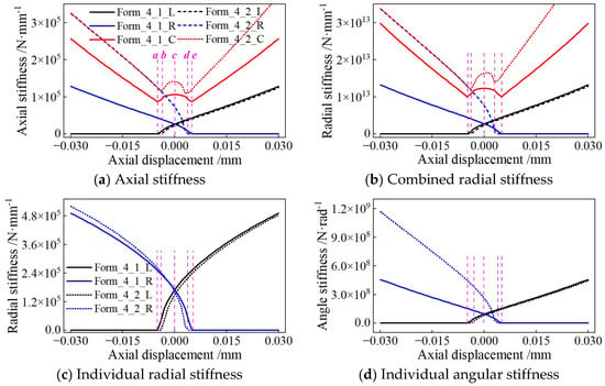
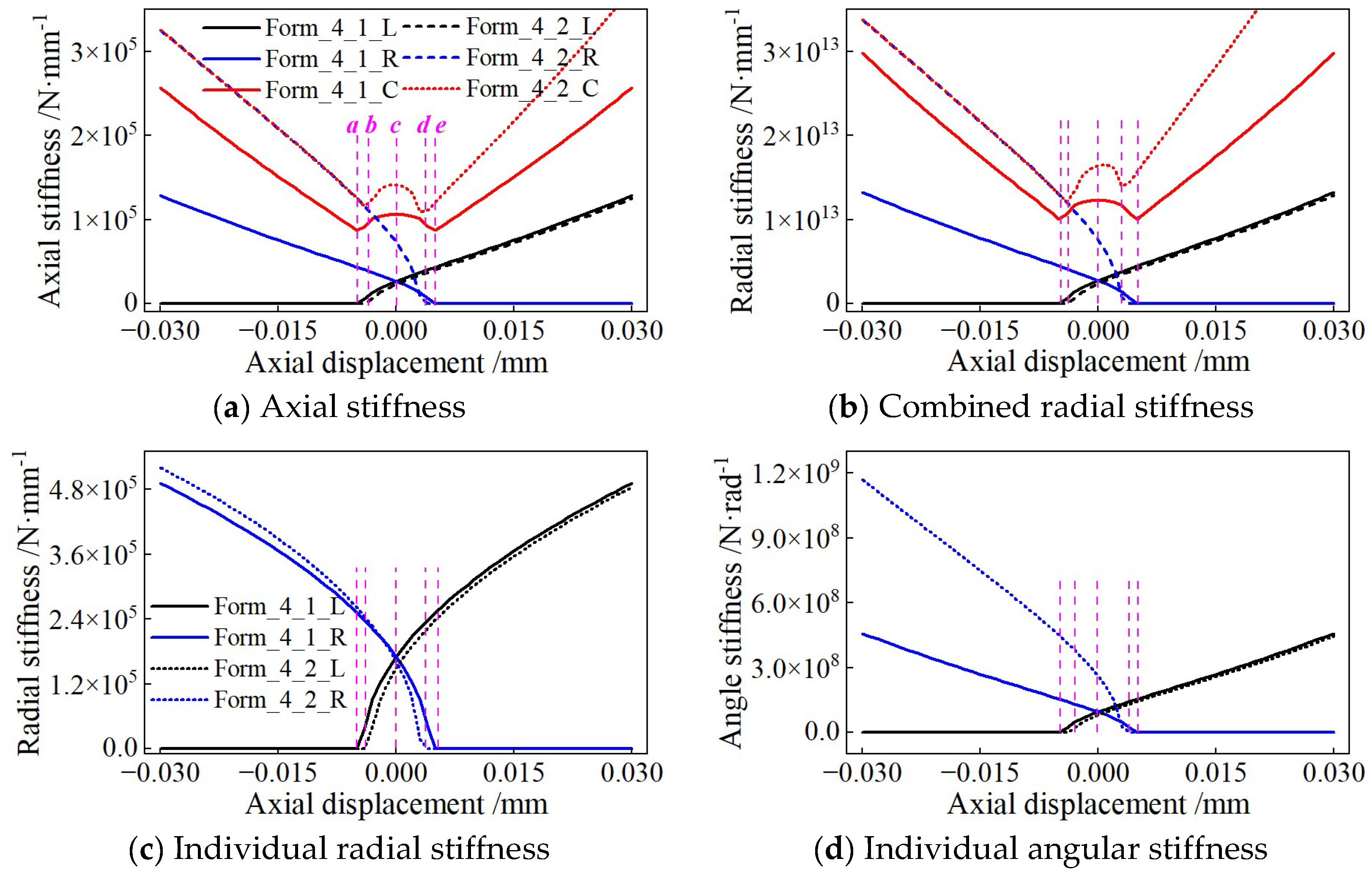
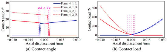
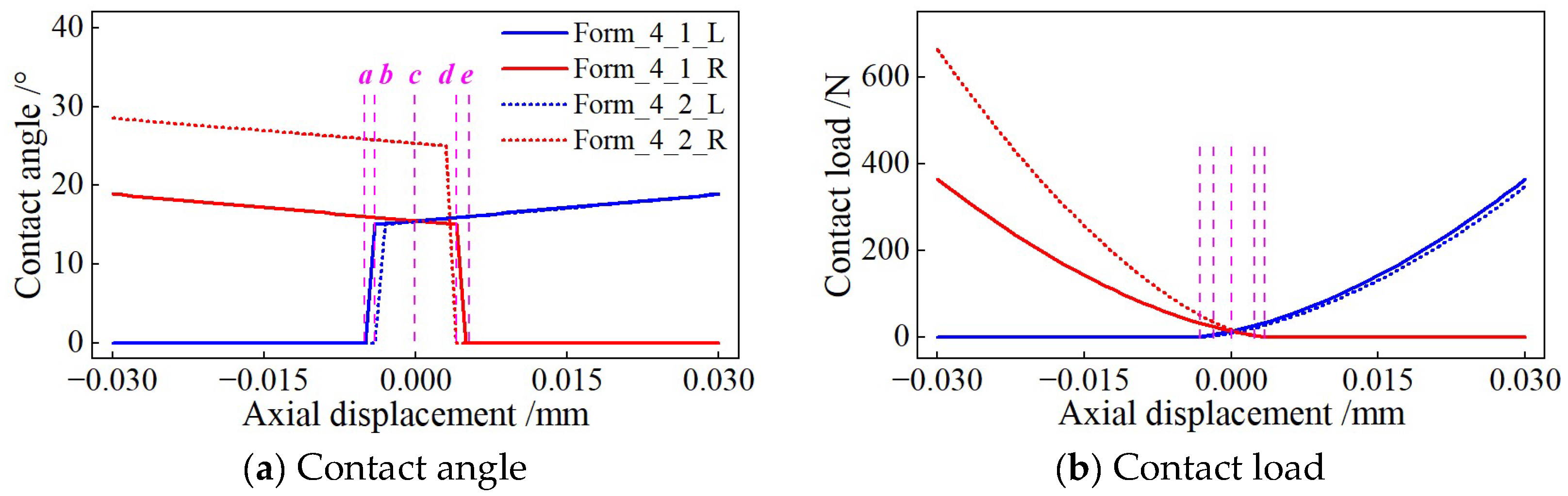
From Figure 14, the quadruplex-bearing group possesses the maximum initial axial, radial and angular stiffness among the three assembly forms. Nevertheless, nonlinear stiffness degradation and multi-stage contact loss still emerge under large axial displacement. Compared with Form_4_1, Form_4_2 enhances axial stiffness and enlarges the displacement interval before contact loss, at the expense of radial stiffness performance.
Figure 14.
Stiffness analysis of quadruplex-bearing group.
Figure 15 describes internal contact characteristics of quadruplex-bearing assembly. Multiple contact-load drop-off stages correspond to the successive detachment of different bearings. Adopting bearings with larger initial contact angles can effectively restrain the attenuation of contact angle and contact load on the unloading side.
Figure 15.
Contact characteristics of quadruplex-bearing group.
Comparative analysis demonstrates that increasing the number of bearings can promote the overall stiffness of the bearing group. Replacing partial bearings with a larger initial contact angle is an effective way to improve axial stiffness and anti-separation capability under axial offset, while it will reduce radial stiffness. For multi-bearing spindle systems, the trade-off between axial and radial performance should be considered in structural scheme selection.
6. Conclusions
This study presents a nonlinear stiffness formulation for multi-bearing assemblies that incorporates preload redistribution, coordinate transformations, and ball–raceway contact loss. These phenomena are captured through global-to-local displacement mapping and stiffness matrix assembly, while a nested iterative algorithm is developed to account for variations in rolling-element contact conditions. The proposed model is validated using tangent stiffness values derived from experimentally measured load–displacement curves. The principal findings obtained from the numerical simulations and experimental investigations are summarised as follows:
- Load sharing within multi-bearing assemblies is inherently non-uniform, and individual bearings undergo progressive unloading and successive contact loss as axial displacement increases. Although a greater number of bearings leads to higher baseline stiffness, it does not eliminate the uneven distribution of loads among the bearings.
- The arrangement of bearings plays a decisive role in determining the overall mechanical performance of the assembly. Increasing the initial contact angle enhances axial stiffness and resistance to bearing separation, but simultaneously reduces the assembly’s radial load-carrying capacity.
- When the number of bearings remains unchanged, variations in assembly configuration alter the axial displacement at which contact loss begins. Consequently, increasing the bearing count alone cannot extend the effective operating range indefinitely. Appropriate coordination between the assembly configuration and the initial contact angle is therefore essential to achieve balanced bearing-group performance.
Author Contributions
Writing—review and editing, Conceptualization, Methodology, and Project administration, B.W.; Validation, Formal analysis, and Data curation, Writing—original draft, J.L.; Investigation and Visualization, P.T.; Software, X.G.; Supervision, Q.X.; Providing financial support, and making revisions to the article, S.M. All authors have read and agreed to the published version of the manuscript.
Funding
This research was funded by the Fundamental Research Funds for the Central Universities, grant number xzy012025002.
Data Availability Statement
The data presented in this study are available within the article. Inquiries can be directed to the corresponding author.
Conflicts of Interest
Authors Jianfeng Li Pei Tian were employed by the company Shaanxi Fast Automotive Transmission Group Co., Ltd. The remaining authors declare that the research was conducted in the absence of any commercial or financial relationships that could be construed as a potential conflict of interest.
Appendix A
For a ball bearing with Z balls, the partial derivatives of bearing force-moment components with respect to local bearing displacements are given below.
Index k denotes the k-th ball, φk is its azimuth angle around the bearing axis, αk is the working contact angle, Ri is the pitch radius of the bearing, kn denotes the Hertz contact deflection, δk is deflection between ball and raceways, ri/o is the curvature radius of inner/outer raceway, Dw is the ball diameter.
Auxiliary coefficients Ak and Bk are defined as:
Partial-derivative expressions:
References
- Akturk, N.; Uneeb, M.; Gohar, R. The effects of number of balls and preload on vibrations associated with ball bearings. J. Tribol. 1997, 119, 747–753. [Google Scholar] [CrossRef] [Scilit]
- Li, H.; Shin, Y.C. Analysis of bearing configuration effects on high speed spindles using an integrated dynamic thermo-mechanical spindle model. Int. J. Mach. Tools Manuf. 2004, 44, 347–364. [Google Scholar] [CrossRef] [Scilit]
- Zhang, J.; Fang, B.; Hong, J.; Wan, S.; Zhu, Y. A general model for preload calculation and stiffness analysis for combined angular contact ball bearings. J. Sound Vib. 2017, 411, 435–449. [Google Scholar] [CrossRef] [Scilit]
- Zhang, Y.; Zhao, B.; Xie, Z.; Li, S.; Zhang, L. A novel method for solving bearing stiffness in rotor system supported by multiple bearings. Meccanica 2026, 61, 21. [Google Scholar] [CrossRef] [Scilit]
- Harris, T.A.; Kotzalas, M.N. Advanced Concepts of Bearing Technology: Rolling Bearing Analysis, 5th ed.; CRC Press: Boca Raton, FL, USA, 2006. [Google Scholar]
- Jones, A.B. A general theory for elastically constrained ball and radial roller bearings under arbitrary load and speed conditions. J. Basic Eng. 1960, 82, 309–320. [Google Scholar] [CrossRef] [Scilit]
- Lim, T.C.; Singh, R. Vibration transmission through rolling element bearings, part I: Bearing stiffness formulation. J. Sound Vib. 1990, 139, 179–199. [Google Scholar] [CrossRef] [Scilit]
- Lim, T.C.; Singh, R. Vibration transmission through rolling element bearings, part II: System studies. J. Sound Vib. 1990, 139, 201–225. [Google Scholar] [CrossRef] [Scilit]
- Lim, T.C.; Singh, R. Vibration transmission through rolling element bearings. Part III: Geared rotor system studies. J. Sound Vib. 1991, 151, 31–54. [Google Scholar] [CrossRef] [Scilit]
- Liew, H.V.; Lim, T.C. Analysis of time-varying rolling element bearing characteristics. J. Sound Vib. 2005, 283, 1163–1179. [Google Scholar] [CrossRef] [Scilit]
- Noel, D.; Ritou, M.; Furet, B.; Le Loch, S. Complete analytical expression of the stiffness matrix of angular contact ball bearings. J. Tribol. 2013, 135, 041101. [Google Scholar] [CrossRef] [Scilit]
- Liu, J.; Tang, C.; Wu, H.; Xu, Z.; Wang, L. An analytical calculation method of the load distribution and stiffness of an angular contact ball bearing. Mech. Mach. Theory 2019, 142, 103597. [Google Scholar] [CrossRef] [Scilit]
- Petersen, D.; Howard, C.; Prime, Z. Varying stiffness and load distributions in defective ball bearings: Analytical formulation and application to defect size estimation. J. Sound Vib. 2015, 337, 284–300. [Google Scholar] [CrossRef] [Scilit]
- Li, X.; Yu, K.; Ma, H.; Cao, L.; Luo, Z.; Li, H.; Che, L. Analysis of varying contact angles and load distributions in defective angular contact ball bearing. Eng. Fail. Anal. 2018, 91, 449–464. [Google Scholar] [CrossRef] [Scilit]
- Zhang, Y.; Fang, B.; Kong, L.; Li, Y. Effect of the ring misalignment on the service characteristics of ball bearing and rotor system. Mech. Mach. Theory 2020, 151, 103889. [Google Scholar] [CrossRef] [Scilit]
- Yun, X.; Han, Q.; Wen, B.; Hao, X. Dynamic stiffness and vibration analysis model of angular contact ball bearing considering vibration and friction state variation. J. Vibroengineering 2022, 24, 221–255. [Google Scholar] [CrossRef] [Scilit]
- Sheng, X.; Li, B.; Wu, Z.; Li, H. Calculation of ball bearing speed-varying stiffness. Mech. Mach. Theory 2014, 81, 166–180. [Google Scholar] [CrossRef] [Scilit]
- Yu, C.; Zhang, Q.; Gao, W.; Yu, H.; Xu, H. Research on rolling-bearing assembly method based on circumferential symmetry. J. Xi’an Univ. Technol. 2025, 45, 588–596. [Google Scholar]
- Bercea, I.; Nelias, D.; Cavallaro, G. A unified and simplified treatment of the non-linear equilibrium problem of double-row rolling bearings. Part 1: Rolling bearing model. Proc. Inst. Mech. Eng. Part J J. Eng. Tribol. 2003, 217, 205–212. [Google Scholar] [CrossRef] [Scilit]
- Nelias, D.; Bercea, I. A unified and simplified treatment of the non-linear equilibrium problem of double-row rolling bearings. Part 2: Application to taper rolling bearings supporting a flexible shaft. Proc. Inst. Mech. Eng. Part J J. Eng. Tribol. 2003, 217, 213–221. [Google Scholar] [CrossRef] [Scilit]
- Gunduz, A.; Singh, R. Stiffness matrix formulation for double row angular contact ball bearings: Analytical development and validation. J. Sound Vib. 2013, 332, 5898–5916. [Google Scholar] [CrossRef] [Scilit]
- Gunduz, A.; Dreyer, J.T.; Singh, R. Effect of bearing preloads on the modal characteristics of a shaft-bearing assembly: Experiments on double row angular contact ball bearings. Mech. Syst. Signal Process. 2012, 31, 176–195. [Google Scholar] [CrossRef] [Scilit]
- Gu, J.; Yang, J.; Zhang, S.; You, S.; Shi, X. Modeling and mechanical characteristics analysis of matched angular contact ball bearings under combined loads. Adv. Mech. Eng. 2022, 14, 16878132221132951. [Google Scholar] [CrossRef] [Scilit]
- Lin, S.; Jiang, S. Study of the stiffness matrix of preloaded duplex angular contact ball bearings. J. Tribol. 2019, 141, 032204. [Google Scholar] [CrossRef] [Scilit]
- Yang, Z.; Chen, H.; Yu, T. Effects of rolling bearing configuration on stiffness of machine tool spindle. Proc. Inst. Mech. Eng. Part C J. Mech. Eng. Sci. 2018, 232, 775–785. [Google Scholar] [CrossRef] [Scilit]
- Zhang, J.; Fang, B.; Zhu, Y.; Hong, J. A comparative study and stiffness analysis of angular contact ball bearings under different preload mechanisms. Mech. Mach. Theory 2017, 115, 1–17. [Google Scholar] [CrossRef] [Scilit]
- Sun, F.; Hu, Y.; Liu, X. Comparative analysis of load distribution and dynamic stiffness characteristics of back-to-back combined ball bearing. J. Southwest Jiaotong Univ. 2026, 61, 207–221. [Google Scholar]
- Zhang, Z.; Wang, D.; Li, L.; Li, D.Y.; Zhang, W. Analysis on stiffness and preload of matched ball bearings with unequal contact angles. Bearing 2018, 2, 10–13. [Google Scholar]

Disclaimer/Publisher’s Note: The statements, opinions and data contained in all publications are solely those of the individual author(s) and contributor(s) and not of MDPI and/or the editor(s). MDPI and/or the editor(s) disclaim responsibility for any injury to people or property resulting from any ideas, methods, instructions or products referred to in the content. |
© 2026 by the authors. Licensee MDPI, Basel, Switzerland. This article is an open access article distributed under the terms and conditions of the Creative Commons Attribution (CC BY) license.