


Abstract
Water lubrication offers a cleaner alternative to oil in marine journal bearings, but its low viscosity produces thinner lubricant films and increases the risk of friction and wear. Appropriately designed surface textures can improve hydrodynamic performance. In water-lubricated bearings, the steel journal retains machined features far longer than the softer polymer bearing surface, making journal-mounted textures attractive. Most Reynolds-based studies, however, consider textures fixed to the stationary bearing, whereas journal-mounted textures rotate and introduce an additional time-dependent effect. Moving-mesh and moving-multigrid methods have been used to capture this motion. This study isolates the texture-motion contribution as an explicit source term in a journal-fixed frame and solves the mass-conserving p–θ formulation on a fixed finite-difference grid. For a long bearing with a single axial channel, the predictions agreed with CFD results to within 2%, whereas omitting the texture-motion term reversed the phase of the load response over the revolution. For a cavitating finite-length bearing with chevron textures, the formulation reproduced published pressure results and captured a local pressure-reformation peak that is absent when texture motion is neglected. For the same case, the journal-fixed formulation reduced the CPU time by 53.6% relative to a classical global-frame formulation on a fixed grid. The verification uses conventional lubricant properties at low eccentricity and an illustrative water-lubricated case shows that the same chevron texture increases the peak pressure at but reduces it at .
1. Introduction
Water-lubricated journal bearings (WLJBs) are critical components in marine applications such as propeller-shaft systems and pumps, where water replaces oil as the lubricating fluid [1]. In recent years, the use of water-lubricated bearings has increased due to their environmentally friendly nature, as water eliminates the risk of oil leakage and the associated environmental pollution, while enabling simpler designs that reduce maintenance demands and overall operational costs [2]. Due to the low viscosity of water, WLJBs generally operate at higher eccentricity ratios under comparable loading conditions, resulting in thinner lubricant films. As a result, these bearings often operate in mixed or boundary lubrication regimes, particularly at low rotational speeds, leading to increased direct contact between the journal and bearing surfaces, higher friction, and accelerated wear [3].
Considerable research has focused on improving the load-carrying capacity and overall tribological performance of WLJBs [4]. These efforts include the selection of advanced materials with improved wear resistance [5], optimization of bearing geometry [6], and implementation of surface texturing techniques [7]. Among these, surface texturing has emerged as a particularly promising method for enhancing performance and mitigating wear in journal bearings [8].
Recently, Ohdar and Behera [9] reviewed advances in textured water-lubricated bearings. They concluded that well-designed textures can improve film formation and reduce friction and wear. However, these benefits depend strongly on texture geometry and operating conditions. Similarly, Pei [10] found that variations in texture spacing produce nonlinear changes in film thickness and friction, further confirming that texture performance depends strongly on operating conditions. Accordingly, in a subsequent study [11], Ohdar and Behera employed a hybrid genetic algorithm and artificial neural network (GA–ANN) approach for the prediction and optimization of herringbone-grooved WLJB performance.
Surface texturing involves the deliberate modification of the bearing surface at the microscale, typically through the introduction of regularly distributed patterns such as dimples, grooves, or other features [9]. Manufacturing methods range from traditional mechanical machining and chemical etching to more advanced processes such as laser surface texturing (LST), which provides superior precision and greater flexibility in pattern design [12].
Experimental research in this field indicates that surface textures on the bearing can act as micro reservoirs in the mixed-lubrication regime, thereby enhancing lubrication. Moreover, in the hydrodynamic regime, individual texture features can function as micro-hydrodynamic bearings that modify the pressure distribution within the lubricant film [13], potentially increasing load-carrying capacity and improving bearing dynamic stability [14]. In addition, bearings with textured surfaces may exhibit a lower friction coefficient relative to untextured bearings, thereby further improving tribological performance [15].
Among studies focusing specifically on texturing of the stationary bearing surface, Brizmer and Kligerman [16] examined both full LST (texturing over the entire bearing surface) and partial LST (localized texturing in selected regions), showing that full LST generally reduces load capacity, whereas optimized partial LST can improve both load capacity and attitude angle at low eccentricities (), with limited benefit at higher eccentricities. Tala-Ighil et al. [17] conducted a numerical investigation into various dimple distributions in journal bearings. Their study revealed that texturing yields only negligible performance improvements when applied in either the main converging or diverging zones of the bearing surface. However, when textures are positioned at the transition between these zones, specifically at the onset of the diverging region, where pressure decreases from its maximum toward the cavitation pressure, significant performance benefits can be achieved [17]. These results highlight the necessity for texture designs to be carefully tailored to the specific bearing geometry and prevailing operating conditions. Li et al. [18] explored the effects of texture bottom profiles on the static and dynamic characteristics of journal bearings. Their results showed that selecting appropriate texture parameters is important for improving the static and dynamic performance of hydrodynamic journal bearings. Manser et al. [19] demonstrated that a well-designed texture arrangement can significantly enhance the performance of hydrodynamic journal bearings, even at the high eccentricity ratios typical of WLJBs. These findings contrast with previous research, where performance enhancements were observed only at lower eccentricity ratios [15,17]. These conflicting findings show that the effect of texturing depends strongly on operating conditions, which makes an accurate and efficient predictive formulation a prerequisite for exploring the high-eccentricity regime typical of WLJBs.
In WLJBs, the rotating journal is usually made of steel, while the stationary bearing is made of polymer or composite materials. Consequently, textures applied to the bearing surface may gradually degrade as the polymer wears during operation. In contrast, textures applied to the steel journal are expected to be retained more effectively over time because wear of the steel surface is generally much smaller than that of the polymer bearing material. Journal texturing, however, introduces a time-periodic effect as the features sweep through the converging and diverging regions. The theoretical investigation of lubricated journal bearings with grooves on the journal began with Hirs [20], who applied narrow-groove theory and averaged the flow over many grooves, thereby eliminating the groove-passing fluctuations. Jang and Chang [21] subsequently used a coordinate-mapped, finite-volume Reynolds model with the Elrod mass-conserving cavitation method to study finite herringbone grooves, although their analysis was essentially quasi-steady. Jang and Yoon [22] explicitly considered rotating journal grooves by formulating the Reynolds equation in a journal-fixed coordinate system and coupling the calculated forces and torque to the nonlinear journal motion. They predicted lower frictional torque and power loss than those obtained with grooves on the stationary sleeve and also identified periodic groove-passing forces and journal whirl. Cupillard et al. [23] advanced the treatment of texture motion by resolving a discrete microgroove moving with the shaft using an unsteady deforming-grid CFD model. The groove reduced the revolution-averaged load capacity but transported colder lubricant into the hotter bearing regions. Anjos et al. [24] subsequently represented rotating chevron textures using a mass-conserving Reynolds formulation and a moving-multigrid algorithm. They identified a localized pumping mechanism that increased load capacity and reduced eccentricity, attitude angle and side leakage, although frictional torque increased. In addition, they optimized the chevron geometry for different rotational speeds.
Because the Reynolds equation is invariant to the choice of reference frame, solving it in the journal-fixed frame does not alter the physical solution but only changes how the texture motion enters the equation. Building on the journal-fixed framework of Jang and Yoon [22], whose governing equation is equivalent to the one used here, the present study expresses the texture-advection contribution as an explicit source term and incorporates it into a fixed-grid, mass-conserving algorithm satisfying the JFO conditions. This enables cavitating problems with rotating textures to be solved on a grid fixed to the journal, without moving meshes or re-interpolation of the texture geometry. It also allows the error of treating a journal texture as a stationary film-thickness variation to be quantified directly by omitting the term. The formulation is verified against independent CFD predictions and the moving-multigrid results of Anjos et al. [24] under controlled low-eccentricity conditions, while its systematic application to the high-eccentricity, water-lubricated regime and to texture optimization is left to future work.
The remainder of this paper is organized as follows. Section 2 presents the mathematical formulation, including the geometric descriptions, coordinate transformations, and Reynolds equations for textured bearings and textured journals. Section 3 describes the numerical framework, which combines a finite-difference discretization with a mass-conserving formulation satisfying the Jakobsson–Floberg–Olsson (JFO) conditions, together with the procedures used to calculate the pressure distribution and load-carrying capacity. Section 4 defines the two physical configurations used to assess the proposed formulation. Section 5 presents and discusses the results by comparing the conventional treatment of texture solely as a film-thickness variation with the proposed formulation that retains the texture-motion contribution. The first case is verified against CFD predictions, whereas the second is benchmarked against the moving-grid results of Anjos et al. [24]. Section 5 also applies the formulation to water-lubricated conditions and compares its computational cost with that of a global-frame formulation. Finally, Section 6 summarizes the principal conclusions, discusses the significance of the findings and outlines directions for future research. Appendix A, Appendix B, Appendix C, Appendix D and Appendix E present the derivations of the Reynolds source terms, the CFD model, the grid-independence study and the details of the computational-efficiency comparison.
2. Mathematical Formulation
2.1. Coordinate Systems and Film-Thickness Model
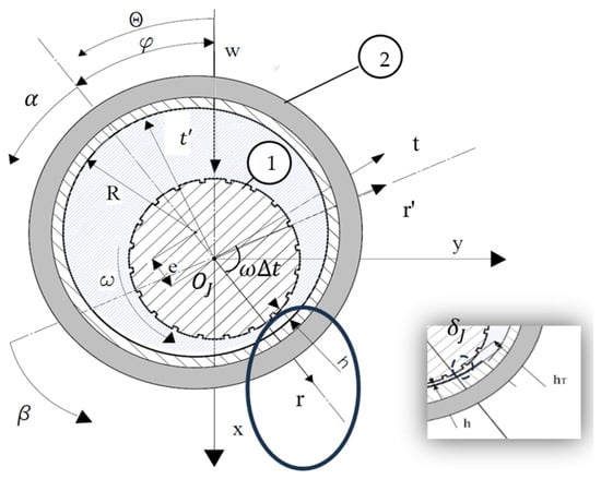
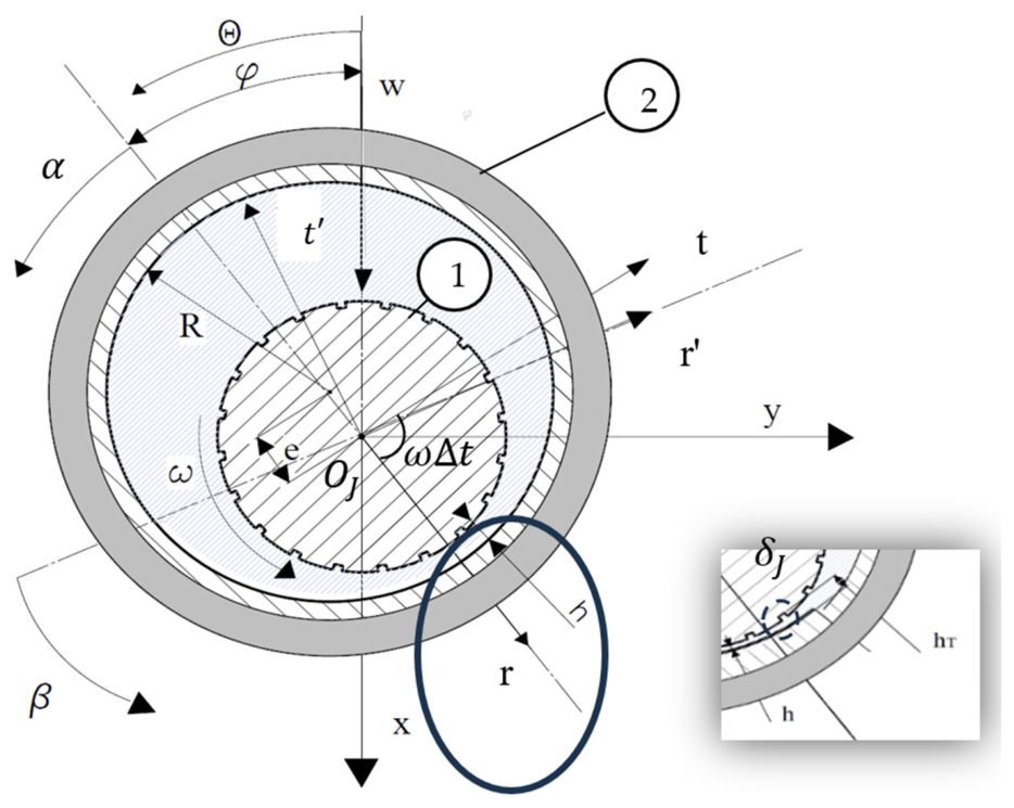
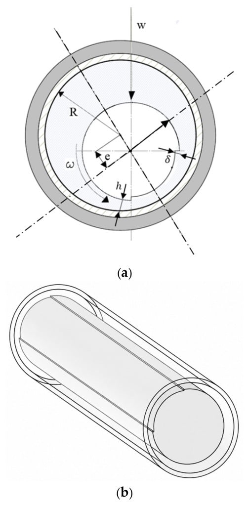
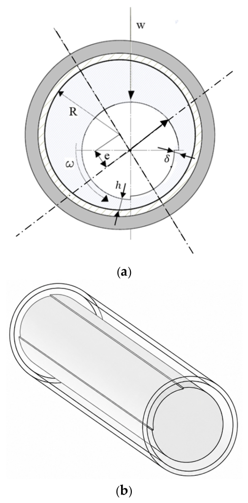
Figure 1 illustrates the bearing geometry and associated notation. The journal (1) rotates with angular velocity under an applied load inside a stationary bearing (2) of radius . The lubricant is characterized by its density and dynamic viscosity . The circumferential coordinate is measured from the load line. The circumferential coordinate is measured from the line of centers and the attitude angle is defined as the angle between the load line and the line of centers. Here, represents the nominal film thickness between the journal and the bearing and is assumed to be much smaller than the bearing length (L) and radius (R), i.e., and . The journal texture depth is denoted by , while represents the total film thickness defined as the sum of the nominal film thickness h and the texture depth . Here, the eccentricity magnitude is held constant, while the hydrodynamic force varies with journal rotation.
Figure 1.
Geometry and notation of a full-arc WLJB with a textured journal.
To facilitate the theoretical formulation for a textured journal, three coordinate systems are introduced, as shown in Figure 1:
- Global non-rotating frame .
- Rotated frame .
- Journal-fixed frame .
The global non-rotating frame has its axes fixed in direction along and across the load line, with origin at the journal center, whereas the journal-fixed frame is attached to the journal and rotates with angular velocity ω. The rotated frame is oriented at an attitude angle relative to the global non-rotating frame. The circumferential coordinate β is defined in the journal-fixed frame as: . The prime (′) notation denotes the parameters defined above when expressed in the journal-fixed coordinate system .
Figure 1 shows the relative positions of the three coordinate systems at a representative instant, after the journal has rotated through a nonzero angle . At , the journal-fixed frame is defined to be aligned with the rotated global frame . After the time increment , the journal-fixed frame is rotated relative to by an angular displacement , as shown schematically in Figure 1.
2.2. Reynolds Equation for Textured Surfaces
Surface textures affect the governing pressure equation differently depending on their location. The formulation distinguishes textures applied to the stationary bearing surface from those applied to the rotating journal’s surface and highlights the distinct physical mechanisms through which they influence hydrodynamic pressure generation. These formulations assume rigid surfaces, a Newtonian and isoviscous incompressible fluid, laminar flow, no-slip boundary conditions, isothermal conditions, negligible inertia and body forces, small surface slopes, and uniform pressure across the lubricant film thickness.
For a smooth journal and a textured bearing surface, the pressure distribution within the lubricant film is governed by the Reynolds equation, as commonly employed in the studies reviewed in Section 1 [15,16]:
When the bearing is textured and the journal is smooth, the total film thickness is given by:
where is the lubricant film pressure, is the axial coordinate, and is the circumferential surface speed of the journal. Here, denotes the nominal film thickness, while represents the bearing texture depth.
For a textured journal surface and a smooth bearing, as shown in Figure 1, the pressure is governed by a Reynolds formulation whose texture source term carries the opposite sign to that of the textured-bearing case in Equation (1):
where the total film thickness is given by:
Here, is the nominal film thickness and the journal texture depth. Substituting Equation (4) into the transient global-frame Reynolds equation and applying the chain rule yields Equation (3); the full derivation is provided in Appendix A.
For identical texture geometry, the key distinction between the two cases arises from texture motion. For a textured bearing, the stationary texture contributes to the source term with the same sign as the classical wedge term; for a textured journal, the moving texture contributes with the opposite sign.
Physically, consider a fixed point on the bearing surface as a journal texture feature passes it. When the feature arrives, the local film thickens and lubricant is drawn into the growing gap, lowering the pressure. When it leaves, the film thins and lubricant is squeezed out of the narrowing gap, raising the pressure. A journal texture therefore raises the pressure at its trailing edge. A texture of identical geometry on the stationary bearing does not change with time and acts as a step bearing, raising the pressure at its downstream edge, where the film narrows in the direction of the flow. Treating a journal texture as stationary therefore places the pressure rise at the wrong edge. For textures with inclined edges, such as chevrons, the pressure generated along each edge also varies axially and the resulting axial pressure gradients pump the lubricant toward or away from the bearing centerline, depending on the orientation of the chevrons relative to the direction of rotation [24]. Because the texture edges sweep through regions of different nominal film thickness, these effects alter the phase of the periodic load variation, as shown for Case 1 in Section 5.1. Within the cavitated region, the squeeze action, assisted for chevrons by the axial pumping, can also raise the pressure above the cavitation pressure and reform the film locally, as shown for Case 2 in Section 5.2.
Computing the pressure distribution and bearing performance for the textured-journal case directly from Equation (3) in the global frame is numerically challenging. In this frame the texture contribution depends on both position and time, whereas the nominal film thickness depends only on position, as shown by the decomposition in Equation (4). Consequently, the film-thickness profile must be updated at each time step to account for the evolving texture geometry. For realistic textures with hundreds or thousands of individual features, tracking the moving texture requires repeated interpolation onto the fixed global grid, increasing computational cost and potentially introducing interpolation errors that reduce geometric accuracy [24]. To overcome this difficulty, the Reynolds equation is solved in the journal-fixed frame [22]. The resulting formulation, in which the texture-advection contribution is expressed explicitly, is:
with the film thickness given by:
Here, denotes the nominal film thickness in the rotating frame, while represents the journal texture in the same frame. The derivation in the journal-fixed rotating frame is provided in Appendix B.
Equation (5) expresses the texture-advection contribution, which is otherwise embedded in the transient term of the global-frame formulation, as an explicit source on a fixed grid. This makes the contribution straightforward to implement, to isolate by omission, and to quantify, as demonstrated in the two verification cases.
The extension of Equation (5) to cavitating conditions, through the mass-conserving p–θ formulation, is presented in Section 3.
3. Numerical Implementation
The pressure distribution is calculated over the computational domain using the finite-difference method (FDM). In the cavitating case, the Jakobsson–Floberg–Olsson (JFO) boundary condition is implemented through the p–θ algorithm to conserve mass across the film-rupture and reformation boundaries.
3.1. Numerical Formulation
In journal bearings, cavitation occurs when the local pressure falls below the cavitation pressure, resulting in film rupture and the formation of cavitated regions [2]. To solve the Reynolds equation under cavitating conditions, appropriate cavitation boundary conditions must be imposed. The classical Swift–Stieber boundary condition accounts for film rupture but does not ensure mass conservation at the film-reformation boundary [25]. To address this limitation, the Jakobsson–Floberg–Olsson (JFO) boundary condition is adopted; its advantages over the Swift–Stieber condition in steadily loaded journal bearings have been documented [26]. The JFO condition is commonly implemented through the p– algorithm [27]. Mass conservation is enforced by a fluid fraction equal to unity in the full-film region and less than unity in cavitated zones. Incorporating the fluid fraction into Equation (5) gives the transient Reynolds formulation in the journal-fixed coordinate system [22]:
where:
Here, denotes the lubricant film pressure in the journal-fixed frame and is the cavitation pressure. Expanding the transient term and substituting the film-thickness time derivative gives the explicit form:
The derivation for Equation (8) in the journal-fixed rotating frame is provided in Appendix B. When cavitation is absent and , Equation (8) reduces to Equation (5).
Equation (8) is discretized on an m × n grid, where and are the numbers of circumferential and axial nodes. The resulting system of algebraic equations is solved iteratively by successive over-relaxation (SOR) to obtain the pressure field over the computational domain.
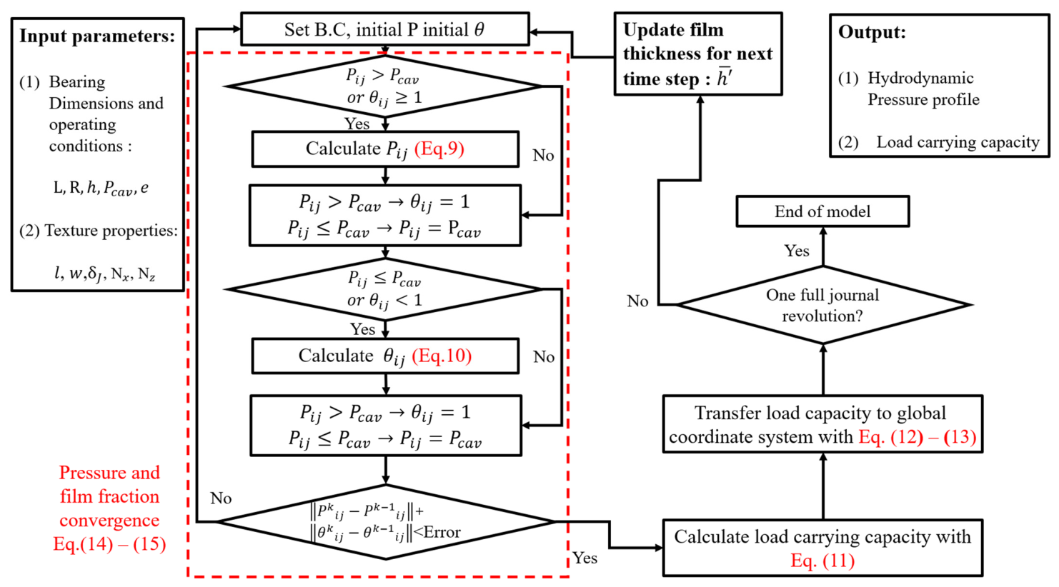
Solving the Reynolds formulation in the journal-fixed (r′, t′) frame yields the pressure and fluid-fraction fields at each time step. At every node the complementarity condition of Equation (7) determines which variable is updated, the pressure from Equation (9) in the full-film region and the fluid fraction from Equation (10) in the cavitated region. The discretized equations are:
Here, and denote the circumferential and axial coordinates, respectively. The indices identify the discrete grid points, and the corresponding spatial steps, the time-step and the superscript is the time-step index. Subscripts and refer to face-centered quantities used in the finite-difference formulation.
3.2. Computational Approach
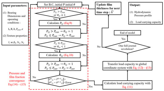
The iterative solution procedure, illustrated schematically in Figure 2, computes the pressure and fluid fraction fields in both the full-film and cavitated regions. The p– formulation enforces mass conservation across the rupture and reformation boundaries and captures the coupled behavior of the lubricating film under cavitating conditions. Iterations continue until the maximum residuals in both fields fall below a prescribed tolerance, indicating that a converged solution has been reached for that time step. The calculation then proceeds to the next time step, during which the journal rotates by , producing a corresponding change in the nominal film thickness. The time step was selected so that the journal rotates by no more than one circumferential cell per step, , ensuring that the relative motion between the texture and the nominal film-thickness profile is resolved at every grid cell. The process is repeated until the textured journal has completed one full revolution.
Figure 2.
Computational flowchart for solving the cavitating Reynolds formulation for a textured rotating journal.
To calculate the load-carrying capacity, the pressure distribution is integrated over the computational domain to obtain the hydrodynamic force components in the journal-fixed frame :
In the present formulation, the pressure field is obtained in the journal-fixed frame, so the hydrodynamic force components are first calculated in the local radial and tangential directions and then transformed, in two steps, into the global non-rotating frame, in which the external load and journal equilibrium are defined.
The first step maps the load vector from the journal-fixed frame to the rotated frame , using the rotation matrix evaluated at time t:
The second step maps the result from the rotated frame to the global non-rotating frame through the attitude angle .
After both transformations, the predicted hydrodynamic load vector is expressed in the global non-rotating frame, allowing the bearing response to be evaluated over a complete cycle, during which the pressure field and the resulting load vary periodically.
Since the eccentricity is prescribed, the load-carrying capacity reported in this study is the magnitude of the hydrodynamic force generated at that eccentricity, which is unchanged by the rotations of Equations (12) and (13). It is not an equilibrium load capacity, which would require solving the equations of motion of the journal for a given external load. The periodic effect of the rotating texture therefore appears as a variation in the hydrodynamic force over the revolution rather than as an oscillation of the journal about its equilibrium position.
The discretized system defined by Equations (9) and (10) together with the load calculation defined by Equations (11)–(13) constitutes the complete numerical framework for the textured journal.
3.3. Convergence Criteria and Numerical Parameters
At each time step k, the pressure and fluid-fraction fields were updated iteratively by SOR. The solution at that time step was accepted only when the normalized changes between successive iterations and q satisfied both of the following criteria:
where m and n are the numbers of circumferential and axial nodes, respectively. The maximum with unity in each denominator prevents division by zero, so that the criterion measures a relative change when the field norm exceeds one and an absolute change otherwise. Grids of 180 × 80 nodes for Case 1 and 257 × 65 nodes for Case 2 were selected on the basis of the grid-independence study presented in Appendix D. All numerical parameters used in the calculations are summarized in Table A2.
4. Verification Cases
This section presents the two configurations used to verify the proposed formulation in Equation (8). The first is an idealized long-bearing configuration at low eccentricity, in which the texture-induced effects are isolated by minimizing the conventional hydrodynamic wedge and axial end effects; it is verified against independent CFD simulations as described in Appendix C. The second is a finite-length bearing with a chevron texture pattern and cavitation, which introduces axial flow variation; it is benchmarked against the moving-multigrid results reported by Anjos et al. [24]. Together, the two cases verify the formulation under a simplified configuration and under a more complex one involving finite length, axial flow, and cavitation. Both cases are numerical verifications against independent solutions, and experimental validation of the formulation is left to future work.
4.1. Case 1: Long Bearing with a Single Axial Channel
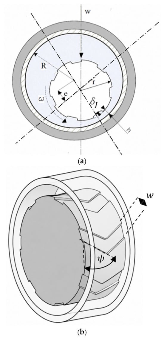
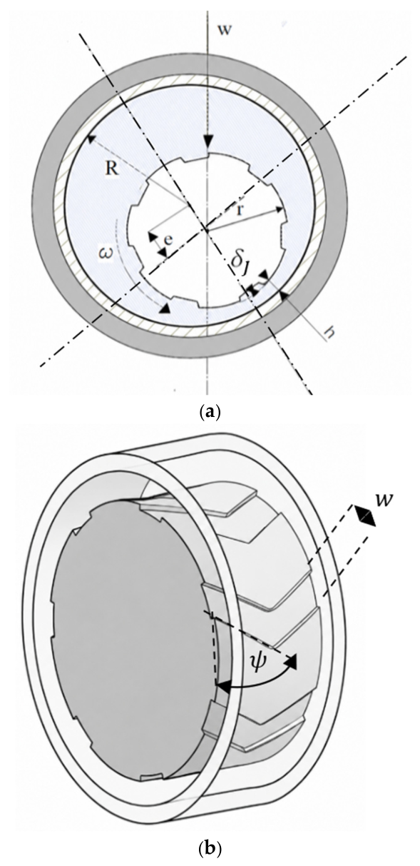
Figure 3 illustrates a journal bearing with a large length-to-diameter ratio (L/D = 10, where is the bearing diameter), which minimizes axial end effects and supports the long-bearing approximation. The journal rotates with angular velocity under an applied load within a bearing of radius . The radial clearance is the difference between the bearing radius and the journal radius . The journal surface texture consists of a single channel extending along the full axial length and occupying one-quarter of its circumference, with depth , while denotes the nominal film thickness between the journal and the bearing. A low eccentricity ratio was selected to emphasize the contribution of the surface texture and minimize the effect of the conventional hydrodynamic wedge mechanism. Cavitation was not imposed in this case, so that the Reynolds and CFD solutions could be compared under identical governing assumptions. The boundary conditions comprise periodic conditions in the circumferential direction and ambient pressure at the open axial ends.
Figure 3.
Case 1: (a) cross-sectional geometry and notation of the bearing shown in (b); (b) 3D view of the long bearing with a single axial channel on the rotating journal. Dimensions are not to scale; the radial clearance and channel depth are enlarged for clarity.
4.2. Case 2: Finite-Length Bearing with Chevron Texture
To assess the formulation under finite-length and cavitating conditions, a test case comprising seven chevron features (Figure 4) was examined. The bearing parameters follow the notation of Case 1. A low eccentricity ratio was selected to emphasize the contribution of the surface texture and reduce the effect of the hydrodynamic wedge mechanism, and it corresponds to the equilibrium value reported by Anjos et al. [24] for the load considered there. Unlike Case 1, this case employs a finite-length bearing (L/D = 0.5) and includes cavitation, thereby introducing axial flow and film rupture and reformation.
Figure 4.
Case 2: (a) geometry and notation for a finite-length bearing with a rotating chevron texture; (b) geometry and parameters of the chevron texture shown in (a). Dimensions are not to scale; the radial clearance and chevron depth are enlarged for clarity.
The texture pattern consists of a single row of chevrons positioned at the center of the journal surface and is characterized by four parameters: the number of chevrons around the journal circumference (), the chevron width , the chevron angle , and the uniform chevron depth (). The boundary conditions comprise a supply groove in the circumferential direction and ambient pressure at the open axial ends, consistent with the configuration of Anjos et al. [24].
5. Results and Discussion
This section presents results for the two textured-journal cases introduced in Section 4. For Case 1, predictions from the proposed formulation are compared with the CFD results obtained using the method described in Appendix C. To emphasize the texture contribution, the results are also compared with those obtained when the stationary-texture formulation in Equation (1) is applied while omitting the texture-motion term. For Case 2, the results are compared with those reported by Anjos et al. [24]. Section 5.3 then applies the formulation to the Case 2 configuration under water-lubricated conditions and Section 5.4 compares its computational cost with that of a global-frame formulation.
Although water-lubricated bearings motivate this work, the verification uses conventional higher-viscosity lubricant properties rather than water properties. In Case 2, these properties match those used by Anjos et al. [24], so the comparison is made under equivalent fluid properties. In addition, the low eccentricity reduces the hydrodynamic wedge contribution, so that the texture-motion contribution can be clearly observed.
5.1. Case 1 Results
Table 1 summarizes the main bearing parameters used in Case 1. The geometric characteristics of the texture features are presented in Table 2, where is the number of texture features around the journal circumference and, here, for the single channel, is the channel width, and is the channel depth. The single axial-channel geometry was selected to clearly isolate the influence of the additional texture-motion term in the Reynolds equation.
Table 1.
Bearing geometry and operating parameters–Case.1.
Table 2.
Surface texture properties-Case 1.
Cavitation was not imposed in this case. Although pressures below the cavitation pressure are not physically sustainable when cavitation occurs, they were retained so that the Reynolds and CFD solutions could be compared under identical governing assumptions.
The proposed formulation, Equation (8), was compared with the finite-volume CFD model described in Appendix C. The CFD simulations were performed using ANSYS Fluent (2021 R1) following a methodology similar to that of Cohen and Goltsberg [28]. The Reynolds model retains the finite bearing length and imposes ambient pressure at both axial ends, whereas the two-dimensional CFD model represents an axially uniform circumferential section. At with a channel extending along its full length, the axial pressure gradient is negligible over most of the bearing, so the two models may be compared on the normalized load. To isolate the texture-motion contribution, both are also compared with the textured-bearing Reynolds equation, Equation (1), which omits that contribution.
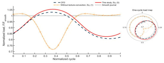
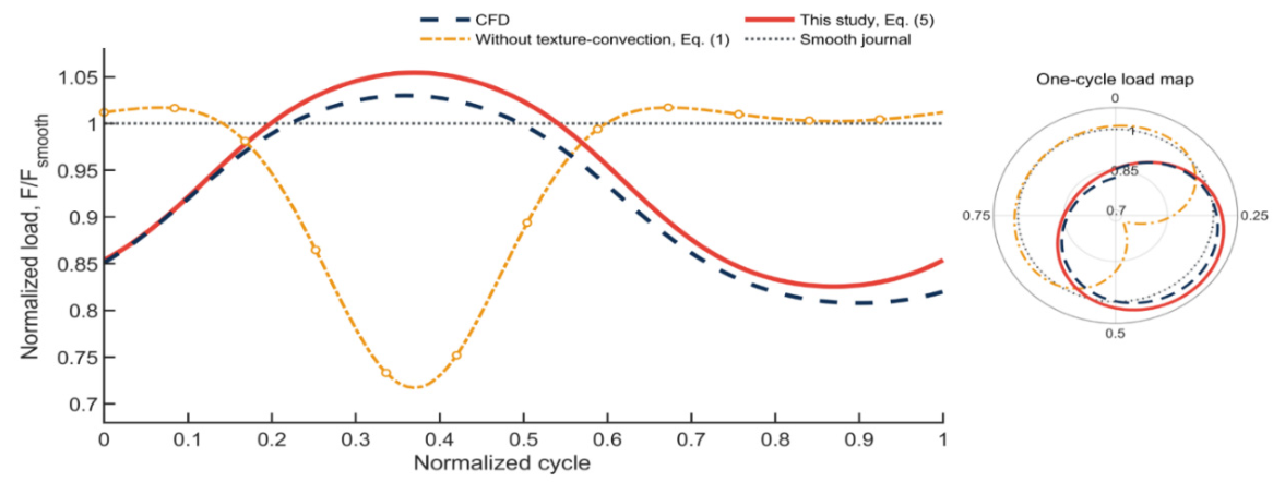
Figure 5 compares the normalized load-carrying capacity predicted by the proposed formulation, Equation (8), by the CFD model, and by the textured-bearing Reynolds equation, Equation (1), which omits the texture-motion term. The load is obtained from the pressure field as described in Section 3.2 and normalized by the corresponding value for the smooth journal. The comparison in Figure 5 is presented over one complete journal revolution, where a cycle fraction of 0 indicates that the and frames are aligned and a cycle fraction of 1 that the journal has completed one full revolution.
Figure 5.
Normalized load-carrying capacity over one journal revolution, predicted by the proposed and classical formulations and by CFD.
As expected, the normalized load-carrying capacity for the smooth journal remains constant throughout a complete revolution. In contrast, all three predictions for the textured journal vary periodically, since the textured region passes through the converging and diverging portions of the film, where the nominal film thickness differs, producing periodic variations in pressure generation and hence in the hydrodynamic load.
Figure 5 reveals a marked difference between the proposed formulation and the textured-bearing Reynolds equation, Equation (1), which omits the texture-motion term. The latter is phase-inverted relative to both the CFD result and the proposed formulation, predicting a maximum where the other two predict a minimum, and vice versa. The proposed formulation follows the CFD result closely, with a maximum discrepancy of 2% in normalized load-carrying capacity over the complete cycle, supporting the numerical implementation.
5.2. Case 2 Results
Table 3 summarizes the key bearing parameters used in this case. The geometric characteristics of the chevron textures are listed in Table 4, where denotes the number of chevrons around the journal circumference, the chevron width, the chevron angle, and the chevron depth. The chevron configuration was selected to evaluate the proposed formulation under a more complex, 3D texture geometry with cavitation.
Table 3.
Bearing geometry and operating parameters-Case 2.
Table 4.
Surface texture properties.
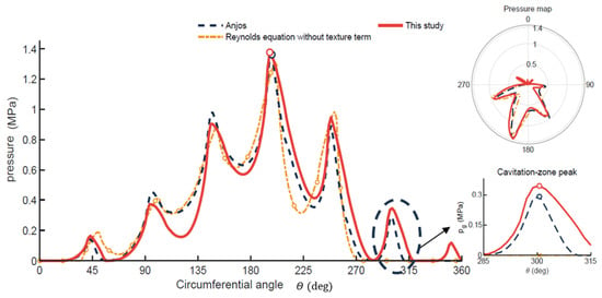
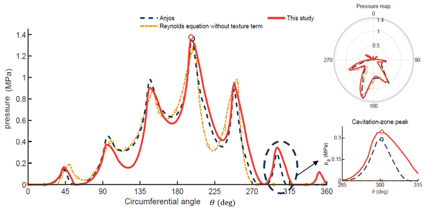
Figure 6 presents the circumferential pressure profiles predicted by the proposed formulation, Equation (8), by the textured-bearing Reynolds equation, Equation (1), which omits the texture-motion term, and by Anjos et al. [24]. Over the complete circumference, the proposed formulation reproduces the pressure distribution of Anjos et al. with a peak-normalized RMSE of approximately 4% and predicts the principal peak magnitude to within 1%. The peak-normalized RMSE is defined as:
where and are the predicted and the reference pressure at comparison point i, is the number of comparison points and is the maximum reference pressure of Anjos et al. [24].
Figure 6.
Case 2 : circumferential pressure distribution predicted by the proposed formulation, Equation (8), by the textured-bearing Reynolds equation, Equation (1), which omits the texture-motion term, and by Anjos et al. [24]. Insets show the polar pressure map and the pressure-reformation peak in the cavitated region.
The formulation without the journal-texture-motion contribution gives reasonable agreement in the converging region, where pressure is generated primarily by the mechanical wedge. Its peak-normalized RMSE is approximately 6%, and it predicts the principal peak magnitude within 5%.
The importance of the texture-motion contribution becomes evident in the diverging, cavitation-dominated region shown in the inset. Both Anjos et al. [24] and the proposed formulation predict a distinct pressure-reformation peak at approximately 300°, whereas Equation (1), which omits the texture-motion term, predicts zero pressure at this location. Although Equation (1) performs well in the mechanically converging region, it cannot reproduce the pressure generated by journal-texture motion within the cavitation zone. Because this pressure contributes to the integrated bearing load, its omission alters the calculated load-carrying capacity, consistent with the non-cavitating Case 1, where neglecting the texture-motion term inverted the phase of the load variation over the revolution.
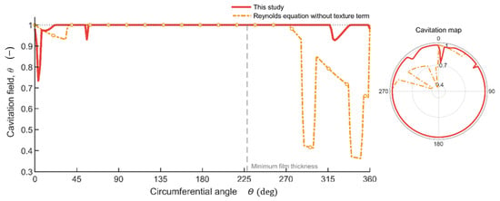
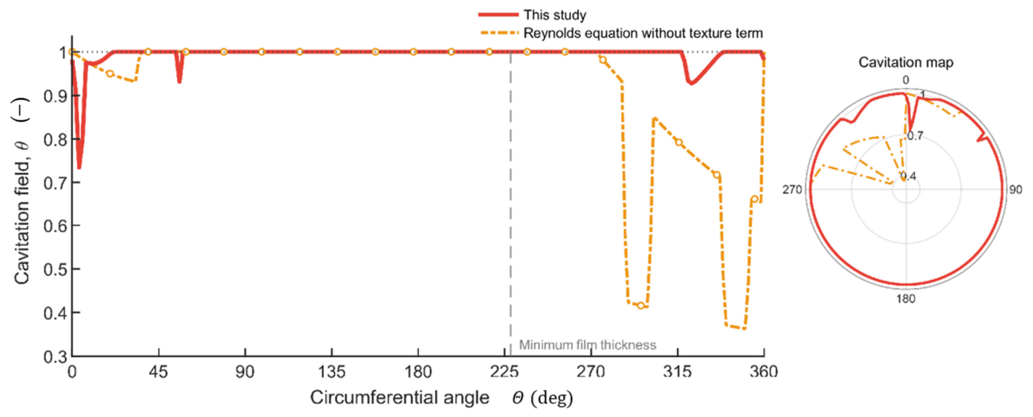
The predicted fluid-fraction field, shown in Figure 7, is consistent with this interpretation. At the circumferential location of the pressure-reformation peak (approximately 300°), the proposed formulation predicts a fluid fraction of 1, whereas Equation (1) predicts 0.54, a cavitated state that cannot generate the peak. Since Anjos et al. [24] did not report the fluid-fraction field, the agreement in pressure provides only indirect support for the predicted film reformation.
Figure 7.
Case 2 : fluid-fraction distribution ( along the bearing centerline predicted by the proposed formulation, Equation (8), and by the textured-bearing Reynolds equation, Equation (1), which omits the texture-motion term.
5.3. Application to Water-Lubricated Conditions
To illustrate the application of the formulation under water-lubricated conditions, the Case 2 configuration was recomputed with water at 25 °C as the lubricant. The bearing geometry, chevron texture, journal speed, supply-groove condition, and axial ambient-pressure boundaries of Case 2 were retained, and two prescribed eccentricity ratios, and , were examined. The solution was obtained on a 257 × 65 node grid, and the results correspond to the end of the third journal revolution (t = 0.060 s), by which time the periodic solution was established.
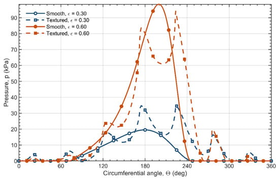
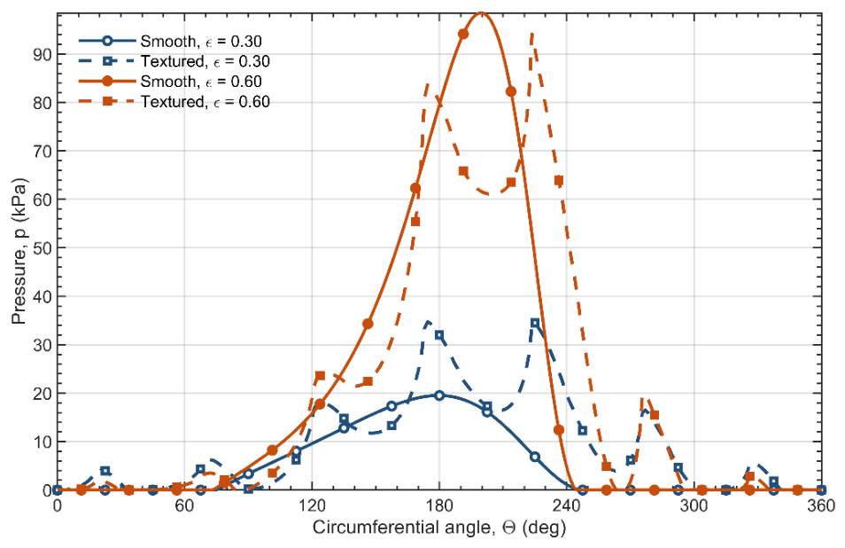
Figure 8 compares the pressure distributions for the smooth and textured journals. At , the chevrons produce distinct local pressure rises and increase the peak pressure from 19.57 to 34.62 kPa. At , the texture still produces visible local modulation, but it redistributes the main pressure field and reduces the peak pressure from 99.58 to 94.79 kPa. A chevron texture that markedly increases the peak pressure at low eccentricity thus has a slightly adverse effect at the higher eccentricity typical of water-lubricated bearings. This confirms that the effect of journal textures depends strongly on the operating conditions and that texture designs for water-lubricated bearings must be tailored to the intended operating regime.
Figure 8.
Pressure distributions for smooth and textured journals in Case 2 lubricated with water at prescribed eccentricity ratios and , at the end of the third journal revolution .
5.4. Computational Efficiency
To quantify the computational advantage of the journal-fixed formulation, the Case 2 configuration was also solved with a classical global-frame formulation on a fixed grid, in which the chevron texture is transported across the grid and its geometry is regenerated at each time step. In the present formulation, by contrast, the grid rotates together with the journal, so the texture remains fixed on the grid. Both formulations used the same solver, grid size, time step, and convergence tolerances and they predicted practically the same pressure distribution as detailed in Appendix E. For one periodic revolution, the journal-fixed formulation required 563.5 s of CPU time, compared with 1214.7 s for the global-frame formulation, a reduction of 53.6%. The journal-fixed formulation is therefore advantageous for repeated calculations such as parametric studies and texture optimization.
Further work should apply the formulation systematically to the high-eccentricity, water-lubricated conditions that motivate this study, where the higher eccentricity strengthens the hydrodynamic wedge effect relative to the texture contribution and extends the cavitation region. Since the texture term in Equation (5) is proportional to the circumferential gradient of the texture depth, whereas the wedge term is proportional to that of the nominal film thickness, the relative importance of the journal texture is expected to increase with the ratio of the texture depth to the eccentricity-induced clearance variation, . The texture density and geometry determine the number, spacing, and orientation of the texture edges at which these gradients act, and, for inclined edges, such as those of chevrons, the orientation also sets the direction of the axial pumping, which either retains the lubricant in the film or expels it [24]. A systematic assessment over a broader range of texture geometries, texture-depth-to-clearance ratios, eccentricity ratios, and operating speeds is also required to establish the range of applicability, together with experimental validation and a quantitative comparison of computational cost against moving-mesh formulations.
6. Conclusions
This study implemented and numerically verified a transient Reynolds formulation for journal bearings with surface textures on the rotating journal. While the governing equation is equivalent to that of Jang and Yoon [22], the texture-advection contribution was expressed here as an explicit source term and incorporated into the mass-conserving p–θ algorithm on a finite-difference grid fixed to the journal. This term arises from the motion of the texture relative to the eccentricity-induced clearance profile, and it has the opposite sign to the texture term of the textured-bearing case. The formulation allows cavitating problems with rotating textures to be solved without a moving mesh and the texture-motion effect to be isolated by omission. For the chevron-textured bearing of Case 2, solving on a grid that rotates with the journal reduced the CPU time by 53.6% relative to a classical fixed global grid, with practically the same pressure distribution.
Two numerical verification cases were examined. In Case 1, a long bearing (L/D = 10) with a single axial channel and no cavitation boundary condition was used to isolate the texture-motion contribution. The proposed formulation followed the independent Navier–Stokes CFD solution over a full journal revolution, with a maximum discrepancy of 2% in load. More importantly, omitting the texture-motion term produced a phase-inverted load response, predicting a maximum at the angular position where the proposed formulation and the CFD predicted a minimum, and vice versa. This qualitative error leads to incorrect conclusions regarding texture performance.
In Case 2, a finite-length bearing (L/D = 0.5) with seven chevron features and a JFO cavitation boundary condition was analyzed. The proposed formulation reproduced the pressure distribution of Anjos et al. [24], who represented shaft-texture motion using a moving multigrid algorithm.
The present study has several limitations. Both verification cases use relatively low eccentricity ratios, and only two texture configurations are examined. The sensitivity of the texture-motion contribution to texture density, depth-to-clearance ratio and operating conditions has not been assessed systematically. Future parametric studies should identify when this contribution is significant and provide practical guidance for texture design. An illustrative calculation with water properties showed that the chevron texture increased the peak pressure at but reduced it at . A systematic evaluation under water-lubricated conditions is still required before the applicability of the formulation to practical water-lubricated journal bearings can be established.
Author Contributions
Conceptualization, A.D.; Methodology, A.D. and M.G.; Software, A.D.; Validation, A.D. and I.C.; Formal analysis, A.D.; Investigation, A.D.; Resources, A.D.; Data curation, A.D.; Writing—original draft, A.D.; Writing—review & editing, R.G. and M.G.; Visualization, A.D.; Supervision, R.G. and M.G. All authors have read and agreed to the published version of the manuscript.
Funding
This research was funded by Israel Ministry of Innovation, Science and Technology, Israel grant number 100170328.
Data Availability Statement
The original contributions presented in this study are included in the article. Further inquiries can be directed to the corresponding author.
Acknowledgments
This study was supported by the Israel Ministry of Innovation, Science and Technology, Israel (Grant No. 100170328).
Conflicts of Interest
The authors declare no conflict of interest.
Abbreviations
The following abbreviations are used in this manuscript:
| CFD | Computational fluid dynamics |
| WLJBs | Water-lubricated journal bearings |
| JFO | Jakobsson–Floberg–Olsson |
| FDM | Finite-difference method |
| SOR | Successive over-relaxation |
| RMSE | Root-mean-square error |
| CPU | Central Processing Unit |
| LST | Laser Surface Texturing |
| GA-ANN | Genetic Algorithm–Artificial Neural Network |
Nomenclature
The following symbols are used in this manuscript:
| C | Radial clearance [m] |
| D | Bearing diameter [m] |
| e | Journal eccentricity [m] |
| Fr′, Ft′ | Hydrodynamic force components in the journal-fixed radial and tangential directions [N] |
| Fr, Ft | Hydrodynamic force components in the rotated radial and tangential directions [N] |
| Fx, Fy | Hydrodynamic force components in the global coordinate system [N] |
| h | Nominal film thickness [m] |
| hT | Total film thickness [m] |
| L | Bearing length [m] |
| Nx | Number of texture features around the journal circumference [–] |
| Nz | Number of texture features in the axial direction [–] |
| P | Hydrodynamic pressure [Pa] |
| Pcav | Cavitation pressure [Pa] |
| R | Bearing radius [m] |
| r* | Journal radius [m] |
| t | Time [s] |
| U | Circumferential surface speed [m s−1] |
| UJ, UB | Journal and bearing surface speeds, respectively [m s−1] |
| W | Applied load [N] |
| w | Texture width [m] |
| x, y | Global Cartesian coordinates [m] |
| z | Axial coordinate [m] |
| Normalized pressure and fluid-fraction convergence errors [–] | |
| F, Fsmooth | Hydrodynamic-force magnitude and corresponding smooth-journal value [N] |
| Nα | Number of circumferential control volumes [–] |
| Np | Number of pressure-comparison points [–] |
| OJ | Journal center |
| Pi, Pref,i, Pref,max | Predicted pressure, reference pressure, and maximum reference pressure [Pa] |
| pα | Angular pitch between successive chevrons [rad] |
| Greek symbols | |
| Circumferential coordinate measured from the line of centers [rad] | |
| αs0 | Initial angular position of the first chevron in the global coordinate system [rad] |
| αs,l(t) | Angular position of chevron l at time t [rad] |
| Circumferential coordinate in the journal-fixed frame [rad] | |
| δB | Bearing texture depth [m] |
| δJ | Journal texture depth [m] |
| Eccentricity ratio, e/C [–] | |
| Fluid fraction [–] | |
| Θ | Circumferential coordinate measured from the load line [rad] |
| Dynamic viscosity [Pa·s] | |
| Lubricant density [kg/m3] | |
| Attitude angle [rad] | |
| Chevron angle [deg] | |
| Angular velocity [rad s−1] | |
| Convected circumferential coordinate [rad] | |
| Other notation | |
| Δα | Circumferential grid spacing in rotated global coordinate frame [rad] |
| Δβ | Circumferential grid spacing in journal-fixed coordinate frame [rad] |
| Δz | Axial grid spacing [m] |
| Δt | Time step [s] |
| i, j | Circumferential and axial grid indices [–] |
| k | Time-step index [–] |
| q | Inner SOR iteration index [–] |
| l | Chevron index [–] |
| m, n | Numbers of circumferential and axial grid points [–] |
| (r, t) | Rotated radial–tangential coordinate frame |
| (r′, t′) | Journal-fixed coordinate frame |
| ′ | Quantity expressed in the journal-fixed coordinate system |
Appendix A. Reynolds Source Terms for Rotating-Journal and Stationary-Bearing Textures
This appendix derives the Reynolds equation for two configurations: a texture attached to the rotating journal and a texture attached to the stationary bearing. The derivations show how surface motion affects the time derivative of the total film thickness and, consequently, the sign of the texture contribution in the Reynolds equation source term.
Appendix A.1. Derivation of the Reynolds Equation for a Textured Journal
The derivation begins with the Reynolds equation written in the stationary global frame [29], using the circumferential coordinate α and the axial coordinate z:
Here, is the hydrodynamic pressure, is the dynamic viscosity, R is the radius of the bearing, and is the total film thickness. For further clarification of the notation, see Section 2.
In the global frame, the bearing is stationary while the journal surface moves with the circumferential speed U:
The total film thickness is decomposed into the nominal smooth clearance, h, and the texture-induced perturbation:
This representation separates the nominal clearance, which is stationary in the global frame, from the texture profile transported with the rotating journal. The transient term on the right-hand side of Equation (A1) is obtained by differentiating the total film thickness with respect to time at a fixed location in the global frame.
The nominal film thickness is stationary in the global frame, so:
Combining Equations (A4) and (A5) and applying the chain rule yields the time derivative of the total film thickness at a fixed location in the global frame:
The negative sign arises because the texture moves in the direction of increasing α, so at a fixed global location the film thickness changes in proportion to the negative of the texture gradient.
The global-frame velocities and film-thickness time derivatives, Equations (A2)–(A6), are now substituted into the Reynolds equation:
This form contains the conventional wedge term, based on the total film thickness and the additional texture-transport term generated by journal rotation.
Collecting the circumferential derivatives gives the final global-frame pressure equation for a bearing with a textured journal:
The resulting source term contains the nominal film-thickness gradient and the texture gradient with opposite signs, distinguishing the classical wedge contribution from the contribution of the moving texture.
Appendix A.2. Derivation of the Reynolds Equation for a Textured Bearing in the Global Frame
For the textured-bearing configuration, the behavior is the opposite: the nominal film-thickness gradient and the texture gradient are additive. This follows directly from the Reynolds equation [29].
Here, is the hydrodynamic pressure, is the dynamic viscosity, R is the radius of the bearing, and is the total film thickness.
In this case the total film thickness is decomposed into the nominal smooth clearance, h, and the texture-induced perturbation on the bearing:
In contrast to the textured-journal case of Equation (A3), the texture here is fixed to the stationary bearing, so the total film thickness is stationary in the global frame and, under the constant-eccentricity assumption of Section 2.1, its time derivative vanishes:
The resulting Reynolds equation is:
The difference between the two configurations arises from the motion of the texture relative to the global frame. For a textured bearing, the texture is stationary so its gradient adds to the classical wedge term. For a textured journal, the texture is transported through the frame introducing a time-dependent contribution whose gradient subtracts from the wedge term.
Appendix B. Reynolds Equation for a Textured Journal in the Journal-Fixed Frame
This appendix derives the Reynolds equation for a bearing with a textured journal in the journal-fixed frame, in which the texture is stationary and the nominal bearing geometry moves through the coordinate system. Here β is the circumferential coordinate and primed quantities denote journal-fixed descriptions. The motivation, notation, and governing parameters are introduced in Section 2.
Here, is the hydrodynamic pressure, is the dynamic viscosity, R is the radius of the bearing, and is the total film thickness.
In the journal-fixed frame, the journal surface is stationary and the bearing moves in the negative circumferential direction with speed U.
The journal-fixed film thickness is decomposed into the nominal film thickness, which moves through the frame, and the texture contribution, which is stationary in it:
Differentiating the total film thickness at fixed β therefore leaves only the contribution of the nominal film thickness:
The texture is stationary in the rotating coordinate system; therefore:
Combining Equations (A16) and (A17) and applying the chain rule gives the film-thickness time derivative at fixed β in the journal-fixed frame:
The positive term represents transport of the nominal film thickness through the journal-fixed frame in contrast to the negative sign obtained in Equation (A6), where the texture is transported through the global frame.
Substituting the transformed surface velocities and transient term into the journal-fixed frame gives the following Reynolds equation formulation:
Expanding the total film-thickness derivative separates the nominal film-thickness and texture contributions. Collecting like derivatives gives the final journal-fixed equation:
The pressure source has the same physical content as the global-frame expression in Equation (A8): a nominal film-thickness wedge contribution and an oppositely signed texture-gradient contribution evaluated at the same physical location.
Four limiting cases were used as consistency checks, and each was satisfied. Removing the texture recovers the classical Reynolds equation for a smooth journal bearing. A uniform nominal film thickness isolates the pressure generation associated with the moving texture. With the journal speed set to zero and no squeeze motion imposed, both the wedge and texture-transport contributions vanish. Transforming the primed variables back to the global frame recovers Equation (A8) exactly, confirming the signs, coefficients, and coordinate transformation.
For the cavitating case considered here, the JFO boundary condition is implemented using the model:
Applying the chain rule and substituting Equation (A18) into Equation (A21) gives the explicit form used above:
Appendix C. CFD Model for Case 1
A finite-volume CFD model implemented in ANSYS Fluent 2021 R1 was used to solve the Navier–Stokes equations and independently verify Case 1 without cavitation. The mesh was generated with the commercial software ANSYS ICEM CFD 2021 R1. The model is two-dimensional, representing an axially uniform circumferential section, which is consistent with the long-bearing configuration of Case 1. The geometry and computational mesh are shown in Figure A1. The outer boundary represents the lubricant adjacent to the bearing, and the inner boundary the lubricant adjacent to the textured journal with the channel outlined in red. The mesh comprises 1080 quadrilateral elements in the circumferential direction, 10 layers across the nominal film thickness, and one additional layer within the channel. A time step of 0.001 s was used. Mesh refinement and time-step reduction changed the predicted load-carrying capacity by less than 1%, indicating spatial and temporal convergence.
Figure A1.
Case 1 CFD model: (a) computational mesh near the channel edge; (b) geometry and imposed kinematics.
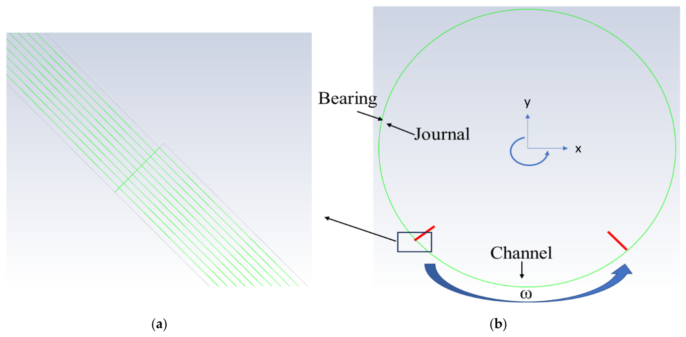
Modeling the transient transport of the textured region is numerically challenging. Although a sliding-mesh approach is, in principle, suitable for modeling rotating textured geometries, it was found to introduce non-negligible errors due to node mismatch at the interface between the rotating and stationary zones.
To avoid these errors, an equivalent kinematic transformation was adopted in which the journal was kept stationary and the motion imposed on the bearing. This configuration preserves the relative motion of the two surfaces and the instantaneous film-thickness distribution, so the two configurations are equivalent under the assumptions of the present model, stated in Section 2.2.
In this framework, the bearing rotates with angular velocity opposite to the direction of the physical journal rotation, while its center undergoes a circular orbit of radius around the fixed journal center. The angular velocity of this orbital motion equals , preserving a constant eccentricity ratio and reproducing the correct time-dependent transport of the surface texture through the converging and diverging regions. The rotational motion of the bearing wall was imposed using a moving-wall boundary condition, whereas the orbital motion of the bearing center was imposed using the dynamic mesh technique. A stationary-wall boundary condition was applied to the journal. The boundary conditions are summarized in Table A1. Further details of the governing equations solved in the CFD model are provided in [30].
Table A1.
Boundary conditions of the Case 1 CFD model.
Appendix D. Grid Independence and Numerical Parameters
Figure A2 presents the grid-independence study for Case 1. Nodal grids ranging from 18 × 8 (144 nodes) to 360 × 160 (57,600 nodes) were examined. The coarsest grids exhibited noticeable discretization errors relative to the finest grid, whereas the load predicted with the 180 × 80 grid differed from the 360 × 160 reference solution by only 0.017%. The 180 × 80 grid was therefore selected for Case 1. The same procedure was applied to Case 2, for which the 257 × 65 grid was selected.
Figure A2.
Case 1 grid independence: normalized load and its difference from the 360 × 160 reference grid.
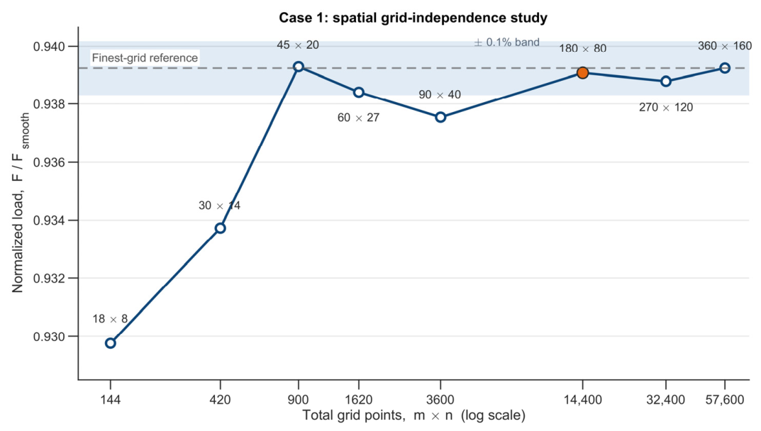
The numerical parameters used for the two cases are summarized in Table A2.
Table A2.
Numerical parameters for Cases 1 and 2.
Appendix E. Computational Efficiency Comparison with a Global-Frame Formulation
To isolate the computational cost associated with the choice of reference frame, the Case 2 configuration was also solved with a classical global-frame formulation, in which the computational grid is fixed in the rotated global frame (r, t) and the journal texture is transported across it. In this frame, α is measured from the line of centers, and the governing equation is written in the conservative mass-conserving form:
where the time derivative is evaluated at a fixed global location α. The nominal film thickness is stationary in this frame,
and was therefore calculated once. The journal texture, however, moves with the journal, so its contribution to the film thickness must be re-evaluated at a new circumferential position at every time step.
Figure A3 defines the circumferential placement of the periodic chevron texture on the unwrapped journal surface, and .
Figure A3.
Geometric definition of the periodic chevron texture on the unwrapped journal surface at . The first chevron is placed at the phase measured from the global origin .
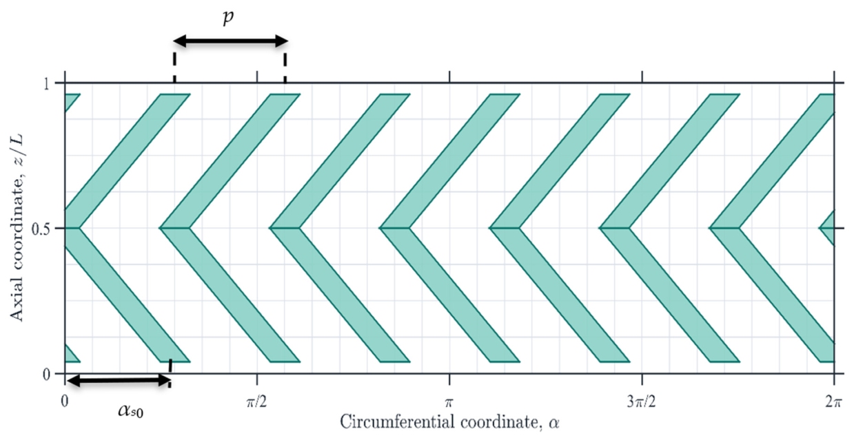
The circumference is divided into identical pitch cells, giving an angular pitch . At , the first chevron is placed at the phase , measured from the global origin , with and the remaining chevrons are positioned successively at the pitch . As the journal rotates, every chevron undergoes the same angular displacement , so that the position of the l-th chevron is:
At each time step, the chevron polygons are regenerated at these positions and the resulting film-thickness field is passed to the p–θ solver. The time step is with where is the number of circumferential cells, so that after time steps the texture completes one revolution and returns to its initial phase. The convergence criteria of Equations (14) and (15) were applied to both formulations. Figure A4 compares the circumferential pressure distributions obtained with the two formulations as a function of the angle measured from the load line.
Figure A4.
Circumferential pressure distributions for Case 2 predicted with the journal-fixed and global-frame formulations. The angle is measured from the load line.
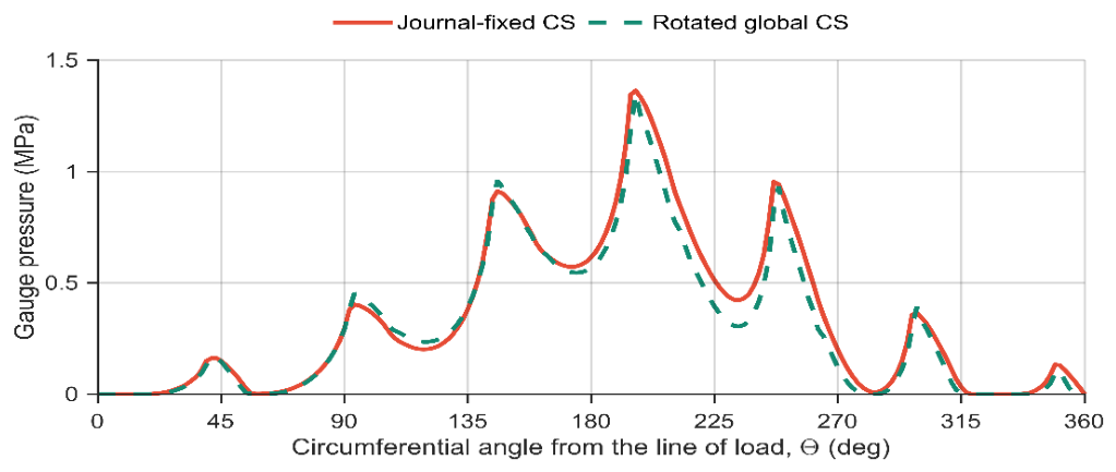
Both formulations predict the same pressure-peak locations and reproduce the pressure variations generated by the chevrons, with minor discrepancies near local pressure maxima and in regions of steep pressure gradients due to the frame-dependent discretization. The comparison was performed on a 257 × 65 node grid with (256 time steps per revolution) and identical convergence tolerances. The reported timings correspond to one periodic revolution and include the complete geometry update and solution. All calculations were performed in MATLAB (2020) on a computer with an Intel Core i5-10310U processor (1.70 GHz nominal frequency, eight logical processors). The journal-fixed formulation required 563.5 s of CPU time, whereas the global-frame formulation required 1214.7 s. The additional cost of the global-frame formulation arises from regenerating the chevron polygons at all 256 positions and from the additional iterations required near the moving texture edges.
References
- Litwin, W. Water-Lubricated Bearings of Ship Propeller Shafts—Problems, Experimental Tests and Theoretical Investigations. Pol. Marit. Res. 2009, 16, 42–50. [Google Scholar] [CrossRef] [Scilit]
- Nosonovsky, M.; Bhushan, B. (Eds.) Green Tribology: Biomimetics, Energy Conservation and Sustainability; Green Energy and Technology; Springer: Berlin/Heidelberg, Germany, 2012; ISBN 978-3-642-23680-8. [Google Scholar]
- Dov, A.; Groper, M. Experimental Investigation of Lubrication Regimes of a Water-Lubricated Bearing in the Propulsion Train of a Marine Vessel. J. Tribol. 2021, 143, 041803. [Google Scholar] [CrossRef] [Scilit]
- Kumar, P.; Yadav, J.; Kunwer, R. Advancements and Challenges in Water-Lubricated Bearings for Marine Applications: A Comprehensive Review. Tribol. Online 2025, 20, 1–25. [Google Scholar] [CrossRef] [Scilit]
- Chen, S.; Li, J.; Wei, L.; Jin, Y.; Shang, H.; Hua, M.; Duan, H. Tribological Properties of Polyimide-Modified UHMWPE for Bushing Materials of Seawater Lubricated Sliding Bearings. Tribol. Int. 2017, 115, 470–476. [Google Scholar] [CrossRef] [Scilit]
- Ganesha, A.; Joseph, A.; Pai, R.; Khader, S.M.A.; Kumar, N.; Kumar, S.; Girish, H. Performance Optimization of a Multi-Groove Water Lubricated Journal Bearing with Partial Slip by Taguchi Analysis. Arab. J. Sci. Eng. 2024, 49, 2249–2267. [Google Scholar] [CrossRef] [Scilit]
- Shinde, A.B.; Chavan, S.P. Parametric Investigation of Surface Texturing on Performance Characteristics of Water Lubricated Journal Bearing Using FSI Approach. SN Appl. Sci. 2020, 2, 36. [Google Scholar] [CrossRef] [Scilit]
- Mishra, S.; Aggarwal, S. A Review of Performance of Textured Journal Bearing. Tribol. Online 2023, 18, 494–507. [Google Scholar] [CrossRef] [Scilit]
- Ohdar, S.K.; Behera, S.K. A Comprehensive Review on Advancements in Water-Lubricated Bearings: Surface Texture, Tribological Performance, and Thermal Effects. Proc. Inst. Mech. Eng. Part J J. Eng. Tribol. 2025, 239, 955–984. [Google Scholar] [CrossRef] [Scilit]
- Pei, X. Scale Effects of Surface-Texture Distribution on Lubrication and Friction. Tribol. Lett. 2025, 73, 86. [Google Scholar] [CrossRef] [Scilit]
- Ohdar, S.K.; Behera, S.K. Performance Analysis and Optimization of Water-Lubricated Herringbone Groove Journal Bearings: A Novel GA-ANN Approach. Proc. Inst. Mech. Eng. Part J J. Eng. Tribol. 2026, 240, 1133–1153. [Google Scholar] [CrossRef] [Scilit]
- Etsion, I. State of the Art in Laser Surface Texturing. J. Tribol. 2005, 127, 248–253. [Google Scholar] [CrossRef] [Scilit]
- Lu, X.; Khonsari, M.M. An Experimental Investigation of Dimple Effect on the Stribeck Curve of Journal Bearings. Tribol. Lett. 2007, 27, 169–176. [Google Scholar] [CrossRef] [Scilit]
- Jamwal, G.; Sharma, S.; Awasthi, R.K. The Dynamic Performance Analysis of Chevron Shape Textured Hydrodynamic Bearings. Ind. Lubr. Tribol. 2019, 72, 1–8. [Google Scholar] [CrossRef] [Scilit]
- Tala-Ighil, N.; Fillon, M. Surface Texturing Effect Comparative Analysis in the Hydrodynamic Journal Bearings. Mech. Ind. 2015, 16, 302. [Google Scholar] [CrossRef] [Scilit]
- Brizmer, V.; Kligerman, Y. A Laser Surface Textured Journal Bearing. J. Tribol. 2012, 134, 031702. [Google Scholar] [CrossRef] [Scilit]
- Tala-Ighil, N.; Fillon, M.; Maspeyrot, P. Effect of Textured Area on the Performances of a Hydrodynamic Journal Bearing. Tribol. Int. 2011, 44, 211–219. [Google Scholar] [CrossRef] [Scilit]
- Li, P.; Zeng, F.; Xiao, S.; Zhen, D.; Zhang, H.; Shi, Z. Effects of Texture Bottom Profile on Static and Dynamic Characteristics of Journal Bearings. Shock Vib. 2021, 2021, 7068744. [Google Scholar] [CrossRef] [Scilit]
- Manser, B.; Belaidi, I.; Hamrani, A.; Khelladi, S.; Bakir, F. Texture Shape Effects on Hydrodynamic Journal Bearing Performances Using Mass-Conserving Numerical Approach. Tribol. Mater. Surf. Interfaces 2020, 14, 33–50. [Google Scholar] [CrossRef] [Scilit]
- Hirs, G.G. The Load Capacity and Stability Characteristics of Hydrodynamic Grooved Journal Bearings. ASLE Trans. 1965, 8, 296–305. [Google Scholar] [CrossRef] [Scilit]
- Jang, G.H.; Chang, D.I. Analysis of a Hydrodynamic Herringbone Grooved Journal Bearing Considering Cavitation. J. Tribol. 2000, 122, 103–109. [Google Scholar] [CrossRef] [Scilit]
- Jang, G.H.; Yoon, J.W. Nonlinear Dynamic Analysis of a Hydrodynamic Journal Bearing Considering the Effect of a Rotating or Stationary Herringbone Groove. J. Tribol. 2002, 124, 297–304. [Google Scholar] [CrossRef] [Scilit]
- Cupillard, S.; Cervantes, M.J.; Glavatskih, S. Thermohydrodynamic Analysis of a Journal Bearing with a Microgroove on the Shaft. Comput. Therm. Sci. 2014, 6, 47–57. [Google Scholar] [CrossRef] [Scilit]
- dos Anjos, L.F.; Jaramillo, A.P.; Buscaglia, G.C.; Nicoletti, R. Improving the Load Capacity of Journal Bearings with Chevron Textures on the Shaft Surface. Tribol. Int. 2023, 185, 108561. [Google Scholar] [CrossRef] [Scilit]
- Khonsari, M.M.; Booser, E.R. Applied Tribology: Bearing Design and Lubrication, 2nd ed.; John Wiley & Sons Ltd.: Chichester, UK, 2008; ISBN 978-0-470-05711-7. [Google Scholar]
- Xu, W.; Zhao, S.; Xu, Y.; Li, K. Reynolds Model versus JFO Theory in Steadily Loaded Journal Bearings. Lubricants 2021, 9, 111. [Google Scholar] [CrossRef] [Scilit]
- Ausas, R.F.; Jai, M.; Buscaglia, G.C. A Mass-Conserving Algorithm for Dynamical Lubrication Problems with Cavitation. J. Tribol. 2009, 131, 031702. [Google Scholar] [CrossRef] [Scilit]
- Cohen, I.; Goltsberg, R. Partial Surface Texturing in Hydrodynamic Lubrication: A CFD-Based Investigation. Lubricants 2023, 11, 395. [Google Scholar] [CrossRef] [Scilit]
- Hamrock, B.J. Fundamentals of Fluid Film Lubrication; NASA Reference Publication 1255; National Aeronautics and Space Administration: Washington, DC, USA, 1991. [Google Scholar]
- ANSYS, Inc. ANSYS Fluent Theory Guide; Release 2021 R1; ANSYS, Inc.: Canonsburg, PA, USA, 2021. [Google Scholar]

Disclaimer/Publisher’s Note: The statements, opinions and data contained in all publications are solely those of the individual author(s) and contributor(s) and not of MDPI and/or the editor(s). MDPI and/or the editor(s) disclaim responsibility for any injury to people or property resulting from any ideas, methods, instructions or products referred to in the content. |
© 2026 by the authors. Licensee MDPI, Basel, Switzerland. This article is an open access article distributed under the terms and conditions of the Creative Commons Attribution (CC BY) license.