


Abstract
This study presents a numerical framework for analyzing mixed elastohydrodynamic lubrication (EHL) of rough contact surfaces under grease lubrication, motivated by the need for reliable lubrication design in tribological components such as mechanical face seals and rolling bearings operating in space environments. Considering surface roughness effects, the proposed method integrates an EHL model derived from the Ostwald constitutive equation with the Kogut–Etsion (KE) elastic–plastic asperity contact model. The methodology is demonstrated through a case study of a vacuum grease-lubricated double-row angular contact ball bearing employed in a spacecraft antenna rotation mechanism under low-speed and heavy-load conditions. The governing equations were non-dimensionalized and solved numerically to obtain the lubricant film thickness and pressure distributions under various rotational speeds and axial preloads. The friction torque generated by viscous shear of the lubricant and asperity contact, and the asperity load ratio, were also determined. The novelty of this work lies in two aspects: (i) the integration of the Ostwald grease rheology model and the KE elastic–plastic asperity contact model into a unified mixed EHL framework; and (ii) a systematic investigation of grease-lubricated bearing behavior at low rotational speeds (11.5–55.2 rpm) with explicit consideration of surface roughness. The results indicate that rotational speed and axial preload exert limited influence on film thickness. The film pressure along the rolling direction increases with speed, whereas the asperity contact pressure decreases with speed and increases with preload; the asperity load ratio follows the same trends. The fluid pressure exhibits a single peak on the inlet side of the contact, and no outlet film constriction is observed in the thickness profile. The friction torque decreases with increasing speed, and the asperity load ratio follows the same trend. These findings demonstrate that appropriate adjustment of preload and an increase in rotational speed can reduce both friction torque and the asperity load ratio, thereby improving lubrication conditions and extending bearing service life.
1. Introduction
Double-row angular contact ball bearings consist of an inner ring that rotates with the shaft and a stationary outer ring, with rolling balls positioned between the inner and outer raceways. The friction between the inner raceway and the balls drives the rolling motion of the balls. Compared with single-row angular contact ball bearings, double-row configurations provide greater rigidity and can support axial loads in both directions within a compact arrangement. Angular-contact ball bearings are used in spacecraft rotating mechanisms, including antenna gimbals, where long life and reliable lubrication are essential [1].
With the advancement of spacecraft technology, the operational lifetime requirements for space antenna mechanisms have become increasingly demanding. Spacecraft mechanisms must maintain reliable tribological performance under vacuum and temperature extremes, and lubricant selection must account for volatility, material compatibility, friction, and mission life [2]. Grease is one lubricant form considered for long-life mechanisms, although its suitability depends on the bearing design and operating environment. However, space antenna rotation mechanisms typically operate at low rotational speeds under substantial inertial loads. Moreover, bearing working surfaces are not perfectly smooth at the microscopic scale; direct contact between surface asperities occurs, meaning that the pressure transmission between the two contact surfaces is jointly borne by the lubricant film and asperity contacts—i.e., a mixed lubrication regime. Consequently, achieving long-life rotation necessitates meticulous lubrication design.
For engineering surfaces, the effect of surface roughness is unavoidable. Therefore, mixed lubrication on rough surfaces represents a fundamental challenge common to numerous mechanical components. Deterministic models of rough point contacts explicitly couple hydrodynamic pressure with asperity contact pressure and load sharing. Mechanical face seals, which are critical for fluid containment in rotating machinery ranging from aerospace propulsion systems to industrial pumps, can likewise operate with load shared between the hydrodynamic lubricant film and microscopic asperity contacts. The governing mechanisms—including elastohydrodynamic pressure generation, elastic–plastic asperity deformation, and lubricant rheology—are shared by rough-surface rolling contacts and mechanical face seals. Despite these common underlying physics, numerical frameworks that explicitly couple non-Newtonian grease rheology with elastic–plastic asperity contact mechanics have seldom been generalized across these application domains. A unified analysis methodology applicable to diverse rough-surface lubricated contacts is therefore of considerable engineering value.
Previous studies have examined high-speed lubrication and thermal behavior in angular-contact ball bearings [3], as well as angular-contact-bearing kinematics and geometry [4], whereas low-speed operation with explicit surface-roughness effects remains less explored. In the literature, mixed lubrication primarily involves elastohydrodynamic lubrication (EHL) theory and asperity contact models [5]. EHL combines Reynolds theory with Hertzian elastic contact theory to investigate the hydrodynamic lubrication characteristics between two surfaces in relative sliding motion [6]. Asperity contact models address the deformation of contacting asperities on two surfaces under external loading. Notable asperity contact models include the Greenwood–Tripp (GT) statistical contact model [7], the Chang–Etsion–Bogy (CEB) elastic–plastic model [8], the Zhao–Maietta–Chang (ZMC) model incorporating elastic, elastic–plastic, and fully plastic deformation [9], and the Kogut–Etsion (KE) model established using the finite element method [10]. Among these, the KE model has gained increasing adoption owing to its favorable agreement with experimental results.
Recent investigations have substantially advanced the modeling of grease-lubricated mixed EHL contacts. Wu et al. [11] developed a mixed EHL analysis method for greases obeying the Ostwald power-law model and derived film thickness and asperity load formulas for rough contacts, while deterministic mixed lubrication models of rough point contacts have unified the treatment of hydrodynamic and asperity-contact regions across a wide range of film ratios [12]. Mixed EHL frameworks have also been extended to thermal effects in grease-lubricated gear contacts [13] and to the influence of surface topography on plasto-elastohydrodynamic responses in point contacts [14], as well as to contacts containing solid particles [15]. In parallel, capacitance-based measurements in grease-lubricated ball bearings have clarified how film thickness evolves with speed under fully flooded and starved conditions [16], and recent molecular-dynamics and tribological studies have examined grease structure, composition, and friction [17,18]. At low speeds, experiments on ball bearings have further shown that thickener residual layers can contribute substantially to film thickness [19]. In the context of mechanical face seals, the load-sharing concept has been applied to quantify the transition into mixed lubrication on rough seal faces [20]. Despite these advances, an integrated framework that simultaneously couples non-Newtonian Ostwald grease rheology, Bair–Winer shear thinning, and the Kogut–Etsion elastic–plastic asperity model under the ultra-low-speed, heavy-load conditions typical of space mechanisms has not been established, which motivates the present study.
This study presents a general mixed EHL analysis framework for rough-surface grease-lubricated contacts, integrating the Ostwald constitutive equation and the KE asperity contact model into a unified numerical methodology. The capability of this framework is demonstrated through a case study of the 601EF space-grade grease-lubricated double-row angular contact ball bearing employed in a satellite antenna rotation mechanism. The lubricant film thickness and pressure distributions are systematically analyzed under various rotational speeds and axial preloads, with simultaneous calculation of the friction torque generated by lubricant viscous flow and asperity contact, along with the asperity load ratio. While grease-lubricated bearings have been widely investigated under high-speed conditions (1000–10,000 rpm), low-speed operation (11.5–55.2 rpm) with explicit consideration of surface roughness remains comparatively unexplored. Since engineering surfaces are inherently rough, incorporating surface roughness into grease lubrication models provides vital practical guidance. The bearing and grease parameters used in the numerical analysis are derived from materials employed in actual engineering applications, so the numerical results offer direct guidance for experimental work. Whereas previous investigations of grease-lubricated bearings have predominantly addressed high-speed conditions (1000–10,000 rpm), this study examines the lubrication behavior of ball bearings at low speeds (11.5, 30.5, and 55.2 rpm).
The numerical analysis is formulated based on several reasonable physical simplifications. First, given the extremely low operational speeds of the bearing under investigation, the frictional heat generated at the contacting interfaces is minimal, justifying the assumption of isothermal lubrication conditions. Second, relative sliding between the balls and the raceways is neglected, simplifying the kinematics of the rolling elements to unidirectional, pure rolling motion. Finally, the non-Newtonian rheological behavior of the grease is characterized by the Ostwald–de Waele power-law constitutive model, expressed as , where is the shear stress, is the grease viscosity, is the rheological index, and is the fluid shear strain rate.
2. Materials and Methods
2.1. Governing Equations
To compute the film thickness and pressure distributions in elastohydrodynamic lubrication, the Reynolds equation and the elastic deformation equation must be solved simultaneously. In the formulas of this section, all physical quantities are expressed in the International System of units. For rough surfaces, the influence of surface roughness must also be considered. Under these conditions, the total applied load () is shared between the lubricant film () and the asperity contacts (). Depending on the magnitude of the applied load, the directly contacting asperities may undergo elastic deformation, elastic–plastic deformation, or fully plastic deformation. The overall load balance equation can thus be expressed as:
2.1.1. Two-Dimensional Grease Lubrication Reynolds Equation
Based on References [11,21,22], the two-dimensional grease lubrication Reynolds equation derived from the Ostwald model is given by:
where is the rheological index, is the film pressure, is the film thickness, and is the grease density. and are the flow factors [23]:
The viscosity–pressure relationship and density–pressure relationship are expressed as follows:
where is the initial grease viscosity, is the initial grease density, , and .
2.1.2. Film Thickness Equation
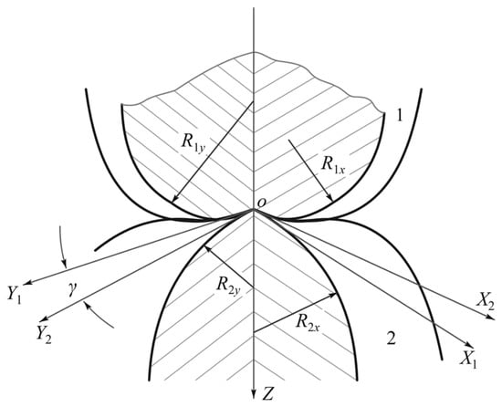
The contact between two arbitrarily shaped bodies can be represented as the contact of an ellipsoid defined by the two principal curvature radii at the contact point. Figure 1 illustrates the geometric relationship in the vicinity of the contact point for two arbitrarily shaped bodies in contact. The principal curvature radii of the two bodies in their respective orthogonal principal planes at the contact point are denoted by , and , . The intersections of the orthogonal principal planes with the common tangent plane define the coordinate axes , and , , with an angle between the two coordinate systems. In engineering practice, the most common elliptical contact scenario involves the principal planes of the two contacting bodies being coincident, i.e., or . Reference [6] indicates that, in such cases, the elliptical contact problem of two elastic bodies can be treated as the contact between an elastic ellipsoid—characterized by equivalent principal curvature radii , and equivalent elastic modulus at the contact point—and a rigid plane.
Figure 1.
General situation of elliptical contact.
When a lubricant film exists between the two surfaces, the film thickness equation can be expressed as:
where , , , and are the elastic moduli and Poisson’s ratios of the upper and lower contact surfaces, respectively.
2.1.3. Contact Parameters
According to Hertzian contact theory, the contact stress within the contact region follows an ellipsoidal distribution. Letting and denote the semi-major and semi-minor axes of the contact ellipse, respectively, and with the major axis aligned with the -direction, the contact stress is given by:
where .
Defining:
where is the ellipticity ratio (ratio of major to minor semi-axes of the contact ellipse), is the principal curvature ratio, and is the complete elliptic integral of the second kind. The values of and are obtained using the highly accurate empirical formulas regressed by Markho [24].
2.1.4. Asperity Contact Model
The KE model classifies asperity deformation into four regimes: fully elastic, elastic–plastic (first and second stages), and fully plastic [25]. The asperity contact pressure is expressed as:
where , , , , , , and .
In these expressions, is the asperity contact pressure; is the surface parameter of the friction pair (typically taken as 0.05); is Poisson’s ratio of the softer material in the friction pair; is the critical interference at the inception of plastic deformation; is the equivalent elastic modulus; is the Brinell hardness; is the asperity radius of curvature; and are the surface roughness values (RMS) of the friction pair; is the film thickness; is the dimensionless distance between the mean asperity height and the mean surface height; is the dimensionless asperity height; and is the asperity height distribution function, assumed to follow a Gaussian probability density distribution: .
The asperity load ratio La quantifies the load percentage contributed by solid contact in mixed lubrication: it is the fraction of the total contact load carried by direct solid–solid asperity contact rather than by the hydrodynamic film. It is calculated as the ratio of the integrated asperity contact pressure to the integrated total contact pressure:
where is the local asperity contact pressure from the KE elastic–plastic model and is the total contact pressure.
2.2. Calculation of Basic Lubrication Parameters
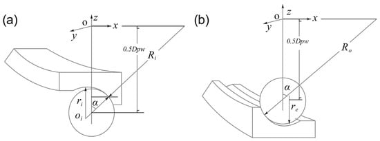
The geometric model of a single angular contact ball bearing within the double-row configuration is shown in Figure 2 [26]. is the pitch diameter of the ball set, is the inner groove curvature radius, is the outer groove curvature radius, and is the ball diameter.
Figure 2.
Geometric model of the double-row angular contact ball bearing: (a) model for inner raceway; (b) model for outer raceway.
2.2.1. Load Calculation
For an idealized angular-contact ball-bearing model subjected to a purely axial preload, with equal contact angles and negligible inertial effects, the normal load is assumed to be uniformly distributed among the loaded balls [27]:
where is the total number of balls and is the actual contact angle of the bearing under axial preload [28].
2.2.2. Equivalent Radius of Curvature
It is explicitly noted that for the contact between the convex ball and the concave inner/outer raceways, the curvature radii of the raceways are treated as negative values in the equivalent radius of curvature calculation, so as to correctly represent the internal conformal geometry characteristic of angular contact ball bearings. For the contact between the ball and the inner raceway:
Ball:
Inner raceway:
For the contact between the ball and the outer raceway:
Outer raceway:
The equivalent radii in the and directions are:
2.2.3. Entrainment Velocity
Under the first-order pure-rolling assumption, the entrainment velocity at the inner-race contact is reduced to the corresponding inner-raceway surface velocity [29]:
where is the rotational speed of the shaft.
For the ball undergoing pure rolling on the outer raceway, the entrainment velocity is [30]:
where is the rotational speed of the outer ring. When the outer ring is stationary, , yielding:
The direction of the entrainment velocity on the inner raceway is opposite to that on the outer raceway.
2.2.4. Friction Torque
Since the balls are driven by the inner ring while the outer ring remains stationary, the friction torque is the product of the total friction force on the inner ring and the moment arm. Following the mixed-lubrication decomposition into fluid shear and asperity friction, the friction force in the present model is evaluated as [31]:
where is the shear stress at the grease–solid contact interface, and is the boundary friction coefficient for solid–solid dry contact, taken as 0.2 in this study.
The friction torque is then:
2.3. Non-Dimensionalization of the Governing Equations
Prior to numerical analysis, the fundamental equations of elliptical contact lubrication must be non-dimensionalized. The following dimensionless parameters are introduced:
The dimensionless Reynolds equation becomes:
where
The dimensionless film thickness equation is:
where
The dimensionless load equation is:
2.4. Numerical Method, Boundary Conditions, and Model Limitations
The numerical simulations were carried out with an in-house finite-difference code implemented in Python 3.14.5.
The dimensionless power-law (Ostwald) Reynolds equation is discretized by the finite difference method on a uniform mesh of 313 × 313 nodes over the dimensionless domain X, Y ∈ [−2, 2] (normalized by the Hertzian contact semi-axes), with central differences approximating the pressure gradients. The transverse diffusion term carries its anisotropic weight cxy = (EA/EB)2 = 0.018. The nonlinear algebraic system is solved by outer iterations alternating between the pressure field and the film thickness. Within each outer iteration, the pressure is solved line-by-line along the rolling direction: each row of nodes is solved simultaneously with a tridiagonal Thomas algorithm, followed by a Gauss–Seidel sweep across the rows, with under-relaxation factors of 0.5 and 0.2 applied to the pressure updates in the pressurized and cavitated regions, respectively. A 3 × 3 median filter (mixing factor 0.5) is applied to the pressurized region after each sweep to suppress isolated one-cell pressure spikes; since the median filter is the identity operator on locally linear fields, the converged solution still satisfies the discrete Reynolds system in all smooth regions. The elastic deformation is evaluated by fast Fourier transform convolution with the Boussinesq influence coefficients (verified against direct summation with an agreement ratio of 0.9936), and the KE asperity contact pressure—integrated over the elastic, first and second elastic–plastic, and fully plastic regimes under a Gaussian height distribution—is relaxed with a factor of 0.1. The film shape is updated every five iterations with a damping factor of 0.15, and the rigid-body displacement is updated every 25 iterations by a secant-based load-balance controller with a minimum-step safeguard to satisfy load balance.
The boundary conditions enforce p = 0 at the inlet and side boundaries of the computational domain. At the outlet, the classical Reynolds cavitation condition is applied: the cavitation boundary is located dynamically (the last node where p exceeds 10−6), the pressure beyond it is relaxed to zero, and all transient negative pressures are truncated to zero. Convergence is declared when, between successive outer iterations, the relative change in the fluid pressure falls below 5 × 10⁻³ and the dimensionless load imbalance |1 − W| falls below 1.4 × 10⁻³.
A mesh-refinement study was performed (Table 1) for the representative case of 200 N preload and 30.5 rpm (per-ball load W = 26.578 N, entrainment velocity 0.078 m/s). Refining the mesh from the production 313 × 313 to 625 × 625 changes the asperity load ratio by 0.02% (from 0.6162 to 0.6161), the dimensionless minimum film thickness by 2.3% (from 0.02611 to 0.0255), and the peak asperity contact pressure by 0.1% (from 20.91 to 20.93), indicating that the 313 × 313 mesh is adequate for the quantities of interest.
Table 1.
Mesh-refinement study.
Regarding model limitations, the current framework assumes (i) isothermal and fully flooded conditions, justified by the ultra-low rotational speeds minimizing frictional heat generation; (ii) a quasi-static treatment that neglects transient squeezing and cage–ball interactions; (iii) statistically isotropic Gaussian roughness; (iv) a fixed boundary friction coefficient 0.2.
3. Results and Discussion
The investigated double-row angular contact ball bearing is a customer-specific component tailored for a spacecraft antenna rotation mechanism. The inner and outer raceway materials of the double-row angular contact ball bearing investigated in this study are X30CrMoN15, a martensitic stainless steel, and the ball material is Si3N4 (silicon nitride). The lubricant employed is space-grade Braycote 601EF grease, which consists of Braycote 815Z as the base oil (mass fraction: 70%) with polytetrafluoroethylene (PTFE) powder as the thickener (mass fraction: 30%). The base oil density is 1.8531 g/cm3. The material properties of the two materials are listed in Table 2, the bearing geometric parameters are presented in Table 3, and the operating conditions are provided in Table 4.
Table 2.
Material properties of bearing and raceway materials.
Table 3.
Geometric parameters of the bearing.
Table 4.
Operating conditions of the bearing.
To validate the mathematical framework, the following checks were performed. (i) Mesh independence: refining the mesh from 313 × 313 to 625 × 625 changes the integral quantities of interest by less than 2.3% (Table 1). (ii) Deformation operator: the fast-Fourier-transform evaluation of the elastic deformation agrees with the direct Boussinesq summation to within 0.7%. (iii) Discrete residuals: the converged solutions satisfy the discrete Reynolds system with an average residual of 1.2% of the pressure-scale terms.
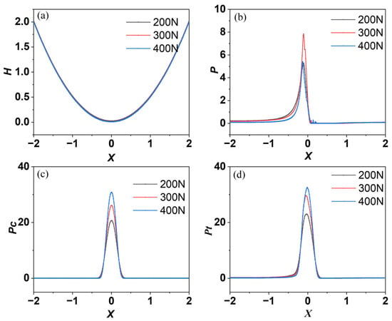
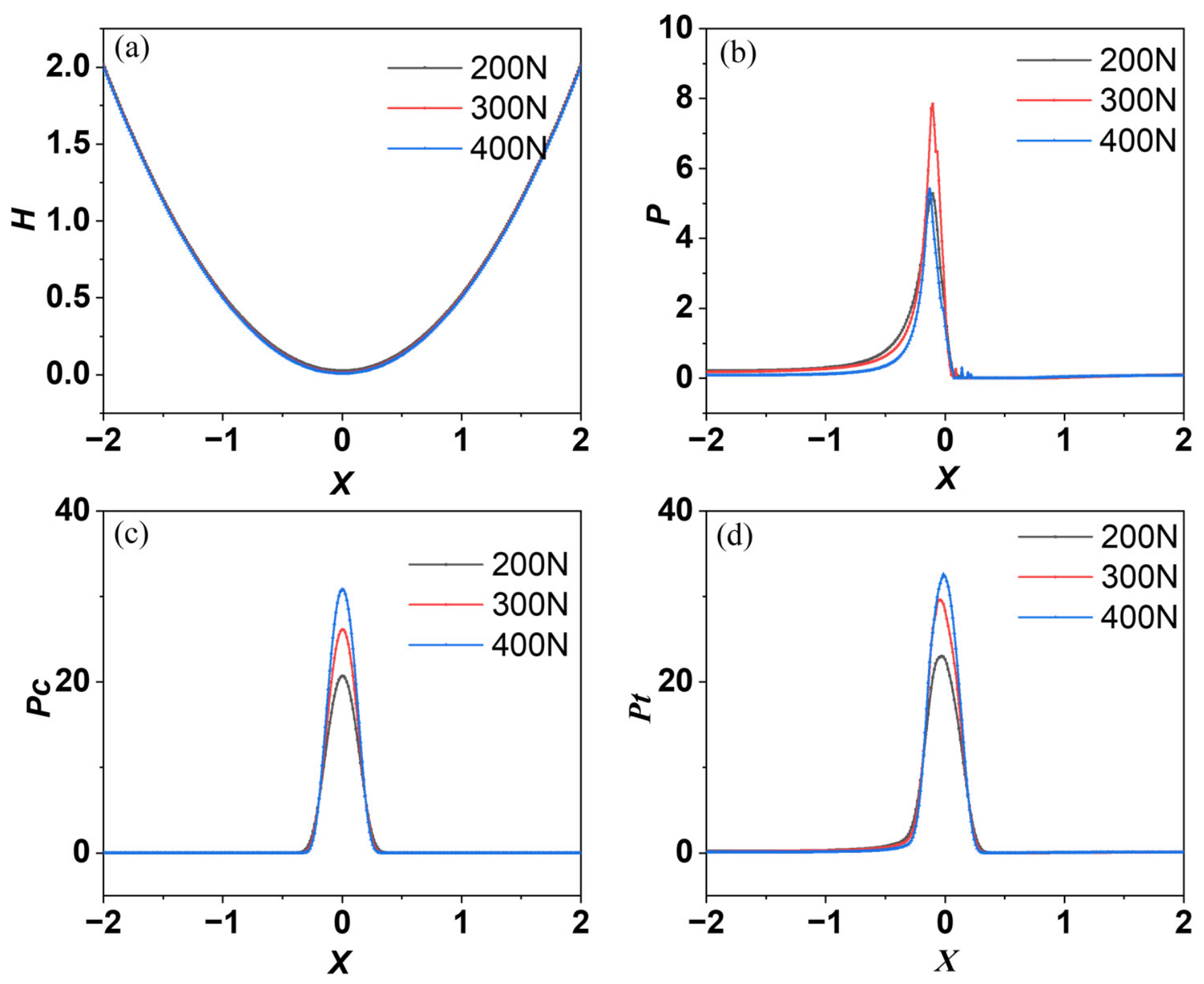
Figure 3 presents the influence of different loads on the film thickness and pressure distributions along the rolling direction of the elliptical contact region (both horizontal and vertical axes are dimensionless parameters). It can be observed that the load exerts comparatively modest influence on the film thickness; however, its effect on the pressure distributions is pronounced. The film thickness shows a single minimum at the contact center (X = 0) and no outlet constriction, while the fluid pressure (Figure 3b) exhibits a single peak on the inlet side of the contact (X ≈ −0.09) and no secondary peak. The absence of the outlet constriction differs from the film constriction behavior reported in the literature for grease-lubricated contacts at the outlet region [32]; as discussed in Section 3, it follows from the contact-dominated mixed regime of the present ultra-low-speed, low-load conditions (the loads corresponding to the three preloads are 26.578 N, 39.867 N, and 53.156 N, respectively; entrainment velocity 0.078 m/s). Both the asperity contact pressure and the total pressure increase with increasing preload. It should be noted that the pressure values presented here correspond only to the rolling direction; thus, the variation in pressure with load shown in this figure reflects the pressure distribution on the symmetry plane.
Figure 3.
Effect of load on (a) grease film thickness, (b) grease pressure, (c) asperity contact pressure, and (d) total pressure along the rolling direction (0.078 m/s, 30.5 r/min).
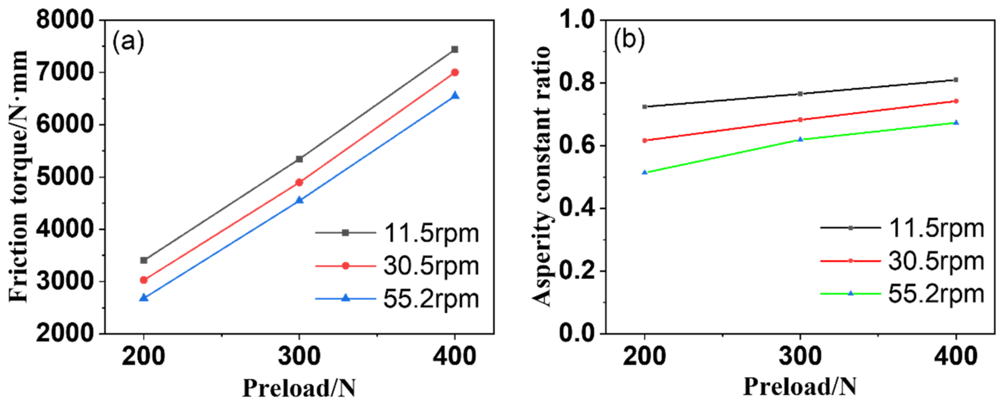
Quantitatively, as the axial preload is raised from 200 to 400 N at 30.5 r/min, the minimum dimensionless film thickness decreases from 0.02611 to 0.00834. The central asperity contact pressure rises only moderately over the same range (20.9 to 31.2), indicating that the additional preload is accommodated primarily by an expanding plastic contact area: the asperity load ratio increases from 0.616 to 0.742 as the preload increases. The film thus acts as the elastic coupling between the two load paths: it thins by just enough to raise the hydrodynamic pressure required by the new load balance, while the saturated asperity system absorbs the remainder through plastic deformation.
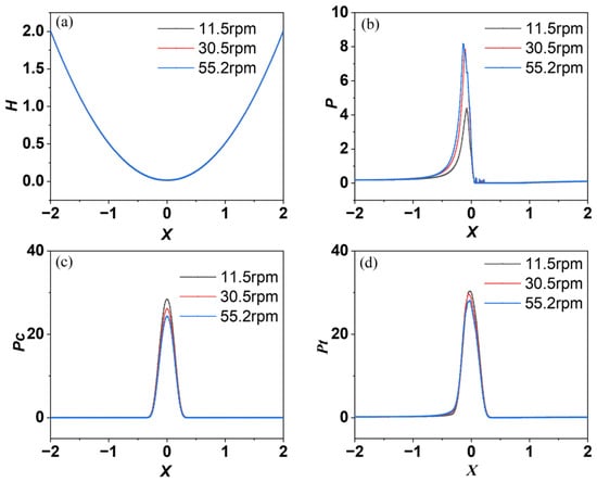
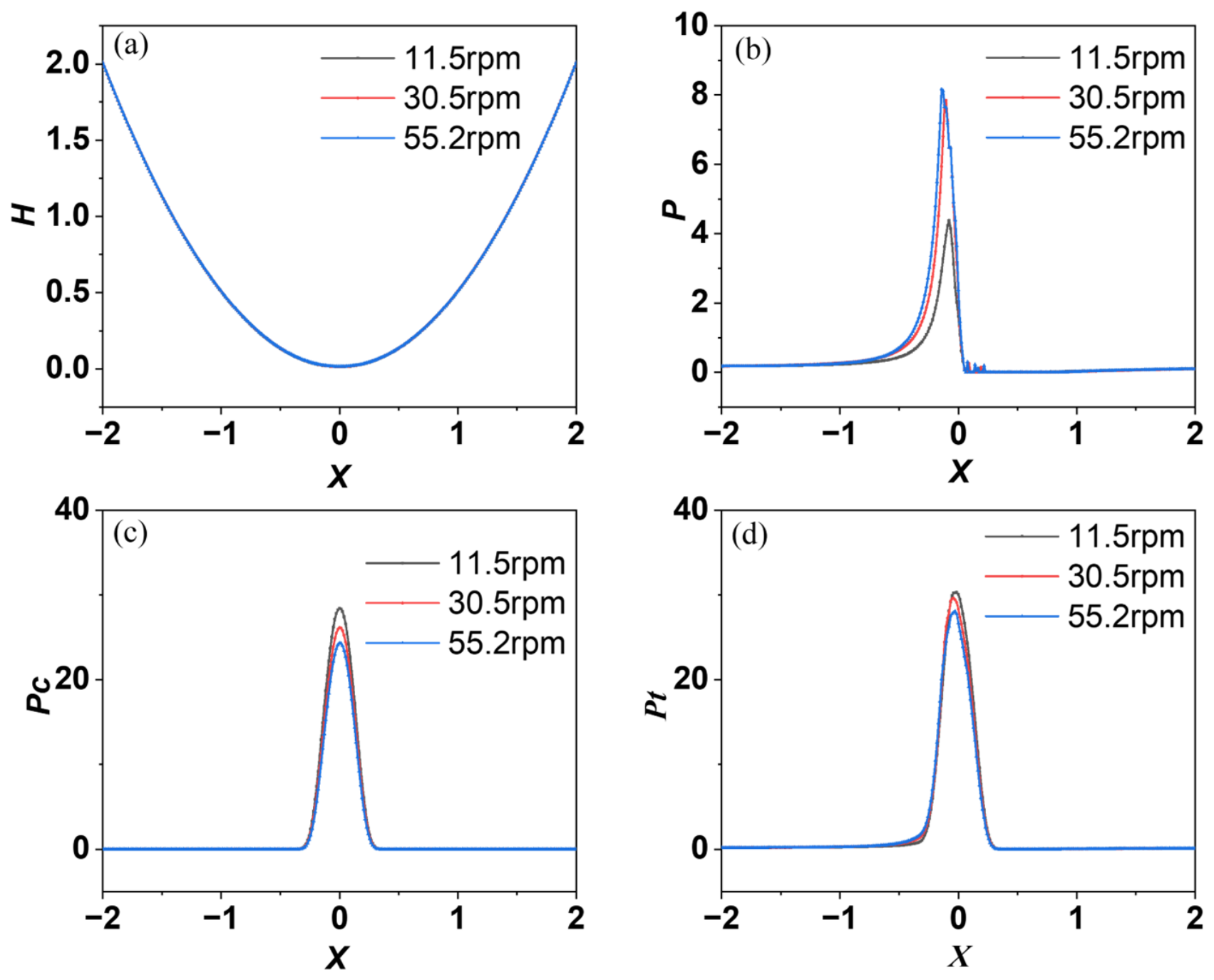
Figure 4 illustrates the influence of different inner shaft rotational speeds on the film thickness and pressure distributions (both axes are dimensionless). The entrainment velocities corresponding to the three rotational speeds are 0.029 m/s, 0.078 m/s, and 0.14 m/s, respectively, all within the low-speed regime. As shown in the figure, the film thickness increases modestly with speed on the plotted dimensionless scale. The fluid pressure increases with increasing rotational speed, whereas the asperity contact pressure exhibits the opposite trend. The total pressure does not show significant variation with rotational speed. No secondary pressure peak and no outlet constriction appear at any speed.
Figure 4.
Effect of speed on (a) grease film thickness, (b) grease pressure, (c) asperity contact pressure, and (d) total pressure along the rolling direction (39.867 N, 300 N preload).
Quantitatively, between 11.5 and 55.2 rpm the minimum dimensionless film thickness increases from 0.01301 to 0.01531. The observed increase in the fluid pressure is balanced by the corresponding decline in the asperity contact pressure (the asperity load ratio declines from 0.765 to 0.619) under an essentially unchanged central total pressure, indicating a redistribution of load from solid asperity contact toward the hydrodynamic film rather than a macroscopic film thickening.
The attenuation of the speed exponent below the classical value has two reinforcing origins. First, the Ostwald power law with n = 0.8 lowers the effective viscosity at the higher shear rates associated with faster entrainment, so that each additional increment of speed generates less hydrodynamic pressure than a Newtonian fluid would. Second, the investigated contacts operate deep in the mixed regime (h/σ = 0.47–1.11): the film growth is constrained by the elastic–plastic contact, which carries the majority of the load at these ultra-low speeds. Both effects together explain why the film thickness responds to speed far more weakly than the classical smooth-surface Newtonian scaling would predict.
The absence of the classical outlet constriction and of the associated secondary pressure spike is a direct consequence of the operating regime. The classical EHL exit features require a full fluid film traversing the contact and an elastic surface responding locally to the fluid pressure gradient at the exit. In the present ultra-low-speed, low-load, rough-surface conditions, the fluid film cavitates shortly after the contact center (X ≈ +0.06), and the outlet region is an unloading ramp of the plastic contact bowl: there is no pressurized fluid at the exit whose pressure gradient could draw a local constriction. The fluid pressure peak forms on the inlet side of the contact (X ≈ −0.09), where the steep rolling wedge concentrates the available hydrodynamic pressure generation, and the film minimum sits at the contact center, pinned by the elastic–plastic contact. The results are consistent with the deterministic mixed-lubrication framework for rough point contacts, in which load is transferred continuously between the fluid film and asperity contact as the film ratio decreases [12].
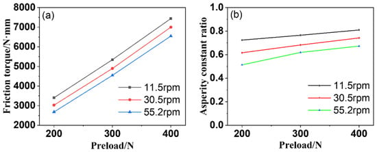
Figure 5 presents the effects of preload and rotational speed on the friction torque and the asperity load ratio. The friction torque is obtained by multiplying the per-contact friction force of Equation (26) by the number of balls and the moment arm r = [(/2 − /2·cosα)2 + (/2·sinα)2]1/2. As can be seen, the friction torque decreases with increasing rotational speed and increases with preload, while the asperity load ratio follows the same trends with speed. Therefore, appropriate adjustment of the preload and an increase in rotational speed are conducive to reducing both the friction torque and the asperity load ratio, thereby improving the lubrication regime and extending the bearing service life.
Figure 5.
Influence of preload and rotational speed on (a) friction torque and (b) asperity load ratio.
The decrease in the friction torque with increasing speed follows directly from the load redistribution described above. The total friction torque comprises a viscous contribution from the sheared lubricant film and a boundary contribution from the direct solid contacts, the latter governed by the boundary friction coefficient 0.2. As the speed increases from 11.5 to 55.2 r/min, the asperity load ratio declines (e.g., from 0.765 to 0.619 at 300 N), so that a growing fraction of the load is carried by the fluid film and the boundary-friction term shrinks accordingly. The viscous term, by contrast, grows only weakly: although the entrainment velocity rises, the film itself thickens only modestly (a factor of 1.18), and the shear-thinning rheology limits the additional shear stress. The reduction in the boundary contribution therefore outweighs the modest viscous increase, and the total torque falls with speed. Physically, faster rotation promotes separation of the mating surfaces, which also supports the operational strategy of raising the speed where the duty cycle allows.
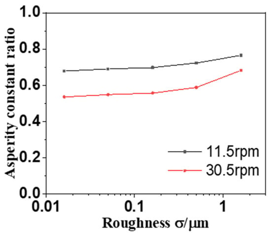
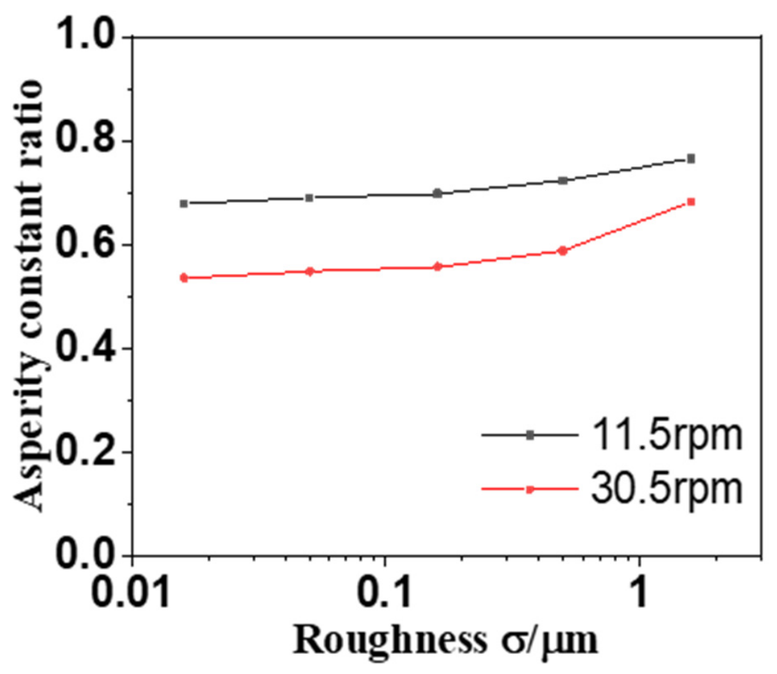
In practical engineering, surface roughness must invariably be considered; thus, lubrication behavior was investigated for surfaces with specified roughness levels. To quantitatively assess the influence of roughness, it was treated as a variable, and the asperity load ratios were analyzed for surface roughness values of 1.6, 0.5, 0.16, 0.05, and 0.016 μm at 11.5 and 30.5 r/min (Figure 6). At 11.5 r/min the asperity load ratio is nearly insensitive to the roughness level (0.765 → 0.679 over two decades of σ): at this ultra-low speed the system lies in the contact-dominated boundary regime, in which the mean film collapses toward zero and the contact carries the load irrespective of the roughness level. At 30.5 r/min, reducing the roughness from 1.6 to 0.5 μm lowers the asperity load ratio from 0.682 to 0.588; a further reduction (σ ≤ 0.16 μm) pushes the balance toward the boundary-regime limit again, with the mean film collapsing to sub-nanometer values and the asperity load ratio leveling off near 0.54. Smoother surfaces therefore lower the asperity load ratio, with the strongest sensitivity at the intermediate roughness levels where the load redistribution between the plastic contact and the hydrodynamic film is most active.
Figure 6.
Influence of surface roughness on the asperity load ratio at 11.5 and 30.5 rpm.
4. Conclusions
In this study, a comprehensive numerical framework was developed for the mixed elastohydrodynamic lubrication (EHL) analysis of rough-surface, grease-lubricated contacts, with its practical utility demonstrated through a space-grade double-row angular contact ball bearing under low-speed operations. The numerical investigations reveal that within the investigated operating envelope, both the rotational speed and axial preload exert a relatively limited impact on the lubricant film thickness. The fluid pressure exhibits a single peak on the inlet side of the contact, and no secondary pressure peak or outlet constriction appears across the investigated operating envelope; the film thickness profile shows a single minimum at the contact center. The asperity load ratio increases with preload and decreases with speed, reflecting the redistribution of load between the plastic contact and the hydrodynamic film.
In terms of tribological performance, the friction torque is found to decrease monotonically with increasing rotational speed and to increase with preload, while the asperity load ratio follows the same trends with speed. This indicates that a carefully calibrated preload coupled with an elevated rotational speed can significantly mitigate both frictional losses and direct asperity interactions. Consequently, optimizing these operating parameters is beneficial for transitioning the contact interface toward a more favorable lubrication regime, thereby extending the operational lifetime of the bearing in demanding space environments.
Finally, the proposed numerical framework successfully unifies the Ostwald rheological model and the Kogut–Etsion (KE) elastoplastic asperity contact model. Owing to its formulation for non-conformal elliptical contacts, the framework is directly applicable to rolling bearings. It thus serves as a versatile and robust computational tool for the lubrication design of advanced space mechanisms and broader industrial applications.
Author Contributions
Conceptualization, Z.X. and M.M.; Methodology, X.Z., M.T., R.X., J.M., L.Z., X.Y., H.L. and Z.X.; Software, X.Z. and Z.X.; Validation, X.Z. and Z.X.; Formal analysis, Z.X.; Investigation, X.Z. and Z.X.; Writing—original draft, X.Z., M.T., R.X., J.M., L.Z., X.Y., H.L., Z.X. and M.M.; Writing—review & editing, Z.L. and Z.X.; Supervision, M.M. All authors have read and agreed to the published version of the manuscript.
Funding
M.M. acknowledges the financial support from MOST (2023YFB4603601) and NSFC (grant no. 12372112) and the support from National Supercomputer Center in Tianjin. Z.X. acknowledges the financial support of China Postdoctoral Science Foundation (grant no. GZC20250942, 2026M791447).
Data Availability Statement
The original contributions presented in this study are included in the article. Further inquiries can be directed to the corresponding author.
Conflicts of Interest
Authors Xiaoming Zong, Renshan Xia, Jiaoyan Ma, Lei Zhang and Xu Yang were employed by the company Jonhon Optronic Technology Co., Ltd. The remaining authors declare that the research was conducted in the absence of any commercial or financial relationships that could be construed as a potential conflict of interest.
References
- Jones, W.R., Jr.; Jansen, M.J. Tribology for Space Applications. Proc. Inst. Mech. Eng. Part J J. Eng. Tribol. 2008, 222, 997–1004. [Google Scholar] [CrossRef] [Scilit]
- Roberts, E.W. Space Tribology: Its Role in Spacecraft Mechanisms. J. Phys. D Appl. Phys. 2012, 45, 503001. [Google Scholar] [CrossRef] [Scilit]
- Wang, Y.; Wang, W.; Li, Y.; Zhao, Z. Lubrication and Thermal Failure Mechanism Analysis in High-Speed Angular Contact Ball Bearing. J. Tribol. 2018, 140, 031503. [Google Scholar] [CrossRef] [Scilit]
- Antoine, J.-F.; Abba, G.; Molinari, A. A New Proposal for Explicit Angle Calculation in Angular Contact Ball Bearing. J. Mech. Des. 2006, 128, 468–478. [Google Scholar] [CrossRef] [Scilit]
- Hu, Y.-Z.; Wang, H.; Wang, W.-Z.; Zhu, D. A Computer Model of Mixed Lubrication in Point Contacts. Tribol. Int. 2001, 34, 65–73. [Google Scholar] [CrossRef] [Scilit]
- Hamrock, B.J.; Dowson, D. Isothermal Elastohydrodynamic Lubrication of Point Contacts: Part I—Theoretical Formulation. J. Lubr. Technol. 1976, 98, 223–229. [Google Scholar] [CrossRef] [Scilit]
- Greenwood, J.A.; Tripp, J.H. The Elastic Contact of Rough Spheres. J. Appl. Mech. 1967, 34, 153–159. [Google Scholar] [CrossRef] [Scilit]
- Chang, W.R.; Etsion, I.; Bogy, D.B. An Elastic-Plastic Model for the Contact of Rough Surfaces. J. Tribol. 1987, 109, 257–263. [Google Scholar] [CrossRef] [Scilit]
- Zhao, Y.W.; Maietta, D.M.; Chang, L. An Asperity Microcontact Model Incorporating the Transition from Elastic Deformation to Fully Plastic Flow. J. Tribol. 2000, 122, 86–93. [Google Scholar] [CrossRef] [Scilit]
- Kogut, L.; Etsion, I. Elastic-Plastic Contact Analysis of a Sphere and a Rigid Flat. J. Appl. Mech. 2002, 69, 657–662. [Google Scholar] [CrossRef] [Scilit]
- Wu, M.; Han, X.; Tao, Y.; Pei, J. A mixed EHL analysis method for grease and formulas for film thickness and asperity load. Tribol. Lett. 2022, 70, 128. [Google Scholar] [CrossRef] [Scilit]
- Hu, Y.-Z.; Zhu, D. A Full Numerical Solution to the Mixed Lubrication in Point Contacts. J. Tribol. 2000, 122, 1–9. [Google Scholar] [CrossRef] [Scilit]
- Wang, Z.; Zheng, P. Numerical study on mixed thermal-elastohydrodynamic lubrication of grease lubricating lubricated spiral bevel gear for heavy-duty unmanned aerial vehicle. Proc. Inst. Mech. Eng. Part J J. Eng. Tribol. 2023, 237, 85–102. [Google Scholar] [CrossRef] [Scilit]
- Li, J.; Zhang, B.; Zhang, Q.; Li, R. The influence of surface topography on mixed plasto-elastohydrodynamic lubrication in point contacts. Proc. Inst. Mech. Eng. Part J J. Eng. Tribol. 2023, 237, 1197–1211. [Google Scholar] [CrossRef] [Scilit]
- Wang, G.; Wang, W.; Zhang, Y.; Shen, J.; Xu, J.; Liu, K. A solution for mixed elastohydrodynamic lubrication modeling considering effects of solid particles and surface roughness. Proc. Inst. Mech. Eng. Part J J. Eng. Tribol. 2022, 236, 2272–2282. [Google Scholar] [CrossRef] [Scilit]
- Shetty, P.; Meijer, R.J.; Osara, J.A.; Lugt, P.M. Measuring film thickness in starved grease-lubricated ball bearings: An improved electrical capacitance method. Tribol. Trans. 2022, 65, 869–879. [Google Scholar] [CrossRef] [Scilit]
- Benois, A.; Echeverri Restrepo, S.; De Laurentis, N.; Hogenberk, F.; Giuntoli, A.; Lugt, P.M. A coarse grained molecular dynamics model for the simulation of lubricating greases. Tribol. Lett. 2024, 72, 78. [Google Scholar] [CrossRef] [Scilit]
- De Laurentis, N.; Kadiric, A.; Lugt, P.M.; Cann, P. The Influence of Bearing Grease Composition on Friction in Rolling/Sliding Concentrated Contacts. Tribol. Int. 2016, 94, 624–632. [Google Scholar] [CrossRef] [Scilit]
- Okal, M.; Kostal, D.; Osara, J.A.; Lugt, P.M.; Krupka, I.; Hartl, M. Experimental study of the effect of thickener on the film thickness in the contacts of a grease-lubricated ball bearing at low speed. Tribol. Trans. 2025, 68, 28–38. [Google Scholar] [CrossRef] [Scilit]
- Rahimpour, M.; Samadani, A.; Akbarzadeh, S. Application of load-sharing concept to mechanical seals. Lubricants 2023, 11, 266. [Google Scholar] [CrossRef] [Scilit]
- Patir, N.; Cheng, H.S. An Average Flow Model for Determining Effects of Three-Dimensional Roughness on Partial Hydrodynamic Lubrication. J. Lubr. Technol. 1978, 100, 12–17. [Google Scholar] [CrossRef] [Scilit]
- Wolff, R.; Kubo, A. A Generalized Non-Newtonian Fluid Model Incorporated into Elastohydrodynamic Lubrication. J. Tribol. 1996, 118, 74–82. [Google Scholar] [CrossRef] [Scilit]
- Masjedi, M.; Khonsari, M.M. Film Thickness and Asperity Load Formulas for Line-Contact Elastohydrodynamic Lubrication With Provision for Surface Roughness. J. Tribol. 2012, 134, 011503. [Google Scholar] [CrossRef] [Scilit]
- Markho, P.H. Highly Accurate Formulas for Rapid Calculation of the Key Geometrical Parameters of Elliptic Hertzian Contacts. J. Tribol. 1987, 109, 640–647. [Google Scholar] [CrossRef] [Scilit]
- Kogut, L.; Etsion, I. A Finite Element Based Elastic-Plastic Model for the Contact of Rough Surfaces. Tribol. Trans. 2003, 46, 383–390. [Google Scholar] [CrossRef] [Scilit]
- Harris, T.A.; Kotzalas, M.N. Rolling Bearing Analysis, 5th ed.; CRC Press: Boca Raton, FL, USA, 2007. [Google Scholar]
- Jones, A.B. A General Theory for Elastically Constrained Ball and Radial Roller Bearings under Arbitrary Load and Speed Conditions. J. Basic Eng. 1960, 82, 309–320. [Google Scholar] [CrossRef] [Scilit]
- Liu, J.; Tang, C.; Wu, H.; Xu, Z.; Wang, L. An Analytical Calculation Method of the Load Distribution and Stiffness of an Angular Contact Ball Bearing. Mech. Mach. Theory 2019, 142, 103597. [Google Scholar] [CrossRef] [Scilit]
- Kingsbury, E. First-Order Ball-Bearing Kinematics. ASLE Trans. 1985, 28, 239–244. [Google Scholar] [CrossRef] [Scilit]
- Harris, T.A. Ball Motion in Thrust-Loaded, Angular Contact Bearings with Coulomb Friction. J. Lubr. Technol. 1971, 93, 32–38. [Google Scholar] [CrossRef] [Scilit]
- Kanazawa, Y.; Sayles, R.S.; Kadiric, A. Film Formation and Friction in Grease Lubricated Rolling-Sliding Non-Conformal Contacts. Tribol. Int. 2017, 109, 505–518. [Google Scholar] [CrossRef] [Scilit]
- Karthikeyan, B.K.; Teodorescu, M.; Rahnejat, H.; Rothberg, S.J. Thermoelastohydrodynamics of Grease-Lubricated Concentrated Point Contacts. Proc. Inst. Mech. Eng. Part C J. Mech. Eng. Sci. 2010, 224, 683–695. [Google Scholar] [CrossRef] [Scilit]

Disclaimer/Publisher’s Note: The statements, opinions and data contained in all publications are solely those of the individual author(s) and contributor(s) and not of MDPI and/or the editor(s). MDPI and/or the editor(s) disclaim responsibility for any injury to people or property resulting from any ideas, methods, instructions or products referred to in the content. |
© 2026 by the authors. Licensee MDPI, Basel, Switzerland. This article is an open access article distributed under the terms and conditions of the Creative Commons Attribution (CC BY) license.