


Abstract
Thermal error remains a primary bottleneck restricting the machining accuracy of precision CNC machine tools. As a proactive, source-level countermeasure, thermal design has become increasingly critical for achieving the accuracy targets required by advanced manufacturing sectors. This paper presents a critical review of machine-level thermal design methodologies, categorizing existing approaches into three principal technical routes: temperature control, material improvement, and structural optimization. For each route, we critically examine the underlying theoretical foundations, representative implementations, and reported effectiveness, with particular emphasis on the persistent gap between academic research and industrial practice. Our analysis reveals that the majority of existing thermal design efforts focus on reducing the magnitude of thermal deformation, while paying limited attention to its spatial distribution. This imbalance, we argue, limits the potential synergies between thermal design and thermal compensation, as spatially complex deformation fields are intrinsically more difficult to model and correct than regular patterns. To address this gap, we propose a paradigm shift from “amplitude minimization” to “deformation mode regularization”: actively shaping the spatial distribution and temporal evolution of thermal deformation to render it more predictable, repeatable, linear, and readily compensable. The review concludes by outlining a forward-looking framework that integrates thermal deformation mode regularization, digital twin-based thermal state perception, and design-for-compensation principles, offering both theoretical foundations and practical guidelines for thermal design in high-precision machine tools.
1. Introduction
CNC machine tools are the cornerstone of advanced manufacturing, and their technological sophistication directly determines the capability and competitiveness of modern industrial production systems. From aerospace structural components and precision optical elements to biomedical implants, the machining accuracy that can be achieved fundamentally constrains the performance and reliability of critical parts in these strategic sectors [1,2].
However, as productivity demands drive ever-higher operating speeds and power densities, a longstanding physical challenge has become increasingly acute: the intensification of internal heat generation [3,4,5]. Internal thermal loads, including electromagnetic losses in spindle motors, frictional heating in bearings and ball-screw pairs, and cutting-zone heat generation, couple with ambient temperature fluctuations to establish a non-uniform, time-varying temperature field within the machine structure. This field induces complex thermo-elastic deformations, such as axial expansion, bending, and warping [6,7,8]. When machining tolerances reach the micrometer or even nanometer scale, thermo-elastic deformation emerges as the predominant accuracy bottleneck. Extensive industrial evidence consistently indicates that thermal error accounts for 40% to 70% of the total error in precision machine tools [9,10,11], and can exceed 75% under ultra-precision conditions [12]. A mere 1 °C variation in ambient temperature can induce machining errors of several micrometers.
To mitigate thermal errors, two complementary technical paradigms have been established. The first is thermal error compensation technology [13,14,15,16,17,18], applied during machine operation, which offsets thermal displacement by injecting corrective commands into the CNC system. The second is thermal design technology [19,20,21,22,23,24,25], which encompasses both design-stage structural interventions (including material selection, geometric configuration, and cooling channel layout) and operational-stage active thermal management, such as real-time cooling regulation and adaptive temperature control.
Thermal compensation has matured into a relatively well-established technical domain, with substantial comprehensive reviews available [14,15,16,17,18,23]. In contrast, the field of machine tool thermal design, despite a growing amount of literature [19,20,21,22,23,24,25], remains comparatively fragmented. Most existing surveys focus narrowly on temperature-control strategies for individual components such as spindles [20,21,25], with limited attention to machine-level integration across temperature control, material innovation, and structural optimization. Furthermore, prior reviews have predominantly adopted a descriptive, technology-cataloging approach, summarizing what has been done, with less emphasis on critically interrogating why certain strategies succeed or fail in practice, or how the resulting thermal deformation interacts with downstream compensation. This review focuses on three aspects that we believe complement existing contributions:
1. A machine-level perspective: Rather than concentrating on individual subsystems (e.g., spindles or feed drives in isolation), we examine thermal design across the entire machine tool, including spindle systems, feed drives, structural foundations, cutting tools, and the ambient environment. This broader scope, we suggest, may help reveal cross-component interactions that are often overlooked in component-specific studies.
2. A problem-oriented critical analysis: We attempt to go beyond cataloging reported performance by discussing methodological limitations, simulation idealizations, and validation gaps that recur across the literature. Particular attention is paid to the persistent disconnect between design intentions and real-world thermal behavior, as this disconnect appears to be a key factor limiting the industrial impact of academic research.
3. A new conceptual lens—deformation mode regularization: We observe that the majority of thermal design studies define success primarily in terms of reducing the amplitude of thermal deformation. The spatial patterns of deformation (how the deformation is distributed across the structure) receive considerably less attention. This observation leads us to propose a complementary perspective: that thermal design might usefully be oriented not only toward minimizing the magnitude of deformation, but also toward shaping its spatial distribution into a predictable, regular form that is more readily modeled and compensated.
The remainder of this paper is organized as follows. Section 2 provides an overview of thermal design methodologies and compares them with thermal compensation. Section 3 and Section 4, and Section 5 review the three principal technical routes, namely, temperature control, material improvement, and structural/parameter optimization, respectively, with a critical commentary on their theoretical contributions and practical limitations. Section 6 synthesizes the persistent challenges and gaps identified across all routes. Section 7 outlines future research directions, with an emphasis on thermal deformation mode analysis, digital twin technology, and design-for-compensation. Section 8 presents the concluding remarks.
2. Overview of Research on Machine Tool Thermal Design
2.1. Scope and Literature Selection
This review adopts a critical review methodology, rather than a systematic review with a prescriptive search protocol. As such, the selection of literature was guided by the authors‘ expertise and informed judgment, with the objective of covering representative and impactful works across the three identified technical routes. The search was conducted in major databases, including Web of Science, Scopus, and Google Scholar et al., covering the period from the 1960s to the present, with an emphasis on peer-reviewed journal articles, conference proceedings, and key research monographs. Given the breadth of the topic and its evolution over six decades, a selective rather than exhaustive approach was necessary.
2.2. Fundamental Connotations of Machine Tool Thermal Design
Machine tool thermal design is a proactive, source-level error control strategy aimed at enhancing the inherent thermal stiffness and accuracy stability of machine structures. Grounded in interdisciplinary theories (including heat transfer, thermo-elastic mechanics, materials science, and mechanical optimization theories), thermal design intervenes at both the design stage and the operational stage. At the design stage, it intervenes by (i) formulating heat management strategies, (ii) developing low-thermal-response materials, and (iii) optimizing structural geometries and assembly parameters to actively regulate temperature-field evolution and thermal deformation behavior. At the operational stage, it encompasses active thermal management measures, such as real-time cooling regulation, adaptive temperature control, and sensor-driven heating strategies, which dynamically respond to changing thermal conditions during machining. This inclusive definition reflects the increasingly blurred boundary between design and operation in modern machine tool thermal management systems. In contrast to the reactive, post-hoc logic of thermal compensation, thermal design follows a preventive paradigm: it seeks to endow machine structures with superior intrinsic thermal performance, achieving multi-objective synergy among thermal stiffness, thermal dynamic behavior, service life, and machining accuracy. Current research on machine tool thermal design encompasses three interconnected levels, as presented below. The content and interrelationships among these three routes are schematically illustrated in Figure 1. It should be noted that the classification of methods into these three principal routes reflects the authors’ critical synthesis of the literature, based on the essential differences in their core mechanisms of thermal error suppression. Consistent with the broad definition adopted in this review, these routes include both design-stage interventions and operational-stage active thermal management measures.
Figure 1.
Three major technical routes of thermal design methods for machine tools.
1. Temperature control. It actively intervenes in heat transfer processes to achieve precise temperature-field regulation. This includes cooling strategies (fluid-medium cooling, phase-change heat transfer elements) and artificial auxiliary heating (active heating to balance temperature fields or generate reverse compensation deformation). Thermal management offers direct and flexible control, but at the cost of increased system energy consumption, structural complexity, and capital expenditure.
2. Material improvement. It transcends the conventional steel-dominated paradigm by selecting or developing novel structural materials with tailored thermophysical properties. Representative examples include low-thermal-expansion alloys, high-thermal-conductivity composites, negative-thermal-expansion materials, and phase-change composites. This route aims to fundamentally alter the intrinsic thermal response of the structure.
3. Structure and parameter optimization. It shapes the thermal response characteristics at the hardware level by modifying geometric configurations, adjusting design parameters, or optimizing structural layouts. Rather than directly controlling temperature or replacing materials, this approach optimizes the structural form so that it inherently resists thermal deformation or channels it towards non-critical directions.
2.3. Comparative Analysis: Thermal Design Versus Thermal Compensation
As the two dominant technical paradigms for reducing thermal error, thermal design and thermal compensation are often discussed as complementary approaches. Ideally, they would form a synergistic system in which preventive design and corrective compensation reinforce each other. In practice, however, they have largely evolved as independent research tracks, with limited cross-fertilization. Thermal design researchers typically concentrate on design-stage optimization but seldom consider the implementation requirements of compensation models; conversely, thermal compensation researchers generally accept the as-built thermal characteristics of existing structures as given, without exploiting the advantages afforded by deliberate thermal design. This separation has practical consequences. Thermal design can reduce heat generation at the source, balance the temperature field, and, in principle, help to regularize thermal deformation into predictable, regular spatial modes that are more amenable to compensation. Thermal compensation can then address residual errors that cannot be eliminated through design alone. Viewed from this perspective, a more effective error-control strategy would position thermal design as the foundation and thermal compensation as the supplement, treating them not as alternatives but as complementary elements of an integrated accuracy-assurance system. From a techno-economic perspective, thermal design typically involves higher upfront investment in research, prototyping, and validation, with benefits that accrue over the machine‘s lifecycle. Thermal compensation generally requires lower initial expenditure but entails ongoing costs for sensors, model maintenance, and periodic recalibration. These two paradigms are suited to different accuracy requirements and application scenarios. A comprehensive comparison is summarized in Table 1.
Table 1.
Comparison of technical characteristics between thermal design and thermal compensation of machine tools.
It should be noted that the comparisons above represent general tendencies under typical assumptions rather than universal properties. Actual performance of both thermal design and thermal compensation depends critically on implementation quality, operating conditions, and maintenance practices. A poorly designed cooling system may exhibit low robustness, while a well-implemented adaptive compensation system may perform robustly across its intended operating envelope. The table is intended to highlight the conceptual and operational differences between the two paradigms, not to assert the inherent superiority of one over the other.
2.4. Development History of Thermal Design for Machine Tools
The review begins in the 1960s, as this period marks the earliest systematic investigations of thermal behavior in machine tools at the machine level. Earlier foundational work on individual components and general heat transfer principles exists, but the recognition of thermal error as a distinct machine-level accuracy bottleneck, and the first targeted countermeasures, emerged during this decade. Notably, Bryan’s 1967 keynote report at the CIRP General Assembly [26] first brought international attention to thermal error as a primary limitation on machining accuracy, and Spur, De Haas systematic investigations of thermal behavior in NC machine tools [9] established the empirical and analytical foundations for subsequent research. Since then, driven by parallel advances in computational methods, materials science, and intelligent control, machine tool thermal design has undergone a paradigm evolution: from passive response to proactive prevention, from component-level optimization to machine-level system integration, and from empirical trial-and-error to science-based, digitally enabled design. We identify four distinct developmental stages:
Stage 1, the embryonic stage (1960s to the 1980s), was concerned with problem identification and initial exploration. This period was characterized by recognition of thermal issues as a primary accuracy bottleneck and the first tentative countermeasures. In 1967, Bryan delivered a keynote report at the CIRP General Assembly, summarizing the international state of thermal error research [26]. In the 1970s, Spur, De Haas [9] systematically investigated the thermal behavior of CNC machine tools and proposed passive heat dissipation strategies. In 1976, Sata et al. [5] pioneered the concept of active control based on heat-source compensation. In 1979, Sada et al. [27] introduced the concept of thermal stiffness, establishing it alongside static and dynamic stiffness as key quantitative performance indicators for machine structures; Kuznetsov and Koriath [28] further emphasized its importance afterwards. Entering the 1980s, composite materials and zero-thermal-expansion materials began to be explored for spindle applications [29,30].
Stage 2, the foundation stage (1990s to the 2000s), was marked by theoretical and methodological consolidation. This period saw the progressive establishment of theoretical frameworks and analytical methodologies. The advent of finite element analysis (FEA) and numerical simulation shifted thermal design from qualitative reasoning to quantitative analysis. In 1990, Bryan [11] reaffirmed that thermal deformation remained the single largest contributor to dimensional error, and identified three solution pathways: (i) blocking heat sources, (ii) implementing thermally symmetric structures, and (iii) real-time software compensation. In 1995, Weck et al. [13] elaborated on these technical routes, emphasizing the central roles of thermal modal analysis (referred to as time-domain modes), active cooling, and thermal balance design. In 1999, Bossmanns and Tu [31] established a thermo–mechanical coupled thermal model for motorized spindles, which became a foundational reference for subsequent spindle thermal research.
Stage 3, the rapid development stage (2000s to the 2020s), was characterized by concurrent breakthroughs across multiple routes. This period witnessed parallel advances across all three technical pathways. In 2012, Mayr et al. [12] published a landmark CIRP keynote paper covering thermal error measurement, numerical modeling, and error suppression strategies. The widespread adoption of computational fluid dynamics (CFD) and thermal–fluid–solid coupling simulation established computer-aided thermal analysis as the dominant research paradigm. Notably, from 2011 to 2023, Germany’s DFG-funded Collaborative Research Center TRR 96 (“Thermo-Energy Design of Machine Tools”) operated as the most systematic and comprehensive research program in the field, spanning modeling, simulation, measurement, compensation, and design across the entire machine lifecycle [32,33,34].
Stage 4, the ongoing advancement stage (2020s to the present), was dedicated to intelligentization, synergy, and green transition. The current stage is distinguished by a trajectory towards intelligent thermal management, system-level collaborative optimization, and sustainable manufacturing [35]. Digital twin technology, artificial intelligence, advanced heat pipe thermal management, topology optimization (TO), and multi-physics coupling simulation are being integrated into an emergent structure–material–thermal control–algorithm co-design paradigm. Machine-level thermal collaboration and digital-twin-based robust error suppression are now prominent research frontiers. The historical evolution of machine tool thermal design is schematically illustrated in Figure 2.
Figure 2.
Schematic diagram of the historical evolution of thermal design research for machine tools.
3. Temperature-Control-Based Thermal Design for Machine Tools
Temperature-control-based thermal design achieves precise control of the machine tool temperature field by actively intervening in the heat transfer process. This category is mainly divided into two types. The first is the cooling method, which removes heat from heat source regions via fluid media (water, oil, air) or phase-change heat transfer elements (heat pipes, thermosyphons, etc.). Cooling is the most direct temperature control measure in machine tool thermal design. The second is the artificial auxiliary heat source method, which actively heats low-temperature regions of the structure to achieve temperature field equalization or actively generate reverse deformation. This section systematically reviews the research progress of temperature-control-based thermal design from five levels: spindle systems, feed systems, basic large components, tools and cutting space, and ambient conditions of machine tool.
3.1. Temperature Control Design for Spindle Systems
The spindle system concentrates multiple internal heat sources, such as bearings, motors, and in some cases cutting-zone heat, and is therefore a primary contributor to thermal error in machine tools. Accordingly, temperature-control-based thermal design for spindle systems has received more research attention than any other subsystem. This section reviews four main cooling strategies: spindle sleeve cooling, shaft core cooling, motor cooling, and bearing cooling.
3.1.1. Temperature Control Design of Spindle Sleeve
Spindle sleeve cooling is the most widely adopted temperature-control measure in machine tool thermal design. By routing circulating coolant through channels integrated into the housing, this approach extracts heat conducted from the stator, bearings, and other internal components. Despite its apparent simplicity, cooling channel design involves a complex trade-off among heat dissipation capacity, temperature uniformity, pressure drop, and manufacturability, a balance that has motivated extensive research over the past two decades.
Early studies focused predominantly on spiral cooling channels owing to their manufacturing simplicity and effective circumferential heat coverage. Chien, Jang [36] developed a 3D conjugate heat transfer model for a high-speed spindle with a helical water-cooling channel, validated it experimentally, and proposed a Nusselt number correlation for enhanced thermal design. However, the model neglects natural convection and radiation, assumes constant fluid properties and uniform heat distribution, and the correlation is limited to a specific rectangular helical channel geometry, restricting broader applicability. Chen et al. [37] identified a critical coolant flow rate beyond which further flow fails to suppress temperature rise and confirmed that ambient temperature has negligible effect. Huang et al. [38] revealed the superiority of reciprocating cooling channels over single/double spiral channels, utilizing the low-temperature zone of the spindle for “graded cooling” and making thermal displacement mainly manifest as axial elongation. However, the steady-state model neglects thermal radiation, viscous dissipation, and bearing dynamics, and shows noticeable quantitative deviations from experiments. Bao et al. [39] optimized the annular cooling groove into a zoned spiral groove structure, achieving a 12.7% reduction in the maximum temperature rise. However, their model neglects contact resistance, transient effects, and internal validation, and relies on small-sample empirical data. Weber et al. [40] innovatively compared three common cooling-sleeve designs via CFD–CHT, quantified energy-flow distribution, and revealed that wall roughness up to 100–200 µm can more than double the heat transfer coefficient, with the greatest gain in the double-helix layout. However, the steady-state model neglects buoyancy and uses constant properties except viscosity, limiting practical applicability. Lei et al. [41,42,43,44,45] proposed an external helical-tube cooling scheme with a silicone-grease-coated cambered-flat interface thermal resistance model, and constructed the “active cooling-spindle” system as a thermal error feedback control loop employing data-driven and physical-based ensemble models with V-C dimension generalization error bound estimation to stabilize spindle thermal error long term. However, they rely on empirical quasi-static bearing heat generation and convective coefficients, temperature measurements are severely disturbed by varying coolant temperature, and validation is limited to a single mechanical spindle without fully addressing ambient disturbances, energy consumption, and long-term closed-loop robustness.
To overcome the limitation of uneven axial temperature distribution of spiral channels, researchers have explored various channel configurations. Mansingh, Pravin [46] developed a 3D CFD model of a high-speed spindle housing with an axial rectangular cooling channel, showing that increasing loop counts from 6 to 10 substantially lowers outer wall temperature under varied heat sources. However, the steady-state model assumes constant fluid properties and isotropic thermal conductivity, simplifies heat sources as fixed wall temperatures without coupling motor heat generation, and relies on the empirical Dittus–Boelter equation for convective heat transfer. Li et al. [47,48,49,50] combine multi-physics simulation with experimental validation for the A02 high-speed motorized spindle, proposing an external capillary copper tube with thermally conductive silica gel, identifying an optimal coolant flow rate, designing serpentine and response-surface-optimized water jackets with additional front/rear bearing channels, and developing a novel jacket that reduces temperature by up to 32.11% and spindle thermal displacement by 32.63%. However, they share steady-state assumptions, empirically prescribed heat sources and convective coefficients, shell-only temperature measurement without internal validation, lack of transient thermal inertia and variable-speed/load verification, and no consideration of pump power consumption or closed-loop control, limiting generalizability beyond the specific A02 spindle. Zhang et al. [51] built a thermal–fluid–structure coupled model and proposed a U-shaped cooling jacket that lowers temperature and radial deformation versus the spiral design. However, the model neglects transient thermal inertia, internal sensor validation, and pump-power trade-offs. Zhang et al. [52] designed and compared spiral and U-shaped cooling systems for a grinding motorized spindle via ANSYS Fluent simulation and experiments, confirming the U-shaped system’s superiority in temperature control, vibration reduction, and rotational accuracy. However, their model relies on empirically partitioned heat sources, assumes constant fluid properties, and lacks internal-temperature measurement, variable-load grinding validation, and pump-power/energy consumption analysis. Dai et al. [53] studied T-shaped cooling channels and determined the optimal parameters as an inlet temperature of 20 °C and a flow rate of 8 L/min. However, their model relies on empirically calculated heat sources, assumes constant properties, lacks internal-temperature measurement, and provides no pump-power or energy consumption analysis. Koch et al. [54] proposed a three-pillar evaluation concept (effectiveness, efficiency, and thermal asymmetry) to compare helix, meander, and S-meander stator cooling sleeves via coupled thermal/fluid-mechanical simulation, reducing average stator temperature by 2.3 K through pure geometrical optimization (Figure 3). However, their concept relies on empirically determined heat sources and surface-only PT-100 validation without internal temperature measurement, and lacks pump-power/energy consumption analysis. Li et al. [55] compared four channel types and optimized dimensions to reduce bearing temperature by 6.7 °C and deformation from 53.8 μm to 30.9 μm. These studies have demonstrated the feasibility of geometric optimization for improved temperature uniformity. Nevertheless, most of these investigations were conducted under steady-state thermal assumptions and did not account for the transient thermal behavior that dominates actual machining cycles.
Figure 3.
A comparison of helix, meander, and S-meander stator cooling sleeves via coupled thermal/fluid-mechanical simulation [54].
To improve cooling performance, researchers have also carried out bionic and topology-optimized channel designs. Xia et al. [56] designed a cylindrical fractal tree cooling sleeve for spindles, established conjugate heat transfer models, and validated its superior cooling performance via physical tests, yet it only covered laminar flow conditions and fails to consider the actual uneven heat distribution of real motorized spindles. Ma et al. [57] developed an OpenFOAM FVM thermal–fluid topology optimizer integrated with AMR and parallel computing for motorized spindle cooling jackets, slashing memory usage by 82.6% and spindle thermal error by 25.5%. However, the optimizer adopted a simplified Darcy flow surrogate instead of native RANS turbulence TO, lacking multi-physics structural coupling analysis for spindle assemblies. Li et al. [58,59] designed a calibrated lightweight Darcy multi-objective TO model for spindle jackets, drastically cutting computation time while balancing temperature and pressure loss, and validated optimized channels against spiral/serpentine ones via multi-physics RANS simulation. However, the model lacked physical prototype tests; irregular optimized channels bring machining difficulties, and the Darcy model still needs repeated RANS calibration to offset inherent flow simulation errors.
To further enhance heat transfer efficiency, Donmez et al. [60] adopted slitted Coanda silicone tubing for low-cost spindle air cooling and achieved 36% thermal drift reduction. However, the study only tested a single lathe spindle and lacked universal multi-machine and heavy-load experimental verification. Bae et al. [61] proposed two trapezoidal vortex generators for in-wheel motor channels and quantified cooling gains under ram air via CFD. However, they relied only on numerical simulation without physical prototype tests and ignored variable coolant flow rates and real vehicle complex road working conditions. Tang et al. [62] proposed four convex protrusions inside spindle channels to boost vortex heat transfer and identified optimal triangular prism layout via CFD. However, they only relied on single-flow-rate numerical simulations without physical prototype tests and ignored pressure loss and actual spindle speed variations. Li et al. [63] adopted field synergy theory to optimize three convex column shapes and parameters for spindle cooling channels (Figure 4). However, they only relied on static CFD simulations without physical prototype tests and ignored variable spindle speeds and actual pump power consumption analysis. Ma et al. [64] embedded a novel CLTPPHP into vertical spindle jackets and optimized its performance via RSM and real machining tests. However, the study lacked long-term durability tests and multi-speed spindle working condition validations.
Figure 4.
Triangular prism structures based on the field synergy principle [63].
Koreta et al. [65] conducted early exploration of electronic cooling based on the Peltier effect. Fan et al. [66,67] proposed a PID-controlled TEC cooling sleeve with optimized contact areas to homogenize spindle temperature and cut thermal errors drastically. However, the study overlooked long-duration high-load machining tests, omitted coolant condensation risk analysis, lacked multi-type spindle adaptability verification, and failed to explore energy consumption and service life of thermoelectric chips. While thermoelectric cooling provides bidirectional thermal control (both cooling and heating) and fast response, its coefficient of performance remains low, and the heat rejection from the hot side requires secondary cooling, factors that limit its application in high-power spindles.
Driven by refined thermal control demands, spindle cooling technology is gradually developing towards intelligence and high efficiency. Shabi et al. [68] quantified that fluid systems account for 44–51% of total energy consumption and pointed out the mismatch between cooling supply and actual thermal demand. Weber et al. [69,70,71,72] integrated CFD parametric analysis and lumped thermo-hydraulic network models, proposed decentralized cooling architectures with component-specific flow control and validated them via machine tests to cut energy use and homogenize temperature fields. However, the study only tested a single five-axis machine, overlooked variable cutting load coupling, omitted long-duration machining endurance tests, lacked multi-spindle type adaptability research, and failed to optimize the trade-off between cooling performance and pump power loss thoroughly. Grama et al. [73] proposed a Cooler Trigger Model (CTM) cooling control that matches actual spindle heat and substantially cuts thermal errors. However, the study overlooked ambient disturbance compensation and lacked heavy-load machining verification. Liu et al. [74,75] built multi-loop differentiated cooling hardware and real-time power matching control to synchronize spindle heat generation and dissipation, substantially stabilizing temperature and cutting thermal errors. However, the study only tested fixed constant ambient conditions and overlooked variable workshop temperature interference and heavy cutting load coupling effects. Zhang et al. [76,77,78] proposed a PID-BPNN active coolant strategy balancing spindle internal heat and time-varying ambient convection, stabilizing temperature and cutting thermal errors significantly. However, the approach was only validated under a fixed coolant flow rate and on a single spindle prototype and overlooked variable coolant power consumption, long-duration fatigue tests, and multi-type spindle adaptability verification under diverse complex machining loads. Li et al. [79,80] proposed variable oil flow and temperature adaptive cooling using a regression model to cut spindle thermal deformation and shorten warm-up time. However, the study only tested a single spindle type without a heavy cutting load or long-duration endurance validation. Li et al. [81] built a cubic regression adaptive oil–gas cooling control for geared spindles and cut multi-axis thermal deformations substantially. However, the study only tested limited speed ranges without a heavy cutting load or long-time continuous operation validation. Mori et al. [82] proposed an on-off cooling strategy running at high-COP sweet spots and supporting pump shutdown to cut cooling power significantly. However, the strategy produced unavoidable thermal displacement fluctuations and lacked self-adaptive interval adjustment for variable heavy cutting loads. Reibert et al. [83] combined mycelium insulation and ANN-based MPC multi-circuit cooling to stabilize spindle thermal field and cut thermal errors. However, the study only tested a single spindle rig without full machine deployment or energy consumption optimization validation. Chiang et al. [84] integrated a Smith predictor with PID for hot-gas-bypass oil coolers to achieve 0.1 °C precise temperature control. While these intelligent control strategies demonstrate considerable potential, their robustness in complex industrial environments (where sensor drift, actuator aging, and sudden changes in operating conditions are common) requires further validation.
3.1.2. Thermal Design of Spindle Shaft Core Temperature Control
The spindle shaft core, particularly the front-bearing inner ring and rotor region, is the primary heat source and the direct origin of axial thermal elongation. Traditional external housing cooling cannot directly reach these rotating components. Direct cooling of the shaft core has therefore been a challenging but active area of research.
Heat pipe and thermosyphon-based cooling is a representative technology for efficient heat dissipation via phase-change heat transfer. Judd et al. [85] embedded heat pipes inside the hollow spindle of a milling machine, reducing steady-state temperature rise of bearings by approximately 50%. Luo et al. [86,87] designed an Axial Rotating Heat Pipe (ARHP) suitable for high-speed spindles, reducing maximum temperature by 50% and thermal deformation by 76.5%. Ma et al. [88] proposed integrating Grooved Heat Pipes (GHPs) into the spindle axis, significantly reducing temperature rise and thermal error. Zhou et al. [89] designed a sintered wick heat pipe suitable for rotating conditions and verified its effectiveness in reducing temperature rise and thermal deformation. Liu et al. [90] proposed a digital twin model of rotating sintered heat pipes based on Simulink, combining PINN, Transformer, and LightGBM models for thermal prediction with errors below 0.85 °C. Li et al. [91,92,93] designed a shaft cooling structure based on an R600a two-phase loop thermosyphon (TPLTS), reducing the maximum temperature rise of the spindle by 44%. Liang et al. [94,95,96] proposed a “squirrel-cage” central cooling structure based on micro rotating vapor heat pipes (MRVHPs), reducing maximum spindle temperature by 35%. Shi et al. [97] established a two-dimensional numerical model for loop rotating heat pipes (RHPs) using the Volume of Fluid (VOF) method combined with the Lee phase change model. However, RHPs face several distinctive challenges. The complex gas–liquid two-phase flow and heat transfer mechanisms under rotating conditions, particularly the influence of centrifugal force and Coriolis force, are not yet fully characterized. Integration with rotating components involves complex dynamic sealing, dynamic balancing, and structural stiffness issues. Most studies remain at the simulation and laboratory verification stage, with few engineering applications reported. The long-term reliability of heat pipes under continuous high-speed rotation, including potential wick degradation and sealing failure, has not been systematically investigated.
3.1.3. Thermal Design of Spindle Motor Temperature Control
In built-in motor spindles, electromagnetic losses from the stator and rotor constitute one of the largest heat sources. Since the motor is located in the enclosed space inside the spindle and the rotor rotates at high speed, heat dissipation conditions are severe, making motor temperature control a core challenge.
Stator cooling has been the primary focus of motor thermal management. The traditional approach, a spiral water jacket on the outer housing, has been extended through various improvements. Groll et al. [98] developed copper–water heat pipes for asynchronous traction motors, transferring approximately 75% of motor-dissipated heat. Le et al. [99] combined embedded flat heat pipes with water-cooled housing for yokeless and segmented armature axial flux motors. Chang et al. [100] designed air-cooling and water-cooling schemes for stator core and windings. Wu et al. [101] designed an embedded cold water-cooling structure with direct contact to stator teeth, reducing armature and excitation winding temperature rises by factors of 4.1 and 3.6, respectively. Yu et al. [102] designed axial Z-shaped liquid cooling channels and used high-thermal-conductivity aluminum rings to improve heat conduction. Zhang et al. [103] proposed a composite thermal management scheme combining oil-immersed cooling with in-slot channel cooling. Hyeon et al. [104] proposed installing deflectors for winding ends of air-cooled motors. Wang et al. [105] established a three-dimensional fluid–solid coupled heat transfer model for a 560 kW gas–liquid cooled motor. Ge et al. [106] integrated a lumped-parameter thermal network and CFD to optimize channel number and structural form. Tüysüz et al. [107,108] proposed five forced cooling schemes for ultra-high-speed motors and developed an integrated annular gap cooling structure reducing hot-spot temperature by more than 20 °C.
Rotor cooling has always been a difficult point in motor thermal design. Zhu et al. [109] designed an axial–radial hybrid ventilation structure inside the rotor, reducing maximum temperature rise by 26.5 K. Qi et al. [110] investigated the influence of spiral channel turns and flow rate on motor component temperature rise. Cao et al. [111] proposed a variable-section axial ventilation hole structure to regulate air flow velocity. Zhang et al. [112] designed a direct oil cooling topology with rectangular oil ducts. Ismagilov et al. [113] proposed a combined cooling system using air-gap windings as heat sinks. These studies demonstrate that rotor cooling is feasible but typically involves complex structural modifications that may affect dynamic balance and mechanical strength.
Hybrid cooling and system-level thermal management have gained increasing attention. Ponnappan, Leland [114] designed the rotor shaft itself as an RHP. Sun et al. [115] proposed a composite thermal management strategy combining three-dimensional heat pipes and potting silica gel. Fang et al. [116] proposed a thermal management scheme based on three-dimensional heat pipes for motor housings. Kral et al. [117] proposed an axial–radial two-dimensional thermal network model based on Modelica. Farsane et al. [118] used infrared thermal imaging, laser tomography, and laser Doppler velocimetry to propose thermal design improvements. Putra et al. [119] proposed a motor thermal management system based on L-shaped flat heat pipes. Li [120] established a full three-dimensional conjugate heat transfer numerical model for permanent magnet motors with centrifugal impellers. Kim et al. [121] installed auxiliary air-gap fans, improving winding cooling performance by 55% on average. Karashima et al. [122] proposed a multi-physics coupled transient thermal analysis method. Huang et al. [123] proposed a hybrid cooling system combining heat pipes and liquid cooling. Sasa et al. [124] studied a 1 kW-class superconducting motor cooled by subcooled liquid nitrogen. Han et al. [125] investigated oil churning influence on direct oil injection cooling performance. These hybrid approaches offer improved heat dissipation but at the cost of increased system integration complexity, stricter sealing requirements, and higher manufacturing costs.
3.1.4. Thermal Design of Spindle Bearing Temperature Control
The temperature rise of spindle bearings, as localized heat sources, directly affects bearing life and spindle positioning accuracy. Bearing cooling research has focused primarily on lubrication cooling and external auxiliary cooling.
Oil–air lubrication has become the mainstream choice for high-speed spindles due to its good lubrication and heat dissipation performance. Jiang, Mao [126] systematically investigated the influence of oil–air lubrication parameters on bearing temperature rise. Yan et al. [127] compared outer-ring and side-injection lubrication modes through numerical simulation and experiments. These studies have established parametric guidelines for oil–air lubrication, yet the optimal parameter combination depends on operating conditions, and dynamic adjustment strategies, rather than fixed settings, may be necessary for variable-speed applications.
Localized cooling and enhanced heat conduction offer more targeted thermal management. Morimura et al. [128,129] proposed a local precise temperature control technology for the front-bearing inner ring by integrating composite spiral channels and deep inclined grooves inside the rotating spindle with a multi-cavity labyrinth gas seal structure (Figure 5a). This approach concentrates cooling exactly where it is most needed, at the front bearing, and represents a shift from uniform cooling to targeted cooling. The complexity of the spindle structure, however, makes such designs challenging to manufacture and maintain. Li et al. [130] proposed constructing radial heat conduction paths filled with high-thermal-conductivity copper between the bearing housing and casing (Figure 5b), and further performed TO on the radial heat conduction holes [131]. This passive approach, improving heat conduction rather than enhancing convection, offers the advantage of simplicity and reliability, but the performance gain is limited by the available cross-sectional area and the thermal conductivity of the filler material. Liu et al. [132] proposed an active cooling control strategy based on thermal simulation inference using the Extreme Learning Machine (ELM) algorithm.
Figure 5.
Cooling of Spindle Bearing: (a) Temperature control design for spindle front bearing with multi-cavity labyrinth gas seal structure [128]; (b) Optimization of radial heat conduction paths filled with high-thermal-conductivity copper [130].
The heat-generation mechanism of bearings is complex, being affected by rotational speed, load, lubrication state, and preload in a coupled manner. Cooling structure design must coordinate with stiffness and sealing requirements. The optimal matching of oil–air lubrication parameters requires dynamic adjustment according to specific working conditions, a capability that has been demonstrated in research but not yet widely implemented in industrial practice. A summary of thermal design methods for spindle systems is presented in Table 2.
Table 2.
Summary of thermal design methods for spindle system of machine tools.
3.2. Temperature Control Design for Feed Systems
Thermal error in feed systems originates primarily from frictional heat generation in ball screw–nut pairs, support bearings, guideway sliders, and drive motors. These heat sources induce thermal elongation and thermal bending of the lead screw, directly impairing positioning accuracy. Temperature-control-based thermal design for feed systems has been developed mainly around lead screws, moving nuts, bearings, and guideways.
3.2.1. Temperature Control Design for the Lead Screw Shaft Core
The lead screw shaft is the primary structural element of the feed system, and its thermal elongation is a major contributor to positioning error. Cooling strategies for the shaft core have followed two main approaches: forced cooling through hollow shafts and passive cooling via built-in heat pipes.
Forced cooling of hollow ball screws has been extensively investigated. Xu et al. [133] proposed a built-in air-cooling system and systematically investigated the suppression effect of liquid cooling media on thermal deformation [134], finding that forced water cooling achieves the fastest temperature equilibrium and the greatest reduction in thermal deformation. They further proposed a novel air-cooling system for nuts and lead screws [135]. While forced cooling is effective, it introduces practical challenges: hollow screws have reduced torsional and bending stiffness compared with solid counterparts, and the coolant itself warms as it travels along the screw length, creating axial temperature gradients that may induce bending moments, an effect that is often overlooked in studies that report only overall temperature reduction.
Built-in heat pipes offer a passive alternative. Hu, Ding [136] introduced heat pipe technology into ball screws and designed a novel lead screw with built-in heat pipes, achieving a surface temperature gradient below 1.5 °C under a single-heat-source condition. This passive approach is appealing because it requires no external energy input or complex fluid connections. However, the integration of heat pipes into lead screws raises questions about long-term reliability under cyclic loading and the effectiveness of heat pipes in applications where the heat source moves along the screw length rather than remaining stationary.
Active temperature control strategies have been proposed to address the limitations of passive and fixed cooling. Liu et al. [137] proposed an active coolant control strategy for precision ball screw units that outperforms the traditional ambient temperature tracking method. Zheng et al. [138] proposed an active temperature control method based on the time grating principle, and further proposed a thermal–stiffness coupled transient modeling method with particle swarm optimization (PSO) [139]. Wu et al. [140] analyzed heat source contribution and allocated cooling resources via PSO to minimize thermal deformation. These active strategies demonstrate the potential of model-based control for feed system thermal management. Their effectiveness, however, depends on accurate thermal models and reliable sensor inputs, both of which are subject to uncertainties in real production environments. The robustness of these control strategies under variable cutting conditions and in the presence of sensor drift has not been thoroughly evaluated.
3.2.2. Temperature Control Design for Moving Nuts and Feed Sliders
The moving nut is another major heat source in ball screw feed systems. Direct cooling of the nut, however, poses considerable challenges: the nut moves along the screw, making fluid connections difficult, and the heat source itself is in motion, complicating heat extraction. Ma et al. [141] proposed an innovative strategy of directly cooling the moving nut using multi-objective TO and 3D printing. They further proposed a novel thermal error control strategy using sintered core heat pipes (SCHPs) integrated into the nut cooling jacket, reducing positioning error by 74.8–88.7% [142]. Zeng et al. [143] integrated fractal theory and TO to design optimized flow channels for direct cooling of moving heat sources. While these studies demonstrate that direct cooling of moving nuts is feasible, several practical concerns remain. AM is currently the primary fabrication method for topology-optimized nut cooling channels, a process that remains costly and is not yet scalable for mass production. The dynamic sealing of fluid connections to a moving component, as required for active liquid cooling, has not been demonstrated over extended service life. Heat-pipe-based solutions, while avoiding fluid connections, require reliable operation under reciprocating motion, a condition that may accelerate wick degradation or cause vapor flow disruption. System-level thermal coupling (how nut cooling affects screw temperature distribution and overall feed system accuracy) has not been fully analyzed in the reviewed studies.
3.2.3. Temperature Control Design for Lead Screw Bearings and Feed Guideways
While hollow screw shaft cooling and moving nut cooling address the primary heat sources along the feed drive axis, the support bearings at the fixed or supported ends of the ball screw and the guideway sliders that constrain the moving table constitute additional, localized heat sources that can induce significant thermal errors. Unlike the screw shaft, which undergoes predominantly axial thermal elongation, bearing and guideway heat generation manifests as localized thermal gradients that induce tilting, misalignment, and nonlinear friction variations, effects that are particularly detrimental to positioning accuracy and trajectory fidelity. However, compared with the extensive literature on screw shaft cooling, research dedicated to bearing and guideway temperature control remains relatively sparse and fragmented. Shi et al. [144] established heat generation and forced convection models for lead screw support bearings and designed a valve-controlled flow regulation system based on fuzzy PID, achieving a temperature drop of approximately 3 °C. Uhlmann et al. [145,146] developed an adaptive cooling system integrated with TECs for linear direct drives, adopting a primary–secondary dual heat path design that reduced heat source temperature by 24.6% and global thermal resistance by 38.1% (Figure 6). The primary limitation of bearing cooling, however, is the difficulty of cooling floating-end bearings, where fluid connections are impractical. Valve-controlled systems have limited response bandwidth and are constrained by mechanical lag. TEC-based guideway cooling offers precise temperature control but at the cost of high energy consumption and system complexity. The summary of thermal design methods for ball screw feed drive system of machine tools is presented in Table 3.
Figure 6.
Adaptive cooling system for feed guideways integrated with TECs [145]: (a) Concept to integrate thermoelectric generators in a feed unit of a machine tool with LDD; (b) Prototypically realized thermoelectric self-cooling system as a test bench for collecting experimental data.
Table 3.
Summary of thermal design methods for ball screw feed drive system of machine tools.
3.3. Thermal Balance Design of Basic Large Machine Tool Components
Basic large components (bed, column, spindle headstock, crossbeam, etc.) constitute the structural skeleton of a machine tool. Their temperature field distribution and thermal deformation directly determine the geometric accuracy and spatial error of the entire machine. Thermal design for these components encompasses not only cooling but also, increasingly, the use of artificial auxiliary heat sources to achieve thermal balance.
3.3.1. Thermal Balance Design of Machine Tool Bed
The machine tool bed is the foundational structural element upon which all other components are mounted. Any thermally induced distortion of the bed propagates through the entire kinematic chain to the tool center point (TCP). The bed’s large thermal mass and long thermal time constants make it resistant to rapid temperature regulation. Unlike spindle or feed drive cooling, where local heat sources can be addressed with localized cooling, bed thermal management must contend with a spatially distributed, slowly varying, and highly coupled thermal field—challenges that demand fundamentally different strategies. Li et al. [147] studied the influence of oil supply temperature of cooling channels embedded in the cast iron body, finding that positioning accuracy is optimal when oil temperature is consistent with ambient temperature (Figure 7). The study, however, examined only a single cooling channel layout and did not systematically investigate the influence of channel placement, cross-section, or flow distribution on the spatial uniformity of the bed temperature field. Regel et al. [148] developed a lumped-parameter thermal model of a machine tool frame, enabling rapid evaluation of the thermo–mechanical efficiency of different cooling system control strategies. Their modeling approach allowed for comparison of on-off, variable-flow, and demand-oriented control with respect to both thermal stability and energy consumption. This represents a step toward integrating energy efficiency into thermal design, a dimension often neglected in purely accuracy-focused studies. The lumped-parameter model, while computationally efficient, relies on simplified thermal resistance–capacitance networks that may not capture the full spatial heterogeneity of temperature distribution across a large bed structure. Ma et al. [149] proposed a cooling channel design method based on TO for worm-wheel grinding machine beds, significantly improving temperature uniformity and reducing pressure drop and thermal deformation. The optimization, however, was performed under steady-state thermal assumptions, and the effect of the optimized channel layout on the spatial modes of residual bed deformation, rather than just its amplitude, was not analyzed. Wenkler et al. [150] compared four cooling strategies and found that demand-oriented cooling can reduce pump power consumption by up to 90% while maintaining thermal stability. This study highlights a critical but often overlooked dimension: cooling systems are not only thermal management tools but also significant energy consumers. The energy–accuracy trade-off identified by Wenkler et al. raises an important question: is the additional energy expenditure of aggressive cooling justified by the incremental accuracy gain? This question, lying at the intersection of thermal design and sustainable manufacturing, remains largely unanswered in the broader literature. Shi et al. [151] proposed a bed structure with double-layer cooling channels, reducing maximum temperature difference by 1.7 °C and suppressing relative deflection between columns. While this represents a tangible improvement, the double-layer design adds substantial manufacturing complexity and cost, and the optimal vertical separation and flow distribution between the two layers were determined through parametric simulation rather than systematic optimization.
Figure 7.
Thermal balance design for machine tool bed with cooling channels embedded [147].
3.3.2. Thermal Balance Design of Columns
The column serves as the critical structural link between the bed and the spindle headstock in most vertical and gantry-type machine tools. Its thermal behavior is of particular concern for two reasons. First, the column’s height amplifies angular errors: even a small temperature gradient along its vertical extent induces a bending deformation that translates into a substantial displacement at the spindle nose, and consequently at the TCP, through leverage. Second, the column is typically exposed to asymmetric thermal loads: the side facing the machining zone receives radiative and convective heat from cutting processes and coolant, while the opposite side remains cooler. This asymmetric loading produces bending deformations that are among the most difficult to compensate due to their nonlinear dependence on temperature gradients and their interaction with the structural stiffness of the column. Hatamura et al. [152] embedded deformation sensors and thermal actuators inside the column to perform six-degree-of-freedom active control on the spindle end, confining thermal drift within 10 μm under variable working conditions. The system, however, was a dedicated prototype requiring extensive calibration for each operating condition. The sensor–actuator network added substantial cost and complexity, and the thermal response time of the actuators limited the control bandwidth. More fundamentally, the control strategy targeted the net displacement at the spindle end without explicit consideration of how the active thermal inputs influenced the spatial deformation mode of the column structure. Winiarski et al. [153] established a liquid cooling thermal deformation model for the column of a precision machining center, finding that segmented spray combined with gravity flow reduces maximum displacement from 130 μm to 47 μm. This approach offers simplicity, low cost, and compatibility with existing cooling infrastructure. However, segmented spray provides cooling in discrete zones, which may induce local temperature discontinuities and localized bending at the boundaries between cooled and uncooled regions, an effect not systematically investigated in the study. The system relies on gravity-driven flow, constraining column orientation and making it unsuitable for horizontal or tilted configurations.
3.3.3. Thermal Balance Design of Spindle Headstocks
The spindle headstock serves as the direct structural interface between the column and the spindle system. Its thermal behavior exerts a first-order influence on machining accuracy: any thermally induced displacement or tilt of the headstock translates directly to the TCP through the spindle axis, with minimal structural attenuation. Unlike the bed, which experiences distributed, slowly varying thermal loads, or the column, which is subject to asymmetric radiative and convective heating, the spindle headstock is subjected to intense, localized, and highly transient thermal loads emanating from the spindle bearings and motor, compounded by the heat conducted upward from the cutting zone. This combination of thermal intensity and kinematic proximity to the TCP makes the headstock a critical yet particularly challenging target for thermal balance design. Liu et al. [154] constructed a spindle tilt prediction model using a Long Short-Term Memory (LSTM) network optimized by PSO, enabling accurate forecasting of thermally induced spindle orientation errors. Based on the model predictions, they arranged silicone heating sheets on the headstock to provide active heating—counterintuitively, rather than cooling—to counteract thermally induced tilt. Experimental results demonstrated that this active heating approach could control Y-direction spindle tilt within ±10 μrad under variable working conditions. The approach, however, relies heavily on the accuracy of the LSTM-PSO prediction model, which was trained and validated under specific operating conditions; its generalizability to untrained conditions, including different spindle speeds, duty cycles, and ambient temperatures, remains unverified. Liu et al. [155] proposed an active control method specifically targeting thermally gradient-induced tilt error using TECs arranged on the headstock surface. By modulating TEC power in response to real-time temperature gradient measurements, their system achieved a reduction in tilt error of more than 85%. The coefficient of performance (COP) of TECs, however, is inherently low, particularly when the cold-side temperature must be maintained substantially below ambient, resulting in high electrical power consumption and substantial heat rejection on the hot side that must be managed by secondary cooling. Jiang, Min [156] adopted a more conventional but industrially robust approach: a dual forced cooling system combining water cooling and air cooling for a vertical machining center headstock. The water-cooling loop extracts heat from the headstock interior, while the air-cooling system dissipates heat from external surfaces. This dual-path design achieved a 99.8% reduction in spindle inclination, an exceptionally high figure that reflects the effectiveness of combined cooling strategies. The result should be interpreted with caution, however, as the baseline for comparison was the uncontrolled case under relatively low thermal loading; under more severe operating conditions, the incremental benefit of the dual system over single-stage cooling may be less dramatic. The dual system also adds substantial complexity, two independent cooling circuits, additional pumps and fans, and increased energy consumption, without being benchmarked against the additional cost. Li et al. [157] developed a Variable Oil Volume control system, reducing Y/Z-axis thermal deformation by more than 70%. However, the reliance on hydraulic control valves introduces mechanical lag and finite response bandwidth, and the optimal flow modulation strategy was determined empirically rather than derived from a system-level thermal model. Zhou et al. [158] proposed a thermal error control method based on rapid heat conduction using externally attached copper plates. The simplicity, reliability, and zero energy consumption of this method are attractive. The copper plates are attached externally, however, limiting effectiveness for internal components (bearings, motor); performance depends critically on the quality of the interface contact between the copper plates and the cast iron headstock surface; and the approach has only been validated on simplified geometries.
3.3.4. Whole-Machine Thermal Balance Design
While the preceding subsections have addressed thermal balance strategies for individual structural components, the ultimate objective of machine-level thermal design is the coordinated thermal management of the entire machine tool system. Whole-machine thermal balance is fundamentally more challenging than component-level control, as it must account for the spatial distribution and temporal evolution of multiple, interacting heat sources, the coupling of thermal deformations across structural interfaces, and the influence of ambient thermal fluctuations. Pioneering work in whole-machine active thermal control was reported by Mitsuishi et al. [159], who developed an intelligent high-speed machining center integrating whole-machine active temperature control, real-time condition monitoring, and remote operation capabilities. The system, however, relied on a heuristic rule-based control logic and extensive empirical calibration; the sensor–actuator network required careful tuning for each machine configuration, limiting generalizability. A significant methodological advance was contributed by Weng’s research team, who developed an analytical modeling framework for thermal balance design of machine tool structural components [160,161]. Their approach, grounded in Green’s function methods, enables closed-form solutions for transient temperature fields and thermal deformations, bypassing the computational expense of full numerical simulation during early-stage design iterations. A key contribution was the introduction of the Thermal Power–Deformation Mapping Coefficient (TPDMC), which quantifies the sensitivity of critical-point deformation to localized heat inputs. This coefficient provides rational guidance for the layout of cold and heat sources and for power matching among them, enabling a systematic, rather than trial-and-error, approach to thermal balance design. Building on this foundation, they further proposed an active thermal control method based on transient characteristics (AMATC) [162], which exploits the transient thermal response of the structure to pre-position active heating/cooling actions ahead of thermal disturbance. While these methods represent a notable step towards rational, model-based thermal balance design, their experimental validation has been limited to simplified structural components rather than full machine assemblies, and the derivation of TPDMC coefficients assumes linear thermo-elastic behavior, an approximation that may break down under significant temperature excursions or in the presence of contact nonlinearities. Zheng et al. [163] extended the analytical modeling approach by incorporating multi-source data fusion to refine transient thermal analysis of the feed system. By integrating experimental measurements, finite element simulations, and operational data, they achieved improved prediction accuracy for transient thermal behavior compared with purely model-based approaches. Li et al. [164] addressed the practical challenge of cooling plate deployment in whole-machine thermal management. Recognizing that cooling plates must be installed on existing machine structures with geometric and accessibility constraints, they proposed a multi-objective TO method for freely installable cooling plates. The optimized cooling plates achieved an 85.38% reduction in pressure drop compared with conventional designs while maintaining equivalent heat dissipation performance. This study is notable for its explicit consideration of installation constraints, a pragmatic concern often neglected in academically oriented optimization studies. The validation was conducted on a simplified test bench rather than a production machine tool, and the long-term reliability of additively manufactured cooling plates under real machining conditions remains unaddressed. The summary of thermal balance design for basic large components of machine tools is presented in Table 4.
Table 4.
Summary of thermal balance design for basic large components of machine tools.
3.4. Thermal Design of Temperature Control for Cutting Tools and Cutting Space
Temperature control of cutting tools and the cutting space is intended to mitigate the thermal impact of cutting heat on tool life, workpiece surface quality, and machine tool structure. Thermal design approaches in this area include internally cooled tools, composite cooling strategies, and cutting-space thermal environment management.
Internally cooled tools have been developed to deliver coolant directly to the cutting zone. Wu et al. [165] combined structural TO with fluid–structure coupling thermal analysis to design optimized cooling channels inside the insert of a closed internally cooled turning tool. Khan et al. [166] developed an atomizing nozzle whose coolant jet acts on both rake and flank faces simultaneously, shortening tool–chip contact length and leveraging the wedge effect. Oezkaya et al. [167] designed an internally cooled twist drill and found that increasing coolant flow velocity at the cutting edge effectively enhances heat transfer. While internally cooled tools offer direct thermal management at the heat source, their practical application faces challenges: the channels are difficult to manufacture, especially in complex tool geometries; cooling channels may reduce tool stiffness; and sealing and coolant recovery add operational complexity.
Multi-mode composite cooling integrates multiple cooling strategies. Friedrich et al. [168] devised a dual cooling system integrating external high-pressure cooling and open-loop internal cooling. Gan et al. [169] developed a liquid nitrogen internally cooled turning tool for TA15 titanium alloy, significantly reducing cutting temperature and improving surface quality. Pavlicek et al. [170] compared the effects of CO2 cooling and oil cooling on machine tool thermal displacement. These composite approaches offer synergistic benefits but require careful parameter matching and increase system integration complexity.
Cutting-space thermal environment management addresses the broader thermal regime in the machining zone. Uhlmann, Meier [171] numerically investigated the regulatory effect of closed internal cooling systems on tool temperature. Yang et al. [172] constructed an optimization model for dry gear hobbing, reducing the maximum difference in average cutting zone temperature by 16.3%. Mayr et al. [173] investigated the influence of cutting fluid on the thermal behavior of rotary axis units and found a “thermal damping” effect. Shi et al. [174] proposed symmetrically arranged cooling channels for gear grinding machines. Bräunig et al. [175] compared full-jet cooling, MQL, air cooling, and suction systems via CFD modeling, showing that full-jet cooling lowers maximum tool temperature from 100 °C to approximately 62 °C. These studies demonstrate the importance of the cutting-space environment, but the multi-field coupling between coolant flow, chip removal, and thermal dynamics makes prediction accuracy challenging. The summary of thermal design methods for cutting tools and cutting space is presented in Table 5.
Table 5.
Summary of thermal design methods for cutting tools and cutting space.
3.5. Thermal Design of Machine Tool Ambient Temperature Control
Ambient temperature is a critical external factor affecting accuracy stability. Ambient temperature control is mainly realized through two approaches: building a constant-temperature workshop, or installing a constant-temperature enclosure on the machine tool to create a local thermally stable environment. Bryan envisioned this mode in his 1990 review [11]. Liu et al. [176] investigated the influence of protective enclosures on thermal equilibrium via FEA, finding that enclosures raise the spindle bearing temperature by 3–4 °C but have limited impact on internal temperature gradients.
3.6. Remarks
Temperature-control-based machine tool thermal design has evolved from early single cooling measures to a systematic and refined thermal management technology system covering spindles, feed systems, basic large components, tools, and the ambient environment. At the spindle system level, cooling technology has extended from traditional housing cooling to direct and efficient cooling of the shaft core, motor, and bearings, giving rise to innovations including heat pipes, bionic channels, topology-optimized structures, thermoelectric cooling, and active temperature control. At the feed system level, direct cooling of moving heat sources and heat pipe lead screws have become research frontiers. At the basic large component level, the concept of active thermal balance, synergy of cold and heat sources, is gaining increasing attention. At the tool and cutting-space level, internally cooled tools and cutting-space thermal balance optimization open up new directions.
Nevertheless, several persistent challenges remain. First, many studies rely on idealized boundary conditions with insufficient consideration of dynamic and unsteady thermal loads in actual machining. Second, the thermal coupling between subsystems remains understudied, with limited theoretical tools for machine-level system optimization. Third, the process feasibility, long-term reliability, and cost-benefit analysis of novel cooling structures are generally absent. Fourth, and perhaps most importantly, most cooling system designs target “reducing temperature rise amplitude” or “shortening thermal equilibrium time,” while lacking in-depth analysis of how cooling-induced temperature gradients affect structural thermal bending patterns.
A more fundamental observation is that cooling interventions that flatten the temperature profile can inadvertently activate higher-order deformation modes, which we term the “cooling-induced mode pollution” effect. This unintended modal proliferation is rarely analyzed in the reviewed studies. The implication is that optimal cooling system design may need to shift from “temperature control” to “deformation shaping”: not only controlling temperature magnitude, but also governing the spatial distribution pattern of the temperature field to actively guide thermal deformation toward a regular mode. This shift aligns with the broader paradigm of deformation mode regularization elaborated in Section 7, where the objective is not merely to lower temperature but to actively shape the thermal deformation field into a predictable, compensable pattern.
4. Material-Improvement-Based Thermal Design for Machine Tools
The core idea of material-improvement-based thermal design is to move beyond conventional steel and cast iron by selecting or developing new structural materials with tailored thermophysical properties. This approach aims to suppress thermal deformation at the source, efficiently dissipate heat, or actively compensate for thermal error through the material’s inherent response. Compared with temperature-control-based methods and structure-optimization-based methods, material improvement represents a more fundamental “root-cause” strategy; its effects are embedded in the physical nature of the structure itself. This section reviews research progress according to material types and application directions.
4.1. Polymer Concrete and Mineral Casting Materials
Polymer concrete (also known as resin concrete or mineral casting) is a composite material with mineral aggregates (granite, quartz sand, basalt) as fillers and thermosetting resins (epoxy resin) as binders, formed by mixing, casting, and curing. Owing to its excellent damping performance (usually 6–10 times that of cast iron), favorable thermal stability (low thermal conductivity, high thermal inertia), and near-net-shape process advantages, it has become one of the mainstream materials replacing traditional cast iron for manufacturing basic machine tool components (bed, column, crossbeam, etc.). The thermal stability of polymer concrete is closely related to its composition and microstructure. Haddad, Al Kobaisi [177] systematically optimized the aggregate formulation and resin volume fraction, selecting the basalt–sand–fly ash combination and reducing resin content to 13%, achieving a balance between low thermal expansion and high strength. While such optimization demonstrates the tunability of polymer concrete properties, the optimal formulation depends on the specific application requirements (thermal loading, mechanical loads, and operating temperature range), and a formulation optimized for one set of conditions may not generalize to others.
To further improve comprehensive performance, researchers have developed composite concrete materials. Dunaj et al. [178] designed a composite-structure vertical lathe with a polymer-concrete-filled steel frame. Chen et al. [179] discussed the feasibility of replacing cast iron with artificial granite through FEA and experimental verification, showing that the granite machine tool has 1.5–1.3 times higher dynamic stiffness and similar static stiffness. Ahmad et al. [180] confirmed the superiority of artificial granite in thermal stability for deep-hole internal grinders. Shen et al. [181] conducted transient thermal and thermo–structural coupling analysis on a gantry frame made of basalt-fiber-reinforced epoxy polymer concrete (BEPC), finding that BEPC combined with structural optimization can reduce maximum temperature of key components by 7.73% and thermo–structural coupling deformation by 11.1%. Mula et al. [182] summarized the application of epoxy-granite-reinforced polymer composites (EGPCs), pointing out that reinforcing materials such as steel can improve mechanical properties but may induce thermal error problems requiring careful design. The summary of thermal design for mineral casting/polymer concrete machine tool materials is presented in Table 6.
Table 6.
Summary of thermal design for mineral casting/polymer concrete machine tool materials.
While the short-term mechanical and thermal properties of polymer concrete have been extensively characterized, its long-term behavior under service conditions, particularly under thermal cycling, sustained mechanical loading, and exposure to cutting fluids, remains less well understood. Khristova, Aniskevich et al. [183] investigated the viscoelastic creep behavior of polymer concrete, establishing that relaxation processes in the polymer binder accelerate with increasing temperature (time–temperature equivalence), which can be used to predict long-term creep. Shanmugam et al. [184] studied the compressive creep characteristics of epoxy granite (EG) and glass-fiber-reinforced epoxy granite (GFEG), reporting that glass fiber addition reduces creep strain by 22% compared with unfilled EG and improves flexural strength by 15%. These findings suggest that fiber reinforcement can mitigate creep-related dimensional drift, but the long-term performance of such reinforced composites under realistic cyclic thermal and mechanical loading remains to be validated.
Mineral casting also faces intrinsic limitations related to its resin matrix. Long-term exposure to thermal cycles and humid-hot conditions may trigger resin matrix aging and gradual geometric-tolerance drift. The epoxy-based matrix imposes a narrow continuous operating temperature window—generally recommended below 55–60 °C, beyond which resin performance degrades. Poor thermal conductivity can create hot spots and amplify gradient-driven deformation. Fatigue resistance is another concern: Okulik [185] conducted fatigue testing of steel profiles filled with polymer concrete for machine tool body applications, evaluating whether long-term variable loading representative of operational conditions induces structural changes in the polymer concrete.
These observations suggest that while polymer concrete offers compelling advantages in damping and thermal inertia, its long-term dimensional stability under thermal cycling, creep, and fatigue loading, particularly in the presence of cutting fluids and elevated temperatures, requires further investigation. The trade-off between short-term performance gains and long-term reliability risks remains an open question that warrants systematic study before polymer concrete can be adopted with confidence in high-precision machine tools with extended service lives.
4.2. Fiber-Reinforced Composites
Among emerging structural materials, carbon-fiber-reinforced polymers (CFRPs) have attracted particular interest for thermal design applications, owing to three distinctive attributes: (i) exceptionally high specific stiffness and specific strength, enabling lightweight yet rigid structures; (ii) tailorable CTE, achievable from positive through near-zero to negative values through ply-angle optimization; and (iii) excellent damping characteristics that contribute to dynamic stability. These properties make CFRP uniquely suited for critical components such as spindles, lead screws, and crossbeams, where thermal deformation directly governs machining accuracy.
Research on CFRP applications in machine tool thermal design has followed two principal trajectories. The first trajectory focuses on spindle and rotating shaft applications. Bang and Lee [186] designed a CFRP composite shaft for a high-speed air-bearing spindle, optimizing ply angle and thickness to increase the maximum operating speed from 80,000 to 120,000 rpm while maintaining thermal stability. Extending this concept, Kono et al. [187] proposed a steel–CFRP hybrid spindle structure, employing a combination of adhesive bonding and screw joints to manage the metal–composite interface. Their experimental characterization revealed a 65% reduction in thermal expansion compared with an all-steel reference, demonstrating the feasibility of hybrid architectures. Kim, Ahn [188] replaced the shaft core with a carbon fiber composite material, achieving 18% weight reduction and 22% lower thermal displacement, with machining accuracy over 99% in SiC surface grinding tests. However, the anisotropy of CFRP introduces direction-dependent thermal and mechanical responses that complicate prediction and control. The reliability of bonding interfaces between CFRP and metal components under long-term dynamic loads and thermal cycling remains an open question, and the high cost of high-performance CFRP limits its industrial application.
The second trajectory addresses thermal expansion compensation through negative-CTE effects. Uhlmann and Marcks [189,190,191] pioneered the concept of adaptive CFRP bands that contract upon controlled heating, actively counteracting thermally induced angular displacement of the spindle. Ge and Ding [192,193] further refined this approach by integrating thermoelectric modules with CFRP rods arranged circumferentially around the spindle housing, achieving up to 97% suppression of thermal displacement, a remarkable result that nevertheless remains confined to laboratory conditions. The approach requires careful temperature control of the CFRP elements, and the long-term cyclic performance of the CFRP–metal interface under thermal cycling has not been systematically evaluated. Gao et al. [194,195,196] conducted a series of studies on CFRP-modified ball screws, laminating a CFRP layer inside the lead screw with prestress to use thermal contraction to offset thermal elongation (Figure 8). Through finite element simulation and Kriging–genetic algorithm (GA) optimization, thermal deformation was reduced by 22.3% [195]. They further proposed the concept of “thermally stimulated artificial muscle”, embedding CFRP inside the lead screw with thermally conductive materials to reduce thermal deformation by 17.8–25.7% [196]. While these results are promising, the bonding interface between CFRP and the metal screw remains a critical reliability concern—debonding under cyclic loading would not only reduce the thermal compensation effect but could also compromise structural integrity. The manufacturing complexity of such hybrid structures also poses a barrier to mass production.
Figure 8.
Ball screw structure based on CFRP material [194].
Birk et al. [197] proposed a lightweight hybrid design combining CFRP and mineral casting for machine tool crossbeam structures, comparing adhesive bonding and cast-in embedding processes. They found that cast-in embedding is superior in static stiffness and thermal stability, while adhesive bonding offers higher damping. This comparison highlights an important trade-off: the optimal joining method depends on the relative importance of stiffness, damping, and thermal stability for the specific application. The summary of thermal design methods for machine tool components based on fiber-reinforced composite is presented in Table 7.
Table 7.
Summary of thermal design methods for machine tool components based on fiber-reinforced composite.
4.3. Functional Composites and Surface Modification Technologies
Functional composites and surface modification technologies aim to improve heat capacity, optimize heat transfer paths, or enhance thermal radiation by adding components with specific functions (phase change materials, high-thermal-conductivity fillers) or modifying surfaces. Phase change materials (PCMs) can achieve temperature “buffering” or “constant temperature” effects by absorbing or releasing latent heat during phase change. Ju et al. [198,199] introduced PCMs into machine tool thermal deformation control and verified their effectiveness on an MK7165 surface grinder. Aggogeri et al. [200,201] proposed two multifunctional sandwich structures for ultra-precision machine tools: metal foam impregnated with PCM and corrugated aluminum core. Experiments showed that PCMs maintain a long temperature plateau and significantly reduce temperature rise and deformation. While these results are promising, PCMs present several inherent limitations: their thermal conductivity is generally low, requiring compounding with porous metal foams or other high-conductivity matrices to achieve effective heat transfer. The phase-change process involves complex heat and mass transfer mechanisms (including melting, solidification, and natural convection) that complicate modeling and prediction. Stability under long-term thermal cycling (hundreds or thousands of cycles) has not been systematically evaluated, and the compatibility of PCMs with matrix materials over extended service periods remains uncertain. The risk of leakage or migration of the liquid phase during melting also poses practical reliability concerns.
Graphite coatings offer a surface-based approach to thermal management. Dai et al. [202] proposed a two-track strategy for motorized spindle thermal management, using high-thermal-conductivity graphite coating to reconstruct the heat transfer path at the spindle–housing interface and suppress axial temperature gradient, reducing thermal bending angle by 10%. They also constructed a GJO-optimized TCN–BiGRU–Attention hybrid prediction model. While graphite coatings can enhance interface conduction without adding substantial mass or complexity, their long-term durability under operating conditions is uncertain. Coating wear, peeling, or degradation over time—particularly under the influence of thermal cycling, vibration, and coolant exposure—could lead to gradual loss of effectiveness. The thickness and uniformity of the coating are critical to performance, and process control for consistent application remains demanding.
Graphene-based nanocoatings have been explored for passive radiative cooling of ball screws. Guo et al. [203] proposed coating graphene on the surface of ball screws to enhance radiative heat dissipation, significantly reducing temperature rise, thermal deformation, and thermal equilibrium time. Gao et al. [204] studied the suppression effect of graphene/silver nanopowder composite nanocoating, reducing maximum temperature rise, thermal deformation, and thermal equilibrium time by 12.5%, 69.1%, and 46.3%, respectively (Figure 9). However, several practical concerns remain. The coating is susceptible to erosion by coolant and chips in the machining environment, and performance may degrade over time due to mechanical wear or contamination. The enhancement of radiative heat transfer is most effective at elevated temperatures and may be limited under typical machine tool operating conditions where convection dominates. The scalability and cost-effectiveness of nanocoating deposition for industrial-scale components have not been established. The summary of thermal design methods for functional composites and surface modification is presented in Table 8.
Figure 9.
Suppression of lead screw thermal deformation by graphene/silver nanopowder composite coating [204].
Table 8.
Summary of thermal design methods for functional composites and surface modification.
4.4. Ceramics and Ultra-Low Expansion Materials
Ceramic materials (zirconia, silicon nitride, glass-ceramic) have the advantages of high hardness, low-thermal-expansion coefficient, and good wear resistance, suitable for applications requiring extremely high thermal stability such as ultra-precision spindles. Namba et al. [30] developed an ultra-precision surface grinder with a near-zero thermal expansion glass-ceramic spindle, combining near-net-shape casting and micro-machining to reduce manufacturing cost. Experiments showed that the grinder can directly grind mirror surfaces with nanometer-scale roughness and submicron-scale flatness on electronic and optical materials. Zhang et al. [205] comparatively studied the thermal characteristics of ceramic (ZrO2) and metal spindles via magneto-thermo–structural multi-physics coupling simulation, revealing that ceramic materials can effectively reduce electromagnetic loss, temperature rise, and thermal deformation due to their non-magnetic, low electrical conductivity, and low-thermal-expansion coefficient. While these results highlight the potential of ceramics, several barriers to adoption persist. Ceramic materials are difficult to machine and brittle; thermal stress cracking can occur at metal flange assembly positions where differential thermal expansion creates stress concentrations. The interfacial thermal resistance between ceramic components and metal sleeves is difficult to control and may compromise the overall thermal performance of the assembly.
Active thermal actuators and metamaterials represent more recent developments in thermal expansion engineering. Uhlmann et al. [206] proposed a modular thermal actuator design based on thermal expansion difference between aluminum (high expansion) and Invar alloy (low expansion), with temperature controlled via thermoelectric modules to drive a bridge-type amplification mechanism for adaptive correction of machine tool geometric accuracy. Bae et al. [207] prepared TiC–SUS431 composites via liquid phase infiltration, showing significant suppression of spindle thermal deformation compared with traditional steel. Li et al. [208] proposed a sandwich-structured metamaterial with tunable CTE using the pseudo-rigid body model (PRBM), realizing three-dimensional positive, zero, and negative CTE tuning. Notably, Sugita’s team at the University of Tokyo proposed a method for designing thermally invariant metastructures for machine tools via additive manufacturing TO [209]. These developments are conceptually promising, but they remain at the prototype or conceptual stage. The AM processes required to realize such metastructures are costly, limited in build volume for large machine components, and subject to residual stress effects that may alter the intended thermal expansion behavior. The summary of thermal design methods based on ceramic and ultra-low-thermal-expansion materials is presented in Table 9.
Table 9.
Summary of thermal design methods based on ceramic and ultra-low-thermal-expansion materials.
4.5. Bio-Based and Biomimetic Materials
In recent years, bio-based materials have attracted attention due to their renewable and biodegradable environmental characteristics. Reibert et al. [83,210] studied mycelium-based biomaterials as an alternative to polystyrene for thermal and acoustic insulation of machine tools. Through material preparation, performance testing (thermal conductivity 0.04–0.05 W/mK), and practical application on DMG MORI machine tools, they verified the potential of mycelium-based materials to reduce temperature fluctuations and noise. While these results are conceptually interesting and align with broader trends toward sustainable manufacturing and the circular economy, the mechanical strength and long-term stability of bio-based materials under machining conditions (including vibration, temperature cycling, and contamination by cutting fluids) have not been established. Current applications appear limited to insulation rather than structural components, and the performance of bio-based materials in precision-critical applications remains unproven. Nevertheless, the exploration of bio-based materials represents a valuable direction for reducing the environmental footprint of machine tool manufacturing.
4.6. Remarks
Material innovation has become an important technical path for improving the thermal performance of machine tools. Polymer concrete has been widely used in basic machine tool components due to its excellent damping and thermal stability; carbon fiber composites show great potential in key functional components such as spindles and lead screws by virtue of their high specific stiffness and designable thermal expansion coefficient; PCM composite structures and high-thermal-conductivity coatings open up new ideas for thermal management; ceramics and ultra-low-expansion materials have irreplaceable advantages in ultra-precision machining; and bio-based materials provide new possibilities for green manufacturing.
Nevertheless, the field still faces a series of common challenges. First, the macro–meso thermo–mechanical coupling mechanism of multi-phase and multi-component composites remains unclear, with accurate material constitutive models and multi-scale design theories lacking. Second, most studies remain at the stage of material performance testing and component-level simulation, with limited system-level performance evaluation methods that consider multi-component thermal coupling and assembly process effects. Third, core bottlenecks restricting engineering application include connection technology between new materials and existing metal structures, long-term interface reliability, manufacturability, and cost-effectiveness. Fourth, research on long-term stability, maintainability, and full-life-cycle performance evolution under actual cutting conditions is seriously insufficient. Fifth, the high cost of new materials limits industrial popularization, with most studies lacking cost-benefit analysis.
Future material-improvement-based thermal design should develop towards multi-material collaborative design (e.g., metal–composite hybrid structures achieving thermal deformation complementarity), function–structure integration (e.g., load-bearing–heat dissipation–insulation multifunctional integration), smart materials (e.g., adaptive thermal deformation compensation driven by shape memory alloys and piezoelectric materials), and material–structure–process collaborative optimization. Through multi-disciplinary collaborative innovation of materials, structures, and processes, fundamental breakthroughs in the thermal performance of machine tools will be realized, providing foundational support for the accuracy improvement of high-end CNC machine tools.
5. Structure-and-Parameter-Optimization-Based Thermal Design for Machine Tools
The core of structure-and-parameter-optimization-based thermal design lies in shaping the thermal response characteristics of the structure at the “hardware” level by modifying geometric configuration, adjusting key parameters, or optimizing structural layout. Instead of directly controlling temperature or replacing materials, this approach optimizes the design so that the structure itself possesses the ability to resist thermal deformation or guide deformation towards non-sensitive directions. This section systematically reviews the research progress in thermal symmetry design, structural dimensional/shape/layout optimization, structural TO, and assembly and process parameter optimization.
5.1. Thermal Symmetry Structure Design
Thermal symmetry design is one of the most classic and effective thermal design methods. Its principle is to ensure that thermal deformations generated during temperature changes cancel each other out or remain symmetric through spatially symmetric structural layout, thereby minimizing the net thermal displacement at key points such as the TCP. This method is widely applied to basic large components such as machine tool columns, spindle headstocks, and crossbeams. Gao et al. [16] pointed out that from the perspective of error prevention, proposing structural thermal symmetry design schemes to reduce or eliminate thermal deformation is an effective way to improve thermal accuracy. They systematically summarized the core idea of forward design for thermal balance: through reasonable heat source layout and structural thermal stiffness matching at the design stage, the ability to resist thermal deformation caused by temperature gradients is increased, fundamentally suppressing terminal thermal error. Research on forward design methods for high-end CNC machine tools further lists thermal balance design as one of the core contents throughout the design, machining, and assembly processes.
In industrial practice, Okuma’s Thermo-Friendly Concept is a paradigm of thermal symmetry design. It demonstrates an H-shaped integrated column and crossbeam structure, fully symmetric slide layout (Figure 10a), and structural symmetry realized by linear motor drive. Its “box-in-box” structure makes the spindle slide symmetric in all vertical and horizontal directions, ensuring that the TCP position remains unchanged after thermal deformation. The commercial success of this approach demonstrates that thermal symmetry can be highly effective when implemented at the machine concept stage. Zhang et al. [211] took the spindle headstock of a vertical machining center as the object, modified the originally asymmetric box to be X-direction symmetric based on the “thermal symmetry plane” theory, designed cooling grooves on both sides and the front part, and optimized internal rib layout and structural dimensions, reducing Y- and Z-direction thermal deformation by 30–60% (Figure 10b). The study demonstrates that thermal symmetry principles can be applied to individual components rather than requiring a full machine redesign.
Figure 10.
Thermal symmetry design: (a) Thermal symmetry structure design of basic large machine tool components; (b) Design of cooling grooves and internal rib layout based on thermal symmetry plane [211].
Despite its intuitive appeal and proven industrial application, thermal symmetry design faces a fundamental limitation: in actual working conditions, thermal loads are often asymmetric. Convective heat transfer differs significantly between the chip accumulation side and the operation side; spindle motors are typically biased to one side; and cutting loads create localized heating that varies with the machining process. A geometrically symmetric structure subjected to asymmetric thermal loads will still experience asymmetric thermal deformation. In other words, thermal symmetry design solves “structural symmetry” but not “thermal load symmetry.” This limitation points to a deeper theoretical need: evolving from geometric symmetry to thermal impedance symmetry, actively designing the impedance distribution of heat flow paths to offset the effect of asymmetric thermal loads.
5.2. Structural Dimensional, Shape, and Layout Optimization
Structural dimensional, shape, and layout optimization is the most direct and implementable improvement measure in thermal design. This method improves temperature field distribution, optimizes heat transfer paths, and balances thermal deformation by adjusting geometric dimensions (wall thickness, rib height, opening position) and structural shape/layout (rib layout, heat dissipation concave surfaces).
5.2.1. Structural Dimensional Optimization
Structural dimensional optimization adjusts discrete geometric parameters (wall thicknesses, rib heights, bearing spans, housing diameters, and cooling channel cross-sections) within an existing structural layout. Unlike topology or shape optimization, which radically redistribute material or alter boundaries, dimensional optimization is economically accessible, compatible with conventional manufacturing, and easily integrated into detailed design without requiring major structural changes. Kim et al. [212] systematically optimized six key parameters of the spindle headstock: coolant temperature, initial preload, housing–bearing clearance, housing length, outer diameter, and bearing span. Using Design of Experiments (DOE) and orthogonal experiments to reduce computation, they constructed an approximate mathematical model describing thermal displacement and preload fluctuation, transforming it into a constrained optimization problem. While this parametric approach yielded measurable improvements, the optimization was performed under steady-state thermal assumptions with constant heat generation rates. The interaction between parameters, such as the coupling between housing length and bearing span, was not systematically explored, and the optimal combination for one set of thermal loads may not generalize to other operating conditions. Liang et al. [213] optimized key dimensions of hydrostatic/aerostatic spindles (bearing clearance, orifice diameter, etc.) through an expert system in ultra-precision machine tool design, realizing active control of thermally induced performance changes. However, its applicability is inherently confined to the specific spindle typologies represented in the knowledge base, and the reliance on empirical data limits generalizability to novel designs or unconventional operating scenarios. Mori et al. [214] proposed a structural optimization method combining CAE simulation with the Taguchi method for CNC lathe spindle headstocks. Defining seven structural features as control factors, they used orthogonal experiments to determine the optimal rib shape and wall thickness combination, verifying that X-direction thermal displacement was less than 0.001 mm at 2000 rpm. This pragmatic, industrially-oriented approach demonstrates that significant improvements can be achieved through systematic parametric studies without requiring advanced optimization algorithms. The verification, however, was conducted under a single fixed rotational speed and thermal steady state; the robustness of the optimized design under variable operating conditions (including transient warm-up, speed variation, and intermittent cutting) was not evaluated.
5.2.2. Shape and Layout Optimization
While dimensional optimization adjusts parametric values within a fixed geometric framework, shape and layout optimization intervenes at a more fundamental level: it modifies the spatial configuration of structural features, such as rib layouts, heat sink positions, bearing locations, and overall component profiles. Chen et al. [19] constructed a multi-objective optimization model with shape dimensions, bearing position/stiffness, and heat sink layout as variables for the spindle headstock of a precision lathe, solved with a GA, focusing on thermal deformation caused by bearing heating on comprehensive displacement of the workpiece cutting point. Vyroubal [215] introduced a conceptually distinct approach termed the decomposition method. Rather than optimizing the geometry of a single component, this method decomposes the machine tool into four structural units using a low-thermal-expansion carbon fiber measurement frame, enabling decoupled measurement of thermal deformations in each unit. By systematically analyzing the contribution of each unit to total thermal displacement at the TCP, the method identifies dominant error sources and guides targeted design modifications. Liang et al. [216] extended Vyroubal’s concept by proposing the thermal displacement decomposition and counteraction method. This approach not only decomposes thermal displacements from each structural unit but also actively designs the dimensions and shapes of individual components so that their respective thermal deformations cancel each other at the TCP. By adjusting component thicknesses and section profiles to achieve destructive interference of thermal displacements, this method realizes a form of system-level thermal balance that goes beyond simple symmetry design. The method’s effectiveness, however, depends critically on accurate, experimentally validated decomposition of thermal displacements, a prerequisite difficult to achieve in practice due to complex coupling of thermal sources and structural interactions in real machine tools. The summary of thermal design methods through structural dimension, shape, and layout optimization is presented in Table 10.
Table 10.
Summary of thermal design methods through structural dimension, shape, and layout optimization.
5.3. Structural Topology Optimization (TO) and Biomimetic Structures
TO represents a paradigm shift from conventional parametric or shape optimization: rather than adjusting predefined geometric features, TO automatically determines the optimal material distribution within a given design domain to extremize a specified performance objective, whether maximizing stiffness, enhancing heat conduction, or minimizing thermal deformation. In recent years, advances in computational power and the maturation of AM have rendered TO increasingly relevant to machine tool thermal design, enabling the discovery of non-intuitive, high-performance geometries that would be impractical to conceive through empirical trial-and-error. Ma dedicated a chapter in his monograph to discussing multi-objective TO for cooling plates and cooling jackets oriented to heat dissipation and thermal error control [24].
While the TO studies reviewed in references [57,141,143,149,164] focused primarily on cooling element design, an alternative and increasingly prominent line of research addresses the co-design of structural topology and thermal performance in load-bearing machine tool components. The rationale for thermo–structural collaborative optimization is twofold. First, the temperature field within a structure is not independent of its geometry: the spatial distribution of material directly influences heat conduction paths, thermal expansion constraints, and the resulting deformation field. Second, the mechanical stiffness and thermal deformation of a structure are coupled through the temperature dependence of material properties (elastic modulus, thermal expansion coefficient) and through the geometric stiffness effects induced by thermal strains. Designing for thermal performance in isolation, without considering the structural implications, can yield designs that are thermally efficient but mechanically deficient, or vice versa. Recognizing this interdependence, researchers have developed a range of thermo–structural TO formulations that embed thermal objectives alongside mechanical ones. Feng et al. [217] proposed the concept of “structural thermal inertia”, establishing a TO model with objectives of minimizing compliance and temperature standard deviation under thermal inertia constraints. By optimizing internal rib layout of the crossbeam, thermo–mechanical coupling displacement at the tool tip was reduced by 14.8%. Mao [218] extended the scope of thermo–structural TO to the heat dissipation structure of machine tool beds, formulating a multi-objective problem that minimizes both thermal deformation and structural compliance. The optimized design, validated through thermo–mechanical coupling simulation, achieved a reduction in maximum thermal deformation without compromising static stiffness. Shen [219] combined TO with multi-objective parameter design for a gantry frame structure, achieving lightweight design and improving static, dynamic, and thermal performance. Weng et al. [220] introduced the temperature–structure-field-coupled thermal TO design method based on the hybrid cellular automaton method, as well as three-dimensional multi-material multi-body structure TO.
In recent years, new research results have emerged in thermal design [221,222,223]. A noteworthy recent development is the spindle system topology and size collaborative optimization method proposed by Liang et al. [224], which incorporates a modal–thermal deformation correlation criterion. Their approach performs multi-physics simulation to obtain temperature field, thermal deformation, and modal characteristics, explicitly accounting for the temperature dependence of elastic modulus and the coupling effects of thermal deformation on geometric stiffness. With the modal–thermal deformation correlation criterion as a constraint, and with the objectives of maximizing first-order natural frequency and suppressing thermal deformation simultaneously, they performed TO using SIMP and MMA algorithms, followed by size optimization using response surface methodology (RSM) and a multi-island GA. Verification showed that after optimization, first-order natural frequency increased from 326.8 Hz to 346.8 Hz, while maximum thermal deformation decreased from 0.0229 mm to 0.0182 mm, alongside modest structural weight reduction. This study is significant in two respects. First, it explicitly incorporates modal constraints into thermo–structural TO, recognizing that thermal deformation and dynamic behavior are not independent considerations. Second, the coupling of topology and size optimization provides a more comprehensive design framework than either approach alone. However, the “mode” in Liang et al.’s formulation refers to dynamic vibration modes, not to thermal deformation modes. The optimization objective remains the reduction of maximum thermal deformation amplitude, with no explicit consideration of whether the residual deformation field is spatially regular or readily compensable.
5.4. Assembly and Process Parameter Optimization
In addition to structural geometry, optimization of assembly parameters (preload, contact clearance) and process parameters (pre-stretch amount) also has a significant impact on thermal characteristics. Assembly and process parameter optimization actively adjusts thermal characteristics through fine regulation of key “soft” parameters.
5.4.1. Bearing Preload Technology
Bearing preload is one of the core parameters affecting the thermal and dynamic characteristics of spindle systems. Researchers have carried out systematic research on mechanical self-regulation, scientific quantitative control, and active controllable technology. Zhang et al. [225] established a five-degree-of-freedom quasi-static model of angular contact ball bearings, analyzed the mechanism of uneven heat generation caused by radial external loads, and proposed a non-uniform preload regulation method. By generating equivalent bending moment to improve internal contact state, bearing temperature was reduced by up to 15.4%. This approach recognizes that uniform preload, the conventional practice, may not be optimal under asymmetric loading conditions. Yang et al. [226] proposed a bearing preload self-regulation method based on material thermal characteristics. Utilizing the difference in thermal expansion coefficient between steel and aluminum alloy, a double-layer sleeve structure was designed so that the sleeve produces axial displacement with temperature changes and automatically adjusts bearing preload, increasing maximum speed from 2.5 kr/min to 3 kr/min. This passive approach offers simplicity and low cost, but its adaptive range is limited by the available thermal expansion and the specific material combination. Hu et al. [227] realized variable pressure/position preload control of the spindle-bearing system under closed-loop control using piezoelectric actuators. They built a variable preload test bench, established a mechanical model, and achieved real-time adjustment with a PI controller, laying the foundation for intelligent spindle preload control technology. While active preload control offers adaptability to varying operating conditions, it requires additional hardware, control electronics, and power supply, adding complexity and cost to the spindle system. The long-term reliability of piezoelectric actuators under continuous operation and the robustness of the control strategy under variable cutting loads have not been systematically evaluated.
5.4.2. Lead Screw Pre-Stretch Technology
Lead screw pre-stretch is a key technology to suppress thermal elongation of feed systems. By applying pre-stretch force, the lead screw maintains an axially compressed state or reduces thermal elongation during working temperature rise. Zhou [228] established a theoretical model of pre-stretch amount and thermal deformation of ball screw pairs, determining optimal pre-stretch amount targeting minimum thermal deformation. Zhang et al. [229] questioned the traditional conclusion that pre-stretch force is about 1/3 of maximum axial load, deriving the calculation formula of minimum pre-stretch force considering both lead screw tension–compression deformation and bearing axial deformation, giving a ratio λ of 0.5–0.8, much higher than the traditional 1/3 value. Zhang et al. [230] further introduced the parameter of “critical pre-stretch force”, deriving the comprehensive critical pre-stretch force equation considering both axial load and thermal elongation. Sun et al. [231] carried out experimental research on positioning error, thermal error, and temperature rise under different pre-stretch states on a CNC lathe. Results show that larger pre-stretch effectively reduces maximum thermal error and improves accuracy stability, but significantly increases bearing seat temperature rise and aggravates bearing wear. This trade-off, between thermal error reduction and bearing thermal load, is a central consideration in pre-stretch design that is often underappreciated in purely theoretical studies.
5.4.3. Joint Interface Contact State Regulation
Beyond bearing preload and screw pre-stretching, the contact state at structural joint interfaces (spindle-bearing-housing, guideway-slider, bolted joints, and dowel-pinned connections) exerts a decisive influence on both the thermal behavior and the mechanical integrity of machine tools. Joint interfaces are ubiquitous in machine structures, yet their role in thermal design has received disproportionately little attention compared with bulk material properties or cooling channel geometries. Jiao [232] and Sun et al. [233] added gaps between the spindle and spindle headstock to enhance air convection for large ultra-precision optical grinding machines, reducing the contact area between motor stator and housing to about 35% and lowering guideway installation temperature from about 26 °C to about 21 °C. This approach, using clearance to reduce thermal contact, is conceptually simple but requires careful control of tolerances, as excessive clearance may compromise stiffness and alignment. Fan et al. [234] proposed a thermal behavior optimization method for high-speed spindles. By comparing bearing constraint modes, they determined that fixing the middle bearing and leaving the rest axially free is optimal. Based on a semi-empirical formula of thermal contact resistance (TCR), they established an objective function minimizing TCR and optimized materials, surface roughness, and contact pressure of key contact pairs. Li et al. [235] optimized process parameters for motorized spindle systems. A thermal balance optimization model with hobbing speed, axial feed, cooling water flow, and compressed air temperature as control variables was constructed, and the simulated annealing algorithm was used to solve the multi-objective optimization, achieving an 11.6% reduction in average spindle temperature, 48.8% reduction in machining time, and effective control of workpiece radial runout. This study demonstrates the potential of multi-parameter optimization that spans both design and process parameters, though the generalizability of the specific parameter combinations to other machine configurations is limited.
Joint interface regulation faces several distinctive challenges: (i) the relationship between contact pressure, surface topography, and thermal resistance is highly nonlinear and difficult to predict; (ii) experimental characterization of TCR for machine tool joints is scarce, with most studies relying on inverse estimation; (iii) the long-term stability of interface contact conditions under thermal cycling and mechanical loading is uncertain; and (iv) active interface regulation (using actuators or smart materials) remains largely conceptual. The summary of assembly and process parameter optimization for thermal control of machine tools is presented in Table 11.
Table 11.
Summary of assembly and process parameter optimization for thermal control of machine tools.
5.5. Remarks
Structure-and-parameter-optimization-based machine tool thermal design has developed from traditional dimensional optimization and empirical design to a systematic design theory system including thermal symmetry design, dimensional and shape layout optimization, TO, and assembly and process parameter optimization. Thermal symmetry structure design is widely used in industry due to its concise and effective characteristics; structural dimensional and shape layout optimization has become a common method in engineering practice due to convenient implementation and remarkable effect; structural TO represents a higher level of thermal design, breaking through traditional paradigms to achieve structural configurations with extreme performance; assembly and process parameter optimization taps the potential of thermal design from the “soft” level.
However, a critical reflection on the current state reveals that the vast majority of structure optimization research, whether thermal symmetry design, dimensional optimization, TO, or assembly parameter tuning, shares a common objective: reducing deformation amplitude. The objective functions almost invariably focus on minimizing maximum temperature rise, minimizing maximum thermal deformation, or homogenizing temperature distribution. These studies default to “the smaller the deformation, the better”, but ignore the decisive influence of deformation mode on subsequent compensation effect. Even if residual deformation amplitude is small, if its mode presents high-order nonlinear characteristics such as thermal bending and thermal warping, compensation algorithms are still difficult to effectively model and predict. This fundamental limitation, the lack of “mode regularization” as a design objective, will be systematically discussed in Section 6, along with the necessary theoretical shift towards thermal mode analysis (TMA) and design-for-compensation.
Structure- and parameter-optimization-based thermal design has developed from traditional dimensional optimization and empirical design to a systematic design framework encompassing thermal symmetry design, dimensional and shape layout optimization, TO, and assembly and process parameter optimization. Thermal symmetry design is widely used in industry due to its intuitive effectiveness. Dimensional and shape optimization has become a common engineering practice due to convenient implementation and significant effect. TO represents a higher level of thermal design, breaking through traditional paradigms to achieve structural configurations with extreme performance. Assembly and process parameter optimization taps the potential of thermal design from the “soft” level.
However, several critical observations emerge from this review. First, the majority of structure optimization research (whether thermal symmetry design, dimensional optimization, TO, or assembly parameter tuning) shares a common objective: reducing deformation amplitude. Objective functions almost invariably focus on minimizing maximum temperature rise, minimizing maximum thermal deformation, or homogenizing temperature distribution. The underlying assumption is that “smaller deformation is always better,” but this ignores the decisive influence of deformation mode on subsequent compensation effectiveness. Second, steady-state thermal assumptions dominate the literature, with transient thermal behavior (often the most critical regime for machining accuracy) largely neglected. Third, manufacturing constraints and sensitivity to errors are seldom incorporated into optimization formulations. Topology-optimized geometries may be theoretically optimal but practically unrealizable or severely degraded in performance due to manufacturing deviations.
Perhaps most fundamentally, almost none of the reviewed studies explicitly considers the compensability of the residual deformation field. Even if the deformation amplitude is small, if its mode presents high-order nonlinear characteristics (thermal bending, thermal warping, or multi-modal coupling), compensation algorithms still struggle to model and predict it effectively. This limitation will be systematically discussed in Section 6, along with the necessary theoretical shift toward TMA and design-for-compensation.
6. Persistent Gaps and Limitations in Current Research
Although considerable research efforts have been devoted to thermal design of machine tools across the three technical pathways over recent decades, a critical review of the literature suggests several recurring limitations that appear to be common to multiple approaches. These limitations may impede further theoretical development, and they also pose important challenges for industrial translation. In this section, we discuss these persistent gaps from four interconnected perspectives: (1) the oversimplification of multi-physics mechanisms; (2) the chronic disconnect between simulation and experimental validation; (3) the conceptual misalignment between thermal design and thermal compensation paradigms; and (4) the formidable obstacles to engineering implementation.
6.1. Oversimplification of Multi-Physics Coupling Mechanisms
Accurate thermal design relies on predictive models that capture the coupled thermo–mechanical–fluid–electromagnetic behavior of machine tool structures. However, a critical review of the literature suggests that the gap between modeling convenience and physical fidelity is substantial. This section discusses several aspects in which current modeling practices may fall short of fully representing the complexities of real machine behavior.
6.1.1. Simplistic Heat Source Characterization
Many of the studies reviewed rely on empirical or semi-empirical formulas to estimate heat generation from bearings, motors, and ball-screw pairs. These formulas typically assume constant friction coefficients, steady-state thermal loads, and idealized contact conditions. In practice, however, bearing friction heat is dynamically coupled with rotational speed, applied load, lubrication state, and preload variation [126,225]; motor electromagnetic losses are influenced by temperature-dependent material properties such as copper resistivity and core permeability [103,120]; and cutting-zone heat generation varies nonlinearly with process parameters, tool wear, and cooling conditions [172,174]. Relatively few studies incorporate these dynamic couplings in a closed-loop manner; most prescribe constant heat sources derived from nominal operating points. This practice may lead to systematic underestimation of transient thermal loads and may limit the validity of design optimizations to the specific conditions simulated.
6.1.2. Simplification of Convective Heat Transfer Coefficient (CHTC)
A particularly common source of uncertainty in thermal models is the treatment of CHTC, including cooling channels, air gaps, and bearing-raceway contacts. The majority of reviewed studies employ constant or empirically correlated CHTC values, often derived from Reynolds-number-based correlations for straight pipes or flat plates [36,37,38,39,40]. Actual cooling channels, however, may feature complex geometries (spirals, U-shapes, labyrinth, topology-optimized configurations), rotating surfaces, two-phase flow regimes, and significant surface roughness, conditions under which conventional correlations may produce notable discrepancies [46,57,64]. A limited number of recent studies have employed CFD-based conjugate heat transfer modeling to resolve local CHTC distributions [56,62,105]. Even in these cases, steady-state, single-phase, and fully developed flow assumptions are commonly adopted, which may not adequately represent transient startup behavior, flow pulsation, or phase-change dynamics.
6.1.3. Unidirectional Thermo–Structural Coupling
Most thermo–structural analyses adopt a sequential, one-way coupling approach: the temperature field is first computed from prescribed heat sources and boundary conditions, and the resulting thermal expansion is then applied as a mechanical load. This procedure does not account for the reverse influence of structural deformation on TCR, bearing oil-film clearance, or joint-surface pressure distribution, factors that may significantly alter the thermal path and temperature field [23,130]. For instance, as a spindle heats up, bearing preload tends to increase, which in turn modifies frictional heat generation and TCR, a feedback loop that is typically omitted in unidirectional models [225]. Two-way thermo–mechanical coupling is computationally more demanding and is therefore less commonly implemented in engineering practice, but it may be worth considering in cases where such feedback effects are expected to be significant.
6.1.4. The Uncertainty of Thermal Contact Resistance (TCR)
Perhaps one of the most critical and least understood aspects of machine tool thermal modeling is the TCR at joint interfaces, such as those between spindle, bearing, and housing; between guideway and slider; or across bolted and dowel-pinned structural connections. These interfaces are ubiquitous, and their thermal resistance can be comparable in magnitude to the bulk resistance of the metallic components [131]. Nevertheless, a substantial portion of thermal models either neglect TCR entirely (assuming perfect thermal contact) or assign estimated values with inadequate or without experimental calibration [11]. Some progress has been made in modeling TCR using fractal geometry, rough-surface contact mechanics, or experimental inverse methods [131,151]; these approaches are promising but have so far been applied primarily in laboratory settings and have not yet been widely incorporated into industrial thermal design workflows.
Taken together, the limitations discussed in this subsection point to a common underlying pattern: a tendency in current modeling practice to prioritize computational convenience over physical fidelity. Addressing these limitations may require closer collaboration between experimental and computational researchers, as well as greater attention to model validation under realistic operating conditions. These challenges are not unique to multi-physics modeling; they recur across other aspects of thermal design, as discussed in the following subsections.
6.2. Chronic Disconnect Between Simulation and Experimental Validation
A recurring observation across the three technical pathways is the discrepancy between numerically predicted and experimentally measured thermal performance. This gap raises questions about the reliability of simulation-based design optimization in its current form and suggests that closer integration between modeling and experimental work may be beneficial.
6.2.1. Over-Idealized Boundary Conditions
Many simulations are conducted under boundary conditions that may be more idealized than those encountered in practice: constant ambient temperature, uniform convective coefficients, idealized heat source distributions, and stationary structural supports. Actual machining environments are characterized by fluctuating ambient conditions, non-uniform air circulation, thermal radiation from adjacent sources (e.g., chips, hydraulic units, cutting fluid), and time-varying thermal loads from intermittent cutting operations. The thermal inertia of a machine tool is substantial; the temperature field at any given instant reflects the thermal history of the preceding hours rather than instantaneous loads alone [7,12]. Transient thermal simulations that account for realistic ambient fluctuations and operational duty cycles remain relatively uncommon [162,163].
6.2.2. Steady-State Versus Transient Considerations
A considerable portion of the optimization studies reviewed, particularly those employing TO or parametric design, are based on steady-state thermal analysis. This choice may be appropriate for certain applications, but it is worth noting that many thermal errors in machine tools manifest during transient periods, such as startup, warm-up, and intermittent production cycles [16]. An optimum identified under steady-state assumptions may not be optimal during transient phases and could, in some cases, exacerbate temperature gradients and deformation patterns during warm-up. The few studies that have examined transient thermal behavior [76,77,78,162] suggest that steady-state optimizations tend to underestimate peak transient displacements. This observation has practical implications, as machines often operate under transient conditions for a substantial portion of their working time.
6.2.3. Missing Material and Interface Parameter Characterization
Accurate thermal simulation requires reliable input data for thermal conductivity, specific heat capacity, thermal expansion coefficient, and, importantly, TCR across joint interfaces. However, the available data for machine tool structural materials under relevant temperature ranges and loading conditions appear to be limited. For emerging materials, such as polymer concrete, CFRP composites, phase-change composites, and additively manufactured metastructures, thermophysical property data are often available primarily for idealized specimens rather than for machine-scale components with fillers, fibers, and interfaces [177,186]. For more established materials (cast iron, steel), temperature-dependent property variations are sometimes neglected despite being non-negligible across the 20–80 °C operating range.
6.2.4. The Component-to-System Validation Gap
A notable pattern in the literature is that validation is frequently performed on simplified test benches, individual components, or scaled-down geometries, rather than on full-scale machine tools under realistic cutting conditions [37,50,95]. For instance, a cooling jacket design may be validated on a standalone spindle housing with an artificial heat source, but not on a fully assembled motorized spindle with bearings, motor, and tool-holder, where the actual heat distribution and thermal paths are considerably more complex. This component-to-system validation gap may lead to over-optimism in reported performance improvements that does not always translate to the machine level. The combination of idealized boundary conditions, steady-state biases, limited material data, and component-level validation creates a credibility gap that may undermine confidence in simulation-based thermal design among industrial practitioners.
Taken together, these observations suggest that closer attention to validation practices, including the use of more realistic boundary conditions, transient simulations, and full-scale experimental verification, could help bridge the gap between research and industrial application.
6.3. Conceptual Misalignment Between Thermal Design and Compensation Paradigms
Perhaps one of the more important, and relatively less discussed, limitations in current thermal design research is its relationship with downstream compensation. This section considers whether the prevailing amplitude-centric design philosophy may inadvertently limit the potential synergies between thermal design and thermal compensation, and suggests that a more pattern-conscious approach may be worth exploring.
6.3.1. Smaller Deformation Does Not Always Imply Greater Compensability
Thermal error compensation models generally assume that the thermal deformation evolves in a smooth, repeatable, and spatially simple manner, often represented as a linear or low-order polynomial function of temperature [14,15,16]. This assumption tends to work reasonably well when the deformation field is dominated by a single spatial mode, such as uniform axial expansion. However, when the deformation field becomes spatially complex (exhibiting localized warping, multi-modal bending, or nonlinear interactions between multiple thermal sources), the accuracy of the compensation model may decrease, regardless of the absolute amplitude of the deformation.
This observation points to a possibility worth considering: a deformation of smaller amplitude but spatially complex structure may, in some cases, be more challenging to compensate than a larger-amplitude deformation with a simpler spatial mode. We refer to this as the deformation pattern–compensability trade-off. Few existing thermal design studies appear to have considered this trade-off explicitly; optimization objectives have predominantly focused on minimizing maximum temperature, maximum displacement, or thermal equilibrium time, with less attention to the spatial patterns of the residual deformation.
6.3.2. The Limited Attention to “Design-for-Compensation”
Notably, our review reveals that few, if any, studies have explicitly explored design-for-compensation. This concept focuses on optimizing thermal design to maximize compensability, such as ensuring linearity or promoting time-invariance, rather than simply minimizing amplitude. The conventional approach of “reducing thermal error as much as possible through design, and letting compensation handle the rest” may not always be optimal. It seems plausible that a more effective strategy could involve designing the thermal deformation field to be not only small but also spatially regular and predictable, so that the residual errors can be more accurately corrected by compensation models.
Taken together, the observations discussed in this subsection suggest that closer integration between thermal design and compensation modeling may be worth exploring. This possibility is further elaborated in Section 7, where the concept of thermal deformation mode regularization is introduced as a potential way to reconcile design intent with compensation requirements.
6.4. Engineering Implementation: Persistent Practical Challenges
Beyond the methodological and conceptual limitations discussed above, the translation of advanced thermal design concepts into industrial practice faces a distinct set of practical challenges. These challenges are not necessarily technical in nature; they relate to how research is conducted, how design decisions are made, and how new methods are integrated into existing workflows. The following subsections discuss four such challenges that appear to recur across the literature.
6.4.1. Limited Standardization of Design Methodologies and Engineering Tools
In current engineering practice, the application of thermal design methods appears to rely heavily on individual designer experience, proprietary in-house knowledge, and ad hoc finite element workflows. A broadly accepted, industry-wide design process comparable to established guidelines in other engineering domains does not seem to be available. Key steps, including heat source estimation, boundary condition definition, and TCR assignment, often involve judgments that can lead to substantially different results among different analysts working on the same problem. Although several research groups have developed specialized software modules or expert systems [213,216], these tools have largely remained at the academic prototype stage and have not yet been integrated into mainstream CAD/CAE platforms or widely adopted as design standards.
6.4.2. Insufficient Consideration of Cost-Benefit and Lifecycle Economics
A characteristic feature of the literature is its strong emphasis on technical performance indicators, such as temperature reduction, deformation suppression, or thermal equilibrium time, while economic considerations receive relatively limited attention. The question of whether the additional cost of implementing a thermal design scheme is justified by the expected accuracy improvement over the machine’s lifecycle remains largely unexplored. Heat pipe integration may serve as an illustrative example. While several studies report substantial improvements in heat dissipation [85,86,87,88,89,90,91,92,93,94,95,96,97], they do not typically address the incremental cost of the heat pipe components, the specialized manufacturing processes required for integration, the reliability implications of additional parts, or the maintenance requirements over a typical 10–20-year service life. Similarly, CFRP components offer notable thermal advantages but come with material costs substantially higher than those of cast iron, along with complex manufacturing and joining requirements [186,187,188,189,190,191,192,193,194,195,196,197]. Systematic cost-benefit comparisons appear to be scarce. This gap may pose a barrier to industrial adoption, as machine tool manufacturers must weigh any additional expenditure against competitive pricing pressures and customer expectations regarding cost-effectiveness.
6.4.3. Manufacturing and Assembly Accuracy Constraints
The thermal performance of any designed structure is contingent on the manufacturing and assembly accuracy that can be achieved in practice. Thermal symmetry designs require precise geometric symmetry; CTE-tailored composites require controlled fiber placement and interface integrity; cooling channel performance depends on dimensional accuracy and surface finish; and TCR is sensitive to joint-surface flatness, roughness, and preload. Many thermal design studies, however, conduct optimization without explicit consideration of these manufacturing constraints, treating design variables as continuously adjustable and perfectly realizable. When prototypes are built, they often exhibit degraded thermal performance due to manufacturing-induced asymmetries, channel deviations, or assembly variations [57,149,151]. AM offers the potential to fabricate complex, near-net-shape geometries that may mitigate some of these issues, but challenges related to surface finish, residual stress, and build-orientation effects remain to be addressed [209].
6.4.4. Limited Long-Term Reliability and Performance Degradation Data
Machine tools are typically expected to remain in service for 15 to 30 years. Long-term reliability is therefore a central concern for industrial adoption. However, thermal design studies almost exclusively report results from short-term tests on new or laboratory-grade components. Data on the following aspects appear to be relatively scarce: (i) performance degradation of polymer concrete under thermal cycling and long-term creep [177,178]; (ii) delamination or interface degradation of CFRP–metal hybrid structures under combined vibration and thermal cycling [187,195]; (iii) phase-change material capacity decay after repeated thermal cycles [200,201]; (iv) cooling channel fouling, corrosion, and flow degradation over extended service periods; and (v) sensor drift and actuator aging in intelligent temperature control systems [76,77,78].
This gap in long-term reliability data represents a considerable barrier to industrial confidence. Manufacturers are generally reluctant to offer long-term warranties on thermal design solutions without reasonable assurance of their performance over extended service periods. Technical effectiveness, however impressive under laboratory conditions, is not sufficient for industrial translation. Fundamentally, practical implementation is a system-level challenge encompassing cost, manufacturing, assembly, reliability, and maintainability—factors largely understudied in the current thermal design literature.
Taken together, the challenges discussed in this section suggest that closer collaboration between researchers and industrial practitioners, as well as greater attention to the full lifecycle of thermal design solutions, may be needed to facilitate translation from research to practice.
6.5. Summary: A Unified Diagnosis
The four sets of limitations discussed above, concerning multi-physics modeling, simulation-validation practices, design–compensation integration, and engineering implementation, are not entirely independent. They appear to share a common thread: a tendency in current research to address thermal design challenges through narrowly defined objectives, often without explicit consideration of how different aspects of the problem interact. Multi-physics simplifications (Section 6.1) suggest a recurring preference for computational tractability over physical completeness, which may limit the reliability of thermal predictions under realistic operating conditions. Validation gaps (Section 6.2) reflect a broader pattern in which models are often calibrated against simplified experiments rather than full-machine behavior, making it difficult to assess their predictive utility in practice. The design–compensation disconnect (Section 6.3) points to a conceptual divide: thermal design and thermal compensation have largely developed as separate fields, with limited attention to how design decisions affect the compensability of residual errors. Implementation challenges (Section 6.4) highlight the importance of factors beyond technical performance, which are often underemphasized in academic studies but are critical for industrial adoption.
Across these four dimensions, a unifying observation can be made: the majority of current thermal design research defines success primarily in terms of reducing the amplitude of thermal deformation. The spatial distribution of deformation, and its implications for compensation, receives comparatively less attention. This observation does not imply that amplitude reduction is unimportant, nor does it suggest that existing studies are deficient in any fundamental sense. Rather, it points to a possibility that may be worth exploring: that thermal design could benefit from an expanded set of objectives, in which the spatial mode of deformation is considered alongside its magnitude. Such a shift might offer new opportunities for integrating design and compensation, and could help address some of the fragmentation observed across the three technical routes. This possibility is elaborated in Section 7, where the concept of thermal deformation mode regularization is introduced as a potential way to bridge thermal design and compensation.
7. Prospects for Future Research
The preceding sections reveal a recurring pattern across all three technical routes of thermal design: the optimization objective is almost invariably defined in terms of reducing the magnitude of thermal deformation, whether measured as peak temperature rise, maximum displacement, or thermal equilibrium time. This amplitude-centric approach has yielded demonstrable improvements in thermal performance. However, as argued in Section 6, it pays limited attention to the spatial distribution modes of the residual deformation field.
This oversight carries practical consequences. Thermal error compensation models, the primary means of correcting residual errors in production machines, rely on the assumption that the deformation field evolves in a predictable, repeatable manner. When the field exhibits a simple spatial form (e.g., uniform or linear expansion), compensation models can be constructed with relatively few parameters and maintain accuracy across varying operating conditions. By contrast, when the field is spatially complex, involving bending, torsion, warping, nonlinearity, or multi-modal coupling, the compensation task becomes substantially more difficult. This observation gives rise to a central question: Can thermal design be oriented not only toward reducing the magnitude of deformation, but also toward shaping its spatial distribution into a geometrically regular form that is more amenable to compensation?
The following sections outline one possible direction, namely, thermal deformation mode regularization, which shifts the focus from “how much deformation” to “what kind of deformation”. Rather than treating thermal design and thermal compensation as separate endeavors, this perspective regards them as potentially complementary elements of a unified accuracy-assurance strategy. The central idea is to design the structure so that its thermal deformation evolves along predictable, regular spatial modes that are inherently more amenable to compensation.
This section is organized around three interconnected horizons, each addressing a distinct level of the proposed framework: (i) The theoretical horizon establishes the conceptual and mathematical foundations for describing and designing thermal deformation modes; (ii) The technological horizon examines the enabling tools and capabilities that could support implementation, including digital twins, AM, and intelligent thermal control; and (iii) The engineering horizon addresses the practical challenges of translating these concepts into industrial practice.
7.1. Theoretical Horizons: Thermal Deformation Mode Regularization
It should be emphasized at the outset that this framework is presented as a conceptual proposal and forward-looking research direction, rather than as a fully validated methodology. The aim here is to articulate one possible approach to the question above, identify a set of research questions that merit investigation, and suggest a coherent analytical pathway for addressing them. Its practical implementation, validation, and integration into design workflows remain subjects for future work.
7.1.1. Thermal Deformation Modes: Definition and Distinction
In the field of thermal error research for machine tools, the term “thermal modes” has carried substantially different connotations across various academic traditions and research periods. The following provides a categorized review based on the essential nature of the object of analysis.
- (I)
- Temperature Modes: The Temperature Scalar Field as the Object of Analysis
Matsuo et al. [236] first defined thermal modes as the eigensolutions of the heat conduction equation, namely, the spatial distribution patterns of the temperature field and the associated characteristic time constants, establishing the classical paradigm of temperature modes. Coutinho et al. [237] continued this definition and introduced the Lanczos algorithm to improve computational efficiency. Zhu et al. [238] systematically articulated a robust thermal error modeling method based on the temperature mode concept, obtaining the time constants, weights, and temperature field distributions of each thermal mode through finite element eigenanalysis, with experiments verifying the objective existence of temperature modes as intrinsic structural properties. Xia et al. [239] proposed “operational thermal modal analysis”, achieving output-only identification of thermal eigenvalues using only temperature response data without requiring knowledge of heat source intensity. Ariaga et al. [240] introduced data-driven methods into temperature field analysis, extracting modes (principal directions of temperature variation) from temperature sensor time-series data, achieving automatic classification of thermal states and temperature field prediction.
In the domain of active control of temperature modes, Morishima et al. [241] actively control temperature mode amplitudes via external thermal actuators to indirectly suppress thermal deformation. Pohlmann et al. [242] further systematized this approach by exploring modal PI control with 16 thermal actuators independently regulating individual thermal mode amplitudes. Pohlmann et al. [243] extended this line of research by investigating the online real-time estimation of thermal modal states, comparing the performance of the modal filter and the Luenberger observer.
Despite their methodological diversity, these studies share a common characteristic: the object of analysis is consistently the temperature scalar field. They investigate how temperature is distributed, how it evolves, and how it can be controlled, all belonging to the unified category of temperature modes.
- (II)
- Time-Domain Modes: The Single-Point Thermal Drift Time History as the Object of Analysis
Weck et al. [13] and Bueno et al. [244] defined “thermal modes” as exponential components extracted from the time-history curves of single-point thermal drift , where the time constants characterize the thermal inertia of different structural components. Polyakov, Parfenov [245] continued this line of work. This approach applied the modal concept to deformation data (rather than temperature) for the first time. However, its object of analysis is merely a single-point scalar quantity, compressing the full-field displacement into a single numerical value and losing all spatial morphological information.
- (III)
- Empirical Deformation Patterns: Engineering Classification of Deformation Morphology
Yang et al. [246] proposed an engineering judgment-based classification of “thermal error modes,” categorizing thermal deformations into four patterns: base bending, base expansion, screw expansion, and spindle column expansion. This approach addresses deformation morphology from a spatial perspective and shares a conceptual affinity with this study. However, the identification of these “modes” relies on engineering intuition and single-factor experiments, belonging to heuristic induction. The various patterns lack mathematical orthogonality and are essentially qualitative classifications of “deformation patterns” rather than rigorous mathematical modal decompositions. Distinct from the empirical classification of “deformation patterns” discussed above, Vyroubal [215] and Liang et al. [216] respectively proposed methods based on physical component partitioning, the “thermal displacement decomposition and counteraction method”, and the “machine decomposition compensation method.” The former decomposed the machine along the spindle axis direction into four components (column, headstock, spindle, and tool) measuring the deformation of each component individually and establishing separate regression compensation models, with the total deformation given by . The latter decomposed the thermal displacement of the tool nose into three physical sources—thermal bending of the beam, thermal expansion of the spindle (halved), and thermal bending of the flycutting head—then counteracted deformations of different components through design optimization with the objective function . The common feature of both approaches is the partitioning of the machine structure into physical components according to structural topology, quantifying the deformation contribution of each component. Their “decomposition” is essentially physical-source decomposition at the engineering level, addressing the question “which component does the deformation come from?”, rather than mathematical full-field morphological decomposition.
- (IV)
- Thermo-Vibration Coupled Modes: Terminological Misapplication
Liang et al. [224] referred to “temperature-affected structural vibration modes” as thermal modes. The “modes” in this definition refer to structural dynamics vibration modes (natural frequencies and mode shapes ), with temperature serving merely as an external environmental variable affecting modal parameters. The mathematical essence is the structural dynamics eigenvalue problem , which differs fundamentally from the heat conduction eigenvalue problem (Matsuo et al. [236]) in terms of governing equations, physical quantities (displacement amplitude vs. temperature), and solution methods. This constitutes a terminological misapplication. Furthermore, Ju et al. [198], despite titling their work as “thermal modal experiment,” in fact conducted finite element calculations of the temperature field and thermal displacement of a phase-change material-embedded column structure. Their work involved neither the eigenvalue solution of the heat conduction equation, nor the modal decomposition of thermal response time histories, nor the decomposition of displacement fields. The term “thermal modes” appears only in the title, with no corresponding modal analysis content in the main text, constituting a loose usage of the term. This phenomenon, together with Liang et al. [224], reflects the broadened and misapplied use of the “thermal modes” concept in some of the literature.
- (V)
- Thermal Deformation Modes: Definition Proposed in This Paper
Building upon the critical review of the existing conceptions above, this paper proposes a new definition of thermal deformation modes that fundamentally differs from all previous categories in both physical object and mathematical foundation.
Thermal deformation modes are defined as the spatially orthogonal deformation basis vectors obtained through Proper Orthogonal Decomposition (POD) of the full-field thermal deformation displacement snapshot matrix of machine tool structures.
Let the displacement snapshot matrix be , where is the full-field displacement vector at time , is the total degrees of freedom, and is the number of time instants. Through Singular Value Decomposition (SVD) , the thermal deformation modes are defined as the left singular vectors:
where is the truncation order determined by energy retention criteria (typically 95%). These modes satisfy strict orthogonality () and are ranked by their corresponding singular values , where the energy contribution of each mode is given by . Each mode represents an independent spatial deformation morphology, such as uniform expansion (high regularity), thermal bending, or thermal warpage (low regularity), and the full-field displacement at any instant can be proximately reconstructed as:
It is worth acknowledging that thermal modal analysis is not an entirely new concept. What appears to be less developed, however, is the systematic integration of modal thinking into thermal design optimization with explicit attention to the geometric regularity of the resulting deformation pattern. This is the direction that this framework seeks to articulate. The comparison of different “mode” conceptions is presented in Table 12.
Table 12.
Essential Distinction of different “mode” conceptions.
This definition represents a paradigm shift from scalar field analysis to vector field analysis—from “how temperature is distributed” to “how deformation is spatially structured.” It elevates the qualitative classification of empirical “deformation patterns” [246] to mathematically rigorous modal decomposition. It differs from temperature modes [236,237,238,239,240,241,242,243] in that the object is displacement rather than temperature. It overcomes the spatial information loss inherent in time-domain modes [13,244,245] by preserving and decomposing full-field displacement morphology. The orthogonal basis provides a unified mathematical framework for quantitative analysis of deformation regularity, systematic regulation of modal participation factors (the coefficient of each mode), and, ultimately, the establishment of a theoretical bridge connecting thermal design and thermal error compensation. Throughout the remainder of this discussion, “thermal mode” refers specifically to thermal deformation mode unless otherwise noted. The distinction between thermal deformation modes and structural dynamic modes is particularly important to maintain, as they arise from different physical mechanisms and respond to different types of loading.
7.1.2. Modal Decomposition of the Thermal Deformation Field
The thermal deformation field , where denotes spatial coordinates and denotes time, can be decomposed into a superposition of spatial deformation modes and associated temporal participation factors :
where are the spatial modes, vector-valued functions that describe the displacement pattern of the -th mode across the structure. Each mode is normalized (e.g., ) so that its shape is uniquely defined; are the temporal coefficients, scalar functions that describe the amplitude of the -th mode over time. These coefficients capture how strongly each mode is “activated” during the thermal transient or steady-state cycle; is the number of modes retained in the decomposition, which is typically chosen to capture a specified fraction (e.g., 95%) of the total energy of the deformation field. This decomposition can be obtained through well-established numerical methods, such as POD, also known as Principal Component Analysis in statistics, which identifies modes that capture the maximum variance of the deformation field; Dynamic Mode Decomposition (DMD), which identifies modes with coherent temporal dynamics, making it particularly useful for analyzing transient thermal behavior.
To remove rigid-body motion components before modal decomposition, it is essential to first extract the rigid-body translation and rotation from the displacement field. One effective approach is to use the SVD of the displacement field’s gradient or correlation matrix to separate rigid-body motion from elastic deformation. Alternatively, the displacement field can be transformed to a coordinate system fixed to the structure’s center of mass, with the orientation aligned to principal axes of the undeformed geometry, thereby eliminating translational and rotational components. This pre-processing step ensures that the remaining displacement field represents only shape-changing deformation, the quantity of interest for assessing geometric regularity.
For the purpose of deformation mode analysis, we define a normalized displacement field as the displacement field after rigid-body motion has been removed:
where is the rigid-body component (translation and rotation) that does not contribute to shape change. Modal decomposition is then applied to .
7.1.3. Defining Geometric Regularity: The Mode Regularity Index
If the goal is to make the deformation field geometrically regular, we first need a quantitative definition of what “regular” means. For the purpose of this framework, a regular deformation is defined as one that preserves the shape of the structure while changing its size uniformly, i.e., a deformation that is as close as possible to a uniform scaling transformation.
Consider a structure whose undeformed geometry occupies a domain . A uniform scaling transformation maps any point to a new position:
where is a positive scalar (the scaling factor). The displacement field corresponding to this transformation is:
In practice, the actual thermal deformation field may also contain uniform axial scaling in the case of structures with strong anisotropy or constrained boundary conditions (e.g., a long slender beam). For the sake of generality, we define the ideal regular deformation as , where is a diagonal matrix with equal diagonal entries (isotropic scaling) or, in the anisotropic case, a diagonal matrix with possibly different entries along different axes. For simplicity, the isotropic case () is used as the reference in the following discussion.
Based on this definition, we define the mode regularity index for each mode (after rigid-body removal) as a measure of how close that mode is to the ideal uniform scaling displacement :
where is the scalar that minimizes the deviation:
Properties of : (i) ; (ii) , the mode represents a uniform scaling and is perfectly regular. A rectangular block expands to a larger rectangular block; a cylinder expands to a larger cylinder; (iii) close to 1, the mode is approximately a uniform scaling and is highly regular; (iv) , the mode deviates substantially from uniform scaling—it may involve bending, torsion, warping, or multi-modal coupling. Such a mode changes the shape of the structure (e.g., a rectangle becomes a trapezoid or a curved shape) and is therefore irregular.
To illustrate the distinction between regular and irregular modes, Table 13 summarizes several representative mode types, their characteristic displacement fields, their approximate regularity index values, and the reasons they are considered regular or irregular.
Table 13.
Classification of thermal deformation modes by regularity.
7.1.4. Why Geometric Regularity Matters for Compensation
The preceding section established a quantitative definition of geometric regularity through the mode regularity index . This section explains why regularity matters for thermal error compensation.
Compensation models are typically constructed as mappings from measured temperatures to predicted displacements at the TCP. The accuracy of such a mapping depends on the complexity of the relationship it must approximate.
For a deformation that is dominated by a single regular mode (e.g., uniform scaling), the TCP displacement is a simple function of temperature, essentially a linear relationship if material properties are temperature-independent. A low-order polynomial or linear regression model suffices.
For a deformation that involves irregular modes (bending, torsion, warping, or multi-modal coupling), the TCP displacement depends not only on the overall temperature level but also on the temperature gradients and their spatial distribution. The mapping becomes nonlinear, high-dimensional, and sensitive to the specific thermal loading pattern. A compensation model trained under one set of conditions may fail when the temperature gradients change.
The underlying reason is physical: irregular deformation changes the shape of the structure. A change in shape means that different points on the structure move in different directions and by different amounts. This spatial variation in displacement makes it more difficult to infer the TCP displacement from a limited set of temperature sensors.
Regular deformation, by contrast, preserves shape. When a structure expands uniformly, every point moves radially outward, and the TCP displacement is directly proportional to the temperature change. This simple relationship is robust and can be accurately captured by a low-order model.
This is not a claim that regular deformation is always preferable in every application, nor that irregular deformation cannot be compensated. Rather, it suggests that regular deformation is inherently more amenable to compensation because it requires less model complexity, fewer parameters, and less training data to achieve a given level of accuracy. This is the rationale for considering geometric regularity as a design objective.
7.1.5. A Conceptual Implementation Workflow
To illustrate how thermal deformation mode analysis and regularity assessment might be applied in practice, one possible implementation workflow is presented in Figure 11, following the seven steps outlined below. This is intended as a conceptual guide rather than a validated procedure; its practical implementation and validation remain subjects for future research.
Figure 11.
A Conceptual Implementation Workflow of Thermal Deformation Mode Regularization.
Step 1: Data acquisition. Obtain transient thermo–mechanical simulation data or experimental measurements of the deformation field at multiple time instants. For simulation-based analysis, a finite element model of the structure is subjected to representative thermal loads (e.g., heat generation from bearings and motors, ambient temperature variations). For experimental analysis, displacement measurements at multiple locations (e.g., using laser interferometers, capacitive sensors, or strain gauges) are recorded over time. The time instants should cover a full thermal cycle (warm-up, steady-state operation, and cool-down) to capture the full range of deformation modes.
Step 2: Rigid-body motion removal. Extract and remove rigid-body translation and rotation from the displacement field, leaving only the shape-changing component . This can be achieved by subtracting the center-of-mass translation and aligning the orientation to the undeformed reference frame.
Step 3: Matrix construction. Assemble the collected deformation data into a matrix , where each column corresponds to the shape-changing deformation at a given time instant, and is the number of snapshots.
Step 4: Modal decomposition. Apply POD to to obtain the spatial modes and temporal coefficients . POD can be implemented through SVD of the data matrix. The number of modes is determined based on the cumulative energy content: retain the first modes that capture a specified fraction of the total energy (e.g., 95% or 99%).
Step 5: Regularity assessment. For each mode , compute the mode regularity index using Equation (7). Identify the mode with the highest , the most regular mode. Also identify the energy-dominant mode (the mode with the highest energy contribution) for comparison.
Step 6: Regularity–energy evaluation. Compare the regularity of the energy-dominant mode with the most regular mode. If the energy-dominant mode is also the most regular, the structure’s deformation is already regular; no further action is needed. If the most regular mode has low energy, this indicates a potential opportunity for design improvement: by modifying the structural design, the energy contribution of the most regular mode could be increased.
Step 7: Design optimization. For a given candidate design, repeat Steps 1–6 and evaluate the regularity-weighted energy concentration:
This metric quantifies how much of the total deformation energy is carried by the most regular mode. A higher indicates that a larger fraction of the deformation is regular and therefore potentially compensable.
7.1.6. Mode Regularization as a Design Objective
Building on the analytical tools introduced above, we propose that mode regularization (designing the structure such that its thermal deformation is as close as possible to a uniform scaling) could be considered as a complementary objective in thermal design optimization. The objective of mode regularization can be formulated as:
Maximize the energy concentration in the most regular mode:
Equivalently, one could minimize the energy fraction carried by irregular modes:
where is a user-defined cutoff below which a mode is considered irregular.
A critical clarification: This objective is not intended to replace amplitude minimization. Rather, it is proposed as a complementary consideration. A design that achieves a modest reduction in peak deformation but is highly regular (i.e., close to uniform scaling) may, in some circumstances, be preferable to a design that achieves a larger reduction in peak amplitude but with irregular deformation features, particularly when the residual deformation is to be compensated by modeling-based approaches.
The appropriate weighting between amplitude reduction and mode regularization is likely to depend on the specific application and the available compensation capabilities. For machines that rely heavily on compensation (e.g., ultra-precision machine tools), mode regularization may be particularly relevant; for general-purpose machines where compensation is limited, amplitude reduction may remain the primary concern.
Key open questions: (1) How should the trade-off between amplitude minimization and mode regularization be weighted in different applications? (2) Can mode-regularized designs be achieved through conventional design modifications (e.g., adjusting cooling channel placement or structural ribs), or do they require fundamentally new structural concepts? (3) What are the implications of mode regularization for structural stiffness, weight, and cost? (4) To what extent does mode regularization improve compensation performance in practice, i.e., does a higher consistently lead to lower residual TCP errors after compensation? The last question is particularly important and remains to be addressed through dedicated experimental or simulation studies. As noted at the beginning of this section, the framework outlined here is a conceptual proposal; its practical utility has yet to be demonstrated.
7.2. Technological Horizons: Enabling Tools and Capabilities
The theoretical advances outlined above would need to be supported by parallel developments in simulation, sensing, control, and manufacturing technologies.
7.2.1. Digital Twin for Thermal State Perception and Adaptive Control
The concept of a digital twin (a high-fidelity, real-time virtual replica of the physical machine) holds promise for bridging the design–compensation gap discussed in Section 6. A fully realized thermal digital twin would: (i) ingest real-time sensor data (temperature, displacement, strain, vibration) from the physical machine; (ii) use the data to initialize and correct a reduced-order thermal model; (iii) predict the full-field temperature and deformation state in real time; and (iv) prescribe corrective actions (through active cooling/heating adjustments or compensation commands to the CNC system) to maintain deformation within acceptable bounds.
Significant challenges remain to be addressed in realizing this vision. Model reduction fidelity requires the reduced-order model to be sufficiently accurate for prediction yet sufficiently fast (sub-millisecond) for real-time control. Sensor placement optimization raises the question of what constitutes the minimal set of sensor locations needed to provide sufficient observability of the dominant thermal modes. Model updating and calibration require strategies for updating the digital twin as the machine ages, sensors drift, or operating conditions change. Uncertainty quantification must address sensor noise, model bias, and unknown boundary conditions.
A hierarchical digital twin architecture could address these challenges: Level 1 (offline) would involve a high-fidelity, full-order model used for design optimization and training of reduced-order models; Level 2 (online, state estimation) would involve a reduced-order model fed by real-time sensor data, providing full-field reconstruction; and Level 3 (online, control) would involve a model-predictive control module using the reconstructed state to compute optimal cooling or compensation actions.
7.2.2. Additive Manufacturing (AM) of Thermal Metastructures
AM has opened new possibilities for realizing geometries and material distributions that are difficult or impractical with conventional processes. In the context of thermal design, AM enables: (i) topology-optimized cooling channels with near-ideal fluid flow and heat transfer characteristics, as already demonstrated in research, but requiring scale-up and reliability validation; (ii) thermal metastructures, architected materials with unconventional thermophysical properties, such as near-zero or negative-thermal-expansion, anisotropic thermal conductivity, or gradient CTE distributions; and (iii) functionally integrated structures that combine load-bearing, cooling, and insulation functions in a single component, potentially eliminating the interfaces and joints that are currently major sources of thermal uncertainty.
Significant barriers remain, however. Current AM platforms are limited in build volume, making large machine components (beds, columns, headstocks) impractical without specialized large-scale equipment. Most high-performance AM materials are metal alloys with relatively high CTEs, limiting the availability of low-CTE or tailorable-CTE feedstocks. The rough surface finish and tensile residual stresses typical of metal AM components compromise cooling channel performance and structural integrity, and post-processing is costly and challenging for internal features. AM components are currently many times more expensive than their cast or forged equivalents, requiring compelling performance-to-cost justifications for industrial adoption.
7.2.3. Intelligent Thermal Management Systems
Future temperature-control-based thermal design could move toward intelligent, demand-responsive management. Key directions include: (i) model-predictive cooling control that anticipates heat generation from upcoming machining operations using the NC program and process models; (ii) multi-loop, differentiated cooling that actively balances the temperature field rather than simply lowering the average temperature; (iii) thermoelectric and adaptive structures that use controlled heating of negative-CTE materials to counteract thermal drift; and (iv) phase-change thermal buffers that absorb heat spikes and smooth temperature fluctuations. A critical requirement for these approaches is robustness to sensor failure, model uncertainty, and variations in operating conditions. System-level reliability, not just nominal performance, should be a primary design criterion.
7.2.4. Novel Cooling Media and Heat Transfer Enhancement
Emerging cooling technologies offer potential improvements beyond water-based coolants: (i) nanofluids, fluids with suspended nanoparticles that enhance thermal conductivity and convective heat transfer; (ii) phase-change emulsions, two-phase fluids that exploit latent heat to provide high cooling capacity with low flow rates; (iii) cryogenic cooling for high-speed machining and difficult-to-machine materials, though with challenges of thermal shock and condensation; and (iv) heat-pipe-based passive cooling for rotating components where active liquid cooling is difficult. An important and currently understudied question is the lifecycle and reliability behavior of these novel media, including whether nanoparticle agglomeration degrades performance over time, whether phase-change emulsion stability degrades after thermal cycling, and what the costs of coolant recovery and disposal may be.
7.3. Engineering Horizons: Translating Research into Practice
The translation of research advances into industrial practice remains the most challenging horizon. Without engineering translation, even the most elegant theoretical and technological developments may remain academic curiosities.
7.3.1. Standardization and Design-Engineering Integration
A critical prerequisite for industrial adoption is the development of standardized design processes and engineering tools that embed thermal design best practices into conventional machine tool development workflows. This includes: (i) standardized methodologies for heat source characterization, boundary condition definition, and TCR estimation; (ii) engineering design manuals that codify proven thermal design principles (thermal symmetry, rib placement, cooling channel design rules) for use by non-specialist mechanical designers; (iii) software integration of thermal design tools into mainstream CAD/CAE platforms; and (iv) benchmark cases and validation databases against which new thermal design methods can be compared and validated. The development of open-source thermal design benchmark models, standardized machine tool geometries with known thermal loads and measured experimental data, could accelerate method development and validation.
7.3.2. Lifecycle Thermal Performance Verification
A major gap identified in Section 6.4 is the absence of long-term performance data for advanced thermal design solutions. A tiered verification framework could address this, involving: (i) material-level testing, long-term characterization of thermal conductivity, CTE, creep, and fatigue for emerging materials under relevant environmental conditions; (ii) component-level testing, accelerated lifecycle testing of prototypes under simulated operational loads; and (iii) machine-level validation, long-term field monitoring of thermal behavior and accuracy retention on production machines under actual manufacturing conditions. Accelerated testing methodologies (thermal cycling with extreme temperatures to accelerate aging and degradation) will be essential to compress timescales from decades to months. The development of predictive lifecycle models that can extrapolate from accelerated test data to real service life is a high-priority research area.
7.3.3. Cost-Benefit Decision-Making Framework
As noted in Section 6.4, the absence of economic analysis is a major barrier to industrial adoption. A comprehensive techno-economic assessment framework should consider: (i) capital costs (material, manufacturing, assembly, certification); (ii) operational costs (energy, coolant, maintenance, sensor/actuator replacement); (iii) accuracy benefits (improved machining accuracy, extended tool life, enhanced process capability); (iv) lifecycle cost of ownership using net present value or levelized cost of accuracy metrics; and (v) risk factors (technical maturity, supply chain reliability, warranty exposure). We suggest that future thermal design studies could benefit from including a cost-benefit analysis as an integral component, to facilitate the translation of research into engineering practice.
7.3.4. Training and Knowledge Transfer
The effective adoption of advanced thermal design methods depends on the human factor: the training of the next generation of machine tool designers. Thermal design principles could be integrated into undergraduate and postgraduate mechanical engineering curricula; professional development programs for practicing engineers could be delivered through professional societies and industry-academic partnerships; open-access educational resources could lower the barrier to entry for small- and medium-sized enterprises; and cross-disciplinary collaboration platforms could bring together experts from heat transfer, structural mechanics, materials science, control engineering, and manufacturing.
7.4. Concluding Perspective: A Coherent Research Agenda
The three horizons outlined above are not independent tracks but mutually reinforcing components of a coherent research agenda. Theoretical advances in thermal deformation mode analysis could inform the development of digital twin architectures and AM strategies, which in turn could generate the experimental data needed to validate and refine the theoretical framework. Engineering translation would not occur in a linear “research → development → application” sequence, but through iterative co-design where industrial feedback continuously reshapes research priorities and methodological development.
The central theme uniting all three horizons is a redefinition of the thermal design problem itself: moving from the narrow question “How can we make thermal deformation smaller?” to the question “How can we design the machine structure so that thermal deformation evolves in a predictable, linear, and readily compensable manner?” This redefinition is not merely semantic; it changes the optimization objective, the choice of materials and geometries, the design of control systems, and the criteria for industrial acceptance.
The framework outlined here represents one possible pathway toward this reorientation. Considerable challenges remain, and the practical utility of the approach has yet to be demonstrated. Nevertheless, we believe that the questions raised in this review, and the directions suggested here, may offer a useful starting point for future research aimed at realizing the full potential of thermal design in high-precision machine tools.
8. Conclusions
This paper has presented a critical review of thermal design methods for CNC machine tools, focusing on three principal technical routes: temperature control, material improvement, and structural optimization. Based on an analysis of the literature from the 1960s to the present, we offer the following observations and suggestions:
(1) Progress has been made across all three routes, but integration remains limited. Temperature control has evolved from simple housing cooling to multi-loop, demand-oriented, and intelligence-integrated thermal management. Material innovation has progressed from conventional cast iron to polymer concrete, carbon-fiber composites, phase-change materials, and additively manufactured metastructures. Structural optimization has evolved from empirical, rule-based design to encompass a broad range of approaches. These include thermal symmetry design, dimensional and shape optimization, TO, bio-inspired configurations, and assembly and process parameter optimization, for example, preload and pre-stretch adjustments, as well as interface contact regulation. These developments, however, remain largely fragmented, with optimization typically confined to a single-route and cross-route coupling or machine-level trade-offs rarely addressed systematically.
(2) The prevailing “amplitude-minimization” paradigm is insufficient. In much of the reviewed literature, the effectiveness of thermal design is assessed primarily through amplitude-based metrics. This focus gives limited attention to the spatial patterns of thermal deformation. As a consequence, even when deformation amplitudes are reduced, the residual deformation may still exhibit complex, or nonlinear spatial modes that are difficult to model and compensate for. This limitation is a significant obstacle to effective integration with downstream thermal error compensation.
(3) “Thermal deformation mode regularization” offers a promising direction for future investigation. We suggest that the goals of thermal design could be expanded from “making deformation smaller” to also considering “making deformation more regular”, i.e., actively shaping the deformation field so that it evolves in a predictable, linear, regular, and time-invariant manner. This shift would, in principle, improve the accuracy and robustness of compensation models and enable a more synergistic design-for-compensation framework. The practical utility of this concept, however, has yet to be demonstrated; its implementation and validation remain open questions.
(4) Bridging the gap between research and industrial practice would benefit from systemic changes. Our review indicates that many advanced thermal design techniques, including topology-optimized cooling channels, CFRP-based adaptive structures, heat-pipe-integrated shafts, and intelligent thermal control, remain at the laboratory or prototype stage. The barriers to industrial adoption are not solely technical; they also include procedural and economic factors, such as the lack of standardized design workflows, insufficient cost-benefit analyses, and limited long-term reliability under real cutting conditions.
Looking ahead, a promising direction for the next generation of machine tool thermal design lies in an integrated, multi-disciplinary approach that: (i) incorporates thermal deformation mode regularization as a design consideration from the earliest conceptual stage; (ii) leverages digital twin technology for real-time thermal state perception and adaptive control; (iii) employs AM to realize thermal metastructures with unconventional thermophysical properties; and (iv) adopts cost-benefit-driven decision-making to facilitate industrial translation.
In summary, machine tool thermal design stands at a critical juncture where opportunities and challenges coexist. The field is undergoing three fundamental transitions: from empirical trial-and-error to science-based design, from single-route optimization to system-level synergy, and from amplitude suppression to mode regularization. Each of these shifts presents considerable challenges. Meeting these challenges, as identified in this review, has the potential to advance both the theoretical foundations of thermal design and the practical development of next-generation high-precision, thermally robust machine tools.
Author Contributions
Conceptualization, Q.L. and H.L.; methodology, Q.L. and H.L.; investigation, Q.L. and H.L.; writing—original draft preparation, Q.L.; writing—review and editing, H.L. and Q.L.; visualization, Q.L.; supervision, H.L.; project administration, H.L. All authors have read and agreed to the published version of the manuscript.
Funding
This research received no external funding.
Data Availability Statement
No new data were created or analyzed in this study. Data sharing is not applicable to this article.
Conflicts of Interest
The authors declare no conflicts of interest.
Abbreviations
| Abbreviation | Full name |
| AM | Additive Manufacturing |
| AMATC | Active Thermal Control Method based on Transient Characteristics |
| ANN | Artificial Neural Network |
| ARHP | Axial Rotating Heat Pipe |
| BEPC | Basalt-Fiber-Reinforced Epoxy Polymer Concrete |
| BP | Backpropagation |
| CFD | Computational Fluid Dynamics |
| CFRP | Carbon-Fiber-Reinforced Polymer |
| CHTC | Convective Heat Transfer Coefficient |
| COP | Coefficient of Performance |
| CTE | Coefficient of Thermal Expansion |
| CTM | Cooler Trigger Model |
| DFG | Deutsche Forschungsgemeinschaft (German Research Foundation) |
| DMD | Dynamic Mode Decomposition |
| DOE | Design of Experiments |
| EGPC | Epoxy-Granite-Reinforced Polymer Composite |
| ELM | Extreme Learning Machine |
| FEA | Finite Element Analysis |
| FVM | Finite Volume Method |
| GA | Genetic Algorithm |
| GFEG | Glass-Fiber-Reinforced Epoxy Granite |
| GHP | Grooved Heat Pipe |
| LightGBM | Light Gradient Boosting Machine |
| LSTM | Long Short-Term Memory |
| MMA | Method of Moving Asymptotes |
| MPC | Model Predictive Control |
| MQL | Minimum Quantity Lubrication |
| MRVHP | Micro Rotating Vapor Heat Pipe |
| NC | Numerical Control |
| PCM | Phase Change Material |
| PID | Proportional-Integral-Derivative |
| PINN | Physics-Informed Neural Network |
| POD | Proper Orthogonal Decomposition |
| PRBM | Pseudo-Rigid Body Model |
| PSO | Particle Swarm Optimization |
| RANS | Reynolds-Averaged Navier-Stokes |
| RHP | Rotating Heat Pipe |
| ROM | Reduced-Order Modeling |
| RSM | Response Surface Methodology |
| SCHP | Sintered Core Heat Pipe |
| SIMP | Solid Isotropic Material with Penalization |
| SVD | Singular Value Decomposition |
| TCP | Tool Center Point |
| TCR | Thermal Contact Resistance |
| TEC | Thermoelectric Cooler |
| TMA | Thermal Mode Analysis |
| TO | Topology Optimization |
| TPDMC | Thermal Power–Deformation Mapping Coefficient |
| TPLTS | Two-Phase Loop Thermosyphon |
| VOF | Volume of Fluid |
References
- Wegener, K.; Bambach, M. (Eds.) 4th International Conference on Thermal Issues in Machine Tools (ICTIMT2025); Lecture Notes in Production Engineering; Springer: Cham, Switzerland, 2026; ISBN 978-3-032-01193-0. [Google Scholar] [CrossRef] [Scilit]
- Putz, M.; Richter, C.; Regel, J.; Bräunig, M. Industrial Consideration of Thermal Issues in Machine Tools. Prod. Eng. Res. Dev. 2018, 12, 723–736. [Google Scholar] [CrossRef] [Scilit]
- Spur, G.; Hoffmann, E.; Paluncic, Z.; Benzinger, K.; Nymoen, H. Thermal Behaviour Optimization of Machine Tools. CIRP Ann. 1988, 37, 401–405. [Google Scholar] [CrossRef] [Scilit]
- Venugopal, R.; Barash, M.; Shaw, M.C. Thermal Effects on the Accuracy of Numerically Controlled Machine Tools. CIRP Ann. 1986, 35, 255–258. [Google Scholar] [CrossRef] [Scilit]
- Sata, T.; Takeuchi, Y.; Okubo, N. Control of the Thermal Deformation of a Machine Tool. In Proceedings of the Sixteenth International Machine Tool Design and Research Conference; Koenigsberger, F., Tobias, S.A., Eds.; Palgrave: London, UK, 1976; pp. 203–208. [Google Scholar] [CrossRef] [Scilit]
- Yun, W.S.; Kim, S.K.; Cho, D.W. Thermal Error Analysis for a CNC Lathe Feed Drive System. Int. J. Mach. Tools Manuf. 1999, 39, 1087–1101. [Google Scholar] [CrossRef] [Scilit]
- Abele, E.; Altintas, Y.; Brecher, C. Machine Tool Spindle Units. CIRP Ann. 2010, 59, 781–802. [Google Scholar] [CrossRef] [Scilit]
- Cheng, Y.; Cui, Y.; Jin, S.; Zhai, W.; Zhou, X. Thermal Error Control Technology for High-Speed Motorized Spindles: A Review. J. Therm. Anal. Calorim. 2026, 151, 1121–1144. [Google Scholar] [CrossRef] [Scilit]
- Spur, G.; De Haas, P. Thermal Behaviour of NC Machine Tools. In Proceedings of the Fourteenth International Machine Tool Design and Research Conference; Koenigsberger, F., Tobias, S.A., Eds.; Palgrave: London, UK, 1974; pp. 267–273. [Google Scholar] [CrossRef] [Scilit]
- Push, A.V. Prediction of thermal displacement in spindle units. Sov. Eng. Res. 1985, 5, 57–62. [Google Scholar]
- Bryan, J. International Status of Thermal Error Research. CIRP Ann. 1990, 39, 645–656. [Google Scholar] [CrossRef] [Scilit]
- Mayr, J.; Jedrzejewski, J.; Uhlmann, E.; Donmez, M.A.; Knapp, W.; Härtig, F.; Wendt, K.; Moriwaki, T.; Shore, P.; Schmitt, R.; et al. Thermal Issues in Machine Tools. CIRP Ann. 2012, 61, 771–791. [Google Scholar] [CrossRef] [Scilit]
- Weck, M.; McKeown, P.; Bonse, R.; Herbst, U. Reduction and Compensation of Thermal Errors in Machine Tools. CIRP Ann. 1995, 44, 589–598. [Google Scholar] [CrossRef] [Scilit]
- Ramesh, R.; Mannan, M.A.; Poo, A.N. Error Compensation in Machine Tools—A Review Part II: Thermal Errors. Int. J. Mach. Tools Manuf. 2000, 40, 1257–1284. [Google Scholar] [CrossRef] [Scilit]
- Li, Y.; Zhao, W.; Lan, S.; Ni, J.; Wu, W.; Lu, B. A Review on Spindle Thermal Error Compensation in Machine Tools. Int. J. Mach. Tools Manuf. 2015, 95, 20–38. [Google Scholar] [CrossRef] [Scilit]
- Gao, W.; Ibaraki, S.; Donmez, M.A.; Kono, D.; Mayer, J.R.R.; Chen, Y.-L.; Szipka, K.; Archenti, A.; Linares, J.-M.; Suzuki, N. Machine Tool Calibration: Measurement, Modeling, and Compensation of Machine Tool Errors. Int. J. Mach. Tools Manuf. 2023, 187, 104017. [Google Scholar] [CrossRef] [Scilit]
- Wang, Y.; Cao, Y.; Qu, X.; Wang, M.; Wang, Y.; Zhang, C. A Review of the Application of Machine Learning Techniques in Thermal Error Compensation for CNC Machine Tools. Measurement 2025, 243, 116341. [Google Scholar] [CrossRef] [Scilit]
- Mu, S.; Yu, C.; Lin, K.; Lu, C.; Wang, X.; Wang, T.; Fu, G. A Review of Machine Learning-Based Thermal Error Modeling Methods for CNC Machine Tools. Machines 2025, 13, 153. [Google Scholar] [CrossRef] [Scilit]
- Chen, T.-Y.; Wei, W.-J.; Tsai, J.-C. Optimum Design of Headstocks of Precision Lathes. Int. J. Mach. Tools Manuf. 1999, 39, 1961–1977. [Google Scholar] [CrossRef] [Scilit]
- Denkena, B.; Bergmann, B.; Klemme, H. Cooling of Motor Spindles—A Review. Int. J. Adv. Manuf. Technol. 2020, 110, 3273–3294. [Google Scholar] [CrossRef] [Scilit]
- Li, K.; Zhang, Y.; He, Q. A Review of Research on Thermal Characteristics and Cooling Strategies of High-Speed Motorized Spindles. J. Therm. Anal. Calorim. 2024, 149, 5883–5902. [Google Scholar] [CrossRef] [Scilit]
- Yan, S.; Qiang, M.; Zhao, Q.; Hou, Y.; Lai, T. Research Progress of Enhanced Thermal Evacuation and Cooling Technology for High-Speed Motors. Appl. Sci. 2024, 14, 2617. [Google Scholar] [CrossRef] [Scilit]
- Weng, L.; Kizaki, T.; Ma, C.; Gao, W.; Kono, D. A Review of Robust Thermal Error Reduction of Machine Tools. Int. J. Mach. Tools Manuf. 2025, 209, 104298. [Google Scholar] [CrossRef] [Scilit]
- Ma, C.; Liu, J.L. High-Speed Precision CNC Machine Tools: The Theory and Methods of Thermal Behavior Simulation and Control; Woodhead Publishing: Cambridge, UK, 2025; ISBN 978-0443-29990-2. [Google Scholar] [CrossRef] [Scilit]
- Deng, X.; Lin, H.; Wang, J.; Xie, C.; Fu, J. Review on thermal design of machine tool spindles. Opt. Precis. Eng. 2018, 26, 1415–1429. [Google Scholar] [CrossRef] [Scilit]
- Bryan, J. International status of thermal error research. CIRP Ann. 1968, 16, 203–215. [Google Scholar]
- Sada, S.; Sato, K.; Takeuchi, Y. Stiffness analysis system for machine tool structure—Thermal stiffness analysis. Equip. Mach. 1979, 2, 18–25. [Google Scholar]
- Kuznetsov, A.P.; Koriath, H.J. Thermal stiffness—A key accuracy indicator of machine tools. MM Sci. J. 2021, 2021, 4548–4555. [Google Scholar] [CrossRef] [Scilit]
- Lee, D.G.; Sin, H.-C.; Suh, N.P. Manufacturing of a Graphite Epoxy Composite Spindle for a Machine Tool. CIRP Ann. 1985, 34, 365–369. [Google Scholar] [CrossRef] [Scilit]
- Namba, Y.; Wada, R.; Unno, K.; Tsuboi, A.; Okamura, K. Ultra-Precision Surface Grinder Having a Glass-Ceramic Spindle of Zero-Thermal Expansion. CIRP Ann. 1989, 38, 331–334. [Google Scholar] [CrossRef] [Scilit]
- Bossmanns, B.; Tu, J.F. A Thermal Model for High Speed Motorized Spindles. Int. J. Mach. Tools Manuf. 1999, 39, 1345–1366. [Google Scholar] [CrossRef] [Scilit]
- Deutsche Forschungsgemeinschaft. TRR 96 Thermo-Energetic Design of Machine Tools—A Systemic Approach to Solve the Conflict Between Power Efficiency, Accuracy and Productivity Demonstrated at the Example of Machining Production; Project No. 174223256; Bonn, Germany, 2011–2023. Available online: https://gepris.dfg.de/project/174223256?lang=en (accessed on 25 August 2026).
- Großmann, K. (Ed.) Thermo-Energetic Design of Machine Tools: A Systemic Approach to Solve the Conflict Between Power Efficiency, Accuracy and Productivity Demonstrated at the Example of Machining Production; Lecture Notes in Production Engineering; Springer International Publishing: Cham, Switzerland, 2015; ISBN 978-3-319-12624-1. [Google Scholar] [CrossRef] [Scilit]
- Brecher, C. (Ed.) Thermo-Energetische Gestaltung von Werkzeugmaschinen: Praxishandbuch; Springer Vieweg: Wiesbaden, Germany, 2025; ISBN 978-3-658-45179-0. [Google Scholar] [CrossRef] [Scilit]
- Deng, X.; Wang, X.; Gao, W.; Piao, Z.; Ma, H.; Lin, X.; Lin, H. A Novel Method of Thermal Design of CNC Machine Tool Spindle System Considering Energy Consumption Control. Int. J. Precis. Eng. Manuf. 2026, 27, 1979–2005. [Google Scholar] [CrossRef] [Scilit]
- Chien, C.H.; Jang, J.Y. 3-D Numerical and Experimental Analysis of a Built-in Motorized High-Speed Spindle with Helical Water Cooling Channel. Appl. Therm. Eng. 2008, 28, 2327–2336. [Google Scholar] [CrossRef] [Scilit]
- Chen, W.; He, Q.; He, Q.; Liu, H.; Ye, J.; Niu, Q. Simulation and Experimental Analysis for High-speed Spindle with Water-cooling System. China Mech. Eng. 2010, 21, 550–555. [Google Scholar]
- Huang, Y.-H.; Huang, C.-W.; Chou, Y.-D.; Ho, C.-C.; Lee, M.-T. An Experimental and Numerical Study of the Thermal Issues of a High-Speed Built-in Motor Spindle. Smart Sci. 2016, 4, 160–166. [Google Scholar] [CrossRef] [Scilit]
- Bao, Y.; Dai, Q.; Zhou, Z. Thermal Characteristics Analysis and Cooling Model Optimization of Motorized Spindle. Case Stud. Therm. Eng. 2024, 63, 105238. [Google Scholar] [CrossRef] [Scilit]
- Weber, J.; Shabi, L.; Weber, J. State of the Art and Optimization of the Energy Flow in Cooling Systems of Motorized High-Speed Spindles in Machine Tools. Procedia CIRP 2018, 67, 81–86. [Google Scholar] [CrossRef] [Scilit]
- Lei, M.; Jiang, G.; Zhao, L.; Wang, J.; Li, B.Q.; Xia, P.; Yang, J.; Mei, X. Thermal Error Controlling for the Spindle in a Precision Boring Machine with External Cooling across Coated Joints. Proc. Inst. Mech. Eng. Part C J. Mech. Eng. Sci. 2020, 234, 658–675. [Google Scholar] [CrossRef] [Scilit]
- Lei, M.; Gao, F.; Li, Y.; Xia, P.; Wang, M.; Yang, J. Feedback Control–Based Active Cooling with Pre-Estimated Reliability for Stabilizing the Thermal Error of a Precision Mechanical Spindle. Int. J. Adv. Manuf. Technol. 2022, 121, 2023–2040. [Google Scholar] [CrossRef] [Scilit]
- Lei, M.; Yang, J.; Gao, F.; Li, Y.; Zhao, L.; Xia, P.; Wang, M.; Zhang, X. Closed-Loop Thermal Error Control with a Physical-Based Ensemble Model for the Precision Spindle of a Machine Tool. Int. J. Adv. Manuf. Technol. 2023, 125, 1859–1877. [Google Scholar] [CrossRef] [Scilit]
- Lei, M.; Gao, F.; Li, Y.; Xia, P.; Zhao, L.; Yang, J. Feedback Control of the Mechanical Spindle Thermal Error Based on Thermal Simulation with Bearing Heat Sources Analysis. Proc. Inst. Mech. Eng. Part C J. Mech. Eng. Sci. 2024, 238, 249–263. [Google Scholar] [CrossRef] [Scilit]
- Zhao, L.; Lei, M.; Ren, H.; Wang, J.; Wang, S.; Li, B.Q.; Yang, J.; Mei, X. Thermal Behavior Simulation and Stabilization for a Mechanical Spindle with External Cooler across Grease-Coated Interface. Int. J. Adv. Manuf. Technol. 2022, 120, 801–815. [Google Scholar] [CrossRef] [Scilit]
- Mansingh, B.B.; Pravin, A.P.A. Simulation of axial cooling loop for high speed spindles with rectangular crossection using CFD. In Proceedings of the Frontiers in Automobile and Mechanical Engineering—2010, Chennai, India, 25–27 November 2010; pp. 265–268. [Google Scholar] [CrossRef] [Scilit]
- Li, Z.; Wang, B.; Zhu, W.; Wang, Q. Design and Thermal Characteristic Analysis of Motorized Spindle Cooling Water Jacket. Int. J. Adv. Manuf. Technol. 2023, 128, 3331–3342. [Google Scholar] [CrossRef] [Scilit]
- Li, Z.; Zhu, W.; Wang, B.; Wang, Q.; Du, J.; Sun, B. Optimization of Cooling Water Jacket Structure of High-Speed Electric Spindle Based on Response Surface Method. Case Stud. Therm. Eng. 2023, 48, 103158. [Google Scholar] [CrossRef] [Scilit]
- Li, Z.; Wang, B.; Sun, B.; Du, J. Heat Transfer Theory Research and Multi-Physical Field Simulation Optimization of High-Speed Motorized Spindle. Case Stud. Therm. Eng. 2023, 48, 103152. [Google Scholar] [CrossRef] [Scilit]
- Li, Z.; Wang, Q.; Zhu, B.; Wang, B.; Zhu, W.; Du, J.; Sun, B. Experimental Study on Thermal Deformation Suppression and Cooling Structure Optimization of Double Pendulum Angle Milling Head. Int. J. Adv. Manuf. Technol. 2023, 127, 279–293. [Google Scholar] [CrossRef] [Scilit]
- Zhang, Y.; Wang, L.; Zhang, Y.; Zhang, Y. Design and Thermal Characteristic Analysis of Motorized Spindle Cooling System. Adv. Mech. Eng. 2021, 13, 16878140211020878. [Google Scholar] [CrossRef] [Scilit]
- Zhang, Y.; Li, K.; He, Q. Design of Cooling System and Experimental Research of Grinding Motorized Spindle. Int. J. Adv. Manuf. Technol. 2024, 133, 2145–2156. [Google Scholar] [CrossRef] [Scilit]
- Dai, Y.; Li, W.; Qu, H.; Pang, J.; Li, Y. Study on Parameters of T-Type Cooling System for Motorized Spindle Based on Thermal Characteristics. Int. J. Adv. Manuf. Technol. 2024, 131, 5265–5276. [Google Scholar] [CrossRef] [Scilit]
- Koch, L.; Gross, K.; Krueger, G. Comparative analysis of fluid cooling systems in motorized spindles. MM Sci. J. 2021, 2021, 4620–4627. [Google Scholar] [CrossRef] [Scilit]
- Li, K.-Y.; Luo, W.-J.; Wei, S.-J.; Liao, Y.-S. Cooling Channel Design for a Built-in Spindle of a Machine Tool. J. Phys. Conf. Ser. 2020, 1500, 012031. [Google Scholar] [CrossRef] [Scilit]
- Xia, C.; Fu, J.; Lai, J.; Yao, X.; Chen, Z. Conjugate Heat Transfer in Fractal Tree-like Channels Network Heat Sink for High-Speed Motorized Spindle Cooling. Appl. Therm. Eng. 2015, 90, 1032–1042. [Google Scholar] [CrossRef] [Scilit]
- Ma, C.; Li, M.; Liu, J.; Li, M.; He, J.; Totis, G.; Hua, C.; Wang, L.; Cui, G.; Xue, R.; et al. High-Efficiency Topology Optimization Method for Thermal-Fluid Problems in Cooling Jacket of High-Speed Motorized Spindle. Int. Commun. Heat Mass Transf. 2025, 169, 109533. [Google Scholar] [CrossRef] [Scilit]
- Li, M.; Ma, C.; Zeng, S.; Hu, J.; Liu, J.; Wang, S. Cooling Water Jacket Design of Motorized Spindle System Using Multi-Objective Topology Optimization. Appl. Therm. Eng. 2023, 224, 120112. [Google Scholar] [CrossRef] [Scilit]
- Li, M.; Ma, C.; Liu, J. Topology Optimization Design of Cooling Water Jacket Structure for Highspeed Spindle-Bearing System. J. Manuf. Process. 2023, 102, 1–22. [Google Scholar] [CrossRef] [Scilit]
- Donmez, M.A.; Hahn, M.H.; Soons, J.A. A Novel Cooling System to Reduce Thermally-Induced Errors of Machine Tools. CIRP Ann. 2007, 56, 521–524. [Google Scholar] [CrossRef] [Scilit]
- Bae, J.C.; Cho, H.R.; Yadav, S.; Kim, S.C. Cooling Effect of Water Channel with Vortex Generators on In-Wheel Driving Motors in Electric Vehicles. Energies 2022, 15, 722. [Google Scholar] [CrossRef] [Scilit]
- Tang, Y.; Jing, X.; Li, W.; He, Y.; Yao, J. Analysis of Influence of Different Convex Structures on Cooling Effect of Rectangular Water Channel of Motorized Spindle. Appl. Therm. Eng. 2021, 198, 117478. [Google Scholar] [CrossRef] [Scilit]
- Li, Y.; Nie, Z.; Su, D.; Tian, J.; He, W.; Zhao, W. Study on Enhanced Heat Transfer of the Convex Columns in the Cooling Channel of Motorized Spindle Based on Field Synergy. Processes 2023, 11, 2431. [Google Scholar] [CrossRef] [Scilit]
- Ma, C.; Yang, L.; Li, M.; He, J.; Hua, C.; Wang, L.; Li, G.; Liu, J.; Yang, J.; Liu, K.; et al. Closed-Loop Two-Phase Pulsating Heat Pipe towards Heat Export and Thermal Error Control for Spindle-Bearing System of Large-Size Vertical Machining Center. Appl. Therm. Eng. 2025, 269, 125993. [Google Scholar] [CrossRef] [Scilit]
- Koreta, N.; Jinno, K.; Rokkaku, T.; Mizuta, K.; Watanabe, K. Thermoelectric Cooling of Machine Tool Spindle. J. Jpn. Soc. Precis. Eng. 1994, 60, 652–656. [Google Scholar] [CrossRef] [Scilit]
- Fan, K.; Xiao, J.; Wang, R.; Gao, R. Thermoelectric-Based Cooling System for High-Speed Motorized Spindle I: Design and Control Mechanism. Int. J. Adv. Manuf. Technol. 2022, 121, 3787–3800. [Google Scholar] [CrossRef] [Scilit]
- Fan, K.; Xu, R.; Wang, R.; Gao, R. Thermoelectric-Based Cooling System for High-Speed Motorized Spindle II: Optimization and Validation Strategy. Int. J. Adv. Manuf. Technol. 2022, 119, 6521–6533. [Google Scholar] [CrossRef] [Scilit]
- Shabi, L.; Weber, J.; Weber, J. Analysis of the Energy Consumption of Fluidic Systems in Machine Tools. Procedia CIRP 2017, 63, 573–579. [Google Scholar] [CrossRef] [Scilit]
- Weber, J.; Weber, J. Thermo-energetic analysis and simulation of the fluidic cooling system of motorized high-speed spindles. In Proceedings of the 13th Scandinavian International Conference on Fluid Power, Linköping, Sweden, 9 September 2013; pp. 131–140. [Google Scholar] [CrossRef] [Scilit]
- Weber, J.; Weber, J. Thermo-Energetic Modelling of Fluid Power Systems. In Thermo-Energetic Design of Machine Tools; Lecture Notes in Production Engineering; Großmann, K., Ed.; Springer International Publishing: Cham, Switzerland, 2015; pp. 49–59. ISBN 978-3-319-12624-1. [Google Scholar] [CrossRef] [Scilit]
- Weber, J.; Weber, J.; Shabi, L.; Lohse, H. Energy, Power and Heat Flow of the Cooling and Fluid Systems in a Cutting Machine Tool. Procedia CIRP 2016, 46, 99–102. [Google Scholar] [CrossRef] [Scilit]
- Weber, J.; Steiert, C.; Weber, J.; Shabi, L. Investigation of the Thermal and Energetic Behavior and Optimization towards Smart Fluid Systems in Machine Tools. Procedia CIRP 2021, 99, 80–85. [Google Scholar] [CrossRef] [Scilit]
- Grama, S.N.; Mathur, A.; Badhe, A.N. A Model-Based Cooling Strategy for Motorized Spindle to Reduce Thermal Errors. Int. J. Mach. Tools Manuf. 2018, 132, 3–16. [Google Scholar] [CrossRef] [Scilit]
- Liu, T.; Gao, W.; Tian, Y.; Zhang, D.; Zhang, Y.; Chang, W. Power Matching Based Dissipation Strategy onto Spindle Heat Generations. Appl. Therm. Eng. 2017, 113, 499–507. [Google Scholar] [CrossRef] [Scilit]
- Liu, T.; Gao, W.; Tian, Y.; Zhang, H.; Chang, W.; Mao, K.; Zhang, D. A Differentiated Multi-Loops Bath Recirculation System for Precision Machine Tools. Appl. Therm. Eng. 2015, 76, 54–63. [Google Scholar] [CrossRef] [Scilit]
- Zhang, Y.; Wang, P.; Liu, T.; Gao, W.; Chang, W.; Tian, Y.; Zhang, D. Active and Intelligent Control onto Thermal Behaviors of a Motorized Spindle Unit. Int. J. Adv. Manuf. Technol. 2018, 98, 3133–3146. [Google Scholar] [CrossRef] [Scilit]
- Zhang, Y.; Liu, T.; Gao, W.; Tian, Y.; Qi, X.; Wang, P.; Zhang, D. Active Coolant Strategy for Thermal Balance Control of Motorized Spindle Unit. Appl. Therm. Eng. 2018, 134, 460–468. [Google Scholar] [CrossRef] [Scilit]
- Zhang, Y.; Liu, T.; Gao, W.; Zhang, J.; Zhang, D. Numerical Analysis onto Thermal Balance Behaviors of Motorized Spindle Unit. Int. J. Adv. Manuf. Technol. 2022, 123, 4465–4478. [Google Scholar] [CrossRef] [Scilit]
- Li, K.-Y.; Luo, W.-J.; Zeng, Y.-R.; Huang, I.-H. Increase in Accuracy of a Built-in Spindle by Adaptive Cooling Control with Varied Coolant Volume and Temperature. Sens. Mater. 2020, 32, 3689–3706. [Google Scholar] [CrossRef] [Scilit]
- Li, K.-Y.; Luo, W.-J.; Wei, S.-J. Machining Accuracy Enhancement of a Machine Tool by a Cooling Channel Design for a Built-in Spindle. Appl. Sci. 2020, 10, 3991. [Google Scholar] [CrossRef] [Scilit]
- Li, K.-Y.; Hsieh, P.-C.; Wang, J.-J.; Wei, S.-J. Optimization Control Method of Intelligent Cooling and Lubrication for a Geared Spindle. Int. J. Precis. Eng. Manuf. 2023, 24, 1753–1769. [Google Scholar] [CrossRef] [Scilit]
- Mori, K.; Bergmann, B.; Kono, D.; Denkena, B.; Matsubara, A. Energy Efficiency Improvement of Machine Tool Spindle Cooling System with on–off Control. CIRP J. Manuf. Sci. Technol. 2019, 25, 14–21. [Google Scholar] [CrossRef] [Scilit]
- Reibert, D.; Steinert, A.; Zontar, D.; Neus, S.; Brecher, C. Bio-Based Insulation Materials and Model Predictive Control of Active Cooling Systems in Machine Tools. Procedia CIRP 2023, 120, 910–915. [Google Scholar] [CrossRef] [Scilit]
- Chiang, W.-M.; Luo, W.-J.; Wang, F.-J. Temperature Control Scheme Using Hot-Gas Bypass for a Machine Tool Oil Cooler. J. Mech. Sci. Technol. 2018, 32, 1391–1396. [Google Scholar] [CrossRef] [Scilit]
- Judd, R.L.; Aftab, K.; Elbestawi, M.A. An Investigation of the Use of Heat Pipes for Machine Tool Spindle Bearing Cooling. Int. J. Mach. Tools Manuf. 1994, 34, 1031–1043. [Google Scholar] [CrossRef] [Scilit]
- Luo, F.; Ma, C.; Liu, J.; Yang, L.; Zhou, W. Effect of Gas–Liquid Phase Change of Axial Rotating Heat Pipe on Fluid-Thermal-Solid Behaviors of High-Speed Spindle. Appl. Therm. Eng. 2023, 232, 121117. [Google Scholar] [CrossRef] [Scilit]
- Luo, F.; Ma, C.; Liu, J.; Zhang, L.; Wang, S. Theoretical and Experimental Study on Rotating Heat Pipe towards Thermal Error Control of Motorized Spindle. Int. J. Therm. Sci. 2023, 185, 108095. [Google Scholar] [CrossRef] [Scilit]
- Ma, C.; Huang, S.; Li, M.; He, J.; Totis, G.; Hua, C.; Cui, G.; Wang, L.; Xue, R.; Tan, Z.; et al. Highly Efficient Heat Dissipation Method of Grooved Heat Pipe for Thermal Behavior Regulation for Spindle System Working in Low Rotational Speed. Int. Commun. Heat Mass Transf. 2025, 169, 109575. [Google Scholar] [CrossRef] [Scilit]
- Zhou, W.; Ma, C.; Yang, L.; Luo, F.; Liu, J. Regulation of Thermo-Fluid-Solid Coupling Characteristics in High-Speed Spindle-Bearing System for Boring Machine Tool Based on Sintered-Core Heat Pipes. Int. Commun. Heat Mass Transf. 2024, 157, 107717. [Google Scholar] [CrossRef] [Scilit]
- Liu, J.; Ma, C.; Zhou, W.; Li, M.; He, J.; Totis, G.; Hua, C.; Wang, L.; Cui, G.; Xue, R.; et al. Edge-Cloud Artificial Intelligence Digital Twin Thermal Modeling for Rotating Sintered Core Heat Pipes. Energy AI 2026, 23, 100666. [Google Scholar] [CrossRef] [Scilit]
- Li, F.; Gao, J.; Shi, X.; Liang, F.; Zhu, K.; Li, Y. Experimental Investigation of an R600a Two-Phase Loop Thermosiphon to Cool a Motorized Spindle Shaft. Int. Commun. Heat Mass Transf. 2018, 97, 9–16. [Google Scholar] [CrossRef] [Scilit]
- Li, F.; Gao, J.; Shi, X.; Liang, F.; Zhu, K. Experimental Investigation of Single Loop Thermosyphons Utilized in Motorized Spindle Shaft Cooling. Appl. Therm. Eng. 2018, 134, 229–237. [Google Scholar] [CrossRef] [Scilit]
- Li, F.; Gao, J.; Shi, X.; Wang, Z.; Wang, D. Experimental Investigation into Rotating Loop Thermosyphons for Cooling Shafts of Motorized Spindles. Heat Mass Transf. 2020, 56, 3127–3134. [Google Scholar] [CrossRef] [Scilit]
- Liang, F.; Gao, J.; Li, F.; Xu, L.; Wang, Z.; Jiang, H. A central cooling structure for motorized spindles: Principle and application. In Proceedings of the 2019 18th IEEE Intersociety Conference on Thermal and Thermomechanical Phenomena in Electronic Systems (ITherm), Las Vegas, NV, USA, 28–31 May 2019; IEEE: Piscataway, NJ, USA, 2019; pp. 1204–1211. [Google Scholar] [CrossRef] [Scilit]
- Liang, F.; Gao, J.; Xu, L. Investigation on a Grinding Motorized Spindle with Miniature-Revolving-Heat-Pipes Central Cooling Structure. Int. Commun. Heat Mass Transf. 2020, 112, 104502. [Google Scholar] [CrossRef] [Scilit]
- Liang, F.; Gao, J.; Li, F.; Xu, L. An Experimental Work on Thermal Features of the Miniature Revolving Heat Pipes. Appl. Therm. Eng. 2019, 146, 295–305. [Google Scholar] [CrossRef] [Scilit]
- Shi, X.; Yin, B.; Chen, G.; Zhang, X.; Mei, X. Numerical Study on Two-Phase Flow and Heat Transfer Characteristics of Loop Rotating Heat Pipe for Cooling Motorized Spindle. Appl. Therm. Eng. 2021, 192, 116927. [Google Scholar] [CrossRef] [Scilit]
- Groll, M.; Krahling, H.; Munzel, W.D. Heat Pipes for Cooling of an Electric Motor. J. Energy 1978, 2, 363–367. [Google Scholar] [CrossRef] [Scilit]
- Le, W.; Lin, M.; Lin, K.; Liu, K.; Jia, L.; Yang, A.; Wang, S. A Novel Stator Cooling Structure for Yokeless and Segmented Armature Axial Flux Machine with Heat Pipe. Energies 2021, 14, 5717. [Google Scholar] [CrossRef] [Scilit]
- Chang, M.; Lai, B.; Wang, H.; Bai, J.; Mao, Z. Comprehensive Efficiency Analysis of Air-Cooled vs Water-Cooled Electric Motor for Unmanned Aerial Vehicle. Appl. Therm. Eng. 2023, 225, 120226. [Google Scholar] [CrossRef] [Scilit]
- Wu, S.; Hao, D.; Tong, W. Cooling System Design and Thermal Analysis of Modular Stator Hybrid Excitation Synchronous Motor. CES Trans. Electr. Mach. Syst. 2022, 6, 241–251. [Google Scholar] [CrossRef] [Scilit]
- Yu, W.; Hua, W.; Zhang, Z. Cooling Analysis of High-Speed Stator-Permanent Magnet Flux-Switching Machines for Fuel-Cell Electric Vehicle Compressor. IEEE Trans. Veh. Technol. 2022, 71, 210–219. [Google Scholar] [CrossRef] [Scilit]
- Zhang, F.; Gerada, D.; Xu, Z.; Zhang, X.; Zhang, H.; Gerada, C.; Zhu, M.; Xia, L.; Zhang, W.; Degano, M. Improved Thermal Modeling and Experimental Validation of Oil-Flooded High-Performance Machines with Slot-Channel Cooling. IEEE Trans. Transp. Electrif. 2022, 8, 312–324. [Google Scholar] [CrossRef] [Scilit]
- Hyeon, S.; Kim, C.; Lee, K.-S. Thermal Enhancement of an Air-Cooled Motor with a Flow Guide. Int. J. Heat Mass Transf. 2022, 183, 122228. [Google Scholar] [CrossRef] [Scilit]
- Wang, L.; Li, Y.; Marignetti, F.; Boglietti, A. Coupled Fluid-Solid Heat Transfer of A Gas and Liquid Cooling PMSM Including Rotor Rotation. IEEE Trans. Energy Convers. 2022, 37, 443–453. [Google Scholar] [CrossRef] [Scilit]
- Ge, B.; Zhang, J.; Tao, D. Temperature Prediction and Cooling Structure Optimization of Explosion-Proof High Pressure Water-Cooled Double Speed Motor. Energy Rep. 2022, 8, 3891–3901. [Google Scholar] [CrossRef] [Scilit]
- Tüysüz, A.; Steichen, M.; Zwyssig, C.; Kolar, J.W. Advanced cooling concepts for ultra-high-speed machines. In Proceedings of the 2015 9th International Conference on Power Electronics and ECCE Asia (ICPE-ECCE Asia), Seoul, Korea, 1–5 June 2015; IEEE: Piscataway, NJ, USA, 2015; pp. 2194–2202. [Google Scholar] [CrossRef] [Scilit]
- Tüysüz, A.; Meyer, F.; Steichen, M.; Zwyssig, C.; Kolar, J.W. Advanced Cooling Methods for High-Speed Electrical Machines. IEEE Trans. Ind. Appl. 2017, 53, 2077–2087. [Google Scholar] [CrossRef] [Scilit]
- Zhu, G.; Liu, X.; Li, L.; Chen, H.; Tong, W.; Zhu, J. Cooling System Design of a High-Speed PMSM Based on a Coupled Fluidic–Thermal Model. IEEE Trans. Appl. Supercond. 2019, 29, 1–5. [Google Scholar] [CrossRef] [Scilit]
- Qi, Z.; Zhang, Y.; Yu, S.; Xu, Z. Design and Analysis of a 30 kW, 30,000 r/Min High-Speed Permanent Magnet Motor for Compressor Application. Energies 2022, 15, 3923. [Google Scholar] [CrossRef] [Scilit]
- Cao, J.; Yan, H.; Li, D.; Wang, Y.; Li, W. Influence of the Variable Cross-Section Stator Ventilation Structure on the Temperature of an Induction Motor. Energies 2021, 14, 5249. [Google Scholar] [CrossRef] [Scilit]
- Zhang, Z.-C.; Song, Q.; Ahmed, B. Innovative Design of the Cooling Topologies for Electric Vehicle Motors. IOP Conf. Ser. Mater. Sci. Eng. 2019, 533, 012021. [Google Scholar] [CrossRef] [Scilit]
- Ismagilov, F.R.; Uzhegov, N.; Vavilov, V.E.; Bekuzin, V.I.; Ayguzina, V.V. Multidisciplinary Design of Ultra-High-Speed Electrical Machines. IEEE Trans. Energy Convers. 2018, 33, 1203–1212. [Google Scholar] [CrossRef] [Scilit]
- Ponnappan, R.; Leland, J.E. Rotating heat pipe for high speed motor/generator cooling. In Proceedings of the Aerospace Power Systems Conference, Williamsburg, VA, USA, 21 April 1998; SAE Technical Paper 981287; SAE International: Warrendale, PA, USA, 1998; pp. 167–172. [Google Scholar] [CrossRef] [Scilit]
- Sun, Y.; Zhang, S.; Chen, G.; Tang, Y.; Liang, F. Experimental and Numerical Investigation on a Novel Heat Pipe Based Cooling Strategy for Permanent Magnet Synchronous Motors. Appl. Therm. Eng. 2020, 170, 114970. [Google Scholar] [CrossRef] [Scilit]
- Fang, G.; Yuan, W.; Yan, Z.; Sun, Y.; Tang, Y. Thermal Management Integrated with Three-Dimensional Heat Pipes for Air-Cooled Permanent Magnet Synchronous Motor. Appl. Therm. Eng. 2019, 152, 594–604. [Google Scholar] [CrossRef] [Scilit]
- Kral, C.; Haumer, A.; Bauml, T. Thermal Model and Behavior of a Totally-Enclosed-Water-Cooled Squirrel-Cage Induction Machine for Traction Applications. IEEE Trans. Ind. Electron. 2008, 55, 3555–3565. [Google Scholar] [CrossRef] [Scilit]
- Farsane, K.; Desevaux, P.; Panday, P.K. Experimental Study of the Cooling of a Closed Type Electric Motor. Appl. Therm. Eng. 2000, 20, 1321–1334. [Google Scholar] [CrossRef] [Scilit]
- Putra, N.; Ariantara, B. Electric Motor Thermal Management System Using L-Shaped Flat Heat Pipes. Appl. Therm. Eng. 2017, 126, 1156–1163. [Google Scholar] [CrossRef] [Scilit]
- Li, H. Cooling of a Permanent Magnet Electric Motor with a Centrifugal Impeller. Int. J. Heat Mass Transf. 2010, 53, 797–810. [Google Scholar] [CrossRef] [Scilit]
- Kim, C.; Lee, K.-S.; Yook, S.-J. Effect of Air-Gap Fans on Cooling of Windings in a Large-Capacity, High-Speed Induction Motor. Appl. Therm. Eng. 2016, 100, 658–667. [Google Scholar] [CrossRef] [Scilit]
- Karashima, T.; Nakamura, T.; Okuno, M. Multidisciplinary Analysis of the Transient Performance of a 20 kW Class HTS Induction/Synchronous Motor Cooled with a Cryocooler and Gaseous Air-Gap Coolant. Cryogenics 2019, 99, 61–67. [Google Scholar] [CrossRef] [Scilit]
- Huang, J.; Naini, S.S.; Miller, R.; Rizzo, D.; Sebeck, K.; Shurin, S.; Wagner, J. A Hybrid Electric Vehicle Motor Cooling System—Design, Model, and Control. IEEE Trans. Veh. Technol. 2019, 68, 4467–4478. [Google Scholar] [CrossRef] [Scilit]
- Sasa, H.; Iwakuma, M.; Yoshida, K.; Sato, S.; Sasayama, T.; Yoshida, T.; Yamamoto, K.; Miura, S.; Kawagoe, A.; Izumi, T.; et al. Experimental Evaluation of 1 kW-Class Prototype REBCO Fully Superconducting Synchronous Motor Cooled by Subcooled Liquid Nitrogen for E-Aircraft. IEEE Trans. Appl. Supercond. 2021, 31, 1–6. [Google Scholar] [CrossRef] [Scilit]
- Han, N.G.; Lee, H.L.; Kim, R.H.; Beom, T.Y.; Kim, Y.K.; Ha, T.W.; Lee, S.W.; Kim, D.K. Thermal Analysis of the Oil Cooling Motor According to the Churning Phenomenon. Appl. Therm. Eng. 2023, 220, 119791. [Google Scholar] [CrossRef] [Scilit]
- Jiang, S.; Mao, H. Investigation of the High Speed Rolling Bearing Temperature Rise with Oil-Air Lubrication. J. Tribol. 2011, 133, 021101. [Google Scholar] [CrossRef] [Scilit]
- Yan, B.; Dong, L.; Yan, K.; Chen, F.; Zhu, Y.; Wang, D. Effects of Oil-Air Lubrication Methods on the Internal Fluid Flow and Heat Dissipation of High-Speed Ball Bearings. Mech. Syst. Signal Process. 2021, 151, 107409. [Google Scholar] [CrossRef] [Scilit]
- Morimura, S. Development of New Spindle Cooling Technology That Concentrates Cooling Near Front Bearing. Int. J. Autom. Technol. 2015, 9, 698–706. [Google Scholar] [CrossRef] [Scilit]
- Morimura, S.; Shimomura, R.; Kato, H.; Yoshimura, T. Development of a Low-cost Spindle Unit with a Highly Efficient Spindle Shaft Cooling System Ensuring High Accuracy and High Rigidity. J. Jpn. Soc. Precis. Eng. 2013, 79, 124–127. [Google Scholar] [CrossRef] [Scilit]
- Li, Y.; Yu, M.; Bai, Y.; Hou, Z.; Zhang, H.; Wu, W. A Heat Dissipation Enhancing Method for the High-Speed Spindle Based on Heat Conductive Paths. Adv. Mech. Eng. 2023, 15, 168781322311676. [Google Scholar] [CrossRef] [Scilit]
- Li, Y.; Liu, Z.; Li, L.; He, W.; Hou, Z.; Zhao, W.; Wu, W. Topology Structural Design and Thermal Characteristics Analysis of High-Efficiency Heat Conductive Path for the Spindle System. Processes 2023, 11, 2650. [Google Scholar] [CrossRef] [Scilit]
- Liu, T.; Zhou, L.; Gao, W.; Zhang, Y.; Chang, W.; Zhang, J.; Zhang, D. Thermal Simulation Speculation-Based Active Coolant Control onto Spindle Bearings. Int. J. Adv. Manuf. Technol. 2021, 113, 337–350. [Google Scholar] [CrossRef] [Scilit]
- Xu, Z.Z.; Liu, X.J.; Kim, H.K.; Shin, J.H.; Lyu, S.K. Thermal Error Forecast and Performance Evaluation for an Air-Cooling Ball Screw System. Int. J. Mach. Tools Manuf. 2011, 51, 605–611. [Google Scholar] [CrossRef] [Scilit]
- Xu, Z.-Z.; Liu, X.-J.; Choi, C.-H.; Lyu, S.-K. A Study on Improvement of Ball Screw System Positioning Error with Liquid-Cooling. Int. J. Precis. Eng. Manuf. 2012, 13, 2173–2181. [Google Scholar] [CrossRef] [Scilit]
- Xu, Z.-Z.; Liu, X.-J.; Lyu, S.-K. Study on Thermal Behavior Analysis of Nut/Shaft Air Cooling Ball Screw for High-Precision Feed Drive. Int. J. Precis. Eng. Manuf. 2014, 15, 123–128. [Google Scholar] [CrossRef] [Scilit]
- Hu, M.; Ding, X. Numerical and Experimental Investigations of Thermal Performance for Heat Pipe Ball Screws. China Mech. Eng. 2020, 31, 2445–2453. [Google Scholar] [CrossRef]
- Liu, T.; Li, C.; Zhang, Y.; Gao, W.; Fu, Z.; Zhang, J.; Zhang, D. Active Coolant Control onto Thermal Behaviors of Precision Ball Screw Unit. Int. J. Adv. Manuf. Technol. 2022, 119, 1867–1882. [Google Scholar] [CrossRef] [Scilit]
- Zheng, Y.; Gao, W.; Zhang, D.; Huang, T.; Zhao, X.; Chen, F. Active Temperature Control Method Based on Time Grating Principle for the Feed System of Precision Machine Tool and Its Application. Int. J. Adv. Manuf. Technol. 2023, 124, 1537–1555. [Google Scholar] [CrossRef] [Scilit]
- Zheng, Y.; Weng, L.; Gao, W.; Fu, Z.; Zhao, Z.; Qi, J.; Shi, K.; Zhang, D.; Huang, T. Towards Understanding Thermal-Stiffness Coupling Modeling and Active Temperature Control Method of Machine Tool Feed System. Appl. Therm. Eng. 2025, 268, 125911. [Google Scholar] [CrossRef] [Scilit]
- Wu, H.; Li, J.; Liu, H.; Zuo, D. An Analysis of Heat Source Contribution and Design of Optimal Cooling Method for Ball Screw Feed System. Int. J. Comput. Integr. Manuf. 2025, 38, 200–215. [Google Scholar] [CrossRef] [Scilit]
- Ma, C.; Hu, J.; Li, M.; Deng, X.; Yang, J.; He, J.; Hua, C.; Wang, L.; Liu, J.; Liu, K.; et al. Multi-Objective Topology Optimization for Cooling Element of Precision Gear Grinding Machine Tool. Int. Commun. Heat Mass Transf. 2025, 160, 108356. [Google Scholar] [CrossRef] [Scilit]
- Qi, X.; Ma, C.; Li, M.; Liu, J.; He, J.; Totis, G.; Hua, C.; Wang, L.; Cui, G.; Li, G.; et al. Novel Thermal Error Control Strategy for Feed Drive Mechanisms via Sintered Core Heat Pipe-Cooled Moving Nut. Int. J. Therm. Sci. 2026, 219, 110222. [Google Scholar] [CrossRef] [Scilit]
- Zeng, S.; Liu, J.; Ma, C. Topology Optimization in Cooling Moving Heat Sources for Enhanced Precision of Machine Tool Feed Drive Systems. Int. J. Therm. Sci. 2024, 202, 109065. [Google Scholar] [CrossRef] [Scilit]
- Shi, H.; He, B.; Yue, Y.; Min, C.; Mei, X. Cooling Effect and Temperature Regulation of Oil Cooling System for Ball Screw Feed Drive System of Precision Machine Tool. Appl. Therm. Eng. 2019, 161, 114150. [Google Scholar] [CrossRef] [Scilit]
- Uhlmann, E.; Salein, S.; Polte, M.; Triebel, F. Modelling of a Thermoelectric Self-Cooling System Based on Thermal Resistance Networks for Linear Direct Drives in Machine Tools. J. Mach. Eng. 2020, 20, 43–57. [Google Scholar] [CrossRef] [Scilit]
- Uhlmann, E.; Salein, S. Performance Analysis of an Adaptive Cooling System with Primary and Secondary Heat Paths for Linear Direct Drives in Machine Tools. CIRP J. Manuf. Sci. Technol. 2022, 39, 91–103. [Google Scholar] [CrossRef] [Scilit]
- Li, K.-Y.; Luo, W.-J.; Yang, M.-H.; Hong, X.-H.; Luo, S.-J.; Chen, C.-N. Effect of Supply Cooling Oil Temperature in Structural Cooling Channels on the Positioning Accuracy of Machine Tools. J. Mech. 2019, 35, 887–900. [Google Scholar] [CrossRef] [Scilit]
- Regel, J.; Xu, D.; Bräunig, M.; Wittstock, V.; Putz, M. Evaluation of Thermo-Energetic Behavior for Demand-Oriented Operating of Machine Tool Cooling Systems. Procedia Manuf. 2018, 21, 213–220. [Google Scholar] [CrossRef] [Scilit]
- Ma, C.; You, D.; Liu, J.; Li, M.; He, J.; Totis, G. Topology Optimization of Cooling Elements for Worm Wheel Gear Grinding Machine Tool Bed under Non-Uniform Heat Sources. Appl. Therm. Eng. 2025, 281, 128739. [Google Scholar] [CrossRef] [Scilit]
- Wenkler, E.; Steiert, C.; Ihlenfeldt, S.; Weber, J. Application and Evaluation of Classic and Demand Oriented Cooling Strategies in Context of Machine Tools. Int. J. Adv. Manuf. Technol. 2024, 130, 1451–1463. [Google Scholar] [CrossRef] [Scilit]
- Shi, X.; Yang, X.; Chen, G.; Wang, W. Thermal Structure Design Optimization and Temperature Control for Worm Gear Grinding Machine Using Flood Cooling Technology. Int. J. Adv. Manuf. Technol. 2020, 108, 2419–2431. [Google Scholar] [CrossRef] [Scilit]
- Hatarnura, Y.; Nagao, T.; Mitsuishi, M.; Kato, K.; Taguchi, S.; Okumura, T.; Nakagawa, G.; Sugishita, H. Development of an Intelligent Machining Center Incorporating Active Compensation for Thermal Distortion. CIRP Ann. 1993, 42, 549–552. [Google Scholar] [CrossRef] [Scilit]
- Winiarski, Z.; Jedrzejewski, J.; Kwaśny, W.; Ha, H. Reduction of Precise Machining Center Column Thermal Deformations Caused by Changes in Ambient Temperature by Means of Liquid Cooling. J. Manuf. Process. 2024, 110, 192–201. [Google Scholar] [CrossRef] [Scilit]
- Liu, Y.-C.; Liao, C.-W.; Lee, M.-T. Active Thermal Balance Control for Improving Orientation Error of Vertical Machine Tool Spindle. Precis. Eng. 2024, 88, 686–698. [Google Scholar] [CrossRef] [Scilit]
- Liu, K.; Zhao, D.; Ban, Z.; Song, L.; Jiang, S.; Li, J.; Han, L.; Wang, Y. An Active Control Method for Thermally Gradient-Induced Tilt Error Motion to Maintain Spindle Accuracy. Int. J. Adv. Manuf. Technol. 2026, 142, 2489–2498. [Google Scholar] [CrossRef] [Scilit]
- Jiang, S.; Min, X. Thermal Design of the Vertical Machining Center Headstock by the Forced Cooling Method. Proc. Inst. Mech. Eng. Part C J. Mech. Eng. Sci. 2012, 226, 738–751. [Google Scholar] [CrossRef] [Scilit]
- Li, K.-Y.; Luo, W.-J.; Hong, X.-H.; Wei, S.-J.; Tsai, P.-H. Enhancement of Machining Accuracy Utilizing Varied Cooling Oil Volume for Machine Tool Spindle. IEEE Access 2020, 8, 28988–29003. [Google Scholar] [CrossRef] [Scilit]
- Zhou, H.; Fan, K.; Gao, R. Fast Heat Conduction-Based Thermal Error Control Technique for Spindle System of Machine Tools. Int. J. Adv. Manuf. Technol. 2020, 107, 653–666. [Google Scholar] [CrossRef] [Scilit]
- Mitsuishi, M.; Warisawa, S.; Hanayama, R. Development of an Intelligent High-Speed Machining Center. CIRP Ann. 2001, 50, 275–280. [Google Scholar] [CrossRef] [Scilit]
- Weng, L.T. Thermal Balancing Design and Thermal Active Control Methods for Precision Machine Tool Structural Components based on Analytical Modeling Method. Ph.D. Thesis, Tianjin University, Tianjin, China, 2021. [Google Scholar] [CrossRef]
- Weng, L.; Gao, W.; Zhang, D.; Huang, T.; Liu, T.; Li, W.; Zheng, Y.; Shi, K.; Chang, W. Analytical Modelling Method for Thermal Balancing Design of Machine Tool Structural Components. Int. J. Mach. Tools Manuf. 2021, 164, 103715. [Google Scholar] [CrossRef] [Scilit]
- Weng, L.; Gao, W.; Zhang, D.; Huang, T.; Duan, G.; Liu, T.; Zheng, Y.; Shi, K. Analytical Modelling of Transient Thermal Characteristics of Precision Machine Tools and Real-Time Active Thermal Control Method. Int. J. Mach. Tools Manuf. 2023, 186, 104003. [Google Scholar] [CrossRef] [Scilit]
- Zheng, Y.; Weng, L.; Dai, Y.; Fu, Y.; Shi, K.; Wang, Z.; Gao, W.; Zhang, D.; Huang, T. Multi-Source Data Based Refined Transient Modelling and Analysis Method for Thermal Performance of Precision Machine Tool Feed System. Case Stud. Therm. Eng. 2025, 73, 106695. [Google Scholar] [CrossRef] [Scilit]
- Li, M.; Zeng, S.; Hu, J.; Ma, C. Free-Mounted Cooling Plate Multi-Objective Topology Optimization Method towards Precision Machine Tool Heat Dissipation: An Experimental and Numerical Study. Int. J. Heat Mass Transf. 2023, 214, 124394. [Google Scholar] [CrossRef] [Scilit]
- Wu, T.; Li, T.; Ding, X.; Chen, H.; Wang, L. Design of a Modular Green Closed Internal Cooling Turning Tool for Applications. Int. J. Precis. Eng. Manuf.-Green Technol. 2018, 5, 211–217. [Google Scholar] [CrossRef] [Scilit]
- Khan, M.A.; Mia, M.; Dhar, N.R. High-Pressure Coolant on Flank and Rake Surfaces of Tool in Turning of Ti-6Al-4V: Investigations on Forces, Temperature, and Chips. Int. J. Adv. Manuf. Technol. 2017, 90, 1977–1991. [Google Scholar] [CrossRef] [Scilit]
- Oezkaya, E.; Beer, N.; Biermann, D. Experimental Studies and CFD Simulation of the Internal Cooling Conditions When Drilling Inconel 718. Int. J. Mach. Tools Manuf. 2016, 108, 52–65. [Google Scholar] [CrossRef] [Scilit]
- Bleicher, F.; Reiter, M. Wear Reduction on Cutting Inserts by Additional Internal Cooling of the Cutting Edge. Procedia Manuf. 2018, 21, 518–524. [Google Scholar] [CrossRef] [Scilit]
- Gan, Y.; Wang, Y.; Liu, K.; Wang, S.; Yu, Q.; Che, C.; Liu, H. The Development and Experimental Research of a Cryogenic Internal Cooling Turning Tool. J. Clean. Prod. 2021, 319, 128787. [Google Scholar] [CrossRef] [Scilit]
- Pavliček, F.; Beer, Y.; Weikert, S.; Mayr, J.; Wegener, K. Design of a Measurement Setup and First Experiments on the Influence of CO2-Cooling on the Thermal Displacements on a Machine Tool. Procedia CIRP 2016, 46, 23–26. [Google Scholar] [CrossRef] [Scilit]
- Uhlmann, E.; Meier, P. Numerical Investigation on the Process Behavior of a Closed-Loop Internal Cooling System for Turning Operations. Procedia CIRP 2021, 102, 73–78. [Google Scholar] [CrossRef] [Scilit]
- Yang, X.; Cao, H.; Li, B.; Jafar, S.; Zhu, L. A Thermal Energy Balance Optimization Model of Cutting Space Enabling Environmentally Benign Dry Hobbing. J. Clean. Prod. 2018, 172, 2323–2335. [Google Scholar] [CrossRef] [Scilit]
- Mayr, J.; Gebhardt, M.; Massow, B.B.; Weikert, S.; Wegener, K. Cutting Fluid Influence on Thermal Behavior of 5-Axis Machine Tools. Procedia CIRP 2014, 14, 395–400. [Google Scholar] [CrossRef] [Scilit]
- Shi, X.; Zhu, K.; Wang, W.; Fan, L.; Gao, J. A Thermal Characteristic Analytic Model Considering Cutting Fluid Thermal Effect for Gear Grinding Machine under Load. Int. J. Adv. Manuf. Technol. 2018, 99, 1755–1769. [Google Scholar] [CrossRef] [Scilit]
- Bräunig, M.; Regel, J.; Glänzel, J.; Putz, M. Effects of Cooling Lubricant on the Thermal Regime in the Working Space of Machine Tools. Procedia Manuf. 2019, 33, 327–334. [Google Scholar] [CrossRef] [Scilit]
- Liu, Y.; Lu, Y.; Bi, X.F.; Cai, G.Q. Research on the Influence of Shields to Thermal Equilibrium of CNC Machine Tool. MSF 2009, 626–627, 441–446. [Google Scholar] [CrossRef] [Scilit]
- Haddad, H.; Al Kobaisi, M. Optimization of the Polymer Concrete Used for Manufacturing Bases for Precision Tool Machines. Compos. Part B Eng. 2012, 43, 3061–3068. [Google Scholar] [CrossRef] [Scilit]
- Dunaj, P.; Powałka, B.; Berczyński, S.; Chodźko, M.; Okulik, T. Increasing Lathe Machining Stability by Using a Composite Steel–Polymer Concrete Frame. CIRP J. Manuf. Sci. Technol. 2020, 31, 1–13. [Google Scholar] [CrossRef] [Scilit]
- Chen, T.-C.; Chen, Y.-J.; Hung, M.-H.; Hung, J.-P. Design Analysis of Machine Tool Structure with Artificial Granite Material. Adv. Mech. Eng. 2016, 8, 1687814016656533. [Google Scholar] [CrossRef] [Scilit]
- Ahmad, M.J.; Zhu, X.; Zhu, Z.; Kang, R.; Dong, Z.; Saboor, H.A. Structural Behavior of the Deep Hole Internal Grinding Machine Structure with Artificial Granite Material. Int. J. Adv. Manuf. Technol. 2023, 128, 3077–3091. [Google Scholar] [CrossRef] [Scilit]
- Shen, J. Optimization Design and Comprehensive Performance Analysis of BFPC Gantry Machine Framework Components. JME 2019, 55, 127–135. [Google Scholar] [CrossRef] [Scilit]
- Mula, V.R.; Ramaswamy, T.P.; Subramanian, E.; Nataraj, M. Thermal Error Reduction in CNC Lathe with Epoxy Granite Bed Using Thermo-Structural Optimization. J. Braz. Soc. Mech. Sci. Eng. 2024, 46, 355. [Google Scholar] [CrossRef] [Scilit]
- Khristova, Y.; Aniskevich, K. Prediction of Creep of Polymer Concrete. Mech. Compos. Mater. 1995, 31, 216–219. [Google Scholar] [CrossRef] [Scilit]
- Shanmugam, C.; Thyla, P.R.; Kumar, S.P. Flexural toughness and compressive creep characterization of glass fibre reinforced epoxy granite. Mater. Today Proc. 2023, in press. [Google Scholar] [CrossRef] [Scilit]
- Okulik, T. Fatigue testing of steel profiles filled with polymer concrete for machine tool body applications. Arch. Mech. Eng. 2026, 73, 61–78. [Google Scholar] [CrossRef] [Scilit]
- Bang, K.G.; Lee, D.G. Design of Carbon Fiber Composite Shafts for High Speed Air Spindles. Compos. Struct. 2002, 55, 247–259. [Google Scholar] [CrossRef] [Scilit]
- Kono, D.; Mizuno, S.; Muraki, T.; Nakaminami, M. A Machine Tool Motorized Spindle with Hybrid Structure of Steel and Carbon Fiber Composite. CIRP Ann. 2019, 68, 389–392. [Google Scholar] [CrossRef] [Scilit]
- Kim, S.; Ahn, S.-H. A CFRP/Steel Hybrid Rotating Shaft for a High-Speed Motorized Spindle. J. Manuf. Process. 2024, 119, 66–72. [Google Scholar] [CrossRef] [Scilit]
- Uhlmann, E.; Marcks, P. Compensation of thermal deformations at machine tools using adaptronic CRP-structures. In Manufacturing Systems and Technologies for the New Frontier; Mitsuishi, M., Ueda, K., Kimura, F., Eds.; Springer: London, UK, 2008; pp. 183–186. ISBN 978-1-84800-266-1. [Google Scholar] [CrossRef] [Scilit]
- Uhlmann, E. Application of CFRP structures for compensation of thermal strains at machine tools. In Proceedings of the CIRP Paris January Meeting, Paris, France, 21 January 2010. [Google Scholar]
- Uhlmann, E.; Marcks, P. Kompensation Thermischer Verlagerungen an Werkzeugmaschinen Durch Einsatz von CFK-Strukturen; Fortschritt-Berichte VDI, Reihe 2: Fertigungstechnik, Nr. 675; VDI-Verlag: Düsseldorf, Germany, 2010; pp. 65–77. ISBN 978-3-18-367502-3. [Google Scholar]
- Ge, Z.; Ding, X. Design of Thermal Error Control System for High-Speed Motorized Spindle Based on Thermal Contraction of CFRP. Int. J. Mach. Tools Manuf. 2018, 125, 99–111. [Google Scholar] [CrossRef] [Scilit]
- Ge, Z.; Ding, X. Thermal Error Control Method Based on Thermal Deformation Balance Principle for the Precision Parts of Machine Tools. Int. J. Adv. Manuf. Technol. 2018, 97, 1253–1268. [Google Scholar] [CrossRef] [Scilit]
- Gao, X.; Qin, Z.; Guo, Y.; Wang, M.; Zan, T. Adaptive Method to Reduce Thermal Deformation of Ball Screws Based on Carbon Fiber Reinforced Plastics. Materials 2019, 12, 3113. [Google Scholar] [CrossRef] [Scilit]
- Gao, X.; Guo, Y.; Wang, M.; Zan, T. Further Study on Thermal Deformation Reduction for CFRP-Based Improved Ball Screws. Adv. Compos. Lett. 2020, 29, 2633366X20917981. [Google Scholar] [CrossRef] [Scilit]
- Gao, X.; Zhang, K.; Wang, M.; Zan, T.; Luo, J. Thermally Stimulated Artificial Muscles: Bio-Inspired Approach to Reduce Thermal Deformation of Ball Screws Based on Inner-Embedded CFRP. Rev. Adv. Mater. Sci. 2021, 60, 541–552. [Google Scholar] [CrossRef] [Scilit]
- Birk, F.; Ali, F.; Weigold, M.; Abele, E.; Schützer, K. Lightweight Hybrid CFRP Design for Machine Tools with Focus on Simple Manufacturing. Int. J. Adv. Manuf. Technol. 2020, 108, 3915–3924. [Google Scholar] [CrossRef] [Scilit]
- Ju, B.; Fu, J.; Li, Z.; Ying, J.; Chen, Z. Modeling and thermal modal experimental study of constant temperature column for NC machine tool. China Mech. Eng. 1999, 10, 679–682. [Google Scholar] [CrossRef]
- Ju, B.; Fu, J.; Chen, Z.C. Research on thermal deformation control technology of composite constant temperature components. J. Mech. Eng. 2000, 36, 59–62, 67. [Google Scholar] [CrossRef]
- Aggogeri, F.; Merlo, A.; Pellegrini, N. A Novel Concept to Design Machine Tool Structures Using Multifunctional Materials. In Proceedings of the 36th International MATADOR Conference; Hinduja, S., Li, L., Eds.; Springer: London, UK, 2010; pp. 165–168. ISBN 978-1-84996-431-9. [Google Scholar] [CrossRef] [Scilit]
- Aggogeri, F.; Merlo, A.; Mazzola, M. Multifunctional Structure Solutions for Ultra High Precision (UHP) Machine Tools. Int. J. Mach. Tools Manuf. 2010, 50, 366–373. [Google Scholar] [CrossRef] [Scilit]
- Dai, Y.; Zhan, S.; Huang, Y.; Wang, G.; Liu, X.; Qu, W.; Yang, C. Thermal Management Strategy for Motorized Spindle Systems: Graphite Coating Thermal Path Reconstruction and Hybrid Predictive Modeling. Appl. Therm. Eng. 2025, 279, 128071. [Google Scholar] [CrossRef] [Scilit]
- Guo, Y.; Gao, X.; Wang, M.; Zan, T. Bio-Inspired Graphene-Coated Ball Screws: Novel Approach to Reduce the Thermal Deformation of Ball Screws. Proc. Inst. Mech. Eng. Part C J. Mech. Eng. Sci. 2021, 235, 789–799. [Google Scholar] [CrossRef] [Scilit]
- Gao, X.; Zhang, K.; Wang, M.; Zan, T.; Gao, P.; Liu, C. Optimization of Nano Coating to Reduce the Thermal Deformation of Ball Screws. Nanotechnol. Rev. 2022, 11, 438–451. [Google Scholar] [CrossRef] [Scilit]
- Zhang, L.-X.; Yan, M.; Wu, Y.-H.; Liu, T. Simulation Analysis for Two Different Materials Motorised Spindles with Model Coupled Multi-Physics. Mater. Res. Innov. 2015, 19, S5–536–S5–542. [Google Scholar] [CrossRef] [Scilit]
- Uhlmann, E.; Saoji, M.; Peukert, B. Utilization of Thermal Energy to Compensate Quasi-Static Deformations in Modular Machine Tool Frames. Procedia CIRP 2016, 40, 1–6. [Google Scholar] [CrossRef] [Scilit]
- Bae, W.; Kim, J.; Cho, S.; Kim, Y.; Lee, S.-K. Suppression of Thermal Deformation of Machine Tool Spindle Using TiC-Fe Composite. J. Mech. Sci. Technol. 2022, 36, 2511–2520. [Google Scholar] [CrossRef] [Scilit]
- Li, C.; Xiao, H.; Tao, J.; Yang, G.; Guo, H.; Liu, R. Thermal Expansion Matching Design for Integrated Thermal Protection Systems Based on a Novel Tunable CTE Metamaterial. Aerosp. Sci. Technol. 2026, 172, 111739. [Google Scholar] [CrossRef] [Scilit]
- Ishioka, S.; Ikio, Y.; Tanaka, S.; Kizaki, T.; Dote, I.; Kai, N.; Sugita, N.; Yamada, T. Design of Thermal-Invariant Metastructures for Machine Tools via Additive Topology Optimization. Eng. Anal. Bound. Elem. 2026, 186, 106712. [Google Scholar] [CrossRef] [Scilit]
- Reibert, D.; Tzanetos, F.; Sydow, S.; Bialuch, I.; Lee, T.H.; Abraham, T.G.; Zontar, D.; Brecher, C. Integration of Bio-Based Insulation Materials as a Contribution to the Biological Transformation of Production Technology. Procedia CIRP 2022, 110, 305–310. [Google Scholar] [CrossRef] [Scilit]
- Zhang, J.F.; Feng, P.F.; Wu, Z.J.; Yu, D.W.; Chen, C. Thermal Structure Design and Analysis of a Machine Tool Headstock. Mechanika 2013, 19, 478–485. [Google Scholar] [CrossRef] [Scilit]
- Kim, S.-M.; Lee, S.-K. Spindle Housing Design Parameter Optimization Considering Thermo-Elastic Behaviour. Int. J. Adv. Manuf. Technol. 2005, 25, 1061–1070. [Google Scholar] [CrossRef] [Scilit]
- Liang, Y.; Chen, W.; Sun, Y.; Yu, N.; Zhang, P.; Liu, H. An Expert System for Hydro/Aero-Static Spindle Design Used in Ultra Precision Machine Tool. Robot. Comput.-Integr. Manuf. 2014, 30, 107–113. [Google Scholar] [CrossRef] [Scilit]
- Mori, M.; Mizuguchi, H.; Fujishima, M.; Ido, Y.; Mingkai, N.; Konishi, K. Design Optimization and Development of CNC Lathe Headstock to Minimize Thermal Deformation. CIRP Ann. 2009, 58, 331–334. [Google Scholar] [CrossRef] [Scilit]
- Vyroubal, J. Compensation of Machine Tool Thermal Deformation in Spindle Axis Direction Based on Decomposition Method. Precis. Eng. 2012, 36, 121–127. [Google Scholar] [CrossRef] [Scilit]
- Liang, Y.; Su, H.; Lu, L.; Chen, W.; Sun, Y.; Zhang, P. Thermal Optimization of an Ultra-Precision Machine Tool by the Thermal Displacement Decomposition and Counteraction Method. Int. J. Adv. Manuf. Technol. 2015, 76, 635–645. [Google Scholar] [CrossRef] [Scilit]
- Feng, P.; Ding, X.; Xiong, M.; Lin, Z.; Li, J.; Luo, C. Topology Optimization Design Method of Machine Tool Structures Based on Thermal Inertia Matching Principle. J. Mech. Eng. 2026, 62, 343–351. [Google Scholar] [CrossRef] [Scilit]
- Mao, X. Research on Thermal Characteristics Analysis and Thermal Performance Optimization Design for Key Parts of Machine Tool. Ph.D. Thesis, Huazhong University of Science and Technology, Wuhan, China, 2021. [Google Scholar] [CrossRef]
- Shen, J. Optimization Design and Performance Analysis of Gantry Frame Components of BFPC CNC Gantry Machining Center. Ph.D. Thesis, Liaoning Technical University, Fuxin, China, 2018. [Google Scholar] [CrossRef]
- Weng, S.B.; Deng, X.L.; Lin, H.; Wang, J.C.; Xie, C.X. Research on Thermal Topology Design Method of Spindle Based on HCAM. IOP Conf. Ser. Mater. Sci. Eng. 2017, 281, 012048. [Google Scholar] [CrossRef] [Scilit]
- Huang, D.; Zhou, S.; Yan, X. Multi-Objective Topology Optimization Design of Thermal-Mechanical Coupling Structure Based on FPTO Method. Optim. Eng. 2025, 26, 53–81. [Google Scholar] [CrossRef] [Scilit]
- Huang, C.-K.; Chen, T.-C.; Li, K.-Y.; Tsai, Y.-H.; Maurya, S.N. Optimization of Machine Tool Spindle Cooling for Enhancement of Thermal Prediction Accuracy and Energy Efficiency. Int. J. Precis. Eng. Manuf.-Green Technol. 2026, 13, 393–412. [Google Scholar] [CrossRef] [Scilit]
- Liu, R.; Wang, F.; He, D.; Jiang, F. Simulation Study on the Influence of the Structure of the Cooling Water Jacket of the Motorized Spindle on Thermal Characteristics. Case Stud. Therm. Eng. 2025, 74, 106940. [Google Scholar] [CrossRef] [Scilit]
- Liang, H.; Lan, H.; Fang, L.; Hu, W.; Cheng, H. A Collaborative Optimization Method for Topology and Dimension of Machine Tool Spindle System Considering the Modal-Thermal Deformation Correlation Criterion. J. Phys. Conf. Ser. 2026, 3175, 012151. [Google Scholar] [CrossRef] [Scilit]
- Zhang, Y.; Li, X.H.; Hong, J.; Yan, K.; Li, S. Uneven Heat Generation and Thermal Performance of Spindle Bearings. Tribol. Int. 2018, 126, 324–335. [Google Scholar] [CrossRef] [Scilit]
- Yang, Q.; Wang, K.; Meng, L.; Zhao, H. Design Method of Automatic Adjustment of Bearing Preload Based on Thermal Characteristic of Materials. J. Mech. Eng. 2008, 44, 183–187. [Google Scholar] [CrossRef] [Scilit]
- Hu, G.; Zhang, D.; Gao, W.; Chen, Y.; Liu, T.; Tian, Y. Study on Variable Pressure/Position Preload Spindle-Bearing System by Using Piezoelectric Actuators under Close-Loop Control. Int. J. Mach. Tools Manuf. 2018, 125, 68–88. [Google Scholar] [CrossRef] [Scilit]
- Zhou, X. Research on Key Technology of Ball Screw Pretension for Minimum Thermal Deformation of Screw Shaft. Master’s Thesis, Nanjing University of Science and Technology, Nanjing, China, 2020. [Google Scholar] [CrossRef]
- Zhang, Z. Discussion on pretension force of double-end supported screw system. Manuf. Technol. Mach. Tool 1999, 4, 22–23. [Google Scholar]
- Zhang, Z.; Hu, Y.; Wang, X. Comprehensive analysis and calculation discuss about preload stretching force of screw system. J. Mech. Eng. 2015, 51, 175–181. [Google Scholar] [CrossRef] [Scilit]
- Sun, M.; Liu, K.; Zhu, T.; Wu, Y. Analysis of screw prestretching to feed shaft of machine tools. Manuf. Technol. Mach. Tool 2016, 2, 54–56. [Google Scholar] [CrossRef]
- Jiao, Y. Material Thermal Conductivity Determination and Structure Optimization of Ultra-precision Optical Machine Tool. JME 2015, 51, 167–175. [Google Scholar] [CrossRef] [Scilit]
- Sun, L.; Ren, M.; Hong, H.; Yin, Y. Thermal Error Reduction Based on Thermodynamics Structure Optimization Method for an Ultra-Precision Machine Tool. Int. J. Adv. Manuf. Technol. 2017, 88, 1267–1277. [Google Scholar] [CrossRef] [Scilit]
- Fan, K.; Gao, R.; Zhou, H.; Zhao, Y.; Tian, S.; Xie, Y. An Optimization Method for Thermal Behavior of High-Speed Spindle of Gear Form Grinding Machine. Int. J. Adv. Manuf. Technol. 2020, 107, 959–970. [Google Scholar] [CrossRef] [Scilit]
- Li, B.; Cao, H.; Yang, X.; Jafar, S.; Zeng, D. Thermal Energy Balance Control Model of Motorized Spindle System Enabling High-Speed Dry Hobbing Process. J. Manuf. Process. 2018, 35, 29–39. [Google Scholar] [CrossRef] [Scilit]
- Matsuo, M.; Yasui, T.; Inamura, T.; Matsumura, M. High-Speed Test of Thermal Effects for a Machine-Tool Structure Based on Modal Analysis. Precis. Eng. 1986, 8, 72–78. [Google Scholar] [CrossRef] [Scilit]
- Coutinho, A.L.G.A.; Landau, L.; Wrobel, L.C.; Ebecken, N.F.F. Modal Solution of Transient Heat Conduction Utilizing Lanczos Algorithm. Int. J. Numer. Methods Eng. 1989, 28, 13–25. [Google Scholar] [CrossRef] [Scilit]
- Zhu, J.; Ni, J.; Shih, A.J. Robust Machine Tool Thermal Error Modeling Through Thermal Mode Concept. J. Manuf. Sci. Eng. 2008, 130, 061006. [Google Scholar] [CrossRef] [Scilit]
- Xia, C.; Fu, J.; Xu, Y.; Chen, Z. Machine tool selected point temperature rise identification based on operational thermal modal analysis. Int. J. Adv. Manuf. Technol. 2014, 70, 19–31. [Google Scholar] [CrossRef] [Scilit]
- Ariaga, N.; Longstaff, A.P.; Fletcher, S.; Pan, W. Machine tool thermal state representation using modal analysis. In Laser Metrology and Machine Performance XIV; euspen: Huddersfield, UK, 2021; Volume 14, pp. 25–34. ISBN 978-0-9957751-8-3. [Google Scholar]
- Morishima, T.; Van Ostayen, R.; Van Eijk, J.; Schmidt, R.-H.M. Thermal Displacement Error Compensation in Temperature Domain. Precis. Eng. 2015, 42, 66–72. [Google Scholar] [CrossRef] [Scilit]
- Pöhlmann, P.; Müller, J.; Ihlenfeldt, S. Strategy for Compensation of Thermally Induced Displacements in Machine Structures Using Distributed Temperature Field Control. J. Mach. Eng. 2024, 24, 5–16. [Google Scholar] [CrossRef] [Scilit]
- Pöhlmann, P.; Müller, J.; Ihlenfeldt, S. Online Estimation of Thermal Modal States of a Machine Tool Structure. Int. J. Adv. Manuf. Technol. 2026. [Google Scholar] [CrossRef] [Scilit]
- Bueno, R.; Arzamendi, J.; Almandoz, X. Thermal modal analysis and modelling of machine-tools. In Integrated Design and Manufacturing in Mechanical Engineering; Springer: Dordrecht, Netherlands, 1997; pp. 307–315. [Google Scholar] [CrossRef] [Scilit]
- Polyakov, A.N.; Parfenov, I.V. Simulation thermal model of CNC machine tool operating with variable modes. IOP Conf. Ser. Mater. Sci. Eng. 2019, 560, 012034. [Google Scholar] [CrossRef] [Scilit]
- Yang, J.G.; Yuan, J.X.; Ni, J. Thermal error mode analysis and robust modeling for error compensation on a CNC turning center. Int. J. Mach. Tools Manuf. 1999, 39, 1367–1381. [Google Scholar] [CrossRef] [Scilit]
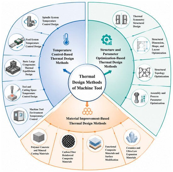
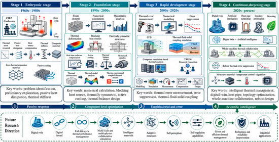
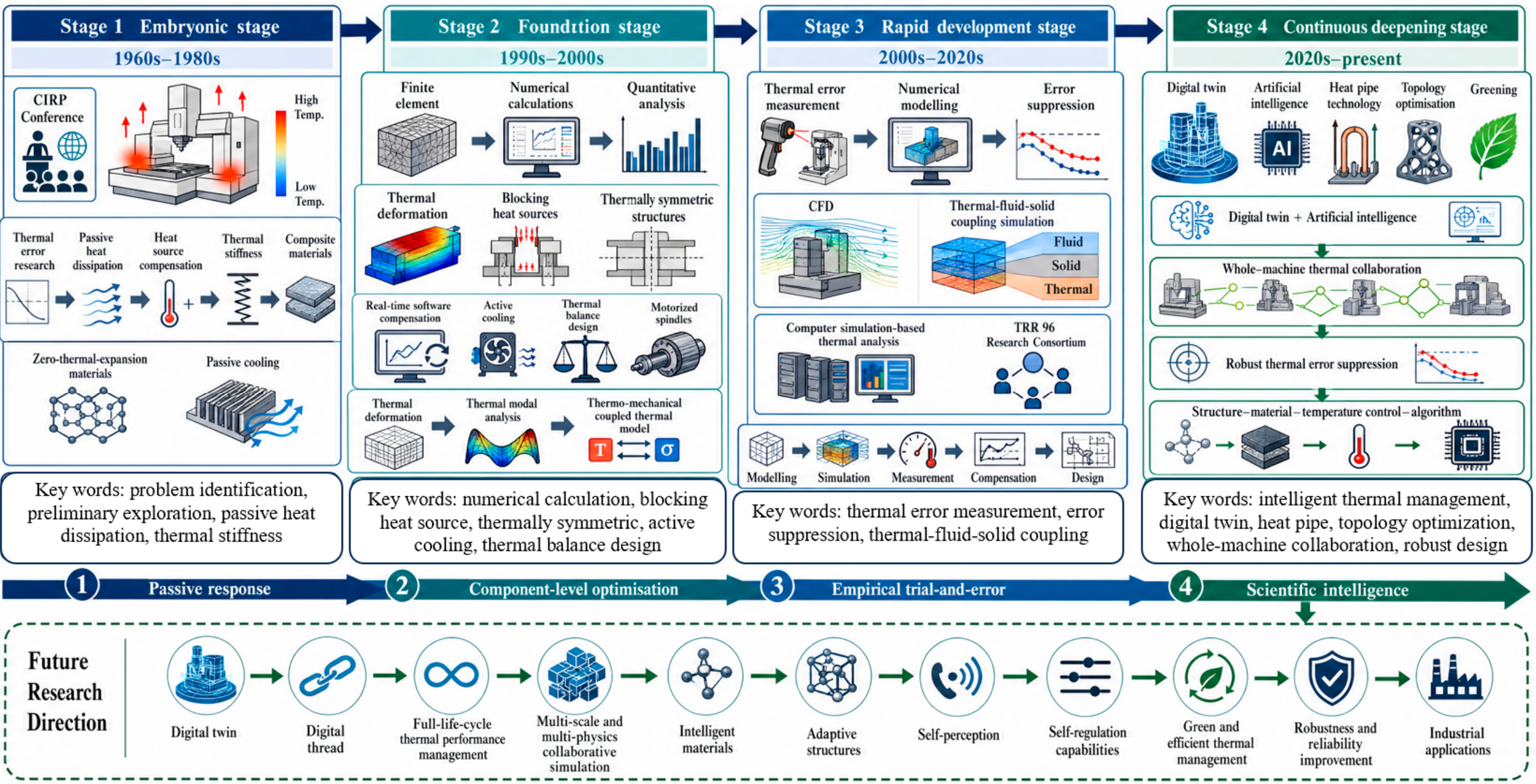
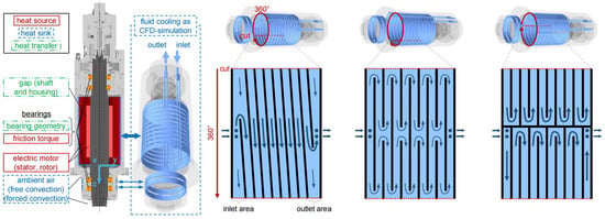
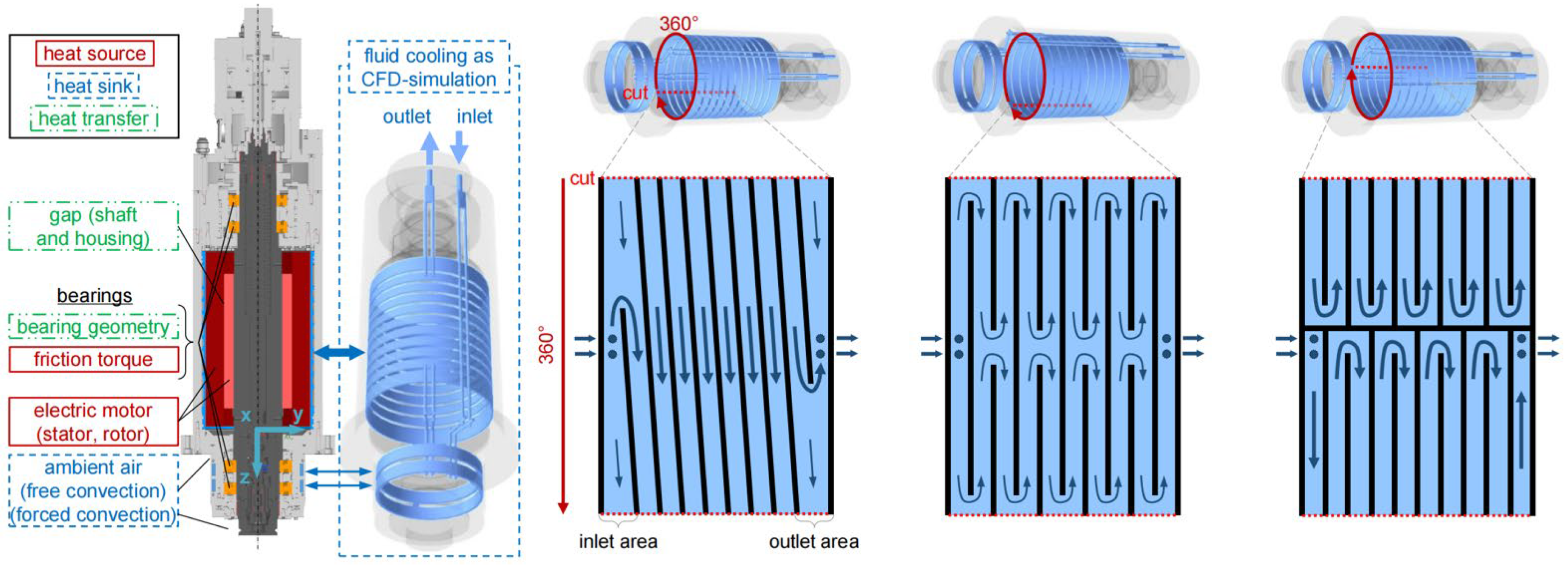
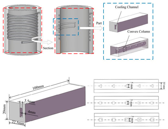
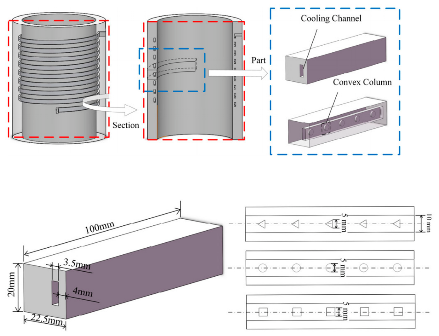
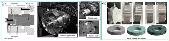
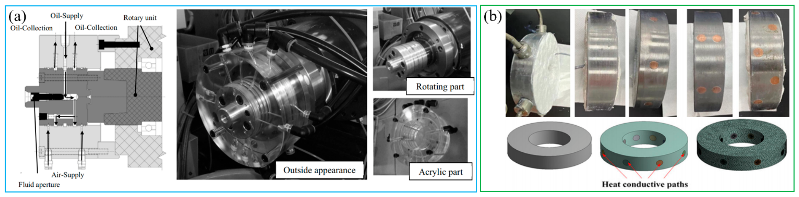
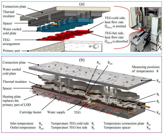
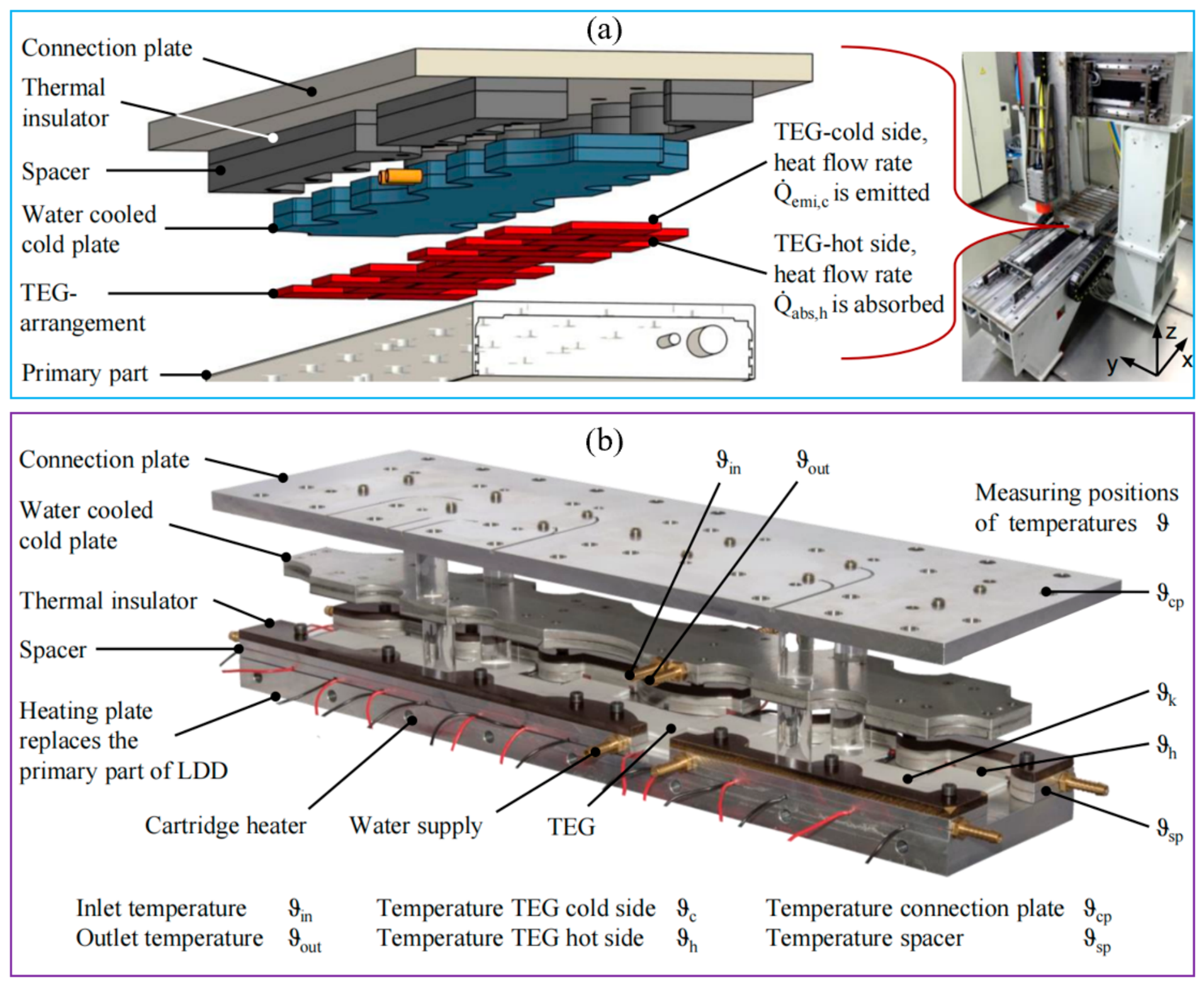
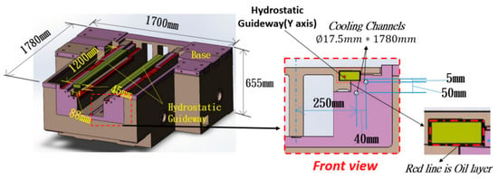
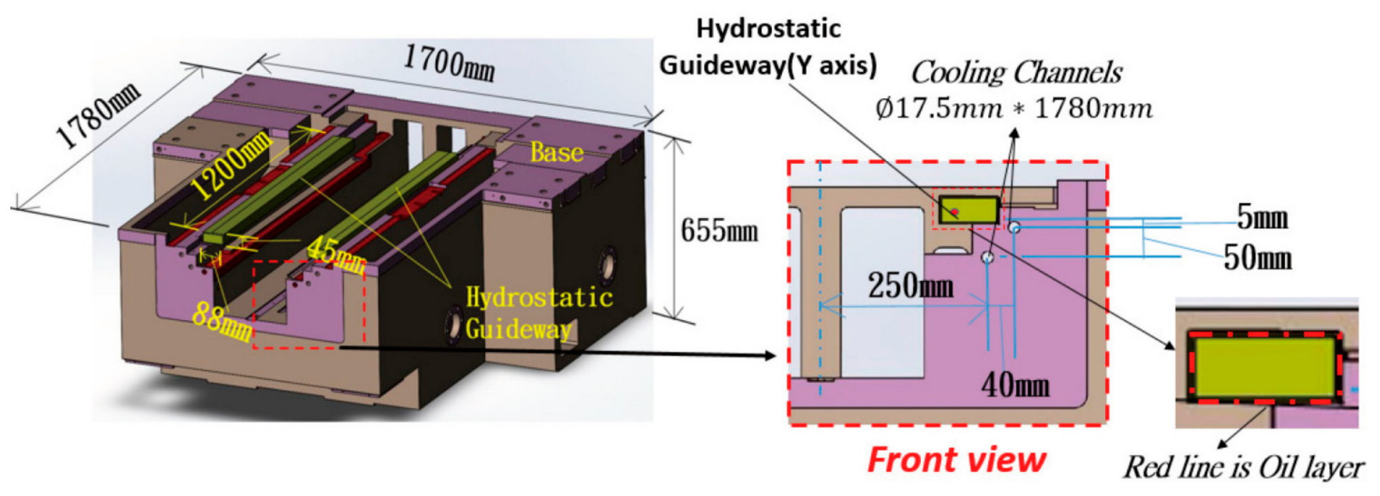
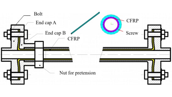
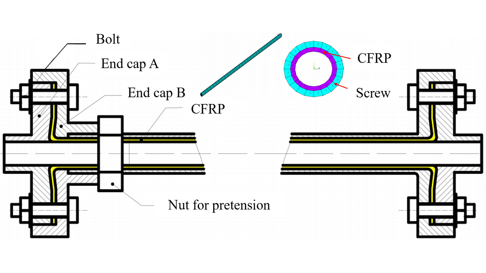
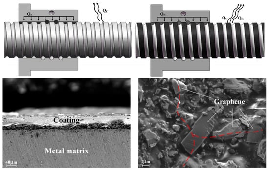
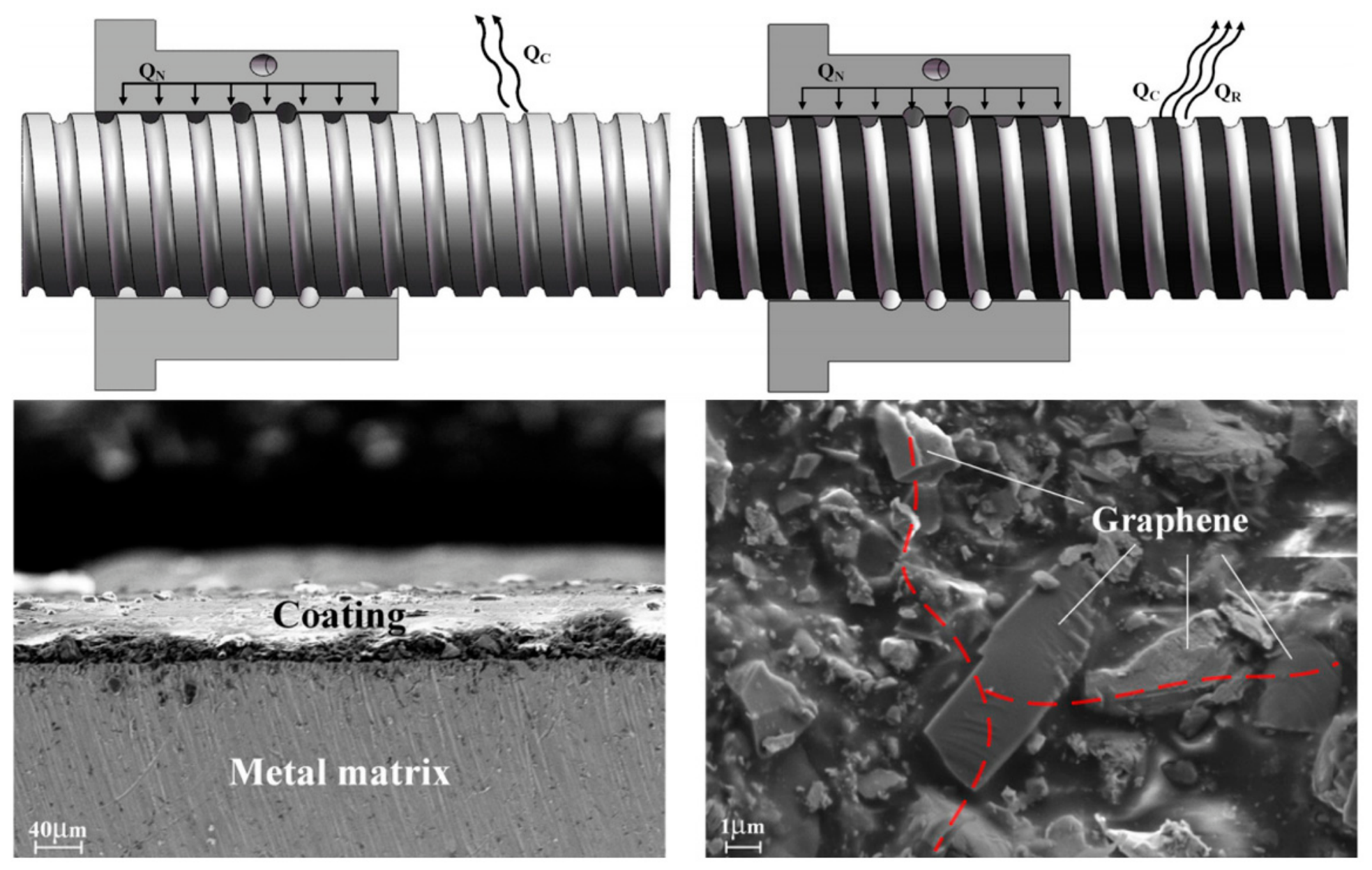
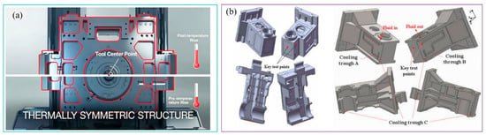
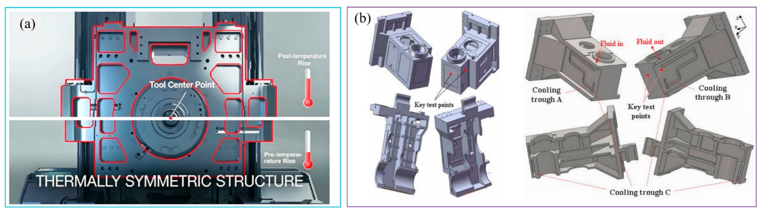
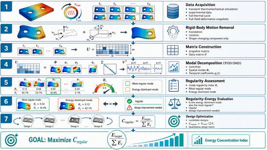
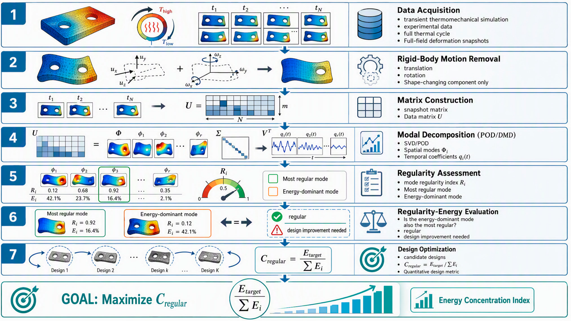

Disclaimer/Publisher’s Note: The statements, opinions and data contained in all publications are solely those of the individual author(s) and contributor(s) and not of MDPI and/or the editor(s). MDPI and/or the editor(s) disclaim responsibility for any injury to people or property resulting from any ideas, methods, instructions or products referred to in the content. |
© 2026 by the authors. Licensee MDPI, Basel, Switzerland. This article is an open access article distributed under the terms and conditions of the Creative Commons Attribution (CC BY) license.