


Abstract
With Industry 5.0, human–robot collaboration has become the center of attention. This has introduced new challenges, where workspaces become highly dynamic, leading to safety concerns for robots and especially for humans. This makes it important to have a realistic and accurate digital representation of a production cell and its components in environments for movement planning and remote supervision. This paper presents a digital twin of a smart production cell, synchronizing objects bidirectionally between a real and virtual workspace with minimal effort using only a single RGB-D camera. A fine-tuned YOLO-based detector identifies tools and items in the scene, estimates their spatial position, and spawns them in Unity relative to the robot via coordinate transformation. Experiments with different scanning velocities demonstrate a mean planar spawn deviation of (standard deviation ) at at height, while maintaining a constant depth bias of . Once spawned, objects can be manipulated freely via drag-and-drop within the simulation. Upon confirmation, a motion planning module calculates trajectories to execute these changes physically. Across 95 trials and 1805 object placements, the system achieves 100% success within working bounds, successfully executing complex tasks such as repositioning objects and stacking them into pyramid structures. The presented system provides a framework to see, spawn, and synchronize industrial workspaces, enabling rapid setup and safe remote supervision of smart production cells in highly dynamic industrial environments.
1. Introduction
Digital relatives, such as digital twins (DT) [1] and digital cousins (DC) [2], have become more popular in recent years. This is mostly due to their ability to quickly adapt to changing environments, prevent damage, and consume less energy than industrial robots [3]. Another advantage is that the movement of the real robot can be planned remotely in advance. This helps to avoid possible collisions with other robots, humans, or the environment. This works quite well in cases of static surroundings, but when it comes to dynamic changes, such as the position and orientation of tools or products, the digital space needs to adapt. This paper presents a digital twin environment for a smart production cell. This environment creates a representation of the current workspace by scanning it with an RGB-D camera mounted on the robot’s end effector. No external image captioning is necessary. AI-based subsystems generate virtual counterparts of objects that can be moved and manipulated. These changes are then fed back to the real robot control system, which performs the planned movement. This technology is ideal for important Industry 5.0 applications where teleoperation from long distances is essential. Its functionality is based on the digital twin environment described in Herrmann et al. [4].
The specific gap addressed in this work is the bidirectional synchronization of objects between a real and digital workspace using only a robot-mounted RGB-D camera. We therefore investigate two questions:
- How do scan velocity and camera distance affect real-to-sim (R2S) object placement accuracy?
- Can changes made in the digital twin be transferred back to the real workspace for grasping and stacking?
To address these questions, two experiments were conducted. The first evaluates the accuracy of placing virtual cube representations at different scanning speeds and camera distances, using only a single robot-mounted RGB-D camera. The success rate and mean planar error were then measured for each cube. Afterwards, these cubes were repositioned in the simulation, whereupon a path-planning algorithm executes the corresponding movement to synchronize the real workspace.
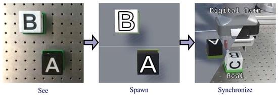
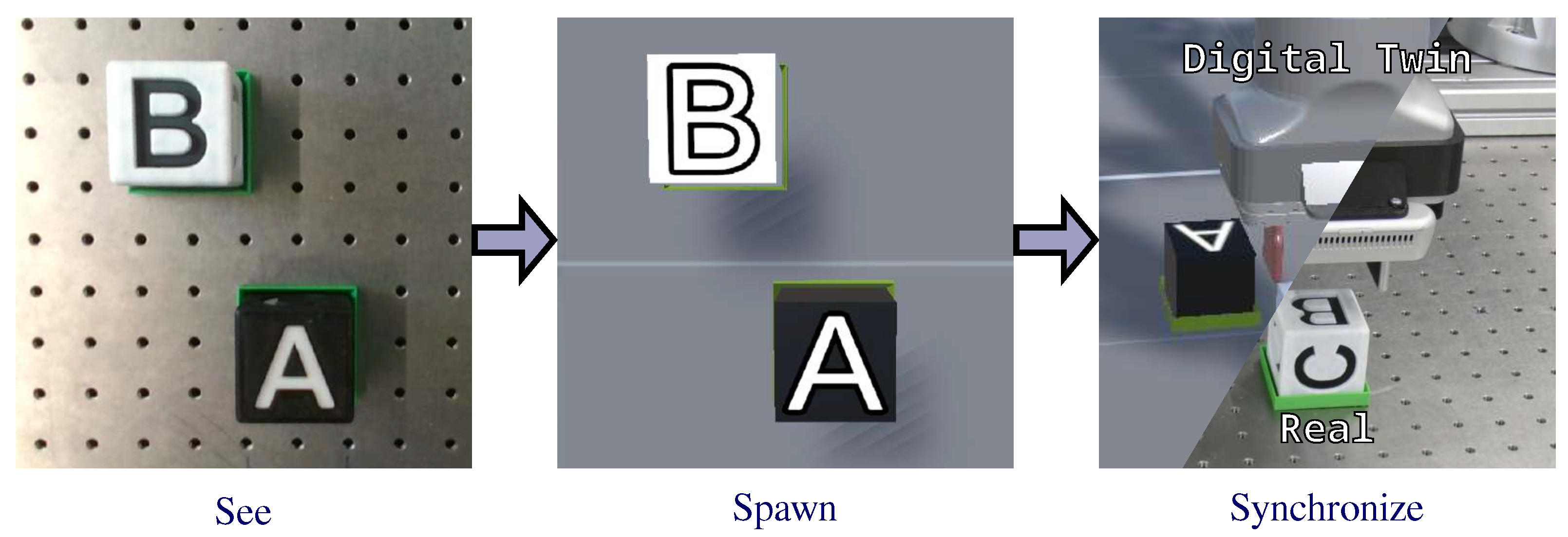
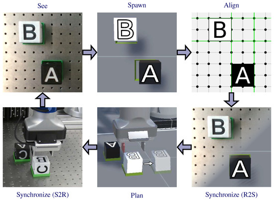
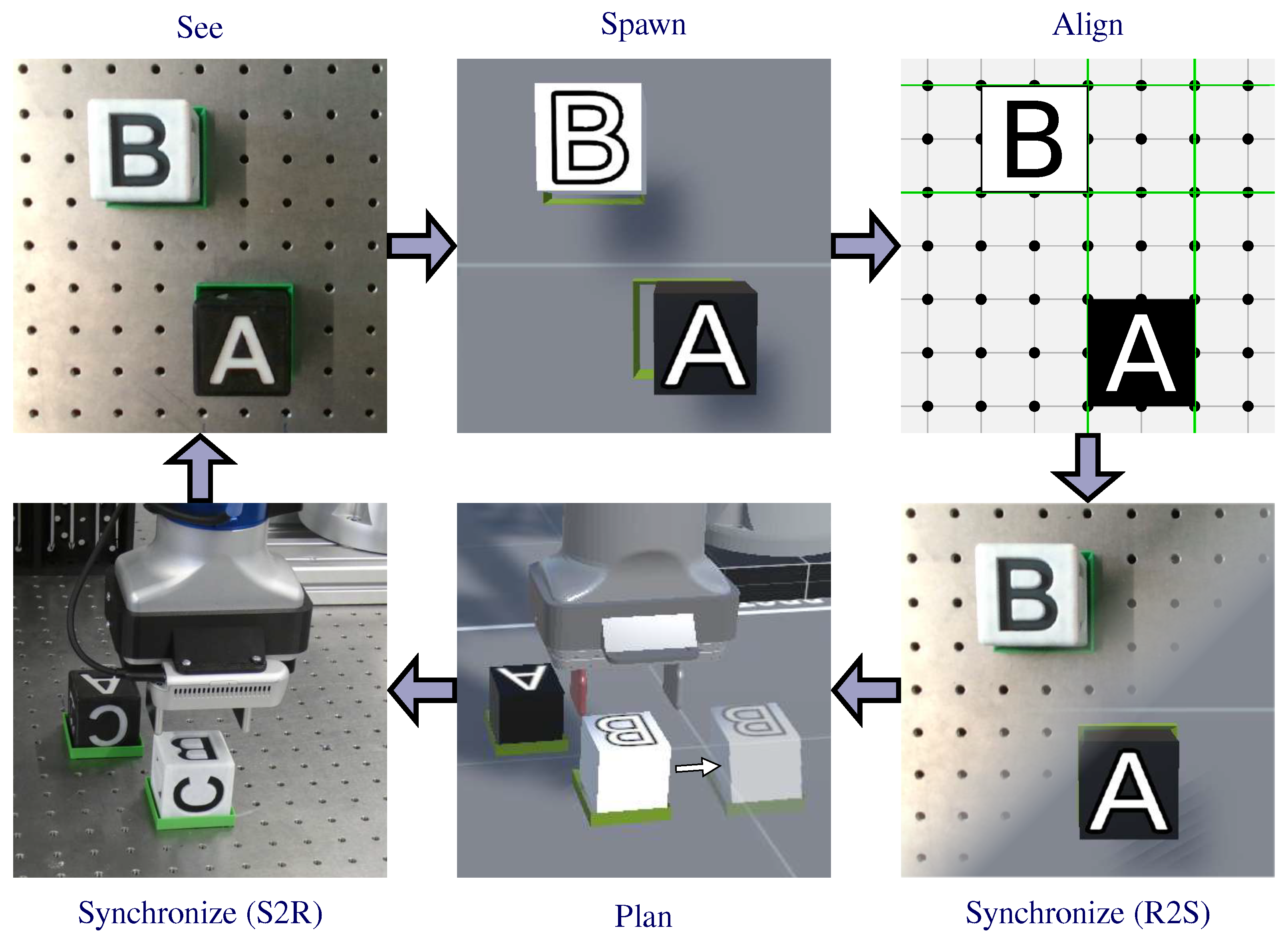
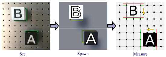
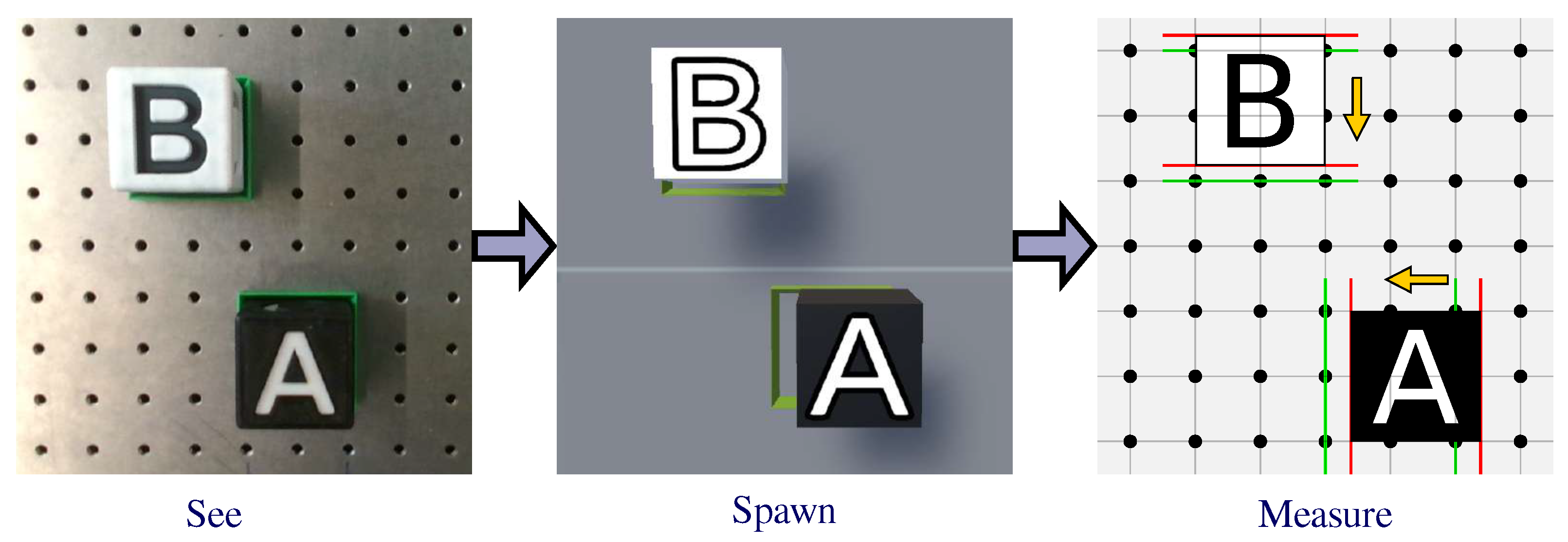
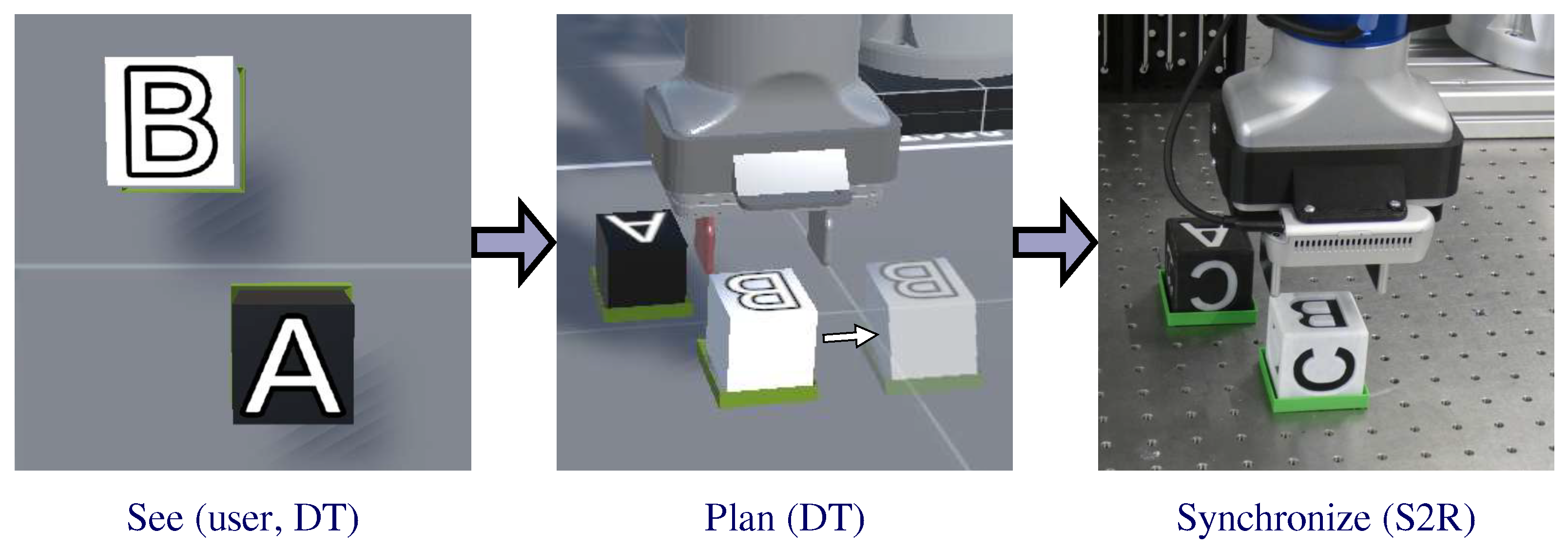
Both experiments follow the see, spawn, synchronize pipeline shown in Figure 1. The first step is to recognize the objects present in the real workspace. Once detected, they are dynamically created in the virtual environment, where they can be moved around to an arbitrary target position. Afterwards, the robot adapts the physical scene according to the plan.
Figure 1.
The pipeline extends from scanning the workspace to placing digital representatives and applying changes in the real world.
In addition to remotely controlling the DT, this functionality allows real-world circumstances and tasks to be set up and transferred into the digital realm. There, reinforcement learning can be applied to the simulation for optimizing actions. This reduces the gap between simulation and reality. The experiments show mean planar errors below at the lower tested scan velocities and demonstrate the transfer of digitally planned object changes back to the physical workspace.
This work is inherently interdisciplinary, synthesizing robotics, computer vision, and digital twin architectures into a unified framework. By bridging physical manufacturing with real-time simulation, it addresses the systemic integration challenges of Industry 5.0. The remainder of this paper is structured as follows: Section 2 reviews the relevant literature; Section 3 details the real and digital workspace setup, the AI perception modules, and the see-spawn-synchronize pipeline; Section 4 presents the experimental evaluation of workspace perception and synchronization; and Section 5 concludes the work and outlines directions for future research.
2. Related Works
A large number of digital twins with various purposes have been developed. In Xiang et al. [5], the digital twin (DT) is used for real-time simulation to visualize and control pick-and-place work tasks. It provides a high refresh rate of and a user-friendly graphical user interface (GUI). A comparison between teaching a real and a digital robot by using a Virtual Reality (VR) user interface leads to a similar task efficiency [6]. To increase the usability, a DT framework with haptic feedback has been developed in [7]. Air-filled pockets indicate to the user whether the gripper has grabbed an object and how stiff the material is. Another approach to control a physical robot via its digital representative has been made in Chang et al. [8]. A graphical user interface (GUI) has been deployed as a control platform, which simplifies the programming of industrial robots. Kawshan et al. [9] developed a framework that can be used for path planning and the real-time execution of robot arms. This framework allows collision-free motion paths to be calculated in just a few milliseconds using the RRTConnect planner. All of the approaches mentioned above use the Unity game engine as the development platform, and some connect to robot networks via ROS or ROS 2.
When it comes to reproducing the real workspace, some DTs use Mixed Reality (MR), in which objects are projected into the user’s view. This is achieved by either detecting fiducial markers or object detection. The system then creates objects that are visible to the user. In Gallala et al. [10] the first method is used to overlay the digital representative directly on the real robot. This allows the user to program the robot without prior programming knowledge by using hand gestures.
The object detection method is used in Wu et al. [11]. An MR framework displays colored cubes, which are detected by an object detector utilizing the RGB-D Image data of the workspace, in a virtual scene. With a VR Headset and Controller, the cubes can be moved to indirectly teleoperate the robot arm.
The SyncTwin, presented by Huang et al. [12], can reconstruct environments using external RGB images of dynamic and partially occluded scenes. This allows for grasp generation even when only limited visual data is available, and path planners can execute safe, collision-aware trajectories on real robots.
3. Method
In order to achieve valuable results, the digital production cell must be recreated as accurately as possible. A precise rebuild helps reduce the gap between simulation and reality. This can be accomplished using the original URDF files from the robot manufacturer, as well as the geometric dimensions of the table and the robot position.
The proposed digital twin has three operating modes. First, it can act as a digital shadow that displays only the current robot configuration and the states of the AI modules. This allows users to monitor the robot’s current state from a remote location. Second, the DT functions as a movement planning tool. When objects are moved, a path planning node calculates the necessary trajectories and sends them to the physical robot system, which then recreates these changes. Finally, the DT can be used for simulation and reinforcement learning purposes without real hardware.
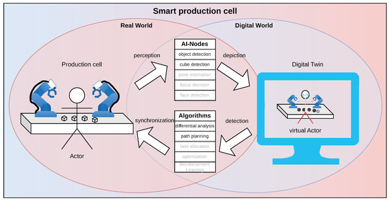
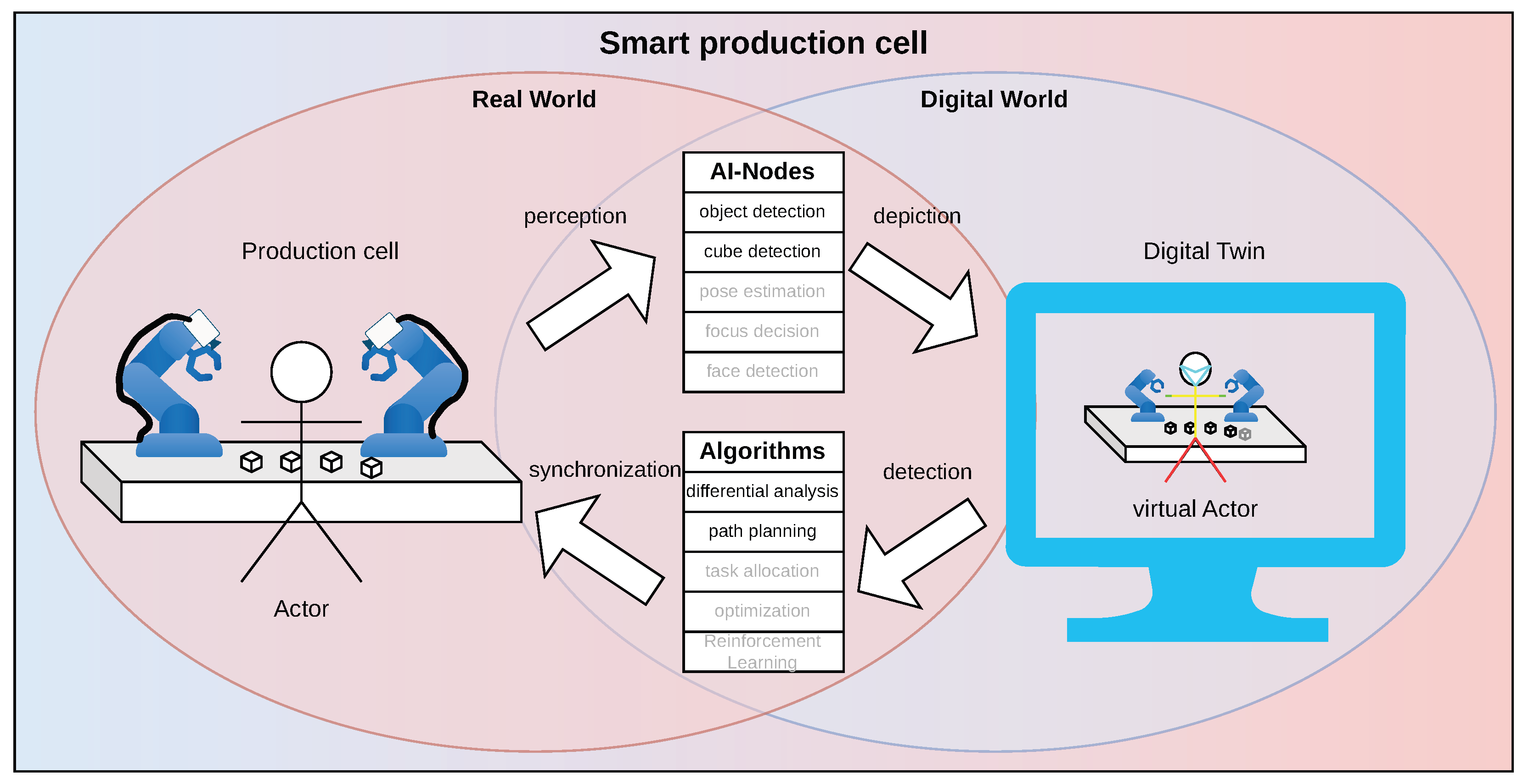
The whole smart production cell, including the real robot and DT, can be divided into four segments. The relevant components are explained in this section and shown in Figure 2. Note that the optional modules marked in gray belong to the broader development platform (e.g., pose estimation, task allocation) and are not evaluated as part of our core see–spawn–synchronize contribution. Within the scoped pipeline, the collected data from the real-world robots (Section 3.1.1) in the workspace (Section 3.1.2) is interpreted by inference modules (Section 3.2.1), forming the see stage. This gathered information is then mapped, spawned, and corrected by the digital twin software (Section 3.2.2). After virtual modifications, algorithms are used to synchronize the changes to the real-world environment (Section 3.2.3). The proposed complete pipeline is described in detail in Section 3.3.
Figure 2.
The schematic diagram of the complete smart production cell. Irrelevant modules for this pipeline are marked in gray.
3.1. Real-World Setup
The real-world setup describes the relevant hardware modalities and workspace.
3.1.1. Robots
The real smart production cell consists of two industry robots from Universal Robots located in a line on the table. The smaller UR5e robot on the left is mounted on a linear axis and is equipped with an RG6 gripper by OnRobot. On the right-hand side of the table sits a UR10e robot with a 2FR14 gripper also by OnRobot. Both robots use Intel RealSense D435 RGB-D cameras mounted on top of their grippers. Although two robots are available, for simplicity and demonstration, only the UR10e robot is used for the experiments. However, all functionalities can be applied to the smaller UR5e robot as well.
To operate both robots on the same PC, the original Universal Robots driver was adapted to use ROS 2 namespaces and joint name prefixes. This enables each robot to be addressed individually and prevents topic name conflicts. Furthermore, namespaces provide a scalable mechanism for integrating multiple physical and digital robots within a single system. The system is thus capable of depicting any reasonable number of real or digital robots, enabling them to exchange data.
3.1.2. Workspace
The physical workspace consists of a table that represents the base of the production cell. Drilled holes (M6) are used to position objects and serve as reference points. The grid of holes is apart in any direction and starts from the corner of the table.
Black and white cubes are used to represent tools, items, or objects present in the production cell. The 3D-printed cubes are on each side and have a different letter or number on each face, which helps to distinguish the cubes.
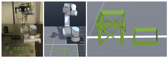
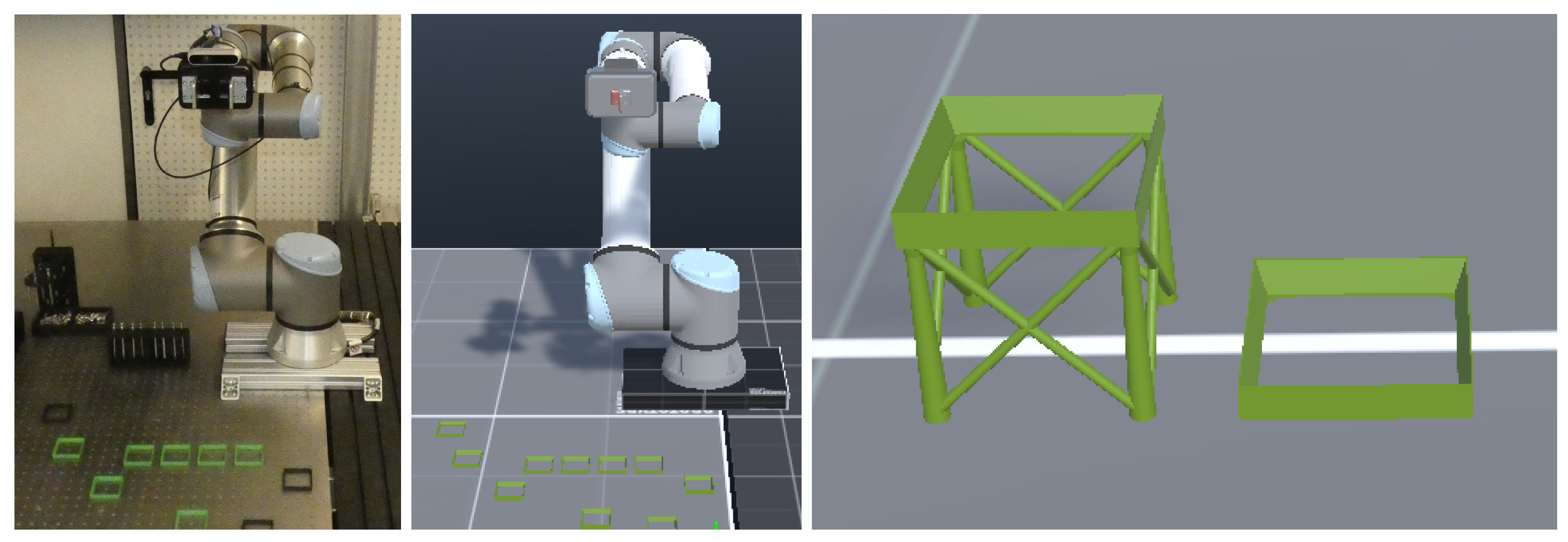
To provide an indication of the measurement, a 3D-printed cube holder in two different heights (see Figure 3, right) has been designed. The CAD files can easily be integrated into the simulation. Different scenarios can be created by arranging the cube holder close together or far apart on the table. They simplify cube positioning in the real world, because a slope enables the cubes to slide into position and they fit exactly in the holes of the table. In the simulation, they function as a fiducial marker to calculate the spawning error.
Figure 3.
Setup of the smart production cell: (Left): real UR10e robot; (center): digital twin; (right): two 3D-printed cube holders, one tall and one floor-height.
3.2. Digital-World Setup
In the digital world, all the components of the functional digital twin converge. Cameras mounted on the real robot collect images that are interpreted by various AI perception algorithms. This information is then used to recreate the workspace in the simulation. The DT is implemented in Unity and connected to the ROS2 via a ROS-TCP-Endpoint (https://github.com/Unity-Technologies/ROS-TCP-Endpoint) (accessed on 28 May 2026). Unity, as a gaming engine, allows users to manipulate and interact with objects in multiple ways and depict them realistically for detection algorithms to work. The underlying modular design of Unity also accommodates upcoming extensions, notably VR support and integration of pose estimation pipelines. Currently, the user can move the DT objects on the screen using a mouse, touch, or a gaming controller. Once the user acknowledges the changes in the DT, the positions of the source and target cubes are sent via ROS2 to the path planning node. The node calculates a trajectory and sends it to the real robot controller to accomplish the task. More detail is provided in the following subsections.
3.2.1. AI-Perception
Perceiving one’s surroundings is essential for handling the robot safely. To achieve this, RGB and depth images are transferred via the ROS2 network and fed into multiple perception nodes. For object/cube detection, the object detection network Ultralytics YOLO11 [13] has been fine-tuned with data from the black and white cubes used for the task. The output provides information about the bounding box, rotation, and the type of object in the image, respectively. In this case, the object is the topside letter. To determine the distance to the camera, the aligned depth image is taken into account. The depth value is picked at the intersection point of the diagonals of the bounding boxes. Due to the gravitational pull of the physics engine in Unity, however, the depth value does not need to be very accurate because the cubes are falling into place.
For the cube spawning, a positioning module was developed. It subscribes to the bounding boxes topic and translates this information to be interpretable by Unity. The cube spawn point is calculated with respect to the camera position with the help of the intrinsic camera parameters. Unity implicitly has transformation matrices for the kinematic joints of the robot; thus, the extrinsic camera parameters are only used for the placement of the camera. As the depth images only provide the distance to the top and the cube’s origin is in the middle, an offset of , half the cube’s height, needs to be taken into account. A tracking algorithm prevents multiple spawning of the same object by keeping track of detected cubes and filters out singular events under 7 frames.
As the Unity framework is capable of processing shaders, an RGB-D camera can also be fully simulated. Thus, digital representatives can use the same perception algorithms with simulated image data (RGB and Depth) or real sensor data, making the sim-to-real (S2R) transition easy and reversible.
3.2.2. Digital Twin
Unity was chosen for the implementation of the digital twin because of the variety of opportunities and aforementioned benefits. The dynamic and presentable visualization of models and objects, in combination with an included physics engine, makes it the optimal tool [14]. The workspace was measured and rebuilt by scale as 1 unit in Unity corresponds to in the real world. The robot and gripper models were imported with the help of an URDF-Importer (https://github.com/Unity-Technologies/URDF-Importer) (accessed on 28 May 2026), provided by Unity itself. With the ROS-TCP-Endpoint application, the joint states topic from the real robot is subscribed and applied to the models’ joints. This mirrors the actual movement in real time.
The spawn root point is defined by the camera, relative to the robot base. Due to the underlying URDF files and known joint states, this position can be made very precise. Since the spawner node outputs data relative to the camera frame, only translating pixel coordinates to world coordinates is required.
Once spawned, the virtual cubes can be moved around the digital workspace by the user (touch, mouse, gamepad). They can be placed on the table or stacked on top of each other. To help with visualization, a ghost version of the cube appears in the simulation to indicate the target position.
A GUI provides buttons to acknowledge and execute the changes, to align the cubes to the grid or to undo the changes. Confirmation sends a ROS2 message to the execution planning node, which is described in Section 3.2.3. As the simulation is still subscribed to the joint states topic, both the execution of the real robot task and the movement of the virtual cubes are displayed in real-time, considering the built-in physics engine. Operators can compare the real world with the simulation as both real and simulated cameras outputs are displayed.
3.2.3. Task Execution Planning
Task execution is needed to transfer the differences made in the simulation to the real world, as opposed to differences from real world to simulation, which are calculated using perception and robot states.
Upon receiving the workspace coordinates from Unity, the task execution planning module organizes the cube positions by z-height to establish a valid stacking sequence. Using this information, the planner computes the necessary trajectories for approach, grasping, translation, and release.
To ensure safe movement and collision avoidance, the dimensions of obstacles and the table are sent to moveIt (https://moveit.ai/) (accessed on 28 May 2026), a motion planning framework. Using this information, possible paths for each sub-task can be calculated. As the gripper only needs to open and close, a signal is sent to a separate gripper controller. This process is repeated for every displaced cube in the simulation.
3.3. Pipeline
Figure 4 represents the main experimentally evaluated pipeline, which corresponds to the essential (non-gray) modules of Figure 2. First, the real workspace is scanned to locate the objects. The calculated position is then sent to the digital twin framework for spawning. Due to noise and inaccurate detection caused by movement, there may be a discrepancy in the position. To overcome this R2S gap, a priori knowledge about the workspace (cubes are on a grid) can be applied, and an alignment process snaps the cubes to the defined fiducial markers (cube holders). Thus, the R2S synchronization is completed.
Figure 4.
The complete digital twin pipeline for synchronizing real and digital production cells.
From this point onwards, motion planning can be carried out in the digital workspace. This is indicated by a transparent version of the source object. After the task has been approved, the robot performs the S2R synchronization by displacing the objects to align both production cells. The pipeline can then be repeated using a new workspace scan to detect differences, such as the addition or removal of objects in the real world.
To evaluate the pipeline, the process was split into two separate experiments for the detection and manipulation (S2R Synchronization) parts.
4. Experiments
Two experiments were conducted during the development process. The first experiment demonstrates the accuracy with which the cubes are detected and placed at different velocities within the simulation workspace. The necessary displacement needed for the cube alignment between the spawned DT cubes and real world indicates the precision and accuracy of the see, spawn part. The success rate of the actual grasping of the detected cubes before alignment indicates the efficiency of synchronize, the second part of the pipeline.
4.1. Experiment 1: Workspace Perception
This experiment demonstrates the accuracy of cube spawning at different velocities when recreating the current workspace, enabling interaction with cubes in the simulation.
4.1.1. Setup
The holes drilled in the real table are used to determine the placement. The position of the right front hole is indicated with a digital transformation frame. All fiducial markers have been positioned according to the original from this origin.
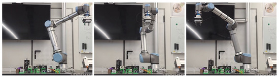
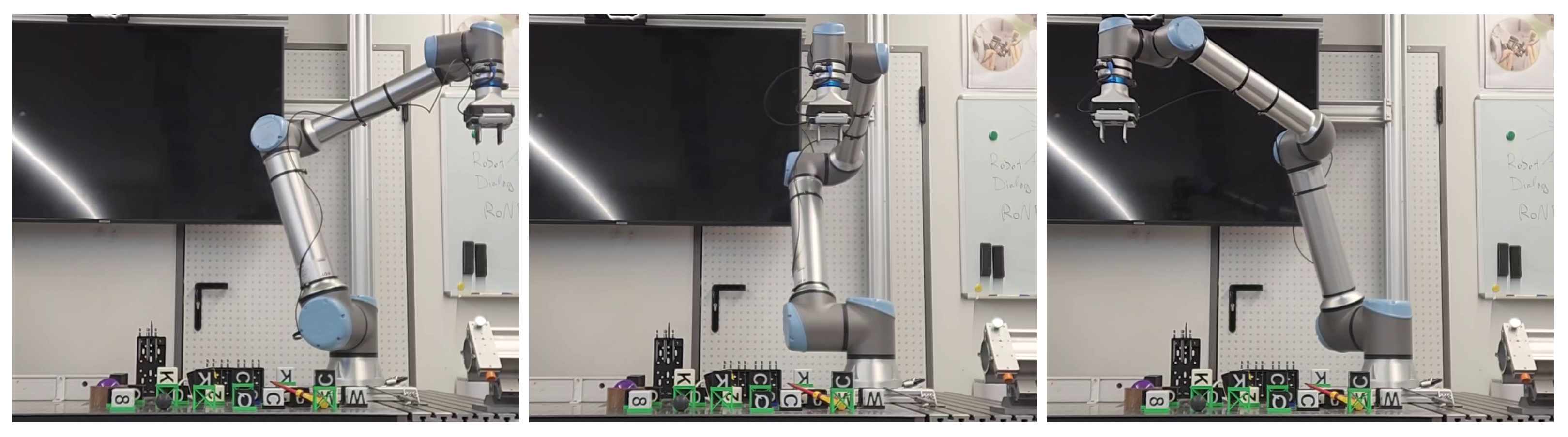
A trajectory is planned to move the tool center point orthogonally to the table’s surface. Starting at the viewer’s right-most side, it moves at a constant speed parallel to the long edge to the viewer’s left-most side. The motion is visualized in Figure 5. The cubes are then spawned in Unity with the detected top-side letter. The height of the camera above the table is set between and over all experiments. A range of speeds was used to conduct a comprehensive evaluation. The velocities considered were , , and meters per second. Each velocity is performed 100 times. The digital workspace is cleared between every trial, setting up a completely new environment. The offset of each spawned cube to the fiducial marker is measured and evaluated. This procedure is visualized in Figure 6.
Figure 5.
Movement of the Workspace scan. It is started on the viewer’s right-hand side, transitioning linearly to the left-hand side.
Figure 6.
Procedure of the first experiment. The scanning of the cubes, their digital spawning and their alignment to the closest marker.
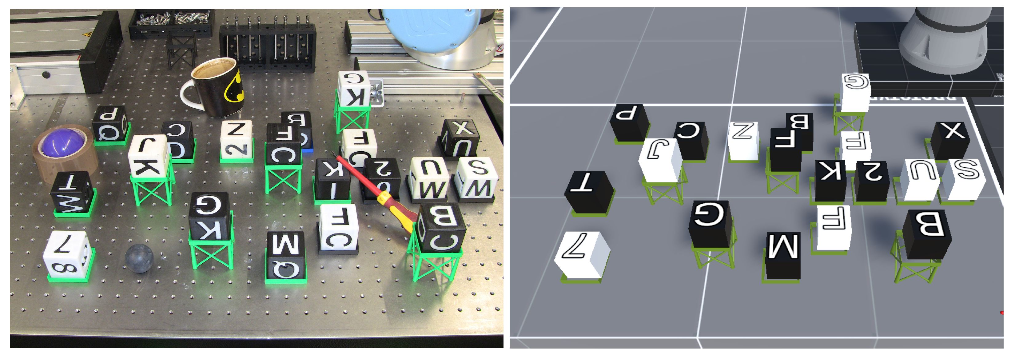
For this experiment, cubes were placed inside these markers in the real world. The color and top-side letter were determined at random. Since tools and products in a real environment can be occluded, some distracting items were placed around the cubes. These can be seen on the left in Figure 7.
Figure 7.
The real and reproduced workspace. The cubes were placed randomly. Various objects have been placed to create occlusions. All cubes have been detected correctly.
4.1.2. Measurement Methodology
The following aspects have been measured:
- Planar error : 2D distance between spawned cube position and ground-truth slot position in the XY plane (plane of the table surface), using Equation (1).
- Bias components: Individual X, Y, Z bias values per cube.
- Success rate: Percentage of trials where all 19 cubes were successfully matched.
- Inside holder bounds: Percentage of cubes within physical holder boundaries.
- Within tolerance: Percentage of cubes within acceptable placement tolerance.
- Height error: Z-axis difference between spawned and ground-truth position.
- Ground truth: Known positions from the hole grid ( spacing + cube holders).
- Detected positions: YOLO11 bounding box + depth value + half cube height.
- Coordinate transformation: Camera intrinsic parameters + URDF joint transforms.
- Matching: Each detected cube was matched to its corresponding slot by cube label.
4.2. Evaluation Experiment 1
Validation data was collected across 4 experimental conditions combining different camera distances and scan speeds. During the experiment, we encountered minimal data loss on the last 5 trials for one condition. To keep the data balanced, the last 5 trials were trimmed for all conditions, thus resulting in 95 trials each. No manual trial picking was done.
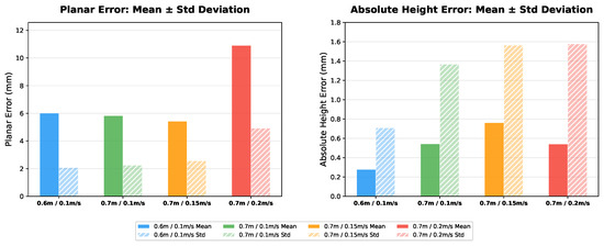
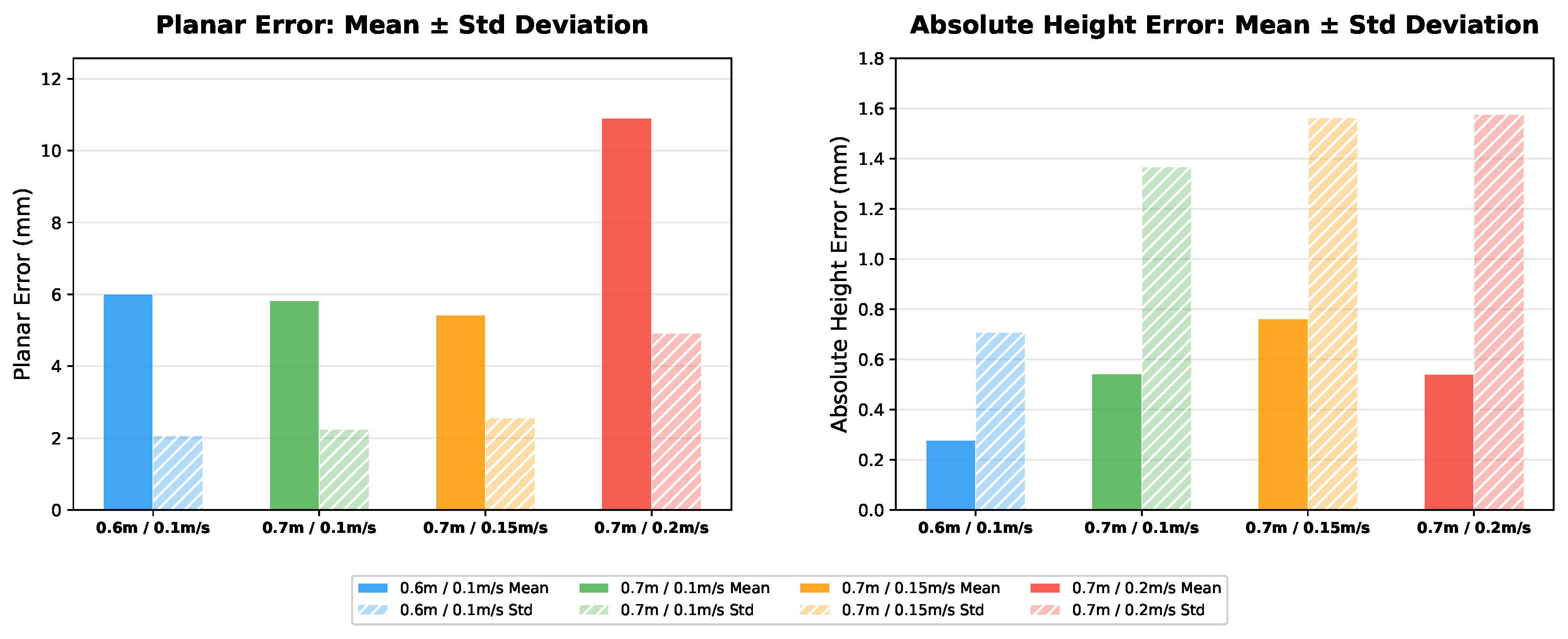
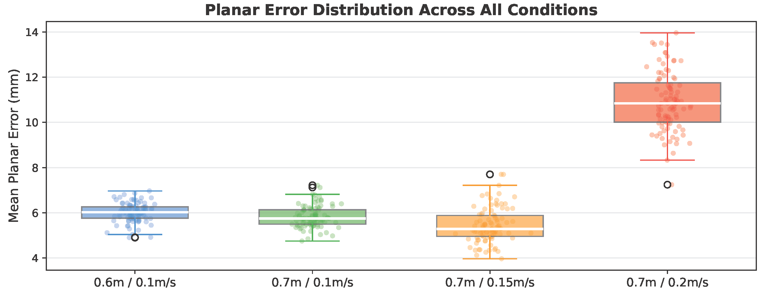
The following evaluates how scanning velocity affects planar error and height bias. Table 1 summarizes the key metrics, and Figure 8 provides a detailed comparison of planar and height errors. Figure 9 shows the overall planar error distribution.
Table 1.
Summary of results by condition. (Mean, Std, P95) and z, height bias in mm.
Figure 8.
Planar and height error metrics (mean and standard deviation) for all conditions.
Figure 9.
Overall planar error distribution across all conditions.
4.2.1. Scan Speed Impact
Increasing the scan speed from to nearly doubled the mean planar error from to —an 89.6% increase. This was statistically significant (, Mann–Whitney U test) across all pairwise comparisons. The P95 error grew from to , indicating that worst-case placements are disproportionately affected.
The number of detections decreased from 1805 to 1767 (2.1% loss), indicating that a compromise between scan speed and accuracy must be made. For the workbench, the scan motion takes 4, , or , depending on the scan velocity. This motion accounts for a major part of the overall synchronization time. YOLO inference and the subsequent computations are processed within the duration of a single camera frame (), allowing the perception pipeline to operate at the camera rate. For stability and to avoid repeated spawning at almost the same position, a detection must currently persist for seven frames before it is accepted. This configurable filter introduces an additional delay of up to approximately during workspace scanning. For a single synchronization while the robot is stationary, the system can operate at the camera refresh rate.
4.2.2. Per-Letter Accuracy
Planar spawning accuracy varied by cube letter/number. Letter J achieved the lowest mean error (), while X showed the highest ()—a 36% difference. This suggests that visual features such as letter shape, contrast, and color combination may influence the localization accuracy (see Table 2).
Table 2.
Mean planar error per cube letter/number.
4.2.3. Bias Analysis
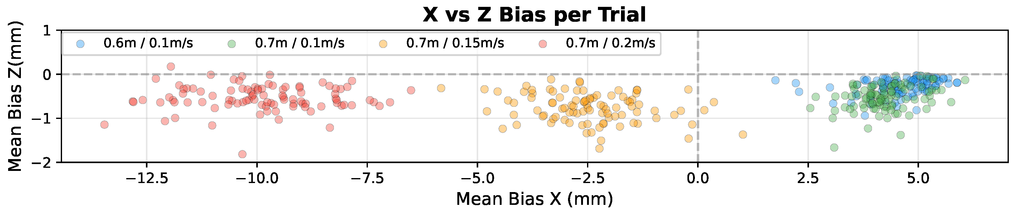
A consistent negative Z-axis bias of approximately was observed across all conditions. This systematic offset may be related to the depth measurement methodology: depth is measured at the cube’s top edge rather than its center, and the offset correction is not perfectly accurate due to camera angle variations. The scatter plot depicting the bias for each trial can be seen in Figure 10.
Figure 10.
X vs. Z bias scatter plot across all conditions.
4.3. Experiment 2: Workspace Synchronization
This experiment demonstrates qualitative synchronization between both production cells when changes have been made. This involves observing the cubes and then creating, aligning, and repositioning them in the digital twin, and then transferring the adjustments to the real world.
4.3.1. Setup
A number of holders with a cube inside are placed on the table. In order to transfer them to the digital twin environment, a new scan of the workspace needs to be recorded. After the cubes have been spawned, the R2S gap is reduced by aligning them with their closest holder. To plan a task, the user places ghost versions of the cubes onto other cubes by drag-and-drop. Once the changes have been acknowledged, the motion planning node calculates the robot’s trajectories to complete the task. Figure 11 describes the second part of this experiment, since the first part has already been mentioned.
Figure 11.
Procedure of the second experiment. The user sees the cubes, plans a movement and the changes are synchronized in the real world.
4.3.2. Evaluation
Because this experiment builds directly on the previous one, the results strongly depend on the quality of the scan and the subsequent cube detection. For the evaluation, a trial is considered successful when the cube is correctly grasped both in the digital twin and by the real robot. A failure is defined as any case in which the real robot does not grasp the cube correctly, regardless of the state observed in the digital twin.
Each cube has an edge length of , while the gripper has a maximum opening of . This allows the gripper to compensate for an approximate misalignment of along the X-axis. Due to the orientation of the gripper, misalignment along the Y-axis is less critical, since the gripper can still grasp the cube even if it only partially overlaps with it. The same applies to small deviations in the height estimate. In contrast, an X-axis misalignment greater than is likely to cause a collision or failed grasp.
The alignment mechanism assigns each detected cube to the nearest grid position. For this assignment to be correct, the detected cube position must lie within of the corresponding grid point. Based on these criteria, a cube is considered directly graspable if its X-axis error is within . If the cube is outside this range but still within the alignment tolerance, it requires compensation through grid alignment.
Using these rules, the success rates are summarized in Table 3. The raw success rate represents the proportion of cubes with an X-axis error within before correction. The compensated success rate shows the proportion after applying the condition-specific X-axis drift correction. This correction is based on the mean bias measured in the previous experiment for each height and speed condition. By compensating for this systematic drift, the R2S gap and scan-induced misalignment are reduced.
Table 3.
X-only grippability results.
For the best-performing condition (, ), the raw grippability rate is , while the compensated grippability rate increases to by eliminating the systematic, measurable bias. This demonstrates that the dominant source of grasping failure is not random detection noise alone, but a systematic X-axis drift that can be substantially reduced through bias correction. The improvement is visible across all tested conditions. The a priori knowledge of how the objects are expected to be placed further increases the gripping chance by aligning the cubes to the grid.
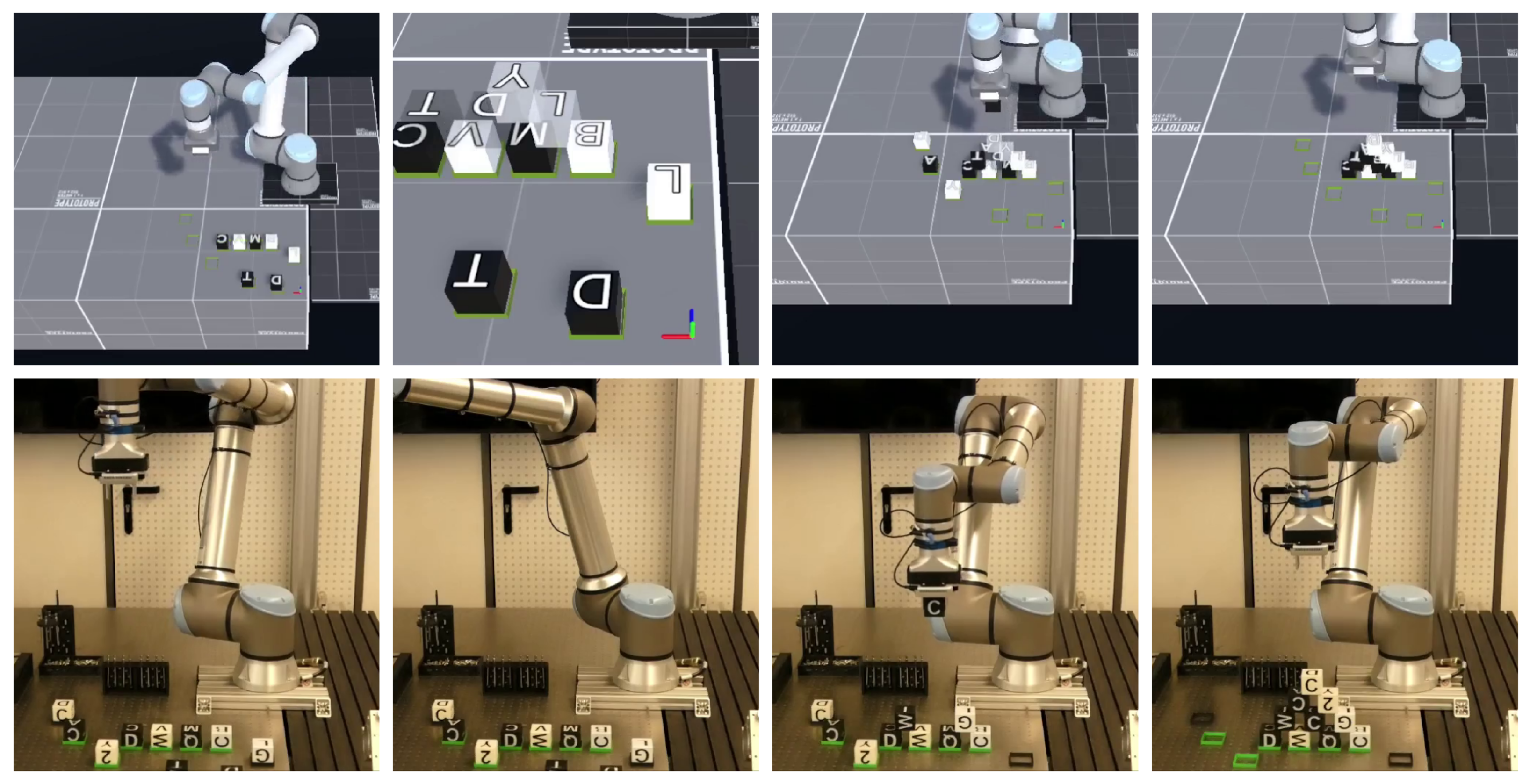
For the qualitative part of the experiment (proof-of-concept), a scan with the optimal conditions (, ) was used and a task to build a 4-3-2-1 pyramid was conducted using only the DT after a single scan. Excerpts from the Supplementary Material are shown in Figure 12. The gripping rate for real and sim robots was , demonstrating the capabilities of the see, spawn, synchronize pipeline.
Figure 12.
Procedure of building a pyramid: Scan the workspace—position target cubes—stack cubes—finish task.
The evaluation in this work focuses on the complete pipeline. The contribution of the individual modules was not isolated experimentally, and error propagation from detection through spawning and task execution was not measured separately. Different lighting conditions, systematic levels of occlusion, alternative sensor configurations, planner comparisons, and objects with different geometries or surface properties were not evaluated. These aspects limit the generalization of the presented results and should be evaluated in future work.
The figures and schematic diagrams were created in Inkscape (v.1.4.4) and retained as vector graphics where possible. For figures combining real and virtual views, images were captured using the robot-mounted or an external camera, and the corresponding Unity viewpoint was adjusted using partial transparency until a visual match was obtained; this alignment was used only for visualization and not for quantitative evaluation.
Videos of both experiments can be found in the Supplementary Materials.
5. Conclusions
This paper presents a proof of concept for a digital twin that synchronizes real-world and digital workspaces bidirectionally, including their respective objects. It can also detect differences, which are then synchronized with the physical robot. The workspace scan works well in our conditions, when a velocity of at a height is used. The mean planar error amounts to just . At the highest tested velocity of , the mean planar error increased to . Therefore, slower scan velocities are preferred under the tested conditions. Experiments have shown that height does not impact spawn accuracy except for along the Y-axis. This is because the camera is tilted toward the gripping space for a better view under other circumstances. This directly corresponds to the main practical difficulties during the implementation: the reduced placement accuracy at higher scan velocities and the adjustments needed to maintain stable detections during robot motion.
Because of the bias being larger in the X-direction (the direction of scan movement) than in the Y-direction, rotating the gripper by 90° around the Z-axis would lead to a higher grasping success rate. The S2R synchronization function has been qualitatively validated. Placing target cubes on top of each other was easily done. While synchronizing the real workspace, the digital twin carried the digital cubes in the same way that the real cubes were carried. A four-cube-high pyramid was stacked successfully.
Regarding the first research question, scan velocity had a clear impact on R2S placement accuracy, while the tested change in camera distance had only a small effect on the mean planar error. Regarding the second research question, the experiments demonstrate that changes introduced in the digital twin can be transferred back to the real workspace for grasping, repositioning, and stacking.
Future Work
For the time being, the placement of cubes is limited by the accuracy with which they are detected. Currently, only the position and top letter are detected. However, an enhancement of the detection nodes is currently in development which will also estimate the 6D pose of the cube. With this feature, cubes can be spawned in all orientations around the workspace, leading to more dynamic motion planning. As the cube detection is based on a YOLO network, the approach can also be trained for objects from datasets such as the COCO dataset [15]. Using the detected bounding box, depth values, and a corresponding label, it would be possible to create such objects in real time. For example, a remote control has a rectangular shape. By identifying the difference in depth values, inside and outside the bounding box, a cuboid or some other shape can be generated. A label indicating the type of object can be added on top. If digital representations of these objects are already available, they can be scaled to the size detected and displayed in the digital workspace.
The pose estimation AI module uses mmpose (https://github.com/open-mmlab/mmpose) (accessed on 28 May 2026) to predict human poses and output the skeletal posture (COCO 17-point keypoint names) of people standing in front of the camera. The distance of each keypoint is also taken from the depth image. This enables the person’s model to be displayed correctly in front of the robot. Combining this model with virtual reality functionality gives the impression of standing right in front of the real robot, since the digital version can react to the virtual human by focusing on the face. By detecting the hand position, the manipulation of the objects can be done intuitively.
The next step is to integrate the additional modules that have already been implemented in the real robot system. These include face detection and recognition, focus decision, and head pose and pose estimation, all of which have been mentioned previously. This brings the digital twin closer to the real production cell.
Since the cubes do not reflect reality, they can be scanned to create a digital version. With the help of Neural Radiance Fields, this can be achieved by simply taking a few images of the object, as described in Schulz et al. [16]. At lower scan speeds, images can be captured and the object generated in real time.
Future work could also investigate adaptive scan velocities based on object density or geometry. A further improvement could also be to replace the fixed seven-frame threshold with a confidence-based acceptance criterion. High-confidence detections could then be accepted after fewer frames, potentially reducing the additional delay while retaining stability.
Supplementary Materials
The following supporting information can be downloaded at https://www.mdpi.com/article/10.3390/machines14090972/s1, Video S1: Automatic workspace scanning, object detection, and digital twin synchronization; Video S2: Bidirectional synchronization between the digital twin and the physical production cell during a pyramid stacking task.
Author Contributions
Conceptualization, M.H.; methodology, M.H.; software, M.H. and D.S.; validation, M.H. and D.S.; data curation, D.S.; writing, M.H. and D.S.; visualization, D.S.; funding acquisition, A.A.-H.; project supervisor, A.A.-H. All authors have read and agreed to the published version of the manuscript.
Funding
This work was supported in part by the European Regional Development Fund (ERDF) through ENABLING under Grant No. ZS/2023/12/182056, RoboLab under Grant No. ZS/2023/12/182065, KIRA under Grant No. ZS/2025/09/206793 (STEP Program), by the Investment Bank of Saxony-Anhalt (IB-Sachsen-Anhalt) through AI Co-Working Labs under grant No. ZS/2024/01/183362, and by the Federal Ministry of Research, Technology and Space of Germany (BMFTR) through Edison under Grant No. 13N17576.
Data Availability Statement
The datasets presented in this study are not readily available because they require additional curation and documentation before public release. Requests to access the datasets should be directed to the corresponding author.
Acknowledgments
During the preparation of this manuscript, the authors used DeepL (https://www.deepl.com/) (last accessed on 16 July 2026) for English language editing and GitHub Copilot (https://github.com/features/copilot) (Release: 20 May 2026) to assist with software implementation by generating and suggesting source code. All generated text and code were reviewed, validated, and modified as necessary by the authors. The authors have reviewed and edited the output and take full responsibility for the content of this publication.
Conflicts of Interest
The authors declare no conflicts of interest.
Abbreviations
The following abbreviations are used in this manuscript:
| DT | Digital Twin |
| VR | Virtual Reality |
| S2R | Sim-to-Real |
| R2S | Real-to-Sim |
| MR | Mixed Reality |
| URDF | Unified Robot Description Format |
References
- Singh, M.; Fuenmayor, E.; Hinchy, E.; Qiao, Y.; Murray, N.; Devine, D. Digital Twin: Origin to Future. Appl. Syst. Innov. 2021, 4, 36. [Google Scholar] [CrossRef] [Scilit]
- Dai, T.; Wong, J.; Jiang, Y.; Wang, C.; Gokmen, C.; Zhang, R.; Wu, J.; Fei-Fei, L. Automated creation of digital cousins for robust policy learning. arXiv 2024, arXiv:2410.07408. [Google Scholar]
- Landscheidt, S.; Kans, M. Method for Assessing the Total Cost of Ownership of Industrial Robots. Procedia CIRP 2016, 57, 746–751. [Google Scholar] [CrossRef] [Scilit]
- Herrmann, M.; Hempel, T.; Al-Hamadi, A. A Real-Time Digital Twin Framework for the TIAGo Service Robot. In Proceedings of the 2025 IEEE International Conference on Systems, Man, and Cybernetics (SMC), Vienna, Austria, 5–8 October 2025; pp. 6065–6068. [Google Scholar] [CrossRef] [Scilit]
- Xiang, T.; Li, B.; Pan, X.; Zhang, Q. Development of a Simple and Novel Digital Twin Framework for Industrial Robots in Intelligent Robotics Manufacturing, Bari, Italy; IEEE: Piscataway, NJ, USA, 2024; pp. 4187–4193. [Google Scholar] [CrossRef] [Scilit]
- Kuts, V.; Marvel, J.A.; Aksu, M.; Pizzagalli, S.L.; Sarkans, M.; Bondarenko, Y.; Otto, T. Digital Twin as Industrial Robots Manipulation Validation Tool. Robotics 2022, 11, 113. [Google Scholar] [CrossRef] [Scilit]
- Fan, W.; Guo, X.; Feng, E.; Lin, J.; Wang, Y.; Liang, J.; Garrad, M.; Rossiter, J.; Zhang, Z.; Lepora, N.; et al. Digital Twin-Driven Mixed Reality Framework for Immersive Teleoperation With Haptic Rendering. IEEE Robot. Autom. Lett. 2023, 8, 8494–8501. [Google Scholar] [CrossRef] [Scilit]
- Chang, W.; Sun, W.; Chen, P.; Xu, H. Construction and Validation of a Digital Twin-Driven Virtual-Reality Fusion Control Platform for Industrial Robots. Sensors 2025, 25, 4153. [Google Scholar] [CrossRef] [Scilit] [PubMed]
- Kawshan, D.; Peng, Q. Digital Twin Framework for Robot Path Planning and Real-Time Execution Using Unity-ROS Integration: Systems Architecture and Experimental Validation. Machines 2026, 14, 387. [Google Scholar] [CrossRef] [Scilit]
- Gallala, A.; Kumar, A.A.; Hichri, B.; Plapper, P. Digital Twin for Human–Robot Interactions by Means of Industry 4.0 Enabling Technologies. Sensors 2022, 22, 4950. [Google Scholar] [CrossRef] [Scilit] [PubMed]
- Wu, Y.; Zhao, B.; Li, Q. The Teleoperation of Robot Arms by Interacting with an Object’s Digital Twin in a Mixed Reality Environment. Appl. Sci. 2025, 15, 3549. [Google Scholar] [CrossRef] [Scilit]
- Huang, R.; Yang, B.; Gui, W.; Morgan, J.; Biyik, E.; Li, J. SyncTwin: Fast Digital Twin Construction and Synchronization for Safe Robotic Manipulation. arXiv 2026, arXiv:2601.09920. [Google Scholar] [CrossRef] [Scilit]
- Jocher, G.; Qiu, J. Ultralytics YOLO11, version 11.0.0. 2024. Available online: https://github.com/ultralytics/ultralytics (accessed on 15 March 2026).
- Singh, M.; Kapukotuwa, J.; Gouveia, E.L.S.; Fuenmayor, E.; Qiao, Y.; Murry, N.; Devine, D. Unity and ROS as a Digital and Communication Layer for Digital Twin Application: Case Study of Robotic Arm in a Smart Manufacturing Cell. Sensors 2024, 24, 5680. [Google Scholar] [CrossRef] [Scilit] [PubMed]
- Lin, T.Y.; Maire, M.; Belongie, S.; Hays, J.; Perona, P.; Ramanan, D.; Dollár, P.; Zitnick, C.L. Microsoft COCO: Common Objects in Context. In Computer Vision—ECCV 2014; Series Title: Lecture Notes in Computer Science; Springer International Publishing: Cham, Switzerland, 2014; Volume 8693, pp. 740–755. [Google Scholar] [CrossRef] [Scilit]
- Schulz, P.; Hempel, T.; Al-Hamadi, A. Automating 3D Dataset Generation with Neural Radiance Fields. In Proceedings of the Robotics, Computer Vision and Intelligent Systems; Röning, J., Filipe, J., Eds.; Springer: Cham, Switzerland, 2026; pp. 28–43. [Google Scholar] [CrossRef] [Scilit]

Disclaimer/Publisher’s Note: The statements, opinions and data contained in all publications are solely those of the individual author(s) and contributor(s) and not of MDPI and/or the editor(s). MDPI and/or the editor(s) disclaim responsibility for any injury to people or property resulting from any ideas, methods, instructions or products referred to in the content. |
© 2026 by the authors. Licensee MDPI, Basel, Switzerland. This article is an open access article distributed under the terms and conditions of the Creative Commons Attribution (CC BY) license.