


Abstract
The bent sub is a main deflection component in the near-bit assembly of small-diameter push-the-bit guided coring tools, and its parameters affect build-up capability and local structural response. Existing studies mainly focus on conventional rotary steerable drilling systems, whereas slim-hole constraints, including narrow annular clearance and cross-sectional weakening induced by internal coring channels, remain insufficiently considered. To address this problem, a static bending model of the near-bit section was established based on Euler–Bernoulli beam theory. Channel-induced cross-sectional weakening was represented using the actual concentric annular geometry of the primary load-bearing outer tube, and the bent-sub initial curvature, dual push-the-bit loads, axial weight on bit, and borehole-wall contact and friction effects were incorporated. The build-up rate (BUR), maximum equivalent stress, and maximum curvature served as response indicators. A control-variable approach was used to analyze the bent-sub length Lb, bend angle γ, and distance from the bit Db. The results showed that Db had the strongest effect on BUR, and all parameters exhibited a trade-off between steering performance and structural safety. Increasing Lb from 0.30 m to 0.80 m reduced BUR from 12.65°/30 m to 9.79°/30 m, whereas increasing γ from 0.5° to 2.5° increased BUR from 4.12°/30 m to 10.70°/30 m. Considering structural constraints and normalized BUR retention, the recommended engineering ranges are Lb = 0.65–0.80 m, γ = 1.3°–1.9°, and Db = 0.50–0.70 m.
1. Introduction
Small-diameter push-the-bit guided coring tools are widely used in deep directional coring and slim-hole directional drilling, which are characterized by limited downhole space and tight annular clearance. The steering performance of the near-bit assembly (NBA) plays a critical role in wellbore trajectory control, core orientation reliability, and overall coring quality [1,2]. As a main deflection component of the NBA, the bent sub affects bit performance, build-up capability, and local structural response through its geometric parameters, including length, bend angle, and distance from the bit. Unlike conventional large-diameter rotary steerable systems (RSS), small-diameter guided coring tools are equipped with an internal coring channel that reduces the effective load-bearing cross-section of the NBA and operate with tight wellbore clearance. Under the combined action of push-the-bit loads and borehole-wall constraints, the deflection transmitted from the bent sub to the bit is coupled with local stress and curvature responses. Therefore, parameter design relying solely on higher build-up capability may amplify local structural risks. A quantitative design framework that simultaneously accounts for build-up capability and structural safety is essential for bent-sub parameter design in small-diameter guided coring tools.
Build-up capability is commonly evaluated using build-up rate (BUR), bit lateral force, and trajectory response, among which BUR serves as the primary indicator for quantifying wellbore curvature in rotary steerable drilling. Previous studies have established important foundations for steering-mechanism analysis and BUR prediction. Schaaf et al. [3] introduced the operating principle and field performance of point-the-bit RSS, whereas Panayirci et al. [4] demonstrated that bottom-hole assembly (BHA) configuration strongly affects steering capability. For push-the-bit RSS, Wang et al. [5] developed an analytical BUR model to evaluate the effects of pad position, flexible-sub properties, and stabilizer arrangement, while Huang et al. [6] further demonstrated that build-up capability is jointly governed by structural parameters, push loads, bit characteristics, and drilling parameters. Shi et al. [7] improved BUR prediction by coupling a BHA mechanical model with bit–rock interaction, whereas Chen et al. [8] extended the evaluation framework to internally actuated point-the-bit tools. Collectively, these studies demonstrate that tool configuration, push-the-bit loading, drilling parameters, and bit–rock interaction are major factors governing steering performance. However, most existing studies have focused primarily on BUR, bit lateral force, or trajectory response, while the associated stress and curvature responses induced by bent-sub parameter variations remain insufficiently investigated.
For bent-sub parametric design, the structural response of the NBA is an indispensable constraint. Three-dimensional finite element modeling has also been applied to drilling-process analysis to quantify thrust force, temperature, effective stress, and effective strain, demonstrating its broader applicability to drilling-response evaluation [9]. Variations in bent-sub length, bend angle, and distance from the bit alter the axial distribution of deflection, bit attitude, and local loading, thereby shaping the stress and curvature profiles of the NBA. Previous studies have examined the mechanical behavior of various near-bit deflection systems, including bent housings, bent joints, bent-housing motor assemblies, and push-the-bit RSS BHAs. Liu et al. [10] established a mechanical model for bent-housing motor assemblies and analyzed the effects of bend angle, eccentricity, stabilizer arrangement, weight on bit (WOB), and bent housing position on bit lateral force and resultant steering force. Chen et al. [11] developed a nonlinear coupled dynamic model for bent-housing assemblies under rotary drilling conditions, whereas Deng et al. [12] investigated toolface attitude adjustment for bent-housing motors, revealing that deflection-component parameters are closely correlated with tool attitude response. For push-the-bit RSS BHAs, Wang et al. [13] constructed a dynamic finite element model to evaluate the influence of push-pad offset and rotational speed on bit lateral steering force, while Guan et al. [14] further analyzed the dynamic behavior of such systems under push-the-bit loading. Studies of fatigue life have shown that random bit–rock interaction can change local loading conditions and structural reliability [15]. In addition, drill-string–borehole-wall contact and friction analyses indicate that contact boundaries and friction forces modify stress states and load transmission mechanisms [16,17]. These studies demonstrate that near-bit deflection components affect steering capability and local mechanical responses. However, most of these studies focus on conventional bent-housing assemblies or standard rotary steerable BHAs. For small-diameter push-the-bit guided coring tools, the internal coring channel reduces the effective load-bearing cross-section, while the tight annular clearance restricts lateral deformation. These unique features may enhance the coupling among bent-sub deflection, push-the-bit loading, and local stress and curvature responses.
While previous studies have provided useful insights into BUR prediction, trajectory response analysis, near-bit deflection mechanics, and BHA dynamic behavior, bent-sub parameter design for small-diameter push-the-bit guided coring tools has not been sufficiently addressed. Few studies have evaluated build-up capability and near-bit structural response within a unified framework, and parameter feasibility has rarely been assessed under both strength and curvature constraints. For tools featuring an internal coring channel and narrow annular clearance, the effects of bent-sub length, bend angle, and distance from the bit on BUR, local stress, and curvature distribution remain unclear. To address these gaps, this study proposes a static Euler–Bernoulli beam model for the NBA of a small-diameter push-the-bit guided coring tool. The primary load-bearing outer tube is represented by its actual concentric annular cross-section, defined by the tool outer diameter and the coring-channel diameter. The equivalent initial curvature of the bent sub, dual push-the-bit loads, axial WOB, and borehole-wall contact and friction effects are incorporated into the model. BUR is adopted to characterize build-up capability, while maximum equivalent stress and maximum curvature are used to evaluate local structural response. A control-variable approach is then employed to investigate how bent-sub length, bend angle, and distance from the bit affect these response indicators. The results are further used to identify feasible parameter ranges under allowable stress and curvature constraints, providing a quantitative basis for bent-sub structural design and parameter selection in small-diameter push-the-bit guided coring tools.
2. Mechanical Model and Computational Method
2.1. Drilling Tool Layout and Parameter Definition
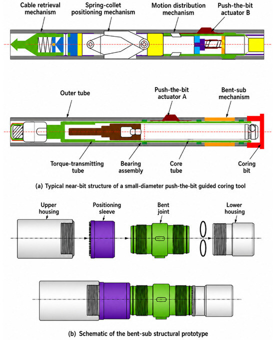
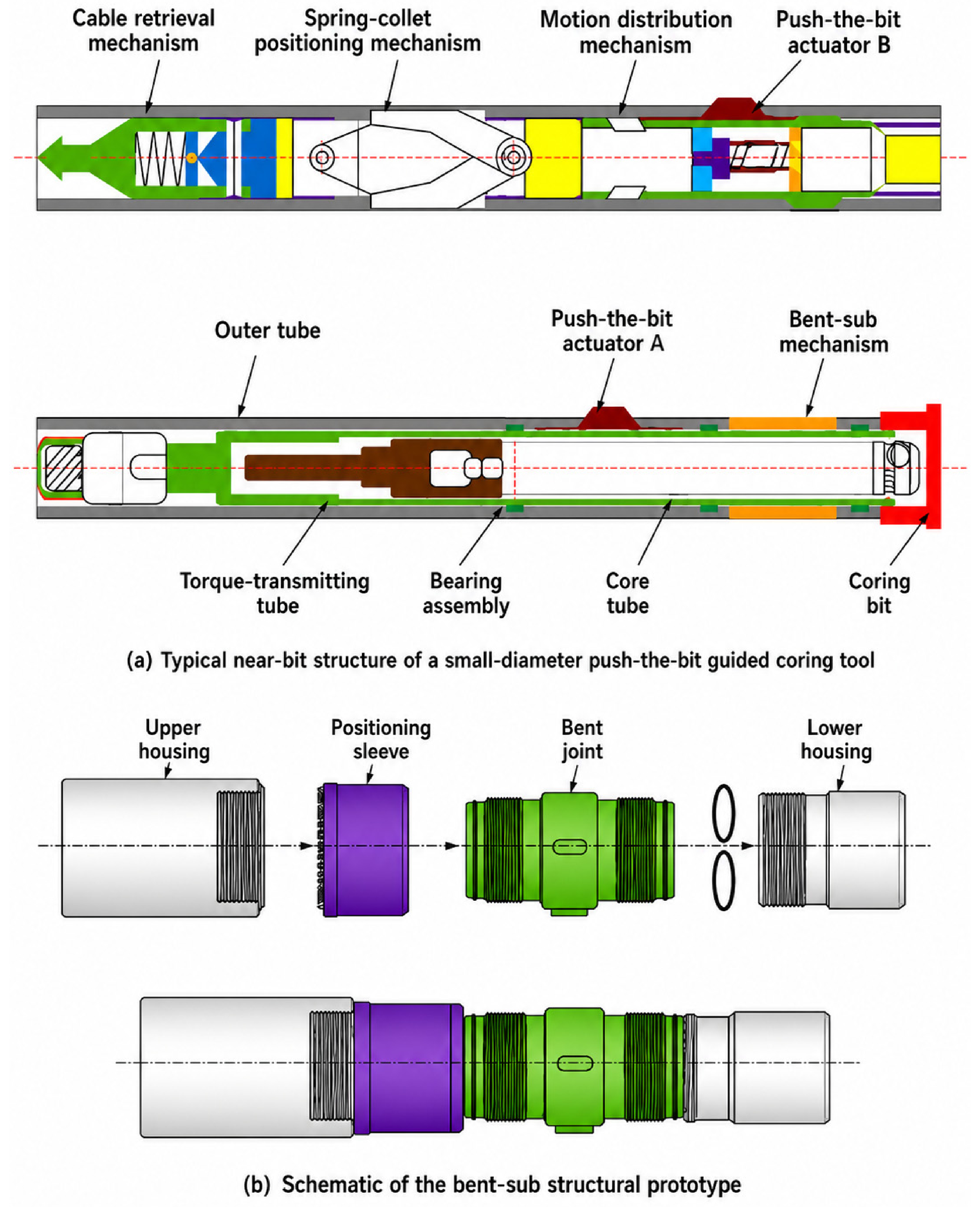
This study considers the NBA of a small-diameter push-the-bit guided coring tool. Figure 1 shows the overall tool layout and the structural prototype of the bent sub.
Figure 1.
Schematic of the typical near-bit layout and bent-sub structural prototype for the small-diameter push-the-bit guided coring tool.
As shown in Figure 1a, the NBA mainly consists of an outer tube assembly, a bent-sub unit, two push-the-bit actuators, denoted as actuator A and actuator B, and a coring bit. Figure 1b shows the internal structure of the bent sub, which includes an upper housing, a positioning sleeve, a bent joint, and a lower housing. As the main deflection component of the NBA, the bent sub affects bit performance, build-up capability, and local structural response through its geometric configuration. Three geometric parameters are considered: bent-sub length , bend angle , and distance from the bit .
In slim-hole guided coring, the annular clearance between the drilling tool and the borehole wall is small, which constrains the lateral deformation of the NBA. During steering, the assembly is subjected to the combined effects of bent-sub deflection, push-the-bit actuation forces, axial weight on bit, and borehole contact constraints. The outer tube serves as the primary load-bearing member of the NBA. Both structural strength and allowable bending deformation should be considered when evaluating the feasibility of bent-sub parameters.
To provide a consistent basis for the subsequent mechanical modeling, numerical solution, parametric analysis, and extraction of response indicators, this subsection defines the structural coordinate system, main bent-sub design variables, and reference axial layout parameters of the two push-the-bit actuators.
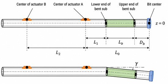
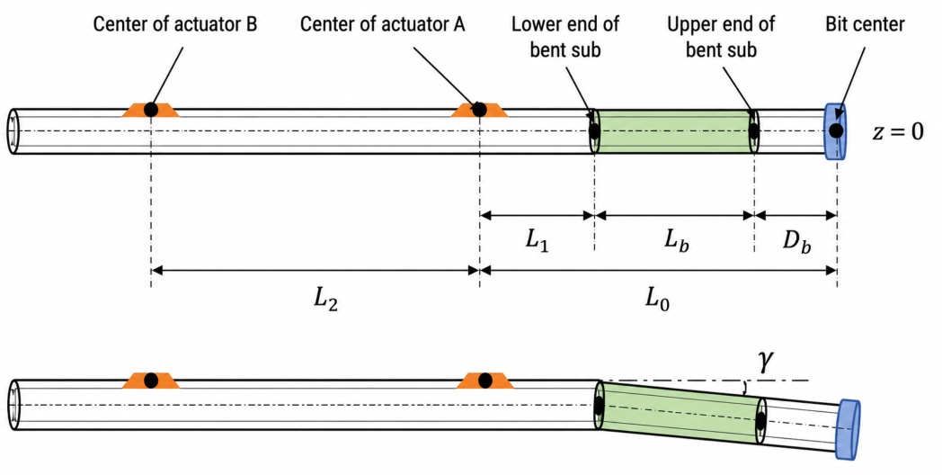
The coordinate system is established with its origin located at the bit shoulder reference section. The positive z-axis is directed upward along the longitudinal axis of the drilling tool.
Figure 2 defines the geometric meanings of the three key bent-sub design parameters, , , and , together with the axial layout of the two push-the-bit actuators and the deformation profile of the bent sub under bending conditions.
Figure 2.
Schematic of the geometric definitions of main bent-sub design parameters.
The parameters used in this study are divided into two groups: key design variables and reference axial layout parameters. The main design variables are used to analyze the parametric influence characteristics in the following sections, whereas the reference axial layout parameters are kept constant throughout the analysis. Their definitions and units are summarized in Table 1.
Table 1.
Definitions and baseline values of main bent-sub parameters.
Equation (1) defines the main bent-sub design parameters in vector form.
Equation (2) defines the reference axial layout parameters of the two push-the-bit actuators as
2.2. Mechanical Model Formulation and Solution Procedure
Based on the structural layout and parameter definitions in Section 2.1, a static bending model is established for the NBA of the small-diameter push-the-bit guided coring tool. In this model, the outer tube is regarded as the primary bending member and is idealized as an Euler–Bernoulli beam. The equivalent initial curvature of the bent sub, dual push-the-bit loads, axial weight on bit (WOB), and borehole-wall contact and friction effects are incorporated.
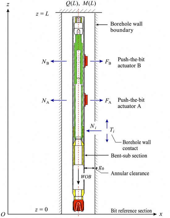
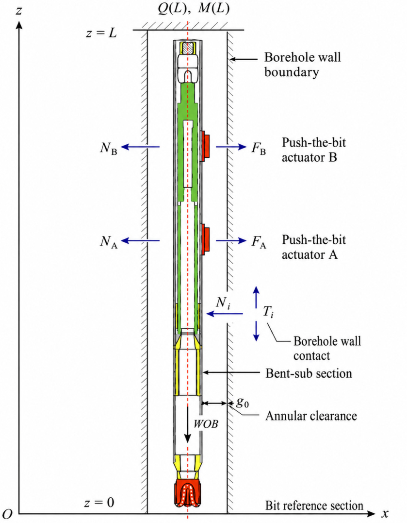
After convergence, the bit-end rotation angle, BUR, maximum combined bending–torsion equivalent stress σmax, and maximum curvature κmax are extracted as response indicators. These indicators are used to evaluate the build-up capability and local structural response of the NBA under different bent-sub parameter configurations. Figure 3 shows the modeling domain, coordinate system, and main applied loads.
Figure 3.
Schematic of the near-bit static bending model, coordinate system, and applied loads.
In Figure 3, and denote the radial push forces applied by actuators A and B, respectively. and are the corresponding borehole-wall reaction forces. and represent the normal contact force and the tangential friction force at the tool–borehole interface, respectively. WOB is the axial weight on bit, and is the radial annular clearance between the drilling tool and the borehole wall.
The following assumptions are adopted to simplify the mechanical model while retaining the dominant load-transfer mechanisms:
- (1)
- The outer tube is modeled as a linear-elastic primary load-bearing member under the small-deformation assumption. Cases exceeding the prescribed stress limit are treated as structurally infeasible.
- (2)
- The outer tube is modeled using Euler–Bernoulli beam theory, whose applicability was evaluated against the Timoshenko formulation in Section 2.3 and Table A1.
- (3)
- The active deflection of the bent sub is introduced via the equivalent initial curvature; its internal locking, threaded connections, sealing, and transmission structures are not explicitly modeled.
- (4)
- The actions of push-the-bit actuators A and B are idealized as transverse concentrated loads in the build-up plane. Their magnitudes are determined by the total push force and the load distribution coefficient.
- (5)
- The axial WOB is applied as a constant compressive load to capture its effect on the lateral bending response of the NBA.
- (6)
- The borehole wall is treated as an impenetrable boundary. The contact between the deflection tool and the borehole wall is formulated via the penalty function method, and tangential friction is incorporated following the Coulomb friction law.
- (7)
- The present model describes the quasi-static response of the NBA under steady steering conditions; dynamic drilling loads and tool vibrations are not considered.
Under these assumptions, the outer tube is modeled as a beam-column system subjected to bent-sub initial curvature, dual concentrated push loads, axial WOB, and borehole-wall contact and friction effects. Because this study focuses on the relative response variations caused by bent-sub parameter changes, the lateral displacement in the build-up plane is used to describe the bending response. Under the small-deflection assumption, the axial curvature of the tool can be approximated using Equation (3):
The moment–curvature relationship is given by Equation (4):
where is the sectional bending moment, E is the elastic modulus, I is the bending moment of inertia of the primary load-bearing outer tube,
is the tool-axis curvature, and is the lateral deflection.
The primary load-bearing outer tube has an actual outer diameter D and a con-centric circular coring channel with an actual diameter d. The beam cross-section is modeled directly as a concentric annulus rather than approximated using a fitted equivalent section. The sectional moment of inertia of the concentric annular cross-section is given by Equation (5):
where is the actual outer diameter of the primary load-bearing outer tube and is the actual diameter of the internal coring channel.
To account for the beam-column effect induced by axial WOB, the axial compressive load is defined as . Equation (6) gives the static equilibrium of the NBA under axial compression:
where is the equivalent distributed transverse load along the tool axis, including the push-the-bit actuator loads, borehole-wall contact reactions, and friction components. The term containing represents the coupling effect of axial WOB on lateral bending deformation.
To represent the active deflection of the bent sub in the beam model, the bend angle is converted into a uniform equivalent initial curvature over the active segment.
The axial range of the active segment is defined in Equation (7):
Equation (8) gives the equivalent initial curvature:
where is expressed in radians in all numerical calculations. This definition satisfies the integral condition given by Equation (9):
This ensures that the accumulated rotation over the active segment equals the designed bend angle.
Equation (10) gives the modified moment–curvature relationship within the active bent-sub segment:
Outside the active segment, no initial curvature is introduced, and Equation (4) remains valid. Equations (7)–(10) describe the equivalent initial-curvature formulation of the bent sub. In this formulation, controls the total deflection magnitude, defines the length of the active deflection segment, and determines its axial position relative to the bit.
The finite element method is used to discretize the NBA, following standard beam-element practice in BHA mechanical analysis [18]. The equivalent beam model is divided axially into two-node Euler–Bernoulli beam elements, giving total nodes. Each node has two degrees of freedom: lateral deflection and sectional rotation . The global displacement vector is written as
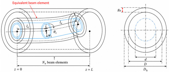
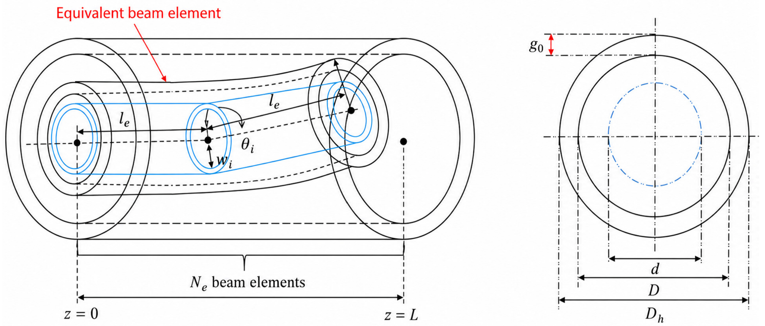
In Figure 4, is the borehole diameter, is the outer diameter of the primary load-bearing tube, is the coring-channel diameter, is the annular clearance, is the beam-element length, and is the number of beam elements. The beam elements represent the primary load-bearing outer tube of the NBA. The internal coring channel is incorporated through its actual diameter in the annular-section properties and is not modeled as an independent structural member. The borehole-wall boundary is used only for contact detection and enforcement of the radial impenetrability constraint.
Figure 4.
Schematic of equivalent beam-element discretization and nodal degrees of freedom for the NBA.
For a beam element of length , the element stiffness matrix consists of the Euler–Bernoulli bending stiffness matrix and the geometric stiffness matrix induced by axial WOB [19], expressed as the element stiffness matrix:
The first term is the elastic bending stiffness matrix, and the second term is the geometric stiffness matrix associated with the axial compressive load.
After assembling all element matrices according to the nodal degrees of freedom, the global elastic stiffness matrix and global geometric stiffness matrix are obtained. The equivalent initial curvature of the bent sub, the push-the-bit loads, and the borehole contact and friction forces are converted into equivalent nodal force vectors.
Equation (13) expresses the nonlinear static equilibrium of the NBA:
where is the global nodal displacement vector defined in Equation (11), is the equivalent nodal load vector induced by the push-the-bit actuators, is the equivalent nodal load vector associated with the bent-sub initial curvature, and is the configuration-dependent nodal force vector generated by borehole-wall contact and friction.
To complete the computational model and define the application of external loads and boundary constraints, the following boundary and loading conditions are imposed:
- (1)
- Upper-end elastic support.
The upper end of the modeling domain () is represented by an elastic support to simulate the restraining effect of the upper drill string on the NBA. The constraint relations are
where and are the equivalent lateral and rotational stiffnesses of the upper support, respectively. and denote the shear force and bending moment at the upper end section.
- (2)
- Bit-end boundary.
The bit reference section () is used as the response extraction end. No additional constraints on lateral displacement or rotation are applied at this section. The bit-end lateral displacement, sectional rotation, and internal forces are solved directly from the global equilibrium equation. The axial WOB is included in the geometric stiffness matrix as a compressive load to account for the axial–lateral bending coupling effect.
- (3)
- Push-the-bit loads.
The transverse forces from actuators A and B are defined by the total push force and a load distribution coefficient:
where is the total push-the-bit force and is the load distribution coefficient.
- (4)
- Borehole-wall contact and friction boundary.
The contact and friction boundary is formulated using the penalty function method, with tangential friction governed by the Coulomb friction law [20]. Given the single-plane lateral bending model, contact status is evaluated from the absolute lateral displacement of each node. For node i with lateral displacement , the single-sided annular clearance is , and the contact penetration is defined by Equation (16):
No contact occurs when . When , the corresponding normal contact reaction is given by Equation (17):
where is the normal contact stiffness. The contact force resists further penetration into the borehole wall, with its sign determined by the direction of .
The corresponding tangential friction force is calculated using Equation (18):
where is the borehole-wall friction coefficient. The friction force acts opposite to the direction of local relative sliding. All normal contact reactions and friction forces at contact nodes are assembled into the equivalent nodal force vector .
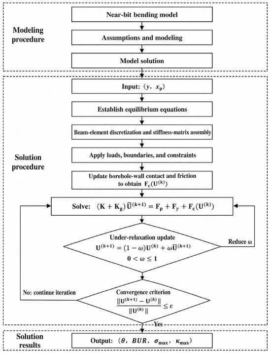
Equation (13) therefore represents a nonlinear static equilibrium equation that incorporates the equivalent initial curvature of the bent sub, WOB-induced axial–lateral coupling, push-the-bit loads, and borehole-wall contact and friction effects. Because is configuration-dependent, a contact-state iteration scheme with under-relaxation is adopted [21]. In the k-th iteration, contact nodes are first identified from the current displacement field , and the contact force is updated accordingly. With the contact state fixed, the predicted displacement is obtained using Equation (19):
To improve the numerical stability of the contact iteration, the under-relaxation update scheme is applied using Equation (20):
where is the under-relaxation coefficient. Convergence is considered achieved when the relative displacement increment between two successive iterations satisfies Equation (21):
The converged displacement field is used as the final static equilibrium solution for the NBA. The overall solution procedure is shown in Figure 5.
Figure 5.
Nonlinear static solution procedure for the NBA.
Upon convergence, four key response metrics are extracted: bit-end rotation angle , BUR, maximum equivalent stress σmax, and maximum curvature κmax.
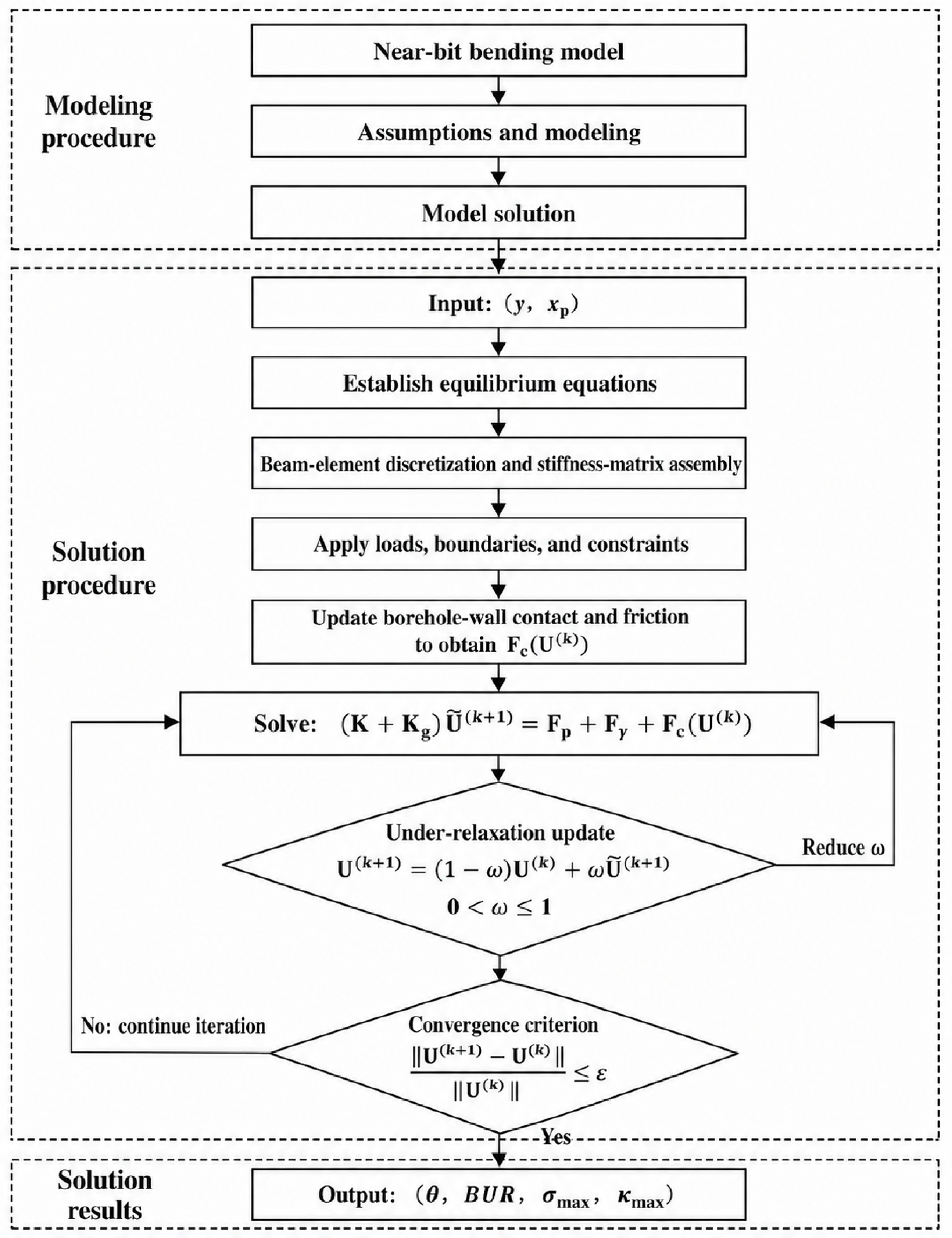
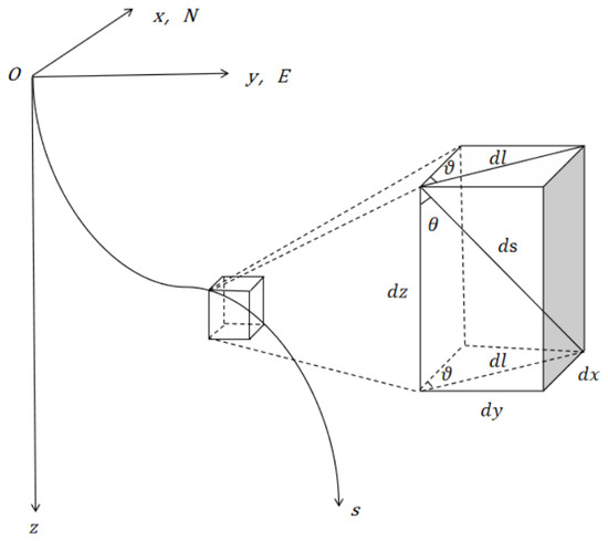
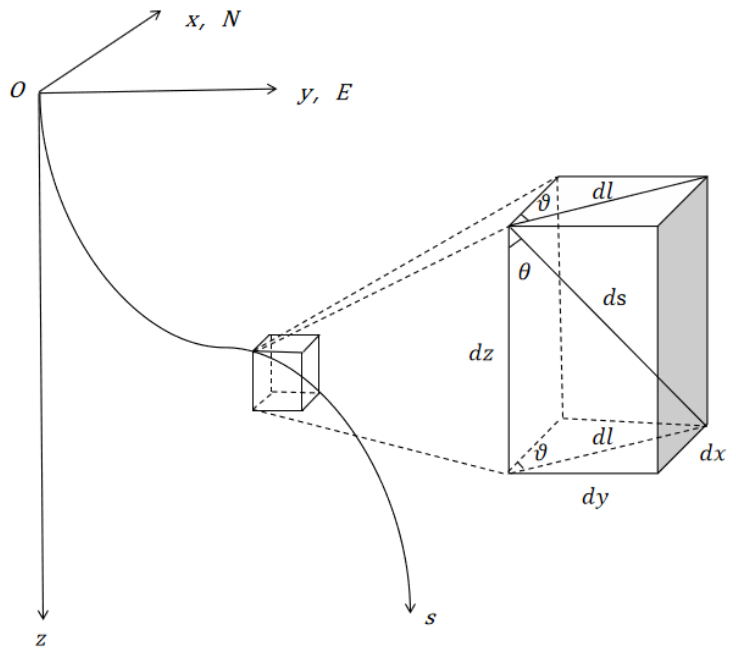
The bit-end rotation angle is obtained directly from the nodal rotation at the bit reference section. To quantify build-up capability associated with the near-bit attitude deflection, is converted into BUR using as the equivalent build-up action length:
where is in radians, is the equivalent build-up action length, and BUR is expressed in °/30 m. The geometric basis for this conversion is shown in Figure 6.
Figure 6.
Schematic of the geometric conversion between the bit inclination angle and the build-up rate.
The BUR defined by Equation (22) is an equivalent build-up capability indicator under the adopted quasi-static conditions. In actual drilling, the bit–rock interaction modifies the force and moment boundary conditions at the bit and may affect the bit-end rotation, local internal forces, and consequently the field BUR and structural response. Because these effects require a dedicated bit–rock interaction model, they are not included in the present study; the calculated BUR is therefore used only for relative comparison of bent-sub parameter schemes [22].
During build-up operations, the drilling tool is subjected to combined bending loads and drilling torques. From the fundamental bending and torsion relationships, the sectional bending stress and torsional shear stress are calculated using Equation (23):
where is the sectional bending moment, is the drilling torque, is the distance from the outer fiber of the section to the neutral axis, is the sectional moment of inertia, and is the polar moment of inertia. For a circular tubular section, .
Based on the distortion-energy theory, the combined bending–torsion equivalent stress is calculated using Equation (24):
In the present formulation, the drilling torque T enters only Equation (24) and therefore affects the combined bending–torsion equivalent stress without altering the solved lateral displacement or curvature fields.
The maximum equivalent stress over the entire modeling domain is defined by Equation (25):
Because the equivalent beam model does not resolve threaded joints, housing transitions, or actuator interfaces, σmax represents the nominal stress response of the primary load-bearing member rather than the local peak stress at these geometric discontinuities.
Curvature is derived from the converged displacement field as , and its maximum absolute value is defined as .
To constrain the structural strength and local bending severity, the allowable-stress criterion and the tool-specific curvature-control criterion are introduced in Equation (26):
where is the allowable stress and is the tool-specific curvature-control threshold. BUR, , and are selected as the core evaluation metrics for the subsequent parameter influence analysis.
2.3. Model Verification and Convergence Analysis
The influence of transverse shear deformation was evaluated using the shortest bent-sub condition, La = 0.30 m, γ = 0.8°, and Db = 0.30 m, while the remaining parameters were maintained at their baseline values. The relative differences between the Euler–Bernoulli and Timoshenko formulations were 4.00% for BUR and 2.91% for σmax (Table A1). These results support the use of Euler–Bernoulli beam theory for the present comparative parametric analysis.
A three-dimensional static finite element model was established in ANSYS Workbench 2022 R2 under baseline conditions. The geometry, material properties, loads, boundary conditions, and tool-borehole contact settings were consistent with those of the beam model. The relative differences between the two models were 6.64% for BUR and 2.94% for the maximum nominal equivalent stress (Table A1), indicating reasonable agreement in the predicted global quasi-static response.
The discretization accuracy of the beam model was subsequently assessed through a mesh convergence analysis under baseline conditions [23].
The baseline bent-sub parameter vector is defined by Equation (27):
All remaining material, loading, and contact parameters were maintained at their baseline values. For each mesh density, the nonlinear contact solution was first converged according to the relative displacement-increment criterion defined in Equation (21). BUR, maximum equivalent stress and maximum curvature were then selected as the mesh convergence metrics. BUR is determined from the bit-end rotational displacement and characterizes the global deformation response, κmax is derived from the converged displacement field and characterizes the local bending response, and reflects the sectional internal-force response. The number of beam elements was progressively increased, with the relative variation between two consecutive mesh solutions calculated using Equation (28):
where and are the results obtained using two consecutive mesh densities and represents BUR, , or . Nodal contact reactions were not adopted as a separate convergence metric because, under the penalty-contact formulation, their local values are sensitive to the contact-node discretization and may be redistributed among adjacent nodes as the mesh is refined. The convergence results are summarized in Table 2.
Table 2.
Mesh convergence of the principal response metrics.
As shown in Table 2, the response metrics varied noticeably for coarse meshes and gradually stabilized with mesh refinement. When was increased from 120 to 140, the relative variations in BUR, , and were 0.0193%, 1.2659%, and 1.2675%, respectively. Further refinement to 160 elements produced variations of 0.4919%, 1.1544%, and 1.1541%, respectively. Because the variations remained within 1.27% when the mesh was refined beyond 120 elements, was retained for the subsequent parametric analyses by balancing numerical accuracy and computational efficiency.
Together, the beam-formulation comparison, commercial finite element comparison, and mesh convergence analysis support the reliability of the model for global quasi-static parametric evaluation.
2.4. Baseline Conditions and Parameter Ranges
To ensure the comparability of parametric analysis results, this study adopted unified baseline conditions and a control-variable approach. For each calculation, only one key design variable was varied, while all other parameters were held at their baseline values.
Material properties were selected based on widely accepted values for alloy structural steel [24], and the allowable stress was determined by comprehensively accounting for the material strength, safety factor, and the connection and contact conditions of the small-diameter drilling tool [25]. The key baseline parameters are summarized in Table 3. The literature-based friction coefficient [26,27], WOB = 12 kN, and drilling torque kN·m were adopted as baseline conditions, and their effects, together with that of the borehole diameter, were evaluated, as shown in Appendix A (Table A2). The bend angle is expressed in degrees in all tables and figures but was converted to radians during numerical computation.
Table 3.
Main baseline parameters.
For quenched-and-tempered 42CrMo4 steel, the reference minimum yield strength is 650 MPa for a ruling-section size of 40–100 mm [28]. Accordingly, MPa was adopted as a conservative strength-screening limit. Independently, 0.07 is defined as a tool-specific curvature-control threshold, corresponding to a minimum local curvature radius of 14.29 m and comparable in magnitude to the 15 m severe-curvature condition reported for a 73 mm diameter slim drilling tool [29]. Because local tool-axis curvature differs from wellbore trajectory curvature, this value was used only for preliminary screening and did not replace the stress criterion.
The discrete value scheme for the three core design variables is summarized in Table 4.
Table 4.
Discrete value scheme for the core design variables.
The parameters in Table 4 were analyzed using a control-variable approach to isolate their individual quasi-static effects. For each case, only one variable was modified, while all other parameters remained at their baseline values. This analysis was intended for mechanism identification and preliminary parameter screening rather than coupled-parameter optimization. The nonlinear static solution procedure established in Section 2.2 was applied to each case, and the bit-end rotation angle, BUR, σmax, and were extracted upon convergence.
3. Results
Based on the static bending model established in Section 2, a parametric analysis was performed using a control-variable approach to evaluate the effects of bent-sub parameters on build-up capability and structural response. In each calculation case, only one parameter was varied, while all other parameters were kept at their baseline values. In addition to the overall variations in BUR, σmax, and κmax, the axial distributions of lateral displacement, curvature, and borehole-wall contact reaction were also analyzed to explain the corresponding deformation and load-transfer characteristics.
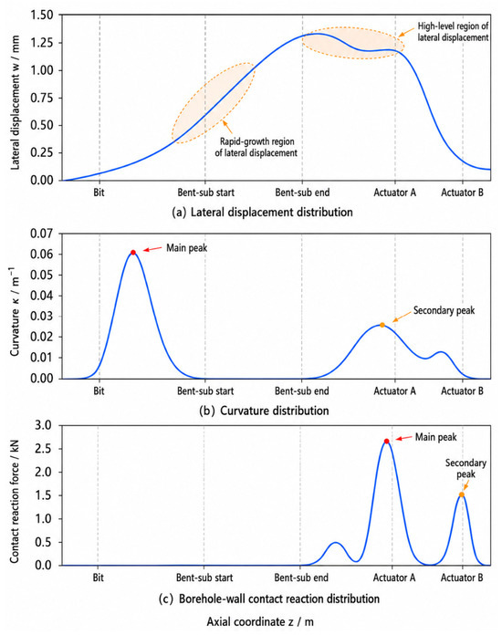
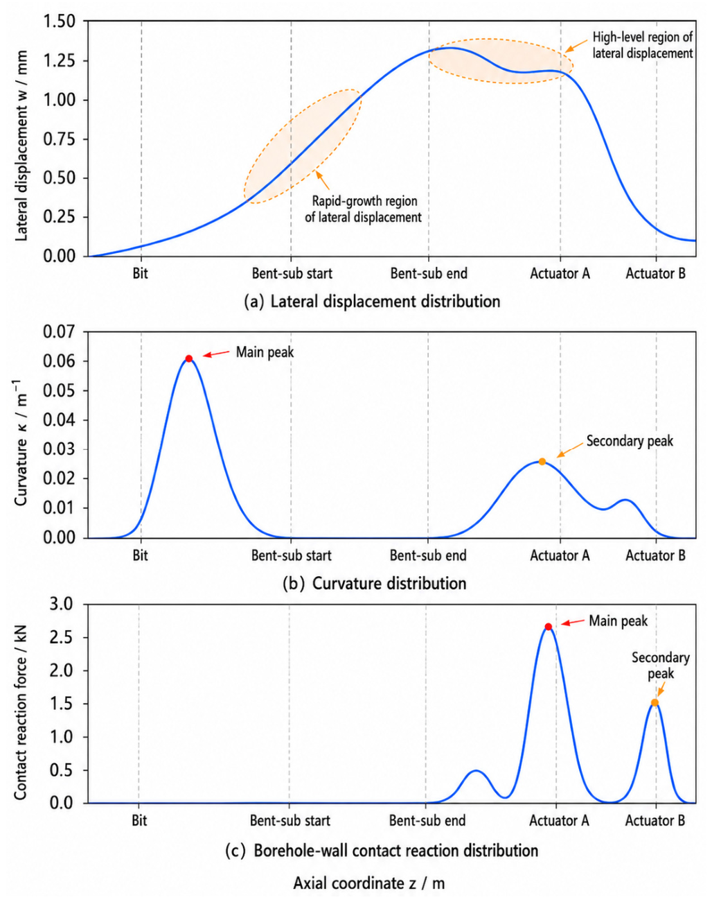
To provide a unified reference for subsequent parameter comparisons, Figure 7 presents the axial profiles of lateral displacement, curvature, and borehole-wall contact reaction under baseline conditions. Lateral displacement (Figure 7a) increases gradually from the bit end, accelerates past the bent-sub onset, peaks between the bent-sub end and actuator A, and then declines toward actuator B. Curvature (Figure 7b) is dominated by a primary peak between the bit and the bent-sub onset, with a secondary peak near actuator A and minor fluctuations between the two actuators, indicating that the most severe bending occurs in the forward near-bit section. Contact reaction (Figure 7c) concentrates around the two actuators, with a higher peak at actuator A.
Figure 7.
Baseline response distributions along the NBA.
These results indicate that the baseline response is governed by the combined action of bent-sub deflection, push-the-bit loading, and borehole-wall constraints. The baseline conditions provide a consistent reference for the subsequent parametric analysis.
- (1)
- Effect of Bent-sub Length on Build-up Capability and Structural Response
The effect of the bent-sub length was analyzed by varying while keeping the bend angle and the distance from the bit 0.30 m unchanged. All other material, loading, and boundary parameters were kept consistent with the baseline values in Table 3 and Table 4. The variation range and step size of are listed in Table 4, and the calculation results are shown in Figure 8.
Figure 8.
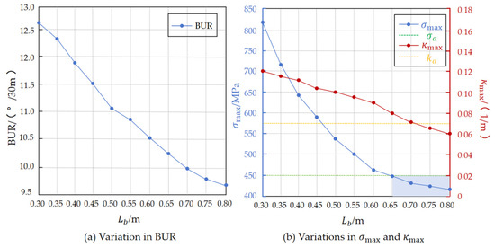
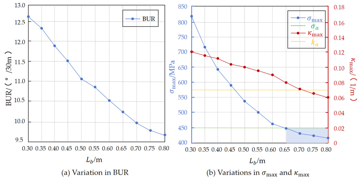
Effect of bent-sub length on build-up capability and structural response. (a) Variation in BUR; (b) Variations in combined bending–torsion equivalent stress and maximum curvature. The blue shaded area denotes the parameter region beyond the allowable structural safety limit.
As shown in Figure 8a, BUR decreases monotonically with increasing . When increases from m to m, BUR decreases from /30 m to /30 m, corresponding to a reduction of approximately 22.6%. This indicates that, within the investigated range, a shorter bent sub provides stronger build-up capability.
Figure 8b shows the variations in maximum equivalent stress and maximum curvature with . The allowable stress and curvature-control threshold are also plotted as constraint limits. As increases, both σmax and κmax decrease. Specifically, σmax decreases from approximately 820 MPa to below the allowable-stress limit, while κmax decreases from approximately 0.12 to 0.06 . The case with 820 MPa exceeds both the allowable-stress screening limit and the reference yield strength and is therefore treated only as a structurally infeasible parameter scheme; it should not be interpreted as an accurate post-yield stress prediction. The rates of decrease in both indicators gradually diminish as increases. For a fixed bend angle, increasing reduces the equivalent initial curvature and distributes the prescribed rotation over a longer segment. This reduces the local curvature and bending-moment concentrations, thereby lowering the bending component of the maximum equivalent stress, while the torsional component remains nearly unchanged because the drilling torque is fixed.
Considering the curvature constraint alone, should be greater than approximately 0.55 m, giving a feasible range of 0.55–0.80 m. Considering the strength constraint alone, should be greater than approximately 0.65 m, giving a feasible range of 0.65–0.80 m. Since both structural constraints must be satisfied simultaneously, the final feasible range of bent-sub length is 0.65–0.80 m.
The results show that bent-sub length has opposing effects on build-up capability and structural safety. Reducing improves build-up capability while local stress and curvature increase. Increasing enhances structural safety at the cost of reduced steering performance.
- (2)
- Effect of bend angle on build-up capability and structural response
The influence of the bend angle was examined by varying only , while all other parameters were kept unchanged. The variation range and step size of are listed in Table 4, and the results are shown in Figure 9.
Figure 9.
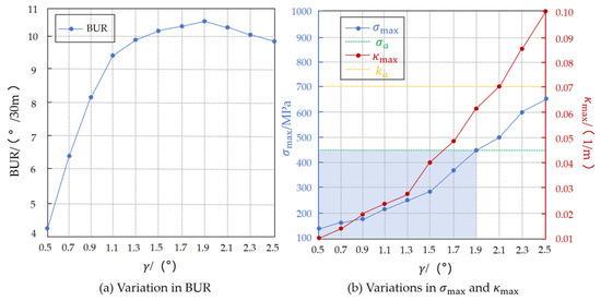
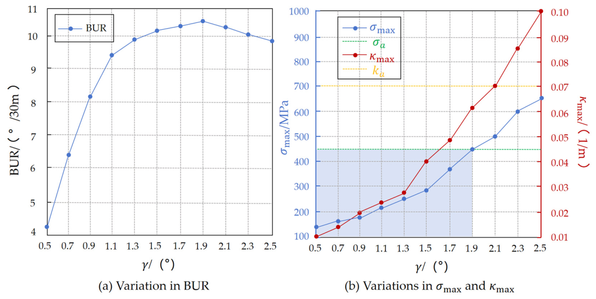
Effect of bend angle on build-up capability and structural response. (a) Variation in BUR; (b) Variations in combined bending-torsion equivalent stress and maximum curvature. The blue shaded area denotes the parameter region beyond the allowable structural safety limit.
As shown in Figure 9a, BUR increases significantly with increasing , and the rate of increase gradually decreases. When increases from to , BUR increases from m to m. After exceeds approximately , the slope of the BUR curve decreases, indicating that the marginal improvement in build-up capability becomes weaker as the bend angle continues to increase.
Figure 9b shows the variations in the equivalent stress and maximum curvature with . Both indicators increase approximately linearly with increasing . Specifically, increases from 140 MPa to 650 MPa, and increases from 0.01 to 0.10 .
The results indicate that increasing the bend angle enhances build-up capability but also amplifies local stress and bending deformation. The stress criterion limits to , whereas the curvature criterion permits values up to ; their intersection therefore gives a structurally feasible range of 0.5°∼1.9°. To define a reproducible performance lower bound, BUR was normalized by its maximum value within this feasible range. Using a 90% BUR-retention criterion, the normalized values at and are approximately 0.89 and 0.94, respectively. Thus, is the first investigated angle satisfying the performance criterion, giving a recommended engineering range of 1.3°–1.9°.
Increasing improves build-up capability but simultaneously increases the local stress and curvature responses. Moreover, the marginal improvement in BUR decreases at larger bend angles, while the structural penalty continues to increase.
- (3)
- Effect of Distance from the Bit on Build-up Capability and Structural Response
The effect of the distance from the bit on build-up capability and structural response was investigated by varying independently, with all other parameters fixed. Its variation range and step size are given in Table 4, and the results are shown in Figure 10.
Figure 10.
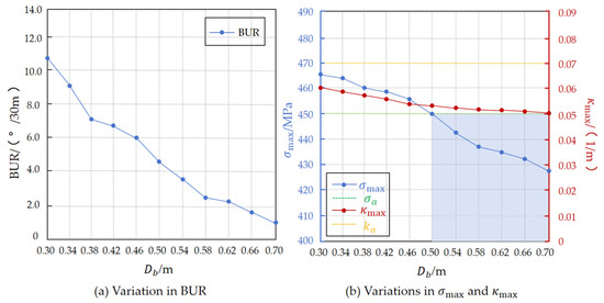
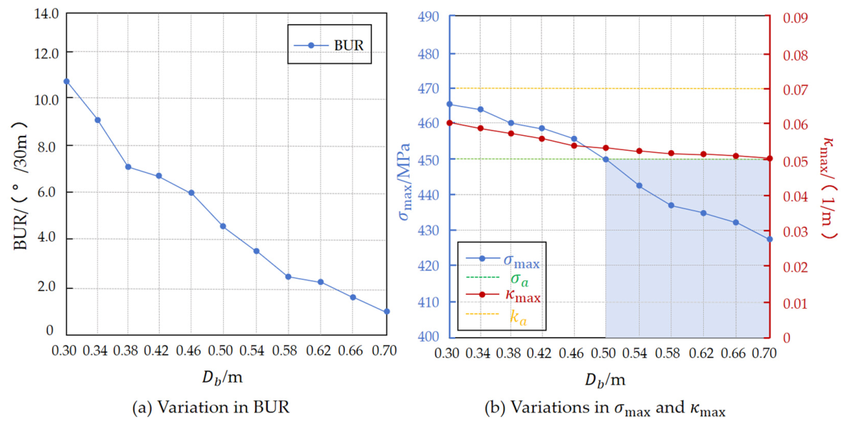
Effect of distance from the bit on build-up capability and structural response. (a) Variation in BUR; (b) Variations in combined bending-torsion equivalent stress and maximum curvature. The blue shaded area denotes the parameter region beyond the allowable structural safety limit.
Figure 10a shows that BUR decreases sharply with increasing , from /30 m at = 0.30 m to /30 m at = 0.70 m. This result confirms that moving the bent sub farther from the bit substantially reduces the build-up capability.
By contrast, Figure 10b shows that decreases from 465 MPa to 428 MPa, while κmax decrease only slightly as increases. Thus, the changes in the two structural-response indicators are considerably smaller than the change in BUR. Quantitatively, BUR decreases by 87.9%, whereas decreases by only approximately 8.0%. This contrast arises because BUR is governed by the bit-end rotation and is therefore highly sensitive to the rotation-transmission path, whereas is governed by the peak local bending–torsion load combination, whose magnitude changes only slightly as varies.
The curvature constraint is satisfied over the entire investigated range of m, whereas the strength constraint requires m. Accordingly, the simultaneous feasible interval is m, with its lower bound governed by the strength constraint.
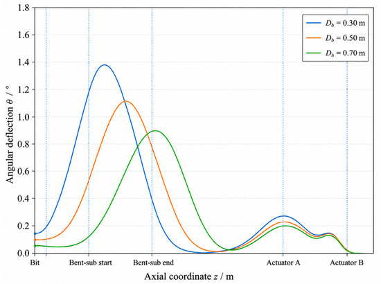
Figure 11 further illustrates the rotation-transmission mechanism associated with . As increases, the peak angular-deflection position shifts farther from the bit, while the angular deflection retained at the bit decreases markedly. This indicates greater redistribution of the bent-sub-induced rotation along the intervening segment before it reaches the bit, thereby reducing the bit-end rotation and BUR [30].
Figure 11.
Near-bit angular-deflection transmission characteristics for different bent-sub distances from the bit.
Overall, has asymmetric effects: reducing drastically improves build-up capability but erodes the structural safety margin, while increasing yields only marginal structural benefits at the cost of severely weakened steering performance.
Beyond the bent-sub design variables, the robustness of the baseline response to operating and borehole conditions was further evaluated through one-factor calculations (Table A2). Variations in the friction coefficient and WOB produced maximum absolute changes below 0.08% in the three response indicators, whereas drilling torque affected only σmax, with a maximum change of 0.51%. By contrast, borehole diameter caused maximum absolute changes of 29.56% in BUR, 7.93% in σmax, and 10.23% in , indicating that the predicted response is substantially more sensitive to borehole clearance than to the other operating parameters examined.
4. Discussion
The three geometric parameters affect tool response through distinct mechanical mechanisms. The distance from the bit mainly controls the transmission of bent-sub deflection to the bit and has the dominant effect on BUR. The bend angle determines the magnitude of active deflection, thereby increasing both build-up capability and local structural response. The bent-sub length modulates the axial distribution of bending deformation and serves as a balancing factor between steering performance and structural safety. These results indicate that bent-sub design should not aim to achieve maximum BUR in isolation. Such a design must consider build-up performance requirements, strength limits, and deformation constraints. For engineering screening, structurally infeasible schemes are first eliminated using the stress and curvature criteria, after which the remaining schemes are evaluated using the normalized BUR-retention criterion. Interactions among , , and were not considered in the present single-factor analysis; therefore, the reported ranges represent baseline-condition engineering recommendations rather than globally optimal parameter combinations.
The present model is intended for quasi-static comparison and preliminary screening under the specified geometry, loading, contact, and structural-constraint conditions. Dynamic drilling effects and bit–rock interaction are not explicitly considered, and the equivalent beam model does not resolve local stress concentrations or plastic deformation at threaded joints, actuator interfaces, or other geometric discontinuities. Therefore, the calculated BUR and should be interpreted as comparative indicators rather than direct field BUR or local peak-stress values. Although the commercial finite element comparison supports the predicted global quasi-static response under baseline conditions, the recommended ranges have not been validated through full-scale experiments or field drilling and should therefore be regarded as baseline-condition engineering recommendations. For substantially different borehole diameters or operating loads, the feasible ranges should be recalculated, particularly because the supplementary analysis identifies borehole clearance as the dominant condition-dependent factor. Application to different formations requires a formation-dependent bit–rock interaction model and corresponding experimental or field calibration.
Future work will incorporate bit–rock interaction and drill-string dynamics using dynamic finite element formulations [31] and will validate the model through laboratory and field tests. A multi-parameter optimization framework considering build-up capability and structural constraints will also be developed [32].
5. Conclusions
This study established a static near-bit bending model for small-diameter push-the-bit guided coring tools with an internal coring channel. The model incorporated the equivalent initial curvature of the bent sub, dual push-the-bit loads, axial WOB, and borehole-wall contact and friction effects. BUR, maximum equivalent stress, and maximum curvature were adopted as evaluation metrics to investigate the effects of , , and .
- (1)
- The bent-sub length has opposing effects on build-up capability and structural safety. As increases from 0.30 m to 0.80 m, BUR decreases from m to m, while both σmax and κmax decline. Considering strength and curvature constraints, the recommended range for is 0.65–0.80 m.
- (2)
- Increasing the bend angle improves build-up capability but amplifies the local structural response. As increases from to , BUR increases from m to m, while both σmax and increase monotonically. The stress and curvature criteria give a structurally feasible range of –, and the normalized BUR-retention criterion further narrows the recommended engineering range to –.
- (3)
- The distance from the bit has the strongest influence on build-up capability, with a relatively minimal effect on the structural response. Increasing reduces the transmission efficiency of bent-sub deflection toward the bit, leading to a significant decrease in BUR. Considering both build-up capability and structural constraints, the recommended range for is 0.50–0.70 m.
The results show that bent-sub parameter design for small-diameter push-the-bit guided coring tools must consider build-up capability and structural safety. The proposed modeling and parametric analysis method provides a quantitative basis for bent-sub structural design and parameter selection and provides a reference framework for further multi-parameter optimization of near-bit guided coring assemblies. Further prototype testing and field validation are required before the recommended ranges are directly applied to operational tool design.
Author Contributions
Conceptualization, P.W. and L.W.; methodology, P.W. and Y.H.; software, P.W.; validation, L.W., Y.Z., P.W. and L.H.; formal analysis, P.W.; investigation, Y.H. and L.H.; resources, L.W.; data curation, Y.Z. and Y.Q.; writing—original draft preparation, P.W. and Y.Z.; writing—review and editing, L.W. and Y.H.; visualization, Y.Q.; supervision, Y.H.; project administration, L.W.; funding acquisition, Y.H. All authors have read and agreed to the published version of the manuscript.
Funding
This research was funded by the National Natural Science Foundation of China, grant number 42572293, and the Deep Earth Probe and Mineral Resource Exploration—National Science and Technology Major Project, grant number 2024ZD1003100.
Data Availability Statement
The original contributions presented in this study are included in the article. Further inquiries can be directed to the corresponding author.
Conflicts of Interest
The authors declare no conflicts of interest.
Appendix A
Supplementary Model Verification and Sensitivity Analysis.
Table A1.
Verification of beam-formulation applicability and global model accuracy.
Table A2.
Sensitivity of the baseline response to operating and borehole conditions.
References
- Ma, T.; Chen, P.; Zhao, J. Overview on vertical and directional drilling technologies for the exploration and exploitation of deep petroleum resources. Geomech. Geophys. Geo-Energy Geo-Resour. 2016, 2, 365–395. [Google Scholar] [CrossRef]
- Wang, Y.; Li, X.; Ma, Y.; Shi, S.; Zhou, Q.; Chou, J.; Chen, J. Design and experiments of directional core drilling tool. Appl. Sci. 2025, 15, 11612. [Google Scholar] [CrossRef]
- Schaaf, S.; Mallary, C.R.; Pafitis, D. Point-the-bit rotary steerable system: Theory and field results. In Proceedings of the SPE Annual Technical Conference and Exhibition, Dallas, TX, USA, 1–4 October 2000. [Google Scholar] [CrossRef]
- Panayirci, H.M.; Brands, S.; Houette, O. Selection of optimum bottom hole assembly configuration using steering prediction modeling. J. Nat. Gas Sci. Eng. 2015, 27, 757–762. [Google Scholar] [CrossRef]
- Wang, H.; Guan, Z.C.; Shi, Y.C.; Liu, Y.W.; Liang, D.Y. Study on build-up rate of push-the-bit rotary steerable bottom hole assembly. J. Appl. Sci. Eng. 2017, 20, 401–408. [Google Scholar] [CrossRef]
- Huang, W.; Wang, G.; Gao, D. A method for predicting the build-up rate of ‘push-the-bit’ rotary steering system. Nat. Gas Ind. B 2021, 8, 622–627. [Google Scholar] [CrossRef]
- Shi, Y.; Teng, Z.; Guan, Z.; Bai, J.; Lü, W.; Liao, H.; Xu, Y.; Liu, Y. A powerful build-up rate (BUR) prediction method for the static push-the-bit rotary steerable system (RSS). Energies 2020, 13, 4847. [Google Scholar] [CrossRef]
- Chen, T.; Liu, G.; He, X.; Li, J.; Wang, W. Calculation method of the build-up rate of the internal push point-the-bit rotary steering tool. Geoenergy Sci. Eng. 2023, 230, 212177. [Google Scholar] [CrossRef]
- Nagaraj, M.; Kumar, A.J.P.; Ezilarasan, C.; Betala, R. Finite element modeling in drilling of Nimonic C-263 alloy using Deform-3D. Comput. Model. Eng. Sci. 2019, 118, 679–692. [Google Scholar] [CrossRef]
- Liu, H.; Ma, T.; Chen, P.; Wang, X.; Wang, X. Mechanical behaviors of bottom hole assembly with bent-housing positive displacement motor under rotary drilling. Arab. J. Sci. Eng. 2019, 44, 6029–6043. [Google Scholar] [CrossRef]
- Chen, Y.; Fu, J.; Ma, T.; Tong, A.; Guo, Z.; Wang, X. Numerical modeling of dynamic behavior and steering ability of a bottom hole assembly with a bent-housing positive displacement motor under rotary drilling conditions. Energies 2018, 11, 2568. [Google Scholar] [CrossRef]
- Deng, T.; Li, Q.; Yin, H.; Peng, H. A model-based intelligent adjustment method of toolface for bent-housing motor. Appl. Sci. 2023, 13, 7571. [Google Scholar] [CrossRef]
- Wang, H.; Guan, Z.C.; Zhao, G.S. Dynamic characteristic analysis on the bit lateral steering force of push-the-bit rotary steerable bottom hole assembly. Math. Model. Eng. 2018, 4, 201–209. [Google Scholar] [CrossRef]
- Guan, Z.C.; Wang, H.; Shi, Y.C.; Chen, W.Q.; Zhao, G.S.; Wang, J.Y.; Cao, Q. Dynamic behavior analysis of push-the-bit rotary steerable bottom hole assembly. J. Mech. Sci. Technol. 2019, 33, 1501–1511. [Google Scholar] [CrossRef]
- Li, Y.; Yu, Y.; Zhao, D.; Sun, Y.; Li, B.; Lim, C.W. Investigation on fatigue life of push-the-bit rotary steerable bottom hole assembly with random bit–rock interaction. Thin-Walled Struct. 2024, 198, 111752. [Google Scholar] [CrossRef]
- Bembenek, M.; Grydzhuk, Y.; Gadzik, B.; Ropyak, L.; Pasechko, M.; Slabyi, O.; Al-Tanakchi, A.; Pryhorovska, T. An analytical–numerical model for determining “drill string–wellbore” frictional interaction forces. Energies 2024, 17, 301. [Google Scholar] [CrossRef]
- Tengesdal, N.K.; Fotland, G.; Holden, C.; Haugen, B. Modeling of drill string dynamics in directional wells for real-time simulation. Simulation 2023, 99, 937–956. [Google Scholar] [CrossRef]
- Millheim, K.K.; Jordan, S.; Ritter, C.J. Bottom-hole assembly analysis using the finite-element method. J. Pet. Technol. 1978, 30, 265–274. [Google Scholar] [CrossRef]
- Cook, R.D.; Malkus, D.S.; Plesha, M.E.; Witt, R.J. Concepts and Applications of Finite Element Analysis, 4th ed.; John Wiley & Sons: New York, NY, USA, 2002. [Google Scholar]
- Wriggers, P. Computational Contact Mechanics, 2nd ed.; Springer: Berlin/Heidelberg, Germany, 2006. [Google Scholar] [CrossRef] [PubMed]
- Bathe, K.J. Finite Element Procedures; Prentice Hall: Englewood Cliffs, NJ, USA, 1996. [Google Scholar]
- Cunha, A., Jr.; Soize, C.; Sampaio, R. Computational modeling of the nonlinear stochastic dynamics of horizontal drillstrings. Comput. Mech. 2015, 56, 849–878. [Google Scholar] [CrossRef]
- Zienkiewicz, O.C.; Taylor, R.L.; Zhu, J.Z. The Finite Element Method: Its Basis and Fundamentals, 7th ed.; Butterworth-Heinemann: Oxford, UK, 2013. [Google Scholar]
- ASM Handbook Committee. Properties and Selection: Irons, Steels, and High-Performance Alloys. In ASM Handbook, 10th ed.; ASM International: Materials Park, OH, USA, 1990; Volume 1. [Google Scholar] [CrossRef]
- Budynas, R.G.; Nisbett, J.K. Shigley’s Mechanical Engineering Design, 10th ed.; McGraw-Hill Education: New York, NY, USA, 2015. [Google Scholar]
- Johancsik, C.A.; Friesen, D.B.; Dawson, R. Torque and drag in directional wells—Prediction and measurement. J. Pet. Technol. 1984, 36, 987–992. [Google Scholar] [CrossRef]
- Samuel, R. Friction factors: What are they for torque, drag, vibration, bottom hole assembly and transient surge/swab analyses? J. Pet. Sci. Eng. 2010, 73, 258–266. [Google Scholar] [CrossRef]
- ISO 683-2:2016; Heat-Treatable Steels, Alloy Steels and Free-Cutting Steels—Part 2: Alloy Steels for Quenching and Tempering. International Organization for Standardization: Geneva, Switzerland, 2016.
- Zhang, H.; Liu, X.; Yu, Z.; Liu, J.; Wang, C.; Feng, Q.; Meng, S.; Li, S. A case study on the passability of slim dual bend screw drills in high curvature sidetracking through slim boreholes from the Southern Ordos Basin. Sci. Rep. 2026, 16, 1721. [Google Scholar] [CrossRef] [PubMed]
- Wang, M.; Li, X.; Wang, G.; Huang, W.; Fan, Y.; Luo, W.; Zhang, J.; Zhang, J.; Shi, X. Prediction model of build rate of push-the-bit rotary steerable system. Math. Probl. Eng. 2020, 2020, 4673759. [Google Scholar] [CrossRef]
- Jung, T.J.; Jeong, Y.H.; Shin, Y. Simulation of directional drilling by dynamic finite element method. J. Mech. Sci. Technol. 2022, 36, 3239–3250. [Google Scholar] [CrossRef]
- Qin, J.; Liu, L.; Xue, L.; Chen, X.; Weng, C. A new multi-objective optimization design method for directional well trajectory based on multi-factor constraints. Appl. Sci. 2022, 12, 10722. [Google Scholar] [CrossRef]

Disclaimer/Publisher’s Note: The statements, opinions and data contained in all publications are solely those of the individual author(s) and contributor(s) and not of MDPI and/or the editor(s). MDPI and/or the editor(s) disclaim responsibility for any injury to people or property resulting from any ideas, methods, instructions or products referred to in the content. |
© 2026 by the authors. Licensee MDPI, Basel, Switzerland. This article is an open access article distributed under the terms and conditions of the Creative Commons Attribution (CC BY) license.