Article

Controller Design for AWD and eLSD Systems Using a Control Allocation Method

Department of Automotive Engineering, Korea National University of Transportation, Chungju 27469, Republic of Korea
Machines 2026, 14(8), 919; https://doi.org/10.3390/machines14080919
Submission received: 7 July 2026 / Revised: 29 July 2026 / Accepted: 7 August 2026 / Published: 10 August 2026
(This article belongs to the Topic Vehicle Dynamics and Control, 2nd Edition)

Abstract

This paper proposes an integrated control allocation method for a vehicle equipped with all-wheel drive (AWD) and an electronic limited-slip differential (eLSD). Unlike those of electric drive systems, the admissible clutch inputs of AWD and eLSD systems vary with drivetrain structure, engine torque, and vehicle operating conditions. To address this issue, a weighted least squares (WLS) control allocation framework is designed to coordinate the transfer clutch and the left/right eLSD clutches while considering physically derived input constraints. The proposed controller is evaluated using a CarSim–Simulink AWD-eLSD vehicle model under acceleration during steady-state cornering and double-lane-change maneuvers on high- and medium-friction road surfaces. The simulation results show that the proposed method improves yaw-rate tracking while maintaining small sideslip angles and bounded rear-wheel slip ratios compared with uncontrolled and maximum-eLSD-input cases. In addition, the proposed control allocation method requires substantially lower computation time than an MPC-based approach, supporting its suitability for real-time AWD and eLSD control applications.

1. Introduction

Most vehicle drivetrain systems are built with an open differential, and the 4 × 2 layout is the most common configuration. However, in some vehicles, additional mechanical components are installed within the drivetrain to enhance vehicle dynamic behavior by variably distributing drive torque between the front and rear and between the left and right sides, driven by both increased engine output resulting from technological advancements and improvements in mechanical design. One such device is the transfer case, which allows the torque to be sent to both front and rear wheels. This device enables 4 × 4 operation, helping the vehicle accelerate and maintain lateral stability even on low-friction road surfaces [1]. Another device that has recently been installed is the limited-slip differential. While an open differential has the advantage of effectively compensating for the difference in rotation between the left and right wheels, the torque distribution ratio between the left and right drive axles is fixed at 50:50. Therefore, if there is a large difference in the road’s coefficient of friction between the left and right wheels— or a difference between the left and right vertical loads—there is a possibility that some of the driving torque may be lost in the form of wheel slip, making it difficult to accelerate or escape from adverse road conditions. This limitation can be alleviated by adopting a limited-slip differential [2,3].
In the past, transfer cases and limited-slip differentials were solely mechanical. However, with advancements in electronic actuators such as motors and pumps, both devices have evolved into electronic or electrohydraulic systems. Using the actuators, clutches can be engaged or disengaged, which allows the vehicle to have immediate and variable torque distribution. Owing to these advantages, electronically actuated transfer cases and limited-slip differentials improve vehicle responses in terms of traction capability and maneuverability [4], and these devices are increasingly being installed in high-performance and luxury vehicles.
Installing these devices together in a vehicle results in a system with multiple control inputs. Therefore, the development of an integrated controller that simultaneously considers all inputs could enhance overall vehicle performance [5]. Integrated control of various chassis control systems has been widely studied in the field of vehicle dynamics. In particular, several studies have also investigated integrated controllers that regulate the desired driving torque at each wheel. Jang [6] proposed a lateral stability controller for a four-wheel independent drive electric vehicle. In that study, a yaw-moment contour line was introduced in the upper-level controller, and both driving and braking forces were applied simultaneously by the lower-level controller. Her [7] suggested a coordinated control algorithm for differential braking, front and rear traction torques and the active roll moment. Here, the upper-level controller was designed by the sliding-mode control method, and the lower-level controller was designed by the optimal distribution method, in which tire nonlinear characteristics were also considered in order to maximize performance. Cho [8] designed a unified controller using AFS and ESC systems. That study divided controller design into three areas. In the supervisory layer, the control mode was determined based on agility, maneuverability, and lateral stability aspects. In the control algorithm layer, a sliding-mode controller was designed based on a bicycle model, and the desired yaw moment and total longitudinal force was obtained to follow the desired yaw rate. In the coordination layer, the AFS and differential braking inputs that would provide the desired moment and force were determined by selecting the optimal solution that minimized the predefined cost function. Zhang [9] introduced a coordinated control strategy for integrated AFS and DYC systems. In that paper, the distributed model predictive control (DMPC) method was adopted to consider mutual coupling and constraints. Then, objective function weighting coefficients for AFS and DYC were adjusted using an RL algorithm. Liang [10] designed an integrated controller for AFS and ARS. In that study, a multi-agent system (MAS) was constructed based on DMPC, and cooperative game theory was applied to find optimal solutions.
Although the studies reviewed above have made meaningful contributions to integrated chassis control, several issues remain when the control target is a driveline system equipped with multiple clutches. First, most previous studies have focused on electric-motor-driven vehicles or conventional chassis actuators, whereas clutch-based torque distribution devices such as transfer cases and eLSDs have not been systematically considered as integrated control inputs. Second, although state constraints such as tire force limits have been widely addressed, the input constraints of clutch-based driveline systems have not been fully incorporated into the controller design. In AWD and eLSD systems, the admissible clutch inputs are determined by the mechanical structure of the driveline, the vehicle parameters, the inertial states, and the current engine torque. Therefore, explicitly considering these input constraints is essential for improving vehicle response while maintaining physically feasible actuator commands. MPC has been widely used for constrained vehicle dynamics control because it can systematically handle both state and input constraints [11,12,13,14,15,16,17,18,19]. Although MPC can provide desirable performance when the prediction model accurately represents the physical system and the constraint ranges are properly defined, the requirement of optimization using a prediction model can increase the computational load as the prediction horizon, sampling resolution, and number of inputs increase. This issue becomes particularly important for real-time implementation in vehicle electronic control units. To address this limitation, the present study adopts a control allocation method. Several methods for solving control allocation problems have been widely studied [20,21,22] and applied even in vehicle research area [23,24]. Similar to MPC, control allocation is an optimal-control-based approach, but there are important differences. In particular, control allocation is effective for overactuated systems in which the number of available control inputs is greater than the number of controlled variables. Since the AWD-eLSD system considered in this study has three clutch inputs for two representative virtual control objectives, namely, longitudinal force and yaw moment, it can be naturally formulated as an overactuated system. Moreover, control allocation can substantially reduce the computation time compared with MPC, making it a strong candidate for real-time control.
The main contributions of this study are summarized as follows. First, a planar full-car vehicle model combined with clutch-based AWD and eLSD wheel dynamics is formulated to directly represent the relationship between clutch inputs and vehicle motion. Second, a weighted least squares (WLS) control allocation method is designed for the AWD-eLSD system by systematically considering input constraints derived from the mechanical structure of the driveline and vehicle operating conditions. Finally, the effectiveness and computational efficiency of the proposed method are verified using CarSim–Simulink co-simulations under acceleration during steady-state cornering and double-lane-change maneuvers. The organization of this paper is as follows. First, the basic vehicle dynamics model used for the controller is introduced. Then, the physical mechanism of the transfer case and eLSD system will be described, including the dynamics modeling and the constraints present in the system. Next, the detailed procedure for designing control allocation for an AWD–eLSD system is explained step by step. Next, simulation scenarios for verifying the superiority of designed controller are introduced, and then simulation results and computational performance are analyzed. Finally, the conclusions and potential future work are discussed.

2. Vehicle Models

In this section, the vehicle dynamics model specifically for an AWD vehicle with an eLSD is discussed. First, the dynamic equations of three basic motion states, i.e., longitudinal velocity, lateral velocity, and yaw rate, are explained. Second, the wheel dynamics equations for a vehicle with AWD and eLSD systems are introduced in detail according to the slipping and lock-up state conditions of the clutches. This study deals with vehicles equipped with an AWD system where the main driveshaft is the rear shaft and the sub-driveshaft is the front shaft, and which are also equipped with an eLSD system installed on the rear differential gear.

2.1. Motion Dynamics

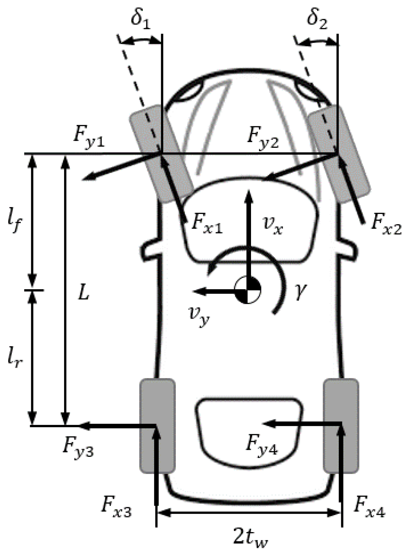
Generally, when constructing vehicle dynamics models, the bicycle model (sometimes referred to as the single-track model), which combines the left and right wheels into a single entity, is most commonly used. However, for vehicles equipped with the eLSD system discussed in this paper, since left–right drive torque distribution is possible, it is necessary to separately consider the drive forces of the left and right wheels to predict changes in vehicle dynamics based on controller actions and to design a model-based controller. Figure 1 illustrates the planar vehicle model that includes vehicle motion states and tire forces. Based on the information in Figure 1, the governing equations of motion are as follows:
m v ˙ x = F x 1 cos ( δ 1 ) + F x 2 cos ( δ 2 ) F y 1 sin ( δ 1 ) F y 2 sin ( δ 2 ) + F x 3 + F x 4 1 2 ρ a i r C d A v x 2 + m v y γ
m v ˙ y = F x 1 sin ( δ 1 ) + F x 2 sin ( δ 2 ) + F y 1 cos ( δ 1 ) + F y 2 cos ( δ 2 ) + F y 3 + F y 4 m v x γ
I z γ ˙ = l f F x 1 sin ( δ 1 ) + F x 2 sin ( δ 2 ) + F y 1 cos ( δ 1 ) + F y 2 cos ( δ 2 ) + t w F x 1 cos ( δ 1 ) + F x 2 cos ( δ 2 ) + F y 1 sin ( δ 1 ) F y 2 sin ( δ 2 ) F x 3 + F x 4 l r ( F y 3 + F y 4 )
where v x , v y , and γ are the longitudinal velocity, lateral velocity, and yaw rate, respectively, at the vehicle’s center of gravity (CG). F x i , F y i , δ i , ρ a i r , C d , m , A , t w , l f , l r , and I z are the longitudinal tire force at each wheel, lateral tire force at each wheel ( i = 1 , . . . , 4 ), wheel steer angle at each wheel ( i = 1 , 2 ), density of air, aerodynamic drag coefficient, total vehicle mass, front cross-sectional area, half of track width, distance from the front axle to the vehicle’s CG, distance from the rear axle to the vehicle’s CG, and vehicle yaw inertia, respectively.

2.2. Wheel Dynamics

2.2.1. Slipping State

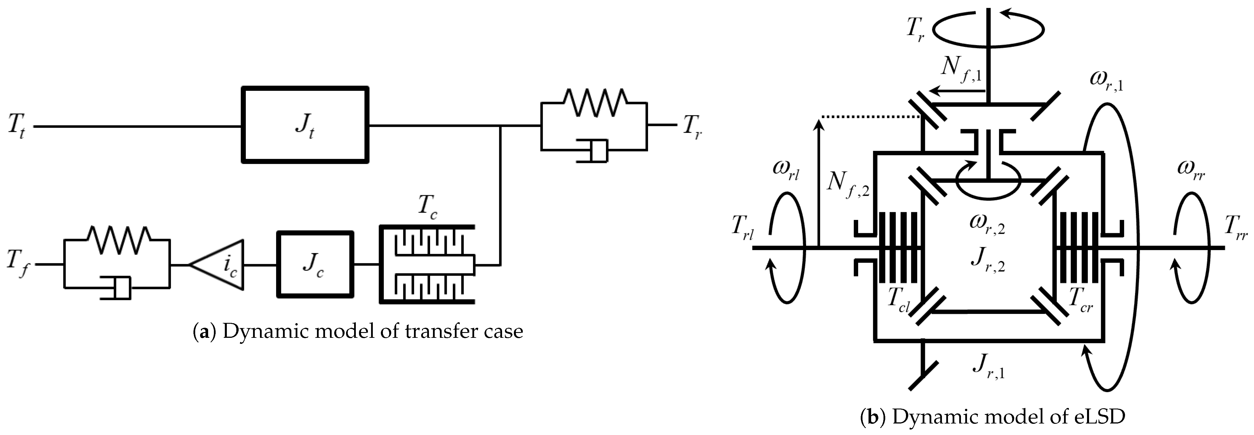
When all clutches in the transfer case and eLSD are in the slipping state, the AWD and eLSD systems can determine the amount of torque transferred to the front shaft and rear left/right drive shafts by controlling each clutch engagement force. Figure 2a shows the dynamic model of the transfer case, which is based on a rear-wheel drive (RWD) vehicle. Figure 2b shows the dynamic model of the eLSD system, which represents the type with independent left and right clutch engagement. The eLSD system is installed on the rear differential. By referring to and adapting the wheel dynamic model presented in [25], the dynamic equations of motion for the wheel of this system can be expressed as follows:
I w ω ˙ i = μ c r c F c i f 2 T b i R e F x i R e R r F z i , i = 1 , 2 I w ω ˙ 3 = T t μ c r c F c i r 2 + μ c l r c l F c l 2 μ c r r c r F c r 2 T b 3 R e F x 3 R e R r F z 3 I w ω ˙ 4 = T t μ c r c F c i r 2 μ c l r c l F c l 2 + μ c r r c r F c r 2 T b 4 R e F x 4 R e R r F z 4
where ω i , i f , i r , T t , T b i , R r , F z i , I w and R e are the wheel angular velocity at each wheel, front final reduction gear ratio, rear final reduction gear ratio, transmission output torque, braking torque at each wheel, rolling resistance at each wheel, vertical load at each wheel, wheel moment of inertia, and effective wheel radius, respectively. μ c , μ c l , μ c r , r c , r c l , r c r , F c , F c l and F c r are the friction coefficients, effective radii, and engagement force of the transfer case clutch, the left-side clutch of eLSD and the right-side clutch of eLSD, respectively. For the simulation of the AWD and eLSD systems, a model capable of reflecting the variable friction coefficient characteristics resulting from slip differences in the wet clutch was applied to enhance the reliability of the simulation [26]. In the controller design, a nominal constant value of the clutch’s coefficient of friction was used.

2.2.2. Lock-Up State

When all clutches of the transfer case and eLSD are in the lock-up state, the AWD and eLSD systems cannot actively determine the amount of torque transferred to each drive shaft. This means that the torque distribution ratio is determined not only by the clutch engagement force but also by the vehicle parameters, external conditions (e.g., the difference in the road’s coefficient of friction between the different wheels), and inertial states of vehicle (e.g., longitudinal and lateral accelerations). If all wheels are driven on roads with a homogeneous coefficient of friction, and assuming that the effective radius of all wheels is the same, the dynamic equation of motion for each wheel is expressed as follows:
I w ω ˙ i = l r L a x g h L T t 2 i f T b i R e F x i R e R r F z i , i = 1 , 2 I w ω ˙ 3 = l f L + a x g h L a y l f h g t w L T t 2 i r T b 3 R e F x 3 R e R r F z 3 I w ω ˙ 4 = l f L + a x g h L + a y l f h g t w L T t 2 i r T b 4 R e F x 4 R e R r F z 4
where h and L are the height from the ground to the vehicle’s CG and the wheelbase length, respectively.
Here, it is noteworthy that when the vehicle is driving on a homogeneous surface, the transferred torque is determined by the vertical load transfer between the front and rear axles and the lateral load transfer between the left and right wheels, determining the upper limit of clutch engagement force of each system. Regarding the upper limit of clutch engagement force, which is the control input of the controller, it will be discussed more in Section 3.

2.2.3. Mixed State of Slipping and Lock-Up

The system addressed in this study includes three independent clutches. Therefore, a complex situation may exist where a specific clutch is in a slipping state while the remaining clutches are in a lock-up state. The remaining cases of clutch engagement states of the AWD and eLSD systems, beyond the two cases introduced above, are summarized as follows.
  • Slipping state of transfer case and lock-up state of eLSD.
In this case, front and rear driving torque can be variable depending on the transfer case clutch engagement force. However, the rear left and right driving torques are determined by other parameters and inertial states, as already explained in Section 2.2.2. In the general case, the rear left and right driving torque are distributed by the weight-shifting ratio between the rear left and rear right wheels in this state, which is expressed by
I w ω ˙ i = μ c r c F c i f 2 T b i R e F x i R e R r F z i , i = 1 , 2 I w ω ˙ 3 = T t μ c r c F c g l f + a x h t w 2 a y l f h g l f + a x h t w i r 2 T b 3 R e F x 3 R e R r F z 3 I w ω ˙ 4 = T t μ c r c F c g l f + a x h t w + 2 a y l f h g l f + a x h t w i r 2 T b 4 R e F x 4 R e R r F z 4
  • Lock-up state of transfer case and slipping state of eLSD.
In this state, the amount of front and rear driving torque is calculated from vehicle parameters and values of inertial states because transfer case clutch is fully engaged. However, rear left and right driving torque can be changed depending on the left and right clutch engagement forces of the eLSD system, as expressed by
I w ω ˙ i = l r L a x g h L T t 2 i f T b i R e F x i R e R r F z i , i = 1 , 2 I w ω ˙ 3 = l f L + a x g h L T t 2 i r + μ c l r c l F c l 2 μ c r r c r F c r 2 T b 3 R e F x 3 R e R r F z 3 I w ω ˙ 4 = l f L + a x g h L T t 2 i r μ c l r c l F c l 2 + μ c r r c r F c r 2 T b 4 R e F x 4 R e R r F z 4
  • Lock-up state of transfer case with lock-up state in left clutch and slipping state in right clutch of eLSD.
Here, the amount of front and rear driving torque is the same as above in this state. Furthermore, the amount of rear left driving torque can be obtained by subtracting the rear right driving torque generated by the clutch engagement force of the right eLSD from the torque distributed to the rear wheels, which is expressed by
I w ω ˙ i = l r L a x g h L T t 2 i f T b i R e F x i R e R r F z i , i = 1 , 2 I w ω ˙ 3 = l f L + a x g h L T t i r μ c r r c r F c r T b 3 R e F x 3 R e R r F z 3 I w ω ˙ 4 = μ c r r c r F c r T b 4 R e F x 4 R e R r F z 4
  • Lock-up state of transfer case with slipping state in left clutch and lock-up state in right clutch of eLSD
In this case, since the engagement states of the left and right clutches of eLSD are the opposite of those described above, the wheel dynamics are expressed by
I w ω ˙ i = l r L a x g h L T t 2 i f T b i R e F x i R e R r F z i , i = 1 , 2 I w ω ˙ 3 = μ c l r c l F c l T b 3 R e F x 3 R e R r F z 3 I w ω ˙ 4 = l f L + a x g h L T t i r μ c l r c l F c l T b 4 R e F x 4 R e R r F z 4

3. Controller Design

Examining the wheel dynamics model of the AWD and eLSD systems (see Equation (4)) reveals that there are three independent input variables. When designing a vehicle dynamics controller, the target states are largely classified as either longitudinal or lateral states. Therefore, if the two representative target states are selected properly, with one being for the longitudinal direction and the other for the lateral direction, this system can be interpreted as an overactuated system, where the number of control actuators exceeds the number of target variables to be controlled. These insights naturally lead to the conclusion that adopting a control allocation method in this system is appropriate.

3.1. Conceptualization of Control Allocation

The principle of control allocation is briefly introduced in this subsection. Control allocation is an effective method for systems that have more control inputs than control targets when input constraints are given. This situation can be expressed mathematically as follows:
Bu ( t ) = v ( t ) u m i n u ( t ) u m a x
where v ( t ) R n is the virtual control input derived from the model, u ( t ) R m is the actual control input that is directly represented in the model, and B is the control effectiveness matrix that defines the relationship between v ( t ) and u ( t ) . Considering physical limitations from actuators, including the input’s maximum and minimum allowable values and its rate of change, input constraints are set by assigning appropriate values to u m i n and u m a x . Here, it should be noted that m is greater than n . The control allocation algorithm calculates the constrained actual input u ( t ) that satisfies (10). Among several methods for solving this mathematical problem, the WLS method was adopted because WLS is known to achieve faster computation time than other methods. Accordingly, this mathematical problem can be described by
u c a = arg min u m i n u u m a x W u u u r 2 + κ W v Bu v 2
where u r is the reference of actual input and κ , W u , and W v are weighting factors.
Therefore, u c a will be the optimally allocated input that minimizes Equation (11) with respect to u given the constraints on the input range. Actually, the determination of weighting factors is quite empirical. If reference input is highly reliable, W u can be set greater than W v . Generally, the weighting factor κ is chosen to be greater than 1 to give higher values for minimizing the second square term, which includes the desired values.

3.2. Equation Formulation

This section introduces how to determine virtual inputs among the basic motion dynamics models given in Equations (1) and (3).

3.2.1. Design of Virtual Control Inputs

By examining motion dynamics models, it can be verified that both the change in longitudinal velocity and the yaw rate are affected by the longitudinal tire forces, which are directly related to actual inputs. Therefore, two lumped virtual inputs can be designed as follows:
v 1 F x 1 cos ( δ 1 ) + F x 2 cos ( δ 2 ) v 2 l f sin ( δ 1 ) t w cos ( δ 1 ) F x 1 + l f sin ( δ 2 ) + t w cos ( δ 2 ) F x 2 + t w ( F x 3 + F x 4 )
The meaning or objective of v 1 is to maintain the desired longitudinal force using front left and right tire longitudinal forces, which are related to longitudinal stability. Furthermore, the meaning of v 2 is to maintain the desired moment using all tire longitudinal forces, which are related to lateral stability. Then, these two virtual inputs are used to enhance both longitudinal and lateral stability response simultaneously.
In order to find the control effectiveness matrix B that relates virtual inputs and real inputs, a wheel dynamics model was applied in this study. By rearranging Equation (4), each longitudinal tire force can be expressed as follows:
F x i = μ c r c F c i f 2 T b i R e R r F z i I w ω ˙ i / R e , i = 1 , 2 F x 3 = T t μ c r c F c i r 2 + μ c l r c l F c l 2 μ c r r c r F c r 2 T b 3 R e R r F z 3 I w ω ˙ 3 / R e F x 4 = T t μ c r c F c i r 2 μ c l r c l F c l 2 + μ c r r c r F c r 2 T b 4 R e R r F z 4 I w ω ˙ 4 / R e
By combining Equations (12) and (13), B can be obtained as follows:
B = μ c r c i f cos ( δ ) / R e 0 0 l f μ c r c i f sin ( δ ) / R e t w μ c l r c l / R e t w μ c r r c r / R e
Furthermore, the actual control inputs are
u = u 1 u 2 u 3 T = F c F c l F c r T
Furthermore, there is a remaining term α not related to control inputs, which is described by
α = T b 1 + T b 2 R e R r F z 1 + F z 2 I w ω ˙ 1 + ω ˙ 2 cos ( δ ) / R e T b 1 + T b 2 R e R r F z 1 + F z 2 I w ω ˙ 1 + ω ˙ 2 l f sin ( δ ) / R e + T b 3 T b 4 + R e R r F z 3 F z 4 + I w ω ˙ 3 ω ˙ 4 t w / R e
Here, it was assumed that the front left and right wheels have approximately the same steer angle, i.e., δ 1 = δ 2 = δ , for the simplification of B and for all other calculations used in control allocation algorithm.
Then, the WLS method in Equation (11) was modified as follows:
u c a = arg min u m i n u u m a x W u u u r 2 + κ W v Bu + α v 2

3.2.2. Design of Virtual Control Laws

Since virtual inputs were determined, the virtual control laws for these inputs to regulate the longitudinal velocity, yaw rate, and lateral tire forces needed to be designed. From Equations (1) and (3), by rearranging the remaining terms that are not included in virtual inputs and by substituting the desired values in physical states, the following virtual control laws can be derived:
v 1 d m v ˙ x d + F y 1 d sin ( δ 1 ) + F y 2 d sin ( δ 2 ) F x 3 d F x 4 d + 1 2 ρ a i r C d A v x d 2 m v y d γ d v 2 d I z γ ˙ d { l f cos ( δ 1 ) + t w sin ( δ 1 ) } F y 1 d { l f cos ( δ 2 ) t w sin ( δ 2 ) } F y 2 d + l r ( F y 3 d + F y 4 d ) k p ( γ γ d )
where k p is the proportional gain. However, since the desired values included in virtual control laws are calculated without accounting for their coupling effects, this may degrade the controller performance.

3.2.3. Design of Actual Input Reference

The reference value of the actual input is used to guide the WLS solution toward a feasible input when multiple solutions exist. By considering the torque distribution between front and rear, rear left and rear right that is expressed in Equation (5) as well as the desired slip ratio λ d , the following engagement force reference of each clutch was obtained:
u 1 r = l r L a x h g L T t μ c r c · min λ λ d , 1 u 2 r = sat min γ + γ p , 0 γ p · max l f L + a x h g L T t , T t μ c r c F c i r μ c l r c l a y l f h g l f + a x h t w u 3 r = sat max γ γ p , 0 γ p · max l f L + a x h g L T t , T t μ c r c F c i r μ c r r c r a y l f h g l f + a x h t w
Here, γ p is the parameter that distinguishes the longitudinal and lateral motion of vehicle for the proper operation of the proposed controller. In other words, if the absolute value of the yaw rate does not exceed a certain threshold that accounts for the vehicle’s lateral motion, the eLSD will not engage. In addition, the linearly varying value of left and right reference input of eLSD system in a range of γ p < | γ | < 2 γ p was applied in order to prevent a drastic change in their values when the yaw-rate sign changed. To maintain the same tire grip margin, which is proportional to the vertical load, the amount of torque distribution of eLSD was set based on the difference in load between the left and right sides.

3.2.4. Constraints on Actual Input

As explained in Section 2.2, slipping and lock-up states exist in the clutch system. Furthermore, the fact that their state transition condition is determined by input torque and external load implies that the input range is variable depending on current vehicle states, which highlights the necessity of using a control allocation method in this system.
Based on the clutch system’s characteristic that the maximum allowable input of each clutch is determined by vehicle parameters and inertial states, input ranges are described as follows:
0 u 1 l r L a x h g L T t μ c r c 0 u 2 max l f L + a x h g L T t , T t μ c r c F c i r μ c l r c l 0 u 3 max l f L + a x h g L T t , T t μ c r c F c i r μ c r r c r
Notably, this input range was determined without considering tire characteristics, i.e., tire non-linearity and tire–road adhesion limits.

3.2.5. Determination of Desired Values for Virtual Inputs

For the calculation of desired virtual inputs introduced in Section 3.2.1, the information of the desired values for v x , γ , F x i ( i = 3 , 4 ) and F y i ( i = 1 , , 4 ) is necessary. These are determined from the information of vehicle and tire parameters, etc. For example, the desired longitudinal tire forces can be obtained from the slip ratio and the road’s coefficient of friction μ , and the desired lateral tire forces can be obtained from the weight transfer and desired yaw rate in the following form:
F x i d = μ F z i · min ( 1 , λ λ d ) , i = 1 , , 4
F y i d = 1 cos ( δ ) F z i F z 1 + F z 2 l r L m v x γ d , i = 1 , 2 F y i d = F z i F z 3 + F z 4 l f L m v x γ d , i = 3 , 4
As for the desired value of v y , it was set to 0, which means that the controller is designed to minimize the sideslip angle. All other equations for the desired values mentioned above are introduced in [27,28].

4. Simulations

To verify the effectiveness of the proposed algorithm, simulations were conducted using CarSim, which is well known for vehicle dynamics simulation. In order to represent the mechanical characteristics of the clutch in the transfer case and the eLSD system, they were modeled using Simulink and were integrated into CarSim as an external model. A detailed explanation of the method for driveline modeling and integration of the torque transfer system for simulation is introduced in [29].
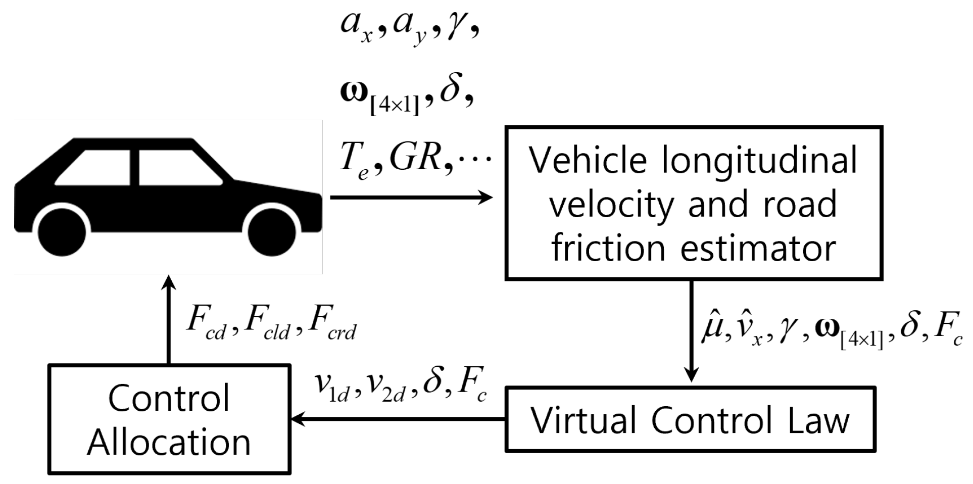
Figure 3 shows the overall structure of the designed controller. Here, it was assumed that the vehicle’s longitudinal velocity could be predicted with sufficient accuracy to be used in controller design using the results from the longitudinal velocity estimator developed in previous studies [30,31,32], which requires only in-vehicle sensors for real-time applicability. For the same reason as with the velocity estimator, it was assumed that the road friction coefficient is already known. Here, the AWD clutch input force F c is used to determine the upper limit for eLSD input, which is introduced in Equation (20). To account for the actuator bandwidth, which is one of the response characteristics of the lower-level controller, all control command values obtained from the upper-level controller were passed through a 10 Hz low-pass filter before being fed into the system as input values.
In order to verify the enhancement of responses by a vehicle that adopts the proposed controller, two simulation scenarios including acceleration input were selected. First was rapid acceleration during steady-state cornering. Second was rapid acceleration during a double lane change. In each scenario, simulations were conducted for two different coefficients of friction for the road, μ = 0.85 , 0.5 . In both scenarios, large longitudinal slip, sideslip and lateral load transfer occur in the vehicle, which provides appropriate test conditions to validate the performance of the system addressed in this study. To evaluate the performance of the proposed controller, we selected the uncontrolled case and a case where u 1 r is applied to the AWD system and the maximum input is applied to the eLSD system as comparison scenarios.
In the controller, the MATLAB/Simulink R2020a quadprog solver was used to find the local minimum of the constrained vector-valued quadratic function. The controller sampling time was set to 10 ms. Table A1 shows the vehicle specifications of the selected vehicle model, which is based on a full-size sedan. Furthermore, Table A2 presents the parameter values applied in the controller.

4.1. Rapid Acceleration During Steady-State Cornering

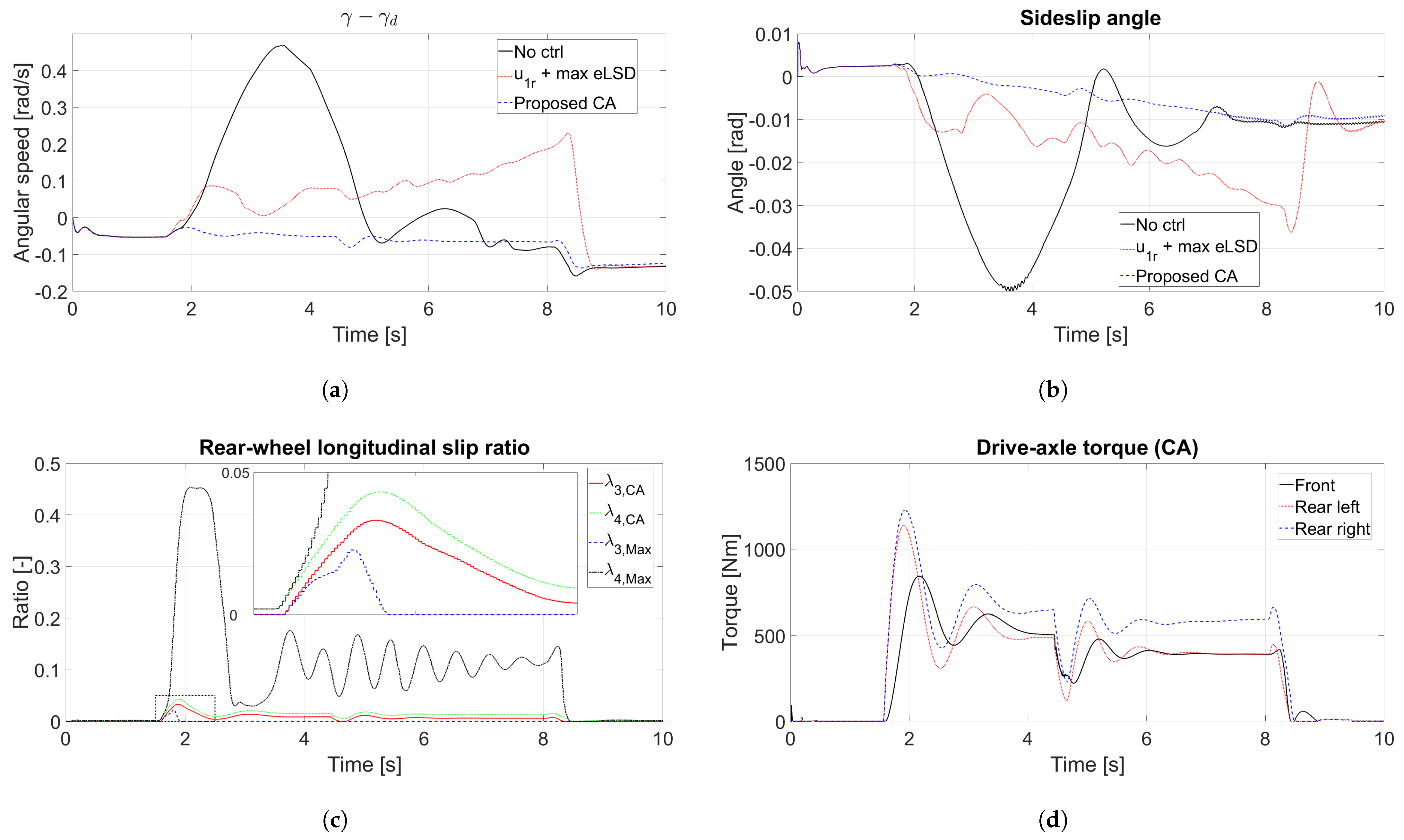
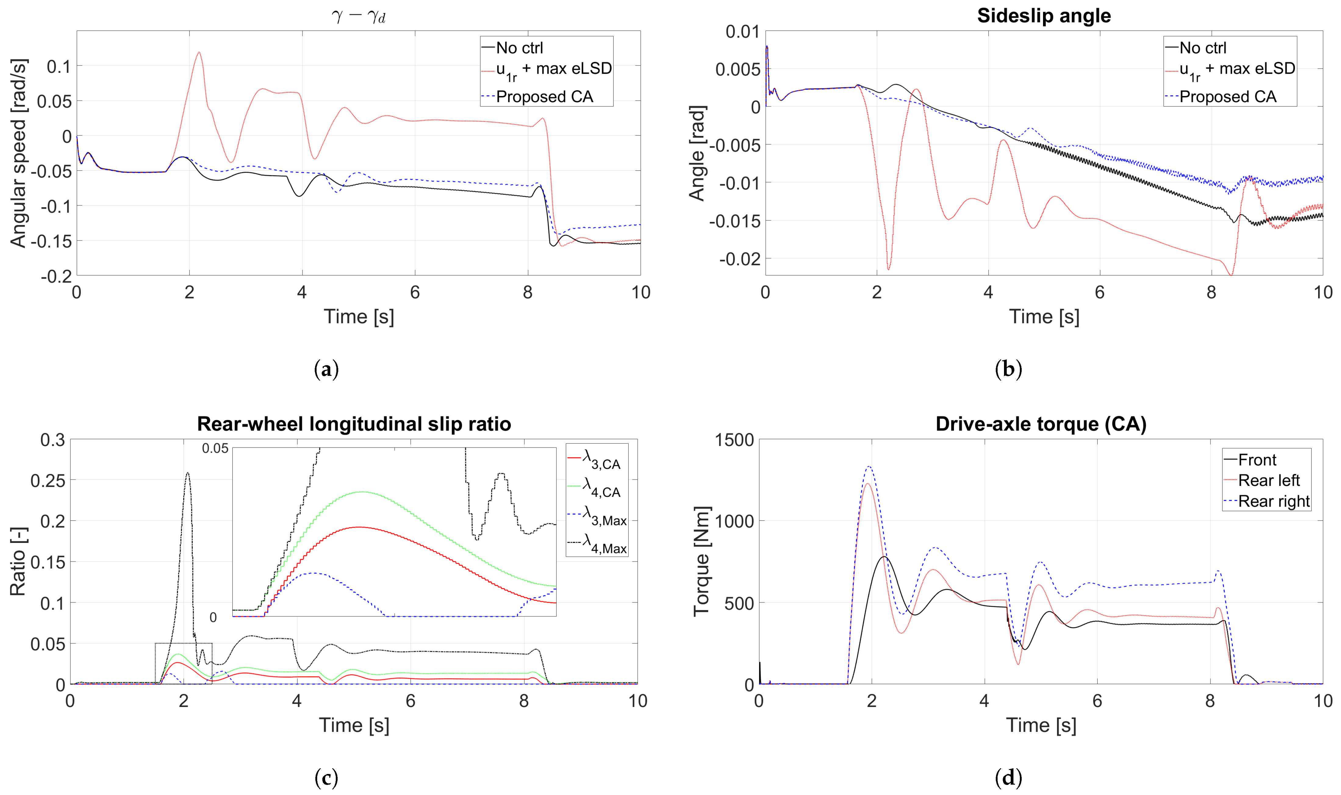
The first simulation scenario was rapid acceleration during steady-state cornering in the counterclockwise direction. The vehicle was driven on a circular road with a radius of 300 m and an initial speed of 60 km/h. Full-throttle acceleration was applied from t = 1 to t = 8   s . Figure 4 shows the results for the high-friction condition ( μ = 0.85 ). Figure 4a represents the yaw-rate error. The black solid line represents the no-control case, the red dotted line represents the case with the maximum eLSD clutch input combined with the transfer-case reference input, and the blue dashed line represents the case with the proposed controller. Here, the uncontrolled vehicle shows a negative yaw-rate error during acceleration, indicating that the actual yaw rate is lower than the desired yaw rate. This response corresponds to stable but under-responsive yaw behavior. The proposed control allocation method reduces the yaw-rate error while maintaining the vehicle in this stable response region. By contrast, the maximum eLSD input case produces an excessive yaw response, and the sign of the yaw-rate error changes intermittently. This result indicates that simply applying the maximum eLSD clutch force can generate excessive yaw moment even when sufficient tire–road friction is available. Figure 4b shows the sideslip angle. The uncontrolled vehicle exhibits a gradually increasing sideslip angle as the vehicle speed increases. The proposed controller maintains a small sideslip angle throughout the acceleration period, whereas the maximum eLSD input case produces the largest sideslip angle. This result suggests that excessive eLSD clutch engagement can reduce the lateral force margin of the rear tires and deteriorate lateral stability. Figure 4c compares the rear-wheel longitudinal slip ratios for the proposed controller and the maximum eLSD input case. The blue dashed and black dash–dot lines are the rear left and rear right wheel slip ratios for the maximum eLSD case, and the red solid and green dotted lines are the rear left and right wheel slip of the proposed controller, respectively. In the simulation, the regulation of wheel slip was definitely effective, since the vehicle longitudinal velocity information is accurate. The proposed controller keeps both rear wheels’ slip ratios below 0.05, whereas the maximum eLSD input case causes a large slip ratio at the rear right wheel, which is the outer wheel in this scenario. This result demonstrates that the proposed controller suppresses excessive rear-wheel slip while improving the yaw-rate response. Figure 4d shows the drive-axle torque distribution obtained using the proposed controller, which is exactly the amount of torque after the differential. Here, the black solid line is the amount of torque for both the front left and front right drive axles, the red dotted line is for the rear left and the blue dashed line is for the rear right drive axle, respectively. The front drive-axle torque remains smaller than the rear drive-axle torque because the rear-wheel slip ratio is below the desired slip ratio. The left–right rear torque difference increases as the yaw-rate error and lateral load transfer increase. This indicates that the proposed control allocation method adjusts the eLSD clutch forces according to the required yaw moment instead of applying unnecessary maximum clutch engagement. However, limitations of the proposed controller were also identified in this simulation. In Figure 4a,c,d, when t = 6 to t = 8   s , even after the rear drive-axle torque has stabilized following a gear shift caused by an acceleration, it can be observed that the drive torque on the rear right wheel gradually increases while that on the rear left wheel gradually decreases, which is attributed to the effect of the k p gain in the v 2 d as the yaw-rate error increases. However, despite these torque changes, the rear-wheel slip ratio remained almost unchanged. It was also observed that when the vehicle is cornering at high speeds, as the tire lateral force increases, the drive torque distribution fails to produce changes in the tire longitudinal force due to the coupling effect.
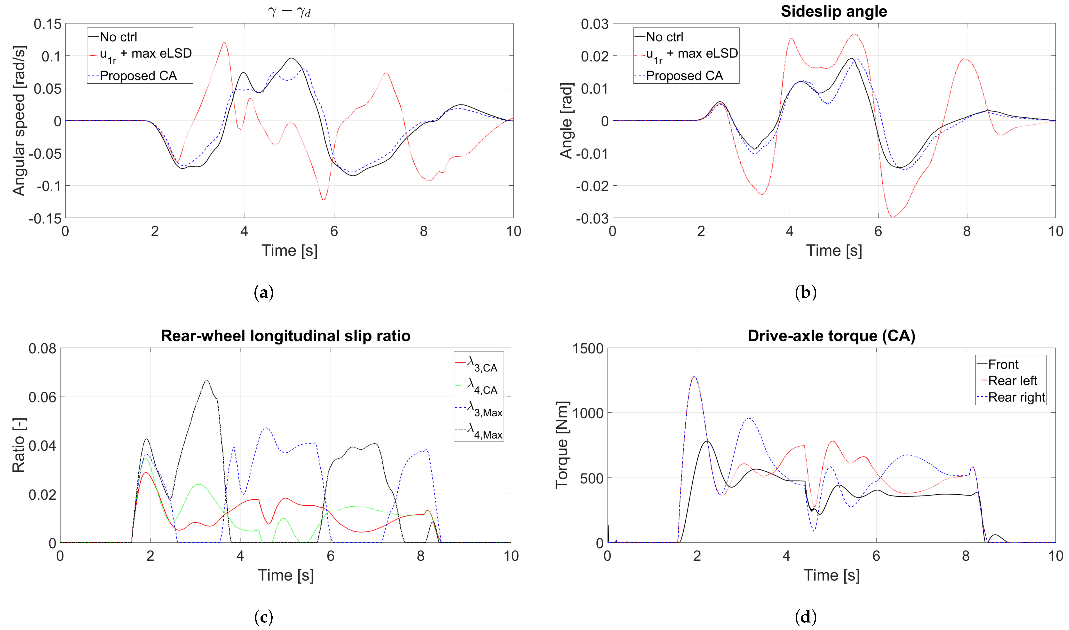
Figure 5 presents the results for the medium-friction condition ( μ = 0.5 ), which helps to predict performance on a wet asphalt road surface. All conditions except for the road’s coefficient of friction were the same as those in the high-friction scenario. Figure 5a shows the yaw-rate error. Compared with the high-friction case, the uncontrolled vehicle exhibits a much larger yaw-rate error during the initial acceleration period, particularly from t = 2 to t = 5   s . The maximum eLSD input case also shows an unstable yaw-rate response as the vehicle speed increases. Among the three cases, only the proposed controller maintains the yaw-rate error within a bounded range, with the absolute value remaining below approximately 0.1 rad/s. A similar trend is observed in the sideslip response shown in Figure 5b. The proposed controller produces the smallest sideslip angle during acceleration, and its magnitude remains close to that observed under the high-friction condition. In Figure 5c, the maximum eLSD input case generates a large rear right wheel slip during the initial acceleration period. The oscillatory slip response observed after approximately t = 3.5   s is attributed to the intervention of the ABS model in CarSim. In contrast, the proposed controller keeps the slip ratios of both rear wheels below 0.05, although a slight increase is observed compared with the high-friction condition (see the enlarged Figure in Figure 4c and Figure 5c). Figure 5d shows the torque distribution under the medium-friction condition. The front drive-axle torque increases compared with the high-friction case because the rear-wheel slip ratio becomes larger on the lower-friction surface. Nevertheless, the left–right rear torque distribution remains well regulated by the proposed controller. These results confirm that the proposed method effectively balances yaw-rate tracking and rear-wheel slip suppression during acceleration in steady-state cornering.

4.2. Rapid Acceleration During a Double Lane Change

The second simulation scenario was rapid acceleration during a double-lane-change maneuver from left to right. To increase the lateral instability of the vehicle, full-throttle acceleration was applied from t = 1   s , immediately before the lane change maneuver, to t = 8   s . The initial vehicle speed was set to 60 km/h. Figure 6 shows the results for the high-friction condition ( μ = 0.85 ). As shown in Figure 6a, the yaw-rate error in the case with the proposed controller is generally smaller than that in the uncontrolled case during most of the lane change maneuver. The uncontrolled vehicle remains stable under this high-friction condition, but its yaw-rate tracking performance is degraded during the transient steering phases. The maximum eLSD input case produces larger and more oscillatory yaw-rate error, indicating that excessive clutch engagement can deteriorate transient yaw behavior under this scenario. Figure 6b shows the sideslip angle. The proposed controller exhibits a slightly larger sideslip angle than the uncontrolled case in some time intervals, which indicates that the smallest yaw-rate error does not necessarily correspond to the smallest sideslip angle. However, the maximum absolute value of the sideslip angle remains below approximately 0.02 rad, indicating that the vehicle remains within a stable lateral motion range. In contrast, the maximum eLSD input case produces larger sideslip variations, particularly during the transient phases of the lane change. Figure 6c shows the rear-wheel longitudinal slip ratio. In this case, unlike the steady-state cornering case, the maximum eLSD input does not continuously increase the slip ratio of a single rear wheel because the required yaw moment direction changes during the lane change maneuver. Instead, the rear-wheel slip ratios switch between the left and right wheels as the lateral motion direction changes. The proposed controller suppresses this undesirable switching behavior and maintains smaller maximum rear-wheel slip ratios by continuously reallocating the left and right eLSD clutch forces according to the required yaw moment. Figure 6d confirms that the proposed controller changes the rear left–right torque distribution according to the direction of the maneuver.
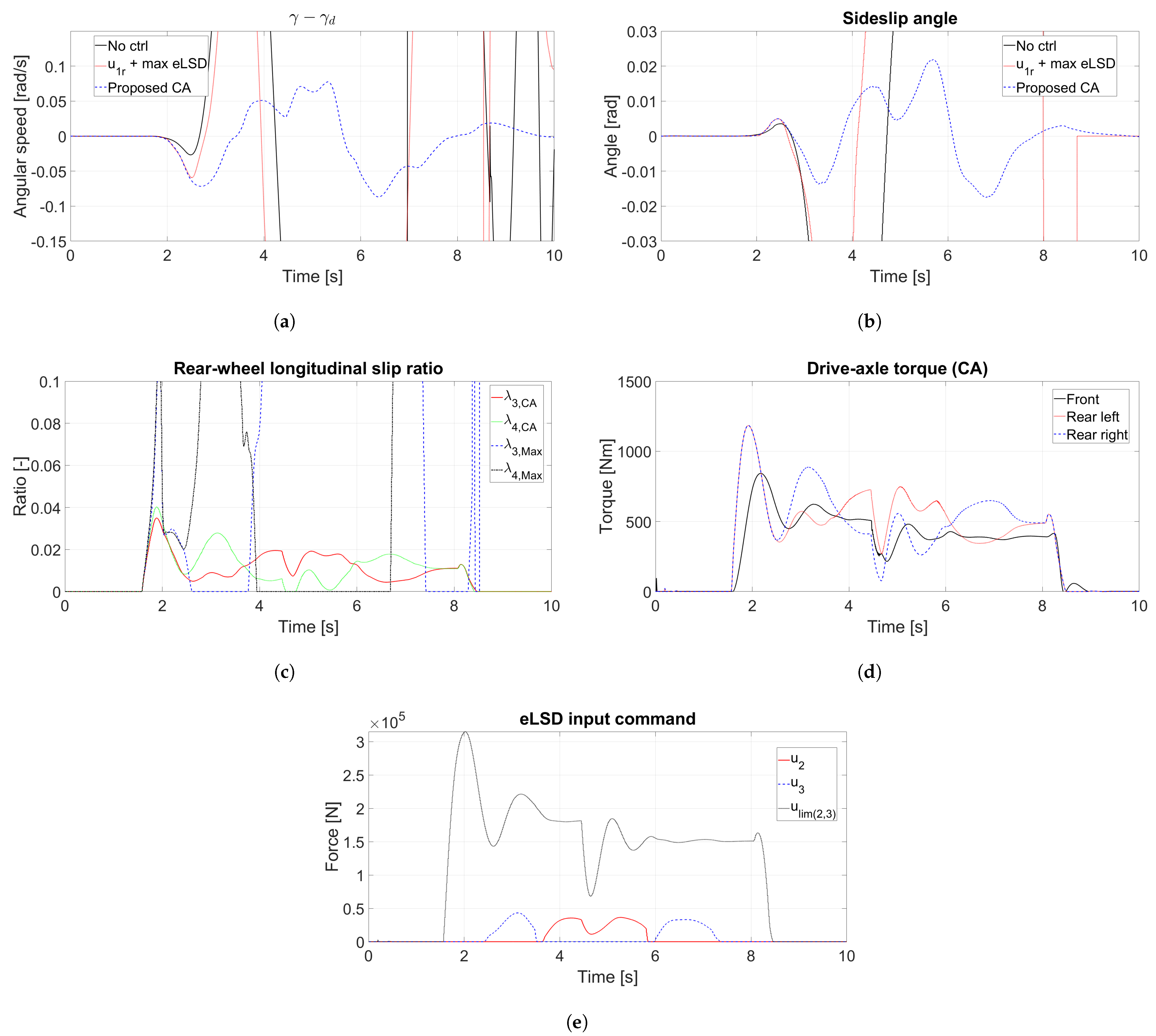
Figure 7 shows the results for the medium-friction condition ( μ = 0.5 ), which is the most severe scenario considered in this study. Under this condition, the uncontrolled vehicle and the maximum eLSD input case fail to maintain stable lane-following behavior. Their yaw-rate error, sideslip angle, and rear-wheel slip ratio rapidly increase beyond the normal range of feasible driving, indicating loss of stable vehicle response during the maneuver. By contrast, the proposed controller completes the double-lane-change maneuver while maintaining both longitudinal and lateral stability. More specifically, the proposed controller produces a bounded yaw-rate error throughout the maneuver, although a slight increase appears during the final lane-change phase around t = 6 6.5   s , as shown in Figure 6a and Figure 7a. Figure 7b shows that the sideslip angle remains within a stable range, with the maximum absolute value below approximately 0.03 rad. The local peaks become larger than those in the high-friction case, which is expected because the available tire–road friction is reduced. Figure 7c shows that the rear-wheel slip ratios remain bounded, with only a slight increase during the initial acceleration period. This behavior results from the coordinated front–rear torque distribution and left–right eLSD torque allocation. Figure 7d shows that the overall torque distribution trend is similar to that in the high-friction case, while the front drive-axle torque increases because the rear-wheel slip tendency becomes larger on the medium-friction surface. Figure 7e shows the eLSD clutch input command. It is noteworthy that eLSD input is lower than 1/4 of the input limit in all ranges except for gear shift, which implies that the proposed controller has acceptable tracking performance within stable vehicle response without causing drastic changes in left and right driving torque.
Table 1 shows the IAE and peak values of yaw-rate error. The proposed controller did not always show the best IAE value but showed the minimum peak value of yaw-rate error in all cases. The most marked benefit of the proposed controller was the improved lateral control performance in medium-friction compared with high-friction conditions.
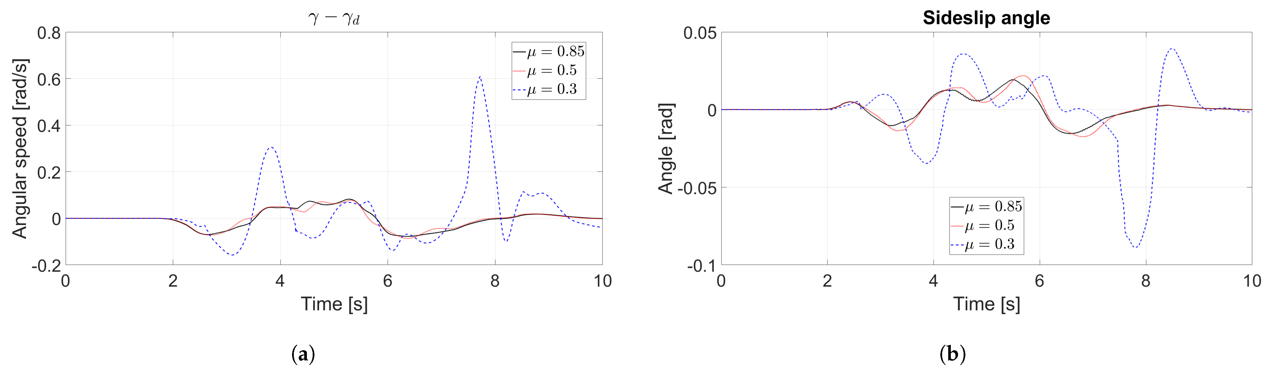
In order to verify the applicability of the proposed controller under more diverse conditions, additional simulations were performed. Figure 8 displays the response of the proposed controller to changes in road friction for the double-lane-change maneuver. When the road’s coefficient of friction was 0.85 or 0.5, the yaw-rate error and sideslip angle responses showed no significant difference. However, when the road’s coefficient of friction was 0.3, the vehicle did not spin out, but the proposed controller had limitations in achieving stable lateral behavior. This implies that AWD and eLSD systems alone cannot reliably control the vehicle in all situations and that additional intervention from electronic control systems such as ESC and an ABS is necessary under extreme driving conditions.
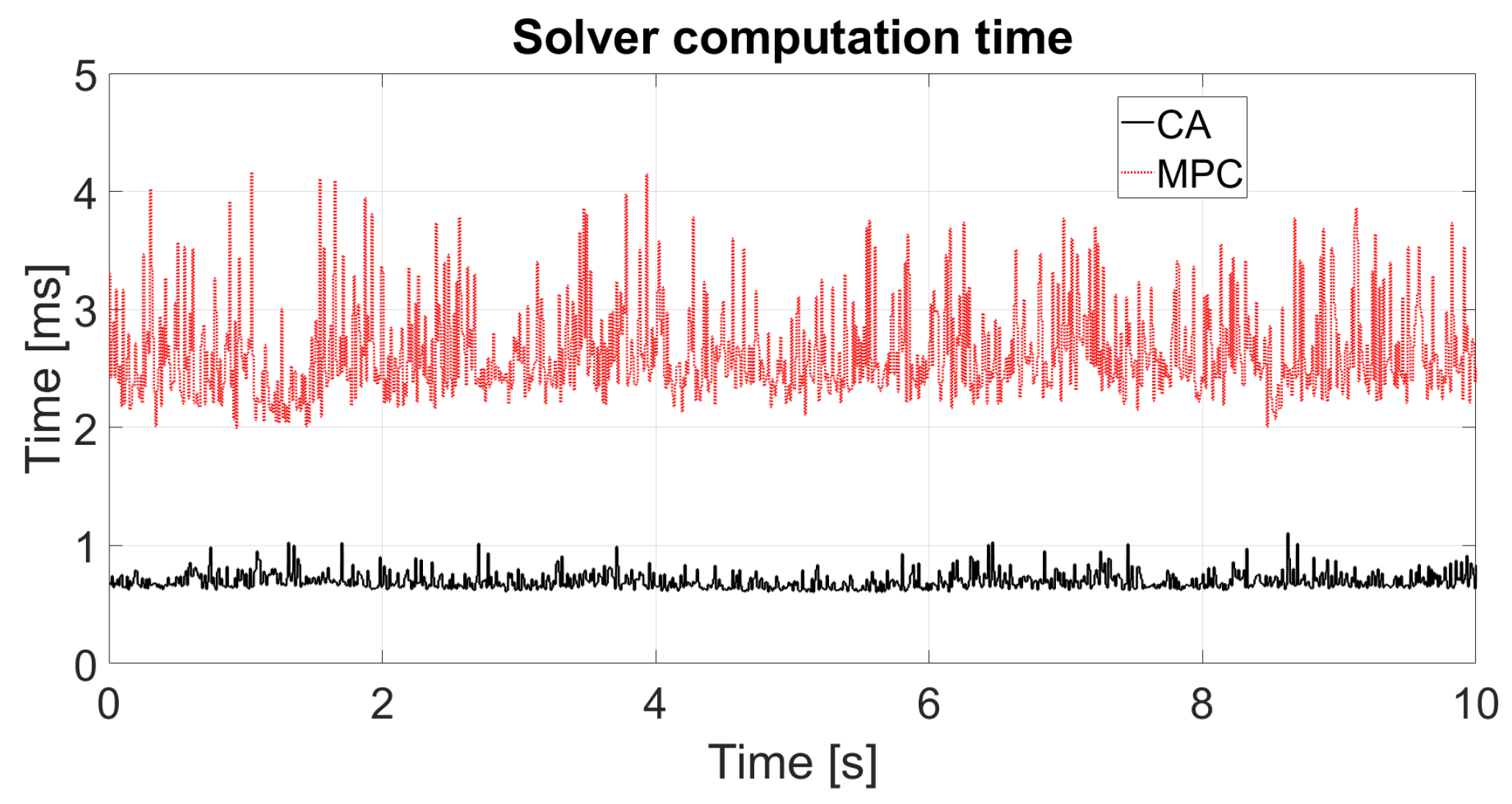
Figure 9 compares the solver computation time of the proposed control allocation method with that of the MPC method introduced in [27]. The computation time was measured at each controller time step using the MATLAB tic and toc functions. The same optimization solver was used for both controllers to ensure a fair comparison. The proposed control allocation method requires less than half of the computation time required by the MPC method. Moreover, the computational advantage of the proposed method is expected to become more significant in real-time implementation because the computation time of the estimator, which is based on a high-dimensional prediction model, was not considered in this comparison. These results indicate that the proposed control allocation method is suitable for real-time AWD and eLSD control applications.

5. Conclusions

This study proposed an integrated control allocation method for a vehicle equipped with AWD and eLSD systems. First, a mathematical vehicle and driveline model was formulated to represent the relationship between the clutch engagement forces and the vehicle’s motion. Based on this model, the input constraints of the transfer clutch and the left/right eLSD clutches were derived by considering the mechanical structure of the driveline and the vehicle operating conditions. Since the AWD–eLSD system has three control inputs for two representative virtual control objectives, the system was formulated as an overactuated system, and a WLS control allocation method was applied. The effectiveness of the proposed controller was evaluated using CarSim–Simulink co-simulations under two acceleration scenarios: acceleration during steady-state cornering and acceleration during a double lane change. In each scenario, high-friction and medium-friction road conditions were considered. The proposed controller was compared with an uncontrolled case and a maximum eLSD clutch input case. The simulation results showed that the proposed controller reduced yaw-rate tracking error while maintaining small sideslip angles and bounded rear-wheel slip ratios. In particular, under the medium-friction double-lane-change condition, the uncontrolled vehicle and the maximum eLSD input case failed to maintain stable lane-following behavior, whereas the proposed controller completed the maneuver by properly coordinating the transfer clutch and the left/right eLSD clutches. The results also showed that applying the maximum eLSD clutch force is not always beneficial. Although eLSD engagement can generate additional yaw moment, excessive clutch input can reduce the lateral tire force margin and increase sideslip or wheel slip, especially under reduced-friction conditions. The proposed control allocation method avoids unnecessary maximum clutch engagement and distributes the available actuator inputs according to the required virtual control demand. Therefore, it improves the balance among yaw-rate tracking, lateral stability, and slip suppression. In addition, the proposed method reduced the solver computation time compared with the MPC-based approach. This result supports the suitability of control allocation for real-time implementation in AWD and eLSD control systems. Despite the suggested method’s effectiveness in improving control performance, this paper also has limitations. In particular, since the proposed controller does not include an estimator design for longitudinal velocity and the road surface’s coefficient of friction, which significantly affect controller performance, definitive verification of the controller’s stability and performance is not guaranteed. To address these weaknesses, future work should involve integrated validation of the estimator and controller using real vehicles or a high-fidelity HiLS environment. Some improvements for WLS methods also exist. Among them, the determination of virtual inputs that clearly decouple vehicle dynamics and tire force utilization, the modification of input constraints to consider tire–road adhesion limits, and the method for optimization of weighting factors in control allocation are major candidates for achieving globally optimal results. Further improvement of the control allocation framework is also expected by considering more detailed eLSD clutch dynamics, including partial lock-up behavior and the transition between slipping and lock-up states.


Funding

This work was supported by the Glocal University 30 Project of the Korea National University of Transportation in 2025.

Institutional Review Board Statement

Not applicable.

Informed Consent Statement

Not applicable.

Data Availability Statement

The original contributions presented in this study are included in the article. Further inquiries can be directed to the corresponding author.

Conflicts of Interest

The author declares no conflicts of interest.

Abbreviations

The following abbreviations are used in this manuscript:
AWDAll-Wheel Drive
RWDRear-Wheel Drive
eLSDElectronic Limited-Slip Differential
CGCenter of Gravity
MPCModel Predictive Control
WLSWeighted Least Squares
ECUElectronic Control Unit
AFSActive Front Steering
ARSActive Rear Steering
DYCDynamic Yaw Control
MASMulti-Agent System
IAEIntegral of Absolute Error
Subscripts
1Front left
2Front right
3Rear left
4Rear right

Appendix A

Table A1. Vehicle specifications.
Vehicle ParametersValue
Distance from CG to front and rear axles, l f and l r 1.471 m, 1.539 m
Track width, 2 t w 1.63 m
Height from ground to CG, h0.54 m
Effective wheel radius, R e 0.328 m
Vehicle mass, m2060 kg
Wheel moment of inertia, I w 0.9 k g   m  2
Vehicle yaw moment of inertia, I z 4200 k g   m  2
Rolling resistance, R r 0.015
Front and rear final reduction gear ratios, i f and i r 43/11, 43/11
Table A2. Parameter values used for controller design.
Control ParametersValue
κ 5 × 10 1
W u diag[1, 10, 10]
W v diag[1, 1]
γ p 0.025rad/s
λ d 0.12
k p 1 × 10 3

References

  1. Panzani, G.; Corno, M.; Tanelli, M.; Zappavigna, A.; Savaresi, S.M.; Fortina, A.; Campo, S. Designing On-Demand Four-Wheel-Drive Vehicles via Active Control of the Central Transfer Case. IEEE Trans. Intell. Transp. Syst. 2010, 11, 931–941. [Google Scholar] [CrossRef]
  2. Kinsey, J. The Advantages of an Electronically Controlled Limited Slip Differential. In SAE 2004 World Congress & Exhibition; SAE Technical Paper; SAE International: Warrendale, PA, USA, 2004. [Google Scholar] [CrossRef]
  3. Woo, S.; Jeon, S.; Joa, E.; Shin, D. Enhanced Vehicle Dynamics and Safety through Tire–Road Friction Estimation for Predictive ELSD Control under Various Conditions of General Racing Tracks. Appl. Sci. 2024, 14, 1903. [Google Scholar] [CrossRef]
  4. Kim, H.; Lee, S.; Hedrick, J.K. Active yaw control for handling performance improvement by using traction force. Int. J. Automot. Technol. 2015, 16, 457–464. [Google Scholar] [CrossRef]
  5. Koh, Y.; Her, H.; Yi, K.; Kim, K. Integrated Speed and Steering Control Driver Model for Vehicle–Driver Closed-Loop Simulation. IEEE Trans. Veh. Technol. 2016, 65, 4401–4411. [Google Scholar] [CrossRef]
  6. Jang, I.G.; You, S.H.; Hwang, S.H.; Cho, W. Lateral Stability Control of a 4-Wheel Independent Drive Electric Vehicle Using the Yaw Moment Contour Line Concept. IEEE Access 2021, 9, 136892–136904. [Google Scholar] [CrossRef]
  7. Her, H.; Joa, E.; Yi, K.; Kim, K. Integrated chassis control for optimized tyre force coordination to enhance the limit handling performance. Proc. Inst. Mech. Eng. Part J. Automob. Eng. 2016, 230, 1011–1026. [Google Scholar] [CrossRef]
  8. Cho, W.; Choi, J.; Kim, C.; Choi, S.; Yi, K. Unified Chassis Control for the Improvement of Agility, Maneuverability, and Lateral Stability. IEEE Trans. Veh. Technol. 2012, 61, 1008–1020. [Google Scholar] [CrossRef]
  9. Zhang, Q.; Wang, H.; Cai, Y.; Xie, W.F.; Sun, X.; Chen, L. Stability-constrained coordinated control strategy for vehicle chassis integrated AFS and DYC via reinforcement learning. Control Eng. Pract. 2026, 175, 107122. [Google Scholar] [CrossRef]
  10. Liang, J.; Shen, C.; Xia, X.; Pi, D.; Yin, G. Robust Game-Theory Control for All-Wheel Steering to Enhance Vehicle Handling Stability Performance. IEEE Trans. Syst. Man Cybern. Syst. 2025, 55, 9230–9241. [Google Scholar] [CrossRef]
  11. Camacho, E.; Alba, C. Model Predictive Control; Advanced Textbooks in Control and Signal Processing; Springer: London, UK, 2013. [Google Scholar]
  12. Borrelli, F.; Bemporad, A.; Morari, M. Predictive Control for Linear and Hybrid Systems; Cambridge University Press: Cambridge, UK, 2017. [Google Scholar]
  13. Borrelli, F.; Bemporad, A.; Fodor, M.; Hrovat, D. An MPC/hybrid system approach to traction control. IEEE Trans. Control Syst. Technol. 2006, 14, 541–552. [Google Scholar] [CrossRef]
  14. Beal, C.E.; Gerdes, J.C. Model Predictive Control for Vehicle Stabilization at the Limits of Handling. IEEE Trans. Control Syst. Technol. 2013, 21, 1258–1269. [Google Scholar] [CrossRef]
  15. Choi, M.; Choi, S.B. Model Predictive Control for Vehicle Yaw Stability with Practical Concerns. IEEE Trans. Veh. Technol. 2014, 63, 3539–3548. [Google Scholar] [CrossRef]
  16. Jeong, Y. Integrated Vehicle Controller for Path Tracking with Rollover Prevention of Autonomous Articulated Electric Vehicle Based on Model Predictive Control. Actuators 2023, 12, 41. [Google Scholar] [CrossRef]
  17. Jalali, M.; Khosravani, S.; Khajepour, A.; ken Chen, S.; Litkouhi, B. Model predictive control of vehicle stability using coordinated active steering and differential brakes. Mechatronics 2017, 48, 30–41. [Google Scholar] [CrossRef]
  18. Jalali, M.; Hashemi, E.; Khajepour, A.; ken Chen, S.; Litkouhi, B. Model predictive control of vehicle roll-over with experimental verification. Control Eng. Pract. 2018, 77, 95–108. [Google Scholar] [CrossRef]
  19. Kim, E.; Kim, J.; Sunwoo, M. Model predictive control strategy for smooth path tracking of autonomous vehicles with steering actuator dynamics. Int. J. Automot. Technol. 2014, 15, 1155–1164. [Google Scholar] [CrossRef]
  20. Johansen, T.A.; Fossen, T.I. Control allocation—A survey. Automatica 2013, 49, 1087–1103. [Google Scholar] [CrossRef]
  21. Oppenheimer, M.W.; Doman, D.B.; Bolender, M.A. Control Allocation for Over-actuated Systems. In Proceedings of the 2006 14th Mediterranean Conference on Control and Automation, Ancona, Italy, 28–30 June 2006; pp. 1–6. [Google Scholar] [CrossRef]
  22. Härkegård, O. Dynamic Control Allocation Using Constrained Quadratic Programming. J. Guid. Control. Dyn. 2004, 27, 1028–1034. [Google Scholar] [CrossRef]
  23. Plumlee, J.; Bevly, D.; Hodel, A. Control of a ground vehicle using quadratic programming based control allocation techniques. In Proceedings of the 2004 American Control Conference, Boston, MA, USA, 30 June–2 July 2004; Volume 5, pp. 4704–4709. [Google Scholar] [CrossRef]
  24. Kim, S.; Oh, J.; Choi, S. Gear shift control of a dual-clutch transmission using optimal control allocation. Mech. Mach. Theory 2017, 113, 109–125. [Google Scholar] [CrossRef]
  25. Rajamani, R. Vehicle Dynamics and Control, 2nd ed.; Springer: New York, NY, USA, 2012. [Google Scholar]
  26. Lampaert, V.; Al-Bender, F.; Swevers, J. A generalized Maxwell-slip friction model appropriate for control purposes. In Proceedings of the 2003 IEEE International Workshop on Workload Characterization (IEEE Cat. No.03EX775), St. Petersburg, Russia, 20–22 August 2003; Volume 4, pp. 1170–1177. [Google Scholar] [CrossRef]
  27. Jung, H.; Pyun, B.; Choi, S. Model Predictive Control of an All-Wheel Drive Vehicle Considering Input and State Constraints. Int. J. Automot. Technol. 2020, 21, 493–502. [Google Scholar] [CrossRef]
  28. Jung, H.; Jung, D.; Choi, S.B. LQR Control of an All-Wheel Drive Vehicle Considering Variable Input Constraint. IEEE Trans. Control Syst. Technol. 2022, 30, 85–96. [Google Scholar] [CrossRef]
  29. Jung, H.; Choi, S. Modified Generalised Maxwell Slip Based Electro-Hydraulic Transfer Case Modeling for All-wheel Drive Vehicle Simulation. Int. J. Automot. Technol. 2023, 24, 45–54. [Google Scholar] [CrossRef]
  30. Lv, J.; He, H.; Liu, W.; Chen, Y.; Sun, F. Vehicle Velocity Estimation Fusion with Kinematic Integral and Empirical Correction on Multi-Timescales. Energies 2019, 12, 1242. [Google Scholar] [CrossRef]
  31. Han, K.; Lee, E.; Choi, M.; Choi, S.B. Adaptive Scheme for the Real-Time Estimation of Tire-Road Friction Coefficient and Vehicle Velocity. IEEE/ASME Trans. Mechatron. 2017, 22, 1508–1518. [Google Scholar] [CrossRef]
  32. Jung, H.; Choi, S.B. Real-Time Individual Tire Force Estimation for an All-Wheel Drive Vehicle. IEEE Trans. Veh. Technol. 2018, 67, 2934–2944. [Google Scholar] [CrossRef]
Figure 1. Vehicle planar full car model.
Machines 14 00919 g001
Figure 2. Mechanical structure of transfer case and eLSD system.
Machines 14 00919 g002
Figure 3. Diagram of the observer-based AWD and eLSD controller.
Machines 14 00919 g003
Figure 4. Rapid acceleration during steady-state cornering on a road with a high coefficient of friction ( μ = 0.85 ) (a) Yaw-rate error. (b) Sideslip angle. (c) Rear-wheel slip ratio. (d) Drive-axle torque.
Machines 14 00919 g004
Figure 5. Rapid acceleration during steady-state cornering on a road with a medium coefficient of friction ( μ = 0.5 ) (a) Yaw-rate error. (b) Sideslip angle. (c) Rear-wheel slip ratio. (d) Drive-axle torque.
Machines 14 00919 g005
Figure 6. Rapid acceleration during a double lane change on a road with a high coefficient of friction ( μ = 0.85 ) (a) Yaw-rate error. (b) Sideslip angle. (c) Rear-wheel slip ratio. (d) Drive-axle torque.
Machines 14 00919 g006
Figure 7. Rapid acceleration during a double lane change on a road with a medium coefficient of friction ( μ = 0.5 ) (a) Yaw-rate error. (b) Sideslip angle. (c) Rear-wheel slip ratio. (d) Drive-axle torque. (e) eLSD input command.
Machines 14 00919 g007
Figure 8. Response of the proposed controller during a double lane change depending on the variation in road friction (a) Yaw-rate error. (b) Sideslip angle.
Machines 14 00919 g008
Figure 9. Solver computation time for each time step.
Machines 14 00919 g009
Table 1. IAE and peak values of yaw-rate error.
IAE [Rad]Peak (Absolute Value) [Rad/s]
Steady-state cornering
( μ = 0.85 )
No ctrl.0.41670.0875
u 1 r + max eLSD0.19100.1194
Proposed CA0.35370.0813  1
Steady-state cornering
( μ = 0.5 )
No ctrl.0.97450.4860
u 1 r + max eLSD0.51670.1864
Proposed CA0.33790.0802
Double lane change
( μ = 0.85 )
No ctrl.0.33320.0962
u 1 r + max eLSD0.24750.1230
Proposed CA0.29090.0796
Double lane change
( μ = 0.5 )
No ctrl.FailFail
u 1 r + max eLSDFailFail
Proposed CA0.26540.0868
1 The numbers in bold indicate results where performance has improved using the proposed method.
Disclaimer/Publisher’s Note: The statements, opinions and data contained in all publications are solely those of the individual author(s) and contributor(s) and not of MDPI and/or the editor(s). MDPI and/or the editor(s) disclaim responsibility for any injury to people or property resulting from any ideas, methods, instructions or products referred to in the content.